Abstract
In this work, a sliding-mode-based attitude controller constrained with the angular rate for unmanned aerial vehicles (UAVs) is addressed to withstand conditions below the allowable maximum angular velocity of UAVs in order to avoid the possibility of structural failure and to operate UAVs safely. The sliding mode controller suggested in this work defines a new sliding surface, inherently having two equilibrium points. These equilibrium points are carefully inspected, and the stability of the system controlled by means of the proposed approach is also analyzed using Lyapunov stability theory. To highlight the angular-rate constrained attitude control technique, a three-dimensional path is constructed using the Dubins path technique, and three-axis attitude commands for UAV are also generated by augmenting the line-of-sight algorithm. Compared with conventional sliding mode control measures, the excellent performance of the suggested control algorithm has been demonstrated by conducting numerical simulations.
1. Introduction
Various attitude control techniques designed to improve the maneuvering capability of emerging high agile unmanned aerial vehicles (UAVs) have been studied in the past several decades [1]. To meet the requirement for accomplishing complex missions that needed to be performed in a short time, modern UAVs demand increasingly high levels of maneuverability [2]. On the other hands, it is also known that the excessive maneuvering capability of UAVs increases the risk of structural damage or cracks due to induced gravitational forces and moments. Thus, resolving these opposite characteristics properly is very important in order to operate UAVs effectively and safely, which was the major motivation for this study.
Let us review the attitude control techniques applied to UAVs. The most commonly used control technique is the classical proportional-integral-derivative (PID) algorithm, which provides very reliable control performance and stability, despite its simple structure [3]. Nevertheless, due to its inherent limitations as a linear control method, this control law is not appropriate to apply to highly nonlinear systems, and it is quite vulnerable in its control of the system to external disturbances or internal uncertainty [4]. As an alternative, various nonlinear control theories, such as sliding mode control (SMC) [5], backstepping control [6], nonlinear model predictive control [7], and adaptive control [8], have been studied in order to improve the maneuverability of UAVs.
One of the options to increase the maneuverability of modern UAVs is the backstepping algorithm, which is a nonlinear technique that adjusts other state variables by sequentially setting each state as a virtual control input. The drawback of this approach is that it largely relies on having a quite accurate system model. To solve this uncertainty problem in the nonlinear platform, the adaptive backstepping control was augmented by approximating the uncertainty in the system model using a fuzzy-based approach [9]. Meanwhile, to control unsteady and highly nonlinear UAVs, the nonlinear model predictive control technique was introduced [10]. In this approach, the control input is obtained by selecting the current output among the several discretized control outputs, evaluated from the present time to a few seconds by means of the optimization technique. The advantage of this method is that it allows us to evaluate the optimal control input for a given cost function by taking into account the various constraints. However, this powerful merit ironically leads to a disadvantage in that it requires very high computational resources to evaluate the optimal value. That is, the larger the size of the constraint to be considered in the optimization process, the greater the computation burden required [11]. In an effort to reduce the amount of computational resources, some studies have been conducted. As an effective method of support for model predictive control, the neural network technique was introduced [12]. Note that this adaptive-like control involves a technique in which the gain value of the controller changes according to the state of the system, and has a disadvantage in that the control performance depends on the initial value of the gain. Therefore, learning-based control algorithms including the adaptive control technique have an implicit burden—the question of how to select the stable initial values or parameters when this technique is chosen as the primary option to control the actual platform.
The sliding mode control (SMC) approach for UAV attitude control applications has useful characteristics, including a guaranteed control response time. This approach is a control method that creates a sliding surface with state variables to control a nonlinear system and directs the state variables to the control target by sliding on the surface using a reaching law, which guarantees robustness [13]. This strong property leads to the biggest advantage of SMC. On the other hand, it is also known that there is the drawback of a high-frequency oscillation phenomenon, that is, a chattering problem, in the process of controlling and compensating for disturbance and uncertainty. To solve this problem, several studies have been carried out to find an effective reaching law [14,15].
In spite of the efforts to improve the attitude control capability of UAVs in the presence of external disturbances and internal uncertainty, less attention has been paid to structural constraints or dynamic limitations for safe operations in controller design. Merely increasing the maneuvering capability of UAVs does not cover the safe operation of UAVs to conduct complex missions. In this work, a nonlinear control law for driving below the allowable maximum angular velocity is considered in order to realizethe possibility of structural failures and safety uncertainties. To ensure the stable dynamic ranges and the capability of attitude control, the sliding mode control (SMC) technique is taken in account. Since this not only requires fewer computational resources, but also has strong properties against model uncertainty and perturbation, SMC could be one of the reliable options used in the implementation of actual UAVs. The newly designed control law in this work is called constrained SMC (CSMC). To guarantee the stable dynamic range by limiting the angular rate, a sliding surface is proposed. It is revealed that the suggested sliding surface has two equilibrium points in order to meet the exceptional requirement examined in this work. Thus, these equilibrium points are carefully observed, and the stability at each point is also investigated. Finally, the attitude control law, using the CSMC approach, is applied to UAVs and the stability is proven using Lyapunov stability theory. Next, a 3-dimensional guidance algorithm for path following of UAVs is additionally addressed to highlight the control law. To provide guidelines for the operation of UAVs under the maximum allowable angular rate, the concept of Dubins curves has been considered in order to generate 3-dimensional smooth guidance curves. Then, the path-following algorithm is augmented to CSMC, as proposed in this paper. The excellent performance of the proposed approach, in cooperation with the path-following technique, for safe UAV operations is demonstrated by integrated simulation studies involving external disturbances and internal uncertainties.
This paper is organized as follows. First, the equations of motion of a fixed-wing UAV are introduced in Section 2. Then, the conventional SMC is briefly reviewed, and the SMC-based attitude control method limiting the angular rate of UAVs is addressed in Section 3. The uniquely designed sliding surface is also described. Next, the stability analysis of the closed-loop system with the proposed control law is given for two equilibrium points. Then, the 3-dimensional path generation algorithm for UAV attitude command generation is followed in Section 4 using the Dubins curve concept. Finally, the proposed control scheme is demonstrated using numerical simulation studies. In this simulation, the CSMC technique is compared with the conventional SMC. Furthermore, to highlight the proposed control method, several harsh scenarios are provided to ensure that the UAV with the generated attitude command follows a given guidance route smoothly and safely.
2. Mathematical Model of UAVs
Various types of UAVs, for example, fixed-wing, rotary-wing, and multi-copter, have been designed and studied during the past several decades. Note that a fixed-wing UAV is employed in this paper to design the control law. Now, let us start by reviewing the coordinate system presented in Figure 1. The position vector of the illustrated UAV is defined by , and the attitude is defined by the Euler angle , which can also be converted to quaternion parameters by the attitude transformation. Note that most of the literature for the attitude representation of fixed wing UAVs has been focused on Euler angles rather than quaternions, since the Euler angle is much more intuitive for controller design. The attitude control law considered in this work, however, employs the quaternion representation due to its simple mathematical structure. Thus, the governing equations of motion of the fixed-wing UAV are given by [16].
where represents the linear velocity vector, and is the angular velocity vector of the UAV in the body frame. and denote the aerodynamic force and moment in the body frame, respectively. , and T represent the mass of the UAV, the gravitational constant, and the thrust of the UAV, respectively. Furthermore, represents the identity matrix. The inertia matrix J is the symmetric positive matrix and is written in the body frame as
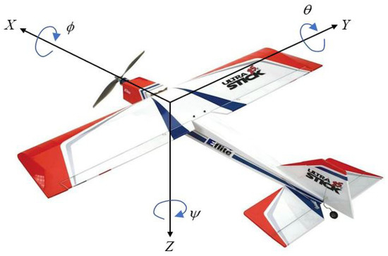
Figure 1.
The coordinate system of a UAV.
The attitude transformation matrix from the body frame to the inertia frame can be expressed by the quaternion as
Note the operator on any vector represents a skew-symmetric matrix defined as
The aerodynamic force and moment F and M are written as [16]
where the aerodynamic coefficients can be given by
Furthermore, b, S and denote the wingspan, the wing area, and the mean aerodynamic chord (MAC) of the UAV, respectively. Furthermore, represents dynamic pressure, e is the Oswald efficiency number, and is the wing aspect ratio. Lastly, , and are the control input for the aileron, elevator, and rudder, respectively. The angle of attack and the sideslip angle are defined respectively as
Note that is the airspeed of the UAV.
To facilitate the derivation of an attitude controller design, the aerodynamic moment in Equation (10) can be linearly decoupled with two parts. Thus, the aerodynamic moment can be rewritten in a simple vector form with Equations (16)–(18) as
where
3. Angular-Rate-Constrained Nonlinear Attitude Control
In this section, a new nonlinear attitude control law considering the maximum angular rate for fixed-wing UAVs is presented. To employ this unique approach, the sliding mode control (SMC) technology concept is utilized.
3.1. Sliding Mode Control
Let us first consider the baseline SMC. The first step in this technique is to reach the designed sliding surface. Then, the second step is the sliding stage, in which the sliding variable reaching the sliding surface goes to zero, which means that state errors converge to zero. For attitude control using the sliding control approach, the representative sliding surface is chosen as
and a simple reaching law is written as
where is the vector part of quaternion error defined as and is the quaternion command, and the operator ⊗ refers to the quaternion multiplication. Furthermore, a and k are positive design parameters. Note that is the signum function, defined as
To compute the control output from the sliding surface, the time derivative of sliding surface in Equation (25) is expressed as
Inserting the angular acceleration, , in Equation (5) into the above equation leads to
In terms of from the above equation, the control input is expressed as
It is known that the discontinuity in the reaching law introduces the chattering problem. To release the burden of chattering, the alternative reaching law is given by
where is a design parameter ranging from 0 to 1, and is a matrix function defined as
and is the diagonal matrix in this case. By inserting the above reaching law into Equation (30) to mitigate the chattering problem, the control input is rewritten as
Note that the final form of the control input is the attitude sliding mode control law for UAVs, overcoming the inherently introduced chattering problem.
Lemma 1.
Once the sliding manifold is satisfied with properly chosen parameters, then the desired attitude maneuver can be achieved, i.e., the variable and will converge to zero. That is,
Proof.
Assume that the sliding surface in Equation (25) is zero, and , then it can be expressed as
Substituting into Equation (4) and setting introduces
Due to the norm constraint of the quaternion given by , the right-hand side of the equation is rewritten as
The closed-form solution of the differential equation for a given time is . As a sufficient time has elapsed, it can be seen that converges to 1:
With converging to one, this means that converges to the zero vector due to the norm constraint of the quaternion after a sufficient time has elapsed. Consequently, the sliding surface approaches zero, which means that converges to zero independently. Furthermore, also converges to zero according to Equation (36). Thus, Lemma 1 is proven. □
3.2. Angular-Rate-Constrained Sliding Mode Control
In this subsection, a modified control law based on SMC is introduced by defining a sliding surface proposed in this work. Let us first assume that the fixed-wing UAV has limited maneuverability to prevent structural failure or cracks or to operate various missions safely. Without the loss of generality, the angular rate is directly linked with the magnitude of the centrifugal force according to the given airspeed of the UAV. Thus, it is natural that the maneuverability constraint can be converted to the angular rate limitation of the UAV. That is,
where is the angular rate of UAV for each body axis, and is the allowable maximum angular speed of UAV to meet the maneuverability constraints. Now, to satisfy the angular rate constraint, the new sliding surface suggested in this work is written as
where the saturation vector function is defined as
and the saturation scalar function can be given by
Furthermore, L is the limiting parameter, obtained by dividing the maximum angular rate by the design parameter a. The function compares two components and selects a smaller value so that the saturation function selects a smaller value via the comparison between the component of the quaternion absolute error and the limiter L. From the inherent representation of the new sliding surface, there are two equilibrium points, setting . That is, and . The first equilibrium point is related to the attitude control purpose, and the second equilibrium point is deeply related to the angular rate limitation by forcing the UAV not to exceed the given limitation. Let us consider for the second equilibrium point that the quaternion absolute error is larger than the limiter L. Then, will be L according to Equation (43). Since , the saturation function can be the allowable maximum angular rate, that is, . Thus, the second equilibrium point is related with the allowable maximum angular rate such that .
For the angular rate constrained control law design, the time derivative of the sliding surface in Equation (41) is given by
where D is the diagonal matrix with the element defined as
Note that is differentiation of the scalar function, and it becomes 0 or 1 according to the algebraic comparison of L and . Thus, by substituting Equations (5) and (31) into (45), the constrained sliding mode control (CSMC) input can be expressed as
It is noted that the control input induced from the suggested sliding surface is the angular-rate constrained attitude control law for fixed-wing UAVs based on the sliding mode control. As seen in Equation (48), the control law is dedicated to the magnitude of attitude errors. If the attitude error for each axis is larger than the reference value of L, the term of is eliminated to improve the maneuverability. Otherwise, the term is activated, and the control law in Equation (48) supports both and to approach zero. In other words, it can be interpreted that the control law plays two important roles, since there are two equilibrium points. The first equilibrium point of the sliding surface, , is related to the case of . In this case, the control law allows us to reach the allowable maximum angular speed of the UAV in order to improve the maneuverability. This strategy is made possible by approaching the first equilibrium point. Next, for the second equilibrium point, , connected with the case of , the control input causes the attitude error and angular velocity to converge to zero by controlling the sliding surface to reach the second equilibrium point. This property can be regarded as the unique characteristic of the constrained sliding mode control approach suggested in this paper.
3.3. Stability Analysis
Before verifying the stability of the control law, let us first inspect the overall process of the control law to ensure that the sliding surface works appropriately to achieve the control objective. As mentioned previously, there are two equilibrium points in the sliding surface. This means that the structure of the proposed control law can vary depending on the amount of attitude errors and the allowable maximum angular rate.
Suppose that a large attitude command is generated for the UAV in a steady state so that a large amount of attitude errors are applied to CSMC. It is matched with the case of . That is, the first step to achieve the goal is to adjust the angular rate to converge to the allowable maximum angular rate . This can done by sliding at the first equilibrium point. It is noted that approaching the first equilibrium point is deeply related with the maneuverability, since the angular rate increases quickly to the allowable maximum angular rate of the UAV. Consequently, due to the consistent angular rate applied to the UAV at the first equilibrium point, the magnitude of the attitude errors gradually decreases below the given reference L. This is the reason the control law can naturally move on to the second step, . As seen previously, the second step is to approach the second equilibrium point, which is a step for controlling both the quaternion error and the angular rate , causing them to converge to zero.
Let us carefully investigate the sliding surface in detail. According to the attitude error, the sliding surface defined in Equation (41) can be divided by two forms given by
Equation (49) is the sliding surface in the case of large attitude errors enough to be larger than L, so that the point satisfying is the equilibrium point. Furthermore, it is obvious that the variable of in Equation (47) becomes 0. Let us substitute the control law in Equation (48) into the governing equations of motion of UAVs in Equation (5). Then, it is found that the relationship between and s is given by
From the above equation, it can be seen that the angular acceleration is opposite to the sign of the sliding surface in Equation (49).
Assuming that the UAV is initially in a steady state, the angular rate of the UAV is zero. It holds from Equation (49) so that the sign of is identical with the quaternion error, . This property is still valid, whereas is approaching to zero. In other words, It is valid before the angular rate of UAV, , is identical with the allowable maximum angular speed, . From Equation (51), it is obvious due to the fact that the signs of the quaternion error and the angular acceleration are opposite. That is, the angular rate increases while the quaternion error decreases. Consequently, becomes so that the sliding surface goes to zero, . Then the angular acceleration in Equation (51) becomes zero. Finally, it is noted that the angular rate reaching the allowable maximum angular rate remains unchanged, whereas the quaternion error decreases continuously to be smaller than L. Once the quaternion error becomes small after a sufficient time has elapsed, then the variable is switched to one. This is when the sliding surface of Equation (49) turns into Equation (50). It can be also seen that the sliding surface is the same as that of the conventional SMC in Equation (25). Therefore, the point where and become zero is the equilibrium point.
Now, let us investigate the stability of the closed-loop attitude control system utilizing CSMC to ensure that the motion of the sliding surfaces work correctly. Stability analysis is required for each sliding surface. For the stability of the closed-loop system, the representative Lyapunov candidate by the first sliding surface in Equation (49), is defined as
Inserting Equation (45) into the time derivative of the Lyapunov candidate leads to
Then, let us substitute Equation (5) into the above equation, and replace the control input with Equation (48). Then, the time derivative of the Lyapunov candidate is rewritten as
Note that D is zero in this case.
Moreover, the second term of the right-hand side of the above equation is always positive. That is,
Thus, the time derivative of the Lyapunov candidate is given by
where denotes the two-norm of . Since the time derivative of the Lyapunov candidate is always negative, the closed-loop system is asymptotically stable. This means that for a given initial condition of and , the sliding surface, , in Equation (49) will converge to the first equilibrium point, .
Once again, for the closed-loop system stability by the second equilibrium point, the identical Lyapunov candidate by the sliding surface in Equation (50) is also defined as
By proceeding identically with the previous case, the time derivative of the Lyapunov candidate is also written as
Note that the variable D does not disappear in this case. However, applying the control input in Equation (48), the remaining procedure is identical with that of the previous case. Since the closed-loop system is asymptotically stable for the given condition of , the sliding surface, , in Equation (50) will converge to the second equilibrium point, that is, , which is proven by Lemma 1.
3.4. Summary
For the attitude control of fixed-wing UAVs that are able to be operated within limited angular rates, the sliding mode control investigated in this section, similar to variable structure control technologies, is summarized as follows. This technique consists of two control laws separated by the amount of the attitude errors induced by the attitude commands and the allowable maximum angular rate of the UAV. If the attitude errors are larger than the limiter, for example, , then the related sliding surface and control law are given respectively by
otherwise, the relevant sliding surface and the control law are expressed respectively as
4. 3D Path-Following Technique
In this section, a three-dimensional guidance algorithm for the path following of waypoints is additionally employed to ensure that the control law in Equation (48) works effectively. To provide the guidelines of the angular rate for a given UAV to be operated safely within the allowable forces and moment, the concept of the Dubins curve is introduced for the generation of three-dimensional smooth guidance curves. Thus, let us describe in this section the entire process used to generate the 3-dimensional Dubins path and the tracking algorithm with the turning radius of the UAV, determined for safe operations.
4.1. Dubins Path Generation
It is known that the Dubins path consists of only a few circles and lines so that it can be mathematically simplified for the generation of waypoint guidance for UAVs. The illustrative Dubins path indicating these two points is illustrated in Figure 2. The process of geometrically generating the Dubins path, for example, a CSC (Circular, Straight, Circular line) type in the 3D space is reviewed briefly in [17]. The minimum turning radius of the UAV, , can be first determined by the maximum allowable angular rate, , and the given airspeed, . Assume that there is a UAV at a position heading to the unit vector, . There is an another waypoint heading to the unit vector that the UAV must pass. In Figure 2 the straight line, , connecting two points of and is the Dubins line to generate the guidance route. The unit heading vector at a position , which can be evaluated by means of the velocity vector of the UAV, is given by
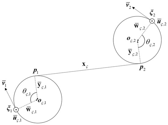
Figure 2.
Geometry of the Dubins path connecting two waypoints of and .
To define the three orthogonal unit vectors at the point, the vector perpendicular to the plane, consisting of the Dubins line and velocity vector, can be given by
and the orthogonal unit vector is also written as
Then, the third orthogonal unit vector, namely, the radius unit vector which is oriented toward the center of the circle from the position is evaluated as
Then, using the unit vector and a given way point vector, the center point of the circle can be computed as
Next, the unit radius vector, , leading from the point to the center of the circle is given by
where is the unit vector given by . The point at which the tangent meets in the circle is also computed with respect to the center of the circle as
Consequently, since there are two waypoints illustrated in Figure 2, the straight line connecting two points and can be evaluated as
Furthermore, the angles denoted and shown in Figure 2 are computed using the inner product of the two unit vectors as, respectively,
From the geometrical relationships, the straight line vector is also given by
Now, for the given waypoints, the straight line can be obtained by resolving Equation (73) so that the guidance path from point to point can be designed. However, Equation (73) is the nonlinear multivariate system so that it is unable to obtain the closed-form solution. It is favorable to employ a numerical solver.
4.2. Path Tracking
In this subsection, a nonlinear UAV path tracking algorithm similar to the line-of-sight guidance algorithm is addressed to follow the Dubins path explained previously for the waypoint guidance. The kinematic equations of motion for UAVs with respect to time are simply given by [18]
where the airspeed is assumed to be constant, and is the flight path angle of the UAV.
Now, let us assume that there is a Dubins path, , to be tracked. With respect to the distance variable, , the kinematic equations of the Dubins path can be also expressed as
where and are the reference angles for the UAV to be tracked, and and are the reference locations to follow the Dubins path.
Also, let us define a straight line tangent to the path at a given point . A reference point on the line can be defined as
where indicates the location that is closest to the UAV, and is the positive parameter.
When the positive parameter is chosen close to zero, the reference point on the line will be located very far from the point . Meanwhile, when is selected as almost , then the reference point is identical with the point . In this work, the reference point is the actual point to be employed for the path tracking algorithm by adjusting .
If the UAV is located far from the guidance route, approaching the closest Dubins path could be the first priority for tracking the path. To accomplish this option, the parameter needs to be chosen as a large positive value so that the reference point can be identical with the point closest to the UAV. On the other hand, if the UAV is located close to the guidance route, heading toward the tangent direction of the Dubins path could be the priority to track the path appropriately. For this scenario, it can be achieved by selecting close to zero. Thus, adjusting with respect to the errors between the UAV position and the point is very important to track the given route.
Therefore, the attitude command angles of are chosen with respect to the distance error between the reference point, and and the UAV’s actual location. Thus, the relevant relationships are given geometrically as
where, .
As is known, most fixed-wing UAVs allow roll commands to follow the heading commands. Thus, the path in the lateral dimension for fixed-wing UAVs is usually controlled by a coordinated turn maneuver by controlling the ailerons to achieve the desired roll command . When the UAV is banked at an angle , the lift by the wings can be divided into two components. For the successive coordinated turn maneuver, the requirement is given by
where is the lateral acceleration command. Furthermore, manipulating the two requirements leads simply to
In order to obtain the roll command from the yaw command, let us assume a reference point on the desired trajectory shown in Figure 3. The distance between the reference point and the UAV is denoted as l, and the angle between the velocity vector and the line l is the yaw error defined as . Then, the lateral acceleration command is given by [19]
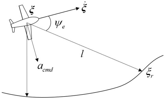
Figure 3.
Nonlinear lateral control for the UAV.
By inserting the acceleration command into Equation (87), the roll command is expressed as
Note that the pitch command is also evaluated by . From the evaluated three-axis attitude command represented by Euler angles , , the quaternion command, , is generated to employ the suggested control law to follow the given guidance route.
5. Numerical Simulations, Results, and Discussions
In this section, the proposed attitude control law and the path-following algorithm are examined using numerical simulations. Let us first explain the simulation conditions. The US 25e model [16,20] is employed for the numerical model of the fixed wing UAV in this work. The specifications of the model are listed in Table 1. The aerodynamic coefficients in Equations (11)–(18) for a given airspeed m/s are also listed in Table 2.

Table 1.
Characteristics for US 34e.

Table 2.
Parameters of aerodynamic coefficients for US 25e.
The proposed constrained sliding mode control (CSMC) approach is compared with the conventional SMC in this simulation. The gains for each control law are listed in Table 3 and Table 4, respectively. Note that by employing the angular rate constraint, deg/s chosen for this simulation scenario, there is a slight modification of design parameters between the two control laws. Furthermore, to highlight the excellent performance of the proposed CSMC, wind dust is added to the simulation environment for the time from s to s. To simulate the disturbance varying sinusoidally, the external moment ranging from −0.2 Nm to 0.2 Nm shown in Figure 4 is applied to the UAV.

Table 3.
Design parameters for SMC.

Table 4.
Design parameters for CSMC.
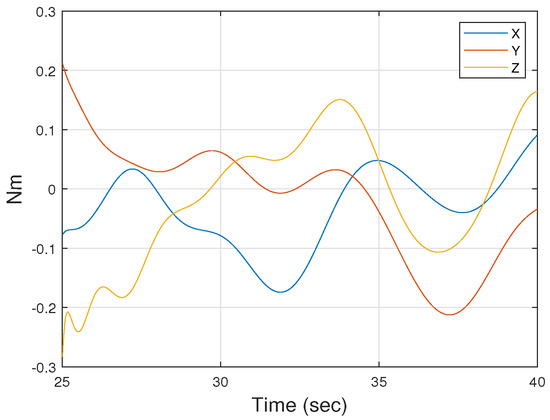
Figure 4.
Scenario of external disturbances applied to the UAV.
Now, let us select some reference waypoints to design the flight path for the UAV. To examine properly the control capability for CSMC, the randomly chosen waypoints and heading unit vectors are listed in Table 5. Then, the Dubins path generation algorithm is applied to the waypoints to design the guidance trajectory. Since the airspeed () and the angular rate limit () of the UAV are chosen as 20 m/s and 10 deg/s, respectively, the turning radius for the Dubins circle can be also evaluated as for this scenario. By applying these parameters and the given waypoints above, the guidance trajectory route from point 1 to point 5 can be calculated simply using Equation (73). The 3-D trajectory generated using only Dubins circles and lines results in Figure 5.

Table 5.
The selected waypoints and heading unit vectors.
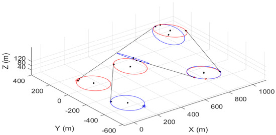
Figure 5.
A 3-dimensional Dubins path constructed by circles and lines for the five waypoints.
In order to verify the tracking capability of the proposed control law, the initial position of the UAV is chosen to be relatively far from waypoint 1. The resultant tracking trajectories by CSMC and SMC laws are indicated in Figure 6. It can be seen that both control laws are able to trace the reference trajectory without difficulty, even though the UAV is initially located far away from waypoint 1. The slight difference between the two tracking paths controlled by the two techniques is evident at the very beginning. This difference originates from the angular rate limitation. The detailed reasons for this are given below in the inspection of the steady state variables. Furthermore, it can be seen that the tracking path is slightly deviated on the first straight path, which shows that the UAV is pushed back due to wind gusts. Except for the first straight path, it can be noted that the UAVs controlled by means of SMC and CSMC follow the curved path and other straight paths without significant differences.
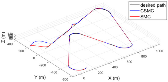
Figure 6.
Tracking lines of the UAVs controlled by means of SMC and CSMC, respectively.
The detailed plots of the steady state variables for the given scenario are displayed in Figure 7, Figure 8 and Figure 9. Extracted from the attitude commands by Equations (83), (84) and (89) to track the designed route, the relevant UAV attitude commands are plotted in Figure 7. The attitude tracking histories using the control laws are also displayed in the Figure as well. Let us focus on the very beginning of the plots. It is obvious that in the case of SMC the attitude command in Figure 7a is quickly followed without errors, whereas in the case of CSMC the attitude tracking time illustrated in Figure 7b is slower than that of SMC due to the limitation of the angular rate. Then, let us inspect the angular rate of the UAV. Figure 8 is the graph of the angular rate. As expected, unrealistic large angular rates take place in Figure 8a to compensate for the generated large attitude errors in the beginning for the UAV controlled by means of SMC. Meanwhile, the angular rate of the UAV controlled by means of CSMC over the simulation time is bounded by the given maximum angular rate, which is plotted in Figure 8b. It is believed that several control transitions have occurred to ensure that the angular velocity does not exceed the angular velocity limit.
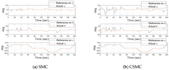
Figure 7.
Time histories of Euler angles.
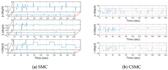
Figure 8.
Angular rate responses of the UAV.
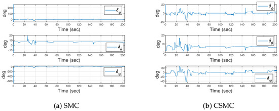
Figure 9.
The deflection angles of control surfaces generated by the control laws.
Lastly, by examining the control input histories applied to the UAV, it can be highlighted that the proposed CSMC has clear advantages for actual applications. When SMC is utilized, very unrealistic control inputs are applied to the UAV to compensate for the attitude errors introduced by the relatively large attitude command at the beginning of the scenario, which is plotted in Figure 9a. The CSMC approach proposed in this work does not generate the excessive deflection of the control inputs shown in Figure 9b. This characteristic originates from the control law restricting the angular rate, even though very large attitude commands are applied. Therefore, it is believed that the proposed technique providing the permissible control input can be applicable to actual applications.
Of course, the maneuverability of UAVs can deteriorate, when the proposed CSMC is chosen to be utilized primarily for the attitude control of UAVs. However, depending upon whether the emphasis is placed on significant emergencies for structural damage, cracks or safe operation as the first priority to accomplish complex missions, there are several options available for control.A numerical simulation according to the angular velocity limit is performed using CSMC using an identical scenario to that which has been conducted previously. Without the loss of generality, only the tracking histories are examined in this simulation study. Consequently, it can be noted in Figure 10 that when the proposed CSMC is applied, it is evident that the attitude maneuverability can even be identical to that of SMC. Therefore, the control law proposed can be applicable to actual applications by adjusting the angular rate limit, properly satisfying the attitude control capability requirements.
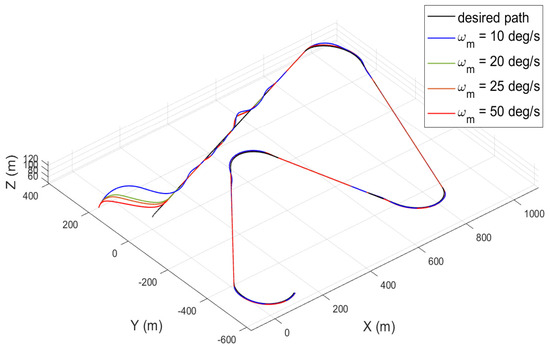
Figure 10.
Tracking histories conducted by CSMC according to the angular rate limit variations.
6. Conclusions
A sliding mode-based attitude controller was proposed in the consideration of angular rate constraints for UAVs in this work. The sliding surfaces suggested have two different equilibrium points. These equilibrium points were evaluated through stability analysis.One of these points is used for maneuverability improvements within the allowable maximum angular rate for the safe operation of UAVs; the other is used to determine the attitude control capability. Switching between the two equilibrium points defined by the sliding surfaces is conducted very smoothly according to the magnitude of the attitude errors. Numerical simulations were performed on the path generated by means of the Dubins algorithm in the presence of external disturbances. It was demonstrated clearly that the guidance path generated was followed by the UAVs using the proposed technique, while satisfying the angular rate constraints. Consequently, it is also believed that the proposed technique is appropriate for actual applications to accomplish complex missions safely by operating the UAV within the allowable structural force and moment conditions.
Author Contributions
Conceptualization, H.L.; methodology, H.L.; software, S.-h.J.; validation, S.-h.J., Y.Y. and H.L; formal analysis, S.-h.J., Y.Y. and H.L.; investigation, Y.Y.; resources, H.L.; data curation, S.-h.J. and H.L.; writing—original draft preparation, S.-h.J. and Y.Y.; writing—review and editing, H.L.; visualization, S.-h.J. and Y.Y.; supervision, H.L.; project administration, H.L. All authors have read and agreed to the published version of the manuscript.
Funding
This study is a part of the “Leaders in INdustry-university Cooperation +” project, supported by the Ministry of Education and National Research Foundation of Korea. Also, this work (Grants No. S2905461 ) was supported partially by project for Cooperative R&D between Industry, Academy, and Research Institute funded Korea Ministry of SMEs and Startups in 2020.
Conflicts of Interest
The authors declare no conflict of interest.
References
- Zulu, A.; John, S. A review of control algorithms for autonomous quadrotors. Open J. Appl. Sci. 2014, 4, 547–556. [Google Scholar] [CrossRef] [Green Version]
- Zhang, R.; Cao, S.; Zhao, K.; Yu, H.; Hu, Y. A Hybrid-Driven Optimization Framework for Fixed-Wing UAV Maneuvering Flight Planning. Electronics 2021, 10, 2330. [Google Scholar] [CrossRef]
- Warsi, F.A.; Hazry, D.; Ahmed, S.F.; Joyo, M.K.; Tanveer, M.H.; Kamarudin, H.; Razlan, Z.M. Yaw, Pitch and Roll controller design for fixed-wing UAV under uncertainty and perturbed condition. In Proceedings of the 2014 IEEE 10th International Colloquium on Signal Processing and its Applications, Kuala Lumpur, Malaysia, 7–9 March 2014; pp. 151–156. [Google Scholar]
- Sun, C.; Liu, M.; Liu, C.A.; Feng, X.; Wu, H. An Industrial Quadrotor UAV Control Method Based on Fuzzy Adaptive Linear Active Disturbance Rejection Control. Electronics 2021, 10, 376. [Google Scholar] [CrossRef]
- Shtessel, Y.; Edwards, C.; Fridman, L.; Levant, A. Sliding Mode Control and Observation; Springer: New York, NY, USA, 2014; Volume 10. [Google Scholar]
- Lungu, M. Auto-landing of fixed wing unmanned aerial vehicles using the backstepping control. ISA Trans. 2019, 95, 194–210. [Google Scholar] [CrossRef] [PubMed]
- Kang, Y.; Hedrick, J.K. Linear tracking for a fixed-wing UAV using nonlinear model predictive control. IEEE Trans. Control Syst. Technol. 2009, 17, 1202–1210. [Google Scholar] [CrossRef]
- Kahn, A. Adaptive control for small fixed-wing unmanned air vehicles. In Proceedings of the AIAA Guidance, Navigation, and Control Conference, Toronto, ON, Canada, 2–5 August 2010; p. 8413. [Google Scholar]
- Yang, Y.; Wu, J.; Zheng, W. Station-keeping control for a stratospheric airship platform via fuzzy adaptive backstepping approach. Adv. Space Res. 2013, 51, 1157–1167. [Google Scholar] [CrossRef]
- Ru, P.; Subbarao, K. Nonlinear model predictive control for unmanned aerial vehicles. Aerospace 2017, 4, 31. [Google Scholar] [CrossRef]
- Charitopoulos, V.M.; Papageorgiou, L.G.; Dua, V. Multi Set-Point Explicit Model Predictive Control for Nonlinear Process Systems. Processes 2021, 9, 1156. [Google Scholar] [CrossRef]
- Garcia, G.A.; Keshmiri, S.S.; Stastny, T. Robust and adaptive nonlinear model predictive controller for unsteady and highly nonlinear unmanned aircraft. IEEE Trans. Control Syst. Technol. 2014, 23, 1620–1627. [Google Scholar] [CrossRef]
- Al-Darraji, I.; Piromalis, D.; Kakei, A.A.; Khan, F.Q.; Stojemnovic, M.; Tsaramirsis, G.; Papageorgas, P.G. Adaptive Robust Controller Design-Based RBF Neural Network for Aerial Robot Arm Model. Electronics 2021, 10, 831. [Google Scholar] [CrossRef]
- Tseng, M.L.; Chen, M.S. Chattering reduction of sliding mode control by low-pass filtering the control signal. Asian J. Control 2010, 12, 392–398. [Google Scholar] [CrossRef]
- Hernandez, J.L.; González-Hernández, I.; Lozano, R. Super-twisting control in a solar unmanned aerial vehicle: Application to solar tracking. In Proceedings of the 2018 International Conference on Unmanned Aircraft Systems (ICUAS), Piscataway, NJ, USA, 12–15 June 2018; pp. 379–384. [Google Scholar]
- Paw, Y.C. Synthesis and Validation of Flight Control for UAV; University of Minnesota: Minneapolis, MN, USA, 2009. [Google Scholar]
- Hota, S.; Ghose, D. Optimal geometrical path in 3D with curvature constraint. In Proceedings of the 2010 IEEE/RSJ International Conference on Intelligent Robots and Systems, Taipei, Taiwan, 18–22 October 2010; pp. 113–118. [Google Scholar]
- Ambrosino, G.; Ariola, M.; Ciniglio, U.; Corraro, F.; De Lellis, E.; Pironti, A. Path Generation and Tracking in 3-D for UAVs. IEEE Trans. Control Syst. Technol. 2009, 17, 980–988. [Google Scholar] [CrossRef]
- Zhai, R.; Zhou, Z.; Zhang, W.; Sang, S.; Li, P. Control and navigation system for a fixed-wing unmanned aerial vehicle. Aip Adv. 2014, 4, 031306. [Google Scholar] [CrossRef]
- Ren, Z.; Fu, W.; Li, Y.; Yan, B.; Zhu, S.; Yan, J. Enhanced attitude control of unmanned aerial vehicles based on virtual angular accelerometer. IEEE Access 2019, 7, 104330–104343. [Google Scholar] [CrossRef]
Publisher’s Note: MDPI stays neutral with regard to jurisdictional claims in published maps and institutional affiliations. |
© 2021 by the authors. Licensee MDPI, Basel, Switzerland. This article is an open access article distributed under the terms and conditions of the Creative Commons Attribution (CC BY) license (https://creativecommons.org/licenses/by/4.0/).