


Abstract
The aim of this study is to investigate the mechanical performance of S-glass and E-glass fiber-reinforced epoxy composites manufactured using the hand-layup technique with epoxy resin (Lapox L-12) and hardener (K-6), cured for 24 h at room temperature. To investigate the effect of different configurations, six configurations were tested: pure S-glass/epoxy (Sc-E), pure E-glass/epoxy (Ec-E), and four combinations of S-glass/E-glass at different stacking sequences (1Hc-E, 2Hc-E, 3Hc-E, and 4Hc-E). All composites were fabricated with 60 wt% fiber and 40 wt% matrix. Mechanical characterization comprised tensile testing (crosshead speed 10 mm/min), three-point bending tests for flexural properties (5 mm/min), interlaminar shear strength (ILSS) testing (3 mm/min), and Shore D and Barcol hardness testing. The results showed that the ultimate tensile strength (188.42 MPa) and Young’s modulus (1.60 GPa) were highest for the Ec-E sample, while the peak load (8903.02 N) was highest for the Ec-E sample. For flexural properties, the 1Hc-E hybrid configuration (ss-ee-ss-ee) exhibited an excellent flexural strength of 416.60 MPa and a flexural modulus of 26.08 GPa, indicating a positive hybrid effect. The pure S-glass composites showed the best ILSS (16.52 MPa) and hardness properties. The study revealed that flexural properties can be optimized through strategic hybridization and that fiber stacking sequence has a significant effect on interlaminar properties.
1. Introduction
Fiber-reinforced polymer (FRP) composites have emerged as essential materials in the aerospace, automotive, marine, and civil engineering industries because of their remarkable specific strength, stiffness, corrosion resistance, and tailorability [1,2,3,4]. Reinforcing fibers are used in various forms, with E and S-glasses being among the most commonly utilized due to their favorable mechanical properties, low cost, and compatibility with widely used polymer matrices [5]. Epoxy is particularly recognized as the preferred thermosetting matrix because of its superior adhesive properties, low cure shrinkage, and resistance to environmental degradation [6,7,8]. Although single-fiber composites are widely used, the concept of hybrid composites combining two or more reinforcing fibers within a single matrix system has attracted increasing research interest [9,10]. The hybrid effect suggests that the failure strain of the lower elongation fiber constituent can be enhanced when combined with a higher-elongation fiber constituent, resulting in improved energy absorption and pseudo-ductile behavior [11,12,13,14]. This phenomenon can serve as an important design tool for achieving composite properties that exceed those attainable with individual fiber systems.
E-glass (electrical-grade) fibers are manufactured from a high-silica-content glass composition consisting primarily of SiO2, Al2O3, CaO, and MgO. These fibers exhibit competitive tensile modulus values (70–72 GPa) and tensile strength (3.4–3.5 GPa) [15,16,17,18,19]. S-glass (structural/strength-grade) fibers are relatively more expensive but offer higher tensile strength (~4.5–4.9 GPa) and modulus (~87–90 GPa), making them suitable for high-performance structural applications [20,21,22]. The combination of these two fiber types within an epoxy matrix provides an opportunity to exploit their complementary properties and potentially achieve a balanced performance profile. The mechanical response of hybrid composites is significantly influenced by factors such as fiber volume fraction, stacking architecture, and matrix properties [15,23,24,25]. One particularly important parameter in laminated composites is the interlaminar shear strength (ILSS), as interlaminar failure is often the predominant failure mode under flexural and impact loading conditions in structural applications [16,26]. Although relatively simple, Shore D and Barcol hardness tests can provide valuable complementary information regarding surface resistance and degree of cure, both of which are important quality indicators for composite preparation using the hand-layup process [27,28,29].
While extensive research has been conducted on glass/carbon and natural/synthetic hybrid composites [30,31,32,33], relatively few systematic comparative studies have focused on S-glass/E-glass/epoxy hybrid composites with different stacking configurations. The present work aims to address this gap by fabricating and characterizing six composite systems—two reference laminates and four hybrid variants—using the hand layup with a 60:40 fiber-to-matrix weight ratio. The objective is to investigate the effects of fiber type, hybridization ratio, and stacking sequence on tensile, flexural, ILSS, and hardness responses, and to provide quantitative design guidelines for engineering applications.
2. Literature Review
Numerous researchers, such as Swolfs et al. have extensively reported on fiber hybridization in polymer composites, which can produce positive, negative, or zero effects depending on the types of fibers used, and the mismatch in their strain-to-failure characteristics [14,34]. Their analysis demonstrated that blending high-stiffness, low-failure-strain carbon fibers with high-failure-strain glass fibers resulted in the most pronounced positive hybrid effect. This fundamental finding laid the foundation for the present investigation of S-glass/E-glass hybrid composites. Dong and Davies examined bidirectional hybrid epoxy composites reinforced with E-glass and T700S carbon fibers [9]. They found that flexural strength and modulus exhibited a nonlinear dependence on fiber volume fraction, highlighting the influence of layering sequence on composite properties beyond what is predicted by the rule of mixtures. Their work also emphasized the importance of the outer fiber type in controlling flexural performance, which directly motivated the investigation of stacking sequences in the current study.
Fiore et al. conducted a comprehensive review of basalt/glass hybrid composites and observed that inserting basalt layers between glass layers consistently improved tensile and impact properties [30]. They attributed this enhancement to stress redistribution within the laminated cross-section. Although different fiber systems were considered, the fundamental principles of hybridization are comparable to those governing the S-glass/E-glass systems investigated in the present work. Ricciardi et al. studied the energy absorption behavior of basalt-carbon/epoxy hybrid composites under drop-weight impact loading and demonstrated that absorbed energy could be increased by up to 40% through hybrid layup configurations compared with single-fiber laminates [35]. Their findings highlighted the energy-absorbing potential of strategic hybridization and encouraged further exploration of similar synergistic effects in S-glass/E-glass hybrid systems. Czél et al. [36] investigated pseudo-ductility and notch-insensitivity in thin-ply all-carbon hybrid composites and demonstrated that the transition from brittle to quasi-ductile failure was strongly dependent on laminate architecture. Although the materials used in their study differed from those employed here, their detailed analysis of ply-level mechanics provided a valuable framework for understanding stacking-sequence-dependent behavior.
Ilangovan et al. characterized E-glass fiber/epoxy composites using dynamic mechanical analysis (DMA), with glass transition temperatures between 30 and 190 °C. These results provide a useful baseline for the behavior of conventional E-glass/epoxy composites, and serve as a reference for evaluating hybridization effects [37]. Similarly, Selver et al. systematically reported the mechanical properties of S-glass/epoxy laminates, including ultimate tensile strengths (UTS), and their results showed that the tensile and flexural strengths of the composites were more sensitive to the off-axis angle than those of orthogonal lamination [38]. These data provide an important benchmark for assessing the mechanical performance of the hybrid laminates investigated in the present study.
Srivastava et al. investigated the effect of ply thickness on the interlaminar shear strength (ILSS) of fiber-reinforced polymer (FRP) composites [39]. Their study demonstrated that thinner plies, which promote a more uniform stress distribution, consistently produced higher ILSS values. This relationship is relevant to the interpretation of the ILSS results obtained for the six composite configurations investigated in the present study. Ou et al. examined the properties of glass fiber-reinforced polymer (GFRP) composites under various strain rates and temperatures and investigated the effect on their mechanical properties and failure designs. According to their results, the tensile strength increased by nearly 49.1% and they showed that the failure patterns of the GFRP specimens are related to the loading conditions [40]. Naresh et al. performed a Weibull reliability analysis of the tensile strengths of glass/epoxy and carbon/epoxy composites, incorporating statistical confidence intervals into their assessment [41]. Their work provides a useful framework for interpreting mechanical performance data and evaluating the reliability of measured strength values.
3. Materials and Methods
3.1. Raw Materials
All the materials used in this study were obtained from recognized suppliers in Bengaluru, India as shown in Figure 1. E-glass woven fabric (200 gsm) was purchased from Sun Tech Fibers, Bengaluru, India, while S-glass satin-weave fabric was procured from Mark Tech Composites, Bengaluru, India. The polymer matrix consisted of Lapox L-12 epoxy resin and K-6 hardener (Chidanad C. S. Marketing, Bengaluru, India) mixed in a resin-to-hardener weight ratio of 100:10 (resin:hardener) [42]. The selected resin system is known to be compatible with glass fiber reinforcements, possesses a low viscosity that facilitates hand-layup fabrication of composites with the required dimensions, and provides an adequate pot life for processing [43,44]. The fiber and fabric properties cited in the Introduction (Section 1) are drawn from the general composites literature rather than from supplier datasheets for the specific E-glass woven and S-glass satin-weave fabrics used here. The available manufacturer/technical-datasheet properties for the S-glass satin-weave fabric (Valmiera Glass, style 05305-FK800, as supplied via Mark Tech Composites) and for E-glass fiber (generic filament-level data, Owens Corning/MatWeb, Toledo, OH, USA) are summarized in Table 1.
Figure 1.
Raw materials for fabrication (a) S-glass Fiber. (b) E-glass fiber, and (c) epoxy resin Lapox with hardener.
Table 1.
Manufacturer/technical-datasheet properties for the E-glass fiber and S-glass fabric used in this study *.
3.2. Fabrication Details
All composite specimens were manufactured using the hand-layup technique, which is one of the most commonly employed open-mold fabrication methods for producing flat laminated composite plates [49,50,51], as shown in Figure 2. The epoxy resin and hardener were mixed in a weight ratio of 100:10 and thoroughly stirred for 3 min to ensure a homogeneous mixture and minimize the presence of voids. Eight plies of woven fabric were sequentially laid into a flat mold and impregnated with the resin mixture between successive plies using a brush and roller to ensure complete impregnation of the fabric. For the hybrid configurations, the plies were arranged according to the stacking sequences. A release agent was applied to the mold surface prior to layup to facilitate easy demolding of the cured laminates. Curing was carried out at ambient conditions (25 ± 2 °C and 50 ± 5% relative humidity) without the application of external pressure for 24 h. No post-curing at elevated temperature was performed in order to replicate the typical manufacturing conditions using the hand-layup composite components.
Figure 2.
Steps in hand lay-up process adopted.
Void content was not quantified in this study (e.g., via ASTM D2734 [52]. burn-off/digestion or image-based analysis of polished cross-sections). Because hand layup is known to produce plate-to-plate variability in void content, and because ILSS and flexural strength are particularly void-sensitive, some portion of the property differences reported between configurations may reflect processing variability between plates rather than stacking-sequence effects alone; void content measurement is recommended in follow-up work to isolate these contributions.
3.3. Composite Configurations
A total of six composite configurations were fabricated, as presented in Table 2. The fiber weight fraction was maintained at 60 wt% (total fiber content), while the epoxy matrix content was fixed at 40 wt% for all configurations. Pure S-glass (Sc-E) and pure E-glass (Ec-E) were used as control samples. To investigate the effects of hybridization and stacking sequence, four different hybrid configurations were designed: symmetric interleaved (1Hc-E: ss-ee-ss-ee), S-glass dominant (2Hc-E: sss-ee-sss), E-glass dominant (3Hc-E: eee-ss-eee), and alternating (4Hc-E: s-e-s-e-s-e-s-e). These configurations enable a systematic investigation of the influence of the fiber-type ratio and stacking sequence on the mechanical properties of the composites. Because S-glass and E-glass differ in density (≈2.49 and ≈2.60 g/cm3, respectively) and both differ substantially from the cured epoxy matrix (≈1.15 g/cm3), equal weight fractions of the two fiber types do not correspond to equal volume fractions; the corresponding fiber volume fractions, computed from the constituent densities using the standard weight-to-volume fraction relationship, are provided in Table 3 for reference. Importantly, the total number of plies was held constant at eight for all six configurations (Table 2), so the relative strength and stiffness differences reflect the effect of fiber-type ratio and stacking sequence rather than differences in laminate thickness or total layer count.
Table 2.
Composite configurations and sample codes.
Table 3.
Fiber volume fractions corresponding to the weight fractions *.
3.4. Composite Testing
Tensile testing was performed using a computerized universal testing machine (UTM) (Kalpak K-100, Kalpak Instruments and Control, Pune, India) in accordance with ASTM D-638 [53], at a crosshead speed of 10 mm/min. The stress–strain response was recorded, and the following mechanical properties were determined: peak load, elongation at failure, ultimate tensile strength (UTS), and Young’s modulus.
Young’s modulus was calculated from the initial linear region (approximately 0.1–0.3% strain) of the crosshead displacement-based stress–strain curve, as no extensometer or strain gauge was used; consequently, the reported modulus values are compliance-affected and likely underestimate the true material stiffness, which is the most probable explanation for the comparatively low modulus values relative to literature reports for woven glass/epoxy laminates at similar fiber content. Direct strain measurement (extensometer or bonded strain gauges) is recommended in future work to obtain more accurate modulus values. Because compliance effects of this type would typically account for only a 20–50% underestimate when considered alone, they are unlikely to explain the entire difference observed in our results. A more likely explanation is the combined effect of two factors associated with determining the modulus from crosshead displacement in stiff, low-elongation composites. First, the compliance of the testing system, including the frame, grips, load cell, and specimen grip seating, does not necessarily act as a constant 20–50% offset. Its influence depends on the relative stiffness of the specimen and the testing system. Its influence depends on the relative stiffness of the specimen and the testing system. For a woven glass/epoxy laminate, the actual elastic displacement within the linear region (approximately 0.1–0.3% strain over a gauge length of about 50–115 mm) may be only a few hundredths of a millimeter. This displacement can therefore be comparable to the deformation of the load itself, resulting in an overestimation of specimen displacement when crosshead displacement is used to calculate strain precisely in ASTMD30039. This is also why direct strain measurement is preferred for determining the elastic modulus of composite specimens. Second, if the strain used for linear-region fit was calculated from the full grip-to-grip separation rather than an effective gauge length, the resulting strain would be an overestimate and the corresponding modulus underestimated. Depending on the specimen geometry, this length difference could have a substantial effect on the calculated modulus. The combined influence of these two factors could therefore account for a large part of the discrepancy observed in our results without necessarily indicating an arithmetic or unit-conversion error.
We consider this combined effect to be the most likely explanation for the discrepancy. However, we do not regard this explanation as a substitute for verification. The raw load-displacement records for each configuration and the specific strain range used for the linear-region fit are being re-examined specimen by specimen. The modulus calculations are also being independently checked for possible errors in units, gauge length, and effective length. The final values reported in Table 4 are updated only after these checks have been completed, so that they are based on verified calculations rather than on the proposed explanation alone.
Table 4.
Tensile test results (crosshead speed—10 mm/min). Values represent the mean of four replicate specimens (n = 4) per configuration.
Three-point flexural tests were conducted in accordance with ASTM D790 at a crosshead speed of 5 mm/min. The specimens, dimensions measuring 125 × 12.7 × 3 mm3, were tested using a support span of 100 mm. The midpoint load-deflection curve obtained during testing was used to determine the maximum flexural strength and flexural modulus.
Interlaminar shear strength (ILSS) was evaluated using the short-beam shear test method in accordance with ASTM D2344, at a crosshead speed of 3 mm/min. A specimen span-to-depth ratio of 4:1 was employed. The ILSS was calculated using the following relationship:
where Fmax is the maximum load, b is the specimen width, and h is the specimen thickness.
ILSS = 0.75 × Fmax/(b × h)
Shore D hardness was measured in accordance with ASTM D2240 using an applied load of 1 kg and a dwell time of 15 s. Barcol hardness was determined according to ASTM D2583. For each specimen, hardness measurements were taken at a minimum of five different locations, and the average value was reported.
Four replicate specimens (n = 4) were tested per configuration for each mechanical test (tensile, flexural, and ILSS), and the values reported in Table 2, Table 3 and Table 4 represent the mean of these four replicates. For hardness (Table 5), each of the four replicate specimens per configuration was measured at a minimum of five locations, and the reported value is the mean across specimens and locations.
Table 5.
Flexural test results (cross loading speed—5 mm/min). Values represent the mean of four replicate specimens (n = 4) per configuration.
4. Results and Discussion
4.1. Tensile Properties
The tensile test results for all six composite configurations are summarized in Table 4. The pure E-glass/epoxy (Ec-E) composite exhibited the highest UTS of 188.42 MPa and the highest Young’s modulus of 1.60 GPa. This performance can be attributed to the higher content and the efficient load transfer facilitated by the uniform fiber architecture. The pure E-glass composite (Ec-E) exhibited a higher peak load of 8903 N compared with 7881 N for the Sc-E composite. This difference is attributed to the higher Young’s modulus and stiffer initial load-bearing response of E-glass fibers relative to S-glass fibers, despite the marginally lower elongation at failure of E-glass. However, the tensile strength values of the two composites were comparable.
Among the hybrid configurations, 1Hc-E (ss-ee-ss-ee) demonstrated the highest UTS of 170.92 MPa, followed by 2Hc-E (167.49 MPa), 3Hc-E (166.86 MPa), and 4Hc-E (162.74 MPa). The tensile performance of the alternating ply configuration (4Hc-E) was the lowest, likely due to the increased fiber-matrix interfacial area and stress concentrations arising from misalignment at ply boundaries [54]. The elongation values at failure ranged from 6.75 mm (4Hc-E) to 7.53 mm (Sc-E), with the higher ductility of Sc-E attributed to the greater failure strain of S-glass fibers. These results are consistent with hybrid rule-of-mixtures predictions, which suggest that the stiffness of the hybrid composites is generally lower than that of the stiffest constituent, while elongation at failure typically lies between those of the individual constituents [34,55].
4.2. SEM Analysis of Tensile-Tested Hybrid Composite
The SEM images of the tensile-tested hybrid composite laminate (ss-ee-ss-ee), consisting of 30 wt% S-glass fiber, 30 wt% E-glass fiber, and 40 wt% epoxy matrix material (Figure 3a–f), reveal that multiple progressive failure mechanisms occurred during the tensile loading. Stress concentration in the brittle epoxy regions and poor interfacial bonding between the glass fibers and epoxy matrix were observed on the fractured surface, as evidenced by extensive matrix cracks and fiber pull-out, as seen in Figure 3a. These cracks propagated rapidly along the fiber–matrix interface and acted as initiation sites for further damage evolution [15,56,57]. As seen in Figure 3b, significant delamination and fractured fiber bundles were observed, indicating interlaminar failure and degradation of laminate integrity under tensile loading. Figure 3c shows debonding and interlayer separation at the interface, where stress transfer between matrix and reinforcing fibers reduced during tensile deformation [58].
Figure 3.
(a–f) SEM micrographs illustrating the tensile fracture morphology of hybrid composites, (a) image showing severe fiber pullout and matrix cracking in the hybrid S-glass/E-glass epoxy composite after tensile loading, (b) image showing delamination and fractured fiber bundles caused by tensile stress concentration, (c) micrograph illustrating interfacial debonding and layer separation between glass fiber plies, (d) image depicting matrix deformation and progressive fiber breakage during tensile failure, (e) morphology showing void formation and crack propagation along the fiber-matrix interface, and (f) high magnification image showing brittle fractured fiber ends and micro-void development.
In Figure 3d, the SEM micrograph revealed severely deformed fibers within the matrix, with fiber fracture occurring at the fiber-matrix interface due to excessive tensile loading, indicating that the applied tensile stress exceeded the tensile strength of the glass fiber. As seen in Figure 3e, void formation and crack propagation along the fiber–matrix interface indicate localized damage accumulation and rapid crack growth prior to failure [59]. Furthermore, the high-magnification morphology in Figure 3f demonstrates brittle fiber fracture and the formation of micro-voids, confirming the inherently brittle failure behavior of glass fibers. The debonded interfaces and fiber pullout indicate complete interfacial failure, suggesting that the laminate underwent severe structural degradation [60].
Based on the microscopic load-elongation response, it is hypothesized that the pure Sc-E and Ec-E laminates would differ from the hybrid in the absence of S-glass/E-glass interfacial boundaries, macroscopically, Ec-E failed by a single, near-simultaneous multi-ply fracture with a sharp load drop (Section 4.3, Figure 3b), consistent with a more homogeneous, brittle failure mode, whereas the hybrid laminate exhibited the more distributed, multi-mechanism damage (matrix cracking, delamination, interfacial debonding, and fiber pull-out) as captured directly in Figure 3. This inference from load-response curves is offered as a working hypothesis for the origin of the hybrid effect, not as an observed fracture mechanism. A comparative SEM micrograph of pure configuration fracture surface (e.g., Ec-E), analogous to Figure 3, is indeed needed to confirm it directly and is planned for future work.
It is important to note that UTS and Young’s modulus do not always exhibit a direct correlation, as shown in Figure 4. The Ec-E composite exhibits the highest modulus and a UTS comparable to that of Sc-E, indicating that stiffness and strength are governed by different fiber properties (elastic modulus and tensile failure stress, respectively). In hybrid composites, both properties generally decrease with increasing interfacial complexity; however, in some cases (e.g., 2Hc-E), stiffness decreases more rapidly than UTS with increasing interface complexity. This suggests that quality of the interface has a stronger influence on stiffness than on ultimate failure load [61,62]. Detailed observations for each configuration are as follows:
Figure 4.
Tensile strength (UTS, MPa) vs. Young’s modulus (GPa) of composite configurations.
- Sc-E (pure S-glass, blue): UTS = 188.99 MPa with a modulus of 1.42 GPa. The S-glass fibers exhibit high inherent tensile strength, resulting in superior load-carrying capacity. The modulus is slightly lower than that of E-glass due to the marginally higher elongation at failure of S-glass, making it slightly more compliant.
- Ec-E (pure E-glass, gray): with UTS of 188.42 MPa, and modulus of 1.60 GPa. The near-equivalent UTS compared to SC-E and the highest Young’s modulus are attributed to the higher stiffness of E-glass fibers. Although E-glass exhibits lower elongation at failure than S-glass, its higher elastic modulus results in increased laminated stiffness.
- 1Hc-E (hybrid ss-ee-ss-ee, green): UTS decreases to 170.92 MPa. The inclusion of E-glass layers within an S-glass dominant architecture slightly reduces tensile load transfer efficiency (by approximately 10%), due to the presence of fiber-matrix shear interfaces at S/E boundaries.
- 2Hc-E (hybrid sss-ee-sss, red): UTS = 167.49 MPa, modulus = 1.32 GPa. In this configuration, S-glass outer layers (three plies) and an E-glass core (two plies) introduce elastic mismatch between the outer and inner regions. This mismatch generates internal shear stresses, which slightly reduce both UTS and stiffness.
- 3Hc-E (hybrid eee-ss-eee, orange): UTS = 166.86 MPa. With E-glass outer layers and an S-glass core, the higher stiffness S-glass is underutilized, while the outer E-glass layers are subjected to higher surface stresses. This configuration reduces overall composite efficiency.
- 4Hc-E (fully alternating s-e-s-e, purple): This configuration exhibits the lowest tensile strength (162.74 MPa) and modulus (1.36 GPa). The fully alternating stacking sequence introduces the highest number of S/E interfaces, each acting as a potential stress concentration site. The cumulative interfacial effect leads to the greatest reduction in both strength and stiffness.
4.3. Load vs. Elongation Analysis (Tensile)
The load-elongation curves presented in Figure 5a–f, illustrate the tensile behavior of each composite configurations during elastic deformation and subsequent failure. In general, the profiles highlight the dominant influence of fiber type, volume fraction, and stacking sequence on load-bearing capacity and deformation tolerance [11,34,63,64,65,66]. The load-elongation curve of Sc-E is exhibited in Figure 5a, where it illustrates a near linear elastic response up to catastrophic failure at a load of 7881 N and an elongation of 7.53 mm. The relatively high elongation at failure is consistent with the greater failure strain of S-glass fibers (~5.4%), which allows more elastic energy to be stored before failure [67,68]. The steep initial slope value reflects the high specific stiffness of S-glass fibers, while the absence of a distinct yield point indicates brittle failure, typical of glass fiber composite materials [63,69].
Figure 5.
(a–f) Graphs of composites—Load Vs. Elongation under tensile test. Panel correspondence: (a) Sc-E, (b) Ec-E, (c) 1Hc-E, (d) 2Hc-E, (e) 3Hc-E, and (f) 4Hc-E.
The Ec-E profile exhibits the highest peak load (8903.02 N) and the steepest initial slope among all configurations (Figure 5b). This behavior is attributed to the higher Young’s modulus of E-glass fibers (~70–72 GPa). However, the elongation at failure (6.81 mm) is lower than that of Sc-E, reflecting the lower failure strain (stretching) of E-glass (~4.8%). The curve terminates with a sharp load drop, characteristic of simultaneous multi-ply fracture occurs in a homogeneous woven glass laminate subjected to uniaxial tension [11,70,71].
The load-elongation curve of 1Hc-E is exhibited in Figure 5c, which shows a bilinear response, consisting of an initial stiff elastic region followed by a slight inflection corresponding to progressive damage accumulation at the S-glass/E-glass ply interfaces. Final failure occurs at a load of 7025 N and an elongation of 7.26 mm. The intermediate elongation at failure is consistent with predictions from the hybrid rule-of-mixtures model, which suggests that the failure strain of a hybrid composite lies between those of its constituent materials [34,42]. Minor fluctuations in load near the peak value indicate progressive fiber-bundle fracture and matrix cracking at dissimilar ply interfaces [67]. The curve for 2Hc-E (sss-ee-sss) exhibits a moderately steep initial slope, followed by a peak load of 7465 N at an elongation of 7.41 mm (Figure 5d). In this configuration, three S-glass plies are positioned on the outer surfaces, while the core consists of E-glass plies, resulting in a variation in stiffness across the laminate thickness. Under tensile loading, this modulus mismatch generates internal shear stresses, which slightly reduce the overall stiffness and maximum load compared with the pure Ec-E laminate [72]. The shape of the curve suggests a controlled and progressive damage sequence, in which damage initiates in the outer S-glass layers before propagating to the E-glass core.
The load-elongation profile of 3Hc-E (eee-ss-eee) is exhibited in Figure 5e, where a steep linear elastic region due to the presence of high-modulus E-glass plies on the outer surfaces. The laminate reaches a maximum load of 7434 N and exhibits the second-lowest elongation at failure (6.35 mm) among the hybrid configurations. The stiffer outer E-glass layer carries a larger percentage of the applied load, while the inner S-glass layers are not fully utilized to their load-bearing capacity. Consequently, the overall efficiency of the hybrid laminate is reduced compared with the pure constituent laminates. The abrupt drop in the load-elongation curve is characteristic of sudden delamination at the E-glass/S-glass interfaces following failure of the outer plies [73,74]. The fully alternating configuration of 4Hc-E (s-e-s-e-s-e) is shown in Figure 5f, where it exhibits the lowest peak load (7691 N) and the shortest elongation to failure (6.75 mm) among all the composite configurations. The load-elongation profile displays a series of small load drops prior to ultimate fracture, indicating multiple stages of damage initiation at the numerous S-glass/E-glass interfaces. This stepped damage behavior is typical of composites containing frequent fiber-type boundaries, where each interface acts as a potential site for crack initiation and propagation [9,34]. The increased number of dissimilar ply interfaces promotes interlaminar damage at lower strain levels, resulting in reduced ductility and premature failure.
4.4. Flexural Properties
The flexural test results presented in Table 5 indicate a performance trend that differs significantly from that observed in the tensile tests. The 1Hc-E hybrid configuration (ss-ee-ss-ee) exhibited the highest flexural strength (416.60 MPa) and flexural modulus (26.08 GPa), exceeding the corresponding values of both pure composite systems. This pronounced positive hybrid effect can be attributed to the advantageous placement of S-glass plies in the outer layers, where bending stresses are greatest, and E-glass plies near the neutral axis region [9]. The outer S-glass layers effectively withstand the high tensile and compressive stresses generated during bending, while the inner E-glass plies contribute to interlaminar shear stiffness. The synergistic interaction between these layers results in enhanced flexural performance compared with the individual constituent laminates.
The 4Hc-E configuration (s-e-s-e-s-e-s-e) exhibited a flexural strength of 228.00 MPa, which was lower than that of the other hybrid configurations. However, it demonstrated the highest flexural modulus of 35.48 GPa. This alternative ply arrangement suggests a trade-off between strength and stiffness, where increased resistance to initial bending deformation enhances stiffness but reduces resistance to ultimate failure. The 3Hc-E composite (eee-ss-eee) with E-glass-dominant outer plies exhibited the lowest flexural modulus (13.55 GPa) and a moderate flexural strength (128.80 MPa). This behavior can be attributed to the lower intrinsic bending stiffness of the E-glass outer layers [75,76]. The relatively large deflection at failure (9.67 mm) observed for 3Hc-E indicates that failure occurred through progressive damage mechanisms, such as delamination and fiber pull-out, rather than through catastrophic brittle fracture. The pure Sc-E composite exhibited a significantly higher flexural strength (253.82 MPa) than that of pure Ec-E (112.01 MPa), demonstrating the superior mechanical performance of S-glass fibers under fiber-dominated loading conditions.
The dual-axis graph in Figure 6 shows the flexural strength (MPa) on the left axis and flexural modulus (GPa) on the right axis. Three-point bending test was conducted at a crosshead speed of 5 mm/min. As illustrated in the figure, the relationship between stacking sequence and flexural bending performance is highly nonlinear, with several hybrid laminates demonstrating significantly improved performance compared with the pure laminates. The Sc-E laminate (pure S-glass, blue) exhibited a flexural strength of 253.82 MPa, and a flexural modulus of 21.01 GPa. The S-glass outer layers effectively resisted the high tensile and compressive stresses generated during bending. A moderate deflection at peak load of 2.95 mm indicates a favorable balance between stiffness and ductility. In contrast, the Ec-E (pure E-glass, gray) represents the most notable outlier. Although it exhibited a lower flexural strength of 112.01 MPa, its tensile strength was comparable to that of Sc-E. The flexural failure mode of E-glass was predominantly brittle, resulting in sudden failure under stress redistribution. The flexural modulus was 16.95 GPa, the second lowest among all configurations, indicating relatively poor structural efficiency under bending loads. The 1Hc-E laminate (hybrid ss-ee-ss-ee, green) achieved a flexural strength of 416.60 MPa, the highest among all configurations, representing increases of 64% and 272% compared with Sc-E and Ec-E, respectively. The symmetric alternating layup positions of S-glass plies at the outer tension and compression surfaces, where bending stresses are greatest, while E-glass plies are located near the neutral axis to facilitate shear transfer. This configuration effectively utilizes the superior tensile strength of S-glass in the region of maximum bending stress. The laminate also exhibited a flexural modulus of 26.08 GPa.
Figure 6.
Flexural strength (MPa) vs. flexural modulus (GPa) of composite configurations.
The 2Hc-E laminate (2Hc-E hybrid sss-ee-sss) ranked second in overall flexural performance. Concentrating three S-glass plies on each outer surface places the high-strength fibers in the most critical stress-bearing regions, thereby enhancing flexural strength. However, the abrupt transition between the S-glass and E-glass layers near the core may promote interlaminar stress concentrations and delamination, limiting the flexural modulus to 14.69 GPa. The 3Hc-E laminate (hybrid eee-ss-eee, orange) exhibited a flexural strength of 128.80 MPa, making it the second weakest configuration. Positioning E-glass, which possesses lower flexural strength and a more brittle failure behavior, on the outer surfaces resulted in premature failure in the regions subjected to the highest bending stresses. This laminate exhibited the largest deflection at peak load (9.67 mm), compared with 2.97–4.91 mm for the other configurations, indicating substantial deformation before failure but under relatively low load levels. The flexural modulus was 13.55 GPa, the lowest among all laminates evaluated. The 4Hc-E laminate (alternating s-e-s-e, purple) exhibited moderate flexural strength but achieved the highest flexural modulus of all configurations at 35.48 GPa. The final alternating stacking sequence maximizes the fiber-matrix interfacial area, which significantly improves resistance to deflection during bending [77]. Despite its relatively modest tensile performance, this architecture provides exceptional stiffness and makes the 4Hc-E laminate particularly suitable for deflection-controlled structural applications. It is acknowledged that increased fiber-matrix interfacial area alone is unlikely to fully account for a flexural modulus that exceeds both pure constituent laminates; additional contributing mechanisms may include a thinner, more uniform resin-rich interlayer at each single-ply interface that increases the effective bending stiffness of the section, and possible local fiber straightening/nesting effects specific to the finely alternating lay-up. In the absence of micromechanical modeling or additional replicate testing to confirm this result, it is reported here as an experimental observation that warrants further investigation (e.g., digital image correlation during bending, and cross-sectional void/thickness measurement) rather than a fully resolved mechanistic explanation.
4.5. SEM Study of Flexural Tested Hybrid Composite
A hybrid composite laminate with a stacking sequence of (ss-ee-ss-ee), consisting of 30 wt% S-glass fiber, 30 wt% E-glass fiber and 40 wt% epoxy matrix, was fabricated using the hand lay-up method. The material configuration was subsequently characterized. SEM was performed on a specimen subjected to flexural testing to investigate failure mechanisms. The SEM examination revealed matrix cracking, fiber pull-out, fiber-matrix interfacial debonding, delamination, crack propagation, and brittle fiber fracture [78,79]. The SEM micrographs shown in Figure 7a–f were used to verify the flexural damage mechanisms in the hybrid S-glass/E-glass epoxy laminate. Matrix cracking, as observed in Figure 7a, originated from brittle epoxy-rich regions due to localized stress concentrations. The fiber pull-out and interfacial debonding evident in Figure 7a,b indicate weakened stress transfer between the glass fibers and the epoxy matrix. As observed in Figure 7b, delamination occurred between adjacent laminate piles during bending deformation, indicating the interlaminar shear failure [80]. The crack propagation and fiber fractures observed in Figure 7c demonstrate the brittle failure of the reinforcing fibers once their flexural strength limit was exceeded. In Figure 7d, matrix deformation and fiber breakage occurred simultaneously, indicating a combination of matrix-dominated and fiber-dominated failure modes. Figure 7e shows void formation and the growth of interlaminar cracks, suggesting the accumulation of internal stresses prior to ultimate failure. The micrograph presented in Figure 7f reveals severe interfacial debonding and extensive fiber fracture at the laminate ends, indicating progressive structural degradation under flexural loading. Overall, the SEM morphology confirmed the occurrence of mixed-mode flexural failure, involving the combined effects of matrix cracking, interfacial debonding, delamination, and fiber fracture [81].
Figure 7.
SEM analysis of the flexural failed sample (a) image showing matrix cracking and fiber pull-out during flexural loading, (b) image showing interfacial debonding and delamination, (c) image indicating crack propagation and fractured glass fibers, (d) morphology showing matrix deformation and fiber breakage, (e) image revealing void formation and interlaminar crack growth, and (f) morphology showing severe debonding and fractured fiber ends.
4.6. Load vs. Deflection Analysis (Flexural)
Analysis of Loads and Deflections—Flexural
The load-deflection curves obtained from the three-point bending tests for each composite configuration are shown in Figure 8a–f. These curves provide valuable information regarding bending stiffness, energy absorption capacity, failure mechanisms, and the influence of stacking sequence on flexural behavior [9,82]. The load-deformation curve for the Sc-E (pure S-glass/epoxy) is shown in Figure 8a, where it exhibits a linear elastic response up to a mid-span deflection of approximately 2.95 mm, followed by sudden failure at a maximum load of 449.6 N. The high bending stiffness can be attributed to the uniform distribution of S-glass plies throughout the laminate. The abrupt drop in load after reaching the peak load is characteristic of brittle fracture, primarily caused by fiber breakage on the tensile side of the specimen [63]. The relatively small deflection of failure indicates efficient load transfer and minimal progressive damage, such as delamination, during bending. This behavior serves as a benchmark for high-strength homogeneous S-glass composite systems [83].
Figure 8.
(a–f) Graphs of composites—Load vs. Deflection under Flexural test.
In contrast, the Ec-E (pure E-glass/epoxy) laminate exhibited a significantly lower peak load of 155.5 N, while the failure deflection increased slightly to 3.34 mm (Figure 8b). These results indicate that the Ec-E laminate possesses lower flexural stiffness than the Sc-E laminate but exhibits greater compliance under bending loads. E-glass composites are generally characterized by relatively brittle behavior and a limited ability to redistribute interlaminar stresses between plies during three-point bending [9]. The gradual increase in load followed by a single catastrophic fracture event suggests a predominately brittle failure mode with limited ductility and damage tolerance.
The most notable load-deflection response was observed for the 1Hc-E laminate (ss-ee-ss-ee), which achieved the highest peak load of 499.9 N at a mid-span deflection of 3.17 mm, as shown in Figure 8c. The curve exhibits a pronounced linear elastic region followed by a distinct load-bearing plateau prior to failure, suggesting progressive damage accumulation within the symmetric laminate architecture. In this configuration, S-glass plies are positioned on the outer tensile and compressive surfaces, where bending stresses are highest, thereby maximizing resistance to flexural loading. The internal E-glass layers contribute to interlaminar shear stiffness and load transfer efficiency [9,84,85]. Furthermore, the area under the load–deflection curve, which represents the energy absorption capacity, is the largest among all configurations, confirming the superior toughness of this hybrid laminate. This positive hybridization effect under flexural loading is consistent with findings reported for comparable carbon/glass hybrid composite systems [30,86].
The 2Hc-E laminate exhibited a relatively high peak load of 410.7 N at a deflection of 2.97 mm, which is comparable to the failure deflection observed for the pure Sc-E (see Figure 8d). (sss-ee-sss). The concentration of three S-glass plies on each outer surface enhances load-carrying capability by placing the strongest reinforcement in regions subjected to the highest bending stresses. However, the abrupt transition from S-glass to E-glass at the core-face interface may create resin-rich regions that are susceptible to interlaminar delamination. Despite this potential weakness, the laminate maintained a high load-bearing capacity throughout most of the loading process. The abrupt load drop observed near the end of the test suggests that final failure was primarily governed by core delamination at the S-glass/E-glass interface rather than tensile fiber fracture.
The load-deflection response of 3Hc-E laminate (eee-ss-eee) is shown in Figure 8e, which differs markedly from those of the other configurations, exhibiting the lowest initial slope, the lowest peak load (210.4 N), and the highest failure deflection (9.67 mm). The staircase-like profile and gradual increase in deflection indicate a progressive damage mechanism. In this configuration, the brittle E-glass outer plies fail at relatively low loads, after which the more ductile S-glass core increasingly carries the applied load until ultimate failure occurs. This behavior results in an extended damage progression characterized by fiber pull-out, matrix cracking, and delamination [87]. The low flexural modulus of 13.55 GPa can be attributed to the limited bending rigidity of the E-glass-dominated outer layers [88]. The load-deflection curve for the 4Hc-E laminate (s-e-s-e-s-e), is shown in Figure 8f, which exhibits the steepest initial slope among all configurations, corresponding to the highest measured flexural modulus of 35.48 GPa. This exceptional stiffness is attributed to the finely alternating single-ply stacking sequence, which maximizes the density of fiber–matrix interfaces throughout the laminate. The increased interfacial area effectively impedes the propagation of bending-induced cracks by promoting crack deflection at each S-glass/E-glass interface [36]. The laminate achieved an intermediate peak load of 273.6 N and a failure deflection of 4.91 mm, indicating a balanced combination of stiffness and deformation capability. Consequently, this configuration is particularly suitable for applications where deflection control is critical, although it does not fully exploit the tensile strength potential of either fiber constituent.
4.7. Interlaminar Shear Strength (ILSS)
The interlaminar shear strength (ILSS) results are presented in Figure 9 and Table 6. The highest ILSS value was recorded for the pure S-glass/epoxy laminate (Sc-E), with a value of 16.52 MPa, which was slightly higher than that of the pure E-glass/epoxy laminate (Ec-E) at 16.04 MPa. Among the hybrid laminates, the 4Hc-E configuration exhibited the highest ILSS value of 14.52 MPa, followed closely by 1Hc-E with 14.44 MPa. Lower ILSS values were observed for 2Hc-E and 3Hc-E, measuring 11.62 MPa and 10.54 MPa, respectively. Overall, the hybrid laminates demonstrated lower ILSS values than the corresponding pure fiber-reinforced composites. This reduction in interlaminar shear strength has been widely reported in the literature and is generally attributed to increased stress concentrations at the interfaces between dissimilar fiber types, as well as the formation of resin-rich interlayer regions during the hand lay-up process [89,90]. These factors can weaken interfacial bonding and promote the initiation of interlaminar failure under shear loading.
Figure 9.
Interlaminar shear strength (MPa) comparison of composites.
Table 6.
ILSS test results (cross loading speed—3 mm/min). Values represent the mean of four replicate specimens (n = 4) per configuration.
The relatively high ILSS value observed for the 4Hc-E laminate, which features an alternating ply sequence, suggests that crack propagation along a single interlaminar plane is effectively impeded through repeated crack deflection at successive interfaces [91]. The increased number of fiber-matrix and fiber-fiber interfaces likely contributes to enhanced resistance against interlaminar crack growth, thereby improving the laminate’s overall shear performance. In contrast, the 3Hc-E laminate, consisting of E-glass outer plies and an S-glass core, exhibited the lowest ILSS among the hybrid configurations. This reduction in interlaminar shear strength may be attributed to the mismatch in elastic properties between the dissimilar fiber layers, which can generate elevated interlaminar shear stress concentrations, as predicted by classical lamination theory [92]. Such stress concentrations promote the initiation and propagation of interfacial damage, ultimately reducing resistance to shear loading. These findings support the established design principle that symmetric and balanced laminate configurations are effective in minimizing induced interlaminar stresses during service, thereby enhancing the structural integrity and durability of composite laminates [93].
4.8. Hardness
The Shore D and Barcol hardness values are presented in Figure 10 and Table 7. The highest hardness values were recorded for the Sc-E laminate, with a Shore D hardness of 90 and a Barcol hardness of 50. In contrast, the lowest hardness values were observed for the 4Hc-E laminate, which exhibited a Shore D hardness of 80 and a Barcol hardness of 32. A general decrease in hardness was observed with changes in the hybrid laminate configurations, indicating that the stacking sequence and distribution of fiber types significantly influence surface hardness characteristics. The superior hardness exhibited by the Sc-E laminate may be attributed to the greater contribution of S-glass fibers to surface load resistance and indentation resistance. Conversely, the lower hardness values recorded for the hybrid laminates suggest reduced resistance to localized surface deformation. The progressive reduction in Barcol hardness across the laminate configurations may also reflect variations in the degree of cure and the presence of surface or near-surface voids. These factors are influenced by both the type of reinforcement fiber and the fiber arrangement during the ambient curing process [94]. Consequently, differences in laminate architecture can affect not only the mechanical performance but also the surface integrity and hardness characteristics of the composite material. Because all laminates were cured at ambient temperature without post-cure, the epoxy matrix may not have reached its maximum achievable crosslink density; differential scanning calorimetry (DSC) or dynamic mechanical analysis (DMA), which has previously been used to characterize the glass transition behavior of E-glass/epoxy systems [37], would allow the cure state to be quantified directly and would help confirm whether the hardness trend reported here reflects genuine differences in fiber architecture or partly reflects local variation in cure degree between plates.
Figure 10.
Shore D (solid bars) and Barcol (hatched bars) hardness comparison of composites.
Table 7.
Hardness test results of composites. Values represent the mean of four replicate specimens (n = 4) per configuration, each measured at a minimum of five locations.
4.9. Overall Property Comparison—Radar Chart
A radar (spider) chart of each composite is shown in Figure 11, providing a comprehensive visual comparison of the measured mechanical properties. All properties were normalized to a common scale to facilitate direct comparison of the different performance metrics within a single plot. The Sc-E (blue) and Ec-E (gray) laminates exhibit the largest and most balanced radar profiles, indicating consistently strong performance across multiple mechanical properties, including tensile behavior, ILSS, and hardness. These results demonstrate the overall effectiveness of the pure laminate configurations in maintaining a balanced mechanical response. In contrast, the 1Hc-E laminate (green) displays a more asymmetric profile, characterized by a pronounced peak in the flexural strength axis and moderate performance across the remaining properties. This profile confirms its superior suitability for bending-dominated applications and highlights the beneficial effect of hybridization on flexural performance.
Figure 11.
Radar chart comparing all mechanical properties of the six composite configurations. Larger area indicates superior overall mechanical performance.
The 4Hc-E laminate (purple) exhibits a distinct peak in the flexural modulus axis while showing comparatively lower values in tensile and hardness properties. This performance profile reflects a laminate architecture optimized for stiffness and resistance to deflection rather than maximum strength. The finely alternating stacking sequence contributes to enhanced flexural rigidity but does not fully exploit the tensile capabilities of either fiber type. Among all configurations, the 3Hc-E laminate (orange) exhibits the smallest overall radar area, indicating comparatively poor performance across most measured properties. Its relatively low tensile, flexural, and interlaminar shear properties suggest that this stacking sequence is less suitable for structural applications where a balanced combination of strength, stiffness, and durability is required.
Overall, the radar chart highlights the strong influence of stacking sequence on composite performance and demonstrates that different laminate architectures can be tailored to meet specific mechanical requirements. While the pure laminates provide the most balanced overall performance, the hybrid configurations offer opportunities for targeted property enhancement, particularly in flexural applications.
4.10. Study Limitations
Several limitations of the present study, raised during peer review, are noted here for transparency and to guide future work. (i) Young’s modulus values were derived from crosshead displacement without direct strain measurement and are therefore compliance-affected underestimates (Section 3.4). (ii) Void content was not quantified, so part of the observed property scatter, particularly for ILSS and flexural strength, may reflect hand-layup processing variability between plates rather than stacking-sequence effects alone (Section 3.2). (iii) Four replicate specimens (n = 4) were tested for each configuration and for each property reported in Table 4, Table 5, Table 6 and Table 7. The corresponding standard deviations have not yet been included in these tables. The raw data for all individual replicates have been located in the laboratory records, and standard deviations are currently being calculated directly from those values. These values will be included in a future revision because several of the differences between the hybrid configurations are relatively small and cannot be interpreted with confidence without considering the experimental variability. (iv) SEM fractography was performed only on the 1Hc-E hybrid for both tensile and flexural loading; a direct comparison with a pure configuration is planned to substantiate the qualitative comparison offered in Section 4.2. (v) Fiber contents are reported in weight fractions for consistency with the fabrication process, but the corresponding volume fractions (Table 3) should be used when comparing against rule-of-mixtures predictions, since S-glass and E-glass differ in density. (vi) All laminates were cured at ambient temperature without post-cure; the hardness results (Section 4.8) suggest that the degree of cure may vary between configurations, and dynamic mechanical analysis (DMA) is recommended in future work to confirm the matrix cure state and glass transition temperature. (vii) Supplier/manufacturer datasheet properties for the S-glass satin-weave fabric and for E-glass fiber are now provided in Table 1 (Section 3.1); note that the E-glass entry is a generic filament-level datasheet rather than a fabric-specific sheet from Sun Tech Fibers, and should be replaced with the actual supplier’s fabric datasheet if available. None of these limitations are believed to change the principal conclusions regarding the influence of stacking sequence on the measured properties, but they should be considered when generalizing the absolute property values reported here.
In addition, the present study characterizes the six laminates only under quasi-static loading at ambient laboratory conditions. The authors recognize that the relative performance of the stacking sequences could change under elevated or reduced temperature, thermal cycling, humidity exposure, or repeated bending/folding, all of which are relevant to the intended structural applications of these hybrid laminates. Evaluating these service conditions is identified as an important direction for future work and falls outside the scope of the present study.
5. Conclusions
The hand layups produced in this work have been systematically characterized and the following main conclusions are drawn. The Ec-E specimen exhibited the highest peak load capacity (8903.02 N), UTS (188.42 MPa), and Young’s modulus (1.60 GPa), while the Sc-E specimen exhibited the greatest elongation at failure (7.53 mm), consistent with the higher intrinsic failure strain of S-glass fibers. The flexural properties of the 1Hc-E hybrid configuration (ss-ee-ss-ee) were found to show significant improvement over both of the pure composites (416.60 MPa flexural strength and 26.08 GPa modulus), with the optimum placement of S-glass on the outermost plies, namely the ones that experience the highest bending stresses. For 3Hc-E, the lowest ILSS (10.54 MPa) was observed, indicating that the interlaminar shear resisting property is significantly degraded by the presence of high modulus mismatch through the thickness of the laminate in 3Hc-E. The hardness values of the samples decreased monotonously as the E-glass content increased in the surface plies and the difference in surface fiber packing density. Hardness values decreased monotonously from Sc-E (Shore D 90, Barcol 50) to 4Hc-E (Shore D 80, Barcol 32), correlating with increasing E-glass content in surface plies and differences in surface fiber packing density. SEM spectrograph determined that all configurations exhibited mixed-mode failure, involving brittle fracture of the fibers, cracking of the matrix material, debonding at the interface, as well as delamination. The interlaminar cracks became more tortuous as the hybrid interleaving became finer. It is confirmed that stacking sequence is an important design variable and that hybrid composites can be designed to give superior performance in certain loading conditions, offering an economical route to optimization of the performance of structural composites.
Author Contributions
Conceptualization, J.P.R., R.M.B. and B.S.; methodology, R.M.B., N.A. and B.S.; software, J.P.R., S.M.R. and V.S.N.K.; validation, R.M.B., V.S.N.K., S.M.R., B.S. and M.P.; formal analysis, J.P.R., N.A., B.S. and V.S.N.K.; investigation, J.P.R. and B.S.; resources, R.M.B. and S.M.R.; data curation, B.S., R.M.B., S.M.R. and N.A.; writing—original draft preparation, J.P.R.; writing—review and editing, B.S., R.M.B. and M.P.; visualization, R.M.B., V.S.N.K., S.M.R., N.A. and B.S.; supervision, B.S. All authors have read and agreed to the published version of the manuscript.
Funding
This research received no external funding.
Data Availability Statement
The data that support the findings of this study are available on request from the corresponding author.
Acknowledgments
The authors are thankful to the department of Mechanical Engineering, NIE, Mysore for providing the laboratory facilities. The technical staff of the Materials Testing Laboratory is thanked for their assistance in preparing specimens and conducting tests. The authors also express their special thanks to Sun Tech Fibers and Mark Tech Composites, Bangalore, for providing fibers materials.
Conflicts of Interest
The authors declare no conflicts of interest.
References
- Rajak, D.K.; Pagar, D.D.; Menezes, P.L.; Linul, E. Fiber-Reinforced Polymer Composites: Manufacturing, Properties, and Applications. Polymers 2019, 11, 1667. [Google Scholar] [CrossRef] [Scilit] [PubMed]
- Rajak, D.K.; Wagh, P.H.; Linul, E. Manufacturing Technologies of Carbon/Glass Fiber-Reinforced Polymer Composites and Their Properties: A Review. Polymers 2021, 13, 3721. [Google Scholar] [CrossRef] [Scilit] [PubMed]
- Diniță, A.; Ripeanu, R.G.; Ilincă, C.N.; Cursaru, D.; Matei, D.; Naim, R.I.; Tănase, M.; Portoacă, A.I. Advancements in Fiber-Reinforced Polymer Composites: A Comprehensive Analysis. Polymers 2024, 16, 2. [Google Scholar] [CrossRef] [Scilit] [PubMed]
- Mahboubizadeh, S.; Sadeq, A.; Arzaqi, Z.; Ashkani, O.; Samadoghli, M. Advancements in fiber-reinforced polymer (FRP) composites: An extensive review. Discov. Mater. 2024, 4, 22. [Google Scholar] [CrossRef] [Scilit]
- Skinner, C.; Korwin-Edson, M. 1.1—The history of glass fibres as a reinforcement for composites. In The History of Composites; Verpoest, I., Lomov, S.V., Swolfs, Y., Mehdikhani, M., Eds.; Elsevier: Amsterdam, The Netherlands, 2026; pp. 141–172. [Google Scholar]
- Sukanto, H.; Raharjo, W.W.; Ariawan, D.; Triyono, J.; Kaavesina, M. Epoxy resins thermosetting for mechanical engineering. Open Eng. 2021, 11, 797–814. [Google Scholar] [CrossRef] [Scilit]
- Pulikkalparambil, H.; Rangappa, S.M.; Siengchin, S.; Parameswaranpillai, J. Introduction to Epoxy Composites. Epoxy Compos. 2021, 1–21. [Google Scholar] [CrossRef] [Scilit]
- Turcsan, T.; Meszaros, L. Mechanical performance of hybrid thermoset composites: Effects of matrix and reinforcement hybridization. Compos. Sci. Technol. 2017, 141, 32–39. [Google Scholar] [CrossRef] [Scilit]
- Dong, C.; Davies, I.J. Flexural strength of bidirectional hybrid epoxy composites reinforced by E glass and T700S carbon fibres. Compos. Part B Eng. 2015, 72, 65–71. [Google Scholar] [CrossRef] [Scilit]
- Jawaid, M.; Abdul Khalil, H.P.S. Cellulosic/synthetic fibre reinforced polymer hybrid composites: A review. Carbohydr. Polym. 2011, 86, 1–18. [Google Scholar] [CrossRef] [Scilit]
- Fu, S.Y.; Lauke, B.; Mäder, E.; Yue, C.Y.; Hu, X. Tensile properties of short-glass-fiber- and short-carbon-fiber-reinforced polypropylene composites. Compos. Part A Appl. Sci. Manuf. 2000, 31, 1117–1125. [Google Scholar] [CrossRef] [Scilit]
- Ding, Y.; Chen, S.; Xie, F.; Zhang, C.; Jiang, W.; Jing, X. Hybrid fiber reinforced polymer composites: Recent advances in manufacturing methods, hybridization strategies and service performance. Compos. Part A Appl. Sci. Manuf. 2026, 209, 109934. [Google Scholar] [CrossRef] [Scilit]
- Baharvand, A.; Teuwen, J.J.E.; Shankar Verma, A. A Review of Damage Tolerance and Mechanical Behavior of Interlayer Hybrid Fiber Composites for Wind Turbine Blades. Materials 2025, 18, 2214. [Google Scholar] [CrossRef] [Scilit] [PubMed]
- Swolfs, Y.; Verpoest, I.; Gorbatikh, L. Recent advances in fibre-hybrid composites: Materials selection, opportunities and applications. Int. Mater. Rev. 2019, 64, 181–215. [Google Scholar] [CrossRef] [Scilit]
- Reis, P.N.B.; Ferreira, J.A.M.; Santos, P.; Richardson, M.O.W.; Santos, J.B. Impact response of Kevlar composites with filled epoxy matrix. Compos. Struct. 2012, 94, 3520–3528. [Google Scholar] [CrossRef] [Scilit]
- Wisnom, M.R.; Khan, B.; Hallett, S.R. Size effects in unnotched tensile strength of unidirectional and quasi-isotropic carbon/epoxy composites. Compos. Struct. 2008, 84, 21–28. [Google Scholar] [CrossRef] [Scilit]
- Li, H.; Watson, J.C. Continuous Glass Fibers for Reinforcement. In Encyclopedia of Glass Science, Technology, History, and Culture; Wiley: Hoboken, NJ, USA, 2021; pp. 95–109. [Google Scholar] [CrossRef] [Scilit]
- Li, H.; Gu, P.; Watson, J.C. Glass Fibers. In Composites; Gianaris, N.J., Russell, J.D., Eds.; ASM International: Amsterdam, The Netherlands, 2026; Volume 21. [Google Scholar]
- Zu, Q.; Solvang, M.; Li, H. Commercial Glass Fibers. In Fiberglass Science and Technology: Chemistry, Characterization, Processing, Modeling, Application, and Sustainability; Li, H., Ed.; Springer International Publishing: Cham, Switzerland, 2021; pp. 1–87. [Google Scholar]
- Chandel, P.S.; Somani, N.; Gupta, N.K.; Jain, A.; Elrashidi, A. Development and Characterization of Hybrid Coconut-S-Glass Fiber Composites for Enhanced Mechanical and Thermal Performance. J. Compos. Sci. 2025, 9, 488. [Google Scholar] [CrossRef] [Scilit]
- Krauklis, A.E.; Karl, C.W.; Gagani, A.I.; Jørgensen, J.K. Composite Material Recycling Technology—State-of-the-Art and Sustainable Development for the 2020s. J. Compos. Sci. 2021, 5, 28. [Google Scholar] [CrossRef] [Scilit]
- Maiti, S.; Islam, M.R.; Uddin, M.A.; Afroj, S.; Eichhorn, S.J.; Karim, N. Sustainable Fiber-Reinforced Composites: A Review. Adv. Sustain. Syst. 2022, 6, 2200258. [Google Scholar] [CrossRef] [Scilit]
- Guan, M.; Yang, B.; Zhang, W.; Chen, D.; Yan, J.; Huang, M.; Kong, W.; Lei, L.; Xiao, S. Tailoring the Flexural Performance of Additively Manufactured Carbon/Glass Fiber Hybrid Composites: Synergistic Optimization of Hybrid Ratio and Ply Stacking Sequence. Polym. Compos. 2026, 47, 9578–9593. [Google Scholar] [CrossRef] [Scilit]
- Edwin Samson, P.; Senthil Kumaran, S.; Vigneshwaran, S.; Oisik, D. The effect of fiber orientation and stacking sequence on carbon/E-glass/epoxy intraply hybrid composites under dynamic loading conditions. Polym. Adv. Technol. 2023, 34, 363–376. [Google Scholar] [CrossRef] [Scilit]
- Wang, H.; Guo, J.; Liu, Z. Tensile properties and failure of hybrid fiber reinforced polymer composite laminate with different fiber types, hybrid ratios, and stacking sequences. Polym. Compos. 2025, 46, 9348–9364. [Google Scholar] [CrossRef] [Scilit]
- Perogamvros, N.G.; Lampeas, G.N. Experimental and numerical investigation of AS4/8552 interlaminar shear strength under impact loading conditions. J. Compos. Mater. 2016, 50, 2669–2685. [Google Scholar] [CrossRef] [Scilit]
- Webo, W.; Masu, L.; Maringa, M. The Impact Toughness and Hardness of Treated and Untreated Sisal Fibre-Epoxy Resin Composites. Adv. Mater. Sci. Eng. 2018, 2018, 8234106. [Google Scholar] [CrossRef] [Scilit]
- Sharma, P.; Mali, H.S.; Dixit, A.; Parihar, A.S. Effect of B4C Particulates Addition on the Hardness of Polymeric Resins and Mode-I Interlaminar Fracture Toughness of Carbon/Epoxy Textile Composite. Polym. Adv. Technol. 2025, 36, e70075. [Google Scholar] [CrossRef] [Scilit]
- Nassar, A.; Younis, M.; Ismail, M.; Nassar, E. Improved Wear-Resistant Performance of Epoxy Resin Composites Using Ceramic Particles. Polymers 2022, 14, 333. [Google Scholar] [CrossRef] [Scilit] [PubMed]
- Fiore, V.; Scalici, T.; Di Bella, G.; Valenza, A. A review on basalt fibre and its composites. Compos. Part B Eng. 2015, 74, 74–94. [Google Scholar] [CrossRef] [Scilit]
- Feraboli, P.; Masini, A. Development of carbon/epoxy structural components for a high performance vehicle. Compos. Part B Eng. 2004, 35, 323–330. [Google Scholar] [CrossRef] [Scilit]
- Bichang’a, D.; Aramide, F.; Oladele, I.; Alabi, O. A Review on the Parameters Affecting the Mechanical, Physical, and Thermal Properties of Natural/Synthetic Fibre Hybrid Reinforced Polymer Composites. Adv. Mater. Sci. Eng. 2022, 2022, 7024099. [Google Scholar] [CrossRef] [Scilit]
- Premnath, K.; Arunprasath, K.; Sanjeevi, R.; Elilvanan, R.; Ramesh, M. Natural/synthetic fiber reinforced hybrid composites on their mechanical behaviors—A review. Interactions 2024, 245, 111. [Google Scholar] [CrossRef] [Scilit]
- Swolfs, Y.; Gorbatikh, L.; Verpoest, I. Fibre hybridisation in polymer composites: A review. Compos. Part A Appl. Sci. Manuf. 2014, 67, 181–200. [Google Scholar] [CrossRef] [Scilit]
- Ricciardi, M.R.; Papa, I.; Lopresto, V.; Langella, A.; Antonucci, V. Effect of hybridization on the impact properties of flax/basalt epoxy composites: Influence of the stacking sequence. Compos. Struct. 2019, 214, 476–485. [Google Scholar] [CrossRef] [Scilit]
- Czél, G.; Rev, T.; Jalalvand, M.; Fotouhi, M.; Longana, M.L.; Nixon-Pearson, O.J.; Wisnom, M.R. Pseudo-ductility and reduced notch sensitivity in multi-directional all-carbon/epoxy thin-ply hybrid composites. Compos. Part A Appl. Sci. Manuf. 2018, 104, 151–164. [Google Scholar] [CrossRef] [Scilit]
- Ilangovan, S.; Kumaran, S.S.; Vasudevan, A.; Naresh, K. Effect of silica nanoparticles on mechanical and thermal properties of neat epoxy and filament wounded E-glass/epoxy and basalt/epoxy composite tubes. Mater. Res. Express 2019, 6, 0850e2. [Google Scholar] [CrossRef] [Scilit]
- Kong, L.; Zheng, W.; Wang, X.; Wu, G.; Qi, Y.; Xue, Y.; Wang, B.; Xu, H. Effects of Layering Types and Fiber Off-Axis Angle on the Mechanical Properties of S-Glass-fiber-Reinforced Composites. Mech. Compos. Mater. 2021, 57, 551–562. [Google Scholar] [CrossRef] [Scilit]
- Srivastava, V.K.; Hogg, P.J. Moisture effects on the toughness, mode-I and mode-II of particles filled quasi-isotropic glass–fibre reinforced polyester resin composites. J. Mater. Sci. 1998, 33, 1129–1136. [Google Scholar] [CrossRef] [Scilit]
- Ou, Y.; Zhu, D.; Zhang, H.; Huang, L.; Yao, Y.; Li, G.; Mobasher, B. Mechanical Characterization of the Tensile Properties of Glass Fiber and Its Reinforced Polymer (GFRP) Composite under Varying Strain Rates and Temperatures. Polymers 2016, 8, 196. [Google Scholar] [CrossRef] [Scilit] [PubMed]
- Naresh, K.; Shankar, K.; Velmurugan, R. Reliability analysis of tensile strengths using Weibull distribution in glass/epoxy and carbon/epoxy composites. Compos. Part B Eng. 2018, 133, 129–144. [Google Scholar] [CrossRef] [Scilit]
- Kretsis, G. A review of the tensile, compressive, flexural and shear properties of hybrid fibre-reinforced plastics. Composites 1987, 18, 13–23. [Google Scholar] [CrossRef] [Scilit]
- Gay, D. Composite Materials: Design and Applications; CRC Press: Boca Raton, FL, USA, 2022. [Google Scholar]
- Donadon, M.V.; Falzon, B.G.; Iannucci, L.; Hodgkinson, J.M. A 3-D micromechanical model for predicting the elastic behaviour of woven laminates. Compos. Sci. Technol. 2007, 67, 2467–2477. [Google Scholar] [CrossRef] [Scilit]
- DIN EN 1049-2; Textiles—Woven Fabrics—Construction—Methods of Analysis—Part 2: Determination of Number of Threads per Unit Length. Deutsches Institut für Normung: Berlin, Germany, 1994.
- DIN EN 12127; Textile Fabrics—Determination of Mass per Unit Area Using Small Samples. Deutsches Institut für Normung: Berlin, Germany, 1997.
- DIN ISO 4603/E; Textile Glass—Woven Fabrics—Determination of Thickness. Deutsches Institut für Normung: Berlin, Germany, 1993.
- DIN ISO 4606; Textile Glass—Woven Fabric—Determination of Tensile Breaking Force and Elongation at Break by the Strip Method. Deutsches Institut für Normung: Berlin, Germany, 1995.
- Mallick, P.K. Fiber-Reinforced Composites: Materials, Manufacturing, and Design; CRC Press: Boca Raton, FL, USA, 2007. [Google Scholar]
- Peters, S.T. Handbook of Composites; Springer Science & Business Media: Berlin/Heidelberg, Germany, 2013. [Google Scholar]
- Friedrich, K.; Almajid, A.A. Manufacturing Aspects of Advanced Polymer Composites for Automotive Applications. Appl. Compos. Mater. 2013, 20, 107–128. [Google Scholar] [CrossRef] [Scilit]
- ASTM D2734; Standard Test Methods for Void Content of Reinforced Plastic. ASTM International: West Conshohocken, PA, USA, 2023.
- ASTM D638; Standard Test Method for Tensile Properties of Plastic. ASTM Internationa: West Conshohocken, PA, USA, 2022.
- Ku, H.; Wang, H.; Pattarachaiyakoop, N.; Trada, M. A review on the tensile properties of natural fiber reinforced polymer composites. Compos. Part B Eng. 2011, 42, 856–873. [Google Scholar] [CrossRef] [Scilit]
- Fleck, N.; Hutchinson, J.W. Strain gradient plasticity. Adv. Appl. Mech. 1997, 33, 295–361. [Google Scholar] [CrossRef] [Scilit]
- Reifsnider, K.L. Fatigue of Composite Materials; Elsevier: Amsterdam, The Netherlands, 2012; Volume 4. [Google Scholar]
- Alderliesten, R. Fatigue and Fracture of Fibre Metal Laminates; Springer: Berlin/Heidelberg, Germany, 2017; Volume 236. [Google Scholar]
- Amaro, A.M.; Reis, P.N.B.; de Moura, M.F.S.F.; Neto, M.A. Influence of open holes on composites delamination induced by low velocity impact loads. Compos. Struct. 2013, 97, 239–244. [Google Scholar] [CrossRef] [Scilit]
- Feng, D.; Aymerich, F. Damage prediction in composite sandwich panels subjected to low-velocity impact. Compos. Part A Appl. Sci. Manuf. 2013, 52, 12–22. [Google Scholar] [CrossRef] [Scilit]
- Silva, M.A.G.; Cismaşiu, C.; Chiorean, C.G. Numerical simulation of ballistic impact on composite laminates. Int. J. Impact Eng. 2005, 31, 289–306. [Google Scholar] [CrossRef] [Scilit]
- Chamis, C. Mechanics of Composite Materials: Past, Present, and Future. J. Compos. Technol. Res. 1989, 11, 3–14. [Google Scholar] [CrossRef] [Scilit]
- Aina, A.N.; Rizal, M.A.M.; Rased, M.F.A.; Majid, R.A.; Sheng, D.D.C.V. Silane-Coupling Effect on Mechanical and Functional Properties of Glass Fiber-Reinforced Acrylonitrile Butadiene Styrene Composites. Polym. Compos. 2026, 47, S120–S134. [Google Scholar] [CrossRef] [Scilit]
- Gibson, R.F. Principles of Composite Material Mechanics; CRC Press: Boca Raton, FL, USA, 2007. [Google Scholar]
- Wang, X.; Li, Z.; Wang, S.; Sano, K.; Sun, Z.; Shao, Z.; Takeishi, A.; Matsubara, S.; Okumura, D.; Sakai, N. Mechanical nonreciprocity in a uniform composite material. Science 2023, 380, 192–198. [Google Scholar] [CrossRef] [Scilit] [PubMed]
- Kaw, A.K. Mechanics of Composite Materials; CRC Press: Boca Raton, FL, USA, 2005. [Google Scholar]
- Sreekumar, P.A.; Thomas, S.P.; Saiter, J.M.; Joseph, K.; Unnikrishnan, G.; Thomas, S. Effect of fiber surface modification on the mechanical and water absorption characteristics of sisal/polyester composites fabricated by resin transfer molding. Compos. Part A Appl. Sci. Manuf. 2009, 40, 1777–1784. [Google Scholar] [CrossRef] [Scilit]
- Huang, Z.M. The mechanical properties of composites reinforced with woven and braided fabrics. Compos. Sci. Technol. 2000, 60, 479–498. [Google Scholar] [CrossRef] [Scilit]
- Gaikwad, N.S.; Deshmukh, D.D. Influence of tungsten carbide reinforcement on the mechanical properties, fatigue life, and fracture morphology of kevlar/S2-Glass/epoxy hybrid laminates. Next Mater. 2026, 12, 102461. [Google Scholar] [CrossRef] [Scilit]
- Clyne, T.W.; Hull, D. An Introduction to Composite Materials; Cambridge University Press: Cambridge, UK, 2019. [Google Scholar]
- Naik, N.K.; Shembekar, P.S. Elastic Behavior of Woven Fabric Composites: I—Lamina Analysis. J. Compos. Mater. 1992, 26, 2196–2225. [Google Scholar] [CrossRef] [Scilit]
- Barbero, E.J. Finite Element Analysis of Composite Materials Using Abaqus®; CRC Press: Boca Raton, FL, USA, 2023. [Google Scholar]
- Agarwal, B.D.; Broutman, L.J.; Chandrashekhara, K. Analysis and Performance of Fiber Composites; John Wiley & Sons: Hoboken, NJ, USA, 2017. [Google Scholar]
- Lee, J.-W.; Daniel, I.M. Progressive Transverse Cracking of Crossply Composite Laminates. J. Compos. Mater. 1990, 24, 1225–1243. [Google Scholar] [CrossRef] [Scilit]
- Huang, T.; Bobyr, M. A review of delamination damage of composite materials. J. Compos. Sci. 2023, 7, 468. [Google Scholar] [CrossRef] [Scilit]
- Yang, Y.; Miao, Z.; Liu, Y.; Tu, H.; Wei, Y. A comprehensive review of fiber-reinforced polymer-matrix composites under low-velocity impact. Mech. Adv. Mater. Struct. 2026, 33, 2458772. [Google Scholar] [CrossRef] [Scilit]
- Sathishkumar, T.; Satheeshkumar, S.; Naveen, J. Glass fiber-reinforced polymer composites—A review. J. Reinf. Plast. Compos. 2014, 33, 1258–1275. [Google Scholar] [CrossRef] [Scilit]
- Mermerdaş, K.; Alhallaak, T.; Demircan, G.; Özen, M. The effect of woven glass and carbon fiber reinforcements on the mechanical behaviour of cementitious composites. J. Compos. Mater. 2025, 00219983261429606. [Google Scholar] [CrossRef] [Scilit]
- Lamon, F.; Maragoni, L.; Carraro, P.; Quaresimin, M. Fatigue damage evolution in woven composites with different architectures. Int. J. Fatigue 2023, 167, 107365. [Google Scholar] [CrossRef] [Scilit]
- Radhakrishnan, P.; Ramajeyathilagam, K. Effect of stress ratio on tension-tension fatigue behaviour of woven angle ply GFRP laminates. Int. J. Fatigue 2023, 172, 107633. [Google Scholar] [CrossRef] [Scilit]
- Belingardi, G.; Cavatorta, M.P.; Duella, R. Material characterization of a composite–foam sandwich for the front structure of a high speed train. Compos. Struct. 2003, 61, 13–25. [Google Scholar] [CrossRef] [Scilit]
- Ibrahim, G.R.; Albarbar, A.; Brethee, K.F. Damage degradation modelling for transverse cracking in composite laminates under low-velocity impact. Eng. Fract. Mech. 2022, 263, 108286. [Google Scholar] [CrossRef] [Scilit]
- Mujabar, F.; Mujabar, S. Investigation of mode II delamination resistance of E-Glass and S-Glass hybrid fiber composites using end-notched flexure specimen Test. Fibers Polym. 2026, 27, 467–479. [Google Scholar] [CrossRef] [Scilit]
- Stephen, C.; Behara, S.R.; Shivamurthy, B.; Selvam, R.; Kannan, S.; Abbadi, M. Finite element study on the influence of fiber orientation on the high velocity impact behavior of fiber reinforced polymer composites. Int. J. Interact. Des. Manuf. (IJIDeM) 2022, 16, 459–468. [Google Scholar] [CrossRef] [Scilit]
- Singh, B.; Tuke, F.G.; Dessalegn, Y.; Yeshanew, D.A.; Tolesa, B. Mechanical characterization and performance optimization of hybrid teff fiber /E-glass fiber reinforced polymer composite for structural applications. Hybrid. Adv. 2026, 13, 100675. [Google Scholar] [CrossRef] [Scilit]
- Singh, S.; Kumar Gupta, P. Effect of fiber orientation on mechanical properties of jute/carbon/glass hybrid composite. Mater. Today Proc. 2022, 68, 2574–2580. [Google Scholar] [CrossRef] [Scilit]
- Ayeni, I.S.; Yatim, J.M.; Lim, N.H.A.S.; Aluko, O.G. A Review of Hybridised Use of Fibres in Shear Behaviour of Fibre-Reinforced Concrete Beams. ASEAN Eng. J. 2024, 14, 145–156. [Google Scholar] [CrossRef] [Scilit]
- Liu, Y.; Xie, J.; Chen, X.; Zhang, J.; Wan, M.; Sun, Z.; Yang, C. Characterization of progressive damage behaviour and failure mechanism of carbon fiber reinforced composite laminates. Sci. Rep. 2025, 15, 13791. [Google Scholar] [CrossRef] [Scilit] [PubMed]
- Somaiah, A.; Prasad, B.A.; Nath, N.K. A comprehensive review: Characterization of glass fiber reinforced polymer composites with fillers from a Thermo-mechanical perspective. Mater. Today Proc. 2022, 62, 3226–3232. [Google Scholar] [CrossRef] [Scilit]
- Hao, Z.; Wang, X.; Ke, H.; Wei, G.; Kardomateas, G.; Liu, L. Experimental and numerical investigation on the size effect of interlaminar shear strength for thick composites. Compos. Struct. 2025, 353, 118710. [Google Scholar] [CrossRef] [Scilit]
- Li, K.; Qian, Y.; Cheng, S.; Yang, Z.; Lu, Z. Multi-scale damage modeling and failure mechanisms analysis of 3D woven composites with considering stochastic fiber strength and initial misalignment angle dispersion. Compos. Part A Appl. Sci. Manuf. 2025, 199, 109234. [Google Scholar] [CrossRef] [Scilit]
- Hui, Y.; Chen, X.; Gao, Y.; Magagnin, L.; Wang, Y.; Kong, K.; He, X.; Zhang, J.; Shao, J. Synergistic enhancement of strength and toughness in fiber-reinforced composites through periodic aligned structures. Compos. Part B Eng. 2026, 316, 113547. [Google Scholar] [CrossRef] [Scilit]
- Venkateshwaran, N.; Elayaperumal, A. Banana Fiber Reinforced Polymer Composites—A Review. J. Reinf. Plast. Compos. 2010, 29, 2387–2396. [Google Scholar] [CrossRef] [Scilit]
- Sharma, P.; Mali, H.S.; Dixit, A. Mixed Mode-I/II interlaminar fracture toughness Characterization of woven Carbon–Kevlar interyarn hybrid textile composites. Polym. Compos. 2025, 46, 2689–2709. [Google Scholar] [CrossRef] [Scilit]
- Wang, M.; Hao, H.; Liu, Q.; Miao, X.; Lai, Z.; Yuan, T.; Zhu, G.; Wang, Z. Characterization on Mode-I/II Interlaminar Strength and Fracture Toughness of Co-Cured Fiber–Metal Laminates. Polymers 2025, 17, 2937. [Google Scholar] [CrossRef] [Scilit] [PubMed]
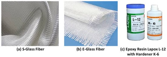
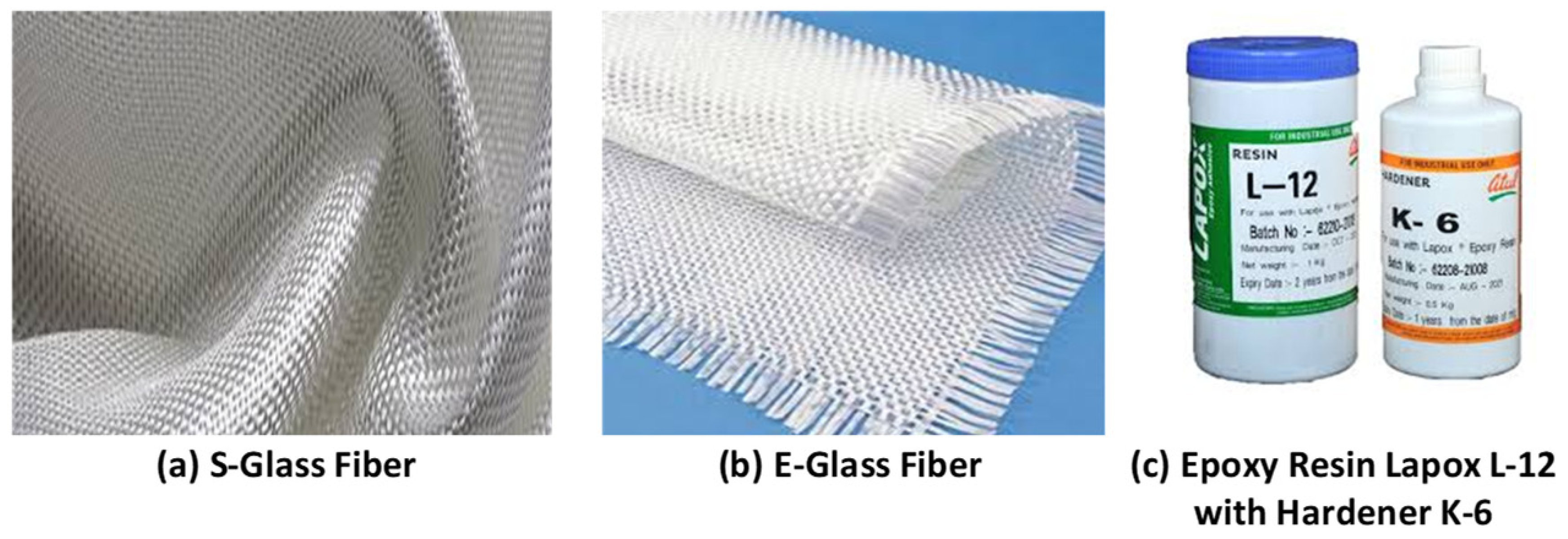
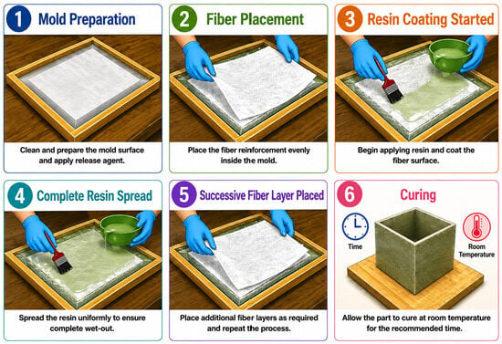
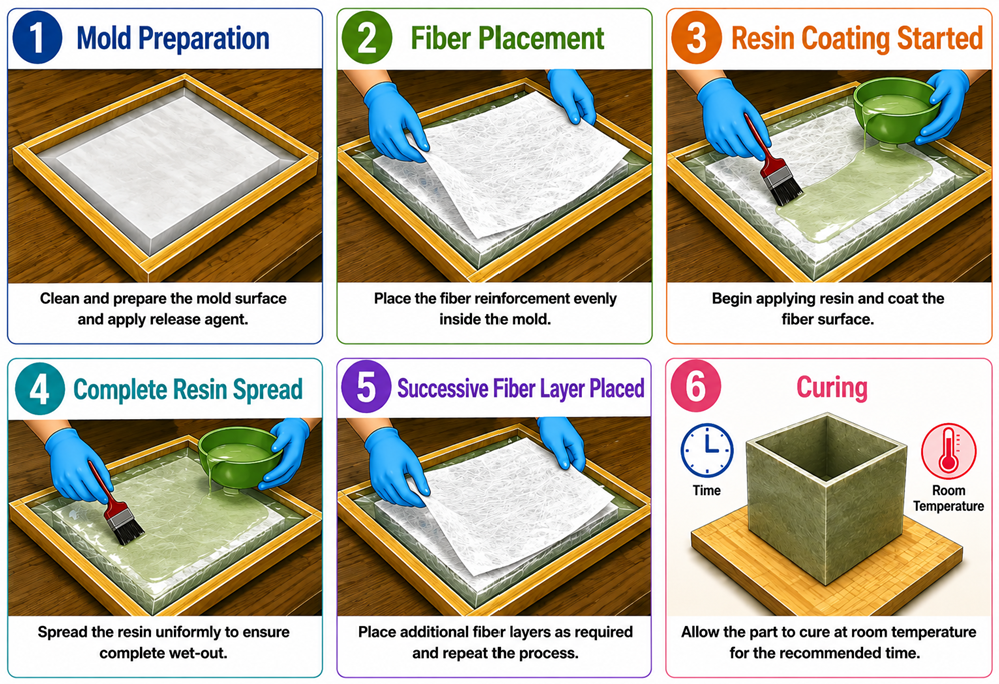
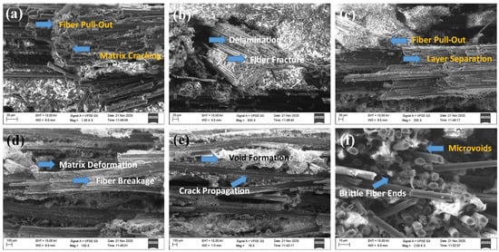
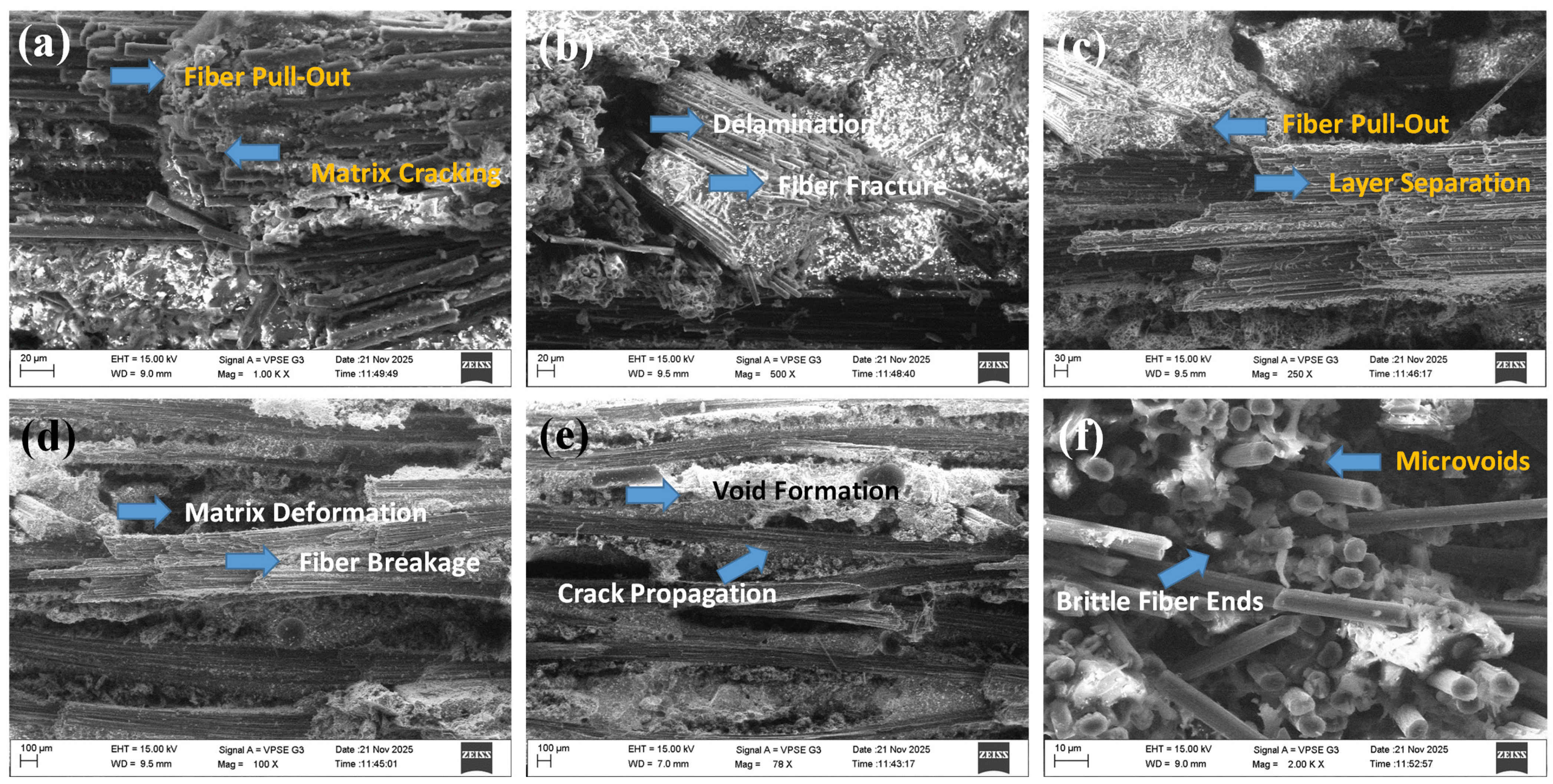
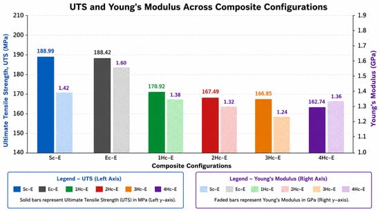
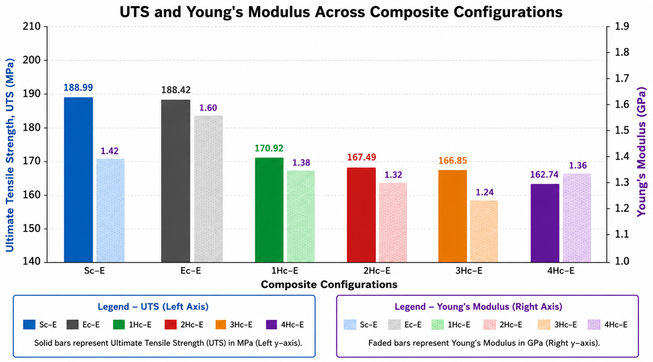
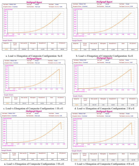
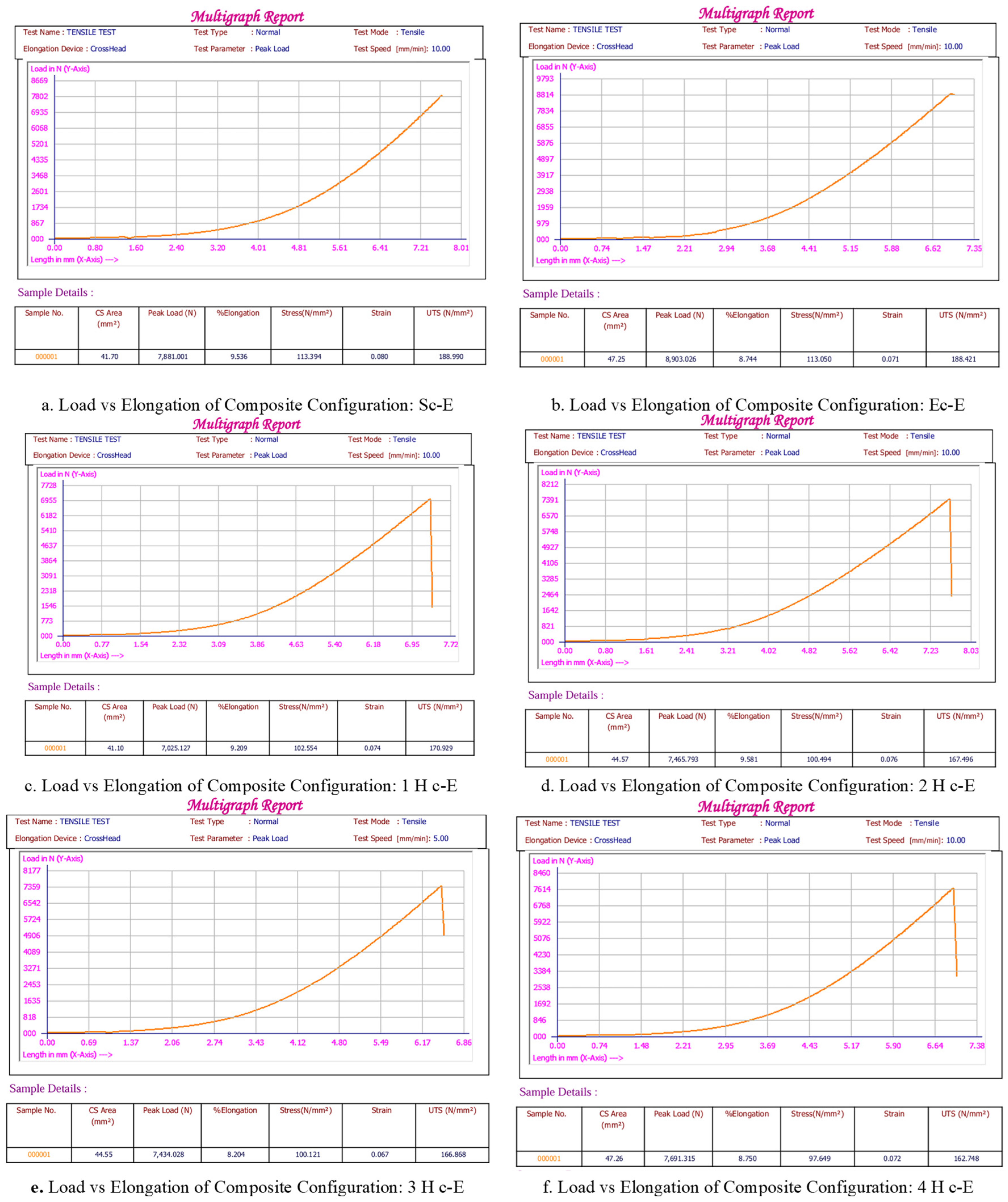
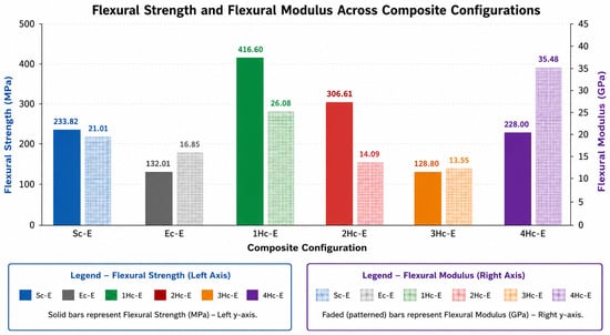
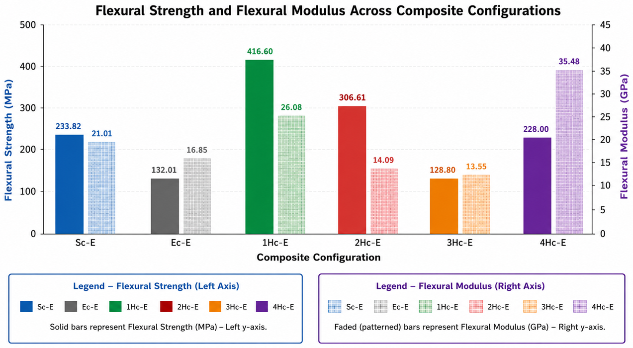
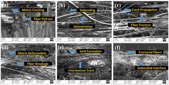
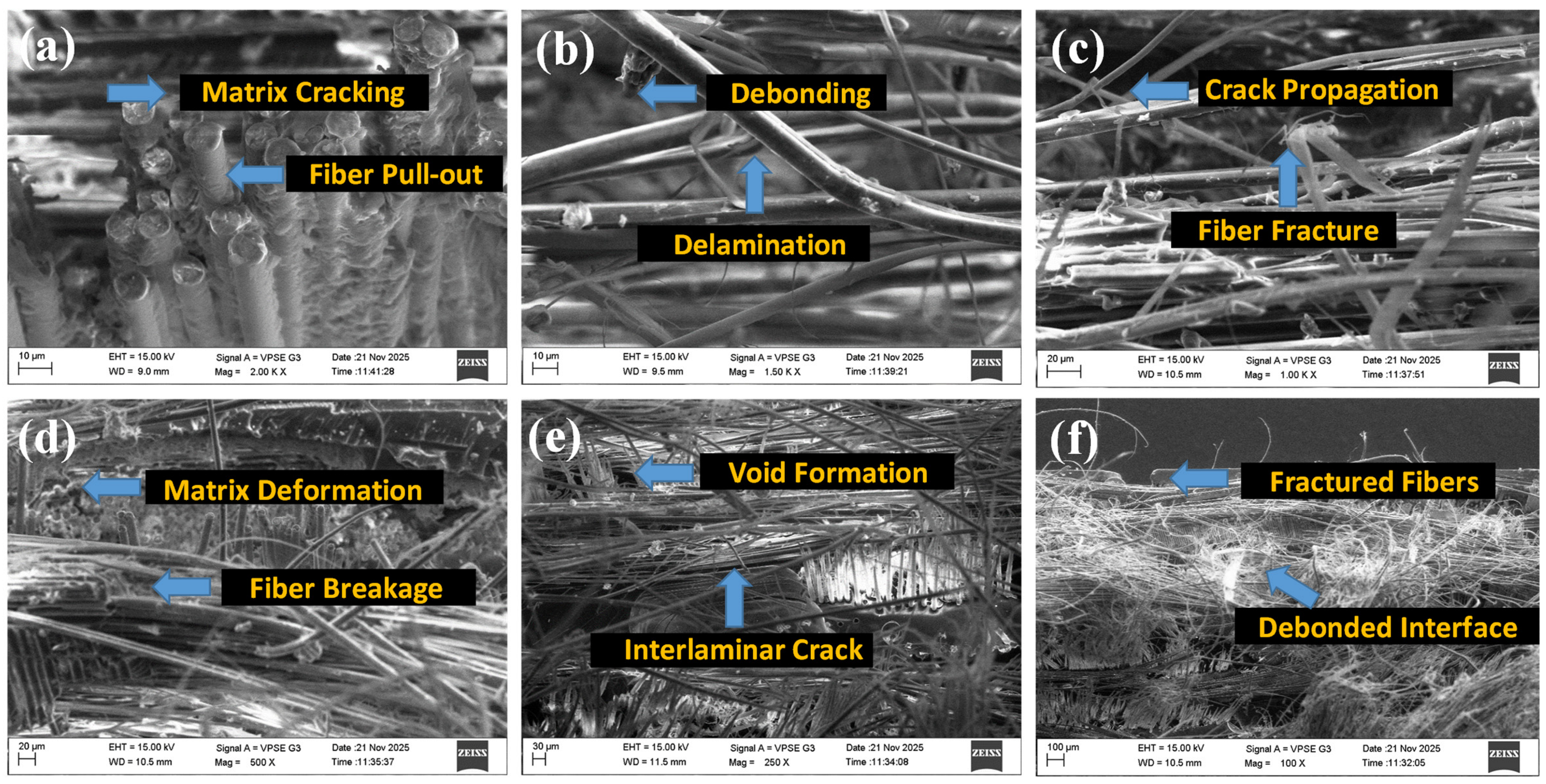
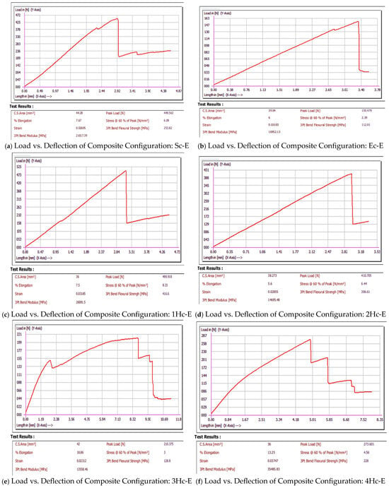
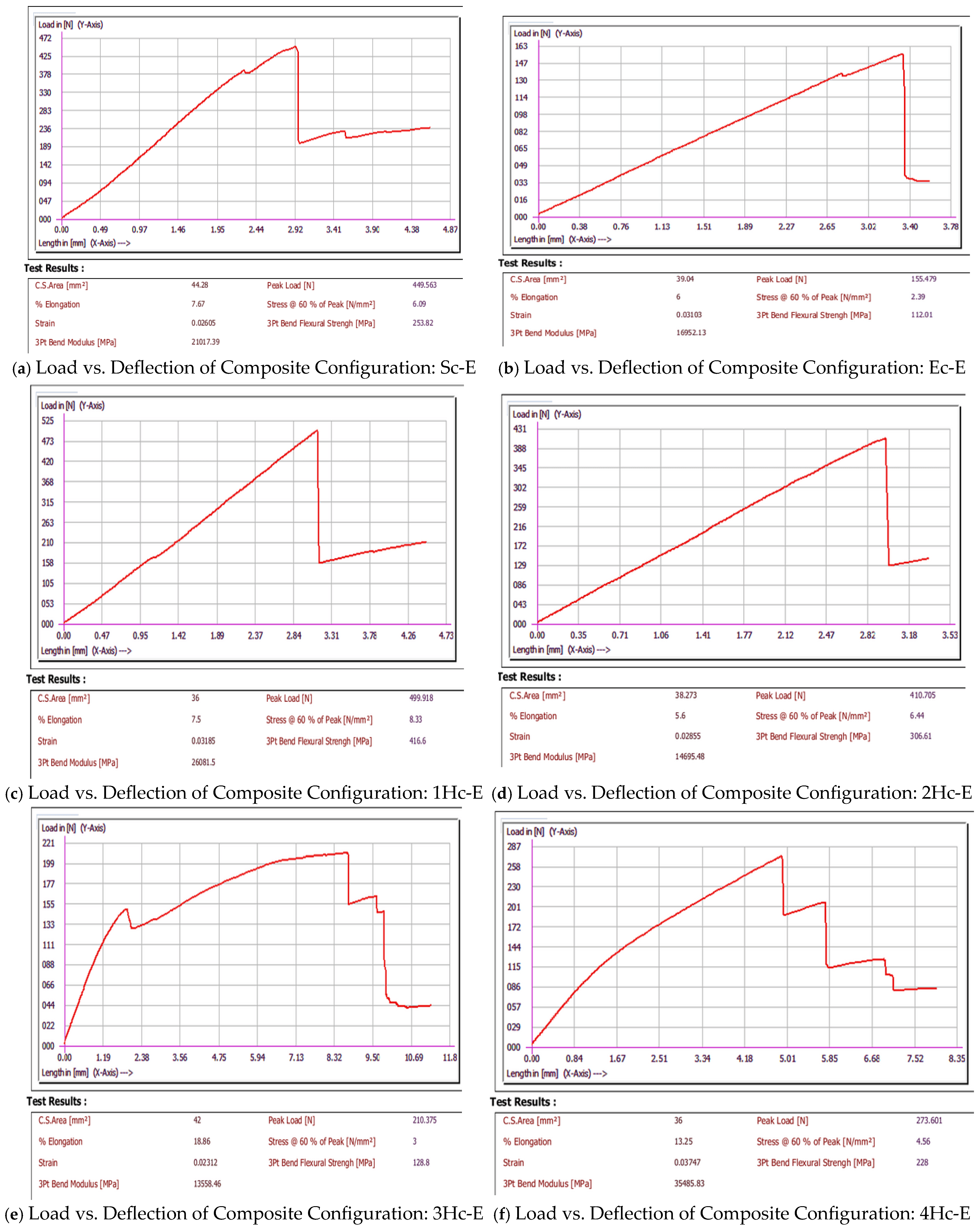
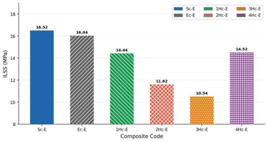
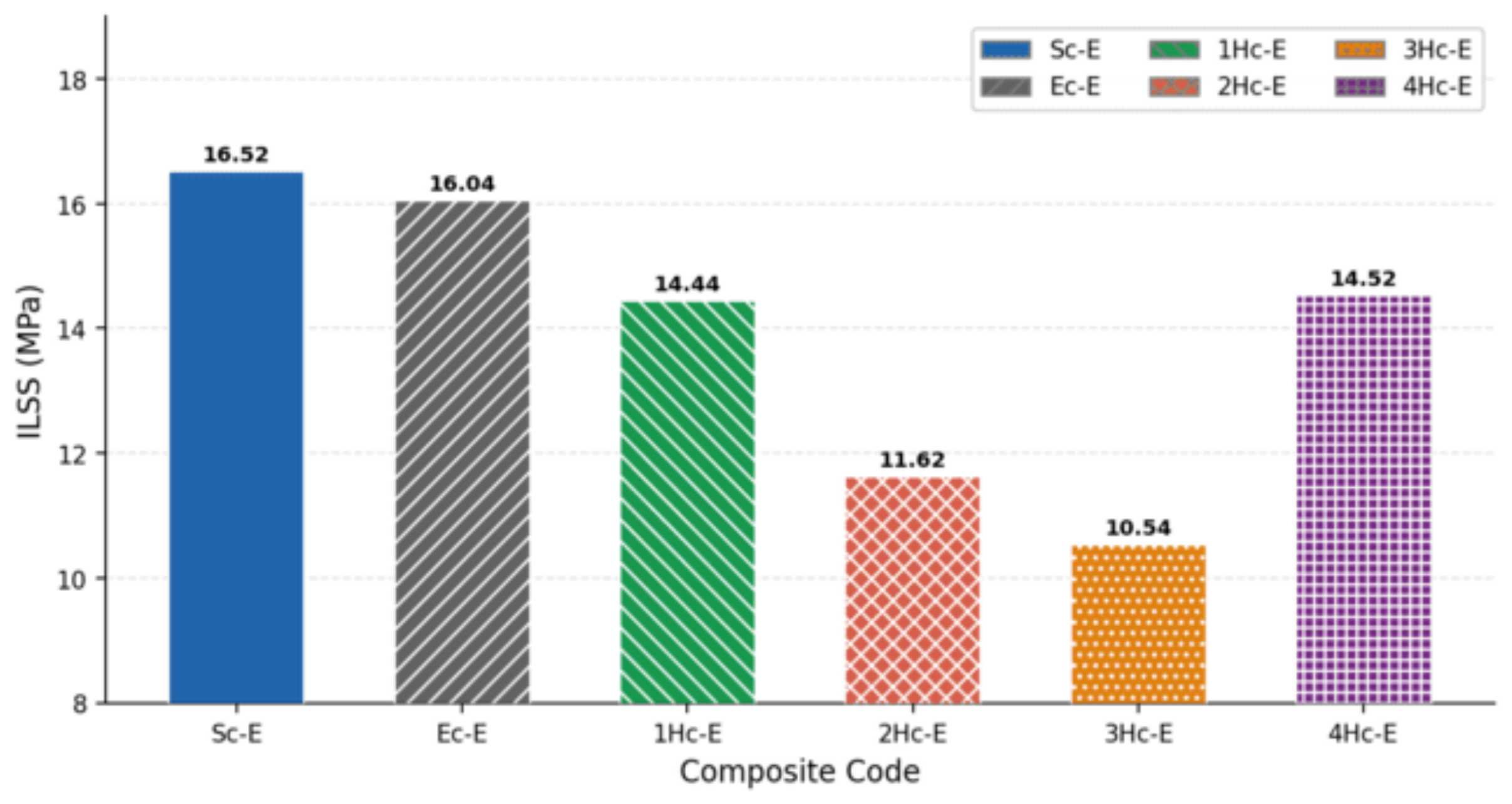
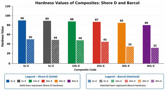
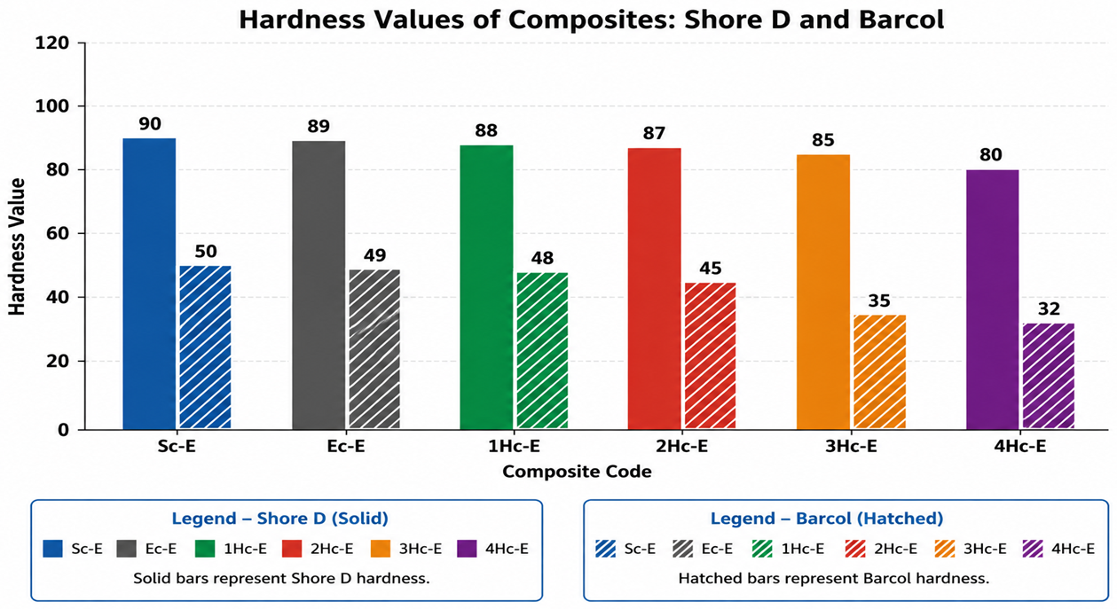
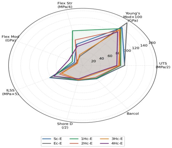
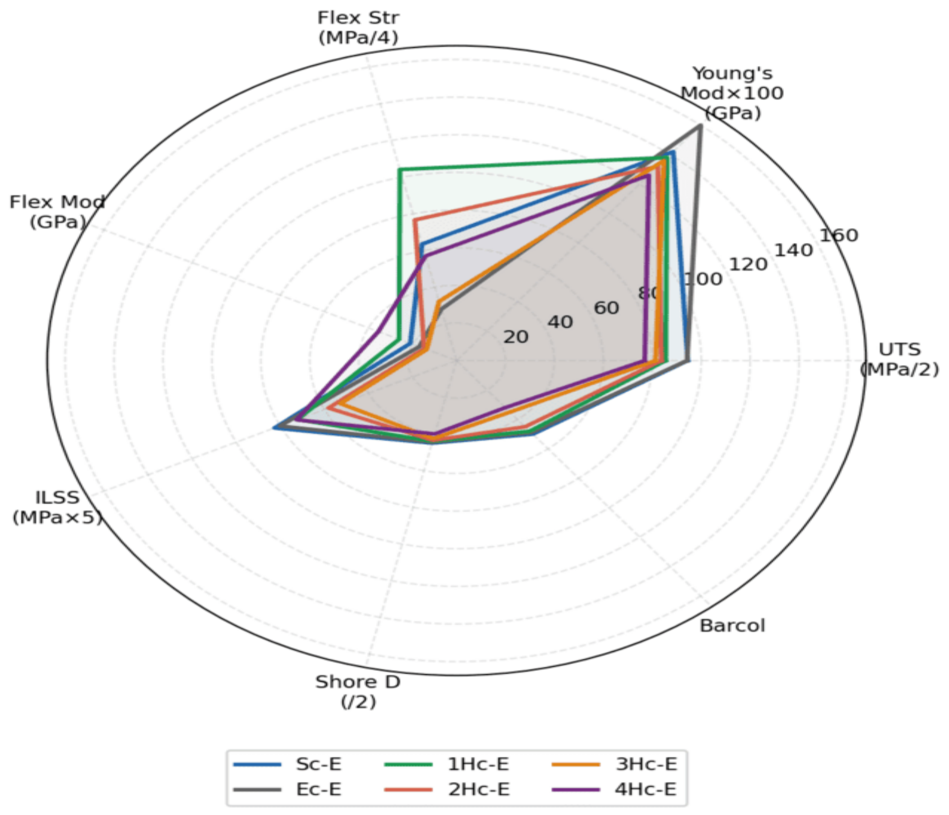

Disclaimer/Publisher’s Note: The statements, opinions and data contained in all publications are solely those of the individual author(s) and contributor(s) and not of MDPI and/or the editor(s). MDPI and/or the editor(s) disclaim responsibility for any injury to people or property resulting from any ideas, methods, instructions or products referred to in the content. |
© 2026 by the authors. Licensee MDPI, Basel, Switzerland. This article is an open access article distributed under the terms and conditions of the Creative Commons Attribution (CC BY) license.