


Abstract
Electrospinning is a versatile technique for producing membranes composed of submicrometric fibers and possessing high porosity and a large surface-to-volume ratio. These properties make electrospun fiber mats attractive for many applications including filtration, biomedical materials, and sensing. While conventional set-ups readily generate randomly oriented nonwovens, many applications require precise control over fiber organization. Such control can be achieved by manipulating the charged jet and the residual charges retained by deposited fibers, both governed by the electric field that is intrinsic to the electrospinning process. This review examines strategies for electrostatic control of electrospun fiber mat morphology, organized around two principal mechanisms: control of the charged jet in-flight and control of the landing jet. Auxiliary electrode-assisted electrospinning, which aims to suppress or redirect the whipping instabilities, as well as gap-separated and structured collectors that exploit electrostatic template effects, are discussed. Particular attention is given to the underlying mechanisms. Collectively, these methods illustrate how tailoring the electric field allows for the production of membranes with complex, application-specific fiber morphologies.
1. Introduction
Electrospinning is a fiber-producing technique that has received substantial attention from researchers over the past 30 years. This versatile technique allows for the generation of micro- and nanosized fibers from a wide range of materials, including metals, ceramics, and, most commonly, polymers [1,2]. The resulting fiber mats possess several properties that distinguish them from other materials, notably due to the small size and continuity of their constituent fibers.
Electrospun fibers can be produced with an average diameter as low as a few tens of nanometers, which leads to very high porosity and a large surface-to-volume ratio for electrospun mats. Moreover, the small size of these fibers leads to another advantage in terms of mechanical properties. Tensile strength and modulus tend to improve with decreasing fiber diameter, which is a result of enhanced molecular chain orientation along the fiber [3,4]. As such, electrospun fibers have been investigated in many applications, including filtration [5,6], biomedical materials [7], catalysis [8], sensors [9], and reinforcements [10].
Typically, the electrospinning process generates nonwoven fiber mats where fibers are oriented in a random manner. Such membranes are interesting as filtration media given their high porosity and low fiber diameter [6]. They have also been frequently used in biomedical applications since they resemble the extracellular matrix and other fibrous tissues in the human body [11,12]. However, certain applications favor a specific arrangement of fibers in the membranes. For instance, structures of tissues located at the interface of ligaments and bones have been shown to have a gradient morphology that cannot be achieved with simple nonwovens [13,14]. Electrospun membranes with controlled morphology have been developed to meet such challenges. For biomedical applications, uniaxially aligned fibers have been shown to direct cell elongation and orientation by providing contact guidance [15], while membranes with patterned morphology possess a topography that resembles native tissue even more closely [16,17,18]. Moreover, membranes composed of aligned fibers have higher modulus and strength in the fiber direction compared to isotropic properties of randomly oriented fibrous membranes [3]. As such, they can serve as light-weight reinforcements that provide a tailored mechanical response [10,19].
Over the past decade, considerable effort has been dedicated to the production of patterned electrospun mats. Near-field electrospinning provides a high level of control over the fiber deposition by exploiting the straight jet region of electrospinning. However, several drawbacks such as complex set-up, low fiber production rate, and micrometric size of fibers limit its widespread adoption [20]. Several reviews have addressed fiber alignment and patterning in electrospinning. For instance, Robinson et al. provided a comprehensive comparative analysis of fiber alignment methods, systematically classifying techniques by the physical principle exploited (mechanical, electrostatic, and hybrid) and evaluating their relative performance [21]. Moreover, the review by Liu et al. covered a range of studies on controlled fiber deposition used for biomedical applications [22]. The present review differs in scope and focus, concentrating specifically on controlled fiber deposition achieved through electrostatic mechanisms. In particular, it distinguishes between electrostatic control of the jet during flight, via auxiliary electrodes, and control of the deposition pattern at the collector, via patterned collector geometries. This review further incorporates the most recent developments in the field not covered in earlier reviews, and places particular emphasis on the underlying electrostatic principles that unify these deposition-control strategies.
The literature discussed in this work was identified through searches in Web of Science and Google Scholar, using combinations of the keywords “electrospinning,” “fiber alignment,” “fiber deposition control,” “auxiliary electrode,” and “patterned collector,” restricted primarily to publications from 2016 to 2026, with earlier seminal studies included where relevant to the development of a given technique. Publications were included if they addressed electrostatic mechanisms for controlling jet trajectory or fiber deposition pattern, therefore studies concerned primarily with fiber composition, functionalization, or biological performance were excluded.
2. Electrospinning Process
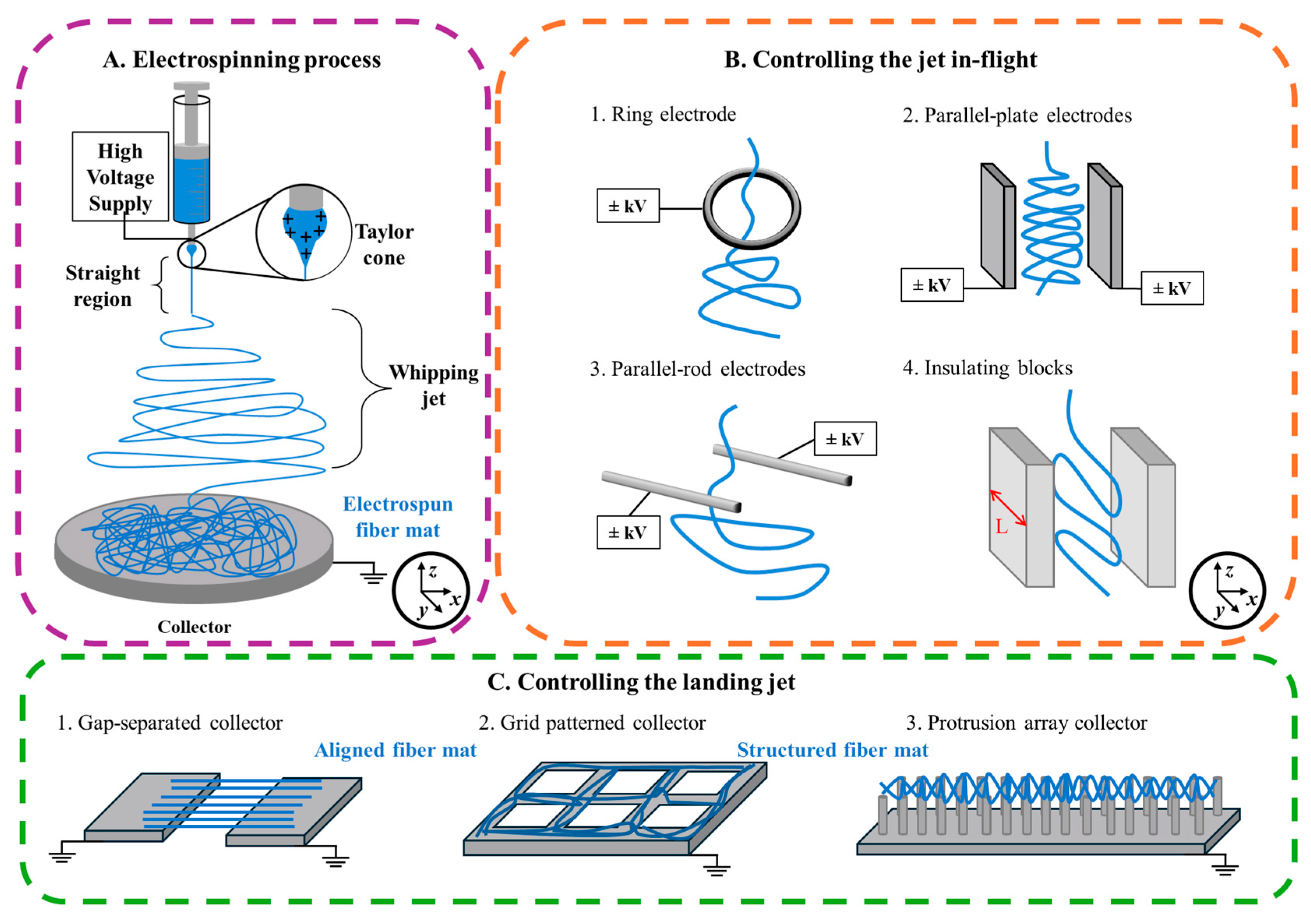
A typical set-up for solution-based electrospinning consists of a syringe containing the polymer solution connected to an emitter, usually a needle, a collector placed at a distance from the emitter, and a high-voltage power supply that establishes the potential difference between them, with the collector typically grounded (Figure 1A). The polymer solution is passed through the needle with a narrow orifice and a high voltage is applied to it. As a result, charges are induced on the pendant droplet of a polymer solution, which is deformed into a shape called the Taylor cone. Once the repulsive forces generated in the droplet as a result of injected charges overcome the surface tension of the solution, a jet is emitted from the Taylor cone. This jet, composed of charged polymer solution, has axial and radial velocity components and is subjected to the electric field induced during the process.
Figure 1.
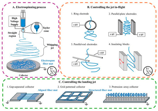
Principle of electrospinning (A) and strategies used to control the electrospun jet: in-flight (B) and during landing (C).
In-flight, the jet is stretched as the like charges repel each other, while the continuity of the jet is maintained by the entanglement between polymeric chains. The jet is subjected to several phenomena concurrently as it flies toward the collector, along the electric field. First, the jet travels in a nearly straight line, through a region called the near-field [23]. In this region, the viscosity and the surface tension of the jet are sufficient to resist the electric field and maintain its straight trajectory. However, as the jet accelerates toward the collector, its diameter decreases giving rise to electrohydrodynamic fluctuations. These fluctuations, combined with the repulsive forces between charges within the jet, then trigger a bending instability, causing the jet to bend in the form of a coil, also known as whipping movements [24]. These instabilities lead to its extensive stretching, and lowering of its diameter, while also rapidly evaporating the solvents present in the jet.
Finally, the last stage of electrospinning is the collection of fibers that takes place as the fiber reaches the collector. When the polymers used in electrospinning have sufficiently low electric conductivity, these collected fibers still retain some of their charges [23,25]. The exploitation of these residual charges for fiber morphology control is described in Section 3.2.
The whipping or bending instability, along with charge repulsion within the jet, leads to unpredictable landing on the collector, resulting in randomly oriented fiber deposition. Consequently, an advantage of electrospinning is that even the simplest set-ups can easily generate random electrospun nonwovens. However, this same characteristic makes it challenging to control the morphology of membranes, as it requires suppressing or redirecting the whipping motion of the jet.
Typically, the most straightforward approach to fiber alignment consists of using a rapidly rotating cylinder that stretches the deposited fibers as they land on the collector, thereby preventing them from depositing in random orientation [26,27]. The remaining part of the fiber is then stretched around the collector, leading to uniaxial fiber alignment. The primary advantage of this approach is a relatively simple and low-cost set-up. Moreover, it has been shown that mechanical drawing of fibers can improve the molecular orientation within polymeric chains [4]. However, highly aligned fibers are difficult to obtain with rotating cylinders, and a reduced collection area is required for better alignment, which limits the scalability of the technique [21]. Moreover, this approach does not easily allow for the preparation of more complex fiber morphologies. For instance, a cross-aligned fiber pattern can be generated by manually rotating the collector, or the already-deposited fiber mat, and repeating the electrospinning process [28].
Currently, in the literature, there are two strategies to control the deposition of electrospun fibers through the modification of electric field, which can be broadly categorized as (i) control of the charged jet in-flight and (ii) control of the landing jet. Some examples of these methods are summarized in Figure 1.
3. Strategies to Control the Electrospun Jet
3.1. Controlling the Jet In-Flight
The control of the charged jet during its flight from emitter to collector is one of the earliest examples of morphology control in electrospinning. In the pioneering work, Jaeger et al. introduced an auxiliary ring electrode (Figure 1(B1)) positioned concentrically near the emitter in a conventional electrospinning set-up [29]. When the ring and emitter were held at similar potentials, an electric field-free space was generated near the emitter, which suppressed corona discharge at the Taylor cone for viscous polymer solutions. Importantly, this configuration also established a more stable electric field between the ring electrode and the collector, which was no longer affected by the fluctuating shape of the jet base at the capillary tip. Building on this concept, Deitzel et al. employed multiple ring electrodes acting as electrostatic lenses to focus the electric field lines to the center of the collector [30]. The electrospun jet was thereby “funneled” into the center of the rings, while its whipping instability was dampened by the field imposed by surrounding electrodes. In this work, the authors concentrated the deposition of 10 wt.% poly(ethylene oxide) (PEO) solution in water into a circle with a diameter of 1 cm, in contrast to a 7 cm circular membrane achieved with conventional electrospinning. By rotating the collector, the deposition was further narrowed to a strip of 0.6 cm.
Similar logic can be applied to various auxiliary electrode geometries. Wu et al. demonstrated that adding three parallel auxiliary counter electrodes behind a rotating-drum electrospinning collector converges the electric field to focus the charged jet, thereby narrowing the width of the poly(ε-caprolactone) (PCL) fiber mat down to 2.2 cm and increasing fiber alignment from 19.6% to 72.5% [31]. Likewise, Arras et al. placed two plate-like auxiliary electrodes in parallel around the emitter, and by applying a potential of the same polarity as the needle, constrained the whipping instability experienced by the jet (Figure 1(B2)) [32]. As a result, the fibers collected on a rotating collector exhibited an enhanced degree of alignment compared to the same experiment without parallel-plate electrodes.
These early examples establish the foundational concept of auxiliary electrode-assisted electrospinning. During electrospinning, the jet exhibits axial and lateral velocity components that together describe its displacement [33]. The axial component (along the z-axis) corresponds to the motion of the jet from emitter to collector. Lateral velocity components in the x–y plane account for the sideways displacement of the jet as it undergoes whipping (bending) instabilities, following a coiling path. By modifying the external electric field, the objective of auxiliary electrodes is to suppress or dampen whipping instability experienced by the jet and thereby to provide better control over the fiber deposition area and its size.
The works that followed were aimed to improve the control over the electrospun jet and achieve narrower fiber deposition. For this purpose, Nurfaizey et al. studied the deviated deposition of electrospun fibers caused by the potential of auxiliary electrodes [34,35]. Using a pair of parallel rod electrodes placed alongside the jet’s flight path, they demonstrated a linear relationship between the voltage difference applied across the auxiliary electrodes (of the same polarity as the emitter) and the deflection of the deposition spot along the x-axis, with the spot moving away from the higher-voltage electrode (Figure 1(B3)). The authors also demonstrated that the aspect ratio of the deposition depends on the lower of the two potentials supplied to the electrodes. Increasing this base potential produced a “squeezing” effect that reduced the aspect ratio as lateral electric field constrains the whipping instability, yielding a narrower, more elliptical deposition compared to the near-circular spot obtained with grounded electrodes. These observations were confirmed using finite-element analysis (FEA) [35].
The geometry and configuration of the auxiliary electrode are other essential factors in the control of the charged jet. Neubert et al. further developed the configuration with ring electrodes by introducing a guard electrode (metallic disc fixed around the emitter) and with this addition, successfully reduced the fiber deposition area to a circle of 3–4 mm in diameter. Moreover, by collecting the fibers on a moving collector, fiber lines as narrow as 158 µm were generated [36]. The application of voltage is not always necessary for auxiliary electrodes to have an effect. It was reported that, in the case of an unpowered multi-ring electrode set-up, fibers that are deposited on the electrodes during the initial moments of electrospinning turn the unpowered rings into self-charged auxiliary electrodes [37]. This logic is also seen in the case of an apertured insulating board or by using a dielectric plastic mask placed on top of the collector [38,39]. The set-up used a coaxial emitter, with the polymer solution flowing through the central channel and pressurized air through the surrounding sheath, funneling the jet through the aperture of the insulating plate. Continuous electrospinning leads to charge accumulation on the dielectric walls of the aperture, which spontaneously forms an auxiliary “electrode” carrying charges of the same polarity as the jet. This focusing field exerts a lateral electric force on the jet, suppressing its whipping and confining the deposition area. This approach decreases the deposition area down to 3.0–4.0 cm2.
Other works have focused on the fabrication of patterned membranes by controlling the jet with auxiliary electrodes. Soldate and Fan developed a set-up employing six auxiliary electrodes positioned in a radially symmetric arrangement along the flight path of the jet, enabling deposition control through active electrohydrodynamic deflection [40]. Each electrode was independently controlled with a voltage oscillating between 0 and 5 kV at a defined frequency. Deflection was achieved by switching each electrode between ground, which attracts the positively charged jet, and high voltage, which repels it. When all electrodes were activated simultaneously without oscillation, they acted as an electrostatic lens, focusing the deposition of fibers to a spot as small as 1 cm. By selectively activating electrodes one after another in a defined phase order, the authors steered the charged jet to create well-defined macroscopic geometries, including triangles, stars, hexagons, and circles. The pattern size could be further reduced by increasing the pulsing frequency, decreasing the deposition diameter down to 7.5 mm at 45 Hz.
In a recent study, Lee et al. reported a comprehensive investigation of multi-ring electrode arrays [37]. Several geometric parameters, such as the ring electrode diameter, inter-ring distance, the position of the rings relative to the nozzle or the collector, the voltage applied to the auxiliary electrodes, and the nozzle diameter were investigated through FEA and experiments. As such, it was possible to achieve the controlled deposition area with diameters ranging from 2 to 10 cm in a single-nozzle system. Moreover, the authors extended this concept to a three-nozzle electrospinning system. In multi-nozzle set-ups, a common issue is the deviated trajectory of charged jets caused by the mutual repulsion of their like charges. By arranging three optimized multi-ring arrays together with a collector capable of translating in the XY-plane and rotating about the Z-axis, the authors focused the trajectory of each jet simultaneously, reducing the fiber deposition area to as low as 3.54 ± 0.21 cm2 and producing customized multilayer 2D shapes. Nevertheless, as in the case of previous auxiliary electrode-assisted techniques, the resolution of this method is constrained by its spot size, which is too large for fine control of deposition.
Hwang et al. achieved the greatest control over the electrospun deposition by using insulating blocks of acrylic plastic, instead of charged electrodes, to suppress the whipping motion in the charged jet in the x-direction (Figure 1(B4)) [41]. The complete restriction of the whipping movement from xyz- to yz-plane is a crucial aspect of this work. As a result of this, the jet lateral movement is confined to its y-axis, while constantly travelling downwards in the z-axis. In contrast, in previously shown examples with ring or parallel-plate electrodes, the whipping is never suppressed completely along the x- or y-axis, with only the extent of whipping being reduced [30,31,32].
The presence of insulating blocks modifies the electric field, deforming it in the inter-block region and thereby confining the jet to the space between the blocks. By contrast, the field along the y-axis does not exhibit this confinement, owing to the electric field that persists outside the block boundaries. The size of the insulating blocks (denoted as L in Figure 1(B4)) plays a crucial role, as blocks extending beyond the collector disrupt controlled fiber deposition. In addition, the z-component of the field at the center decreases within the inter-block region and exhibits a small minimum, reducing the downward pull so that the confined jet is governed mainly by the Coulombic force of its intrinsic charge. As a result, the first whipping instability experienced by the jet is biased toward the y-axis, and the resulting self-repulsion of the jet restricts the subsequent whipping motion to the yz-plane. In contrast, a ring or parallel-plate electrode held at the emitter potential produces an axially symmetric field around the jet, imposing little or no directional bias, and, consequently, the whipping is not confined to a single plane [29,36,42].
Among these strategies, insulating block-assisted electrospinning stands out by enabling the controlled deposition of individual fibers, achieved by continuously translating the collector during deposition, with inter-fiber spacing that can be tuned with the translation speed down to 5 µm. Furthermore, by rotating the collector during the process, electrospun membranes composed of cross-aligned fibers can also be generated. Owing to this precise structural control, the technique has been successfully exploited to produce membranes for applications ranging from air filters to fuel cell membranes and zinc-air batteries [19,43,44]. Collectively, these examples demonstrate that tailoring the electric field around the charged jet, whether through powered electrodes or insulating elements, remains a versatile route to controlling fiber deposition in electrospinning.
3.2. Controlling the Landing Fiber Jet
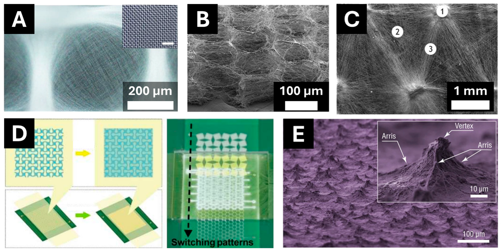
Another approach is directed toward controlling the landing of fibers on the collector. Upon landing, the fiber jet still carries charges; however, as mentioned earlier, these charges are not mobile due to the dielectric nature of most of the polymers used in electrospinning. Various collector geometries were designed to exploit the presence of residual charges on fibers and to generate electrospun membranes with controlled morphologies (Figure 2).
Figure 2.
Various patterns achieved through electrospinning on structured collectors. (A) Grid-like structure obtained by electrospinning on a metallic wire mesh. Adapted with permission from [45]. Copyright 2023, MDPI. (B) Honeycomb-patterned structures obtained through electrostatic template-assisted deposition. Adapted with permission from [46]. Copyright 2018, American Chemical Society. (C) Heterogeneous fiber deposition achieved by electrospinning on an array of protrusions. Adapted with permission from [47]. Copyright 2021, American Chemical Society. (D) Pattern switching method used to fabricate membranes with changing patterns. Reprinted with permission from [48]. Copyright 2025, American Chemical Society. (E) Self-assembled pyramid-like structures. Reprinted with permission from [49]. Copyright 2022, Springer Nature.
3.2.1. Gap-Separated Collectors
Li et al. demonstrated that electrospinning of poly(vinyl pyrrolidone) (PVP) solution on a gap-separated collector yields highly aligned fibers that are suspended across the gap (Figure 1(C1)) [50]. The alignment mechanism is governed by electrostatic interactions between charged fiber segments and the nearest regions of the collector. As a charged fiber segment approaches the grounded collector, charges on the fiber induce image charges of opposite polarity on the collector surface. The resulting Coulombic attraction increases as the separation distance between fiber and collector decreases. In the vicinity of the gap between the electrodes, different regions of the fiber segment are attracted toward the nearest electrode edges, generating tensile forces that stretch and align the fiber across the gap. Furthermore, because the stretched fiber segment remains suspended in air rather than being in direct contact with the grounded collector, it cannot readily dissipate its residual charge. The retained charges on the suspended fiber electrostatically repel subsequently arriving fibers, promoting their deposition at a distance from previously deposited fibers. This mutual repulsion contributes to the formation of a highly aligned array of fibers spanning the electrode gap. It should also be noted that random deposition of fibers still takes place on the surface of the collectors.
The strength of this alignment is therefore directly governed by the magnitude of the surface potential, which is the electric potential measured above the charged fibers suspended over the gap, arising from the charges that are not dissipated to the grounded collector. In the work of Liang et al., electrospinning poly(lactic acid) (PLA) over a 3 mm gap for 50 s generated a surface potential of ~1500 V, which in turn produced highly aligned fibers with a standard deviation of only 12° from perfect alignment [51]. In contrast, electrospinning poly(ethylene oxide) generated a lower surface potential of ~270 V, resulting in poorer alignment (23°). The lower surface potential was attributed to the higher conductivity of PEO fibers, which leads to faster charge dissipation. Finally, a mixture of PEO with the polyelectrolyte alginate led to a surface potential below 10 V and showed essentially random deposition, as fibers became even more conductive. However, the alignment in the case of gap-separated collectors does not continue indefinitely due to accumulation of fibers across the gap, which leads to eventual dissipation of charges. As the surface potential across the gap decreases, the electrostatic template effect weakens, and fibers begin to deposit in random orientations, as in conventional electrospinning [25].
Several variations in the gap-separated collector were reported over the years. Park and Yang modified the gap-separated collector to include an inclination formed by placing one conductive strip horizontally and the other vertically at a lower position [52]. This resulted in an asymmetric electric field that caused fibers to deposit sequentially, first on the upper edge, then stretching to the lower edge of the collector. This time difference between the deposition of different fiber segments allowed more time and space for the self-alignment through electrostatic repulsion from other pre-deposited fibers, yielding PCL fibers with a higher orientation parameter (0.96) compared to conventional planar gap (0.65–0.9) or rotating drum (up to 0.8) methods. Building on the inclined-gap concept, Hsu et al. introduced serrated teeth-like structures along the edges of an inclined gap collector to enable the simultaneous collection of multiple piezoelectric PVDF-TrFE fiber bundles [53]. The sharp tooth tips acted as preferential charge-dissipation points, shaping the electric field so that fibers aggregated and bridged the closest pair of directly opposing teeth across the gap. Both finite-element simulations and experiments showed that a sharp tooth angle combined with short pitch and gap distances produced the best-defined, independent fiber bundles. However, electrospinning duration had to be short, kept below 60 s, to preserve the fiber alignment.
All the collectors in the previous examples were grounded. Grounding maintains the collector at zero potential, so that the electric field between the emitter and the collector is determined solely by the potential applied at the emitter. Applying a non-zero potential to the collector allows for greater control over the potential difference, and therefore the field strength and field distribution, between the emitter and the collector, independently of the emitter voltage. This additional degree of freedom can be used not only to enhance the electrostatic force acting on the charged jet, but also to reshape the field lines and thereby modify the deposition pattern. Lei et al. demonstrated that applying a negative potential to a pair of gap-separated parallel plates can be used to substantially extend the length of aligned fibers, producing poly(vinylidene fluoride) fibers up to 125 cm in length [54]. The key insight of this study is that the plate depth (along the jet travel direction) and thickness are essential for achieving fiber alignment across such a large gap. A sufficient depth is required to suspend the jet across a wide gap, below which the fibers deposit randomly rather than spanning between the plates. Moreover, the negative potential not only attracts the positively charged jet across the gap but also continues to act on the deposited, suspended fibers, pulling their charged segments toward the plates and thereby straightening and aligning them.
All these examples demonstrate that electrospinning on gap-separated collectors is an efficient method to generate aligned electrospun fibers. However, while some studies demonstrate the preparation of cross-aligned fiber mats by rotating the collector [50,55], the production of more complex structures is not yet feasible with this technique.
3.2.2. Structured Collectors
The geometry used for gap-separated collectors consists of a pair of parallel electrodes with sufficient length and separation between them. Modification of the gap geometry can alter the fiber deposition, for instance, by using gap-separated circular or rectangular electrodes, fibers aligned in multiple directions are generated [56]. This concept was extended to collectors with a controlled topography or consisting of conductive/dielectric paths, in order to generate electrospun membranes with morphologies controlled at a smaller scale [57,58,59,60,61]. Li et al. demonstrated this effect, for the first time, by performing electrospinning on a quartz wafer patterned with gold [62]. Upon electrospinning, PVP fibers preferentially deposited on gold-coated parts of the collector, while dielectric parts were covered by fewer fibers. In fact, the first fibers deposited on such a collector form an electrostatic template based on the hindered charge dissipation from the fibers. Zucchelli et al. demonstrated that enamel, a dielectric material, can be used to generate patterned membranes by doping it with conductive additives such as montmorillonite clay particles or by adding alumina particles or graphite on the surface [63]. The heterogeneous material distribution on the surface generates an electrostatic template similar to the previous example and leads to fiber patterning. Therefore, charge retention in fibers can be achieved either through fibers suspended in air or through fiber segments insulated on a dielectric material.
Various patterns can be designed for structured collectors resulting in highly customizable fiber mat morphologies. For instance, by placing a long, narrow strip of a conductive material between large dielectric areas, fibers can be aligned along the length of the strip [62]. Fibers can also be radially aligned by placing a small conductive area in the hollow of a larger conductive disc [64,65]. Common collectors used for generating structured mats include conductive patterned electrodes or wire meshes (Figure 1(C2)) [45]. Patterned electrodes exploit the presence of conductive patterns as well as air gaps to structure the fiber deposition. As the first fibers are deposited on the entire surface of the collector, certain segments are stretched over the gaps in the pattern. Similar to the case of gap-electrospinning, these fiber segments do not release their charges, effectively creating an electrostatic template built by the regions with higher surface potential (suspended fibers) and low surface potential (fibers on the conductive surfaces) [51]. The incoming, charged jet is therefore subjected to attractive/repulsive forces due to the presence of this template and its deposition is guided toward the attractive regions. Various fiber mat morphologies have been reported using electrostatic template-assisted electrospinning, including but not limited to hexagonal or honeycomb, re-entrant honeycomb, circular, square, grid-like, and parallel line structures [16,60,66,67,68]. One of the examples can be seen in Figure 2A. Moreover, this approach has been reported in the fabrication of layered honeycomb-patterned fiber–particle composites (Figure 2B) [46].
The problem related to the electrostatic template and structured collectors is the gradual saturation of the template. As electrospinning proceeds, an increasing number of fibers accumulate on the attractive regions of the collector, raising the surface potential in these areas, while the suspended strands bridging the gaps initially retain their charge and sustain the high-potential, repulsive zones of the template. As deposition continues and fibers cross the gaps, the growing number of fiber–fiber contacts lowers the resistance of the suspended network, allowing these segments to release their charge and reducing their surface potential [69]. As a result, the difference in electric field intensity between attractive and repulsive areas diminishes over time, weakening the template effect and eventually leading to random fiber deposition. One strategy to prolong the template effect consists of introducing electrosprayed particles during fiber deposition. Electrospraying uses the same set-up as electrospinning but generates particles rather than fibers, typically owing to the lower molecular weight or lower concentration of the processed polymer [70]. Because these particles carry the same charge polarity as the fibers, they are also guided by the electrostatic template. Once deposited on the attractive regions, the particles improve the electrical contact between fibers and with the collector protuberances, both through the number of contacts they provide and, in some systems, through their higher residual-solvent content, which can enhance contact quality by partially embedding the fibers. This improved interconnection promotes charge release through the fibrous bundles, helping to maintain the electrostatic template for longer production times. This approach, called electrostatic template-assisted deposition (ETAD), has been reported to increase the thickness of the structures that can be generated before the template is lost [67].
Another common geometry is a collector consisting of an array of protrusions [47,57,58,71]. In the work of Terranova et al., composite scaffolds were fabricated on such a collector via the ETAD approach for dental pulp regeneration (Figure 1(C3)) [47]. Using a 3D-printed collector composed of regularly distributed cylindrical protuberances (0.7 mm in diameter), the authors generated membranes with a heterogeneous morphology comprising three distinct zones: thick nodes of intertwined fibers and particles atop the protuberances, highly aligned fibers bridging neighboring cylinders, and sparse, randomly oriented nanofibers in the interstitial regions (see Figure 2C). On such collectors, parameters such as the height of protrusions and spacing between them are essential for generating a continuous, structured fiber mat [59]. Song et al. used a dynamic collector, which consisted of an array of needles that selectively move forward or backward to generate a thick, highly porous fibrous membrane [71]. As the electric field is strongest at sharp points, fibers were preferentially collected at the needle tips, building up a 3D structure layer by layer. However, as fiber deposition builds up, the needles are progressively moved forward to pierce the existing layer and create new attractive points, allowing continuous deposition and increasing the overall volume of the membrane. The generated membranes exhibit higher pore size, volume and interconnectivity compared to conventional electrospun mats, making them good candidates for bone tissue engineering.
Recently, Bu et al. further developed template-assisted electrospinning by connecting a square mesh patterned collector to the ground and imposing the same potential as the emitter on the hollow areas of the collector [66]. This is achieved by including an additional auxiliary electrode separated from the patterned collector by a thin insulating layer. This way, no fibers are deposited over the holes in the pattern, instead being constrained to deposit on the patterned collector. This approach exploits the advantage of patterned collectors in terms of morphology control while using an auxiliary electrode to enhance the template effect. This approach was also extended to triangle and circular mesh collectors. An insulating layer was also used by Ding et al. [48]. In this case, the patterned electrode was placed below an insulating, polyimide film that acted as a substrate for fiber collection. Moreover, the set-up was built in such a way that the patterned collector could be changed during the electrospinning process, leading to the modification of deposited patterned fiber mat (Figure 2D). As such, it was possible to fabricate membranes that exhibit multiple patterns throughout their thickness. Notably, mechanical metamaterials can be generated whose Poisson’s ratio can be tuned layer-by-layer as well as multilayered films with different patterns across the thickness. Additionally, patterned electrodes were integrated into a rolling stage that allowed not only the change of pattern during electrospinning, but also depositing fiber over extended areas, opening the potential of this approach for scale-up.
It is worth noting that the alignment mechanism in electrospinning using insulating blocks, described earlier, fundamentally differs from that operating through the electrostatic template effect (i.e., using a patterned collector or based on the self-assembly of electrospun fibers). Consequently, the two approaches impose distinct requirements on the electrical properties of the electrospinning formulation. Indeed, in patterned collector electrospinning, fiber organization progressively emerges from the electrostatic template formed at the surface of the deposited fibers, which guides the incoming jet immediately before landing. Consequently, the persistence of this electrostatic template throughout the deposition process is critical for maintaining alignment during prolonged electrospinning. Such a mechanism is therefore favored when the deposited fibers exhibit high dielectric properties, allowing them to retain surface charges and preserve the local electric field distribution responsible for jet guidance [69]. By contrast, in electrospinning using insulating blocks, fiber alignment/structuration is primarily governed by the electric field experienced by the jet during its flight rather than by electrostatic interactions occurring at the collector surface. As a result, thick deposits of aligned fibers can theoretically be produced without degradation of the alignment, provided that the deposited fibers do not perturb the electric field experienced by subsequent jets. This requirement implies that electrically conductive electrospinning formulations may be particularly advantageous for insulating-block electrospinning, which represents the opposite trend to that generally reported for patterned collector electrospinning. Typical examples include aqueous polymer solutions such as PEO-based systems, polyelectrolyte and polysaccharide formulations, or solutions containing ionic inorganic precursors. These formulations generally generate highly charged electrospinning jets, as evidenced by jet current measurements reported in the literature [72,73,74], thereby increasing their sensitivity to electric field-driven guidance during flight. At the same time, once deposited on the grounded collector, the electric charges carried by these conductive fibers are expected to dissipate rapidly, thereby minimizing residual electrostatic interactions with the incoming jet. Such efficient charge dissipation may preserve the electric field distribution imposed by the insulating blocks throughout the deposition process, ultimately enabling sustained fiber alignment even after the accumulation of relatively thick nanofibrous mats. The comparison between these two strategies is summarized in Table 1.
Table 1.
Influence of formulation conductivity in the case of insulating block-assisted and electrostatic template-assisted electrospinning strategies.
In summary, structured collectors offer a versatile route to control fiber mat morphology through electrostatic template effects, enabling complex fiber morphologies that are difficult to achieve by other methods. However, few examples are available that show the scalability of this technique, limited by the template saturation and need for custom-made collectors, which are often costly and time-consuming to fabricate. In this regard, the doping approach demonstrated by Zucchelli et al., which offers an alternative way to collector fabrication compared to machining, and integrating patterned collectors on a rolling stage to enable deposition over extended areas, as shown by Ding et al., could offer ways to bypass these restrictions and scale up the process, making patterned electrospinning better suited for widespread use.
3.2.3. Self-Assembly of Electrospun Fibers
The presence of a structured collector is not always necessary for morphology control, as any variation in the surface potential on the collector can induce an electrostatic template effect. For instance, Yan et al. demonstrated the self-assembly of electrospun fibers into honeycomb-patterned nanofibrous structures as a general phenomenon, achieving it for three different polymers (polyacrylonitrile, polyvinyl alcohol (PVA), and PEO) on both conducting and insulating substrates, with pore diameters ranging from micrometers to over 200 μm [75]. They attributed this self-assembly to the competitive actions of surface tension and electrostatic repulsion acting on fibers that remain wet upon landing. Surface tension merges contacting fibers into clusters, while the increasing charge density of these clusters repels incoming fibers toward regions of lower charge. This process favors three-branched junctions approaching 120°, ultimately yielding hexagonal pores whose walls consist of uniaxially aligned nanofibers. The self-assembly occurred mainly for beaded nanofibers, since the thick bead regions retain solvent and remain wet on the substrate, which is a prerequisite for the merging and charge-driven organization to take place. Ahirwal et al. reported self-assembly of PCL fibers achieved as a result of bi-modal size distribution of electrospun fibers [76]. The inhomogeneous fiber diameter was obtained as a result of mixing two solvents, dichloromethane (DCM), a good solvent for PCL, and dimethylformamide (DMF), a poor solvent for PCL, which resulted in inhomogeneous solubilization of the polymer. Furthermore, DMF has a higher boiling point compared to DCM, which leads to thicker fibers having residual solvent upon deposition. Consequently, thicker fibers released their charges more efficiently due to superior contact with the collector and residual solvent, while thinner fibers remained suspended in air, retaining their charge. This heterogeneous charge distribution created a naturally occurring electrostatic template that drove fiber self-assembly into honeycomb patterns. Importantly, this self-assembly mechanism can be further enhanced using structured collectors, combining natural charge heterogeneity with designed membrane patterns.
As seen from these examples, the presence of thick fiber segments or beaded fibers is a necessary condition to drive the self-assembly mechanism. However, not all polymers can produce bi-modal fiber size distribution and beaded fibers usually suffer from poor mechanical properties. To bypass this restriction, Lavielle et al. used electrosprayed particles in order to induce self-assembly of fibers [77]. By electrospraying PEO particles concurrently with electrospinning of PLA fibers, self-assembled honeycomb-like composite was generated. In this case, PEO particles play the role of thick domains, where charge dissipation is facilitated, creating the non-uniform electrostatic templates that organize the fiber deposition. An additional advantage of this approach is that the pattern size could be tuned simply by adjusting the particle flow rate. Building on this principle, Flaig et al. employed the same simultaneous electrospinning–electrospraying strategy but combined it with high-speed mechanical rotation of the collector [78]. In this case, the electrosprayed particles act as electrostatically attractive sites that structure the incoming fibers and particles, while the high rotational speed simultaneously aligns the suspended nanofibers spanning these aggregates. This produced three-dimensional scaffolds combining aligned nanofibers with enlarged pores, well-suited for cardiac tissue engineering.
There are also examples of specific geometries developed using self-assembly of fibers. For instance, Yao et al. produced gradient honeycomb-patterned meshes from PCL for potential application in interface tissue regeneration [14]. By tuning the emitter-to-collector distance and applied potential, pore sizes changing gradually from 800 μm down to 300 μm were obtained on a single membrane, with the depth of these pores around 100 µm. The mechanism behind the gradient pore formation appears to be linked to the electric field, which is strongest at the collector directly opposite the emitter and decreases gradually toward the edges. As a result, more fibers are deposited in the center of the collector, leading to higher electrostatic repulsion and larger pore sizes. Similar observation was reported in other self-assembled structures, where it was linked with the gradient increase in thickness across the electrospun membrane [76,77]. This phenomenon is linked to the preferential deposition of fibers on relatively large patterns, which leads to their further growth in size and disappearance of smaller ones. This explains the gradual decrease in pore sizes toward the edges of the membrane as the thickness of electrospun deposition, typically, decreases away from the center.
Self-assembly of electrospun fibers can also generate patterns other than hexagonal ones. Zhang et al. produced a membrane having a rough top surface with pyramid-like features generated through self-assembly of beaded PVDF, PVA or thermoplastic polyurethane (TPU) nanofibers (see Figure 2E) [49]. These protrusions reached up to 300 µm in height and provided a gradient morphology to the membrane, making it suitable for application in radiative cooling, pressure sensing, and bioenergy harvesting. Comparable microstructures were reported by Shang et al. for TPU fibers, once again, for the fabrication of flexible pressure sensors [79]. The authors demonstrated that by combining the self-assembly method with a metallic wire mesh used as a patterned collector, it is possible to generate conical features reaching more than twice the height of those achieved through self-assembly on a flat collector. The two approaches yielded heights of 151.1 µm and 59.6 µm, respectively, after 5 h of electrospinning. Compared to the random placement of pyramids in the previous study, the patterned collector enables a uniform distribution of the deposited microstructures.
In summary, self-assembly of electrospun fibers offers a simple route to engineer ordered nanostructures across a wide range of geometries and materials. The underlying mechanism, which relies on the creation of an electrostatic template through the presence of residual solvents, beads, particles, or bi-modal size distribution can be naturally induced and further enhanced through patterned collectors, enabling precise morphological control for tissue engineering, sensing, and other advanced applications.
Overall, the strategies presented in this section show that the electric field can be tailored either to act on the jet while it is still in flight or to exploit the residual charge retained by the jet once it interacts with the collector. Table 2 summarizes the requirements, mechanisms, morphologies, and relative advantages and limitations of the strategies discussed above. Regarding their readiness for industrial-scale processing, these techniques differ considerably. Auxiliary electrode-assisted methods appear the most compatible with existing high-throughput approaches, as ring and parallel-plate electrodes have already been combined with needleless electrospinning on a conveyor-belt collector to enable continuous fiber production [80]. Structured and gap-separated collectors, by contrast, have mostly been demonstrated at the single-emitter, laboratory scale, and their scalability is further constrained by electrostatic template saturation and the cost and complexity of fabricating custom collectors. A notable exception is the integration of patterned electrodes into a rolling stage, which allows both pattern switching and deposition over extended areas, pointing to a possible route toward scale-up [48]. Self-assembly-based techniques, requiring no specialized collector, have good potential for scale-up on high-throughput electrospinning systems. However, this technique is limited in terms of controlled morphology (i.e., honeycomb-like or pyramidal). Overall, in-flight jet-control strategies currently show a more direct path toward continuous processing, whereas landing-jet control methods still require further development of collectors capable of sustained, large-area operation.
Table 2.
Overview of strategies for electrostatic control of electrospun fiber deposition.
4. Conclusions and Perspectives
This review has examined the strategies developed to control the morphology of electrospun fiber mats through the manipulation of the electric field intrinsic to the electrospinning process. Throughout the diverse techniques discussed, a unifying principle emerges: by tailoring the electric field, it is possible to influence the behavior of the charged jet, thereby dictating the final fiber organization. These strategies were organized around two principal mechanisms: control of the charged jet in-flight and control of the landing jet.
In the first category, auxiliary electrode-assisted electrospinning was shown to suppress or redirect the whipping instability of the jet. By employing charged ring or parallel-plate electrodes, or insulating elements, the jet trajectory can be focused and confined, narrowing the deposition area and enhancing fiber alignment. Notably, insulating block-assisted electrospinning stands out by confining the whipping motion to a single plane, enabling the controlled deposition of individual fibers with micrometric inter-fiber spacing. In the second category, control of the landing jet exploits the residual charges retained by the poorly conductive fibers. Gap-separated and structured collectors generate non-uniform electric fields that act as an electrostatic template that guides fiber deposition, allowing the fabrication of aligned, patterned, and three-dimensional architectures. Self-assembly phenomena were shown to naturally create such templates, which can be further enhanced through patterned collectors.
Looking ahead, the combination of these jet-control approaches could serve as a route toward scalable production of patterned membranes. A key challenge is that one method may interfere with another. For instance, suppressing the whipping motion of the jet was shown to hinder the preparation of long, aligned fibers [54], while focusing the deposition may accelerate the saturation of the electrostatic templates formed on structured collectors [51]. Nevertheless, Kılıç et al. demonstrated that these techniques can be paired by using a conveyor belt of gap-separated plates to collect fibers generated by needleless electrospinning, focusing the jet using parallel-plate electrodes [80].
Beyond combining existing strategies, several research directions could accelerate their maturation into robust, scalable technologies. These include quantitative models linking electric field distribution to deposition outcomes, which would reduce reliance on trial-and-error optimization; in situ monitoring and control of surface potential to counteract electrostatic template saturation; systematic studies of template stability during prolonged deposition; the adoption of standardized quantitative metrics for fiber alignment and pattern fidelity to enable direct comparison between approaches; and integration of these strategies with high-throughput, needleless or multi-nozzle electrospinning platforms.
In summary, this review illustrates how tailoring the electric field allows for the production of membranes with complex, application-specific fiber morphologies, spanning filtration, biomedical scaffolds, and sensing applications. Nevertheless, several recurring limitations persist across these techniques, including large deposition areas, the saturation of the electrostatic template and the reliance on custom-made collectors, all of which constrain the scalability and broader adoption of these approaches.
Author Contributions
Conceptualization, I.S.; methodology, I.S.; investigation, I.S.; data curation, I.S.; writing—original draft preparation, I.S.; writing—review and editing, I.S., G.S., A.H. and E.L.; visualization, I.S.; project administration, G.S.; funding acquisition, G.S. All authors have read and agreed to the published version of the manuscript.
Funding
This research received no external funding.
Data Availability Statement
No new data were created or analyzed in this study. Data sharing is not applicable to this article.
Acknowledgments
During the preparation of this manuscript, the authors used Claude Opus 4.8 in order to improve the language and readability of the manuscript. The authors have reviewed and edited the output and take full responsibility for the content of this publication.
Conflicts of Interest
The authors declare no conflicts of interest.
Abbreviations
The following abbreviations are used in this manuscript:
| ETAD | Electrostatic template-assisted deposition |
| FEA | Finite-element analysis |
| PEO | Poly(ethylene oxide) |
| PCL | Poly(ε-caprolactone) |
| PVP | Poly(vinylpyrrolidone) |
| PLA | Poly(lactic acid) |
| PVA | Poly(vinyl alcohol) |
| PVDF | Poly(vinylidene fluoride) |
| PVDF-TrFE | Poly(vinylidene fluoride-co-trifluoroethylene) |
| DCM | Dichloromethane |
| DMF | Dimethylformamide |
| TPU | Thermoplastic polyurethane |
References
- Shaban, M.; Mosa, T.M.; Abdel-Hamid, H.; Abdalfarg, N.; Hashim, G. Advancements in Electrospinning: A Comprehensive Review of Historical Development, Key Parameters, Applications, and Challenges. Discov. Chem. 2026, 3, 82. [Google Scholar] [CrossRef] [Scilit]
- Cho, Y.; Beak, J.W.; Sagong, M.; Ahn, S.; Nam, J.S.; Kim, I. Electrospinning and Nanofiber Technology: Fundamentals, Innovations, and Applications. Adv. Mater. 2025, 37, 2500162. [Google Scholar] [CrossRef] [Scilit] [PubMed]
- Rashid, T.U.; Gorga, R.E.; Krause, W.E. Mechanical Properties of Electrospun Fibers—A Critical Review. Adv. Eng. Mater. 2021, 23, 2100153. [Google Scholar] [CrossRef] [Scilit]
- Kongkhlang, T.; Tashiro, K.; Kotaki, M.; Chirachanchai, S. Electrospinning as a New Technique To Control the Crystal Morphology and Molecular Orientation of Polyoxymethylene Nanofibers. J. Am. Chem. Soc. 2008, 130, 15460–15466. [Google Scholar] [CrossRef] [Scilit] [PubMed]
- Mobarak, M.H.; Siddiky, A.Y.; Islam, M.A.; Hossain, A.; Rimon, M.I.H.; Oliullah, M.S.; Khan, J.; Rahman, M.; Hossain, N.; Chowdhury, M.A. Progress and Prospects of Electrospun Nanofibrous Membranes for Water Filtration: A Comprehensive Review. Desalination 2024, 574, 117285. [Google Scholar] [CrossRef] [Scilit]
- De Riccardis, M.F. Electrospun Nanofibrous Membranes for Air Filtration: A Critical Review. Compounds 2023, 3, 390–410. [Google Scholar] [CrossRef] [Scilit]
- Cheng, F.; Song, D.; Li, H.; Ravi, S.K.; Tan, S.C. Recent Progress in Biomedical Scaffold Fabricated via Electrospinning: Design, Fabrication and Tissue Engineering Application. Adv. Funct. Mater. 2025, 35, 2406950. [Google Scholar] [CrossRef] [Scilit]
- Larsen, G.; Gonzalez, D.; Noriega, S.; Ragusa, J. Twenty Years of Making Inorganic Ultrafine Fibers via Electrospinning and Sol–Gel Techniques I: An Update on Catalysis, Photocatalysis, and Adsorption R&D Opportunities. Chem. Eng. Commun. 2024, 211, 1469–1493. [Google Scholar] [CrossRef] [Scilit]
- Halicka, K.; Cabaj, J. Electrospun Nanofibers for Sensing and Biosensing Applications—A Review. Int. J. Mol. Sci. 2021, 22, 6357. [Google Scholar] [CrossRef] [Scilit] [PubMed]
- Jiang, S.; Chen, Y.; Duan, G.; Mei, C.; Greiner, A.; Agarwal, S. Electrospun Nanofiber Reinforced Composites: A Review. Polym. Chem. 2018, 9, 2685–2720. [Google Scholar] [CrossRef] [Scilit]
- Zhao, Q.; Du, X.; Wang, M. Electrospinning and Cell Fibers in Biomedical Applications. Adv. Biol. 2023, 7, 2300092. [Google Scholar] [CrossRef] [Scilit] [PubMed]
- Xie, J.; Li, X.; Xia, Y. Putting Electrospun Nanofibers to Work for Biomedical Research. Macromol. Rapid Commun. 2008, 29, 1775–1792. [Google Scholar] [CrossRef] [Scilit] [PubMed]
- Seidi, A.; Ramalingam, M.; Elloumi-Hannachi, I.; Ostrovidov, S.; Khademhosseini, A. Gradient Biomaterials for Soft-to-Hard Interface Tissue Engineering. Acta Biomater. 2011, 7, 1441–1451. [Google Scholar] [CrossRef] [Scilit] [PubMed]
- Yao, T.; Chen, H.; Samal, P.; Giselbrecht, S.; Baker, M.B.; Moroni, L. Self-Assembly of Electrospun Nanofibers into Gradient Honeycomb Structures. Mater. Des. 2019, 168, 107614. [Google Scholar] [CrossRef] [Scilit]
- Alvarado, A.G.; Chauhan, G. Nanofiber Alignment for Biomedical Applications. Mater. Today Proc. 2022, 48, 79–83. [Google Scholar] [CrossRef] [Scilit]
- Tallawi, M.; Dippold, D.; Rai, R.; D’Atri, D.; Roether, J.A.; Schubert, D.W.; Rosellini, E.; Engel, F.B.; Boccaccini, A.R. Novel PGS/PCL Electrospun Fiber Mats with Patterned Topographical Features for Cardiac Patch Applications. Mater. Sci. Eng. C 2016, 69, 569–576. [Google Scholar] [CrossRef] [Scilit] [PubMed]
- Liverani, L.; Raffel, N.; Fattahi, A.; Preis, A.; Hoffmann, I.; Boccaccini, A.R.; Beckmann, M.W.; Dittrich, R. Electrospun Patterned Porous Scaffolds for the Support of Ovarian Follicles Growth: A Feasibility Study. Sci. Rep. 2019, 9, 1150. [Google Scholar] [CrossRef] [Scilit] [PubMed]
- Di Berardino, C.; Liverani, L.; Peserico, A.; Capacchietti, G.; Russo, V.; Bernabò, N.; Tosi, U.; Boccaccini, A.R.; Barboni, B. When Electrospun Fiber Support Matters: In Vitro Ovine Long-Term Folliculogenesis on Poly (Epsilon Caprolactone) (PCL)-Patterned Fibers. Cells 2022, 11, 1968. [Google Scholar] [CrossRef] [Scilit] [PubMed]
- Hwang, C.-K.; Lee, K.A.; Lee, J.; Kim, Y.; Ahn, H.; Hwang, W.; Ju, B.-K.; Kim, J.Y.; Yeo, S.Y.; Choi, J.; et al. Perpendicularly Stacked Array of PTFE Nanofibers as a Reinforcement for Highly Durable Composite Membrane in Proton Exchange Membrane Fuel Cells. Nano Energy 2022, 101, 107581. [Google Scholar] [CrossRef] [Scilit]
- King, W.; Bowlin, G. Near-Field Electrospinning and Melt Electrowriting of Biomedical Polymers—Progress and Limitations. Polymers 2021, 13, 1097. [Google Scholar] [CrossRef] [Scilit] [PubMed]
- Robinson, A.J.; Pérez-Nava, A.; Ali, S.C.; González-Campos, J.B.; Holloway, J.L.; Cosgriff-Hernandez, E.M. Comparative Analysis of Fiber Alignment Methods in Electrospinning. Matter 2021, 4, 821–844. [Google Scholar] [CrossRef] [Scilit] [PubMed]
- Liu, H.; Mukherjee, S.; Liu, Y.; Ramakrishna, S. Recent Studies on Electrospinning Preparation of Patterned, Core–Shell, and Aligned Scaffolds. J. Appl. Polym. Sci. 2018, 135, 46570. [Google Scholar] [CrossRef] [Scilit]
- Xue, J.; Wu, T.; Dai, Y.; Xia, Y. Electrospinning and Electrospun Nanofibers: Methods, Materials, and Applications. Chem. Rev. 2019, 119, 5298–5415. [Google Scholar] [CrossRef] [Scilit] [PubMed]
- Reneker, D.H.; Yarin, A.L. Electrospinning Jets and Polymer Nanofibers. Polymer 2008, 49, 2387–2425. [Google Scholar] [CrossRef] [Scilit]
- Liang, M.; Hébraud, A.; Schlatter, G. Modeling and On-Line Measurement of the Surface Potential of Electrospun Membranes for the Control of the Fiber Diameter and the Pore Size. Polymer 2020, 200, 122576. [Google Scholar] [CrossRef] [Scilit]
- Baji, A.; Mai, Y.-W.; Wong, S.-C.; Abtahi, M.; Chen, P. Electrospinning of Polymer Nanofibers: Effects on Oriented Morphology, Structures and Tensile Properties. Compos. Sci. Technol. 2010, 70, 703–718. [Google Scholar] [CrossRef] [Scilit]
- Belanger, K.; Schlatter, G.; Hébraud, A.; Marin, F.; Testelin, S.; Dakpé, S.; Devauchelle, B.; Egles, C. A Multi-Layered Nerve Guidance Conduit Design Adapted to Facilitate Surgical Implantation. Health Sci. Rep. 2018, 1, e86. [Google Scholar] [CrossRef] [Scilit] [PubMed]
- Carnell, L.S.; Siochi, E.J.; Holloway, N.M.; Stephens, R.M.; Rhim, C.; Niklason, L.E.; Clark, R.L. Aligned Mats from Electrospun Single Fibers. Macromolecules 2008, 41, 5345–5349. [Google Scholar] [CrossRef] [Scilit]
- Jaeger, R.; Bergshoef, M.M.; Batlle, C.M.I.; Schönherr, H.; Julius Vancso, G. Electrospinning of Ultra-Thin Polymer Fibers. Macromol. Symp. 1998, 127, 141–150. [Google Scholar] [CrossRef] [Scilit]
- Deitzel, J.M.; Kleinmeyer, J.D.; Hirvonen, J.K.; Tan, N.C.B. Controlled Deposition of Electrospun Poly(Ethylene Oxide) Fibers. Polymer 2001, 42, 8163–8170. [Google Scholar] [CrossRef] [Scilit]
- Wu, Y.; Carnell, L.A.; Clark, R.L. Control of Electrospun Mat Width through the Use of Parallel Auxiliary Electrodes. Polymer 2007, 48, 5653–5661. [Google Scholar] [CrossRef] [Scilit]
- Arras, M.M.L.; Grasl, C.; Bergmeister, H.; Schima, H. Electrospinning of Aligned Fibers with Adjustable Orientation Using Auxiliary Electrodes. Sci. Technol. Adv. Mater. 2012, 13, 035008. [Google Scholar] [CrossRef] [Scilit] [PubMed]
- Reneker, D.H.; Yarin, A.L.; Fong, H.; Koombhongse, S. Bending Instability of Electrically Charged Liquid Jets of Polymer Solutions in Electrospinning. J. Appl. Phys. 2000, 87, 4531–4547. [Google Scholar] [CrossRef] [Scilit]
- Nurfaizey, A.H.; Stanger, J.; Tucker, N.; Buunk, N.; Wallace, A.; Staiger, M.P. Manipulation of Electrospun Fibres in Flight: The Principle of Superposition of Electric Fields as a Control Method. J. Mater. Sci. 2012, 47, 1156–1163. [Google Scholar] [CrossRef] [Scilit]
- Nurfaizey, A.H.; Stanger, J.; Tucker, N.; Buunk, N.; Wood, A.R.; Staiger, M.P. Control of Spatial Deposition of Electrospun Fiber Using Electric Field Manipulation. J. Eng. Fibers Fabr. 2014, 9, 155892501400900118. [Google Scholar] [CrossRef] [Scilit]
- Neubert, S.; Pliszka, D.; Góra, A.; Jaworek, A.; Wintermantel, E.; Ramakrishna, S. Focused Deposition of Electrospun Polymer Fibers. J. Appl. Polym. Sci. 2012, 125, 820–827. [Google Scholar] [CrossRef] [Scilit]
- Lee, J.S.; Ramos-Sebastian, A.; Yu, C.; Kim, S.H. A Multi-Focused Electrospinning System with Optimized Multi-Ring Electrode Arrays for the Wasteless Parallel Fabrication of Centimeter-Scale 2D Multilayer Electrospun Structures. Mater. Today Adv. 2025, 25, 100563. [Google Scholar] [CrossRef] [Scilit]
- Guan, X.; Chen, X.; Gao, R.; Bin, X.; Liao, X.; Song, S.; Wang, J.; Liu, J.; Liu, Y. Electrostatic Accumulation-Induced Auxiliary Field and Coaxial Airflow for Jet Convergence in Electrospinning. Adv. Eng. Mater. 2025, 27, 2402298. [Google Scholar] [CrossRef] [Scilit]
- Yan, Z.; Xie, J. Electrically Guided Deposition of Electrospun Nanofibers for Fiber and Cell Pattern Formation. Macromol. Biosci. 2025, 25, e00151. [Google Scholar] [CrossRef] [Scilit] [PubMed]
- Soldate, P.; Fan, J. Controlled Deposition of Electrospun Nanofibers by Electrohydrodynamic Deflection. J. Appl. Phys. 2019, 125, 054901. [Google Scholar] [CrossRef] [Scilit]
- Hwang, W.; Pang, C.; Chae, H. Fabrication of Aligned Nanofibers by Electric-Field-Controlled Electrospinning: Insulating-Block Method. Nanotechnology 2016, 27, 435301. [Google Scholar] [CrossRef] [Scilit] [PubMed]
- İçoğlu, H.İ.; Yıldırım, B.; Kılıç, A.; Türkoğlu, M.; Köş, A.M.; Topalbekiroğlu, M. Controlled Fiber Deposition via Modeling the Auxiliary Electrodes of the Needleless Electrospinning to Produce Continuous Nanofiber Bundles. Mater. Today Commun. 2023, 34, 104966. [Google Scholar] [CrossRef] [Scilit]
- Kim, K.W.; Kim, H.; Choi, J.; Choi, S.-J.; Yoon, K.R. Internally Connected Porous PVA/PAA Membrane with Cross-Aligned Nanofiber Network for Facile and Long-Lasting Ion Transport in Zinc–Air Batteries. Energy Storage Mater. 2024, 71, 103594. [Google Scholar] [CrossRef] [Scilit]
- Shirke, Y.M.; Kang, D.H.; Kim, K.W.; Hwang, B.; Doh, S.J.; Yoon, K.R. Fabrication of Biaxially Aligned Nanofibers via Insulating Block-Assisted Electrospinning and Their Applications. Macromol. Rapid Commun. 2025, 46, 2400888. [Google Scholar] [CrossRef] [Scilit] [PubMed]
- Caloian, I.; Trapp, J.; Williams, M.W.; Kim, R.A.; Moustafa, M.E.; Stwodah, E.H.; Tang, C. Direct Fabrication of Functional Shapes on 3D Surfaces Using Electrospinning. Polymers 2023, 15, 533. [Google Scholar] [CrossRef] [Scilit] [PubMed]
- Garcia Garcia, A.; Hébraud, A.; Duval, J.-L.; Wittmer, C.R.; Gaut, L.; Duprez, D.; Egles, C.; Bedoui, F.; Schlatter, G.; Legallais, C. Poly(ε-Caprolactone)/Hydroxyapatite 3D Honeycomb Scaffolds for a Cellular Microenvironment Adapted to Maxillofacial Bone Reconstruction. ACS Biomater. Sci. Eng. 2018, 4, 3317–3326. [Google Scholar] [CrossRef] [Scilit] [PubMed]
- Terranova, L.; Louvrier, A.; Hébraud, A.; Meyer, C.; Rolin, G.; Schlatter, G.; Meyer, F. Highly Structured 3D Electrospun Conical Scaffold: A Tool for Dental Pulp Regeneration. ACS Biomater. Sci. Eng. 2021, 7, 5775–5787. [Google Scholar] [CrossRef] [Scilit] [PubMed]
- Ding, H.; Yang, L.; Yang, S.; Qi, D.; Zhang, Y.; Song, X.; Mu, J. Dynamic Electrospinning of Multimaterial Nanofiber Architectures for Programmable Metamaterials and Multifunctional Devices. ACS Nano 2025, 19, 37929–37942. [Google Scholar] [CrossRef] [Scilit] [PubMed]
- Zhang, J.-H.; Li, Z.; Xu, J.; Li, J.; Yan, K.; Cheng, W.; Xin, M.; Zhu, T.; Du, J.; Chen, S.; et al. Versatile Self-Assembled Electrospun Micropyramid Arrays for High-Performance on-Skin Devices with Minimal Sensory Interference. Nat. Commun. 2022, 13, 5839. [Google Scholar] [CrossRef] [Scilit] [PubMed]
- Li, D.; Wang, Y.; Xia, Y. Electrospinning of Polymeric and Ceramic Nanofibers as Uniaxially Aligned Arrays. Nano Lett. 2003, 3, 1167–1171. [Google Scholar] [CrossRef] [Scilit]
- Liang, M.; Hébraud, A.; Sutter, C.; Bardin, A.; Lobry, E.; Schlatter, G. Measurement and Modeling of the Nanofiber Surface Potential during Electrospinning on a Patterned Collector: Towards Directed 3D Micro-Structuration. Adv. Mater. Interfaces 2021, 8, 2101302. [Google Scholar] [CrossRef] [Scilit]
- Park, S.H.; Yang, D. Fabrication of Aligned Electrospun Nanofibers by Inclined Gap Method. J. Appl. Polym. Sci. 2011, 120, 1800–1807. [Google Scholar] [CrossRef] [Scilit]
- Hsu, Y.-H.; Chan, C.-H.; Tang, W.C. Alignment of Multiple Electrospun Piezoelectric Fiber Bundles Across Serrated Gaps at an Incline: A Method to Generate Textile Strain Sensors. Sci. Rep. 2017, 7, 15436. [Google Scholar] [CrossRef] [Scilit] [PubMed]
- Lei, T.; Xu, Z.; Cai, X.; Xu, L.; Sun, D. New Insight into Gap Electrospinning: Toward Meter-Long Aligned Nanofibers. Langmuir 2018, 34, 13788–13793. [Google Scholar] [CrossRef] [Scilit] [PubMed]
- Teo, W.E.; Ramakrishna, S. Electrospun Fibre Bundle Made of Aligned Nanofibres over Two Fixed Points. Nanotechnology 2005, 16, 1878–1884. [Google Scholar] [CrossRef] [Scilit]
- Youn, D.-H.; Yeon, C.; Choi, J.S.; Park, N.-M.; Lee, I.; Kim, G.-H.; Yun, S.J. Arbitrary Alignment-Angle Control Method of Electrospun Fibers: Potential for a Stretchable Electrode Material. RSC Adv. 2017, 7, 44945–44953. [Google Scholar] [CrossRef] [Scilit]
- Zhang, D.; Chang, J. Patterning of Electrospun Fibers Using Electroconductive Templates. Adv. Mater. 2007, 19, 3664–3667. [Google Scholar] [CrossRef] [Scilit]
- Zhang, D.; Chang, J. Electrospinning of Three-Dimensional Nanofibrous Tubes with Controllable Architectures. Nano Lett. 2008, 8, 3283–3287. [Google Scholar] [CrossRef] [Scilit] [PubMed]
- Lavielle, N.; Hébraud, A.; Mendoza-Palomares, C.; Ferrand, A.; Benkirane-Jessel, N.; Schlatter, G. Structuring and Molding of Electrospun Nanofibers: Effect of Electrical and Topographical Local Properties of Micro-Patterned Collectors. Macromol. Mater. Eng. 2012, 297, 958–968. [Google Scholar] [CrossRef] [Scilit]
- Wu, Y.; Dong, Z.; Wilson, S.; Clark, R.L. Template-Assisted Assembly of Electrospun Fibers. Polymer 2010, 51, 3244–3248. [Google Scholar] [CrossRef] [Scilit]
- Park, S.M.; Eom, S.; Choi, D.; Han, S.J.; Park, S.J.; Kim, D.S. Direct Fabrication of Spatially Patterned or Aligned Electrospun Nanofiber Mats on Dielectric Polymer Surfaces. Chem. Eng. J. 2018, 335, 712–719. [Google Scholar] [CrossRef] [Scilit]
- Li, D.; Ouyang, G.; McCann, J.T.; Xia, Y. Collecting Electrospun Nanofibers with Patterned Electrodes. Nano Lett. 2005, 5, 913–916. [Google Scholar] [CrossRef] [Scilit] [PubMed]
- Zucchelli, A.; Fabiani, D.; Gualandi, C.; Focarete, M.L. An Innovative and Versatile Approach to Design Highly Porous, Patterned, Nanofibrous Polymeric Materials. J. Mater. Sci. 2009, 44, 4969–4975. [Google Scholar] [CrossRef] [Scilit]
- Xie, J.; MacEwan, M.R.; Ray, W.Z.; Liu, W.; Siewe, D.Y.; Xia, Y. Radially Aligned, Electrospun Nanofibers as Dural Substitutes for Wound Closure and Tissue Regeneration Applications. ACS Nano 2010, 4, 5027–5036. [Google Scholar] [CrossRef] [Scilit] [PubMed]
- Kim, J.I.; Kim, J.Y.; Park, C.H. Fabrication of Transparent Hemispherical 3D Nanofibrous Scaffolds with Radially Aligned Patterns via a Novel Electrospinning Method. Sci. Rep. 2018, 8, 3424. [Google Scholar] [CrossRef] [Scilit] [PubMed]
- Bu, J.; Chen, L.; Song, J. In Situ Nanofibers Patterned Deposition Based on Electrostatic Attraction–Repulsion Induction. Chem. Eng. J. 2024, 480, 147997. [Google Scholar] [CrossRef] [Scilit]
- Wittmer, C.R.; Hébraud, A.; Nedjari, S.; Schlatter, G. Well-Organized 3D Nanofibrous Composite Constructs Using Cooperative Effects between Electrospinning and Electrospraying. Polymer 2014, 55, 5781–5787. [Google Scholar] [CrossRef] [Scilit]
- Vaquette, C.; Cooper-White, J.J. Increasing Electrospun Scaffold Pore Size with Tailored Collectors for Improved Cell Penetration. Acta Biomater. 2011, 7, 2544–2557. [Google Scholar] [CrossRef] [Scilit] [PubMed]
- Nedjari, S.; Hébraud, A.; Eap, S.; Siegwald, S.; Mélart, C.; Benkirane-Jessel, N.; Schlatter, G. Electrostatic Template-Assisted Deposition of Microparticles on Electrospun Nanofibers: Towards Microstructured Functional Biochips for Screening Applications. RSC Adv. 2015, 5, 83600–83607. [Google Scholar] [CrossRef] [Scilit]
- Bodnár, E.; Grifoll, J.; Rosell-Llompart, J. Polymer Solution Electrospraying: A Tool for Engineering Particles and Films with Controlled Morphology. J. Aerosol Sci. 2018, 125, 93–118. [Google Scholar] [CrossRef] [Scilit]
- Song, W.; Chen, L.; Seta, J.; Markel, D.C.; Yu, X.; Ren, W. Corona Discharge: A Novel Approach To Fabricate Three-Dimensional Electrospun Nanofibers for Bone Tissue Engineering. ACS Biomater. Sci. Eng. 2017, 3, 1146–1153. [Google Scholar] [CrossRef] [Scilit] [PubMed]
- Bhattacharjee, P.K.; Schneider, T.M.; Brenner, M.P.; McKinley, G.H.; Rutledge, G.C. On the Measured Current in Electrospinning. J. Appl. Phys. 2010, 107, 044306. [Google Scholar] [CrossRef] [Scilit]
- Martin, P.; Zussman, E. Charge Transport in Electrospinning of Polyelectrolyte Solutions. Soft Matter 2024, 20, 5572–5582. [Google Scholar] [CrossRef] [Scilit] [PubMed]
- Cengiz-Çallioğlu, F.; Jirsak, O.; Dayik, M. Electric Current in Polymer Solution Jet and Spinnability in the Needleless Electrospinning Process. Fibers Polym. 2012, 13, 1266–1271. [Google Scholar] [CrossRef] [Scilit]
- Yan, G.; Yu, J.; Qiu, Y.; Yi, X.; Lu, J.; Zhou, X.; Bai, X. Self-Assembly of Electrospun Polymer Nanofibers: A General Phenomenon Generating Honeycomb-Patterned Nanofibrous Structures. Langmuir 2011, 27, 4285–4289. [Google Scholar] [CrossRef] [Scilit] [PubMed]
- Ahirwal, D.; Hébraud, A.; Kádár, R.; Wilhelm, M.; Schlatter, G. From Self-Assembly of Electrospun Nanofibers to 3D Cm Thick Hierarchical Foams. Soft Matter 2013, 9, 3164. [Google Scholar] [CrossRef] [Scilit]
- Lavielle, N.; Hébraud, A.; Schlatter, G.; Thöny-Meyer, L.; Rossi, R.M.; Popa, A.-M. Simultaneous Electrospinning and Electrospraying: A Straightforward Approach for Fabricating Hierarchically Structured Composite Membranes. ACS Appl. Mater. Interfaces 2013, 5, 10090–10097. [Google Scholar] [CrossRef] [Scilit] [PubMed]
- Flaig, F.; Hébraud, A.; Lobry, E.; Favier, D.; Egele, A.; Kékicheff, P.; Joanne, P.; Agbulut, O.; Schlatter, G. Biomimetic Three-Dimensional Scaffolds with Aligned Electrospun Nanofibers and Enlarged Pores for Enhanced Cardiac Cell Colonization. Mater. Des. 2024, 248, 113481. [Google Scholar] [CrossRef] [Scilit]
- Shang, X.; Zhang, C.; Cai, C.; Han, L.; Li, Z. Mold-Assisted Self-Assembled Electrospun Fiber Membranes with Ordered Microstructure Arrays for Flexible Pressure Sensors. Chem. Eng. J. 2025, 519, 165111. [Google Scholar] [CrossRef] [Scilit]
- Kılıç, A.; Yıldırım, B.; İçoğlu, H.İ.; Türkoğlu, M.; Topalbekiroğlu, M. Production of Continuous Nanofiber Bundles by Multi Parallel Electrodes in Needleless Electrospinning. Mater. Today Commun. 2024, 39, 109025. [Google Scholar] [CrossRef] [Scilit]

Disclaimer/Publisher’s Note: The statements, opinions and data contained in all publications are solely those of the individual author(s) and contributor(s) and not of MDPI and/or the editor(s). MDPI and/or the editor(s) disclaim responsibility for any injury to people or property resulting from any ideas, methods, instructions or products referred to in the content. |
© 2026 by the authors. Licensee MDPI, Basel, Switzerland. This article is an open access article distributed under the terms and conditions of the Creative Commons Attribution (CC BY) license.