


Highlights
What are the main findings?
- Carbon fiber mechanical performance (tensile strength and Young’s modulus) is governed by the interplay of crystallite orientation, defect population, and graphitic order, a framework developed primarily through decades of PAN and mesophase pitch research and now applied here to critically evaluate polyethylene-based carbon fibers.
- Polyethylene-based carbon fibers, produced via solvent-free melt spinning and sulfonation-based stabilization, have demonstrated tensile strengths up to 2.0 GPa and moduli up to 170 GPa through continuous processing, with recent advances in scalability bringing industrially relevant tow sizes within reach.
What is the implication of the main finding?
- The well-established structure-property framework developed for conventional precursor systems provides a sound basis for identifying the remaining barriers to PE-based carbon fiber performance, particularly the core-shell defect structure arising from diffusion-limited sulfonation, and for directing future research toward targeted process improvements.
- At a projected production cost below that of PAN-based carbon fibers and with a reduced environmental footprint owing to solvent-free processing, PE-based carbon fibers show strong potential for cost-sensitive structural applications, including continuous fiber reinforced thermoplastic composites in additive manufacturing.
Abstract
Carbon fibers, whose origins are closely intertwined with precursor chemistry and processing conditions, have become indispensable structural lightweight materials due to their exceptional combination of low density, high tensile strength, and high stiffness. This review aims to provide a combined overview of the mechanical properties of carbon fibers by tracing their development from the historically dominant polyacrylonitrile (PAN) and mesophase pitch systems to emerging polyethylene (PE)-based alternatives. Based on decades of fundamental and applied research, this review outlines how precursor molecular structure, stabilization pathways, and carbonization conditions direct microstructural growth and thereby mechanical performance. Established structure/property relationships in PAN and mesophase pitch fibers are discussed alongside recent insights into the sulfonation, crosslinking, and carbonization behavior of PE-based precursor systems. Additionally, this review presents current knowledge on production costs, market dynamics, and the environmental impact of carbon fiber manufacturing, highlighting how energy-intensive processing remains a key barrier to broader industrial adoption. Combined, the findings presented in this review provide an integrated basis describing how precursor selection, processing strategy, and resulting morphology shape mechanical behavior and clarify the position of PE-based carbon fibers within the broader landscape of cost, performance, and sustainability.
1. Introduction
Since their introduction to the scientific community in the mid-twentieth century, carbon fibers (CFs) have evolved from experimental materials into one of the most significant classes of advanced engineering reinforcements. Their outstanding combination of high tensile strength and stiffness, low density, and chemical and thermal stability has made them indispensable in a wide range of structural applications. These attributes have positioned CFs at the core of modern lightweight material design, particularly in fields where weight reduction translates directly into improved efficiency, such as the aerospace, automotive, and renewable energy sectors. The continuously growing industrial and technological demand for materials that simultaneously deliver strength, rigidity, and reduced weight continues to expand the scope and relevance of carbon fibers.
The widespread adoption of carbon fibers in commercial applications began during the 1960s, following the development of reliable polyacrylonitrile (PAN)-based precursors and controlled stabilization processes. Over the ensuing decades, steady progress in precursor synthesis, fiber spinning, and thermal treatment has resulted in significant improvements in mechanical performance and scalability. These developments have enabled the transition of carbon fibers from specialized aerospace components to materials of strategic importance across multiple industries. At the same time, the increasing global emphasis on energy efficiency and sustainability has further accelerated demand, particularly in the transportation and wind energy sectors, where carbon fiber-reinforced polymers (CFRPs) now play a vital role in increasing overall energy efficiency.
Many reviews published in the last few decades provide broad overviews of precursor systems, processing methods, and market trends; however, comparatively few examine in detail the fundamental relationship between molecular structure, processing parameters, and the resulting microstructural order that governs mechanical performance. In reality, the superior stiffness and strength of carbon fibers originate from a delicate interplay of precursor chemistry, molecular alignment, crystallite morphology, and defect population. Understanding these relationships is essential to the rational design of next-generation carbon fibers and to optimizing both their performance and sustainability.
Historically, two main precursor systems have dominated the field: polyacrylonitrile and mesophase pitch. Each system offers unique advantages and distinct structural outcomes. PAN-based carbon fibers are characterized by their fibrillar morphology and high tensile strength, while mesophase pitch-based fibers display superior graphitic order, resulting in very high modulus values. The processing differences between these two systems, particularly in carbon yield, and graphitization behavior, have provided valuable insight into how precursor chemistry determines final properties. Decades of systematic research into these mechanisms have led to a robust scientific framework that connects molecular architecture to macroscopic performance. This knowledge now underpins nearly all modern approaches to carbon fiber development and continues to guide innovations in processing and materials design.
However, even with this deep understanding, the current PAN- and mesophase pitch-based production technologies remain both energy intensive and costly. Stabilization in oxidative environments and carbonization at very high temperatures represent significant economic and environmental challenges. As a result, research has increasingly shifted toward alternative precursor systems that promise comparable performance with improved cost-effectiveness and reduced environmental impact. Among these, polyethylene (PE) has recently attracted considerable attention as a promising candidate for next-generation carbon fibers.
Polyethylene offers several intrinsic advantages that distinguish it from conventional precursors. Its simple hydrocarbon backbone, high carbon content, and exceptional drawability enable extremely high molecular alignment prior to carbonization. Moreover, its melt-processability eliminates the need for solvents, simplifying production and reducing both cost and energy consumption. Recent advances in PE-fiber stabilization and sulfonation have demonstrated that this material can indeed be converted into structurally ordered carbon fibers with mechanical properties sufficient for a growing range of structural applications, at a projected production cost below that of conventional PAN-based systems and with a reduced environmental footprint owing to solvent-free melt spinning. A direct comparison of PAN-, mesophase pitch-, and PE-based carbon fiber production systems across processing parameters, mechanical properties, cost, and sustainability aspects is presented in Section 5.
This review therefore centers on the mechanistic origins of mechanical performance in carbon fibers, tracing the development from traditional PAN- and mesophase pitch-derived systems to the emerging relevance of polyethylene-based precursors. While recent reviews of PE-based carbon fibers have addressed precursor synthesis, stabilization chemistry, and fiber properties in isolation, none have systematically positioned PE-based systems within the broader structure-property framework established over decades of PAN and mesophase pitch research. This work addresses that gap by first building a rigorous mechanistic foundation: covering crystallographic order, turbostratic structure, preferred orientation, and defect evolution, and then applying that framework as an analytical lens to critically evaluate where PE-based carbon fibers currently stand, where their limitations originate at the microstructural level, and what processing advances are needed to close the performance gap with established systems, while also highlighting how this next generation of precursors may redefine both the mechanical and environmental landscape of carbon fiber technology.
Literature selection and review scope: This review was conducted as a narrative literature review, drawing primarily on peer-reviewed journal articles, conference proceedings, and technical reports retrieved via Web of Science, SciFinder, and Google Scholar. Initial literature searches were conducted using combinations of the following terms: “carbon fiber”, “polyethylene precursor”, “PAN carbon fiber”, “mesophase pitch carbon fiber”, “sulfonation”, “carbonization”, “carbon fiber mechanical properties”, and “carbon fiber structure-property relationships”. No restriction on publication date was applied in order to capture both foundational classical contributions and the most recent developments, with literature spanning from the early 1960s through early 2026 considered for inclusion. Reference lists of key review articles were additionally screened to identify seminal works not captured by database searches. Thematic organization follows the natural progression from fundamental carbon fiber science to precursor-specific processing and properties, concluding with market context and environmental considerations. This structure is intentional: the classical PAN and mesophase pitch sections provide the mechanistic and structural framework necessary to critically evaluate the emerging PE-based systems discussed in Section 5.3., which constitutes the central focus of the review.
2. A General Overview of Carbon Fibers
2.1. Description and Characteristics of Carbon Fibers
Carbon fibers come in many forms with varying characteristics, complicating the process of drawing up a uniform description. In general, carbon fibers are anisotropic materials consisting of different fibers (or filaments) containing at least 92 w% carbon, manufactured by the carbonization of a polymer precursor, although other lesser-used methods exist [1,2,3,4,5]. CFs possess a two-dimensional a, b long-range order of carbon atoms in planar hexagonal networks without any measurable crystallographic order in the third direction (c-direction) other than more or less parallel stacking [4,6]. This structure closely resembles that of graphite, and it is possible for certain precursors under certain manufacturing processes to exhibit up to 99% graphite resemblance. These specific carbon fibers can be categorized as graphite fibers [7,8].
What makes CFs so attractive is that they show very interesting properties such as high chemical and thermal stability in absence of oxygen, good thermal and electrical conductivity [9], and excellent creep resistance. Carbon fibers’ key features however are their low density (ranging from 1.75 g/cm3 to 2.0 g/cm3), and excellent mechanical properties such as high tensile strength and high elasticity modulus (or Young’s modulus) along the fiber axis [10], both of which are a direct result of their spatial orientation, precursor, and carbonization method [2,3,4,11]. Note that several terms are used interchangeably in the literature and this review to denote the elasticity modulus, with Young’s modulus being the most commonly used. Tensile modulus is a close second; modulus is used the most in this text. All terms, however, refer to this elasticity modulus.
Carbon fibers can display up to four times higher tensile modulus and strength in a direct comparison with steel [12]. As a replacement for steel in the automotive sector as structural component, CFRPs offer 1.5 times better energy absorption and 60% vehicle weight reduction [13], but also at ten times the costs [14]. With this unique combination of properties, it becomes clear why CFs are high-interest lightweight materials.
2.2. Different Methods for Carbon Fiber Classification
The following section provides an overview of different classification methods of carbon fibers: classification using tow count; their mechanical properties; and classification based on carbon fiber precursor system.
2.2.1. Tow Count
One method of categorizing CFs relies on ranking them by tow count, referring to the number of filaments grouped together. Tow sizes vary from 1000 filaments (1 K) up to well over multiple 100 K. CFs with tow counts below 24 K are referred to as small-tow, and those over 24 K as large-tow. Small-tow CFs’ material properties are superior to those of large-tow CFs; however, they are more costly, and thus predominately utilized in high-performance-demanding applications [2].
2.2.2. Mechanical Properties
A more popular classification method is based on their mechanical properties as a result of the fiber structure and degree of crystallite orientation into ultrahigh-modulus (UHM), high-modulus (HM), intermediate-modulus (IM), high-tensile-strength (HT), and isotropic carbon fibers. These can be further categorized into three categories based on their final heat treatment temperatures (HTTs) as Type I (leading to CFs with high modulus), Type II (mostly CFs with high tensile strength), and Type III [4,6,15]. A quick overview is presented in Table 1; the origin of these mechanical properties will be discussed in a later section in this review paper.
Table 1.
Overview of classification of carbon fibers based on their mechanical properties. (UHM = ultrahigh-modulus; HM = high-modulus; IM = intermediate-modulus; HT = high-tensile-strength; HTT = heat treatment temperature).
2.2.3. Precursor System
A more common way to classify carbon fibers is by the precursor material. The precursor material is often a polymer which is subjected to heat treatment, eliminating most non-carbon atoms in the process, resulting in the formation of an all-carbon structure [1,2]. Commercially, carbon fibers are manufactured solely from two different precursors due to the excellent tunability of their mechanical properties: polyacrylonitrile (PAN) and mesophase pitch. Lesser-used precursors are cellulose and polyethylene [1,16].
Different precursors require specific fabrication methods which result in carbon fibers with significantly different structures and mechanical properties even when using the same precursor, as can be observed in Figure 1 [17]. Because of the fundamental structural differences between PAN and mesophase pitch precursors and their resulting carbon fibers, certain properties are easier to develop in PAN-based carbon fibers, while others are easier to develop in mesophase pitch-based carbon fibers [17,18]. Precursor systems are discussed in greater detail in Section 5 of this review.
Figure 1.
Tensile strength versus modulus for a selection of commercially available carbon fibers. Graph redrawn from Edie et al. [17].
Carbon fibers manufactured by the catalytic chemical vapor deposition (CCVD) process, where fibers grow from the vapor of decomposed hydrocarbons as methane, ethane, or coal gas in the presence of a metal catalyst, are labeled vapor-grown carbon fibers (VGCFs) [5,19,20]. VGCFs are highly graphitic, often thin, and with short fibers with a unique lamellar morphology. The mechanical properties of VGCFs are comparable with Type II CFs from Table 1, and those of heat-treated VGCFs to Type I CFs.
2.3. General Synthesis of Carbon Fibers
The manufacturing process of carbon fibers greatly depends on the precursor material and is often tailored to the specific application needs. The essential features, however, are very similar, and can be divided into four different steps: precursor synthesis, stabilization, carbonization, and surface treatment. A general schematic overview is presented in Figure 2. First, the precursor material is acquired by either polymerization of the synthetic precursors or extraction when using biobased polymers. In this state the polymers are unusable in the manufacturing process and have to be spun into the precursor textile fiber. Stabilization, the next step in the process, is a slow process where, gradually, intricate chemical reactions occur under an oxidative atmosphere at temperatures between 200 °C and 300 °C, forming a crosslinked polymer network. Following stabilization, the precursor is continuously heated under an inert atmosphere in the carbonization step. Depending on the precursor, this HTT can range from anywhere between 400 °C to 2000 °C. An optional subsequent graphitization step can be performed if the precursor material is suited by further heating the already carbonized fiber. The final step is the surface treatment of the carbon fiber, protecting the fiber’s surface from damage during subsequent processing, and ensuring better compatibility with the matrix material in composite applications [1,3,7,16,21].
Figure 2.
A general schematic representation of the carbon fiber manufacturing process with key production stages [1,3,7,21].
2.4. Composites with Carbon Fibers
Composite materials consist of two or more materials which are suitably arranged or distributed, creating distinct phases, and therefore usually show characteristics that are not displayed by any of its components in isolation. Generally, the continuous phase is referred to as the matrix, often a thermoset or thermoplastic polymer depending on the application, while the distributed phase is called the reinforcement [22]. In CFRPs, strength and stiffness are provided by the carbon fibers, whereas the polymer matrix maintains fiber alignment and transfers structural load among the fibers [2,23].
3. Discovery and Development of Carbon Fibers
3.1. First Observations of Carbon Fibers
Carbon fibers were reported as early as the 19th century as part of the research towards suitable materials to be used as filaments in incandescent light bulbs. Sir Joseph Swan was the first, in 1860, to create a carbon fiber by heating paper and cotton fibers in the absence of air, using the resulting carbonized filament in his first versions of the incandescent light bulb, leading to a patent in 1880 after further optimization. Almost simultaneously, in 1879, Thomas Edison described the use of carbonized cotton and bamboo fibers as filament in his patent for the incandescent light bulb [16,24]. Both methods effectively relied on carbonizing the cellulose in these biomaterials. Edison reported his filament manufacturing process as involving the dissolution of the biomaterial in zinc chloride before extrusion into a cellulose filament. The filament carbonizes when heated in a gas furnace in the absence of air, forming a true carbon copy of the starting material [4,25]. The resulting carbon fibers expressed poor mechanical properties, and while this application relied heavily on their excellent heat resistance and electric conductivity, the more robust tungsten replaced carbon fiber filaments in incandescent lightbulbs around 1910 [4,25]. This rendered the usage of CF obsolete at the time, and research towards CF received little attention in the coming decades [6,24,25].
3.2. Discovery of Synthetic Fibers
Naturally occurring fibers such as silk, cotton, or wool have always been utilized throughout human history in many applications as garments or ropes. From the discovery and rapid evolution of synthetic polymers in the early 20th century, the development and characterization of synthetic, or textile, fibers was therefore a logical outcome as the mechanical properties of fibers differ greatly from those of the starting bulk material. The strength and stiffness of the material tend to increase more as the long-chain molecule orientation is stretched along its fiber axis during fiber formation [26].
The mechanical properties of these fibers were limited, however, with tensile strengths and moduli around 1 GPa and 15 GPa, respectively [27]. With the growing demand for high-strength and high-modulus fibers, mostly driven by the aerospace industry during the second World War and the space program, both backed by strong US government support, in combination with reports of extraordinary mechanical properties of graphite [28], CF research quickly rekindled in the 1950s [4,15,25].
One of the novel synthetic polymers was polyacrylonitrile (PAN), and in 1950, American researchers [29] wanted to determine the chemical and physical properties of PAN textile fibers produced under the brand name Orlon. In one experiment among many, textile fiber samples heated to 200 °C for 16 to 20 h, in both air and N2 atmospheres, showed changes in solubility and weight compared to non-treated fibers. Color changes from yellow to brown to black were also observed in the treated fibers, resulting in black yarn. The most remarkable discovery, however, occurred when placing this black yarn in an open Bunsen burner flame. Despite being exposed to the open flame, it never burned, melted, nor deformed, and retained its tensile properties, although becoming more brittle, all with a 30% observed weight loss. The authors postulated a dehydrogenation mechanism resulting in intramolecular heterocycles, the so-called ladder structure, occurring in the fiber [29]. While it was not yet understood that this black yarn was carbonized into a carbon fiber, the postulated dehydrogenation mechanism somewhat resembles what actually is occurring in the final carbonization process [1,25,29].
3.3. Golden Years of Carbon Fiber Research
The American research on carbon fibers focused on using rayon as precursor systems. Novel research at the US-based Union Carbide in 1959 resulted in the discovery of a manufacturing process where carbon fibers were synthesized by heat-treating rayon cloth up to 3000 °C [24,25]. Ongoing research led to an improved cellulose-based CF manufacturing process in 1964 by hot-stretching and orienting the resulting graphite layers, together with a first postulation of a carbonization mechanism [30]. Shortly after, in 1965, the first high-modulus rayon-based CFs became commercially available as the Thornel range [1,24], with tensile strengths ranging from 1.25 GPa to 3.95 GPa and moduli ranging from 172 GPa to 690 GPa [25]. These early CFs were predominantly used by the US Air Force for high-temperature missile applications and as structural aircraft components [4,11,24]. Arguably, these researchers were the first to discover carbon nanotubes in 1958, as the potential byproduct from carbon whisker synthesis [31]. Carbon whiskers were grown by vaporizing a graphite cathode with electric current under high pressure, essentially near the triple point of graphite, and showed an excellent tensile strength of 20 GPa and a modulus of 700 GPa [8,31]. Although their discovery was considered a real breakthrough, manufacturing costs were estimated at several million USD per kg, and they were therefore discontinued [24].
The breakthrough in carbon fiber research, however, occurred in the 1960s at the Royal Aircraft Establishment (RAE) in the United Kingdom (UK) in the work of William Watt. Reported to be inspired by the previous Orlon black yarn [28], Watt and his team extensively studied the commercially available PAN fiber Courtelle in an attempt to understand and control the exothermic oxidation reaction [15,25]. Their research led to a greater understanding of the carbonization process and structure of carbon fibers [32]. They demonstrated the importance of maintaining and increasing polymer chain orientation during the oxidation process [10], and developed both hightensile-strength and high-modulus fibers [33]. They also discovered a correlation between mechanical properties and the heat treatment temperatures. It was found that the tensile moduli of PAN-based carbon fibers continuously increase with increasing HTT, whereas an optimal temperature range exists where the tensile strength reaches its maximum. Further heating results in an initial drop in tensile strength before remaining constant throughout any further heat treatment [34], as will be discussed later. Their research would eventually lead to the RAE British patent for producing high-modulus carbon fibers and was used in 1966 on fully commercial production lines [15].
Around the same time, independently from the work of Watt, the research group of Shindo of the Osaka Technical Research Center in Japan also focused on PAN as potential CF precursor material, leading to the development of a pilot plant in 1964 [24]. Although the resulting carbon fibers had mediocre mechanical properties with tensile strengths around 1 GPa and moduli of 170 GPa, this discovery helped the technical and commercial breakthrough for high-performance PAN-based CF, as acknowledged by Watt [25,28]. One particular Japanese company Toray Industries took the lead in the carbon fiber market in the 1970s, and has been constantly improving and fine-tuning their carbon fiber properties, leading to a broad collection of their commercially available Torayca carbon fibers with varying mechanical characteristics [4,24]. Toray also signed a technology agreement with Union Carbide in 1970, shifting the US focus to PAN and away from rayon as the CF precursor [24]. The choice for PAN fibers as the potential precursor system was based on the all-carbon backbone, the reported ladder formation at 200 °C, and prior knowledge of a potential high carbon yield [10,28]. In addition, other than their very tunable tensile properties, the global interest in PAN-based CFs might also have been of economical nature due to their simpler fabrication process and their carbon yield of 50% compared to only 30% for rayon-based carbon fibers [11,35].
3.4. Current Focus on Carbon Fiber Research
This extensive research in the third quarter of the 20th century uncovered most of the important carbon fiber characteristics, allowing for an optimization of carbon fiber performance based on improvements in precursor quality and processing conditions [36]. During the last few decades, however, research has been more focused on exploring novel carbon fiber precursor systems [12,37,38,39,40,41] or investigating alternative precursor fiber spinning possibilities [42,43], in order to lower carbon fiber manufacturing costs and improve the sustainability of the CF manufacturing process [21,43].
Polyethylene has emerged as one of the most promising of these alternative precursor systems, combining low raw material cost, solvent-free melt spinning, and a theoretical carbon yield exceeding that of PAN, as discussed in detail in Section 5.3.
4. Structure of Carbon Fibers and the Influence Thereof on Mechanical Properties
The characteristic spatial structure and order is formed during the heat treatment steps shown in Figure 2 by expelling essentially all non-carbon elements as a mixture of various gases depending on the precursor, which triggers weight loss and dimensional changes. Carbon fiber morphology is therefore very complex, and highly dependent on the choice of precursor material and the utilized heat treatment protocols. However, the crystallographic structure of all carbon fibers is similar. Carbon fiber structure consists of large planar hexagonal networks of two-dimensional a, b long-range order basal planes of covalently bound sp2-hybridized carbon atoms, while lacking any measurable crystallographic order in the c-direction, except for more or less parallel stacking [4,6,7,44]. This hexagonal network of carbon atoms is also observed in graphite, another allotropic form of carbon. Understanding the structure and origin of the mechanical properties of graphite leads to an understanding of CF structure and properties.
4.1. Perfect Graphite Crystal
Graphite, more specifically the graphite crystal, was an early subject for X-ray diffraction application and is therefore well documented [45,46,47]. Its structure consists of a network of completely parallel aromatic layer planes of sp2-hybridized carbon atoms. Within a single basal plane, each carbon atom is bonded with an atomic distance of 1.415 Å to its three neighboring atoms, resulting in two-dimensional hexagonal honeycomb layer planes, commonly referred to as graphene, as presented in Figure 3. Subsequent graphene layers are stacked parallel to each other, each layer shifted one atomic position relative to another layer due to sp2-hybridization. The most commonly occurring stacking in bulky graphite is the ABA packing sequence, resulting in the hexagonal space group. Rhombohedral ABC stacking occurs less frequently and is less thermodynamically stable, transforming into ABA packing. This ideal structure is never observed, since the presence of lattice imperfections in the structure of graphite results in small fractions of turbostratic packing. The distance between subsequent layers is characterized by the so-called d002-spacing of 3.354 Å [6,26,44,45,46,47,48,49].
Figure 3.
Crystallographic structure of graphite showing the ABA packing sequence of graphene layers. The solid lines represent the hexagonal unit cell, black circles represent carbon atoms with neighbors in adjacent graphene layers (α atoms), and white circles represent carbon without neighbors in adjacent planes (β atoms). Reprinted from Handbook of Carbon, Graphite, Diamonds and Fullerenes, Hugh O. Pierson, Graphite Structure and Properties, Pages 43–69, Copyright 1993, with permission from Elsevier [47].
The solid lines in Figure 3 represent the crystallographic hexagonal unit cell containing four carbon atoms of two non-neighboring graphene layers (black circles) with lattice parameters of 2.461 Å and 6.708 Å, which, unsurprisingly, is double the d002-spacing [47,50].
This spatial structure and specific ordering of carbon atoms are directly responsible for the low density and excellent mechanical properties of graphite. The mechanical properties, such as the tensile strength and Young’s modulus, of any material are expressed by using the respective elastic stiffness constants Cij inherent to the material. The elastic constants for graphite are determined by both theoretical calculations as experimental data [6,26,51,52,53], and its most important elastic constants are C11 (load applied along fiber axis, crystallographic a-direction), C33 (load applied perpendicular to basal planes, c-direction), and C44 (shear modulus, load applied parallel into the basal planes, b-direction) [10,26,44].
Lattice elasticity, specifically in carbon fibers, is directly impacted by the strong covalent bonding of carbon atoms in graphene sheets, as well as the well-ordered planar hexagonal planes in the crystallographic a-direction. This leads to a large value for C11, which translates in the theoretical maximum modulus for graphite of 1060 GPa [10,15,26,54,55].
Only weak Van der Waals interactions exist between the basal planes due to the d002-spacing, therefore lowering the strength perpendicular to those layers [26,51]. This d002-spacing indirectly leads to significantly lower values for C33 and C44 compared with C11, at around 37 GPa, and 4.5 GPa, respectively [51]. Both the crystallite structure and these findings explain the anisotropic properties: while stiff and strong along the plane, the graphene layers are compliant in the transverse and interplanar shear directions [26,28,56].
4.2. The Crystalline Structure of Carbon Fiber
Despite the many similarities between the hexagonal network in graphite and carbon fibers, their crystalline structures differ greatly, as carbon fiber crystallites display a higher prevalence of lattice imperfections or defects compared to natural graphite. Small amounts of lattice imperfections are observable in mesophase pitch-based carbon fibers, which exhibit an almost identical crystallite structure to graphite.
Lattice defects occur within the layers, leading to lattice vacancies directly between the layers under the form of stacking faults, or to disclination of the layers [47,51]. This deviation is referred to as turbostratic packing, depicted in Figure 4a [1,50], the one-dimensional stacking of out-of-plane distorted two-dimensional graphene-like sheets [57]. Turbostratic carbon may further involve tilting, splitting, or folding of graphene sheets, as shown in Figure 4b [7]. The turbostratic conformation is the key factor leading to the absence of an ordered stacking sequence in layer planes, resulting in an always higher d002-spacing in carbon fibers of minimum 3.440 Å compared to perfect graphite [6,17,57]. Characteristics in the a, b plane, however, are similar. Section 3.4 describes the potential origin of this distinctive packing sequence.
Figure 4.
Turbostratic packing of carbon fibers. The specific stacking of the layer planes in (a) resembles the graphitic packing. The lack of any crystalline ordered stacking is depicted in (b). Reprinted from (a) The surface topography of non-shear treated pitch and PAN carbon fibers as viewed by the STM, W. P. Hoffman et al., Journal of Materials Research, Copyright 2011, with permission from Springer Nature [50]; (b) Handbook of Carbon, Graphite, Diamonds and Fullerenes, Hugh O. Pierson, Graphite Structure and Properties, Pages 43–69, Copyright 1993, with permission from Elsevier [47].
4.3. Morphology of Carbon Fibers
Extensively researching the crystallographic structure of carbon fibers using multiple X-ray and electron microscopic experiments led to a great understanding about the structure and morphology of carbon fibers [18,32,58,59,60,61,62,63,64,65].
The morphology of carbon fibers is described by the interlayer distance d002, and the two characteristic length scales: crystallite stacking height , and crystallite width or lateral sheet extension . Crystalline width can be measured both parallel, , and perpendicular, , to the fiber axis. Both and range between one and tens of nanometers in size and are shown to increase with increasing HTT [57,66]. These parameters define an arrangement of crystallites, referred to as basic structural units (BSUs) [45,57]. These BSUs can twist, fold, split, and join other BSUs, forming microdomains separated by needle-shaped voids [57,67]. The morphology for PAN-based CFs and mesophase pitch-based carbon fibers differ, based on their precursor structure.
4.3.1. Morphology of PAN-Based Carbon Fibers
Watt and coworkers were the first in a long series of experimenters to report the internal structure of PAN-based CFs heated to 2500 °C as long, narrow fibrillar units parallel to the fiber axis. The turbostratic crystallites showed a of 12 layer planes and ranging from 60 Å to 120 Å [32].
Ruland et al. [61] were among the first to propose a schematic structure of the morphology for Type I PAN-based carbon fibers. Their wrinkled-ribbon model, consisting of curvilinear basal planes packed side by side with needle-shaped enclosed voids in between (Figure 5), was consistent with many X-ray and electron microscopic data relating modulus and preferred orientation [61,64,68,69].
Figure 5.
Wrinkled-ribbon model of Type I PAN-based CFs according to Ruland. Reproduced from The microstructure of PAN-base carbon fibres, R. Perret & W. Ruland, Journal of Applied Crystallography, Vol. 3, Page 526, Copyright 1970, John Wiley & Sons Limited. Reproduced with permission of the Licensor through PLSclear [61].
Experiments by the Johnson group [62,68,70] disputed the regular existence of straight and curved segments as suggested by this ribbon model. Their results revealed a more detailed complex three-dimensional structure in type I fibers and suggested an updated model of interlinked crystallites with sharp-edged voids and tilt and twist boundaries, both longitudinally and laterally [63,67,69]. A simplified, two-dimensional representation of the intercrystallite linked model is depicted in Figure 6a, an excerpt from the complex, three-dimensional structure in Figure 6b.
Figure 6.
Representation of the interlinked model for Type I PAN-based carbon fibers according to Johnson et al. (a) Schematic two-dimensional representation of longitudinal structure. (b) Three-dimensional structural model. Reprinted from (a) Strength-structure relationships in PAN-based carbon fibres, S. C. Bennett et al., Journal of Materials Science, Copyright 1983, with permission from Springer Nature [63]; (b) High-resolution electron microscopy of high-modulus carbon fibres, D. Crawford, D. J. Johnson, Journal of Microscopy, Vol. 94, Copyright 2011, with permission from John Wiley and Sons [70].
Diefendorf and Tokarsky [58] also reported discrepancies with the model proposed by Ruland. Although they concede that Ruland’s model was suited to low modulus fibers, they found from their collected data the description of a wrinkled-sheet ribbon model better suited for high-modulus PAN-based CFs, as presented in Figure 7.
Figure 7.
Wrinkled-sheet ribbon model for Type I PAN-based CFs according to Diefendorf. Reprinted from High-performance carbon fibers, R. J. Diefendorf, E. Tokarsky, Polymer Engineering & Science, Vol. 15, Copyright 2004, with permission from John Wiley and Sons [58].
The continuing research by the Johnson group on Type I PAN-based carbon fibers revealed that some fibers exhibit skin-core heterogeneity [62,69]; they reported a skin varying between 150 nm and 250 nm in thickness and containing larger and more aligned crystallites than the core [62]. Basal planes in the skin region are essentially parallel aligned to the surface, although many planes are folded up to 180°, resulting in a hairpin defect. Planes in the lateral direction throughout the core are folded extensively in a random fashion, providing coherence over larger cross-sectional areas of the fiber [67,69]. This led to the development of the three-dimensional model in Figure 8, still the most relevant model to date.
Figure 8.
Three-dimensional skin-core model of Type I PAN-based carbon fiber structure by Johnson et al. Reproduced from Structure-property relationships in carbon fibres, DJ Johnson, Journal of Physics D: Applied Physics, Vol. 20, p. 289, 1987, https://doi.org/10.1088/0022-3727/20/3/007. © IOP Publishing. Reproduced with permission. All rights reserved [67].
These models only represent Type I fibers, fibers with the highest of tensile moduli, and thus highly oriented fibers. If layer planes with different degrees of disorder are substituted in these models, then the models for Type II and Type III carbon fibers can be imagined [63,67].
4.3.2. Morphology of Pitch-Based Carbon Fibers
It is generally accepted that the layer planes in mesophase pitch-based carbon fibers develop a high stacking preference parallel to the fiber axis upon spinning, forming well developed sheets within a graphitic structure. The degree of preferred orientation is largely a function of the type of pitch precursor [56,69]. Unless relaxation occurs during thermosetting, this morphology developed during precursor fiber formation is retained after carbonization. The morphology of mesophase pitch-based carbon fibers is therefore largely affected by spinning conditions and the spinneret geometry, with each morphology exhibiting some advantages over the others (Figure 9) [18,56,71].
Figure 9.
Morphology of mesophase pitch-based carbon fibers. Reprinted from Pitch and Mesophase Fibers, Dan D. Edie, Carbon Fibers Filaments and Composites, Springer Nature, 1990, with permission from Springer Nature. This figure is not covered by the CC BY license of the published article [26].
The morphology of PE-derived carbon fibers remains comparatively less characterized than those of either PAN- or mesophase pitch-based systems, partly owing to the field’s relative immaturity and partly due to the fundamentally different stabilization chemistry involved; the current understanding of PE-based CF morphology is discussed in Section 5.3.5.
4.4. Impact of Carbon Fiber Morphology on Mechanical Properties
Young’s modulus and tensile strength are the two characterizing elements of a carbon fiber which are the result of the final structure of the carbon fiber. In short, both the high degree of crystallinity and the alignment of crystallites along the fiber axis are responsible for the high modulus of carbon fibers, while the strength of carbon fibers is primarily affected by the lattice defects present in the crystalline morphology [7,26] The two factors determining the carbon fiber structure are the initial structure of the precursor material, and thermal processing conditions.
The inherent structural differences between PAN-based CFs, mesophase pitch, and any other precursor system are responsible for the differences in mechanical properties, for which no amount of processing is able to compensate. However, the chemical and physical processes influence the structure of the precursor during the heat treatment stages, and does affect the resulting carbon fiber structure and its mechanical properties. The combination of both influences allows for the production of a wide selection of varying mechanical properties carbon fibers.
4.4.1. Young’s Modulus
The theoretical maximum modulus for CFs is represented by the perfect graphite crystal’s C11 of 1060 GPa [6,15,51]. Young’s moduli as high as 1000 GPa, however, are unachievable due to the turbostratic order of carbon fibers, yet it provides a clear indication of the modulus’ magnitude [51]. Mesophase pitch-based carbon fibers achieve moduli up to 85% of this theoretical maximum [18,26], and moduli up to 500 GPa are observed in Type I PAN-based CF (as described in Table 1) [6,15].
It has already been well-established that a correlation existed between the CF’s preferred orientation and its resulting modulus [10,18,28,57,72]. Even in textile fibers, the modulus is increased by extending or aligning polymer chains along the fiber axis, achieving moduli as high as 300 GPa, a significant increase from the early reported 15 GPa [15,73].
Ruland et al. [61,64,74] were the first to develop quantitative models describing the modulus–orientation relationship, and successfully related carbon fiber stiffness to orientation parameters by applying these models to experimental data obtained from X-ray diffraction [57]. Figure 10 visualizes this relationship and depicts that the more highly oriented the layer planes are, the higher the resulting carbon fiber’s modulus will be.
Figure 10.
Effect of carbon fibers’ preferred orientation and increase in Young’s modulus. Graph redrawn from Fitzer et al. [6].
Ideal fiber orientation can be achieved by stretching the precursor fiber during different heat treatment stages. Stretching fibers at the carbonization stage, where temperatures are high enough for plastic flow to occur, is called hot-working or hot-stretching, as with the hot-working of metals [10,75]. Hot-stretching rayon fibers resulted in achieving moduli ranging from 300 GPa to 600 GPa. However, this method required effective fiber elongations of 50% to 100% at temperatures above 2500 °C, and fell out of fashion due to the shift in attention from rayon-based CF towards PAN-based CF research [6,30]. The hot-stretching process can, in principle, also be applied to PAN-based Type I carbon fibers to achieve further increases in modulus [10].
A more efficient way to increase modulus in PAN-based CF is pre-stretching the precursor before treatment, although this method is applicable for every all-carbon backbone polymer fiber. Pre-stretched PAN fiber is then utilized in the thermal stabilization processes [6]. During stabilization it is important that tension is maintained, as PAN fibers have the tendency to shrink during heating otherwise [28]. The preferred orientation can also be achieved by a crystallization phenomenon during spinning, taking advantage of the thermodynamic stability of liquid crystals from polyaromatic compounds as mesophase pitch [6].
The Young’s modulus of CFs is also determined by final HTTs, as can be observed from the classification in Table 1, with different outcomes, depending on both the precursor and final temperature. Section 2.3 already briefly mentioned the observations by Watt et al. [34] of increasing modulus with increasing HTT. Figure 11a depicts the same relation for ultimate tensile modulus in both PAN-based and mesophase pitch-based carbon fibers [76]. This specific correlation exists because, as for all structural defects in a solid, crystallographic stacking faults can be healed out by thermal treatment [6,77]. Research by the Fitzer group [78] confirmed that increasing the final HTT resulted in decreased d002-spacing (Figure 12).
Figure 11.
Impact of final heat treatment temperatures on (a) Young’s modulus and (b) tensile strength. Graph redrawn from Matsumoto et al. [76].
Figure 12.
Mean interlayer distance of PAN- and MP-based CFs depending on the HTT. Graph redrawn from Fitzer et al. [78].
Since the magnitude of the modulus is determined solely by precursor-dependent pre-stretching conditions and the final HTT of carbon fibers, controlling the reproducibility of the modulus in industrial production environments is relatively simple.
4.4.2. Tensile Strength
Determining or controlling the tensile strength, however, is more complicated. The theoretical tensile strength can be approached by Equation (1), which relates the theoretical tensile strength in the a-direction to the Young’s modulus E, surface energy , and interplanar spacing distance . For perfect graphite, a theoretical strength of 100 GPa was calculated using Equation (1), from which the carbon fiber strain to failure ratio was determined to be 10% [51,63].
In practice, however, there is no simple relationship between flaw diameter, fiber strength, and surface energy [79]. The most common approach to describe tensile strength is therefore based on a model where the weakest link in brittle materials, in general the largest structural flaw of a material, controls the strength [57,72]. According to the widely accepted model by Reynolds and Sharp [79], experimental data from tests on single crystals reveals that dislocation glide due to shear stress occurs sooner than tensile failure as , so that shear failure occurs on the basal plane, and is therefore influenced by elastic constant C44. They found the strain-to-failure ratio for a perfect crystal of , and expected under normal circumstances in the presence of very small defects values of , which would lead to tensile strengths around 20 GPa [79].
There is, however, still a large difference between theoretical and practical values, as shown in Figure 11b. It has been, and still is, therefore widely accepted that the presence of gross flaws is the strength limiting factor [57,67], as was later demonstrated by Watt and coworkers [80]. Measured fiber strength is also dependent on carbon fiber length, as there is a higher probability of encountering structural flaws in longer filaments [72].
Figure 11b depicts the evolution of tensile strength in PAN-based and mesophase pitch-based CFs with increasing HTT. Since final tensile strength is limited by structural flaws, and proper heat treatment removes stacking faults, high-tensile-strength CFs are manufactured at lower HTTs.
4.4.3. Impact of Precursor System on Tensile Modulus and Strength
Research has shown that PAN-based CFs develop fibrillar microstructures [58,67], and are therefore unable to develop any extended graphitic structure [17]. The work of Fitzer et al. [78] confirms that PAN-based CFs are unable to achieve d002-spacings of less than 3.440 Å, even at the highest HTTs. Their structure always remains turbostratic, inherently limiting the development of their Young’s moduli (Figure 12). Mesophase pitch-based CFs become more graphitic with decreasing interlayer distance, without nearing the d002-spacing of graphite, leading to higher modulus development [17,57].
This phenomenon might be explained by the presence of crosslinks between the basal planes in both CF structures. The shear modulus for PAN- and mesophase pitch-based CF is higher than that of natural graphite, yet is expected to be lower, as shear modulus decreases with increasing lattice imperfections [81]. It is believed that the presence of the observed C-C and C-N sp3-sp3 crosslinks between basal planes are responsible for the higher shear moduli in carbon fibers [78,81]. These crosslinks are assumed to be located near the edge of the basal planes, causing considerable stacking disorder and thus leading to higher d002-spacing. When the CF is exposed to high HTTs, the number of these sp3-sp3 crosslinks is expected to decrease, leading to smaller d002-spacing distance between the planes and thereby increasing the modulus [78,81].
On the other hand, the same graphitic structure of mesophase pitch-based CFs makes them more sensitive to structural flaws and surface defects, therefore limiting the tensile strength development [26]. The fibrillar microstructure of PAN-based CFs is much more resistant to tensile failure resulting from microscopic flaws than the more extended graphitic regions in mesophase pitch-based CFs, leading to higher tensile strengths in these types of CFs [17].
Tensile strength is highest in PAN-based CFs for temperatures around 1500 °C at low heating rates. Controlling the heating rate is essential in preventing the formation of structural defects by the removal of volatiles, as these vacant spaces have been interpreted as the main cause of strength decrease above these HTTs [78,82]. Therefore, some high-tensile-strength PAN-based carbon fibers contain some residual nitrogen in their structure [17,57].
Because of CF’s inherent structure, and its limitation on the development of mechanical properties, PAN-based CFs are better suited in applications where a higher tensile strength is required, whereas mesophase pitch-based CFs are more applicable in high-tensile-modulus situations. PE-based carbon fibers currently occupy an intermediate position in this landscape, with mechanical properties governed by a fundamentally different stabilization route and defect structure than either PAN or mesophase pitch, as examined in Section 5.3.
5. Different Precursor Systems Suited for Carbon Fiber Production
Carbon fibers are produced from a variety of precursor materials, of which polyacrylonitrile (PAN), mesophase pitch, and polyethylene (PE) are the three principal systems discussed in this review. PAN currently dominates global carbon fiber production, with a market share of approximately 90%, owing to its high carbon yield, well-established processing infrastructure, and reliable mechanical performance. Mesophase pitch, while representing a smaller market share, enables the production of ultra-high-modulus carbon fibers unattainable from PAN. Polyethylene represents an emerging alternative precursor, motivated primarily by its low raw material cost, melt spinnability, and high theoretical carbon yield. The following sections discuss each of these precursor systems in detail, examining polymer synthesis, fiber spinning, stabilization, carbonization, and the resulting mechanical properties and morphology. Table 2 provides an integrated overview of the key parameters across all three systems as a reference point for the comparative discussion that follows. Cost figures reported in this table and, throughout the review, are based on published cost models from 2019 and earlier, and reflect pre-2020 energy prices and pilot-scale PE production conditions; a detailed breakdown with assumptions is provided in Section 6.3. Figure 13 provides a schematic overview of the relationship between precursor type, stabilization route, morphology development, and final mechanical properties for each of these systems.
Table 2.
Comparative overview of PAN-, mesophase pitch-, and PE-based carbon fiber production systems.
Figure 13.
Schematic overview of the relationship between precursor type, stabilization route, morphology development, and final mechanical properties for PAN-, mesophase pitch-, and PE-based carbon fiber production systems.
5.1. Polyacrylonitrile
Polyacrylonitrile is by far the most widely used precursor and accounts for a 90% share of total global carbon fiber production [24,83]. This can be attributed to its great carbon yield of 50% from its precursor, its inherent fibrous nature, which exhibits preferred axial orientation during every heat treatment stage, and achievement of very high tensile strengths with moderate moduli [84,85], as well established in the previous sections. Many controlled steps are required before PAN converts into a carbon fiber, from polymer synthesis to surface treatment.
5.1.1. Polymer Synthesis
PAN is an atactic, linear polymer containing highly polar nitrile groups, and is the result of the free radical polymerization of acrylonitrile 1 (AN) (Scheme 1). The polymerization can be performed in both solution and suspension environments [1,3,18]. Solution polymerization is most often used, as the resulting polymer solution can function as the fiber-spinning solution directly for the solution spinning process, after complete recovery of unreacted AN [1,86]. While the monomer recovery is a significant drawback in the solution polymerization process, it does, however, eliminate the PAN drying and redissolving processes [7]. Suspension polymerization of AN can be performed under controlled conditions, so that branching of the resulting polymer and byproducts formation are avoided. Higher-molecular-weight PAN is often the result of suspension polymerization [1,7].
Scheme 1.
General representation of the polymerization of acrylonitrile.
PAN-based CF precursors have varying molecular weights ranging from 70,000 g/mol to 260,000 g/mol and a polydispersity index of 1.5 to 3.5 [1,86]. Usually, low-molecular-weight PAN (up to 200,000 g/mol) finds more use in textile applications [86], whereas PAN-based CFs are produced from high-molecular-weight special-grade PAN precursors [16,86]. Higher molecular weights enhance the ultimate fiber’s drawability during stretching; however, it also negatively affects polymer solubility, making the following spinning process more difficult [86]. Some research has focused on using atom-transfer radical polymerization (ATRP) or reversible addition-fragmentation chain transfer (RAFT) reaction conditions to synthesize high-molecular-weight PANs with narrow polydispersities, yet this remains somewhat unsuccessful and expensive [86].
However, the PAN homopolymer is seldom used in carbon fiber production. The polar nitrile groups increase polymer reactivity, which results in poorer control over molecular weight, and introduce extensive hydrogen bonding, both limiting the polymer’s drawability [86]. Comonomers such as methacrylates or itaconic acid can be added to compensate the disturbance of the high polarity during processing by acting as plasticizers, and control the oxidation rate during the carbon fiber production process [1,18,85,86]. While the functions of different additives are known [86], the resulting mechanisms of their reactions is not. It is assumed that these comonomers initiate nitrile polymerization during stabilization [84]. Commercial PAN CF-precursors are therefore typically produced with two comonomers with similar reactivities to ensure a homogenous distribution throughout the chain, and contain a maximum of 5 mol% comonomers.
There are structural differences between textile-grade PAN, which is commonly used in production for fabrics, and special-grade CF precursor PAN. Special-grade PAN fibers are different from textile-grade PAN fibers in terms of chemical composition, type and amount of comonomers, cross-section dimension, linear density, and tensile strength. Textile-grade PAN is composed of only 85 w% AN and 15 w% comonomers and contains more impurities, influencing its thermal behavior; has much larger tow sizes (varying from 160 K to 320 K); and has larger diameter, and so is less suited for thermal processing [7,16]. Because of these properties, textile-grade PAN fibers exhibit uncontrollable oxidation behavior and extremely long stabilization times, and are therefore not readily suited for carbon fiber production. However, since textile-grade PAN fibers can be produced in high volumes, its production costs are significantly lower, and it is speculated that carbon fiber production cost could be reduced up to 39% if adaptation of textile-grade PAN fibers for carbon fiber production is feasible [16]. Several studies have attempted CF production using textile-grade PAN fibers by applying chemical and mechanical treatments before and after stabilization processes for production of CF with suitable mechanical properties [16].
5.1.2. Precursor Preparation by Solution Spinning
Although precursor PAN fibers can be manufactured by either dry spinning or solution spinning technologies, nearly all industrial PAN-based processes utilize solution spinning. Solution spinning also leads to high-strength carbon fibers, as utilizing other spinning methods are more prone to introducing voids and surface defects into the carbon fiber [86]. The more economical method of choice would be melt spinning, because it converts a pure precursor directly into fibrillar form without adding the additional expense of solvent recycling or recovery [17]. Using melt spinning is impossible, however, as PAN undergoes thermally induced cyclization reactions well under its melting temperature, in this stage leading to polymer degradation [1,16]. A classical solution spinning set up is presented in Figure 14.
Figure 14.
Classical solution spinning set up. Reprinted from Producing high-quality precursor polymer and fibers to achieve theoretical strength in carbon fibers: A review, Kaur et al., Journal of Applied Polymer Science, Vol. 133, Copyright 2016, with permission from John Wiley and Sons [86].
In a typical solution-spinning process, the PAN copolymer is dissolved in highly polar solvents as dimethylformamide (DMF) or dimethylacetamide (DMAc), yielding a solution with a concentration of 10 w% to 30 w%, depending on the molecular weight [17]. After filtration, the copolymer solution is extruded into a coagulation bath containing a mixture of a solvent and non-solvent for PAN. The composition of the coagulation bath is an important factor in the morphology of the resulting fiber, as the shear field tends to orient the resulting fiber parallel to the flow direction. Using a solvent can decrease polymer entanglement during extrusion, enhancing the orientation by doing so. Other processing parameters, such as bath temperature, solvent concentration, and stretch, influence the fibrillar structure. By using solution spinning, most of PAN polymers are organized into fibrils which are already aligned parallel to the precursor fiber axis [1,17]. This axial orientation is enhanced by stretching the PAN fiber in the drawing phase [18]. The drawability of a fiber is of the utmost importance, as previous sections have explained that optimal mechanical properties are achieved by proper polymer alignment along the fiber axis.
5.1.3. Precursor Stabilization
These as-spun acrylic fibers must undergo thermal stabilization in order to preserve the morphology of the precursor fiber during the carbonization, and this is arguably the most important step in the carbon fiber manufacturing process, as it increases the carbon yield significantly [18,84]. The precursor fibers are treated in an oxidizing atmosphere at temperatures between 200 °C and 350 °C for more than an hour, during which the aforementioned cyclization reactions occur, leading to the formation of the so-called ladder structure [10,16,18,85]. Controlling the heating rate, as acrylic fibers are known to degrade when rapidly heated [84], and applying constant tension to limit relaxation [17,28], are essential during stabilization. Although stabilization can be performed in an inert atmosphere, the oxygen introduced in the polymer backbone during ladder formation provides greater stability during the carbonization process, and is indispensable in the dehydrogenation reaction [85].
Different models and reaction mechanisms have been proposed for the cyclization of PAN, and the proper reaction mechanism for the ladder structure formation is still somewhat unclear. It is clear, however, that the reactions depend on the nature of the copolymers, as they participate in the initial cyclization process. A simplified reaction mechanism for PAN-precursor fiber stabilization and carbonization is presented in Scheme 2. During the stabilization process, the polymer fibers are converted into heteroaromatic structures 4 by either first undergoing an intramolecular cyclization followed by a dehydrogenation via intermediate 2, or a dehydrogenation first, followed by the cyclization via 3. It remains unclear whether the dehydrogenation process precedes or follows the cyclization, or if both mechanisms occur simultaneously. Further oxidation of intermediate 4 results in the ladder structure 5 (one of many proposed) [1,17,84,85].
Scheme 2.
Proposed reaction mechanisms of PAN stabilization and carbonization [3,84,85].
5.1.4. Carbonization
In the carbonization step in Scheme 2, the stabilized ladder structures 5 are subjected to thermal pyrolysis in an inert atmosphere. The first part of the process occurs at the lower temperatures, ranging from 200 °C and 1000 °C, where most volatile non-carbon elements are removed in the form of CH4, H2O, H2, HCN, CO, and CO2 [6,18]. As stated earlier, the rate of heating during these early stages is generally low so that the removal of volatiles does not damage the fiber [82].
Subsequent heating to higher temperatures results in the formation of CFs 6 with a carbon yield of 50 w% with respect to the original precursor [1,17]. Carbonization at 1000 °C will produce low-modulus CFs; Type II PAN-based CFs are manufactured around 1600 °C. When the fiber undergoes heat treatment at 3000 °C, ordering and orientation of the turbostratic crystallites along the fiber axis takes place, resulting in high-modulus Type I carbon fibers [85]. This step is often referred to as graphitization [1]; however, previous sections have made clear that the term here may only be loosely applied.
5.1.5. Surface Treatment
As almost all PAN-based CFs are used as reinforcements in CFRPs, their surfaces are treated post-carbonization to improve the matrix adhesion. Most surface treatments can be categorized as either gaseous or liquid oxidation processes, where the liquid anodic oxidation treatment is most often used in industrial applications. This method has advantages over other oxidation methods in uniformity and control over the degree of oxidation. Many electrolytes are suited for anodic oxidations, but alkaline electrolytes such as NaOH and (NH4)HCO3 are recommended, as their degradation products can be readily washed off. The waste products of acidic oxidation treatment remain as residues on the fiber surface [35,84].
5.1.6. Downsides to the PAN-Based CF Production Process
While the application potential of carbon fibers is tremendously positive with regards to energy efficiency, and in turn to climate action, they also have their limitations. Carbon fibers are very expensive (as will be discussed later) and for PAN-based CFs specifically, the cost for CF production is highly determined by production cost of the precursor fiber, accounting for over half of the total costs, at 53% [16,24]. The required large amounts of energy for stabilization and carbonization, and the post treatment processes, are responsible for the other half [16]. The solution spinning process requires a large amount of solvents, which brings along additional energy and financial input for the solvent recuperation process [7,41]. Furthermore, some of the excluded volatiles during carbonization are either greenhouse gases or hazardous compounds.
Recent research has started focusing more on improving these shortcomings in carbon fiber production instead of focusing purely on enhancing the mechanical properties. Some focus on lowering the precursor costs by either searching melt-spinnable precursors such as textile-grade PAN fibers [16] or biomaterials [12,38]; others focus on improving the energy efficiency during stabilization [21,43].
The limitations outlined here—solvent-intensive spinning, costly stabilization, and hazardous carbonization volatiles—define the benchmark against which alternative precursor systems must be evaluated. Polyethylene addresses several of these directly: its melt-processability eliminates the need for solvents entirely, and its low raw material cost significantly reduces the precursor contribution to total production costs. However, as discussed in Section 5.3, PE introduces its own processing challenges, most notably the requirement for sulfonation-based stabilization, which currently replaces one cost bottleneck with another. Understanding precisely where PAN-based production falls short therefore provides the necessary context for a critical evaluation of what PE-based carbon fibers have achieved and what remains to be solved.
5.2. Mesophase Pitch
5.2.1. Precursor Synthesis
Mesophase pitch is a liquid crystalline material, consisting of large polycyclic aromatic hydrocarbons (Figure 15), derived from pitch [18]. Pitch is the collective name for tarry, highly viscous substances with a very high carbon content that can be derived from synthetic materials (by pyrolysis of polyaromatics or polymers) [1], but most often it is obtained as petroleum distillation residue [76]. The composition of pitch is a highly complex mixture of thousands aromatic fused ring systems with an average molecular weight under 1000 g/mol. A series of complex chemical and physical treatment steps are necessary before pitch, an isotropic material, can be used for carbon fiber production. One of the resulting products after thermal treatment is anisotropic pitch, more often referred to as mesophase pitch [1,56,76].
Figure 15.
Mesophase pitch. (a) Typical average chemical structure [56]. (b) Schematic stacking arrangement illustration. Reprinted from Carbon Materials for Advanced Technologies, Dan D. Edie, John J. McHugh, High Performance Carbon Fibers, Pages 119–138, Copyright 1999, with permission from Elsevier [17].
5.2.2. Precursor Preparation by Melt Spinning
The mesophase pitch precursors used for carbon fiber production soften and flow well below their degradation temperature, making them viable candidates for the melt spinning process [18]. As already briefly mentioned, melt spinning is the most economic approach due to the absence of solvents and the simplicity of the process, making it one of the most popular methods for manufacturing polymer fibers [87]. The melt spinning process converting mesophase pitch into fiber form, presented in Figure 16, is similar to that for thermoplastic polymers.
Figure 16.
Typical melt spinning process schematic. Reprinted from Advances in Filament Yarn Spinning of Textiles and Polymers, A. Rawal, S. Mukhopadhyay, Melt spinning of synthetic polymeric filaments, Pages 75–99, Copyright 2014, with permission from Elsevier [87].
Polymer pellets or granulates, in this case mesophase pitch, are loaded directly into the hopper, where the rotating screw transports the precursor under pressure through the melting section to the pumping section. Here, the melt is filtered before being extruded through the spinneret at high pressure, while being subjected to high extensional and shear stress. During the entire process, the extrusion temperature is kept roughly around 30 °C to 50 °C above the polymer’s melting temperature, and a constant mass flow rate is achieved by positioning a pump inside the spinning head. After passing the spinneret, the as-spun filaments are mechanically drawn to improve axial orientation and mechanical properties [87]. The take-up speed is much higher than the extrusion velocity at the spinneret exit, and the ratio between the spinning velocity and the extrusion velocity is referred to as the draw ratio [87,88]. Greater fiber alignments are obtained by high draw ratios, resulting in higher mechanical properties. However, the draw ratio is dependent on the material and spinning conditions, and drawing at too high a ratio will result in filament breaks [88,89].
Despite the simple schematic and description, melt spinning of mesophase pitch is not a simple process, as the fiber being spun is brittle and possesses a high sensitivity to changes in spinning temperatures. As a result, mesophase pitch precursor fibers break easily during spinning and are difficult to handle before being carbonized [17,18,84]. Mesophase pitch-fiber microstructure is developed during the spinning process and can take many forms, while hardly impacting the development of mechanical properties. The structures depicted in Figure 9 lead to differences in electrical and thermal conductivity, or providing more surface area for better matrix bonding [56].
5.2.3. Stabilization
The weak as-spun fibers are oxidatively heat-treated to prevent the fibers from melting during the subsequent carbonization step by introducing cross links. Similarly to the PAN manufacturing process, stabilization is the slowest process, and is accomplished by exposing the fibers to flowing air at temperatures of around 300 °C for a period ranging from minutes to hours. Unlike PAN, these fibers are already highly oriented; therefore, no tension is required during stabilization [17,18,56].
Stabilization of mesophase pitch precursor fibers occurs by oxidation of the aliphatic side groups. At initial oxidation stage, water is lost but the fibers gain weight by the formation of ketones, aldehydes, or carboxylic acids. At higher temperatures the fiber begins to lose weight with the formation of CO2 [17,18]. The maximum weight gain is often in the 12% to 16% range; however, only 6% weight increase is necessary for sufficient fiber stabilization [56].
5.2.4. Carbonization
During carbonization, the stabilized fibers are heated in an inert atmosphere at temperatures up to 3000 °C, eliminating all non-carbon elements. Typically, carbonization proceeds in two stages. During the precarbonization stage, fibers are heated to 1000 °C, where most of the weight loss occurs as CH4, H2, and CO2 are expelled. Mechanical properties developed at these temperatures are often too low for structural applications. During the following graphitization, the heat treatment temperature is increased to 3000 °C in order to obtain high-modulus carbon fibers [17,56].
The processing route described here, melt spinning followed by oxidative stabilization and high-temperature graphitization, yields carbon fibers with exceptional moduli but at the cost of a complex, energy-intensive process and inherently brittle precursor fibers. Polyethylene shares the melt-spinning advantage with mesophase pitch, but diverges fundamentally at the stabilization stage: the absence of thermosettable aromatic character in PE’s backbone necessitates sulfonation to introduce reactive moieties that render the fiber infusible, in place of the thermal oxidation route used for pitch. Furthermore, while mesophase pitch’s liquid-crystalline order provides inherent molecular alignment during spinning, PE achieves comparable orientation through its exceptional solid-state drawability, providing a different route to a similar structural objective, with important consequences for the defect landscape and mechanical properties of the resulting carbon fiber, as examined in Section 5.3.
5.3. Polyethylene
As the costs for precursor preparation constitute around half of the entire carbon fiber production costs [90,91], successful implementation of an already low-cost material as potential precursor into carbon fiber production might significantly reduce the total production costs. Polyethylene (PE) is an excellent CF precursor candidate due to its low production cost, melt spinnability, high carbon content of 86%, and consequently high carbonization ratio (the theoretical carbon yield is 70% [92], a significant increase from PAN’s 50%) [16,91,93]. Manufacturing PE-based CFs is not as straightforward as manufacturing PAN-based CFs, as the PE-precursor fiber requires extensive stabilization [16,94,95].
PE is the most produced polymer in the entire world, with a production volume of 26.9% of the worldwide plastic production in 2021 [96], always guaranteeing a stable price and supply [97]. There are many forms of PEs, depending on their molecular weight, and the frequency and size of the side chains as a result of the polymerization method. These different variants of PE are classified using acronyms which refer to either the density or molecular weight [98,99]. Classically, PE is classified into low-density PE (LDPE) (highly branched with chains containing hundreds of methylene moieties), linear low-density PE (LLDPE) (moderately branched with short alkyl chains), or high-density PE (HDPE) (low-branching concentration of short side chains, mostly introduced to enhance solubility), although this classification based on density is relative, as the densities between the different PE compositions vary from 0.910 g/mL to 0.965 g/mL [99]. Variants of PE classified by its molecular weight are referred to as ultra-high-molecular-weight PE (UHMWPE), which exhibits similar branching as HDPE, but has a molecular weight up to two orders of magnitude higher [98]. All these variants have successfully been applied in the CF manufacturing process [40,93,100,101].
5.3.1. Polymer Synthesis
Ethene 7 may be polymerized utilizing either a metal catalyst or radical initiator (Scheme 3). The widely varying polymerization conditions are the reasons for the resulting polyethylene compositions differing in structure and properties [99].
Scheme 3.
General representation of the polymerization of ethene.
PE was first synthesized by a free radical polymerization, initiated by the dissociation of organic peroxides [99,102]. This process requires extremely high pressures and temperatures, causing ethene to exist in the liquid phase and polymerization to occur in solution [102]. Resulting polyethylene chains are characterized by a high degree of both short and long chain branching, hindering orderly crystallographic stacking and resulting in the lowest densities found in PE. This product is known as LDPE [99], and remains the only PE-variant still being synthesized by free radical polymerization.
All other possible variations of PE, however, are synthesized in a coordination polymerization, catalyzed by a Ziegler–Natta transition metal catalyst [103,104]. These catalysts offer excellent control over branching and molecular weight, however not over polydispersity.
5.3.2. Precursor Preparation by Fiber Melt Spinning
Melt spinning of polyethylene occurs analogously to the melt spinning process described in Section 5.2.2. PE pellets are loaded into the feed hopper, where the molten polymer is channeled into a number of individual capillary holes inside the spinneret. The long extruded filaments are cooled, and undergo different drawing steps before being winded (Figure 16). With the exception of UHMWPE due to its high molecular weight, all variations of PE are melt-spun on industrial scale [98].
The spinning conditions influence the eventual properties of the PE-based carbon fibers, as it does for the PAN- and mesophase pitch-based carbon fibers. It has been shown that thinner melt-spun PE fibers resulted in improved carbon fiber tensile strength and modulus [41,101]. Fibers with low diameters can be produced by working at the minimum possible extrusion rate and the maximum take-up velocity, combined with a high draw ratio [87,98,101]. Higher draw ratios lead to better mechanical properties, and drawability can be further increased by increasing the temperature of the spinning thread [101]. Much higher draw ratios are achievable with a gel spinning process [89], resulting in textile fibers with greater tensile properties [105].
5.3.3. Precursor Stabilization
Thus far, the carbon fiber production process of PE closely resembles the PAN-based CF process. The major difference between the two, however, is the manner in which the precursor fibers are stabilized for the carbonization process. The stabilization of PAN-precursors occurs under thermal treatment by the aforementioned intramolecular reactions in Scheme 2. As most other polyolefins, PE exhibits a low melting point, which causes it to melt, thereby losing its fibrous form, rather than creating a stabilized structure at high temperatures. PE-precursor fibers are therefore stabilized in an additional crosslink-inducing process, increasing thermal stability by doing so.
Even though many methods exist and are commercially applied for crosslinking polyethylene [91], sulfonation of the PE fiber remains the most widely reported crosslinking method capable of stabilizing PE-precursor fibers during the carbonization step, though alternative stabilization routes have recently been explored [97,98,106]. Sulfonation of PE fibers is a diffusion-controlled process [107] of treating the fibers with either concentrated sulfuric acid, fuming sulfuric acid (oleum, solution of SO3 in sulfuric acid), or chlorosulfonic acid [94,97,108,109].
Sulfonation is a harsh and complex process, as there are many factors that influence the outcome of the reaction. PE-precursor fiber’s characteristics such as thickness and crystallinity impact the sulfonation rate. Because it is a diffusion-controlled process, sulfonation of the surface occurs faster than at the core of the fiber. PE-fiber diameter is therefore an important factor, as longer treatment times are required for thick fibers, leading to surface crack formation and declining tensile strength and Young’s modulus with longer acidic treatment periods [94,101]. Amorphous domains in the fiber are most accessible to the reagents; therefore, early sulfonation will take place selectively in these amorphous regions, and later the more ordered crystalline domains [101]. Reaction conditions such as total treatment time and temperature also impact the the resulting fiber. Shorter sulfonation periods with a similar effect on tensile properties can be achieved by increasing the reaction temperature [92], and for optimal sulfonation density, it is important to increase the treatment temperature gradually [93]. During acidic treatment, tension must be applied to the PE-precursor fiber for a similar reason as for PAN. Without tension, the PE fiber loses its axial orientation. However, applying too much tension will cause the fiber to break [92]. After treatment, the fibers are removed from the solution and thoroughly washed with distilled water or solvents such as chloroform and acetone, and gradually cooled to room temperature [94,100,109].
During sulfonation, the polymer backbone is functionalized with sulfonic acid moieties and unsaturations are introduced. The exact sulfonation mechanism, however, is not fully understood, and both a radical [110] and an electrophilic [111] reaction mechanism are proposed, as presented in Scheme 4.
Scheme 4.
Proposed sulfonation reaction mechanisms when treating PE fibers with fuming sulfuric acid. The top route depicts the radical pathway as proposed by Ihata [110]; the bottom pathway shows the electrophilic addition pathway as proposed by Kaneko [111].
Ihata suggested the formation of multiple PE-radicals in the same polymer 8 by the abstraction of a hydrogen atom, as seen in the top route of Scheme 4. Radical 8 could then react with either another SO3, forming a sulfonic acid group 9, or eliminate hydrogen to form an unsaturated moiety 10 and sulfurous acid. According to his research data, further elimination of sulfurous acid results a conjugated polymer 11 [110]. The reaction conditions, however, are not ideal for radical formation. Fuming sulfuric acid is highly reactive and often used in situations where its strong electrophilic nature is required. Since its acidity is higher than the acidity of H2SO4, the solution is categorized as a so-called superacid, capable of forming alkylcarbonium ions from alkanes via hydride abstraction [112]. Kaneko therefore proposed a similar, electrophilic approach to the sulfonation of PE (bottom route in Scheme 4). SO3 abstracts a hydride from PE, resulting in the generation of carbocation 12, which will immediately form a double bond by expelling an adjacent proton. This newly formed double bond in 10 will react with another SO3 in a concerted [2 + 2] cycloaddition fashion, resulting in the formation of four-membered cyclic sulfonic esters, the so-called β-sultones 13. β-Sultones are rather unstable and will rearrange into alkene sulfonic acids, and in lesser extent to more stable γ- or δ-sultones, leading to the conjugated structure 11 [111].
In similar fashion with the ladder structure 5 of PAN, the exact structure of the sulfonated fiber 17 is not exactly known, and some different compositions are proposed. Studies of the sulfonated fiber have shown that one out of every five or seven carbon atoms is substituted after an equilibrium sulfonation, with around 70% of those substitutions being sulfonic acid. Various sultone-, sulfone- and sulfate-groups comprise the remaining sulfuric moieties [107,108,111]. These observations allowed Gries [98] to draw up a general model for the sulfonated PE fiber 14 in Figure 17.
Figure 17.
Proposed structural formula of sulfonated PE fiber [98].
These structural models, however, are derived exclusively from acid-based sulfonation routes, and more recent work has explored whether comparable stabilization can be achieved through fundamentally different chemistry.
A notable departure from conventional sulfonation routes was reported by Frank et al., who demonstrated that PE-precursor fibers can be stabilized by a combined electron beam (EB) irradiation and sulfurization approach using elemental sulfur (S8) rather than sulfuric acid [106]. In this process, melt-spun PE fibers are first crosslinked by EB irradiation to prevent melting, after which oxidative dehydrogenation is achieved by immersion in molten sulfur at temperatures between 240 °C and 280 °C. Structural analysis by solid-state NMR, Raman spectroscopy, and WAXS revealed that this sulfurization converts PE into poly(thienothiophene) (PTTP) intermediates, which remain stable under an inert atmosphere up to 700 °C before condensing into poly(naphthathienophene) (PNTP) structures and, ultimately, graphitic carbon upon further pyrolysis. Energy-dispersive X-ray spectroscopy analysis confirmed homogeneous sulfur distribution throughout the fiber cross-section, and carbon yields of up to 76% were reported, approaching the theoretical maximum. The use of elemental sulfur rather than corrosive acid reagents, combined with a proposed closed-loop sulfur recycling scheme, represents a potentially more sustainable stabilization pathway, though the process has so far been demonstrated only at laboratory scale [106].
5.3.4. Carbonization
By introducing unsaturations and sulfonic acid moieties, the PE-precursor fibers are transformed into stable materials under thermal treatment, where the sulfonic acid moieties will act as the crosslinking reagent between multiple fibers and so initiating the formation of the desired hexagonal crystalline structure during the carbonization process. Here, the sulfonated PE-precursor fibers are gradually heated to around 900 °C to 1000 °C in an inert atmosphere under slight tension [16,92].
To date there have been only two major publications [108,109] detailing these structural chemical changes of sulfonated polyethylene during high-temperature treatment steps. Younker et al. studied the elimination mechanism of sulfonic acid [108], whereas Barton and coworkers researched and described both the stabilization and carbonization in greater detail [109]. As these elimination reactions already occur around 150 °C to 200 °C, there is a possibility that these reactions might take place during the process of sulfonation at elevated temperatures itself.
Younker et al. performed mechanistic studies of the elimination of sulfonic acid at higher temperatures, by first studying the process on n-heptane-4-sulfonic acid 15 as the model compound and then applying these findings to PE-precursor fibers [108]. They studied two probable elimination mechanisms for sulfonic acid: a five-centered internal elimination (Ei5) or a radical chain reaction, as shown in Scheme 5. The Ei5-elimination (top) was thought to be similar in nature to the Ei-elimination occurring with sulfoxides, where one of the nucleophilic oxygens abstracts a β-hydrogen, forming 3-heptene 16 and sulfurous acid as products. The second mechanism involved two interconnected radical chain reactions (bottom), where chain propagation occurs through either SO3H- or OH-radicals. Their reasoning for radical chain reaction propagation follows from the observation that a source for continuous radical formation is not feasible under the reaction conditions. Homolytic cleavage of sulfonic acid would initiate the radical chain reaction by abstracting a nearby hydrogen. 3-Heptene 16 is formed from 17 by expelling a new SO3H-radical which could either propagate the chain reaction, or decompose into SO2 and an OH-radical, which in their turn would abstract a hydrogen, thus continuing the process [108].
Scheme 5.
Proposed desulfonation mechanism by Younker et al. [108] for n-heptane-4-sulfonic acid 21: (top) Ei5 elimination; (bottom) radical chain reaction.
The rate constants of the two different mechanisms were determined through density functional theory (DFT) and transition state theory (TST) calculations, where these computed values were then applied in a simulated pyrolysis experiment of sulfonated PE fiber. By comparing the simulated results with experimental TGA analysis results, Younker et al. concluded that the radical chain reaction is the more probable desulfonation mechanism for HTTs below 350 °C, whereas at higher temperatures the internal elimination process becomes the more probable pathway [108].
Unsatisfied with the chemical understanding of the PE sulfonation and carbonization processes, Barton and colleagues from the Dow Chemical Company R&D department (at time of publication) conducted a series of studies describing sulfonation rate and subsequent thermal treatment steps [109]. They first investigated the sulfonation rate of both fuming sulfuric acid and concentrated sulfuric acid at different temperatures with varying reaction time on three larger hydrocarbons: the linear icosane, the branched 4-methyloctadecane, and the alkene 11-docosene. Afterwards, the reaction products were identified by LC-MS as polyacetylenic species containing a varying number of sulfonic acid moieties; their relatively low conversions confirmed prior reported mechanisms with the initial slow reaction of PE with SO3 as the rate-determining step, followed by rapid additions and eliminations [109]. Various PE fibers were then sulfonated to mechanistically study the effect on molecular weight, and structural and density changes; the results allowed them to propose the complete stabilization and carbonization mechanism for sulfonated PE fibers in Scheme 6.
Scheme 6.
Simplified mechanistic transformation of PE fibers, proposed by Barton et al. [109].
Barton et al. applied attenuated total reflectance (ATR)-IR on the sulfonated PE fibers to understand the chemical structure, and confirmed the earlier reported presence of unsaturations and sulfonic acid moieties. More interestingly. However. was their observation of both carbonyl and hydroxyl moieties along the polymer backbone, implying the formation of carboxylic acids and ketones or aldehydes as additional functionalities besides sulfonic acid. They also described the occurrence of sp2-hybridized carbon atoms in some of the sulfonated fibers, indicating that extensive crosslinking and aromatization already occurs before the subsequent thermal treatment steps [109]. Thus, the researchers proposed that structure 18 would more accurately describe the sulfonated PE fiber according to their findings, rather than proposal 14 by Gries in Figure 17.
In a later process, the thermolysis of the sulfonated fibers 18 during carbonization was studied by employing evolved gas analysis-gas chromatography (EGA-GC) and ATR-IR. Between 120 °C and 220 °C, the evolution of substantial amounts of SO2 and H2O and the loss of S=O-vibrations in combination with a decreased intensity of alkyl vibrations was reported, confirming prior proposed crosslinking by expelling sulfonic acid, which results in a crosslinked network 19. Further heating allowed for the observation of gas evolution of CO, CO2, C2- and C3-hydrocarbons, and, to a lesser extent, H2, between 300 °C and 600 °C. Above 600 °C is where most of the H2 is released, indicating graphene formation and leading to the hexagonal carbon fiber structure 20 [109].
5.3.5. Mechanical Properties and Morphology of PE-Based Carbon Fibers
In comparison with PAN- and mesophase pitch-based CFs, PE-based carbon fibers have average tensile properties with tensile strengths ranging from 1.1 GPa to 2.16 GPa and moduli going from 60 GPa up to 400 GPa [16,113]. Similarly to PAN- and mesophase pitch-based carbon fibers, these mechanical properties are determined by carbon fiber morphology, which is dependent on the sulfonation and carbonization methods, although not much is known about PE-based CF morphology. From the very first works presented on PE-based CFs, it was clear that longer sulfonation times led to a decline in both tensile strength and modulus [94,101]; it was much later that the effect of applying stress during both sulfonation and carbonization to enhance the mechanical properties was reported [92].
Barton and colleagues from the Dow Chemical Company research group were the first to derive a structure-property model for PE-based CFs, relating tensile modulus to the elastic properties and fiber alignment along the axis [114]. They also reported smaller shear moduli in these PE-based CFs than for PAN- and mesophase pitch-based CFs, suggesting fewer C-C sp3-sp3 crosslinks connecting adjacent layer planes. Because the PE-based CFs possess fewer crosslinks, it is anticipated that these systems are easier to orient during carbonization and could even reach the so-called graphitization stage at higher HTTs, yielding a highly oriented structure with a high tensile modulus [114].
The structure–property relationships established for PAN- and mesophase pitch-based carbon fibers in Section 4, Section 5.1 and Section 5.2. Apply equally to PE-derived systems, though with important distinctions rooted in precursor chemistry. The exceptional drawability of PE, arising from its simple linear backbone and high crystallinity, enables a degree of molecular orientation in the precursor fiber that is difficult to achieve with PAN. This high initial chain alignment is preserved through sulfonation when mechanical tension is applied during stabilization, and translates directly into improved preferred orientation of the graphitic layer planes in the final carbon fiber, the same parameter that governs tensile modulus in PAN- and pitch-based systems. However, the sulfonation-based stabilization pathway introduces a fundamentally different defect landscape compared to the cyclization and oxidation reactions of PAN stabilization: incomplete sulfonation across the fiber cross-section generates a core–shell structure with a defect-rich, poorly graphitized core, directly limiting both tensile strength and modulus. This defect evolution during stabilization therefore represents the PE-specific analogue of the oxidation gradient problem well-documented in thick PAN precursor fibers, and underscores why filament diameter control, as discussed in Section 5.3.2., is as critical for PE-based CF quality as draw ratio is for PAN-based systems.
Recent progress in both fiber properties and process scalability has further strengthened the case for PE-based carbon fibers as a viable industrial material. Langer et al. demonstrated that continuous sulfonation and carbonization of melt-spun HDPE precursor fibers processed through an industrial yarn (IDY) route at filament diameters of approximately 9.4 µm yields PE-based carbon fibers with tensile strengths up to 2.0 GPa and elastic moduli up to 170 GPa, without surface defects [115]. These values represent among the highest reported for PE-based CFs produced via continuous processing at moderate carbonization temperatures, and fall well within the performance range of PAN-based standard modulus fibers. Equally relevantly from a manufacturing perspective, the same study demonstrated that inline filament merging during melt spinning can produce tows of up to 6000 filaments, a critical step toward closing the gap with industrial PAN-based precursor tow sizes of 6000 to 50,000 filaments, and a clear indication that the scalability barrier that has historically limited PE-based CF production is beginning to be addressed [115].
The mechanical properties reported for PE-based carbon fibers, including tensile strengths up to 2.0 GPa and moduli up to 170 GPa from continuous processing, position PE-based carbon fibers as viable reinforcement materials for an emerging and cost-sensitive application: continuous carbon fiber-reinforced thermoplastic (CFRTP) composites produced by fused deposition modeling (FDM). In this additive manufacturing context, the performance ceiling of the printed composite is currently determined less by the intrinsic fiber properties than by process-inherent limitations such as incomplete fiber impregnation, void formation, and limited fiber volume fraction, with composite tensile strengths reaching 544 MPa and elastic moduli up to 13.6 GPa reported for CF/PLA systems at 40% fiber volume fraction [116], and up to approximately 700 MPa and 85 GPa for optimized continuous CF/polyamide systems across the broader literature [117]. PE-based carbon fibers, even at the lower end of their reported property range, are mechanically sufficient to serve as reinforcement in such systems. More critically, their substantially lower projected production cost compared to PAN-based carbon fibers (estimated at 16.0 USD/kg versus 25.7 USD/kg [16], as will be discussed in Section 6.3) could enable broader adoption of CFRTP 3D printing in cost-sensitive sectors such as automotive tooling, consumer goods, and medical devices, where PAN-based carbon fibers remain economically prohibitive.
5.4. Biobased Materials
The very first carbon fibers were produced using rayon, a fiber spun from cellulose, but received little attention due to high production costs and low carbon yields. Interest in cellulose-based carbon fibers rekindled in the search for precursor materials which increase the CF manufacturing sustainability, lower production costs, or preferably both at once [12]. Natural cellulose fibers, however, cannot be used as CF precursor due to their discontinuous character, low degree of orientation, and large impurity concentration [12,118]. The rayon-based CF production process relies on the solution spinning of a precursor obtained from the xanthation of natural cellulose with CS2 [118] and have a very low carbon yield of 30% [78], meaning that the reasons to switch the focus of early carbon fiber research from rayon to PAN have not fundamentally changed.
Lignin, an aromatic biopolymer, is the second most abundant biopolymer next to cellulose. It is one of three major components of lignocellulose, the feedstock of the paper-making process. Lignin is separated from cellulose during this process and has been regarded as a waste byproduct for the longest time. However, lignin has received much attention these last few years as biobased feedstock precursor material for many applications [119], including carbon fiber production, due to its highly aromatic composition [1,16,24]. Converting lignin into a suitable carbon fiber precursor is a challenging and complex process, as many modifications are required before it becomes applicable for spinning into a fiber. The benefits of lignin-based CFs, however, are the precursor’s melt spinnability, and a conservatively estimated three-times-lower production cost [12,38]. The mechanical properties of lignin-based CFs are significantly lower than those of PAN, which is why they are most often used in PAN/lignin carbon fiber precursor blends [38].
6. Market Evolution and Application Potential of CF and Composites
6.1. Market and Price Evolution
Starting from their early development in the 1960s, carbon fibers were extremely expensive, and therefore solely used in military aerospace technologies. In 1982, high-modulus PAN-based CFs cost 260 USD/kg, and high-modulus mesophase pitch-based CFs even 2800 USD/kg [120]. It was not until the 1990s when general prices for CFRPs dropped below 100 EUR/kg [121], and the early 2000s when PAN-based CFs reached a price range of 20–30 USD/kg [92], that other sectors slowly began to adopt carbon fibers as lightweight materials in their applications, resulting in the global CF and CFRP market doubling in size between 1998 and 2006 [121].
Carbon fiber demand increased from 26,500 tons in 2009 [122] to 82,500 tons in 2019 [123], perfectly following the estimated annual growth rate of 10% to 13% [122,124]. The global COVID-19 pandemic is solely responsible for the massive drop in demand in 2020; the market recovered quickly, however, and a global average carbon fiber demand of 107,000 tons was reported in 2022 [123]. For the period between 2010 and 2022, this corresponds to an average annual growth rate of 10.3%, whereas a growth rate of 8.4% is reported for the development period during the pandemic between 2018 and 2022 [123]. Figure 18 depicts the evolution of carbon fiber demand between 2010 and 2022, together with future growth predictions (the light blue estimation follows the post-COVID-19 pandemic conservative growth rate; the dark blue prediction is based on current supply and demand) [123].
Figure 18.
Development of the global average CF demand from 2010 to 2025 (* estimates; light blue follows the conservative COVID-19-pandemic growth rate; dark blue the current supply and demand). Chart redrawn from the 2022 Composites United market report [123].
6.2. Carbon Fiber Application per Industry as Lightweight Materials
Sectors where fuel efficiency and structural integrity are of the utmost importance conducted extensive research towards lightweight materials, and CFs are, as a consequence, extensively utilized across many application fields, including the military, construction, medicinal, and sports industries [1,7]. The three most important sectors, however, in sequential order are the automotive, aviation, and wind power energy sectors [125]. The lightweight materials market, valued at EUR 117 billion in 2019, is projected to reach EUR 221 billion in 2027 [125], with the automotive industry dominating by far, with 73% of total sale shares in 2021 [126] and is only expected to grow as lightweight materials have the ability to reduce weight by 50% and improve fuel efficiency by 35% for passenger cars [125]. The use of lightweight materials comes with higher costs compared to traditional materials, however. In a direct comparison to steel, for instance, high-strength steel offers a 20% weight reduction with a 15% increase in cost per part, while aluminum provides a 40% reduction at 30% higher cost [127].
In general, lightweight materials are categorized into (1) lightweight metals and alloys such as aluminum, titanium, magnesium, or high-strength steel; (2) polymers such as polycarbonate (PC), polyethylene terephthalate (PET), or polypropylene (PP); and (3) polymer composite materials such as CFRPs and glass fiber-reinforced polymers (GFRPs). While high-strength steel dominates the lightweight market by volume, polymers and polymer composites lead in terms of revenue, at 79%. The volume of high-strength steel, aluminum, and carbon fiber is only expected to increase significantly over the next decades, reaching more than EUR 300 billion by 2032 [125].
Composite materials, especially CFRPs, offer notable advantages over other lightweight materials, the most important being their high strength-to-weight ratios. CFRPs are 35% and 60% lighter than, respectively, aluminum and steel for comparable structural stiffness and strength [128]. They are also significantly more expensive. With the global polymer composite and polymer markets expected to reach EUR 116 billion and EUR 582 billion, respectively, by 2025 [125], research towards improving processing conditions and developing novel polymer precursors remains crucial. CFRPs are used in a wide array of sectors and applications ranging from automotive to construction materials.
An overview of the 2021 global CFRP market is presented per application in Figure 19, per demand in kilotons (kt) (a) and revenue in billions of USD (b). The aerospace, wind energy, and sports industries remain historically the largest sectors, with the automotive sector following closely behind [129]. Wind turbine blade consumption was extremely high in 2021, constituting more than a quarter of total CFRP demand. Unlike the luxury sport and leisure market, which remained steady during the pandemic, the consumption in aerospace sharply decreased, at 23% compared to 2018, to 25.4 kt. This is also observable in the annual revenue. The total CFRP revenue in 2021 reached around USD 20.05 billion, which declined from the USD 24.80 billion in 2018 following the COVID-19 pandemic [129].
Figure 19.
Global CFRP application overview in 2021 by demand in kiloton (a) and revenue in billions of USD (b). Bar-chart combines the demand and revenue per sector (c). Pie-charts redrawn from Zhang & Wang et al. [129].
6.2.1. Aerospace
The use of CFRP in aerospace technologies started from secondary structures such as the rudders, and displaced the more conventional aluminum and titanium alloys for primary structural applications in wings and tails as CF(RP) mechanical properties improved with improving manufacturing technologies [23]. Some of the first use cases of CFs in aerospace structural applications were in military aircraft and spacecraft, sectors where the excellent mechanical properties were valuable enough to justify their high price [2,129].
Usage of CFs in commercial aircraft by Boeing and Airbus gradually increased over time. Early aircraft models from both companies respectively utilized 3 w% and 8 w% CFRPs as secondary structures, which resulted in a weight reduction of 400 kg to 800 kg compared with traditional aluminum alloys. Both companies eventually manufactured aircraft consisting of over 50 w% composites [2,129]. The aerospace sector still remains the largest and most important sector for CF usage. Despite its sharp decline following the pandemic, the aerospace CF demand was still 16.5 kt, representing 18% of the 2021 global CF demand [123,129], and accounts for close to half the revenue of the global CFRP market, as can be seen in Figure 19b [129]. This is in line with the numbers for the aerospace market in 2012, where the CF demand reached around 12 kt, accounting for a share of 27% of the global CF market [2,123]. The aerospace industry utilized 16.3 kt CFRP, accounting for 25% of global CFRP demand and 45% of global CFRP revenue [2,124], despite representing only 3% of the total raw materials required for aircraft manufacturing [2].
6.2.2. Wind Energy
Wind power has the technical potential to deliver around 700,000 TWh annually, although many factors, such as available land and economic and policy limitations, significantly lower the potential to around 120,000 TWh [130]. To improve the energy capture efficiency and economics of wind energy, wind turbines have experienced continuing growth in both power output and physical size, as rotor blades have doubled in size between 1998 and 2013, from 50 m to 97 m [2,129]. In 2012, carbon fiber usage in turbine blades comprised the second largest sector, at 7.7 kt (17%) of total worldwide carbon fiber demand [2,124], and this was still the case in 2021, from Figure 19a [129]. Due to the high wind speeds and massive size, the blade material has to bear high stress, which can be reduced by utilizing lightweight materials [127]. Carbon fibers have some advantages over E-glass fibers, the material which is mostly used as constructive material for rotor blades. CFs possess up to a three-times-higher modulus, up to four times the stiffness-to-weight ratio, and a higher fatigue resistance, while offering a 27% weight reduction. They are, however, also immensely more expensive, which limits their widespread application potential in the wind energy sector, despite its already large share in the global CF(RP) market [2,131].
6.2.3. Automotive Sector
The automotive sector is one of the most important sectors for potential CF usage, although it does not appear that way when looking at the number in Figure 19c. The first application of CF(RP)s in the automotive sector was as structural components for racing cars in 1981, and they were used extensively in a variety of low-volume supercars by the 1990s. Ever since, CFRPs have been used in over 5000 supercars, 500,000 premium luxury cars, and over 100 million non-luxury cars [129].
Emission regulation policies (Table 3) have been drawn up to reduce the transport sector’s large share of total greenhouse gas emissions. As of 2020, the EU set out to halve its light commercial fleet (car and light truck) CO2 emissions by 2034, to facilitate the transition to complete elimination of emissions from 2035 onwards [132]. US regulations focus on increasing fuel efficiencies, rather than reducing CO2 emissions [133]. In 1975, they enacted the corporate average fuel economy standards (CAFE) to increase the light commercial fleet fuel economy by imposing fleet-wide averages for each auto manufacturer per model year [134]. The most efficient method for increasing fuel economy is achieved by weight reduction, as every 10% reduction in weight will reduce fuel consumption by about 7% [135]. In absolute terms, every 100 kg of weight reduction will yield a reduction in fuel consumption of 0.39 L/100 km and in CO2 emission by 20 g/km, or an increase in EV drive range by 100 km [39,135,136]. However, despite the far superior mechanical properties of carbon fibers over conventional automotive materials while offering significant weight reduction, the uptake of CFRPs is again limited due to the high costs [14,39,137].
Table 3.
Overview of the evolution of emission regulations for the EU [132] and US [133] (US numbers converted from mpg).
6.2.4. Other Sectors
Carbon fibers can be considered as an extensive upgrade in any sector for any material, lightweight or not. They have the ability to replace classic glass fibers wherever they are applied, show better performance in carbon/carbon composite (C/C composite) applications such as thermal protection systems or aircraft brakes, and have the ability to extend the service life of bridges and buildings. So far, however, the aerospace industry and sports and leisure are the only sectors where their additional strengths justify the high costs, even for the least expensive large-tow carbon fibers [129,138].
6.3. Total Cost of Carbon Fiber Production
The high cost of CF and CFRP, mostly driven by its energy intensity [43], is the major limitation to an industry-wide carbon fiber application, yet determining a formal cost model for carbon fibers has appeared challenging, as knowledge of all industrial processes, parts, labor, and material costs is required, which differs from specific region to region. The output of carbon fiber manufactures also influences the total production costs, as mass production of a commodity reduces its specific costs [137]. In an attempt to simplify the formal cost determination process, Singh Gill et al. proposed a general model where all different factors and their sensitivities to the final cost are incorporated [137]. Some studies have tried to empirically determine the price of carbon fibers, where the most recent and up-to-date pricing for Type I PAN-based CFs is determined to be 25.7 USD/kg [16].
Multiple cost structure models were proposed for PAN-based CFs without offering insights on the determination of cost prediction, until Ellringmann et al. presented an as-transparent-as-possible cost structure model for high-tow 24 K PAN-based carbon fibers [138], as its mechanical properties are best suited for the applications where the high cost hinders the uptake. According to their model, the price for such type of carbon fiber, at the time of publication, was about 19.64 EUR/kg, which was well in line with the actual cost of 18 EUR/kg [138].
The global industry would arguably benefit from less expensive carbon fibers, and good cost models can provide novel insights into the overall price of products, which allow the identification of cost-reducing opportunities or improvement. In the case for carbon fiber production, the cost of the precursor is only one element of the final cost of the carbon fiber, and even if this is relatively low, the processing cost could make the entire technology nonviable [137]. These insights are of the utmost importance, since, for instance, the automotive industry requires carbon fiber prices in the range of 11 USD/kg to 15 USD/kg (or 10 EUR/kg to 14 EUR/kg) for it to become an attractive material [14,139].
Most of the carbon fiber research of the last couple decades was therefore predominantly focused on lowering production cost by exploring new precursor materials; a smaller number focused on altering the manufacturing process. Polyolefins were long considered as the potential novel precursor material, and in 2014, the Dow Chemical company, Oak Ridge National Lab, and US Department of Energy spent around USD 10 million to improve the melt spinning and sulfonation/desulfonation processes of PE fibers, with the ultimate goal of designing a well-suited development plant. Despite positive and promising results, it was decided to halt the project, as the levelized economic cost of the process provided only a slight incremental reduction over the PAN-based process, mainly influenced by the high costs of the sulfonation process [140]. It is estimated that PE-based carbon fibers cost around 16.0 USD/kg [16], where the sulfonation represents around 35% to 50% of the total costs [16,98]. Table 4 provides a simplified cost breakdown comparing PAN- and PE-based carbon fiber production, consolidating the estimates discussed in this section.
Table 4.
Simplified cost breakdown for PAN- and PE-based carbon fiber production.
Improving the sulfonation rate, or discovering alternative crosslinking methods that withstand the harsh carbonization conditions, might thus significantly lower PE-based carbon fiber manufacturing costs, potentially leading to a more widespread carbon fiber usage. Recent work has begun to explore exactly such alternatives. Frank et al. demonstrated that PE-precursor fibers can be stabilized via a combined electron beam irradiation and sulfuration approach using elemental sulfur rather than sulfuric acid, bypassing the conventional sulfonation step entirely (see Section 5.3.3) [106]. Beyond avoiding corrosive acid reagents, the process incorporates a closed-loop sulfur recycling scheme, which could further reduce both the operational costs and environmental footprint of PE-based carbon fiber production. While currently demonstrated only at laboratory scale, this approach illustrates that the cost bottleneck identified by the Dow/Oak Ridge project is more a processing challenge that remains open to chemical innovation, rather than a fundamental barrier.
7. Environmental Impact of Carbon Fiber Production
Numerous examples throughout this review have demonstrated the profound positive influence of carbon fibers across a wide array of applications. Yet their adoption remains limited, largely driven by the high prices associated with their energy-intensive production process. While carbon fibers are an excellent tool for increasing the overall sustainability of a process or industry, from a life cycle perspective, CFRPs can provide a viable alternative to conventional steel structures when a sufficiently long functional lifetime is assured. Even if composites are incinerated rather than recycled [141], their production processes remain significantly more energy-intensive than those of other structural materials [128]. This energy burden is not only the largest single contributor to high carbon fiber production costs, but also substantially increases the environmental impact of manufacturing. There therefore remains considerable room for improvement in the sustainability of carbon fiber production processes.
7.1. Energy Intensity of Carbon Fiber Production
Regardless of the type of precursor, high temperatures and reaction times are required in the carbon fiber manufacturing process, leading to high energy usage. It is estimated that the production of carbon fibers consumes around 198 MJ/kg to 595 MJ/kg [142]. When comparing the production processes of CFRP with the classic example, steel for mass-produced passenger cars, it is found that the CFRP process is up to five times more energy-intensive: the energy intensity for steel is around 48 MJ/kg, for thermoset CFRP production around 234 MJ/kg, and for thermoplastic CFRP around 150 MJ/kg [143]. The impact reduction caused by fuel savings in the automotive sector by utilizing CFRPs is therefore, to a large extent, offset by this energy-intensive nature [141].
The largest contributor to the overall high energy intensity is the stabilization process. This much slower process compared with carbonization arises from the poor heat tolerance of the precursor fiber and the requirement to control the exothermic reaction during oxidation [21]. Intensive research is therefore dedicated to increasing the rate of oxidation in an attempt to lower the energy intensity [21], or utilizing renewable energy during the carbonization stages [43]. Perhaps a more viable alternative is utilizing recycled carbon fibers (rCF) instead of the classic virgin carbon fibers (vCF). According to recent literature, around 38 MJ/kg is consumed by recycling CFRPs using a chemical method, corresponding to 10% to 30% of the total energy required to manufacture vCFs [142]. For mass-produced cars, the energy intensity by using recycled thermoset and thermoplastic CFRP is lowered, respectively, to 33 MJ/kg and 15 MJ/kg [143].
From a precursor-specific perspective, PE-based carbon fiber production offers meaningful sustainability advantages over conventional PAN-based routes. Recent life cycle assessment of PAN-based virgin carbon fiber production calculated a cumulative energy demand of 747 MJ/kg and a global warming potential of 34.3 kg CO2-eq per kg of carbon fiber produced, with PAN production itself identified as the most environmentally intensive step, driven by its substantial electricity demand and chemical inputs, including acrylonitrile monomer and solvent (DMF or DMSO) [144]. PE-based processing has the potential to eliminate several of the largest contributors to this environmental burden, though quantitative confirmation awaits dedicated comparative LCA data: melt spinning requires no solvent, removing both the energy and financial cost of solvent recovery, and the raw material synthesis is substantially simpler than that of acrylonitrile production. Furthermore, sulfonation of PE fibers occurs at relatively mild temperatures of 110–130 °C, compared to the 200–350 °C required for thermal stabilization of PAN, representing a meaningful reduction in thermal energy input at the stabilization stage. These advantages are partially offset by the sulfonation process itself, which is chemically intensive and currently responsible for 35–50% of total PE-based CF production costs [16,98], and by carbonization temperatures that remain similarly high across all precursor systems. A dedicated life cycle assessment directly comparing PAN- and PE-based carbon fiber production routes, to the best of our knowledge, does not yet exist in the literature and would be of considerable value in quantifying the net environmental benefit of polyethylene-based systems.
7.2. Recycling of Carbon Fiber Composites
Recycling of carbon fiber composites addresses another significant environmental issue related to the carbon fiber manufacturing process. The enormous growth of the market for carbon fibers and their composites has presented major challenges regarding wastes, such as off-cuts during CFRP manufacturing process, and end-of-life (EoL) CFRP products [142]. It is estimated that around 62 kt of unused EoL and CFRP off-cuts accumulates annually, the majority contributed by the aviation and wind energy industries. If left unrecycled, around 24 kt/yr will be accumulated by the aviation industry by 2035, whereas EoL wind turbines will be accumulating 483 kt of CFRP waste by 2050 [145].
CFRP recycling revolves around separating the reinforcement materials from the matrix, and can generally be categorized into three methods, i.e., mechanical, thermal, and chemical recycling [142,145]. Mechanical recycling, the most mature CFRP method, involves multiple steps to reduce the size of the CFRP waste. Composites are first shredded slowly into so-called recyclates of 50 mm to 100 mm in size, followed by further grinding or milling to obtain recyclates varying in sizes from fine powder to fibrous materials. Heat is used in a thermal recycling process to separate the fibers from the volatile matrix components. With chemical recycling, the matrix materials are disintegrated by dissolving the composite in a diverse range of solvents [142,145].
Carbon fibers retrieved from recycled CFRPs are shown to display similar carbon, slightly elevated oxygen, and lower nitrogen concentrations than comparable vCFs. Further, the same functional groups were found to be present on both virgin and recycled surfaces. Characteristics such as the density, morphology, and diameter of rCFs are nearly identical to those of virgin fibers of the same type. When examining the mechanical properties of rCFs, it is determined that acceptable mechanical properties are retained with regards to their virgin counterparts [146,147]. Multiple LCAs therefore suggest that the application of rCFRPs in varying industries exert a positive influence regarding the environmental impact and reduction in cost [141,147,148,149,150,151,152,153].
8. Closing Remarks
Over decades of development, carbon fibers have established themselves as indispensable materials in modern lightweight engineering, combining low density with excellent mechanical performance. Their strength and stiffness originate from the complex interplay between precursor chemistry, processing parameters, and the resulting microstructure, which has been extensively explored through studies on PAN- and mesophase pitch-based carbon fibers. These systems have set the benchmark for mechanical excellence, yet their production remains costly and energy-intensive. The dependence on solvent-based spinning, oxidative stabilization, and high-temperature carbonization contributes not only to the high price of carbon fibers but also to their substantial environmental footprint.
As highlighted throughout this review, the current challenge lies more in maintaining mechanical performance while improving sustainability and reducing energy demand. The energy intensity of conventional carbon fiber production far exceeds that of most other structural materials, which limits their environmental advantage despite significant performance benefits during use. The stabilization step, in particular, remains a major bottleneck both in cost and energy consumption. Research aimed at incorporating renewable energy sources, or developing recyclable carbon fiber-reinforced polymers, represents meaningful progress toward more sustainable manufacturing. Moreover, the increasing availability of recycled carbon fibers demonstrates that significant reductions in embodied energy and greenhouse gas emissions are achievable without compromising performance in secondary applications.
The exploration of alternative precursor systems reinforces this broader sustainability objective. PE-based carbon fibers offer a compelling route to balance cost, energy efficiency, and performance: their melt-processable nature eliminates the need for solvents, and their inherently high drawability promotes molecular alignment, providing a foundation for competitive mechanical properties after carbonization. Recent progress has demonstrated tensile strengths up to 2.0 GPa and elastic moduli up to 170 GPa from continuously processed PE-based carbon fibers at moderate carbonization temperatures, alongside the first demonstration of industrially relevant 6 K tow production via inline filament merging. Alternative stabilization chemistries, such as the combined electron beam and molten sulfur approach reported by Frank et al., further suggest that the sulfonation cost bottleneck, currently responsible for 35–50% of PE-based CF production costs, is an open engineering challenge rather than a fundamental barrier. Together, these developments indicate that PE-based carbon fibers are approaching the performance and scalability thresholds required for cost-sensitive structural applications, including continuous fiber-reinforced thermoplastic composites in additive manufacturing, where their lower projected production cost relative to PAN-based systems could enable broader industrial adoption.
Taking everything into consideration, decades of research have provided a coherent framework linking precursor structure, process control, and resulting properties to the mechanical and environmental performance of carbon fibers. The sector now stands at a stage where advancing sustainability is as essential as enhancing strength or modulus once used to be. Through continued refinement of precursor chemistry, processing efficiency, and recycling technologies, carbon fibers can evolve into not only the strongest and lightest, but also among the most sustainable, materials in structural applications.
Author Contributions
Conceptualization, J.S. and M.S.; literature search and data analysis, J.S.; writing: original draft preparation, J.S.; writing: review and editing, J.S. and M.S. All authors have read and agreed to the published version of the manuscript.
Funding
This research received no external funding.
Data Availability Statement
No new data were created or analyzed in this study. Data sharing is not applicable to this article.
Conflicts of Interest
The authors declare no conflict of interest.
References
- Frank, E.; Steudle, L.M.; Ingildeev, D.; Spörl, J.M.; Buchmeiser, M.R. Carbon Fibers: Precursor Systems, Processing, Structure, and Properties. Angew. Chem. Int. Ed. 2014, 53, 5262–5298. [Google Scholar] [CrossRef] [Scilit] [PubMed]
- Das, S.; Warren, J.; West, D.; Schexnayder, S.M. Global Carbon Fiber Composites Supply Chain Competitiveness Analysis; Oak Ridge National Laboratory: Oak Ridge, TN, USA; The University of Tennessee: Oak Ridge, TN, USA, 2016; 116p. [Google Scholar] [CrossRef] [Scilit] [PubMed]
- Frank, E.; Hermanutz, F.; Buchmeiser, M.R. Carbon Fibers: Precursors, Manufacturing, and Properties. Macromol. Mater. Eng. 2012, 297, 493–501. [Google Scholar] [CrossRef] [Scilit]
- Park, S.J. History and Structure of Carbon Fibers. In Carbon Fibers; Springer Nature Pte Ltd.: Singapore, 2018; pp. 1–30. ISBN 978-981-13-0538-2. [Google Scholar]
- Tibbetts, G.G. Vapor-Grown Carbon Fibers. In Carbon Fibers Filaments and Composites; Figueiredo, J.L., Bernardo, C.A., Baker, R.T.K., Hüttinger, K.J., Eds.; Springer: Dordrecht, The Netherlands, 1990; pp. 73–94. [Google Scholar]
- Fitzer, E. Carbon Fibres—Present State and Future Expectations. In Carbon Fibers Filaments and Composites; Figueiredo, J.L., Bernardo, C.A., Baker, R.T.K., Hüttinger, K.J., Eds.; Springer: Dordrecht, The Netherlands, 1990; pp. 3–41. ISBN 978-94-015-6849-4. [Google Scholar]
- Huang, X. Fabrication and Properties of Carbon Fibers. Materials 2009, 2, 2369–2403. [Google Scholar] [CrossRef] [Scilit]
- Kim, Y.A.; Hayashi, T.; Endo, M.; Dresselhaus, M.S. Carbon Nanofibers. In Springer Handbook of Nanomaterials; Vajtai, R., Ed.; Springer: Berlin/Heidelberg, Germany, 2013; pp. 233–262. ISBN 978-3-642-20595-8. [Google Scholar]
- Yu, N.; Yin, H.; Zhang, W.; Liu, Y.; Tang, Z.; Zhu, M.Q. High-Performance Fiber-Shaped All-Solid-State Asymmetric Supercapacitors Based on Ultrathin MnO2 Nanosheet/Carbon Fiber Cathodes for Wearable Electronics. Adv. Energy Mater. 2016, 6, 1501458. [Google Scholar] [CrossRef] [Scilit]
- Watt, W. Production and Properties of High Modulus Carbon Fibres. Proc. R. Soc. London. Ser. A Math. Phys. Sci. 1970, 319, 5–15. [Google Scholar] [CrossRef] [Scilit]
- Chand, S. Carbon Fibers for Composites. J. Mater. Sci. 2000, 35, 1303–1313. [Google Scholar] [CrossRef] [Scilit]
- Ogale, A.A.; Zhang, M.; Jin, J. Recent Advances in Carbon Fibers Derived from Biobased Precursors. J. Appl. Polym. Sci. 2016, 133, 43794. [Google Scholar] [CrossRef] [Scilit]
- Othman, R.; Hisyam Basri, M.; Ismail, I.; Ab, M.A.; Pahmi, H.; Hisyam, M.; Basri, M.; Sharudin, H.; Rahman Hemdi, A. Application of Carbon Fiber Reinforced Plastics in Automotive Industry: A Review. J. Mech. Manuf. 2019, 1, 144–154. [Google Scholar]
- Baker, D.A.; Rials, T.G. Recent Advances in Low-Cost Carbon Fiber Manufacture from Lignin. J. Appl. Polym. Sci. 2013, 130, 713–728. [Google Scholar] [CrossRef] [Scilit]
- Johnson, D.J. Structure and Properties of Carbon Fibres. In Carbon Fibers Filaments and Composites; Figueiredo, J.L., Bernardo, C.A., Baker, R.T.K., Hüttinger, K.J., Eds.; Springer: Dordrecht, The Netherlands, 1990; pp. 119–146. [Google Scholar]
- Choi, D.; Kil, H.S.; Lee, S. Fabrication of Low-Cost Carbon Fibers Using Economical Precursors and Advanced Processing Technologies. Carbon 2019, 142, 610–649. [Google Scholar] [CrossRef] [Scilit]
- Edie, D.D.; McHugh, J.J. High Performance Carbon Fibers. In Carbon Materials for Advanced Technologies; Burchell, T.D., Ed.; Elsevier Science Ltd.: Oxford, UK, 1999; pp. 119–138. ISBN 978-0-08-042683-9. [Google Scholar]
- Edie, D.D. The Effect of Processing on the Structure and Properties of Carbon Fibers. Carbon 1998, 36, 345–362. [Google Scholar] [CrossRef] [Scilit]
- Ptaszyńska, K.; Malaika, A.; Kapska, M.; Kozłowski, M. SO3H-Functionalized Carbon Fibers for the Catalytic Transformation of Glycerol to Glycerol Tert-Butyl Ethers. Sci. Rep. 2023, 13, 565. [Google Scholar] [CrossRef] [Scilit] [PubMed]
- Carneiro, O.S.; Covas, J.A.; Bernardo, C.A.; Caldeira, G.; Van Hattum, F.W.J.; Ting, J.M.; Alig, R.L.; Lake, M.L. Production and Assessment of Polycarbonate Composites Reinforced with Vapour-Grown Carbon Fibres. Compos. Sci. Technol. 1998, 58, 401–407. [Google Scholar] [CrossRef] [Scilit]
- Groetsch, T.; Maghe, M.; Creighton, C.; Varley, R.J. Environmental, Property and Cost Impact Analysis of Carbon Fibre at Increasing Rates of Production. J. Clean. Prod. 2023, 382, 135292. [Google Scholar] [CrossRef] [Scilit]
- Meyers, M.A.; Chawla, K.K. Composite Materials. In Mechanical Behavior of Materials; Cambridge University Press: Cambridge, UK, 2008; pp. 765–814. ISBN 978-0-511-45557-5. [Google Scholar]
- Soutis, C. Fibre Reinforced Composites in Aircraft Construction. Prog. Aerosp. Sci. 2005, 41, 143–151. [Google Scholar] [CrossRef] [Scilit]
- Peijs, T.; Kirschbaum, R.; Lemstra, P.J. Chapter 5: A Critical Review of Carbon Fiber and Related Products from an Industrial Perspective. Adv. Ind. Eng. Polym. Res. 2022, 5, 90–106. [Google Scholar] [CrossRef] [Scilit]
- Morgan, P. History and Early Development of Carbon Fibers. In Carbon Fibers and Their Composites; CRC Press: Boca Raton, FL, USA, 2005; pp. 65–120. ISBN 978-0-429-11682-7. [Google Scholar]
- Edie, D.D. Pitch and Mesophase Fibers. In Carbon Fibers Filaments and Composites; Figueiredo, J.L., Bernardo, C.A., Baker, R.T.K., Hüttinger, K.J., Eds.; Springer: Dordrecht, The Netherlands, 1990; pp. 43–72. ISBN 978-94-015-6849-4. [Google Scholar]
- Yao, J.; Bastiaansen, C.W.M.; Peijs, T. High Strength and High Modulus Electrospun Nanofibers. Fibers 2014, 2, 158–187. [Google Scholar] [CrossRef] [Scilit]
- Watt, W. Carbon Work at the Royal Aircraft Establishment. Carbon 1972, 10, 121–143. [Google Scholar] [CrossRef] [Scilit]
- Houtz, R.C. “Orlon” Acrylic Fiber: Chemistry and Properties. Text. Res. J. 1950, 20, 786–801. [Google Scholar] [CrossRef] [Scilit]
- Tang, M.M.; Bacon, R. Carbonization of Cellulose Fibers—I. Low Temperature Pyrolysis. Carbon 1964, 2, 211–220. [Google Scholar] [CrossRef] [Scilit]
- Bacon, R. Growth, Structure, and Properties of Graphite Whiskers. J. Appl. Phys. 1960, 31, 283–290. [Google Scholar] [CrossRef] [Scilit]
- Johnson, W.; Watt, W. Structure of High Modulus Carbon Fibres. Nature 1967, 215, 384–386. [Google Scholar] [CrossRef] [Scilit]
- Watt, W.; Phillips, L.N.; Johnson, W. High-Strength High-Modulus Carbon Fibres. Eng. 1966, 221, 81–87. [Google Scholar]
- Moreton, R.; Watt, W.; Johnson, W. Carbon Fibres of High Strength and High Breaking Strain. Nature 1967, 213, 690–691. [Google Scholar] [CrossRef] [Scilit]
- Park, S.-J. Precursors and Manufacturing of Carbon Fibers. In Carbon Fibers; Springer Series in Materials Science; Springer: Berlin/Heidelberg, Germany, 2018; pp. 31–67. ISBN 978-94-017-9478-7. [Google Scholar]
- Morris, E.A.; Weisenberger, M.C.; Abdallah, M.G.; Vautard, F.; Grappe, H.; Ozcan, S.; Paulauskas, F.L.; Eberle, C.; Jackson, D.; Mecham, S.J.; et al. High Performance Carbon Fibers from Very High Molecular Weight Polyacrylonitrile Precursors. Carbon 2016, 101, 245–252. [Google Scholar] [CrossRef] [Scilit]
- Lin, J.; Koda, K.; Kubo, S.; Yamada, T.; Enoki, M.; Uraki, Y. Improvement of Mechanical Properties of Softwood Lignin-Based Carbon Fibers. J. Wood Chem. Technol. 2014, 34, 111–121. [Google Scholar] [CrossRef] [Scilit]
- Jin, J.; Ogale, A.A. Carbon Fibers Derived from Wet-Spinning of Equi-Component Lignin/Polyacrylonitrile Blends. J. Appl. Polym. Sci. 2018, 135, 45903. [Google Scholar] [CrossRef] [Scilit]
- Mainka, H.; Täger, O.; Körner, E.; Hilfert, L.; Busse, S.; Edelmann, F.T.; Herrmann, A.S. Lignin—An Alternative Precursor for Sustainable and Cost-Effective Automotive Carbon Fiber. J. Mater. Res. Technol. 2015, 4, 283–296. [Google Scholar] [CrossRef] [Scilit]
- De Palmenaer, A.; Wortberg, G.; Drissen, F.; Seide, G.; Gries, T. Production of Polyethylene Based Carbon Fibres. Chem. Eng. Trans. 2015, 43, 1699–1704. [Google Scholar] [CrossRef] [Scilit]
- Wortberg, G.S.; De Palmenaer, A.; Beckers, M.; Seide, G.; Gries, T. Polyethylene-Based Carbon Fibers by the Use of Sulphonation for Stabilization. Fibers 2015, 3, 373–379. [Google Scholar] [CrossRef] [Scilit]
- Brown, K.R.; Harrell, T.M.; Skrzypczak, L.; Scherschel, A.; Wu, H.F.; Li, X. Carbon Fibers Derived from Commodity Polymers: A Review. Carbon 2022, 196, 422–439. [Google Scholar] [CrossRef] [Scilit]
- Arnold, U.; De Palmenaer, A.; Brück, T.; Kuse, K. Energy-Efficient Carbon Fiber Production with Concentrated Solar Power: Process Design and Techno-Economic Analysis. Ind. Eng. Chem. Res. 2018, 57, 7934–7945. [Google Scholar] [CrossRef] [Scilit]
- Morgan, P. The Forms of Carbon. In Carbon Fibers and Their Composites; CRC Press: Boca Raton, FL, USA, 2005; pp. 15–64. ISBN 978-0-429-11682-7. [Google Scholar]
- McEnaney, B. Structure and Bonding in Carbon Materials. In Carbon Materials for Advanced Technologies; Burchell, T.D., Ed.; Elsevier Science Ltd.: Oxford, UK, 1999; pp. 1–33. ISBN 978-0-08-042683-9. [Google Scholar]
- Schäffel, F. The Atomic Structure of Graphene and Its Few-Layer Counterparts. In Graphene; Warner, J.H., Schäffel, F., Bachmatiuk, A., Rümmeli, M.H., Eds.; Elsevier: Amsterdam, The Netherlands, 2013; pp. 5–59. ISBN 978-0-12-394593-8. [Google Scholar]
- Pierson, H.O. Graphite Structure and Properties. In Handbook of Carbon, Graphite, Diamond and Fullerenes; Bunshah, R.F., McGuire, G.E., Eds.; Noyes Publications: Park Ridge, NJ, USA, 1994; pp. 43–69. ISBN 978-0-8155-1339-1. [Google Scholar]
- More, R.B.; Bokros, J.C. Biomaterials: Carbon. In Encyclopedia of Medical Devices and Instrumentation; Webster, J.G., Ed.; Wiley & Sons: Hoboken, NJ, USA, 2006; pp. 296–308. ISBN 978-0-471-73287-7. [Google Scholar]
- Ergun, S. Structure of Carbon. Carbon 1968, 6, 141–159. [Google Scholar] [CrossRef] [Scilit]
- Hoffman, W.P.; Hurley, W.C.; Liu, P.M.; Owens, T.W. The Surface Topography of Non-Shear Treated Pitch and PAN Carbon Fibers as Viewed by the STM. J. Mater. Res. 1991, 6, 1685–1694. [Google Scholar] [CrossRef] [Scilit]
- Fitzer, E. Technical Status and Future Prospects of Carbon Fibres and Their Application in Composites with Polymer Matrix (CFRPs). In Carbon Fibres and Their Composites; Fitzer, E., Ed.; Springer: Berlin/Heidelberg, Germany; New York, NY, USA; Tokyo, Japan, 1985; pp. 3–45. ISBN 3-540-15804-9. [Google Scholar]
- Gillis, P.P. Calculating the Elastic Constants of Graphite. Carbon 1984, 22, 387–391. [Google Scholar] [CrossRef] [Scilit]
- Michel, K.H.; Verberck, B. Theory of the Elastic Constants of Graphite and Graphene. Phys. Status Solidi (b) 2008, 245, 2177–2180. [Google Scholar] [CrossRef] [Scilit]
- Mathur, R.B.; Bahl, O.P.; Mittal, J. Advances in the Development of High-Performance Carbon Fibres from PAN Precursor. Compos. Sci. Technol. 1994, 51, 223–230. [Google Scholar] [CrossRef] [Scilit]
- Warner, J.H.; Schäffel, F.; Bachmatiuk, A.; Rümmeli, M.H. Properties of Graphene. In Graphene; Warner, J.H., Schäffel, F., Bachmatiuk, A., Rümmeli, M.H., Eds.; Elsevier: Amsterdam, The Netherlands, 2013; pp. 61–127. ISBN 978-0-12-394593-8. [Google Scholar]
- Diefendorf, R.J. Pitch Precursor Carbon Fibers. In Comprehensive Composite Materials; Kelly, A., Zweben, C., Eds.; Pergamon: Berlin, Germany, 2000; Volume 1, pp. 35–83. ISBN 978-0-08-042993-9. [Google Scholar]
- Paris, O.; Peterlik, H. The Structure of Carbon Fibres. In Handbook of Textile Fibre Structure; Eichhorn, S.J., Hearle, J.W.S., Jaffe, M., Kikutani, T., Eds.; Woodhead Publishing: Cambridge, UK, 2009; Volume 2, pp. 353–377. ISBN 978-1-84569-731-0. [Google Scholar]
- Diefendorf, R.J.; Tokarsky, E. High-Performance Carbon Fibers. Polym. Eng. Sci. 1975, 15, 150–159. [Google Scholar] [CrossRef] [Scilit]
- Johnson, D.J.; Tyson, C.N. The Fine Structure of Graphitized Fibres. J. Phys. D Appl. Phys. 1969, 2, 787–797. [Google Scholar] [CrossRef] [Scilit]
- Badami, D.V.; Joiner, J.C.; Jones, G.A. Microstructure of High Strength, High Modulus Carbon Fibres. Nature 1967, 215, 386–387. [Google Scholar] [CrossRef] [Scilit]
- Perret, R.; Ruland, W. The Microstructure of PAN-Base Carbon Fibres. J. Appl. Crystallogr. 1970, 3, 525–532. [Google Scholar] [CrossRef] [Scilit]
- Bennett, S.C.; Johnson, D.J. Electron-Microscope Studies of Structural Heterogeneity in PAN-Based Carbon Fibres. Carbon 1979, 17, 25–39. [Google Scholar] [CrossRef] [Scilit]
- Bennett, S.C.; Johnson, D.J.; Johnson, W. Strength-Structure Relationships in PAN-Based Carbon Fibres. J. Mater. Sci. 1983, 18, 3337–3347. [Google Scholar] [CrossRef] [Scilit]
- Fischer, L.; Ruland, W. The Influence of Graphitization on the Mechanical Properties of Carbon Fibers. Colloid Polym. Sci. 1980, 258, 917–922. [Google Scholar] [CrossRef] [Scilit]
- Ruland, W. X-Ray Studies on Preferred Orientation in Carbon Fibers. J. Appl. Phys. 1967, 38, 3585–3589. [Google Scholar] [CrossRef] [Scilit]
- Takaku, A.; Shioya, M. X-Ray Measurements and the Structure of Polyacrylonitrile- and Pitch-Based Carbon Fibres. J. Mater. Sci. 1990, 25, 4873–4879. [Google Scholar] [CrossRef] [Scilit]
- Johnson, D.J. Structure-Property Relationships in Carbon Fibres. J. Phys. D Appl. Phys. 1987, 20, 286–291. [Google Scholar] [CrossRef] [Scilit]
- Bennett, S.C. Strength-Structure Relationships in Carbon Fibers. Ph.D. Thesis, University of Leeds, Leeds, UK, 1976. [Google Scholar]
- Guo, H. Structure Property Relations in a Range of Mesophase Pitch-Based Carbon Fibres. Ph.D. Thesis, University of Leeds, Leeds, UK, 1994. [Google Scholar]
- Crawford, D.; Johnson, D.J. High-Resolution Electron Microscopy of High-Modulus Carbon Fibres*. J. Microsc. 1971, 94, 51–62. [Google Scholar] [CrossRef] [Scilit]
- Edie, D.D.; Fox, N.K.; Barnett, B.C.; Fain, C.C. Melt-Spun Non-Circular Carbon Fibers. Carbon 1986, 24, 477–482. [Google Scholar] [CrossRef] [Scilit]
- Langston, T. The Tensile Behavior of High-Strength Carbon Fibers. Microsc. Microanal. 2016, 22, 841–844. [Google Scholar] [CrossRef] [Scilit] [PubMed]
- Yao, S.S.; Jin, F.L.; Rhee, K.Y.; Hui, D.; Park, S.J. Recent Advances in Carbon-Fiber-Reinforced Thermoplastic Composites: A Review. Compos. Part B Eng. 2018, 142, 241–250. [Google Scholar] [CrossRef] [Scilit]
- Fourdeux, A.; Perret, R.; Ruland, W. The Effect of Preferred Orientation on (Hk) Interferences as Shown by Electron Diffraction of Carbon Fibres. J. Appl. Crystallogr. 1968, 1, 252–254. [Google Scholar] [CrossRef] [Scilit]
- Fitzer, E. Thermal Degradation of Polymers to Polymeric Carbon—An Approach to the Synthesis of New Materials. Angew. Chem. Int. Ed. 1980, 19, 375–385. [Google Scholar] [CrossRef] [Scilit] [PubMed]
- Matsumoto, T. Mesophase Pitch and Its Carbon Fibers. Pure Appl. Chem. 1985, 57, 1553–1562. [Google Scholar] [CrossRef] [Scilit]
- Fitzer, E.; Heine, M. Carbon Fiber Manufacture and Surface Treatment. In Composite Material Series, Vol 2: Fiber Reinforcements for Composite Materials; Bunsell, A.R., Ed.; Elsevier: Amsterdam, The Netherlands; Oxford, UK; New York, NY, USA; Tokyo, Japan, 1988; Volume 2, pp. 73–148. ISBN 0-444-42525-X. [Google Scholar]
- Fitzer, E. PAN-Based Carbon Fibers-Present State and Trend of the Technology from the Viewpoint of Possibilities and Limits to Influence and to Control the Fiber Properties by the Process Parameters. Carbon 1989, 27, 621–645. [Google Scholar] [CrossRef] [Scilit]
- Reynolds, W.N.; Sharp, J.V. Crystal Shear Limit to Carbon Fibre Strength. Carbon 1974, 12, 103–110. [Google Scholar] [CrossRef] [Scilit]
- Moreton, R.; Watt, W. Tensile Strengths of Carbon Fibres. Nature 1974, 247, 360–361. [Google Scholar] [CrossRef] [Scilit]
- Northolt, M.G.; Veldhuizen, L.H.; Jansen, H. Tensile Deformation of Carbon Fibers and the Relationship with the Modulus for Shear between the Basal Planes. Carbon 1991, 29, 1267–1279. [Google Scholar] [CrossRef] [Scilit]
- Kalnin, I.L. Flaws and Defects of Structural Carbon Fibers. In Proceedings of the Fracture of Composite Materials; Sih, G.C., Tamuzs, V.P., Eds.; Springer: Dordrecht, The Netherlands, 1982; pp. 465–475. [Google Scholar]
- Nunna, S.; Blanchard, P.; Buckmaster, D.; Davis, S.; Naebe, M. Development of a Cost Model for the Production of Carbon Fibres. Heliyon 2019, 5, e02698. [Google Scholar] [CrossRef] [Scilit] [PubMed]
- Shindo, A. Polyacrylonitrile (PAN)-Based Carbon Fibers. In Comprehensive Composite Materials; Kelly, A., Zweben, C., Eds.; Pergamon: Berlin, Germany, 2000; pp. 1–33. [Google Scholar]
- Rahaman, M.S.A.; Ismail, A.F.; Mustafa, A. A Review of Heat Treatment on Polyacrylonitrile Fiber. Polym. Degrad. Stab. 2007, 92, 1421–1432. [Google Scholar] [CrossRef] [Scilit]
- Kaur, J.; Millington, K.; Smith, S. Producing High-Quality Precursor Polymer and Fibers to Achieve Theoretical Strength in Carbon Fibers: A Review. J. Appl. Polym. Sci. 2016, 133, 43963. [Google Scholar] [CrossRef] [Scilit]
- Rawal, A.; Mukhopadhyay, S. Melt Spinning of Synthetic Polymeric Filaments. In Advances in Filament Yarn Spinning of Textiles and Polymers; Zhang, D., Ed.; Woodhead Publishing: London, UK, 2014; pp. 75–99. ISBN 978-0-85709-499-5. [Google Scholar]
- Beyreuther, R.; Brünig, H. Modelling of Steady State Fibre Formation Process in Melt Spinning. In Dynamics of Fibre Formation and Processing: Modelling and Application in Fibre and Textile Industry; Beyreuther, R., Brünig, H., Eds.; Springer: Berlin/Heidelberg, Germany, 2007; pp. 43–143. ISBN 978-3-540-46223-1. [Google Scholar]
- Chawla, K.K. Reinforcements. In Composite Materials: Science and Engineering; Chawla, K.K., Ed.; Springer International Publishing: Cham, Switzerland, 2019; pp. 7–74. ISBN 978-3-030-28983-6. [Google Scholar]
- Warren, C.D. Lower Cost Carbon Fiber Overview; Oak Ridge National Laboratory: Oak Ridge, CA, USA, 2011; Volume 61. [Google Scholar]
- Kim, K.W.; Lee, H.M.; An, J.H.; Kim, B.S.; Min, B.G.; Kang, S.J.; An, K.H.; Kim, Y.J. Effects of Cross-Linking Methods for Polyethylene-Based Carbon Fibers: Review. Carbon Lett. 2015, 16, 147–170. [Google Scholar] [CrossRef] [Scilit]
- Kim, J.W.; Lee, J.S. Preparation of Carbon Fibers from Linear Low Density Polyethylene. Carbon 2015, 94, 524–530. [Google Scholar] [CrossRef] [Scilit]
- Kim, K.W.; Lee, H.M.; Kim, B.S.; Hwang, S.H.; Kwac, L.K.; An, K.H.; Kim, B.J. Preparation and Thermal Properties of Polyethylene-Based Carbonized Fibers. Carbon Lett. 2015, 16, 62–66. [Google Scholar] [CrossRef] [Scilit]
- Postema, A.R.; De Groot, H.; Pennings, A.J. Amorphous Carbon Fibres from Linear Low Density Polyethylene. J. Mater. Sci. 1990, 25, 4216–4222. [Google Scholar] [CrossRef] [Scilit]
- Zhang, D. Carbon Fibers from Oriented Polyethylene Precursors. J. Thermoplast. Compos. Mater. 1993, 6, 38–48. [Google Scholar] [CrossRef] [Scilit]
- Plastics Europe, Plastics—The Facts 2022. 2022. Available online: https://plasticseurope.org/knowledge-hub/plastics-the-facts-2022/ (accessed on 25 June 2026).
- Choi, D.; Yoo, S.H.; Lee, S. Safer and More Effective Route for Polyethylene-Derived Carbon Fiber Fabrication Using Electron Beam Irradiation. Carbon 2019, 146, 9–16. [Google Scholar] [CrossRef] [Scilit]
- Röding, T.; Langer, J.; Modenesi Barbosa, T.; Bouhrara, M.; Gries, T. A Review of Polyethylene-Based Carbon Fiber Manufacturing. Appl. Res. 2022, 1, e202100013. [Google Scholar] [CrossRef] [Scilit]
- Malpass, D.B. Introduction to Polymers of Ethylene. In Introduction to Industrial Polyethylene; Malpass, D.B., Ed.; Scrivener: Austin, TX, USA, 2010; pp. 1–22. ISBN 978-0-470-90046-8. [Google Scholar]
- Zhang, D.; Bhat, G.S. Carbon Fibers from Polyethylene-Based Precursors. Mater. Manuf. Process. 1994, 9, 221–235. [Google Scholar] [CrossRef] [Scilit]
- Penning, J.P.; Lagcher, R.; Pennings, A.J. The Effect of Diameter on the Mechanical Properties of Amorphous Carbon Fibres from Linear Low Density Polyethylene. Polym. Bull. 1991, 25, 405–412. [Google Scholar] [CrossRef] [Scilit]
- Malpass, D.B. Free Radical Polymerization of Ethylene. In Introduction to Industrial Polyethylene; Malpass, D.B., Ed.; Scrivener: Austin, TX, USA, 2010; pp. 23–32. ISBN 978-0-470-90046-8. [Google Scholar]
- Malpass, D.B. Ziegler-Natta Catalysts. In Introduction to Industrial Polyethylene; Malpass, D.B., Ed.; Scrivener: Austin, TX, USA, 2010; pp. 33–44. ISBN 978-0-470-90046-8. [Google Scholar]
- Zhu, S.; Hamielec, A. 4.32-Polymerization Kinetic Modeling and Macromolecular Reaction Engineering. In Polymer Science: A Comprehensive Reference; Matyjaszewski, K., Möller, M., Eds.; Elsevier: Amsterdam, The Netherlands, 2012; pp. 779–831. ISBN 978-0-08-087862-1. [Google Scholar]
- Yu, L.; Bao, J.; Wang, G.; Lu, W.; Chen, W. Structure and Properties of Gel-Spun Ultra-High Molecular Weight Polyethylene Fibers Obtained from Industrial Production Line. J. Appl. Polym. Sci. 2021, 138, 51317. [Google Scholar] [CrossRef] [Scilit]
- Frank, E.; Muks, E.; Ota, A.; Herrmann, T.; Hunger, M.; Buchmeiser, M.R. Structure Evolution in Polyethylene-Derived Carbon Fiber Using a Combined Electron Beam-Stabilization-Sulphurization Approach. Macromol. Mater. Eng. 2021, 306, 2100280. [Google Scholar] [CrossRef] [Scilit]
- Hunt, M.A.; Saito, T.; Brown, R.H.; Kumbhar, A.S.; Naskar, A.K. Patterned Functional Carbon Fibers from Polyethylene. Adv. Mater. 2012, 24, 2386–2389. [Google Scholar] [CrossRef] [Scilit] [PubMed]
- Younker, J.M.; Saito, T.; Hunt, M.A.; Naskar, A.K.; Beste, A. Pyrolysis Pathways of Sulfonated Polyethylene, an Alternative Carbon Fiber Precursor. J. Am. Chem. Soc. 2013, 135, 6130–6141. [Google Scholar] [CrossRef] [Scilit] [PubMed]
- Barton, B.E.; Patton, J.; Hukkanen, E.; Behr, M.; Lin, J.C.; Beyer, S.; Zhang, Y.; Brehm, L.; Haskins, B.; Bell, B.; et al. The Chemical Transformation of Hydrocarbons to Carbon Using SO3 Sources. Carbon 2015, 94, 465–471. [Google Scholar] [CrossRef] [Scilit]
- Ihata, J. Formation and Reaction of Polyenesulfonic Acid. I. Reaction of Polyethylene Films with SO3. J. Polym. Sci. Part A Polym. Chem. 1988, 26, 167–176. [Google Scholar] [CrossRef] [Scilit]
- Kaneko, M.; Kumagai, S.; Nakamura, T.; Sato, H. Study of Sulfonation Mechanism of Low-Density Polyethylene Films with Fuming Sulfuric Acid. J. Appl. Polym. Sci. 2004, 91, 2435–2442. [Google Scholar] [CrossRef] [Scilit]
- Olah, G.A.; Schlosberg, R.H. Chemistry in Super Acids. I. Hydrogen Exchange and Polycondensation of Methane and Alkanes in FSO3H-SbF5 (“magic Acid”) Solution. Protonation of Alkanes and the Intermediacy of CH5+ and Related Hydrocarbon Ions. The High Chemical Reactivity of “Paraffins” in Ionic Solution Reactions. J. Am. Chem. Soc. 1968, 90, 2726–2727. [Google Scholar] [CrossRef] [Scilit]
- Barton, B.E.; Behr, M.J.; Patton, J.T.; Hukkanen, E.J.; Landes, B.G.; Wang, W.; Horstman, N.; Rix, J.E.; Keane, D.; Weigand, S.; et al. High-Modulus Low-Cost Carbon Fibers from Polyethylene Enabled by Boron Catalyzed Graphitization. Small 2017, 13, 1701926. [Google Scholar] [CrossRef] [Scilit] [PubMed]
- Behr, M.J.; Landes, B.G.; Barton, B.E.; Bernius, M.T.; Billovits, G.F.; Hukkanen, E.J.; Patton, J.T.; Wang, W.; Wood, C.; Keane, D.T.; et al. Structure-Property Model for Polyethylene-Derived Carbon Fiber. Carbon 2016, 107, 525–535. [Google Scholar] [CrossRef] [Scilit]
- Langer, J.; Marter Diniz, F.A.; Röding, T.; Mahfouz, R.; Gries, T. Upscaling the Production of Polyethylene-Based Precursor Fibres for Carbon Fibre Manufacturing: Challenges and Solutions. J. Compos. Sci. 2025, 9, 653. [Google Scholar] [CrossRef] [Scilit]
- Uşun, A.; Gümrük, R. The Mechanical Performance of the 3D Printed Composites Produced with Continuous Carbon Fiber Reinforced Filaments Obtained via Melt Impregnation. Addit. Manuf. 2021, 46, 102112. [Google Scholar] [CrossRef] [Scilit]
- Jamal, M.A.; Shah, O.R.; Ghafoor, U.; Qureshi, Y.; Bhutta, M.R. Additive Manufacturing of Continuous Fiber-Reinforced Polymer Composites via Fused Deposition Modelling: A Comprehensive Review. Polymers 2024, 16, 1622. [Google Scholar] [CrossRef] [Scilit] [PubMed]
- Jeon, Y.P.; Alway-Cooper, R.; Morales, M.; Ogale, A.A. Carbon Fibers. In Handbook of Advanced Ceramics: Materials, Applications, Processing, and Properties; Somiya, S., Ed.; Academic Press: Cambridge, MA, USA, 2013; pp. 143–154. ISBN 978-0-12-385470-4. [Google Scholar]
- Singh, K.; Mehra, S.; Kumar, A. Recent Advances in Catalytic Conversion of Lignin to Value-Added Chemicals Using Ionic Liquids and Deep Eutectic Solvents: A Critical Review. Green Chem. 2024, 26, 1062–1091. [Google Scholar] [CrossRef] [Scilit]
- Fitzer, E. Polymer Carbon: The Start into a New Age of Polymer Application. In Contemporary Topics in Polymer Science: Volume 5; Vandenberg, E.J., Ed.; Springer: Boston, MA, USA, 1984; pp. 101–138. ISBN 978-1-4613-2759-2. [Google Scholar]
- Perner, M.; Algermissen, S.; Keimer, R.; Monner, H.P. Avoiding Defects in Manufacturing Processes: A Review for Automated CFRP Production. Robot. Comput.-Integr. Manuf. 2016, 38, 82–92. [Google Scholar] [CrossRef] [Scilit]
- Souto, F.; Calado, V.; Pereira, N. Lignin-Based Carbon Fiber: A Current Overview. Mater. Res. Express 2018, 5, 072001. [Google Scholar] [CrossRef] [Scilit]
- Sauer, M.; Schüppel, D. Market Report 2022-The Global Market for Carbon Fibers and Carbon Composites: Market Development, Trends, Forecast and Challenges; Composites United: Berlin, Germany, 2023. [Google Scholar]
- Witten, E.; Kraus, T.; Kühnel, M. Composites Market Report 2016: Market Developments, Trends, Outlook and Challenges; Industrieevereinigung Verstärkte Kunststoffe: Frankfurt am Main, Germany, 2016; pp. 1–46. [Google Scholar]
- European Innovation Council and SMEs Executive Agency. Advanced Technologies for Industry-Product Watch; Lightweight Materials; European Innovation Council and SMEs Executive Agency: Brussels, Belgium, 2021; p. 26. [Google Scholar]
- Precedence Research. Lightweight Material Market (By Product: Composites, Metals, Plastics; By Application: Automotive, Aviation, Energy, Other)-Global Industry Analysis, Size, Share, Growth, Trends, Regional Outlook, and Forecast 2022–2030. Available online: https://www.precedenceresearch.com/lightweight-materials-market (accessed on 25 June 2026).
- Heuss, R.; Müller, N.; van Sintern, W.; Starke, A.; Tschiesner, A. Advanced Industries: Lightweight, Heavy Impact; McKinsey & Company: Brussels, Belgium, 2012; p. 24. Available online: https://www.mckinsey.com/~/media/mckinsey/dotcom/client_service/automotive%20and%20assembly/pdfs/lightweight_heavy_impact.ashx (accessed on 25 June 2026).
- Das, S. Life Cycle Assessment of Carbon Fiber-Reinforced Polymer Composites. Int. J. Life Cycle Assess. 2011, 16, 268–282. [Google Scholar] [CrossRef] [Scilit]
- Zhang, J.; Lin, G.; Vaidya, U.; Wang, H. Past, Present and Future Prospective of Global Carbon Fibre Composite Developments and Applications. Compos. Part B Eng. 2023, 250, 144–154. [Google Scholar] [CrossRef] [Scilit]
- McKenna, R.; Pfenninger, S.; Heinrichs, H.; Schmidt, J.; Staffell, I.; Bauer, C.; Gruber, K.; Hahmann, A.N.; Jansen, M.; Klingler, M.; et al. High-Resolution Large-Scale Onshore Wind Energy Assessments: A Review of Potential Definitions, Methodologies and Future Research Needs. Renew. Energy 2022, 182, 659–684. [Google Scholar] [CrossRef] [Scilit]
- Mishnaevsky, L., Jr.; Branner, K.; Nørgaard Petersen, H.; Beauson, J.; McGugan, M.; Sørensen, B.F. Materials for Wind Turbine Blades: An Overview. Materials 2017, 10, 1285. [Google Scholar] [CrossRef] [Scilit] [PubMed]
- European Commission. CO2 Emission Performance Standards for Cars and Vans. Available online: https://climate.ec.europa.eu/eu-action/transport/road-transport-reducing-co2-emissions-vehicles/co2-emission-performance-standards-cars-and-vans_en#target-levels (accessed on 6 March 2024).
- U.S. Department of Transportation-National Highway Traffic Safety Administration. Corporate Average Fuel Economy Standards for Passenger Cars and Light Trucks for Model Years 2027–2032 and Fuel Efficiency Standards for Heavy-Duty Pickup Trucks and Vans for Model Years 2030–2035; US Department of Transportation: Washington, DC, USA, 2023; pp. 56128–56390. [Google Scholar]
- U.S. Department of Transportation. Corporate Average Fuel Economy (CAFE) Standards. Available online: https://www.transportation.gov/mission/sustainability/corporate-average-fuel-economy-cafe-standards (accessed on 14 March 2024).
- Cheah, L.W. Cars on a Diet: The Material and Energy Impacts of Passenger Vehicle Weight Reduction in the US. Ph.D. Thesis, Massachusetts Institute of Technology, Cambridge, MA, USA, 2010. [Google Scholar]
- Ishikawa, T.; Amaoka, K.; Masubuchi, Y.; Yamamoto, T.; Yamanaka, A.; Arai, M.; Takahashi, J. Overview of Automotive Structural Composites Technology Developments in Japan. Compos. Sci. Technol. 2018, 155, 221–246. [Google Scholar] [CrossRef] [Scilit]
- Singh Gill, A.; Visotsky, D.; Mears, L.; Summers, J.D. Cost Estimation Model for Polyacrylonitrile-Based Carbon Fiber Manufacturing Process. J. Manuf. Sci. Eng. 2017, 139, 041011. [Google Scholar] [CrossRef] [Scilit]
- Ellringmann, T.; Wilms, C.; Warnecke, M.; Seide, G.; Gries, T. Carbon Fiber Production Costing: A Modular Approach. Text. Res. J. 2016, 86, 178–190. [Google Scholar] [CrossRef] [Scilit]
- Baker, F.S.; Gallego, N.C.; Baker, D.A.; Schutte, C.; Warren, D.C. Low-Cost Carbon Fiber in Lightweighting Materials FY 2009 Progress Report; Office of Energy Efficiency & Renewable Energy: Washington, DC, USA, 2009. [Google Scholar]
- Spalding, M.A. Scale-up of Novel Low-Cost Carbon Fibers Leading to High-Volume Commercial Launch; The Dow Chemical Company: Oak Ridge, TN, USA; Oak Ridge National Laboratory: Oak Ridge, TN, USA, 2014. [Google Scholar]
- Duflou, J.R.; De Moor, J.; Verpoest, I.; Dewulf, W. Environmental Impact Analysis of Composite Use in Car Manufacturing. CIRP Ann.-Manuf. Technol. 2009, 58, 9–12. [Google Scholar] [CrossRef] [Scilit]
- Zhang, J.; Chevali, V.S.; Wang, H.; Wang, C.-H. Current Status of Carbon Fibre and Carbon Fibre Composites Recycling. Compos. Part B 2020, 193, 108053. [Google Scholar] [CrossRef] [Scilit]
- Suzuki, T.; Takahashi, J. Prediction of Energy Intensity of Carbon Fiber Reinforced Plastics for Mass-Produced Passenger Cars. In Ninth Japan International SAMPE Symposium JISSE-9; SAMPE Japan: Tokyo, Japan, 2005; pp. 14–19. [Google Scholar]
- Vogiantzi, C.; Tserpes, K. A Comparative Environmental and Economic Analysis of Carbon Fiber-Reinforced Polymer Recycling Processes Using Life Cycle Assessment and Life Cycle Costing. J. Compos. Sci. 2025, 9, 39. [Google Scholar] [CrossRef] [Scilit]
- Karuppannan Gopalraj, S.; Kärki, T. A Review on the Recycling of Waste Carbon Fibre/Glass Fibre-Reinforced Composites: Fibre Recovery, Properties and Life-Cycle Analysis. SN Appl. Sci. 2020, 2, 433. [Google Scholar] [CrossRef] [Scilit]
- Jody, B.J.; Pomykala, J.A.; Daniels, E.J.; Greminger, J.L. A Process to Recover Carbon Fibers from Polymer-Matrix Composites in End-of-Life Vehicles. JOM 2004, 56, 43–47. [Google Scholar] [CrossRef] [Scilit]
- Meng, F.; Cui, Y.; Pickering, S.; McKechnie, J. From Aviation to Aviation: Environmental and Financial Viability of Closed-Loop Recycling of Carbon Fibre Composite. Compos. Part B Eng. 2020, 200, 108362. [Google Scholar] [CrossRef] [Scilit]
- Meng, F.; Olivetti, E.A.; Zhao, Y.; Chang, J.C.; Pickering, S.J.; McKechnie, J. Comparing Life Cycle Energy and Global Warming Potential of Carbon Fiber Composite Recycling Technologies and Waste Management Options. ACS Sustain. Chem. Eng. 2018, 6, 9854–9865. [Google Scholar] [CrossRef] [Scilit]
- Gast, L.; Meng, F.; Morgan, D. Assessing the Circularity of Onshore Wind Turbines: Using Material Flow Analysis for Improving End-of-Life Resource Management. Resour. Conserv. Recycl. 2024, 204, 107468. [Google Scholar] [CrossRef] [Scilit]
- Liu, P.; Meng, F.; Barlow, C.Y. Wind Turbine Blade End-of-Life Options: An Economic Comparison. Resour. Conserv. Recycl. 2022, 180, 106202. [Google Scholar] [CrossRef] [Scilit]
- Meng, F.; McKechnie, J.; Turner, T.; Wong, K.H.; Pickering, S.J. Environmental Aspects of Use of Recycled Carbon Fiber Composites in Automotive Applications. Environ. Sci. Technol. 2017, 51, 12727–12736. [Google Scholar] [CrossRef] [Scilit] [PubMed]
- Meng, F.; McKechnie, J.; Pickering, S.J. An Assessment of Financial Viability of Recycled Carbon Fibre in Automotive Applications. Compos. Part A Appl. Sci. Manuf. 2018, 109, 207–220. [Google Scholar] [CrossRef] [Scilit]
- Upadhyayula, V.K.K.; Gadhamshetty, V.; Athanassiadis, D.; Tysklind, M.; Meng, F.; Pan, Q.; Cullen, J.M.; Yacout, D.M.M. Wind Turbine Blades Using Recycled Carbon Fibers: An Environmental Assessment. Environ. Sci. Technol. 2022, 56, 1267–1277. [Google Scholar] [CrossRef] [Scilit] [PubMed]
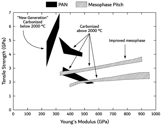
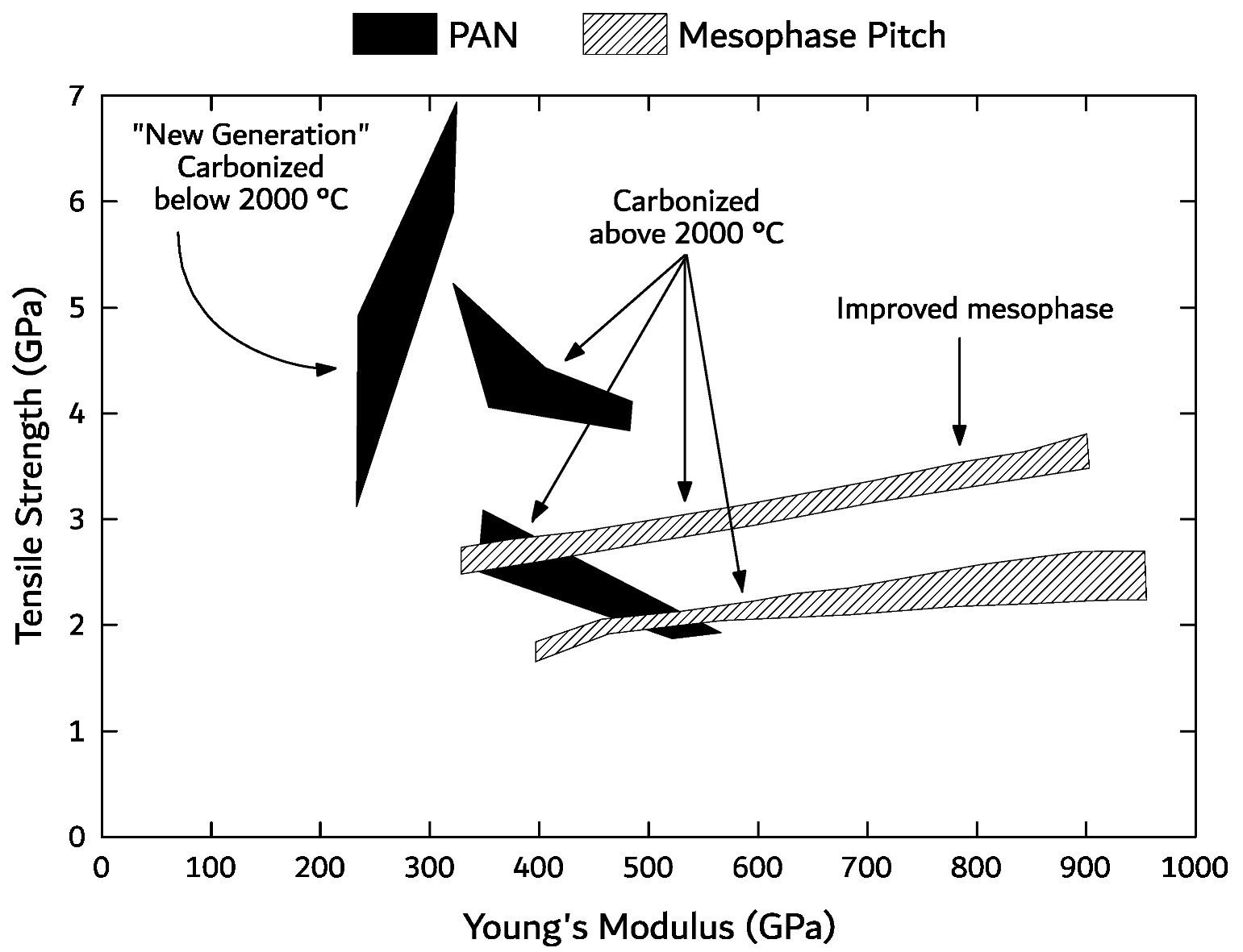


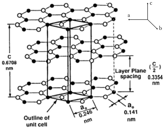
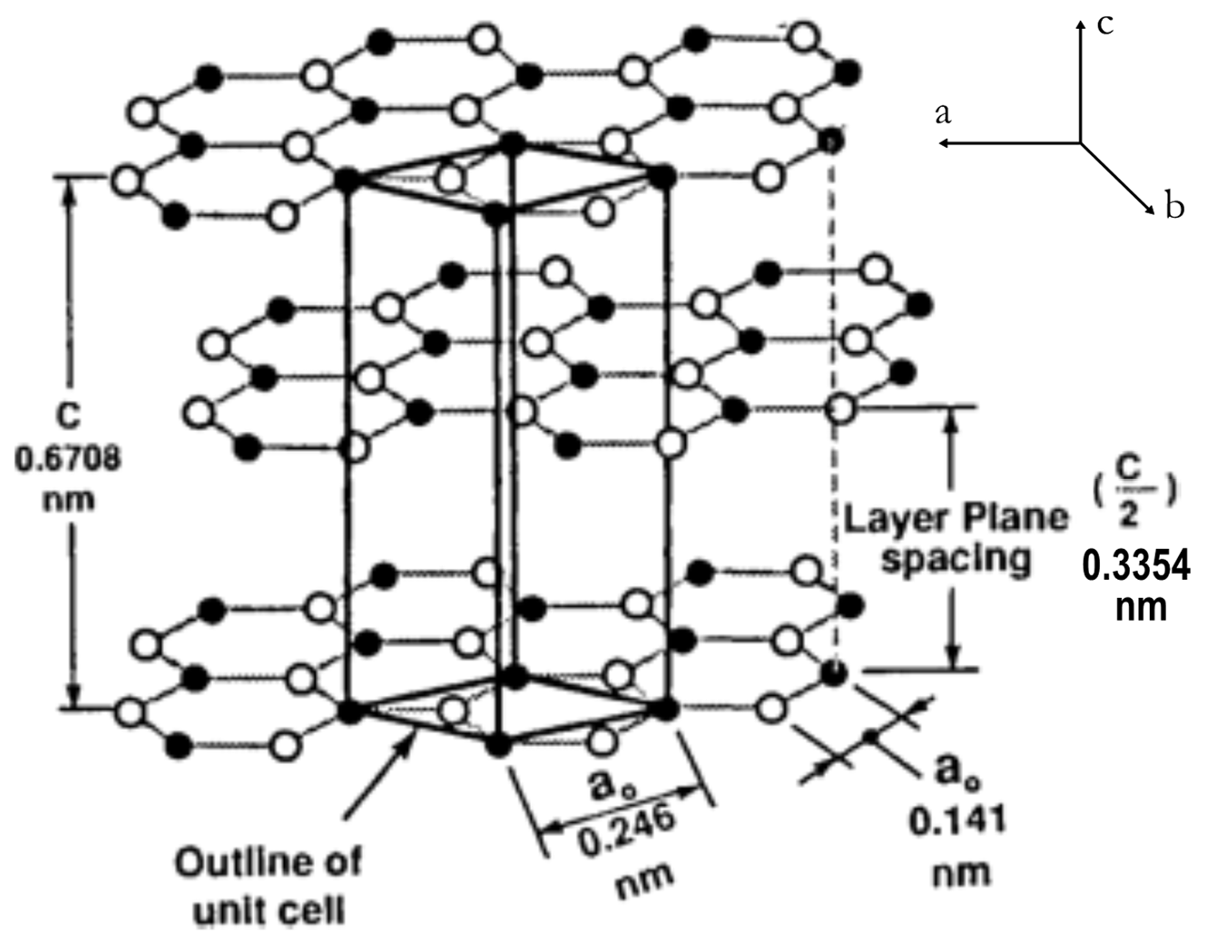
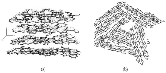
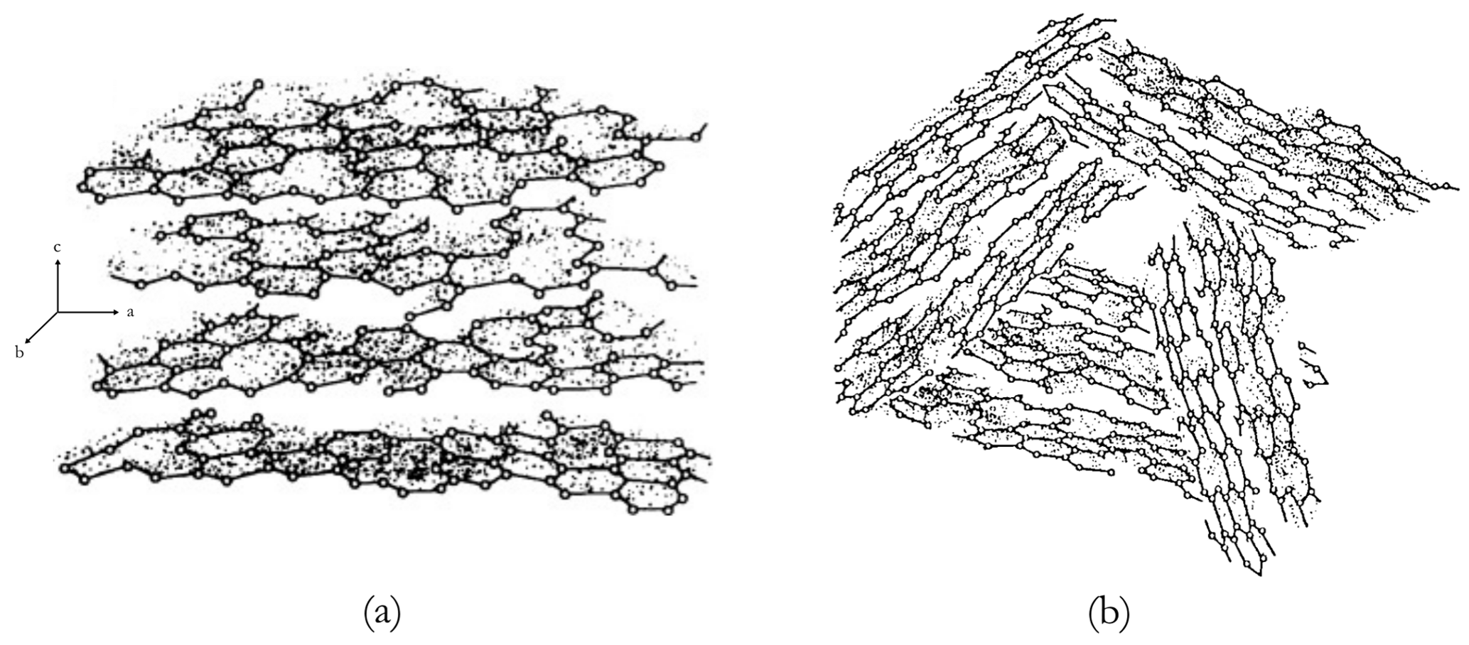
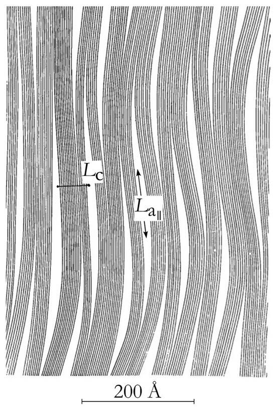
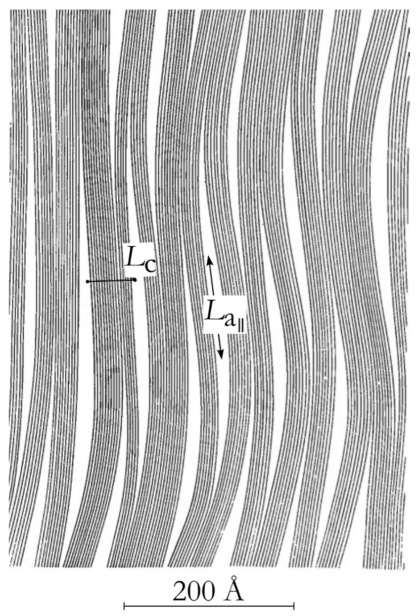
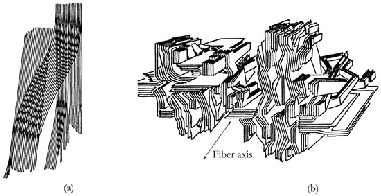
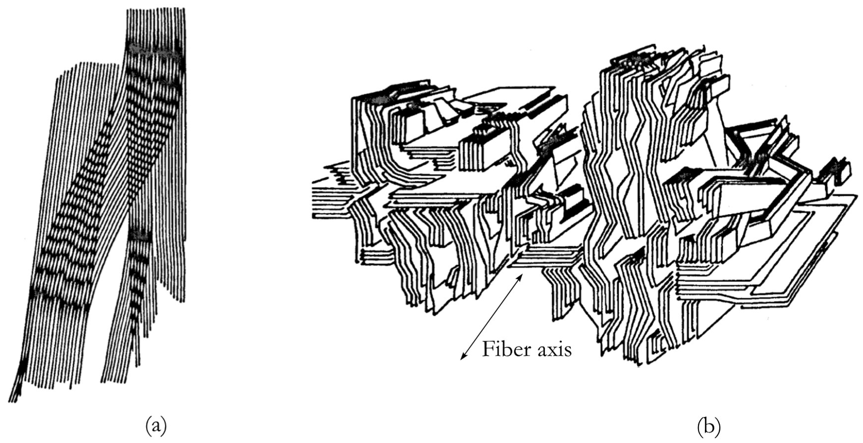
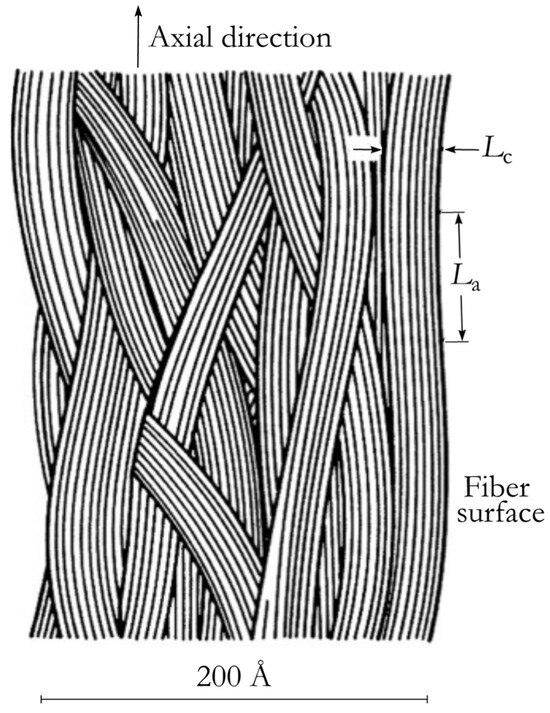
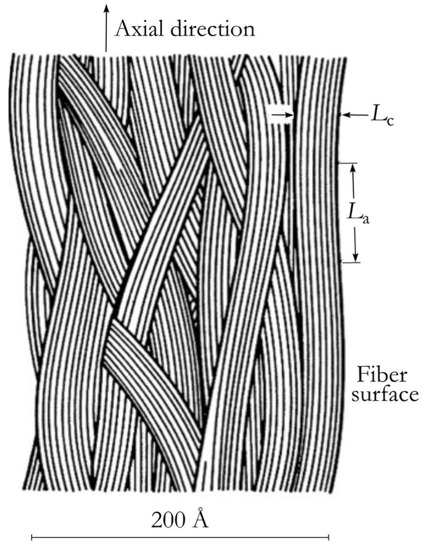
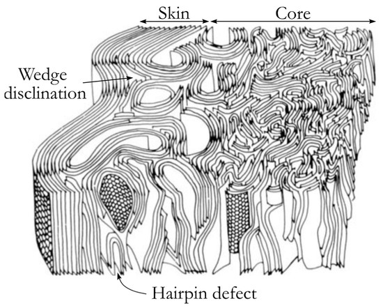
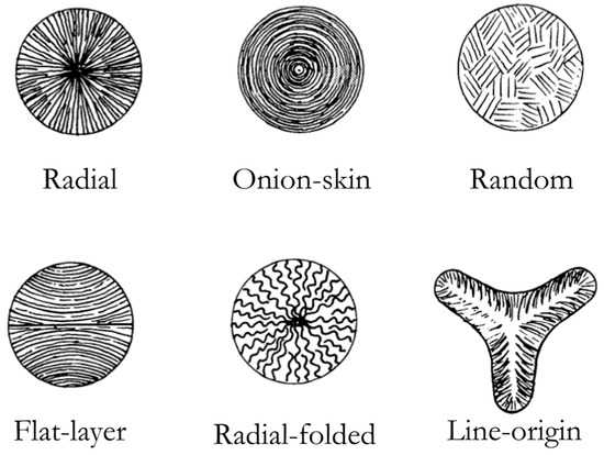

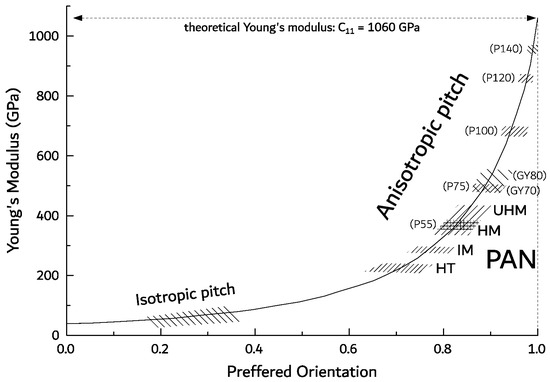
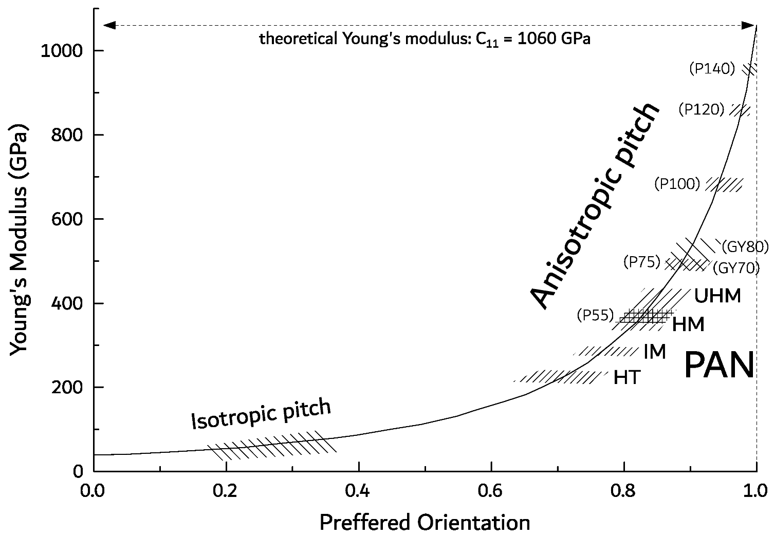
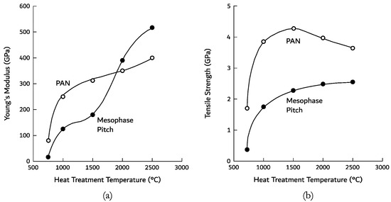
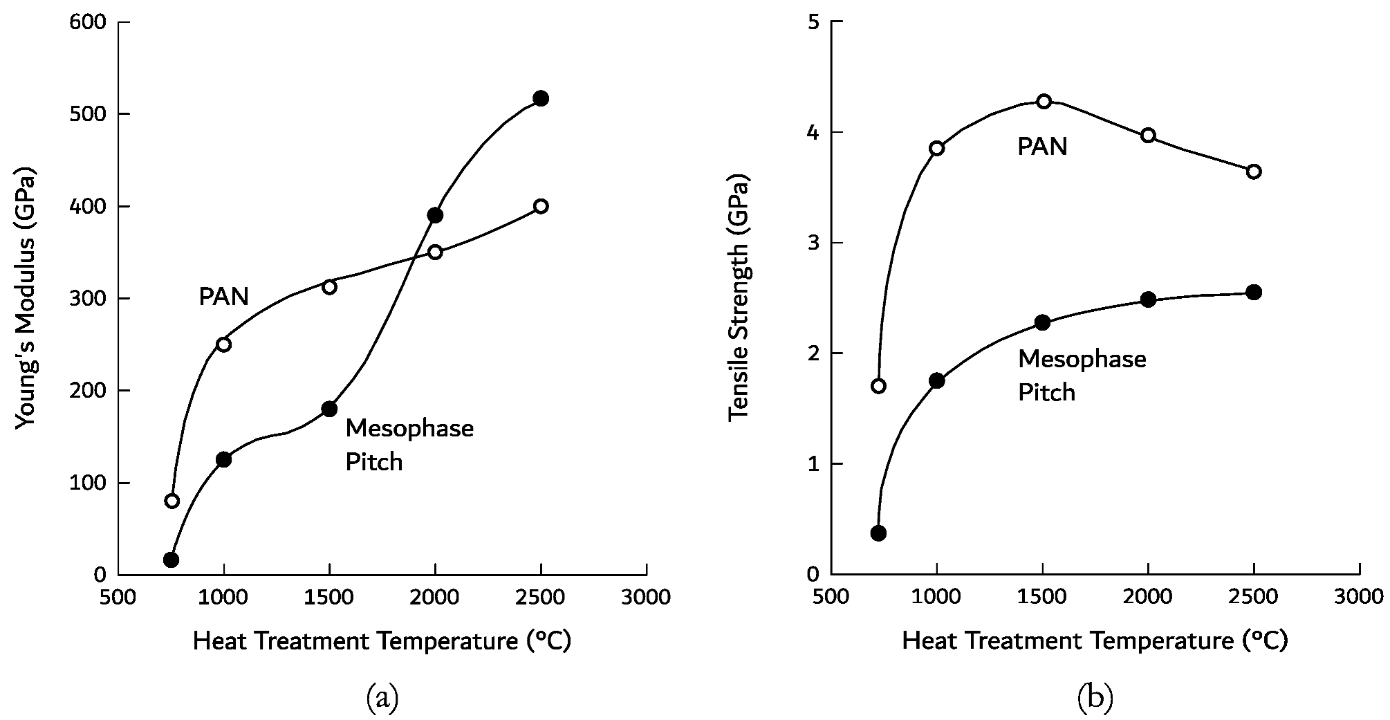
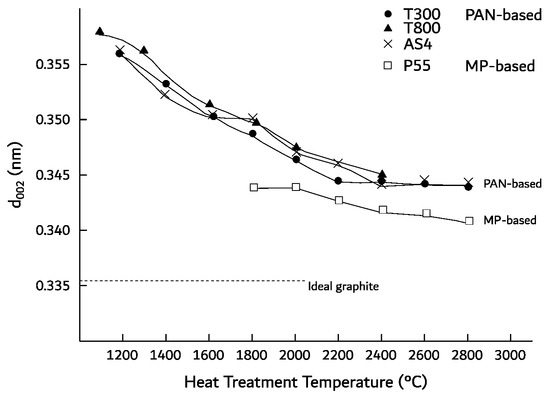
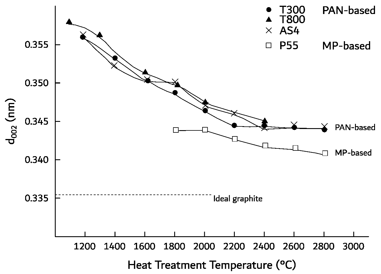
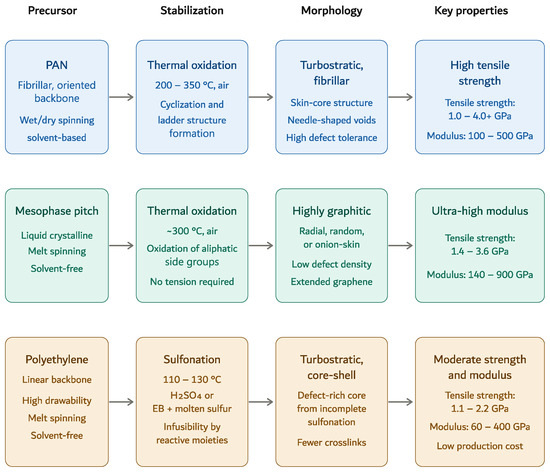
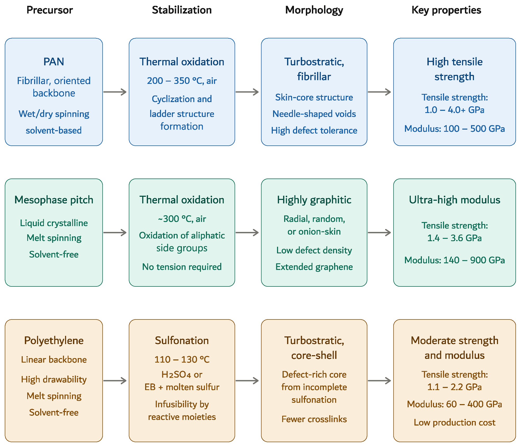
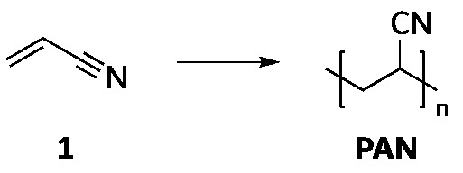
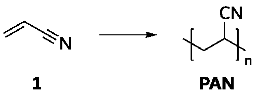
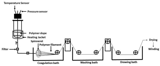
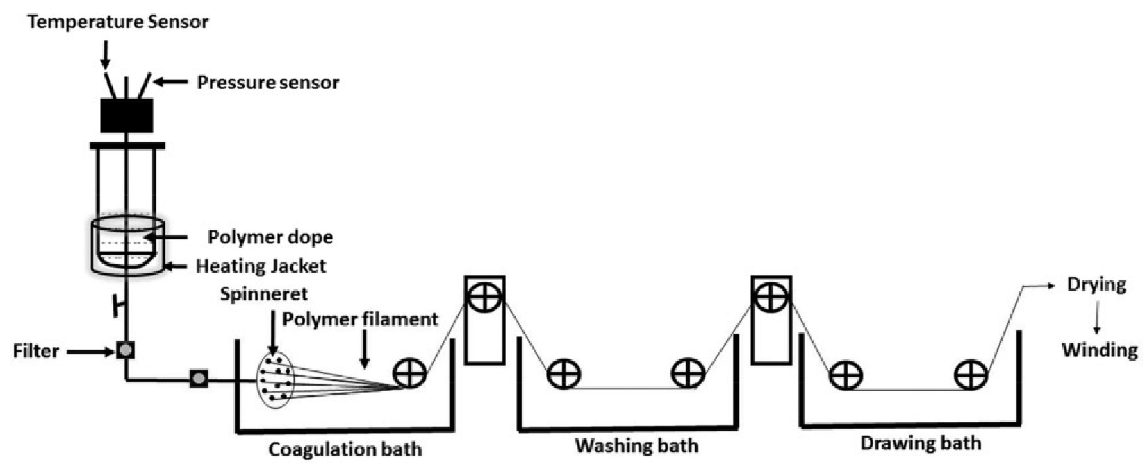
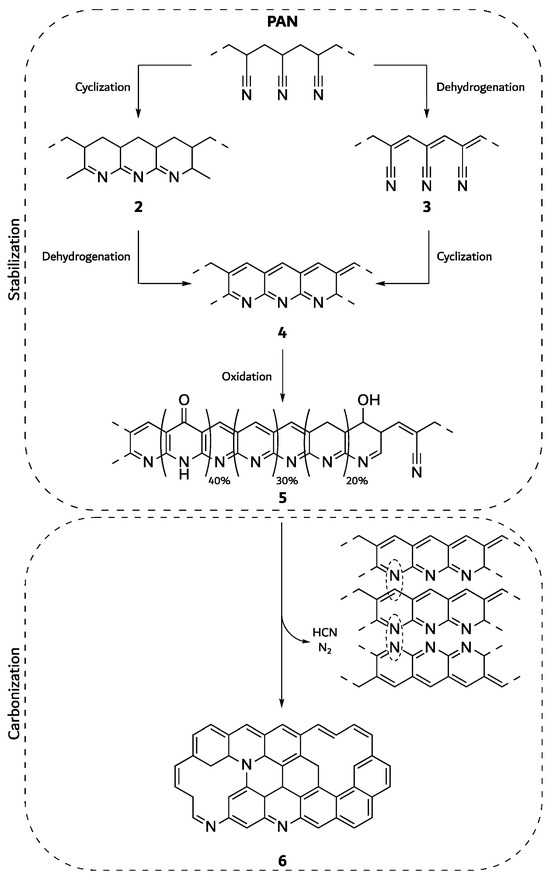
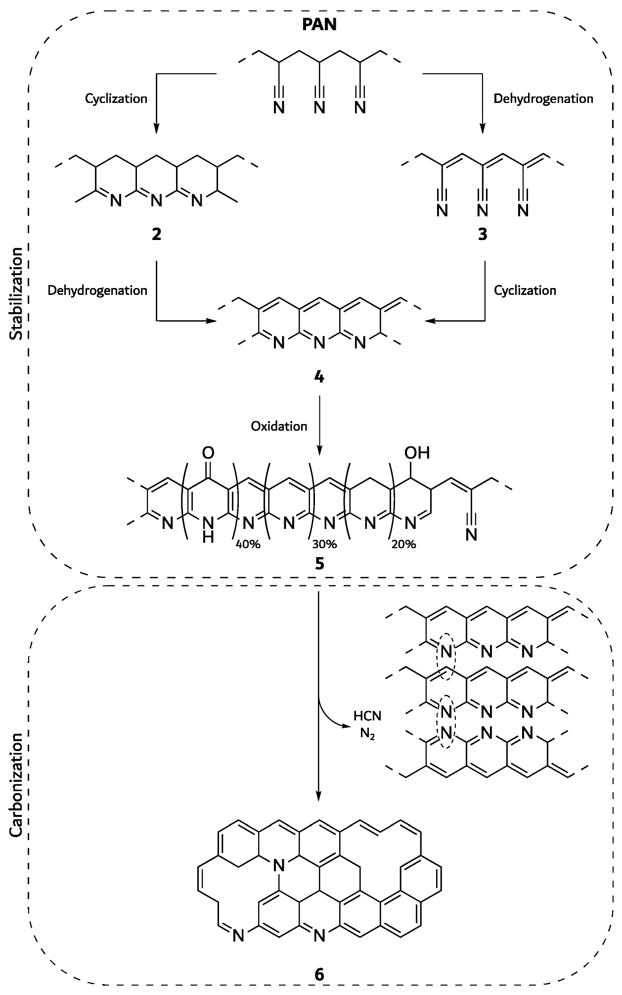
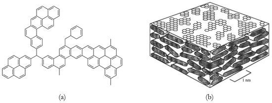
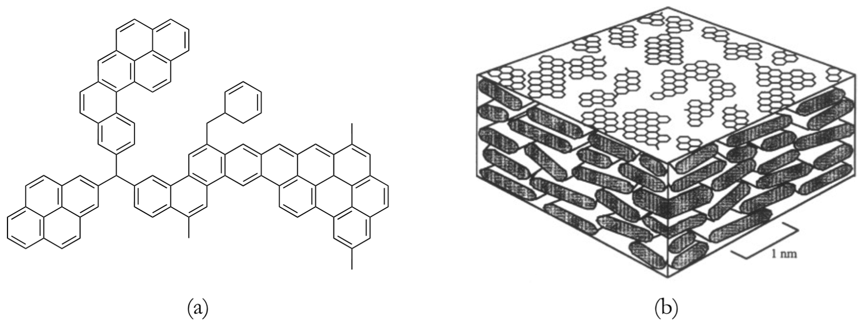
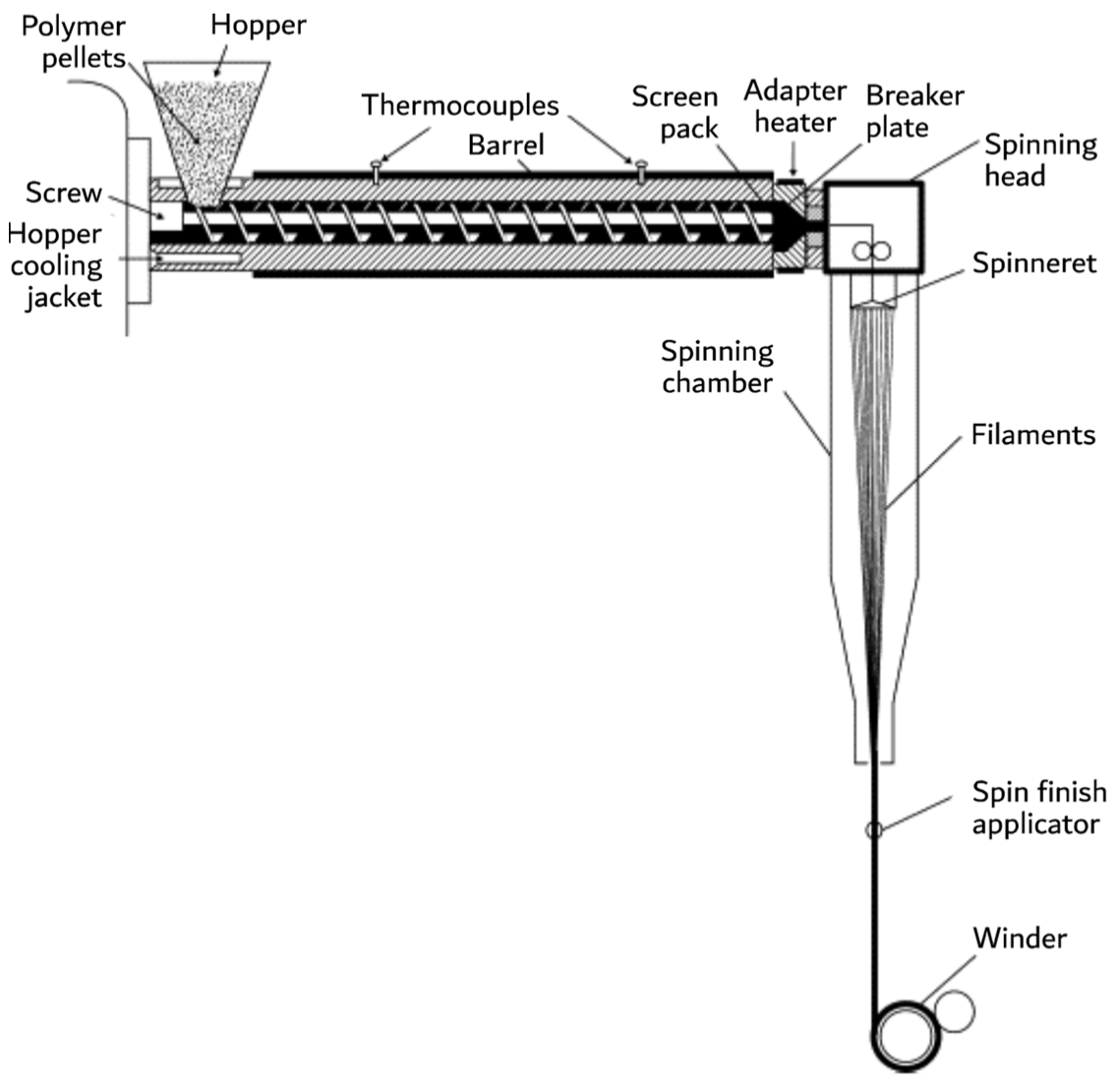
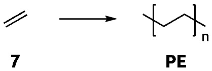
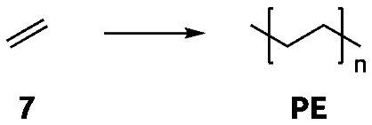
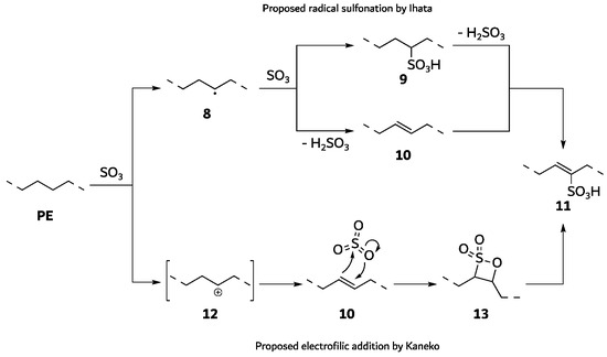
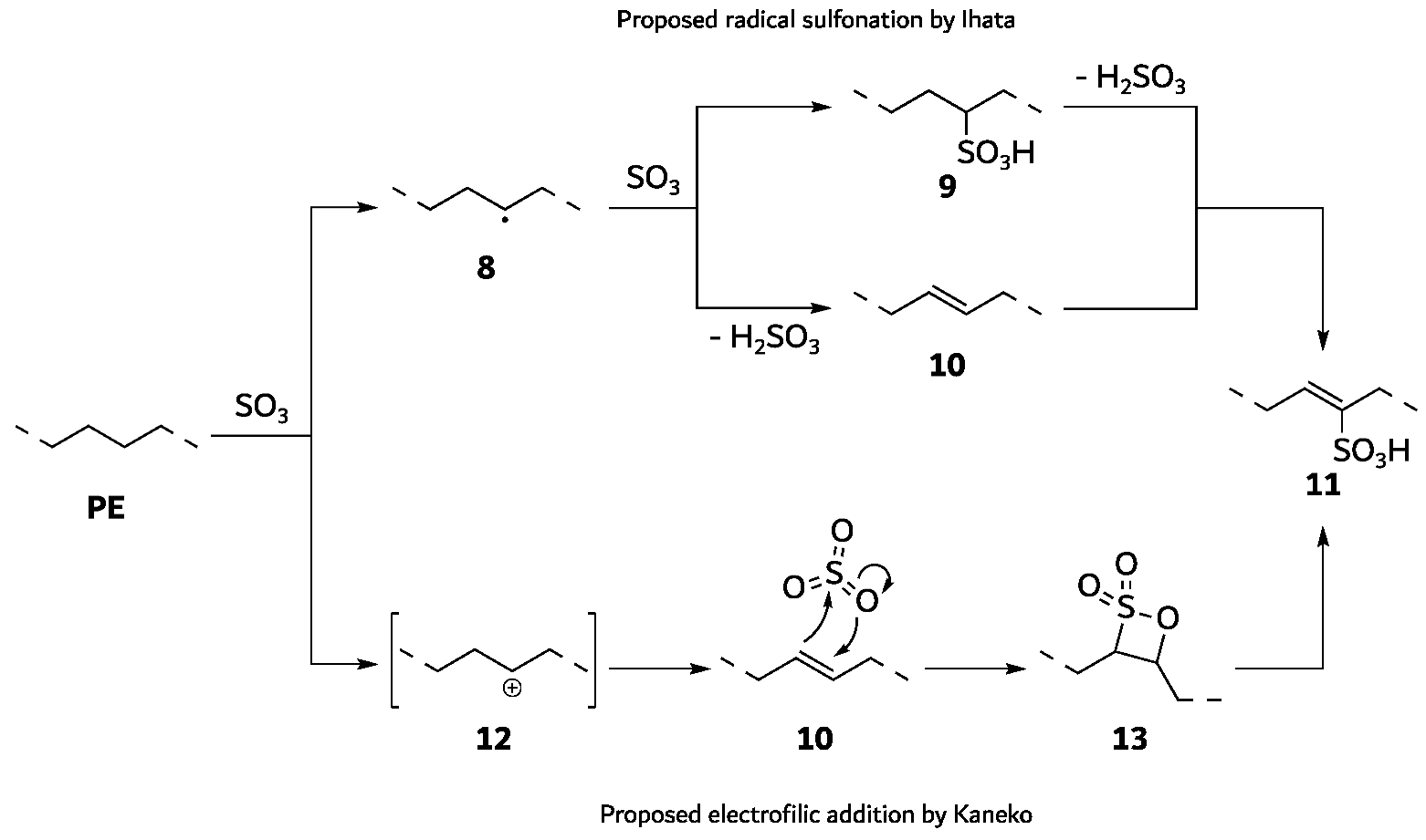
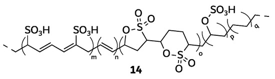
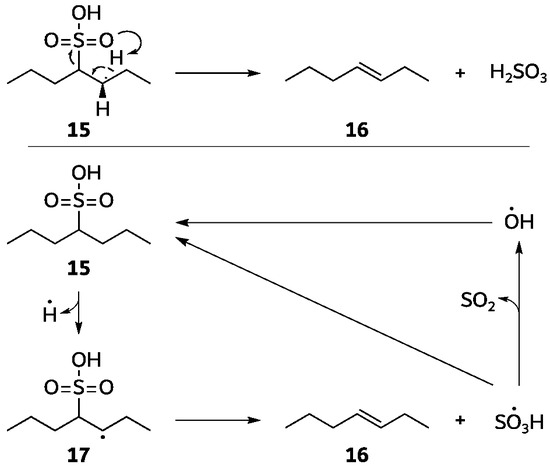
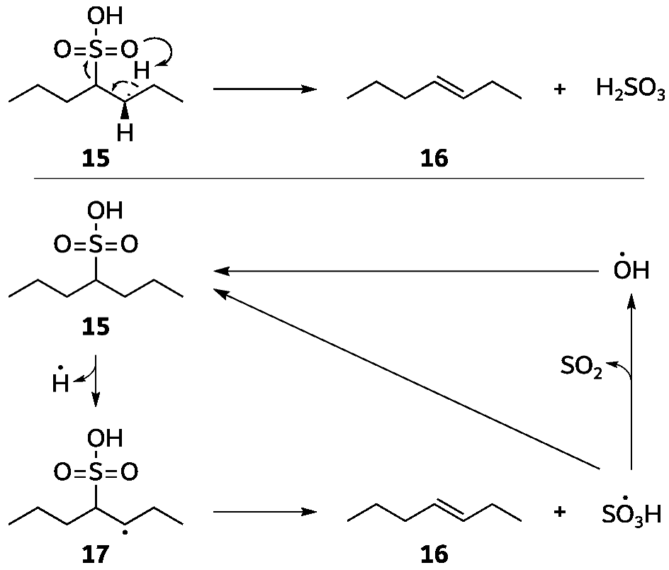
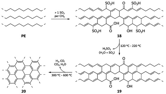
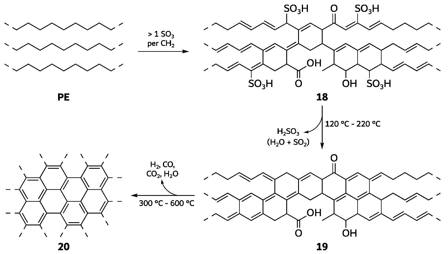
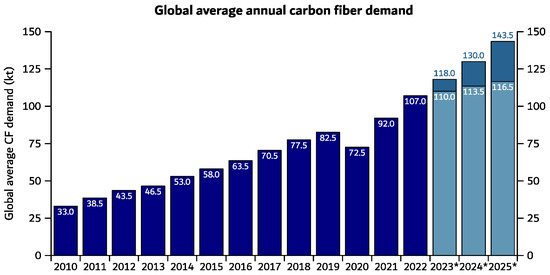
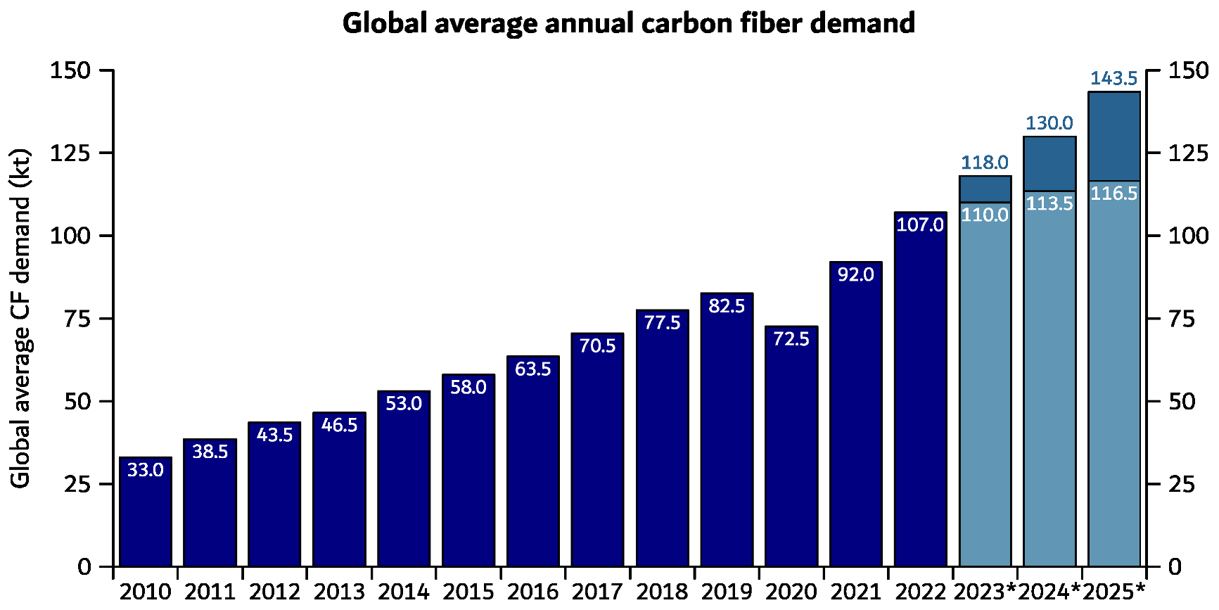
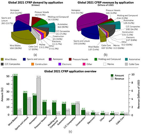
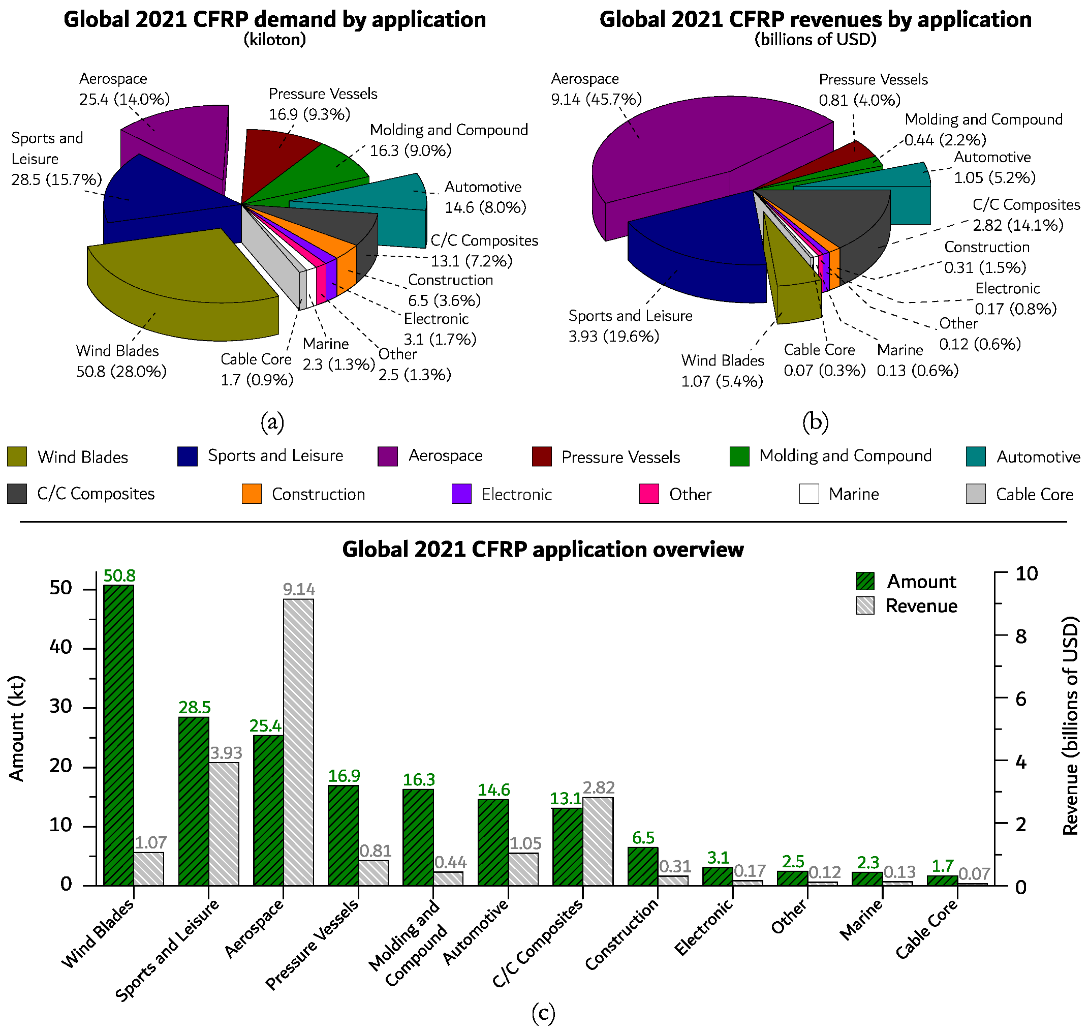

Disclaimer/Publisher’s Note: The statements, opinions and data contained in all publications are solely those of the individual author(s) and contributor(s) and not of MDPI and/or the editor(s). MDPI and/or the editor(s) disclaim responsibility for any injury to people or property resulting from any ideas, methods, instructions or products referred to in the content. |
© 2026 by the authors. Licensee MDPI, Basel, Switzerland. This article is an open access article distributed under the terms and conditions of the Creative Commons Attribution (CC BY) license.