


Abstract
Military confined spaces face poor ventilation and severe airborne hazards (toxic gases/particulates), while conventional air purification systems with separate filtration–adsorption units are bulky and hard to miniaturize. Activated carbon fiber paper (ACFP) is a promising integrated filtration–adsorption material, but existing studies lack systematic comparisons of different ACF precursors and rational balancing of adsorption, filtration, and mechanical properties. Herein, ACFPs were fabricated via wet papermaking technology, using two ACFs (rayon-based, RACF, and phenolic-based, PACF) as the adsorptive component, glass wool as a filtration enhancer, and dual-melting-point polyethylene terephthalate (PET) fibers as a mechanical reinforcer. Dynamic adsorption was evaluated via DMMP (a Sarin simulant). Results showed that PACF had a micropore ratio twice that of RACF. Under the optimal formulation (20% glass wool, 30% PET, and 50% ACF), both types of ACFP showed FE0.3 μm ≥ 90%. PACFP outperformed RACFP in comprehensive performance, showing higher adsorption capacity, tensile strength, and filtration quality factor. Both ACFPs exhibited superior bed utilization efficiency (RACFP: 91.3%; PACFP: 86.0%) to granular activated carbon (AC: 82.7%), confirming better dynamic adsorption kinetics. This work provides a rational optimization strategy for ACFPs, offering a lightweight, integrated material for air purification in military confined spaces.
1. Introduction
Military confined spaces characterized by poor natural ventilation are prone to hazards such as toxic gases, explosive vapors, and oxygen depletion [1]. Consequently, stringent requirements are imposed on air quality and safety within these environments [2,3,4]. Among the contaminants, highly toxic agents, especially sarin, pose severe risks to personnel health [5,6], making rapid removal of harmful gases and particulates to concentrations below safety thresholds crucial. Given the distinct mechanisms of air filtration and gas adsorption, no single technology can effectively eliminate all types of airborne pollutants. Traditional air purification devices typically adopt a dual-unit system combining a particulate filter with a toxic gas adsorber. However, the separation of adsorption and filtration units results in complex, bulky systems, hindering miniaturization and lightweighting [7,8,9]. Thus, developing integrated filtration–adsorption materials to simplify device architecture and enhance efficiency is highly significant. Current research predominantly utilizes “sandwich”-structured activated carbon nonwoven materials (“carbon-loaded cloth”). This composite features a three-layer design: an electret-treated melt-blown nonwoven layer for efficient particulate filtration, and a core layer filled with activated carbon particles (ACs) for gas adsorption. Nevertheless, the high density of AC and its reliance on adhesives for fixation between nonwoven layers lead to uneven distribution, particle shedding, and compromised air permeability [10]. By contrast, activated carbon fiber paper (ACFP) has emerged as a promising candidate for air purification, attributed to its excellent uniformity, thin profile, integrated adsorption–filtration capabilities, superior air permeability, high adsorption efficiency, and light weight [11,12,13].
ACFP preparation methods are mainly categorized into whole-paper activation and fiber blending. The whole-paper activation method involves using a pre-formed paper sheet as the precursor, which is subjected to physical or chemical activation by introducing a mixed activator into a high-temperature inert atmosphere after pretreatment. Active sites are generated through etching, thereby yielding ACFP. However, during high-temperature carbonization and activation, paper sheets are prone to shrinkage, deformation, and even cracking, leading to a deterioration in mechanical strength. Consequently, this method suffers from drawbacks such as high energy consumption, complex processing, and poor mechanical integrity of the final product. Moreover, achieving uniform penetration of the activator throughout the entire paper sheet is challenging, which may result in an inhomogeneous pore structure in the resulting activated carbon fibers, ultimately compromising their adsorption performance [14,15,16]. In contrast, the fiber-blending method involves mixing pre-prepared activated carbon fibers (ACFs) with other fibers at a specific ratio to form a slurry, which is then processed via a wet-laid technique to produce ACFPs. This approach relies on the physical entanglement between ACFs and the additional fibers, enabling the fabrication of ACFPs with tailored properties by adjusting the fiber type and content. The fiber-blending method offers advantages such as a simplified process and lower energy consumption. Furthermore, functional materials can be incorporated during preparation to enhance the overall performance of the ACFP. Compared to the whole-paper activation method, the fiber-blending approach features a straightforward preparation procedure and exhibits significant advantages in terms of energy efficiency, performance controllability, and scalability for practical applications, making it the more widely adopted technique [17,18].
Research has demonstrated that the crystalline structure of the precursor significantly influences the pore characteristics of ACFs [19]. However, existing studies have predominantly focused on characterizing the adsorption performance of a single type of ACF for sarin, with few systematic investigations into the underlying mechanisms by which different precursors affect sarin adsorption behavior [20]. Therefore, rayon-based ACF (RACF) and phenolic-based ACF (PACF) were selected as the adsorptive fiber components in this study, primarily based on their distinct precursor structures and surface chemical properties. RACF possesses a well-developed microporous structure and high specific surface area, which facilitates the physical adsorption of sarin molecules. In contrast, PACF is derived from the carbonization and activation of phenolic resin, offering high carbon yield, tunable pore structure, and excellent mechanical strength, thereby providing enhanced adsorption capacity and rapid adsorption kinetics [21]. By comparing these two typical precursor-derived fibers, this study aims to elucidate the influence of different pore structure characteristics on sarin adsorption mechanisms. Glass wool fibers, characterized by their fine fiber diameter, form a dense three-dimensional network within the paper sheet, and effectively improve filtration efficiency while controlling airflow resistance. Moreover, its chemical inertness ensures that the adsorption function of the ACFs remains uncompromised. Dual-melting-point polyethylene terephthalate (PET) fibers serve as the binding component; the low-melting-point fraction melts and bonds with the fiber skeleton during hot-pressing, significantly enhancing the mechanical strength and structural stability of the filter paper, thereby ensuring its durability in practical applications. Consequently, by blending these three types of raw fibers, an integrated adsorption–filtration ACFP with favorable mechanical properties can be successfully fabricated. However, the low intrinsic strength of ACF and weak interfacial bonding give rise to a trade-off among ACFP’s adsorption performance, filtration efficiency, and mechanical properties [22,23,24,25]. Most existing studies focus on single-precursor ACF, lacking systematic comparisons of different precursor types and clear guidelines for balancing the three key properties.
In this study, rayon-based ACF (RACF) and phenolic-based ACF (PACF) were selected as adsorptive fiber materials, blended with non-adsorptive glass wool and dual-melting-point polyethylene terephthalate (PET) fibers to prepare ACFP [26,27]. Fine-diameter glass wool was incorporated to modulate filtration performance, while dual-melting-point PET fibers were used to enhance mechanical properties. Dimethylmethylphosphonate (DMMP) was employed to simulate the highly toxic nerve agent Sarin [5,25,28,29], to evaluate the dynamic adsorption kinetics of ACFP. By varying the ACF precursor type and fiber-blending ratios, the structure–property relationships among adsorption, filtration, and mechanical performance were systematically investigated. The goal was to prepare ACFP with excellent integrated adsorption–filtration capabilities and satisfactory mechanical strength, laying a foundation for the design of advanced air purification devices for military confined spaces.
2. Materials and Methods
2.1. Materials
Rayon-based activated carbon fiber (RACF) was purchased from Jiangsu Sutong Carbon Fiber Co., Ltd. (Nantong, China). Phenolic-based activated carbon fiber (PACF) was purchased from Kuraray Co., Ltd. (Tokyo, Japan). 475-59 Glass wool was purchased from Chongqing Polycomp International Corp. (Chongqing, China). Dual-melting-point polyethylene terephthalate fiber (PET) was purchased from Toray Industries, Inc., Tokyo, Japan. All materials were used as received without further purification unless otherwise specified.
2.2. Preparation of Filter Papers Based on Different Precursor ACFs
2.2.1. Preparation of RACF-Based Filter Paper (RACFP)
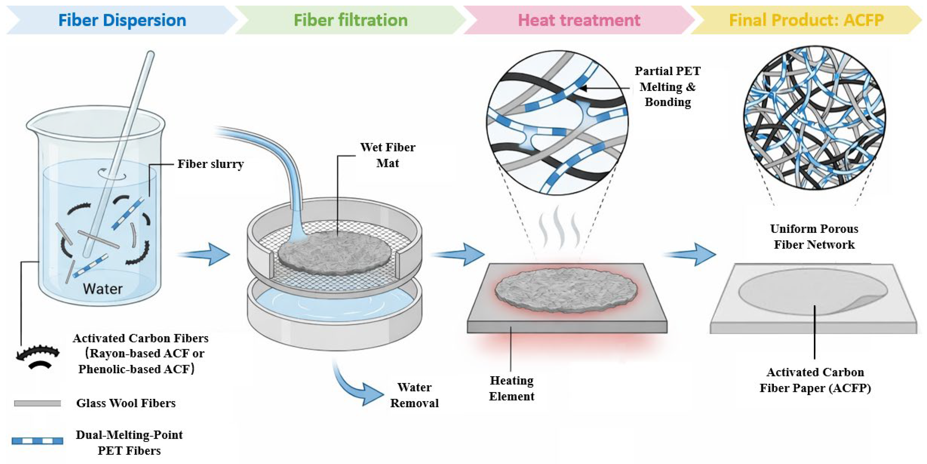
RACFP with a target basis weight of 70 g/m2 was fabricated via wet forming [17]. RACF, dual-melting-point PET fibers, and 475-59 glass wool were dispersed in a specified volume of deionized water and homogenized in a standard fiber disintegrator (IMT-SJ02, Dongguan IMT Precision Instrument Co., Ltd., Dongguan, China) at 20,000 revolutions per minute (rpm). The homogeneous slurry was cast onto a sheet former with an effective area of 314 cm2 (IMT-SJ02, Dongguan, China). After rapid dewatering, a circular wet sheet (diameter = 20 cm) was obtained. The wet sheet was transferred to a plate dryer and cured at 120 °C for 20 min to remove residual moisture (Figure 1).
Figure 1.
Fabrication process of ACFP.
2.2.2. Preparation of PACF-Based Filter Paper (PACFP)
PACFP (basis weight = 70 g/m2) was prepared using the identical wet-forming protocol as RACFP. PACF, dual-melting-point PET fibers, and 475-59 glass wool were processed under the same conditions to ensure consistent fabrication parameters.
2.3. Characterization of ACF and ACFP
2.3.1. Microstructural Characterization
The morphologies of RACF, PACF, RACFP, and PACFP were observed using a field emission scanning electron microscope (FE-SEM, Sigma 360, ZEISS, Tokyo, Japan). Fiber diameters were measured from SEM micrographs using ImageJ software (V 1.54f), with 50 randomly selected fibers analyzed per sample to ensure statistical reliability.
2.3.2. Textural Properties
The specific surface area (SSA) and pore size distribution of all samples were determined using a surface area and porosity analyzer (BELSORP MAX X, Microtrac BEL, Osaka, Japan) via N2 adsorption–desorption at 77 K and CO2 adsorption–desorption at 273 K. The specific surface area was calculated using the Brunner–Emmett–Teller (BET) model for relative pressures (p/p0) ranging from 0.05 to 0.35. The total pore volume of the sample was determined from the nitrogen adsorption at p/p0 = 0.98. Density functional theory (DFT) was applied to analyze pore size distributions.
2.3.3. Macroscopic Property Testing
Sheet thickness was measured using a thickness gauge (HK210D, IMT, Dongguan IMT Precision Instrument Co., Ltd., Dongguan, China) following GB/T 3820-1997 (GB/T 3820-1997; Determination of thickness of textiles and textile products. Standards Press of China: Beijing, China, 1997). (Chinese National Standard for textile thickness determination). Air permeability was tested with an air permeability tester (FX 3300, Textest, Schwerzenbach, Switzerland) complying with GB/T 5453-1997 (GB/T 5453-1997[S]. Textiles—Determination of the permeability of fabrics to air. Standards Press of China: Beijing, China, 1997).
2.4. Adsorption Performance Testing of ACFP
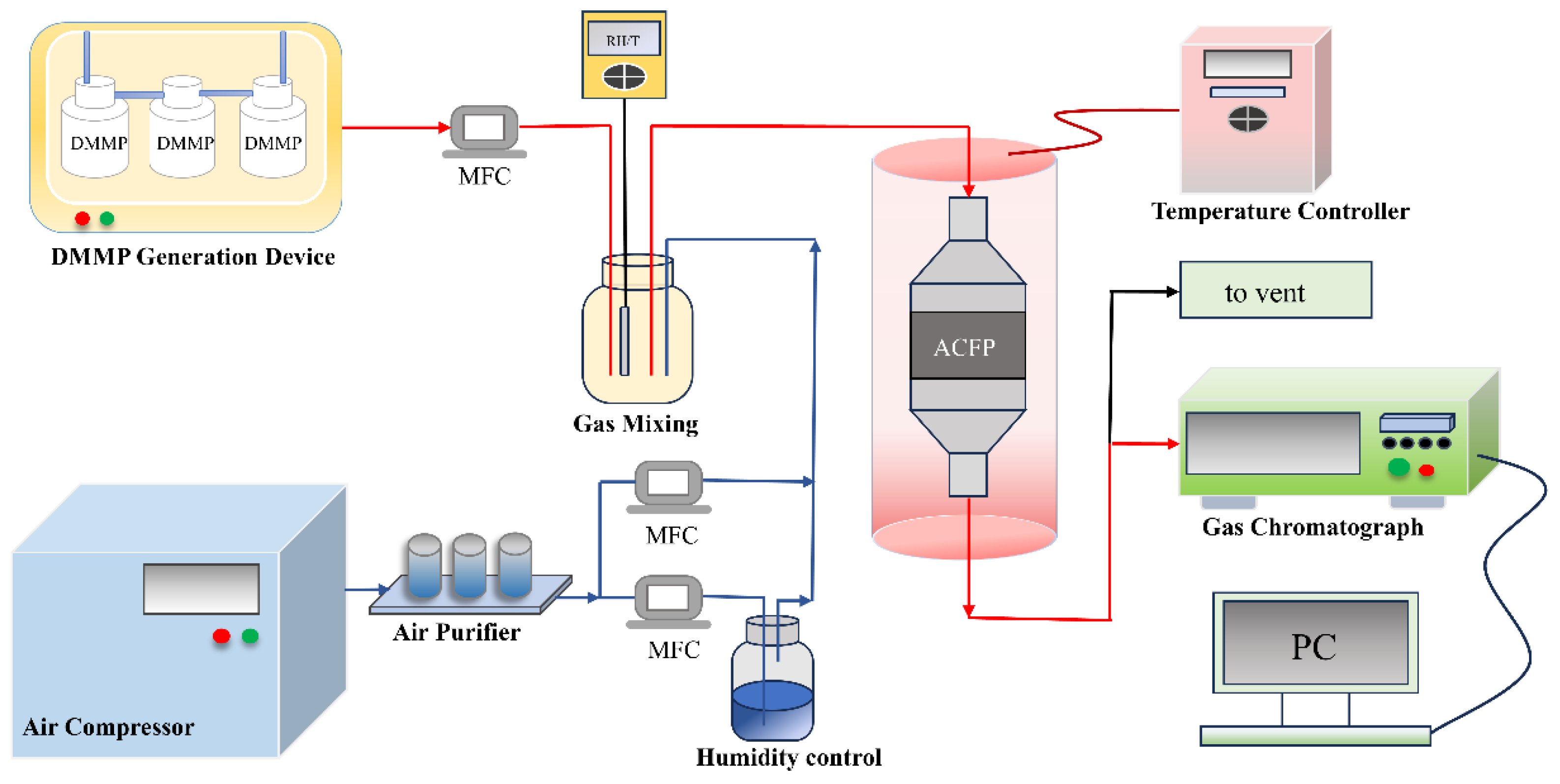
The dynamic adsorption evaluation system for DMMP consists of five integrated modules: gas supply, DMMP generation, gas mixing, reaction, and detection/data acquisition (Figure 2). The gas supply module includes an air compressor (flow rate: 0–5 L/min; relative humidity (RH) < 5%), an air purifier, a humidity control unit (flow rate: 0–5 L/min; RH: 0.5–90%, bubble method), and mass flow controllers (MFCs). The gas stream is split into two paths: one for clean carrier gas and the other for humidity adjustment. The DMMP generation module comprises a DMMP reservoir, a constant-temperature water bath, and an MFC, and the gas mixing module includes a mixing chamber and a temperature/humidity sensor to ensure uniform and stable gas conditions prior to entering the reaction module. The reaction module consists of a temperature controller, a constant-temperature reaction bed (30–80 °C), and a cylindrical sample holder (diameter = 2 cm). The detection and data acquisition module uses a gas chromatograph (GC-FID, 6890, Agilent, Santa Clara, CA, USA) for quantifying high-boiling-point organic pollutant concentrations, with data recorded and analyzed via a computer.
Figure 2.
Schematic diagram of the DMMP dynamic adsorption performance evaluation setup (The arrows in the diagram indicate the direction of gas flow, with blue lines representing the ambient-temperature gas line, red lines representing the insulated gas line, and black lines representing the exhaust gas line).
Breakthrough curves were obtained by monitoring the inlet () and outlet () DMMP concentrations over time and plotting the / ratio against time. Breakthrough time was defined as the time when / = 0.1, and saturation time as when / = 0.98. The saturation adsorption capacity was calculated by integrating the breakthrough curve using Equation (1) [17]:
where is the gas flow rate (L/min), is the mass of ACF in the sample (g), and is the adsorption capacity of VOCs per gram ACFP at time t (mg/g).
The length of unused bed (LUB) corresponds to the mass transfer zone length in the fixed bed, calculated using Equation (2). Bed utilization efficiency (η, %) was derived from LUB via Equation (3) [17]:
where is the bed/sample thickness (mm), is the breakthrough time (min, at / = 0.1), and is the time corresponding to / = 0.5 on the symmetrical breakthrough curve (min).
2.5. Filtration Performance Testing
Filtration efficiency is a key indicator of filter material performance, reflecting the ability to capture particulate matter under specific conditions. It is defined as the ratio of captured particles to the initial particle count in the system, calculable by weight, count, or volume. Among these, counting-based efficiency is widely preferred for its high accuracy and minimal deviation. Filtration efficiency () was calculated using Equation (4) [30].
where and are the upstream and downstream particle number concentrations (particles/cm3), respectively.
Pressure drop is another key parameter for evaluating the filtration performance of filter media. Defined as the pressure difference between the air inlet and outlet of the filter media under specified test conditions, its magnitude directly reflects the energy consumption imposed on the filtration system using the filter material.
Initial filtration efficiency and pressure drop were tested using an automated filter tester (8130, TSI Inc., Santa Clara, CA, USA) in accordance with EN143. The test aerosol consisted of NaCl particles with a mass median diameter of 0.3 μm, at a face velocity of 5.3 cm/s and a flow rate of 32 L/min.
The filter quality factor is used to compare the filtration performances of the filter samples [31]. It is a standard parameter in filtration research. The filter quality factor (QF) can be calculated using Equation (5) [30].
where Q is the quality factor (Pa−1), is the filtration efficiency of the filter sample (%), and is the pressure drop across the filter sample (Pa).
2.6. Mechanical Properties Testing
The tensile strength of the filter paper was determined in accordance with ISO 1924.2:2008 [32] paper and board–determination of tensile strength–constant rate of extension method. ACFP samples were cut into dimensions of 100 mm × 15 mm, tensile strength of the sample was tested using a toilet paper tensile strength tester (IMT, Dongguan, China) at a strain rate of 20 mm/min [33]. All test results are reported as the average of five parallel measurements.
3. Results and Discussion
3.1. Comparison of Different Precursor Activated Carbon Fibers
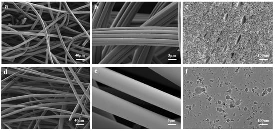
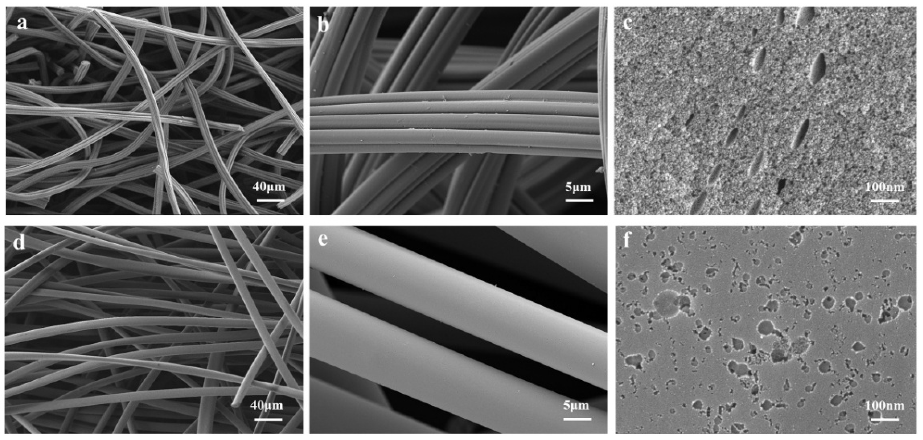
Figure 3 presents the SEM micrographs of the two ACFs: a rayon-based ACF (RACF, Figure 3a–c) and a phenolic-based ACF (PACF, Figure 3d–f). As illustrated in Figure 3a,d, both ACFs exhibit similar fiber entanglement morphologies and uniform diameter distributions, ranging from 10 to 20 nm. Quantitative analysis via ImageJ reveals an average diameter of 11.1 nm for RACF and 12.6 nm for PACF, indicating that PACFs are relatively thicker. This difference can be attributed to the higher activation temperature required for achieving high specific surface areas; pore etching during activation widens the fiber structure, reducing the yield of finer ACFs. Consequently, thicker precursor fibers are more suitable for producing high-specific-surface-area ACFs under elevated activation temperatures [34]. In addition, distinct differences in micromorphology are observed between the two ACFs: RACF displays a filament-cluster-like structure, whereas PACF exhibits a smooth cylindrical morphology. Etched macropores are visible on the surfaces of both fibers; however, RACF features uniformly dispersed narrow slit-like pores, while PACF possesses densely packed, non-uniform elliptical pores, indicating a more compact surface pore structure in PACF.
Figure 3.
SEM images of the two ACFs. (a–c) RACF; (d–f) PACF.
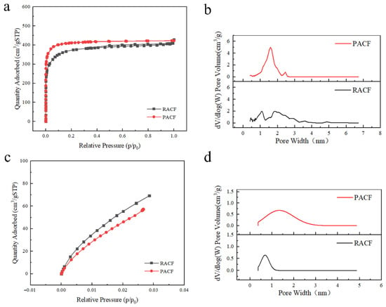
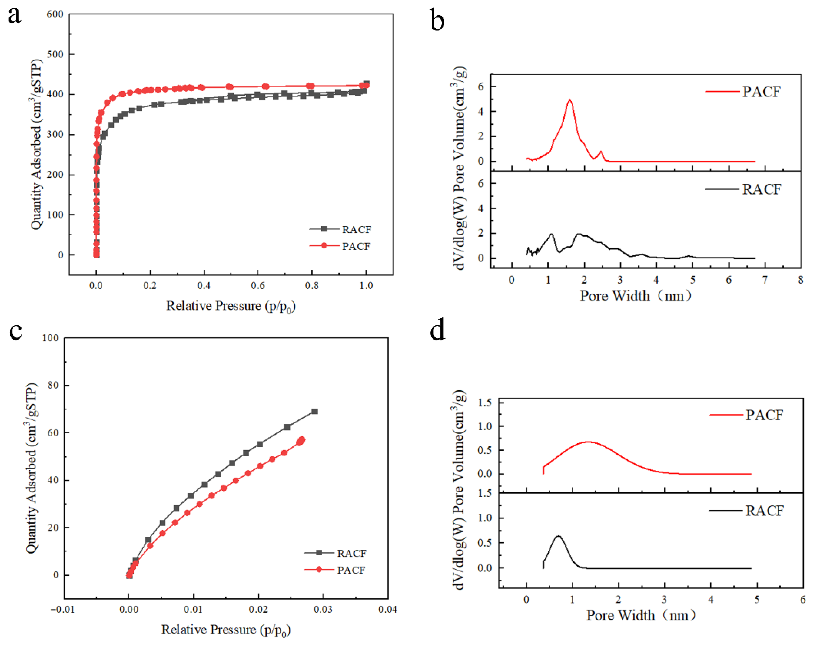
As shown in Figure 4a, both ACFs exhibit Type I isotherms according to IUPAC classification [35], characteristic of microporous materials. The adsorbed volume increases sharply at relative pressures (p/p0) ≈ 0.1, approaching saturation due to the strong adsorption potential within micropores, which drives rapid uptake at low pressures. At p/p0 > 0.1, the adsorption rate slows, attributed to multilayer adsorption effects. Notably, the nitrogen adsorption–desorption isotherm of RACF exhibits a hysteresis loop at p/p0 ≈ 0.5, caused by capillary coalescence, indicating that the surface contains a certain proportion of mesoporous structure. PACF’s adsorption and desorption branches nearly overlap, confirming the absence of a significant mesoporous structure. The minimal hysteresis in both samples further verifies that micropores dominate their pore networks. DFT-derived pore size distributions (Figure 4b,d) further highlight structural differences: RACF shows a bimodal distribution, with pores concentrated above 2 nm and a minor fraction around 1 nm, indicating a relatively abundant mesoporous structure. In contrast, PACF displays a unimodal distribution centered around 1.5 nm, reflecting a higher content of concentrated micropores. Within the micropore range (Figure 4d), PACF’s pores are broadly distributed between 1 and 2 nm, while RACF’s micropores are primarily concentrated in the 0.5–1 nm range.
Figure 4.
Pore structure characterization of the RACF/PACF. (a) N2 adsorption–desorption isotherms (77 K/100 kPa); (b) pore size distribution from N2 (DFT method); (c) CO2 adsorption–desorption isotherms (273 K/100 kPa); and (d) micropore size distribution from CO2 (DFT method).
As summarized in Table 1, both materials exhibit comparable BET surface areas (~1400 m2/g) and total pore volumes (0.65 cm3/g). However, PACF’s micropore area ratio (57%) is twice that of RACF (29%), and its average micropore diameter (1.30 nm) is nearly double that of RACF’s (0.67 nm). These differences are critical for adsorption performance, as pore size strongly influences adsorbate diffusion: pores that are too large or too small relative to the adsorbate’s kinetic diameter impair adsorption efficiency. The optimal adsorption potential and mass transfer efficiency are achieved when the adsorbate’s kinetic diameter is slightly smaller than the adsorbent’s pore diameter. The simulant DMMP (kinetic diameter ~0.7 nm) is primarily adsorbed in micropores of 0.7–2 nm [20]. Therefore, PACF’s higher micropore fraction and larger average micropore size are expected to be more favorable for DMMP adsorption compared to RACF.
Table 1.
Pore structure parameters of the ACFs.
3.2. Structure–Property Relationships Among Adsorption, Filtration, and Mechanical Performance of ACFPs from Different Precursors
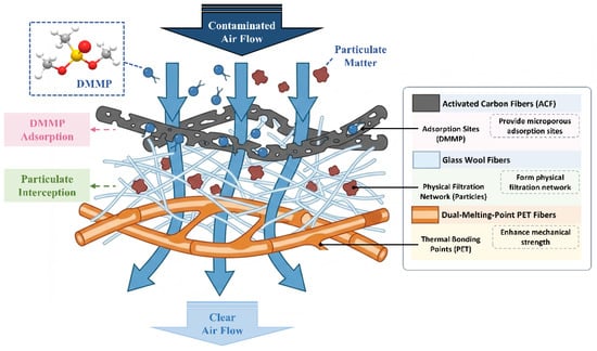
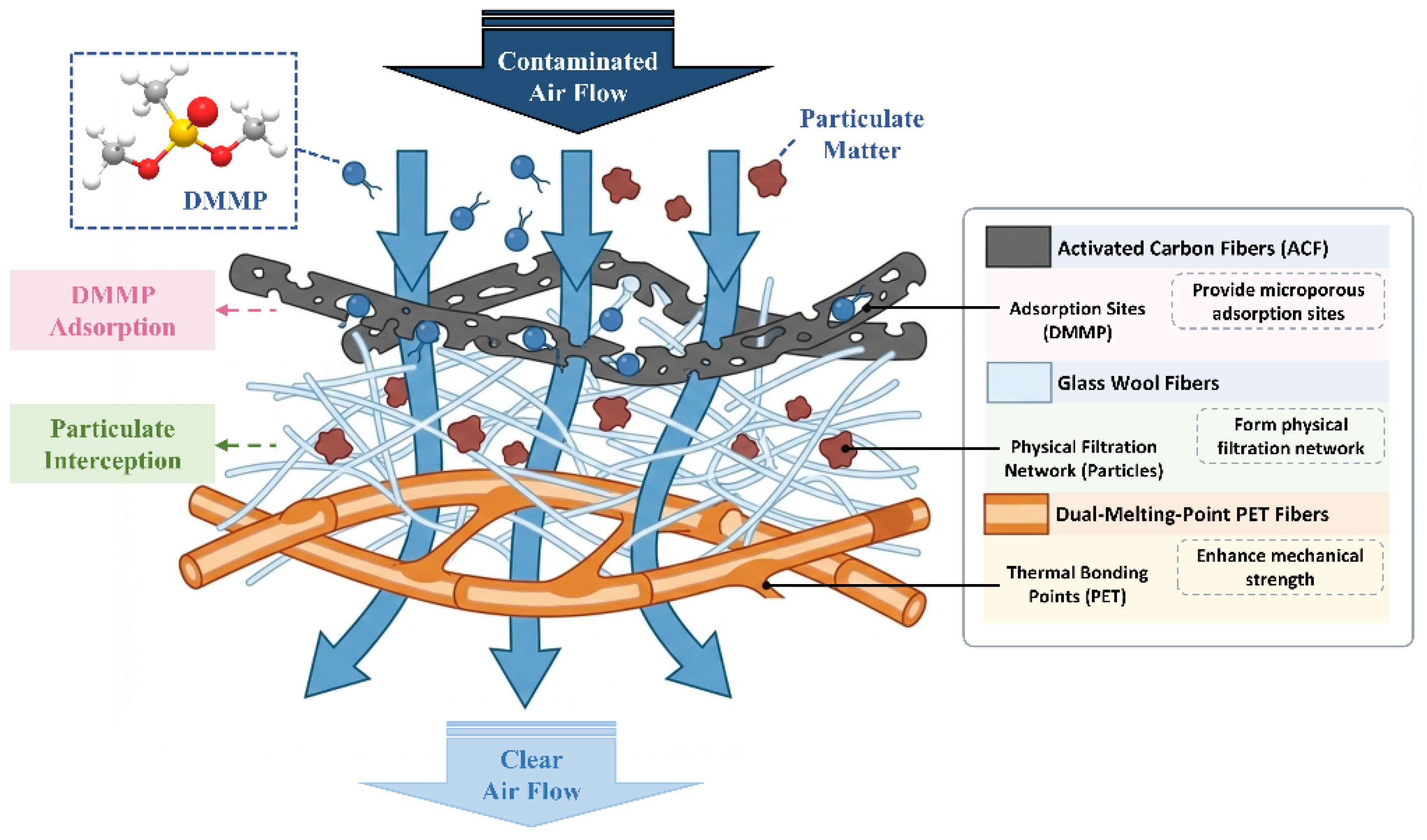
Figure 5 illustrates the adsorption and filtration mechanisms of ACFP. Within the ACFP composite, each component dictates a key property: the ACFs govern adsorption through their high specific surface area and porous structure; the glass wool enhances filtration efficiency via its fine fiber diameter; and the dual-melting-point PET fibers provide mechanical reinforcement by melt-bonding to surrounding fibers, determining tensile strength. Generally, a higher ACF content improves adsorption but compromises filtration and mechanical properties. Therefore, elucidating the trade-offs among these three-performance metrics is essential for designing ACFPs with balanced, superior functionality.
Figure 5.
Adsorption and filtration mechanisms of ACFP.
3.2.1. Adsorption–Filtration Performance Relationship
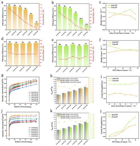
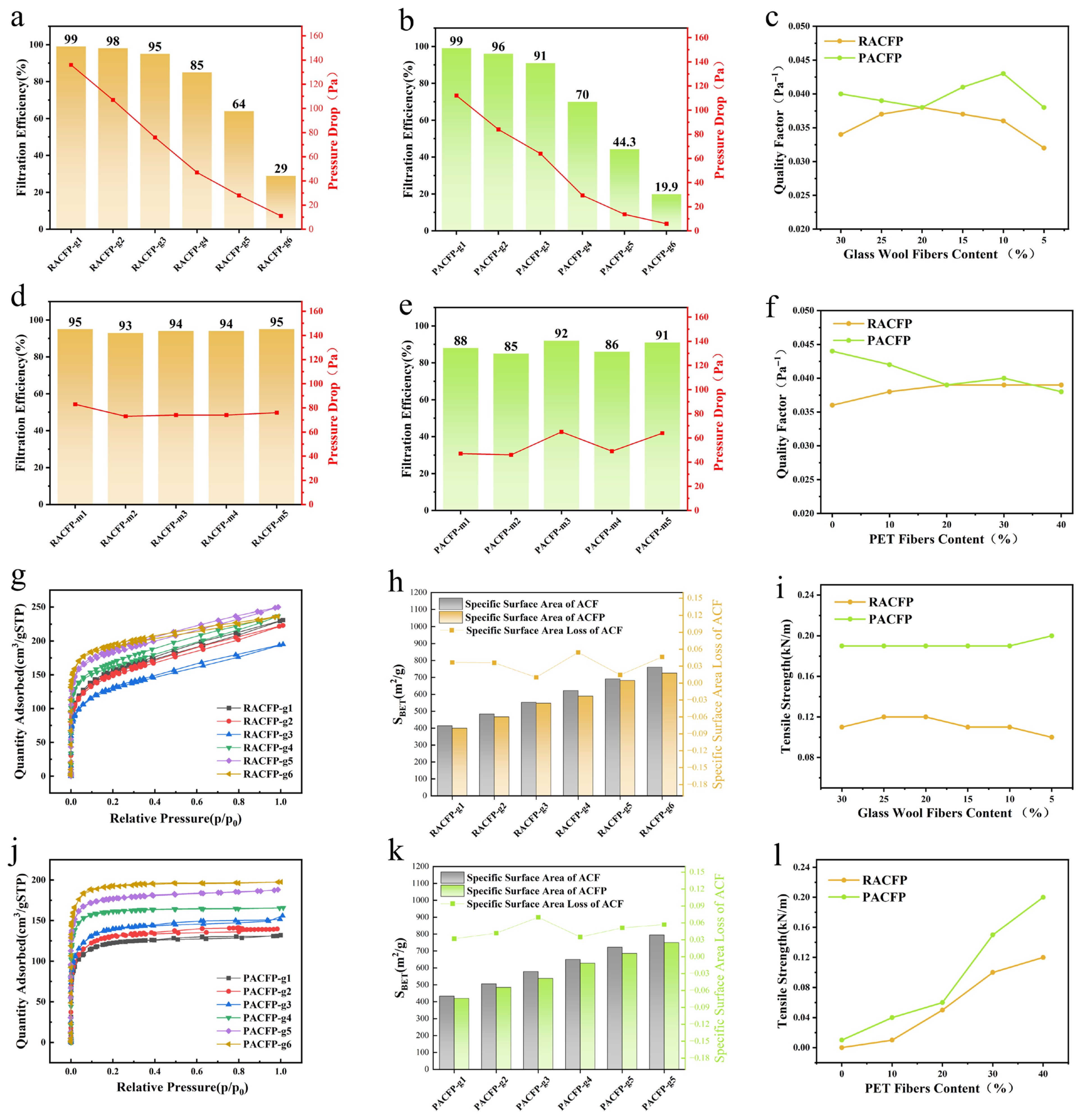
To clarify the adsorption–filtration trade-off, PET fiber content was fixed while glass wool content was varied (Table 2). As shown in Figure 6a,b, filtration efficiency and resistance both increase with higher glass wool content, indicating improved filtration performance. Conversely, Figure 6g,h,j,k confirms that ACFP SSA is positively correlated with ACF content—reducing ACF content (to increase glass wool) decreases SSA, reaffirming ACFs as the primary determinant of adsorption performance.
Table 2.
Fiber formulations for different RACFPs/PACFPs.
Figure 6.
Filtration efficiency and resistance of RACFP-gx (a), PACFP-gx (b), RACF-mx (d), and RACFP-mx (e); quality factor comparison of RACFP-gx and PACFP-gx (c), RACFP-mx and PACFP-gx (f); tensile strength of RACFP-gx and PACFP-gx (i), RACFP-mx and PACFP-mx (l); nitrogen adsorption–desorption isotherms (N2, 77 K, 100 kPa) of RACFP-gx (g), PACFP-gx (j); and loss rate of ACF of RACFP-gx (h) and PACFP-gx (k).
Notably, RACFP reaches or exceeds the H10 filtration grade when glass wool content exceeds 15%, whereas PACFP requires ≥20% glass wool to achieve the same grade. For both ACFPs, the rate of filtration performance improvement slows markedly at glass wool contents ≥20%, with further increases offering only marginal benefits. Thus, 20% glass wool is identified as the optimal proportion to balance filtration efficiency and adsorption capacity, enabling the fabrication of medium-to-high efficiency ACFPs.
3.2.2. Adsorption-Mechanical Performance Relationship
When investigating the adsorption-mechanical balance, glass wool content was fixed, and PET fiber content was adjusted (Table 2). After sheet formation, the SSA of both RACFP and PACFP remained largely unchanged, with a minimal loss rate (~6%). This slight loss is attributed to minor ACF attrition during wet papermaking, indicating that PET fiber melt-bonding barely blocks ACF pores or impairs adsorption performance. Mechanical testing (Figure 6l) shows tensile strength increases with higher PET fiber content. A reduction in PET content from 30% to 20% caused a >50% drop in tensile strength, signifying severe mechanical deterioration. Thus, a minimum of 30% PET fiber is required for optimal mechanical reinforcement, representing the optimal ratio to balance adsorption and mechanical performance.
3.2.3. Filtration-Mechanical Performance Relationship
The effects of the filtration and reinforcing components are independent. Figure 6i,l shows that tensile strength remains stable when the PET content is fixed, and glass wool is varied. Additionally, Figure 6c,d demonstrates that filtration parameters change negligibly when glass wool content is fixed, and PET is adjusted. This confirms that glass wool and PET fibers regulate filtration and mechanical properties, respectively, without mutual interference.
3.2.4. Performance Comparison Between RACFP and PACFP
Under identical formulations, PACFP exhibits higher SSA and pore volume than RACFP—consistent with the superior textural properties of its precursor PACF relative to RACF (Section 3.1). With 40% PET content, PACFP’s tensile strength is approximately twice that of RACFP (Figure 6i), and this mechanical advantage persists across all PET content variations (Figure 6l). This difference stems from precursor-inherent characteristics: phenolic resin’s high cross-linking density forms a denser, more uniform carbon skeleton during carbonization, reducing internal fiber defects and enhancing PACF strength/rigidity. In contrast, RACF develops more pores and structural defects during carbonization (pyrolysis and dehydration stages), diminishing its mechanical strength [36]. Furthermore, due to the finer fiber diameter of RACF compared to PACF, RACFP exhibits higher filtration efficiency. However, filtration efficiency and pressure drop are a pair of conflicting parameters; evaluating the filtration performance of a material using either alone is one-sided. Thus, the quality factor of the filter media has been proposed as a balanced indicator to assess filtration performance. The higher the quality factor, the better the filtration performance. As shown in Figure 6c,f, the quality factor of RACFP is lower than PACFP, indicating that PACFP demonstrates superior overall filtration performance. This discrepancy may be attributed to the inherent brittleness of activated carbon fibers. During the refining process, the shear forces applied by the fiber disintegrator can compromise the integrity of ACF. RACF is more susceptible to fiber breakage, length reduction, and even pulverization during refining, whereas PACF, with its higher mechanical strength, is less affected [37]. In summary, PACFP outperforms RACFP in integrated adsorption, filtration, and mechanical properties.
To integrate the structure–property relationships outlined above, the optimal formulation for a medium- to high-efficiency activated carbon fiber paper (ACFP) was determined to be 50% ACF, 30% dual-melting-point PET fiber, and 20% glass wool. This composition balances high adsorption capacity, effective filtration, and sufficient mechanical strength. Based on this formulation, RACFP and PACFP samples were fabricated via wet papermaking, and their key properties are summarized in Table 3.
Table 3.
Basic properties of PACFP and RACFP.
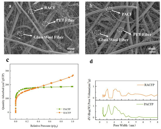
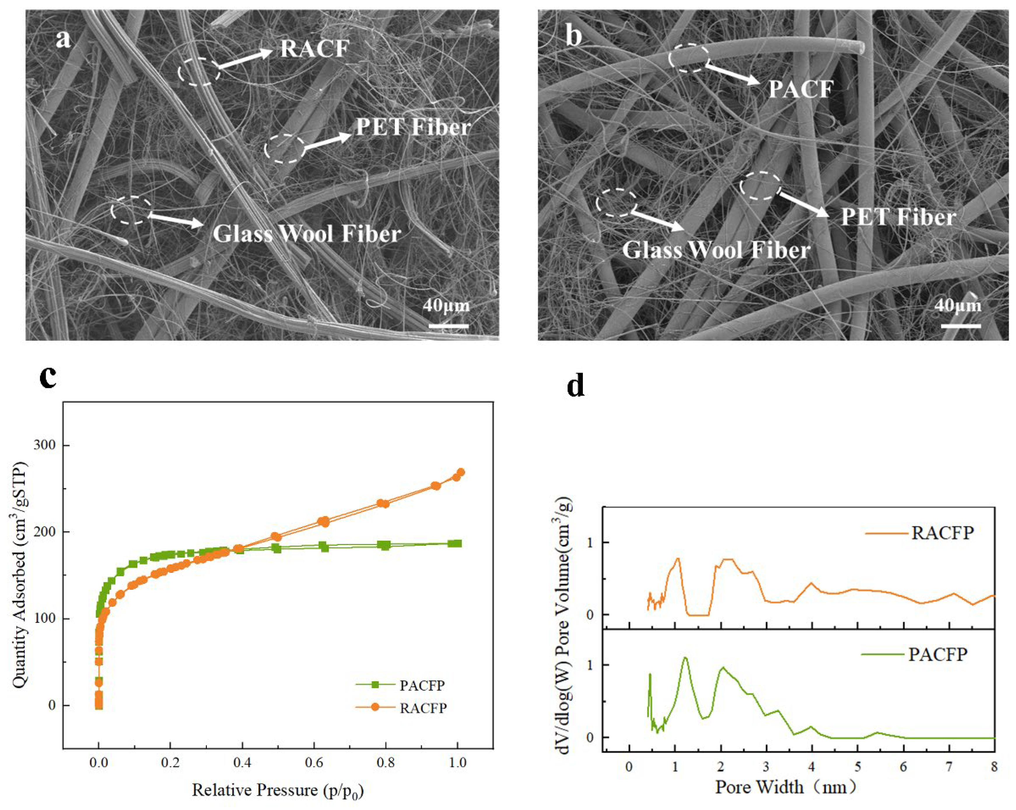
Figure 7c shows the nitrogen adsorption–desorption isotherms of RACFP and PACFP. At low relative pressures (p/p0 < 0.05), both RACFP and PACFP exhibit a sharp initial rise, indicating a strong affinity of the paper surfaces for adsorbate molecules. In this region, adsorption occurs primarily via monolayer coverage on high-energy adsorption sites. Within the p/p0 range of 0.05–0.2, RACFP tends to enter the plateau region earlier than PACFP, suggesting that it possesses fewer high-energy adsorption sites compared to PACFP. When p/p0 exceeds 0.2, the adsorption isotherm of RACFP continues to rise slightly even after reaching the plateau. This gradual increase may be attributed to slow multilayer adsorption at higher relative pressures, or to pore-filling effects associated with the relatively abundant mesoporous structure in the sample, corresponding to adsorption on lower-energy sites. In contrast, the isotherm of PACFP follows a typical Type I behavior according to the IUPAC classification, indicating that the surface is dominated by high-energy binding sites and exhibits characteristic microporous features.
Figure 7.
Basic property characterization of RACFP/PACFP. (a) SEM of RACFP; (b) SEM of PACFP; (c) N2 adsorption–desorption isotherms (77 K/100 kPa); and (d) pore size distribution from N2 (DFT method).
Figure 7d presents the pore size distribution profiles derived from the nitrogen adsorption–desorption isotherms of RACFP and PACFP. Compared to its precursor RACF, the pore size distribution of RACFP remains largely unchanged, still exhibiting a bimodal distribution. A portion of the pores is concentrated around 1 nm, while the majority are distributed above 2.1 nm, with an increased presence of macropores larger than 5 nm. In contrast, the pore size distribution of PACFP changes significantly compared to its precursor PACF, shifting from a unimodal to a bimodal distribution, with peaks centered around 1.2 nm and 2.0 nm. Additionally, mesopores in the 2–3 nm range become more prominent. Despite these changes, the proportion of micropores in PACFP remains substantially higher than that in RACFP.
3.3. Adsorption Kinetics of DMMP on ACFP Beds from Different Precursors
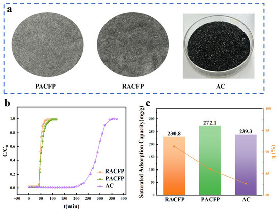
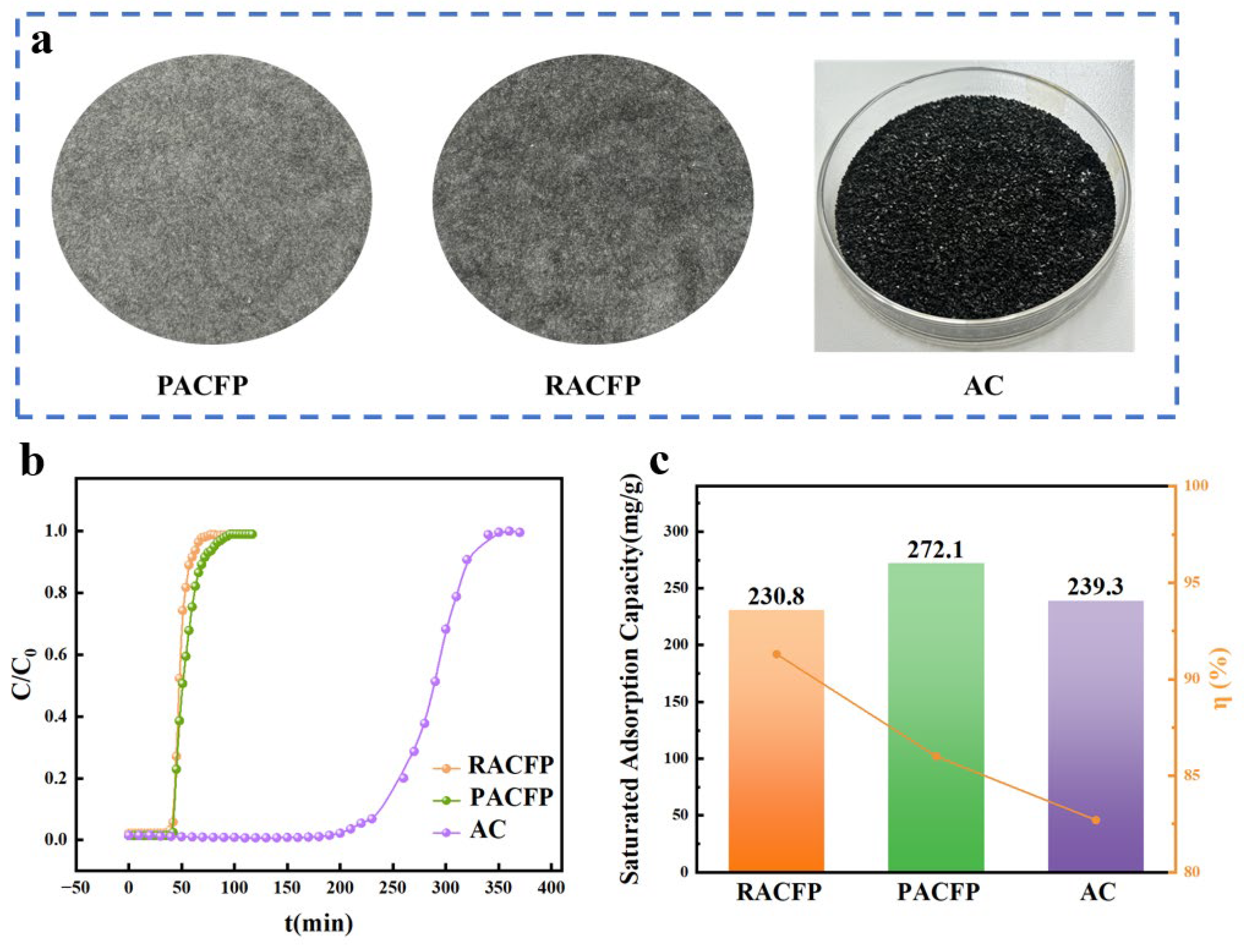
Dynamic adsorption breakthrough curves of DMMP were measured for RACFP, PACFP, and granular activated carbon (AC, sourced from carbon-loaded cloth) under controlled conditions: initial DMMP concentration of 530 ppm, superficial velocity of 0.5 L·min−1·cm−2, and room temperature (Figure 8). Key kinetic parameters, including breakthrough time, saturation time, saturated adsorption capacity, length of unused bed (LUB), and bed utilization efficiency (η), were derived from the breakthrough curves and summarized in Table 4.
Figure 8.
Dynamic adsorption behaviour of DMMP on two types of ACFP and ACs. (a) Schematic diagrams of the two types of ACFP and AC. (b) DMMP adsorption breakthrough curves for the two ACFPs and commercial AC. (c) Comparison of the saturated adsorption capacity and bed utilisation of the two types of ACFP and AC.
Table 4.
Dynamic adsorption performance of DMMP on RACFP, PACFP, and AC beds.
As illustrated in Figure 8 and Table 4, RACFP and PACFP exhibited comparable breakthrough times but distinct saturation behaviors: PACFP required a significantly longer time to reach adsorption saturation than RACFP. In contrast, AC displayed much extended breakthrough time and saturation time. This discrepancy is not attributed to intrinsic superiority in adsorption kinetics of AC, but rather to its higher packing density (which mitigates gas dispersion) and substantially larger adsorbent mass (~four-fold that of ACFPs) under the same bed thickness.
A notable difference in breakthrough curve profiles was observed between the two ACFPs: PACFP showed a gradual ascending trend, whereas RACFP exhibited a steeper breakthrough curve. This variation is directly linked to their pore structure disparities, as established in Section 3.1 and Section 3.2. PACFP features a narrow pore size distribution dominated by micropores, while RACFP possesses a broader distribution with a higher mesopore fraction. Mesopores in RACFP act as rapid mass transfer channels, accelerating DMMP diffusion to internal adsorption sites and thus resulting in a steeper breakthrough profile.
The saturated adsorption capacity of the three adsorbents followed the order: PACFP (272.1 mg/g) > AC (239.3 mg/g) > RACFP (230.8 mg/g). PACFP’s superior adsorption capacity stems from its well-developed microporous structure—characterized by higher micropore volume and proportion (Section 3.1)—which provides abundant accessible adsorption sites for DMMP (kinetic diameter ~0.7 nm). In contrast, RACFP’s lower qsat is attributed to its limited micropore volume, which restricts adsorbate accommodation. For AC, its mesopore-dominated structure offers fewer high-affinity adsorption sites for DMMP, leading to a moderate saturated adsorption capacity between the two ACFPs.
Bed utilization efficiency (η), a critical indicator of adsorbent utilization before breakthrough, followed the reverse order: RACFP (91.3%) > PACFP (86.0%) > AC (82.7%). Both ACFPs outperformed AC in kinetic efficiency, which is closely associated with their structural and precursor-specific properties:
RACF’s inherent flexibility facilitates the formation of a uniform paper structure during wet forming, minimizing mass transfer resistance within the ACFP bed. This uniformity enables rapid and homogeneous diffusion of DMMP to adsorption sites, resulting in a steeper breakthrough curve and higher η.
PACF exhibits higher rigidity (no pre-oxidation required during preparation), leading to a less uniform PACFP structure that increases mass transfer resistance [38]. Additionally, PACF’s dense pore structures may hinder full utilization of internal pores during dynamic adsorption [39], further reducing η.
Compared with the two ACFPs, AC possesses a relatively smaller external specific surface area, with most of its adsorption sites located within complex internal pore channels. This structure significantly restricts the diffusion of DMMP molecules. Additionally, channeling may occur in the packed AC bed, where the fluid follows the path of least resistance, resulting in incomplete utilization of some activated carbon particles within the bed [40].
4. Conclusions
In this study, two types of activated carbon fiber papers—RACFP and PACFP—were prepared via a wet papermaking process using RACF and PACF (derived from different precursors) as the adsorbent fibers, blended with non-adsorptive glass wool and dual-melting-point PET fibers. Fine-diameter glass wool was incorporated to regulate the filtration performance of the paper, while dual-melting-point PET fibers were used to tune its mechanical properties. By varying the type of precursor ACF and the fiber-blending ratios, the structure–performance relationships among adsorption, filtration, and mechanical properties were systematically investigated to develop an integrated adsorption–filtration ACFP with satisfactory mechanical strength. The developed ACFPs achieved FE0.3 μm ≥ 90%, with PACFP outperforming RACFP in comprehensive performance. Additionally, both ACFPs exhibited superior bed utilization efficiency to granular AC, confirming better dynamic adsorption kinetics.
In military confined spaces, where space is limited, air purification requirements such as rapid response to chemical threats and equipment lightweighting are particularly stringent. The optimized ACFP prepared in this study meets these key operational demands. First, the high saturation adsorption capacity of PACFP for DMMP (272.1 mg/g) and its well-developed microporous structure indicate strong potential for effectively removing nerve agent simulants under realistic conditions. Second, compared to conventional activated carbon particle beds (82.7%), the superior bed utilization of RACFP (91.3%) and PACFP (86.0%) implies that equivalent protection can be achieved using thinner adsorbent layers, thereby reducing the weight and space occupied by the filtration unit. Third, the integrated filtration–adsorption functionality of ACFP offers significant advantages in lightweighting and miniaturization for air purification systems. Furthermore, the enhanced mechanical strength imparted by PET fibers ensures structural integrity under vibration and shock loads typical in military operations, preventing adsorbent shedding and performance degradation. Collectively, the developed ACFPs, particularly PACFP, hold great promise for application in air purification systems for military confined spaces, where miniaturization, lightweight design, and integrated pollutant removal are critical requirements.
Author Contributions
Y.F. conceived the idea, carried out the experiment, and wrote the manuscript; J.Z., Z.L., L.W. and M.T. supervised the project. All authors have read and agreed to the published version of the manuscript.
Funding
This research was funded by Guangdong Basic and Applied Basic Research Foundation grant number 2024B1515040016.
Data Availability Statement
The original contributions presented in this study are included in the article. Further inquiries can be directed to the corresponding authors.
Conflicts of Interest
The authors declare no conflicts of interest.
Abbreviations
The following abbreviations are used in this manuscript:
| ACF | Activated Carbon Fiber |
| ACFP | Activated Carbon Fiber Paper |
| RACFP | Rayon-Based Activated Carbon Fiber Paper |
| PACFP | Phenolic-Based Activated Carbon Fiber Paper |
| AC | Activated Carbon |
References
- Botti, L.; Duraccio, V.; Gnoni, M.G.; Mora, C. An Integrated Holistic Approach to Health and Safety in Confined Spaces. J. Loss Prev. Process Ind. 2018, 55, 25–35. [Google Scholar] [CrossRef] [Scilit]
- Liu, Y.; Zhao, Y.; Luo, H.; Liu, F.; Wu, Y. Construction of EGFR Peptide Gefitinib/Quantum Dots Long Circulating Polymeric Liposomes for Treatment and Detection of Nasopharyngeal Carcinoma. Biochem. Biophys. Res. Commun. 2017, 490, 141–146. [Google Scholar] [CrossRef] [Scilit]
- Gutberlet, J.; Baeder, A.M.; Pontuschka, N.N.; Felipone, S.M.N.; Dos Santos, T.L.F. Participatory Research Revealing the Work and Occupational Health Hazards of Cooperative Recyclers in Brazil. Int. J. Environ. Res. Public Health 2013, 10, 4607–4627. [Google Scholar] [CrossRef] [Scilit]
- Selman, J.; Spickett, J.; Jansz, J.; Mullins, B. Confined Space Rescue: A Proposed Procedure to Reduce the Risks. Saf. Sci. 2019, 113, 78–90. [Google Scholar] [CrossRef] [Scilit]
- Talmage, S.; Watson, A.; Hauschild, V.; Munro, N.; King, J. Chemical Warfare Agent Degradation and Decontamination. Curr. Org. Chem. 2007, 11, 285–298. [Google Scholar] [CrossRef] [Scilit]
- Kak, V. Infections in Confined Spaces: Cruise Ships, Military Barracks, and College Dormitories. Infect. Dis. Clin. N. Am. 2007, 21, 773–784. [Google Scholar] [CrossRef] [Scilit]
- Kang, Y.; Low, Z.-X.; Zou, D.; Zhong, Z.; Xing, W. Multifunctional Nanofibrous Membranes for Integrated Air Purification. Adv. Fiber Mater. 2024, 6, 1306–1342. [Google Scholar] [CrossRef] [Scilit]
- Kim, Y.; Lee, G.D.; Doh, S.J.; Im, J.N. Wet-laid Nonwoven of Activated Carbon Fiber for Gas Adsorption Layer in Face Masks. Fibers Polym. 2023, 24, 2711–2723. [Google Scholar] [CrossRef] [Scilit]
- Wang, H.; Zu, D.; Jiang, X.; Xu, Y.; Cui, Z.; Du, P.; Cheng, Z.; Li, Z.; Li, L.; Yang, C.; et al. Bifunctional Activated Carbon Ultrathin Fibers: Combining the Removal of VOCs and PM in One Material. Adv. Fiber Mater. 2023, 5, 1934–1948. [Google Scholar] [CrossRef] [Scilit]
- Balanay, J.A.G.; Crawford, S.A.; Lungu, C.T. Comparison of Toluene Adsorption among Granular Activated Carbon and Different Types of Activated Carbon Fibers (ACFs). J. Occup. Environ. Hyg. 2011, 8, 573–579. [Google Scholar] [CrossRef] [Scilit]
- Son, H.K.; Sivakumar, S.; Rood, M.J.; Kim, B.J. Electrothermal Adsorption and Desorption of Volatile Organic Compounds on Activated Carbon Fiber Cloth. J. Hazard. Mater. 2016, 301, 27–34. [Google Scholar] [CrossRef] [Scilit] [PubMed]
- Rochereau, A.; Marc, B.; Laurence, L.C.; Mauret, E.; Albert, S.; Pierre, L.C. Combined Air Treatment: Effect of Composition of Fibrous Filters on Toluene Adsorption and Particle Filtration Efficiency. Chem. Eng. Res. Des. 2008, 86, 577–584. [Google Scholar] [CrossRef] [Scilit]
- Balanay, J.A.G.; Bartolucci, A.A.; Lungu, C.T. Adsorption Characteristics of Activated Carbon Fibers (ACFs) for Toluene: Application in Respiratory Protection. J. Occup. Environ. Hyg. 2014, 11, 133–143. [Google Scholar] [CrossRef] [Scilit] [PubMed]
- Liu, T.; Li, X.; Xu, C.; Zhang, H. Activated Carbon Fiber Paper Based Electrodes with High Electrocatalytic Activity for Vanadium Flow Batteries with Improved Power Density. ACS Appl. Mater. Interfaces 2017, 9, 4626–4633. [Google Scholar] [CrossRef] [Scilit]
- Li, H.; Sun, G.; Meng, L.; Hu, J. Changes in Properties and Mechanism of Poly(p-Phenylene Terephthalamide) Activated Carbon Paper Prepared by Different Activation Methods. J. Porous Mater. 2024, 31, 1589–1600. [Google Scholar] [CrossRef] [Scilit]
- Chen, J.; Xie, J.; Jia, C.Q.; Song, C.; Hu, J.; Li, H. Economical Preparation of High-Performance Activated Carbon Fiber Papers as Self-Supporting Supercapacitor Electrodes. Chem. Eng. J. 2022, 450, 137938. [Google Scholar] [CrossRef] [Scilit]
- Zhang, X.; Liang, Y.; You, T.; Tian, L.; Xu, G.; Yang, C.; Xiao, J.; Tang, M. The Influence of Activated Carbon Fiber Paper Structure on Adsorption Performance of Cyclohexane. Sep. Purif. Technol. 2024, 348, 127740. [Google Scholar] [CrossRef] [Scilit]
- Liu, W.; Adanur, S. Desulfurization Properties of Modified Activated Carbon Fibers and Activated Carbon Fiber Paper. J. Ind. Text. 2015, 44, 513–525. [Google Scholar] [CrossRef] [Scilit]
- Kim, J.-H.; An, K.-H.; Lee, H.-M.; Kim, B.-J. Effect of Pore Characteristics on DMMP Adsorption of Activated Carbon Fibers from Various Precursors. J. Ind. Eng. Chem. 2024, 143, 655–662. [Google Scholar] [CrossRef] [Scilit]
- Chae, H.M.; Shin, H.; Lee, K.B. Pore Size Tuning of Activated Carbon Fiber through Chemical Drilling and Widening for Adsorption of Chemical Warfare Agent Simulant. J. Ind. Eng. Chem. 2026, 155, 663–671. [Google Scholar] [CrossRef] [Scilit]
- Zhao, Z.; Wu, W.; Li, W.; Wang, X.; Li, G.; Cheng, J.; Zhang, Z.; Hao, Z. Thermosetting Phenolic Resin-Derived Activated Carbon Fibers for Volatile Organic Compound Adsorption: Electrospinning, Preoxidation, and Carbonization. ACS EST Eng. 2024, 4, 1635–1643. [Google Scholar] [CrossRef] [Scilit]
- Yang, R.; Liu, J.; Li, S. Preparation and Characterization of In-Site Regenerated TiO-ACFs Photocatalyst. Int. J. Miner. Metall. Mater. 2011, 18, 357–363. [Google Scholar] [CrossRef] [Scilit]
- Daghistani, F. Conceptual Design and Performance Evaluation of an Air-Cushion Floating Purifier (ACFP) for Improving Air Quality in Semi-Confined Spaces. Energy Build. 2023, 300, 113672. [Google Scholar] [CrossRef] [Scilit]
- Kwon, W.; Jeong, E. Adsorptive Removal of Nerve Gas via Activated Carbon Fiber Precursor and Fabric Structure Effects. Mater. Chem. Phys. 2024, 323, 129651. [Google Scholar] [CrossRef] [Scilit]
- Summers, M.; Oh, J.; Lungu, C.T. Determination of Activated Carbon Fiber Adsorption Capacity for Several Common Organic Vapors: Applications for Respiratory Protection. J. Air Waste Manag. Assoc. 2022, 72, 570–580. [Google Scholar] [CrossRef] [Scilit]
- Elhage, A.; Wang, B.; Marina, N.; Marin, M.L.; Cruz, M.; Lanterna, A.E.; Scaiano, J.C. Glass Wool: A Novel Support for Heterogeneous Catalysis. Chem. Sci. 2018, 9, 6844–6852. [Google Scholar] [CrossRef] [Scilit]
- Serralta-Macias, J.J.; Tapia-Picazo, J.C.; Alcántar-González, R.; Bonilla-Petriciolet, A.; Yáñez-Limón, J.M.; Herrera-Larrasilla, T.E.; Luna-Bárcenas, J.G.; Molina, A. Analysis of Recycled PET for Production of Polyester Fiber. Fibers Polym. 2025, 26, 73–88. [Google Scholar] [CrossRef] [Scilit]
- Quenneville, J.; Taylor, R.S.; Van Duin, A.C.T. Reactive Molecular Dynamics Studies of DMMP Adsorption and Reactivity on Amorphous Silica Surfaces. J. Phys. Chem. C 2010, 114, 18894–18902. [Google Scholar] [CrossRef] [Scilit]
- Thompson, R.S.; Brann, M.R.; Purdy, E.H.; Graham, J.D.; McMillan, A.A.; Sibener, S.J. Rapid Laser-Induced Temperature Jump Decomposition of the Nerve Agent Simulant Diisopropyl Methylphosphonate under Atmospheric Conditions. J. Phys. Chem. C 2019, 123, 21564–21570. [Google Scholar] [CrossRef] [Scilit]
- Zhou, Z.; You, T.; Pan, Z.; Wang, D.; Wang, H.; Wang, L.; Xu, G.; Liang, Y.; Hu, J.; Tang, M. Trichome-like Biomimetic Air Filters via Templated Silicone Nanofilaments. Adv. Mater. 2024, 36, 2311129. [Google Scholar] [CrossRef] [Scilit]
- Dvorsky, R.; Bednář, J.; Vilamová, Z.; Šimonová, Z.; Svoboda, L. New Approach to Assessing Nanofiber-Based Air Filters Efficiency across Variable Airflow Velocities. Sep. Purif. Technol. 2025, 360, 131002. [Google Scholar] [CrossRef] [Scilit]
- Nica, W.; Roman, J.; Slaets, P.; Juwet, M. On the Use of Paper to Facilitate Recyclability of Suspension Packaging. SN Appl. Sci. 2021, 3, 828. [Google Scholar] [CrossRef] [Scilit]
- Yao, S.; Chen, M.; Huang, S.; Wu, M.; Yan, J.; Li, Z.; Wang, H.; Wu, J.; Xiong, S.; Wang, L. Mechanism of Improvement in the Strength of Para-Aramid Paper by Polyphenylene Sulfide Pulp. Compos. Commun. 2022, 34, 101250. [Google Scholar] [CrossRef] [Scilit]
- Du, C.; Li, H.; Liu, B.; Chen, J.; Hu, J.; Zeng, J. Effect of Beating Degree of Fiber on the Development of Porosity in Polyacrylonitrile-Based Activated Carbon Fiber Paper. Diam. Relat. Mater. 2022, 128, 109228. [Google Scholar] [CrossRef] [Scilit]
- Thommes, M.; Kaneko, K.; Neimark, A.V.; Olivier, J.P.; Rodriguez-Reinoso, F.; Rouquerol, J.; Sing, K.S.W. Physisorption of Gases, with Special Reference to the Evaluation of Surface Area and Pore Size Distribution (IUPAC Technical Report). Pure Appl. Chem. 2015, 87, 1051–1069. [Google Scholar] [CrossRef] [Scilit]
- Hassan, M.F.; Sabri, M.A.; Fazal, H.; Hafeez, A.; Shezad, N.; Hussain, M. Recent Trends in Activated Carbon Fibers Production from Various Precursors and Applications—A Comparative Review. J. Anal. Appl. Pyrolysis 2020, 145, 104715. [Google Scholar] [CrossRef] [Scilit]
- Joo, J.-H.; Kim, S.-H.; Kim, J.H.; Kang, H.-J.; Lee, J.H.; Jeon, H.-J.; Jang, Y.H.; Lee, J.-H.; Lee, S.-Y.; Park, S.-J.; et al. Recent Advances in Activated Carbon Fibers for Pollutant Removal. Carbon Lett. 2025, 35, 21–44. [Google Scholar] [CrossRef] [Scilit]
- Zhang, X.; Zhao, X.; Hu, J.; Wei, C.; Bi, H.T. Adsorption Dynamics of Trichlorofluoromethane in Activated Carbon Fiber Beds. J. Hazard. Mater. 2011, 186, 1816–1822. [Google Scholar] [CrossRef] [Scilit]
- Mangun, C.L.; Daley, M.A.; Braatz, R.D.; Economy, J. Effect of Pore Size on Adsorption of Hydrocarbons in Phenolic-Based Activated Carbon Fibers. Carbon 1998, 36, 123–129. [Google Scholar] [CrossRef] [Scilit]
- Liu, Q.; Xiang, R.; Zhao, Y.; Cui, L. Exploration of the Adsorption and Desorption Performance of Volatile Organic Compounds by Activated Carbon with Different Shapes Based on Fixed-Bed Experiments. Chemosphere 2024, 364, 143161. [Google Scholar] [CrossRef] [Scilit]

Disclaimer/Publisher’s Note: The statements, opinions and data contained in all publications are solely those of the individual author(s) and contributor(s) and not of MDPI and/or the editor(s). MDPI and/or the editor(s) disclaim responsibility for any injury to people or property resulting from any ideas, methods, instructions or products referred to in the content. |
© 2026 by the authors. Licensee MDPI, Basel, Switzerland. This article is an open access article distributed under the terms and conditions of the Creative Commons Attribution (CC BY) license.