


Abstract
A generalized buckling solution for anisotropic laminated composite fixed–free columns under axial compression is developed using the critical stability matrix. The axial, coupling, and flexural equivalent stiffness coefficients of the anisotropic layup are determined from the generalized constitutive relationship through the static condensation of the composite stiffness matrix. The derived formula reduces down to the Euler buckling equation for isotropic and some special laminated composites. The analytical results are verified against finite element solutions for a wide range of anisotropic laminated layups yielding high accuracy. A parametric study is conducted to examine the effects of ply orientations, element thickness, finite element type, column size, and material properties. Comparisons with numerical results reveal a very high accuracy across the entire parametric profile and a linear correlation between the percentage error and a non-dimensional condensed parameter is extracted and plotted.
1. Introduction
The demand to understand the stability mechanism of laminated composite members has increased in the last few decades due to the growth in the use of composites in different industrial applications, such as aerospace, marine, automotive, and civil engineering. Composite materials have many advantages such as a high stiffness-to-weight ratio and high strength-to-weight ratio, as well as fatigue and corrosion resistance. Although a limited amount of research has focused on the buckling of anisotropic laminated composite columns, a significant number of studies have been conducted on the stability of composite shells, plates, and cylinders. Tarjan and Kollar [1] developed an approximate solution to predict the buckling loads of axially loaded composite plates with elastic springs or stiffeners on all their edges. The buckling behavior of laminated composite rectangular plates with different cutout shapes was studied by Baba [2], experimentally and numerically. Furthermore, Baba applied in-plane compressive loads to E-glass/Epoxy composite plates, and finite element buckling analysis was conducted using ANSYS software version 8.0 and verified against the experimental results. Based on the Hellinger–Reissner principle, Cortinez and Piovan [3] developed a theoretical model to study the stability of composite thin-walled beams with shear deformability using a nonlinear displacement field. A finite element with fourteen degrees of freedom was used to solve the governing equations. Based on the results, shear flexibility had a significant effect on the stability of the composite beams. Depending on the unified three-degrees-of-freedom shear deformable beam theory, Aydogdu [4] studied the buckling of cross-ply laminated beams with general boundary conditions using the Ritz method. The use of the shape functions satisfied the requirements for continuity conditions between symmetric cross-ply layers of the beams. The results were compared with previous works for various length-to-thickness ratios and various layups. Using the Ritz approach, Afsharmanesh et al. [5] investigated the buckling and vibration of circular laminated composite plates resting on Winkle-type foundations under in-plane edge loading with various boundary conditions. The results were confirmed against finite element analysis and previous existing solutions. Kayat et al. [6] studied the buckling of laminated composite cylindrical shells using the semi-analytical strip method under deformation-dependent pressure loading. Dong et al. [7] developed an analytical solution to investigate the local buckling of infinite thin rectangular symmetrically laminated composite plates rested on Winkler foundations and under uniform in-plane shear loading. Their results were verified against finite element analysis yielding a good correspondence. Based on the response surface method and Monte Carlo approach, Schnabl et al. [8] presented a model to study the buckling of two-layer composite columns with interlayer slip, random material properties, and loading parameters. Using the Rayleigh–Ritz method, Herencia et al. [9] presented closed-form solutions for the buckling of long plates with flexural anisotropy of their simply supported short edges and various boundary conditions for their longitudinal edges under axial compression. The closed-form solution was expressed with respect to the minimum non-dimensional buckling coefficient and stiffness parameters. The results showed an excellent agreement with previous solutions and finite element analyses. Ovesy et al. [10] studied the buckling of laminated composite plates with simply supported boundary conditions under uniaxial pure compression using a higher-order semi-analytical finite strip method based on Reddy’s higher-order plate theory. Matsunga [11] investigated the free vibration and stability of angle-ply laminated composites and sandwich plates under thermal loading. Using two-dimensional global higher-order deformation theory, the following eigenvalue problem was expressed as follows:
where [K] is the stiffness matrix, which includes the initial thermal stresses term, [M] is the mass matrix, and {U} is the generalized displacement vector. The main overarching advantages in all the studies discussed above are their advancements in the area of verified buckling solutions for laminated composite members, while the main shortcomings are the lack of treatments for generally anisotropic laminated layups.
Using the energy method and orthogonal polynomial sequences obtained by a Gram–Schmidt process, Pandey and Sherbourne [12] presented a general formulation for the buckling of rectangular anisotropic symmetric angle-ply composite plates under linearly varying uniaxial compression loading with clamped and simply supported boundary conditions. Based on the energy approach, Rasheed and Yousif [13] derived a closed-form buckling solution to investigate the stability of thin laminated orthotropic composite rings/long cylinders under external pressure. Timarci and Aydogdu [14] studied the buckling of symmetric cross-ply square plates with various boundary conditions under uniaxial compression, biaxial compression, and compression–tension loading based on the unified five-degrees-of-freedom shear deformable plate theory. Their results were verified with existing work for various length-to-thickness ratios. Sun and Harik [15] investigated the buckling of stiffened antisymmetric laminated composite plates with bending–extension coupling by extending the analytical strip method (ASM) proposed by Harik and Salamoun [16] to analyze the bending of thin orthotropic and stiffened rectangular plates. Their results showed that plates with free boundary conditions contribute the weakest stiffening effects. Moreover, the number of layers of ply orientations equal to 0° and 90° had no effect on the critical buckling load since the coupling stiffness matrix vanished. The common advantage of the studies cited in this paragraph is their consideration of the effect of stiffness coupling on the buckling behavior of symmetric or antisymmetric laminates. Nevertheless, they all share the same shortcoming of not catering to generally anisotropic layups. In a recent study, Falkowicz [17] examined the effect of ply orientation on improving post-buckling behavior under axial compression by investigating the extension–bending and extension–twisting coupling effects. Bisheh [18] analytically computed the natural frequencies for the bending vibration of smart piezoelectric-coupled laminated composite plates reinforced with bamboo fibers.
These authors’ research group investigated a similar problem earlier with different classical boundary conditions [19,20,21]. Nevertheless, the fixed–free boundary condition remains to be investigated and reported for anisotropic laminated columns, which is the subject of this study. Accordingly, a closed-form buckling solution is presented for anisotropic laminated composite fixed–free columns under axial compression. The standard Rayleigh–Ritz approximation approach yielded an upper bound solution for the critical buckling load when compared to finite element analysis. A new buckling solution was developed using the critical stability matrix. The three-dimensional 6 × 6 composite stiffness matrix was converted to a one-dimensional 2 × 2 axial, coupling, and flexural rigidity matrix using the static condensation method. Furthermore, the analytical results were verified against finite element analysis using the commercial software Abaqus 2016 yielding a close agreement between the results.
2. Analytical Formulation
2.1. Assumptions and Kinematics
An analytical buckling formula was developed using the Rayleigh–Ritz approximation field for fixed–free anisotropic laminated composite columns under axial compression. Several assumptions were taken into consideration prior to deriving the analytical formula and are illustrated in the following points:
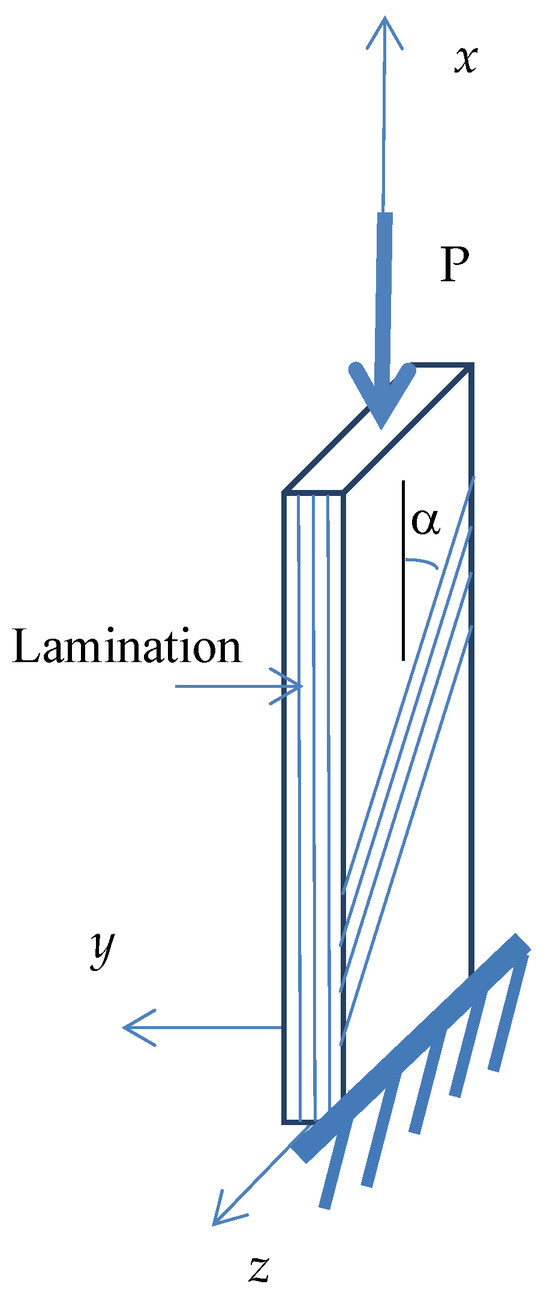
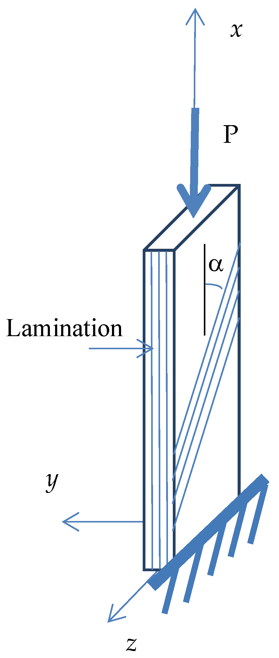
- Buckling occurs in the x–y plane about the z-axis (weak axis).
- The y-axis runs through the thickness of the plate where the composite lamination takes place, Figure 1.Figure 1. Column geometry.
- The lamination angle (α) is measured with respect to the x-axis (i.e., 0° fibers run parallel to the x-axis and 90° fibers run parallel to the z-axis). Accordingly, the angle (α) is rotated about the y-axis.
- Plane sections before bending remain planar after bending and perpendicular to the mid-surface (i.e., simple beam theory holds).
- Classical lamination theory is applicable with shear deformations ignored.
Figure 1 presents the Cartesian coordinates and the geometry of a fixed–free column. Bending takes place about the z-axis, which is the weak axis of the column. Equations (2) and (3) present the assumed displacement field based on the isotropic buckling mode:
where and v are the axial and lateral displacement, B1 and C1 are constants to be solved, and x is the distance along the axis of the column, as shown in Figure 1. The axial strain and curvature are presented in Equation (4), depending on the intermediate class of deformation:
2.2. Constitutive Equations
Stresses and strains are related by the transformed reduced stiffness matrix , presented in Equation (5) as defined in standard composite textbooks, in order to transform the principal material directions into the column coordinate system.
Accordingly, the coupled force–strain relationship was established as
where
where , , and are the extensional, coupling, and flexural rigidity coefficients, respectively. The thickness of the k-th ply is denoted by , and n is the number of different plies in the stacking sequence.
A three-dimensional (3D) rigidity matrix was established from Equation (7) using the material properties and the fiber orientations. The 3D classical lamination matrix was reduced to 1D anisotropic equivalent extensional, coupling, and flexural stiffness coefficients using static condensation after applying the zero forces and moments.
Extracting the second, third, fifth, and sixth linear equations from matrix in Equation (8) to solve the axial strain and axial curvature (, ) with respect to the other deformation components, we find the following:
Applying the inverse of matrix Q to Equation (9), the condensed deformation components are obtained in terms of the axial strain and curvature:
The axial force and in-plane moment versus the axial strain and in-plane curvature relationship is developed in terms of the generally anisotropic material properties by substituting Equation (10) into the first and fourth linear equation of the matrix in Equation (8)
where
2.3. Energy Formulation
A generalized analytical buckling formula was developed using standard Rayleigh–Ritz approximation based on the energy approach. The strain energy can be expressed in terms of the integral of the applied loads against the corresponding deformations.
The potential energy of the external loads can be expressed as
Using Equation (13) and (14), the total potential energy function is given by
Substituting Equations (2)–(4) into Equation (15), the total potential energy expression becomes the following:
By minimizing the total potential energy with respect to the unknown B1 and C1, and setting the differential expressions to zero, the following equations are obtained:
Solving Equation (17) for B1 value, we find the following:
Noticing that Equation (17) is quadratic and Equation (18) is cubic, this nonlinear system, in the unknowns B1, C1, and P, did not have a unique closed-form solution. Therefore, the critical stability matrix was considered:
where
Setting the determinant of the matrix in Equation (20) to zero, and then simplifying, one obtains the following:
2.4. Rayleigh–Ritz Buckling Formula
The nonlinear system comprising Equations (17), (18), and (22) for the three unknowns B1, C1, and P has a unique real solution , where P is given by
where
The buckling load formula presented in Equation (23) is called the standard Rayleigh–Ritz equation and is denoted by . This formula reduces down to the Euler buckling solution for fixed–free columns once the effective coupling stiffness term vanishes, that is,
However, the Rayleigh–Ritz buckling load only provides an upper bound solution for the buckling load, typically with a higher margin of error compared with FE results in cases of anisotropic layups. Accordingly, this solution was not considered further. Furthermore, the critical stability matrix, Equation (20), was pursued. Setting the determinant of the matrix in Equation (20) to zero, substituting the B1 expression from Equation (19), and solving for C1 using the general solution of a quadratic equation, we obtained the following:
In order for the C1 value to be real, the discriminant must be at least zero. By setting the discriminant to zero and manipulating its expression, a closed-form solution for the critical buckling load is derived:
The general critical buckling formula for columns with different width values other than unity is as follows:
where w is the width of the column. Equation (28) reduces down to the Euler buckling formula for fixed–free columns when the coupling term vanishes in cases of isotropic or specially orthotropic materials.
3. Numerical Formulation
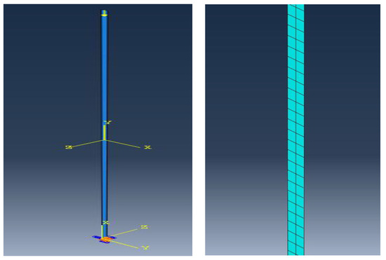
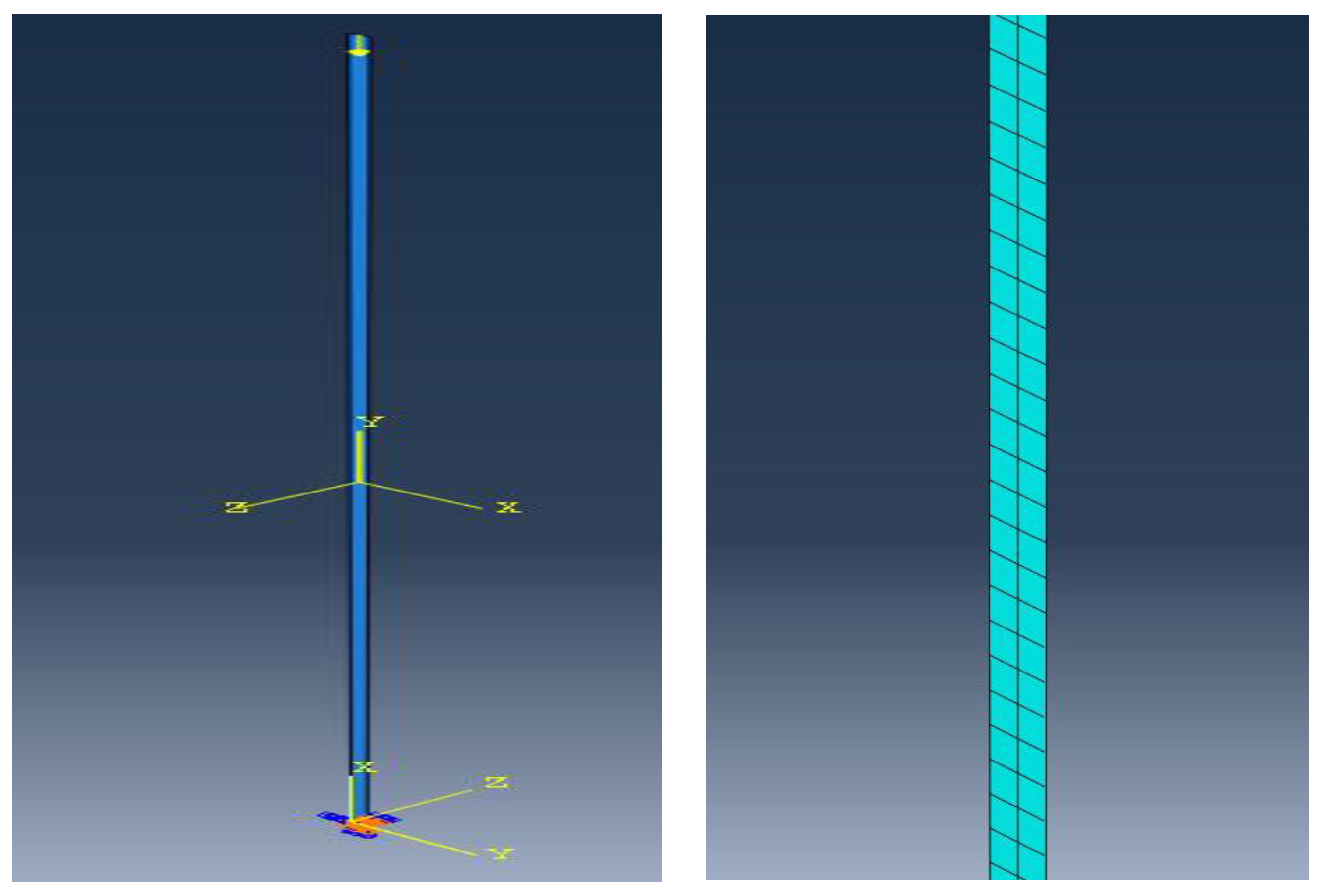
In order to validate the analytical formula for laminated anisotropic fixed–free columns derived in the previous section, finite element analysis was conducted using the commercial software package Abaqus 2016. Column models were constructed with four layers of linear elastic laminated material. Moreover, fixed supports and free ends were provided at the bottom and top of the columns, respectively. An axial compression load was applied at the top of the models, as presented in Figure 2. The quadrilateral 8-node doubly curved thick shell element (S8R) and 20-node quadratic solid element (C3D20R) were used to model the anisotropic columns in 3D space. After a sensitivity analysis, the mesh that contained 0.5 × 0.5 mm shell element size for solving a column of size 100 mm × 1.0 mm × 0.4 mm for length, width, and thickness, respectively, was found to yield converged buckling results for isotropic and anisotropic laminated members.
Figure 2.
(Left): Boundary conditions and applied load. (Right): Meshed model.
To solve for the eigenvalues and eigenvectors numerically, buckling analysis was conducted using the Lanczos solver. Based on the power method, the Lanczos technique were used to simulate eigenvalue computation for a complex Hermitian matrix in which a symmetric matrix was reduced to a tridiagonal matrix using multi-dimensional array values (recurrence relations).
To indicate the existence of pre-buckling deformation in the transverse direction and predict the nonlinear stability response of the anisotropic columns, nonlinear geometry analysis using the modified Riks technique was performed. Based on the arc length method, Riks analysis follows the equilibrium path (bifurcation points or limit points) while applying a load increment during the analysis. Equilibrium iterations converge along the arc length, forcing the constraint equation to be satisfied at every arc length increment.
4. Results and Applications
4.1. Numerical Validation
A High-Strength Graphite/Epoxy material was mainly used to simulate the composite columns, and its properties are illustrated in Table 1, obtained from typical values in an FRP textbook [22]. Table 2 presents the comparison between the analytical and numerical results for different stacking sequences of a composite column with the following dimensions for length, width, and thickness: 100 mm × 1.0 mm × 0.4 mm, respectively. The analytical results show an excellent agreement with the finite element results, with a maximum error equal to −3.60% for the balanced angle-ply layup (30/−30/60/−60) and a minimum error equal to 0.00076% for the single specially orthotropic layup (90/90/90/90). It is important to note that the layup with the maximum error yields the analytical load on the conservative side. Equation (32) was used to calculate the error values between the analytical and numerical results, where the negative and positive values indicate the lower and upper bounds for the buckling load, respectively.
Table 1.
High-Strength Graphite/Epoxy material properties.
Table 2.
Comparison of analytical and numerical buckling load for various layup sequences of Graphite/Epoxy composite column (t = 0.4 mm).
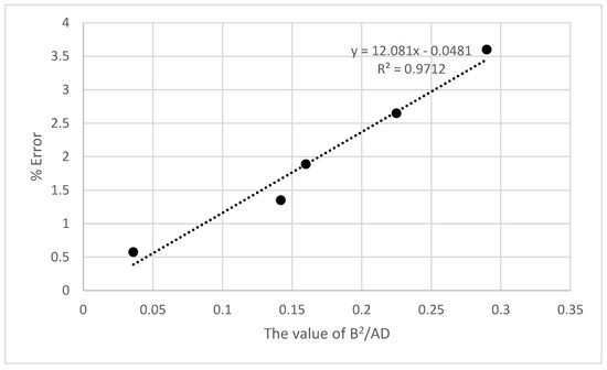
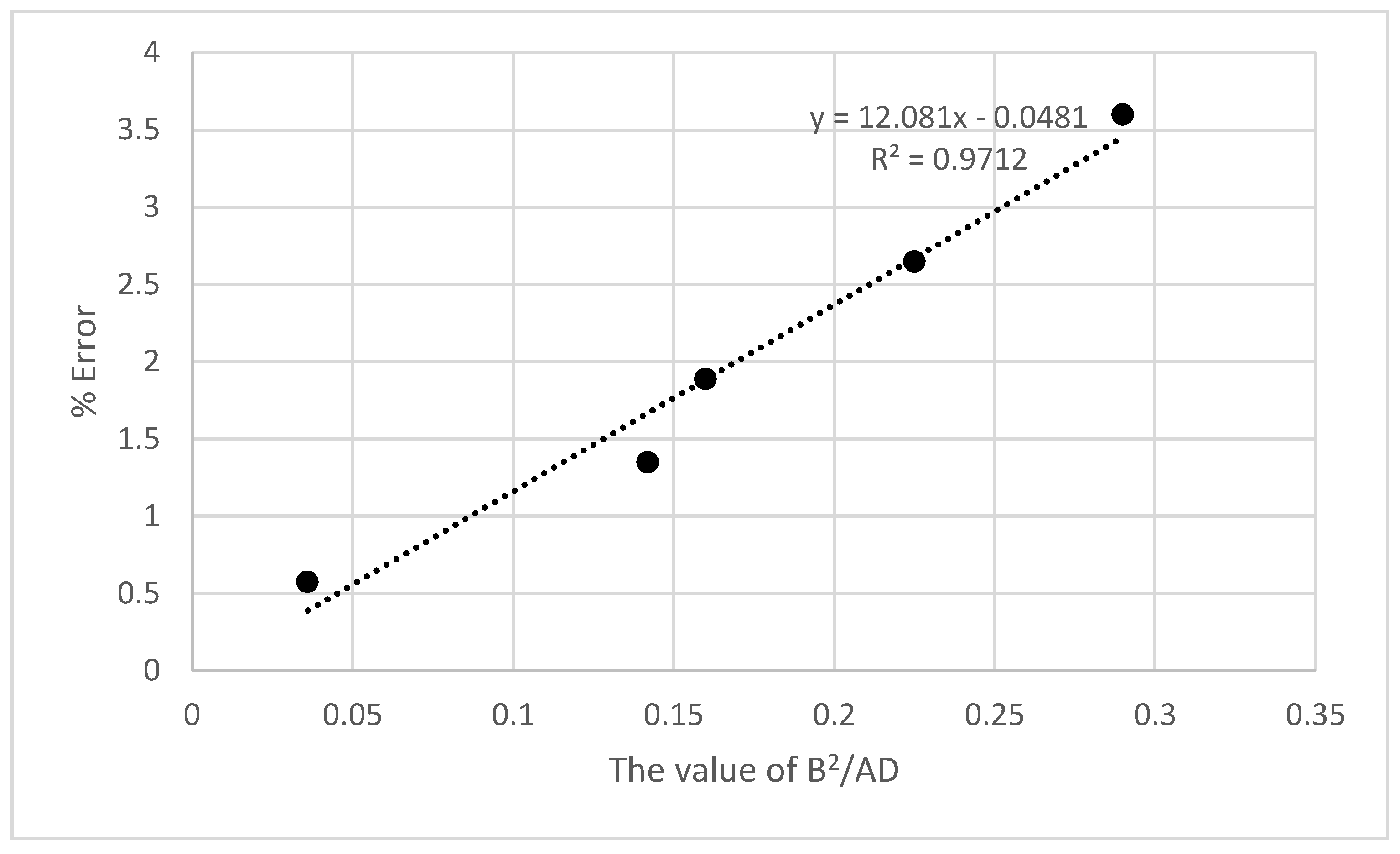
When investigating the reason for the variation in percentage errors in terms of the ply layups, it was realized that the percentage error was linearly proportional to the value of the non-dimensional variable (), which is a function of the statically condensed parameters, see Figure 3. The five layups in Table 2 with the highest percentage errors were plotted against that non-dimensional variable, as depicted in Figure 3.
Figure 3.
Correlating the percentage error with the statically condensed parameters.
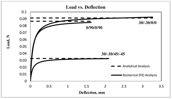
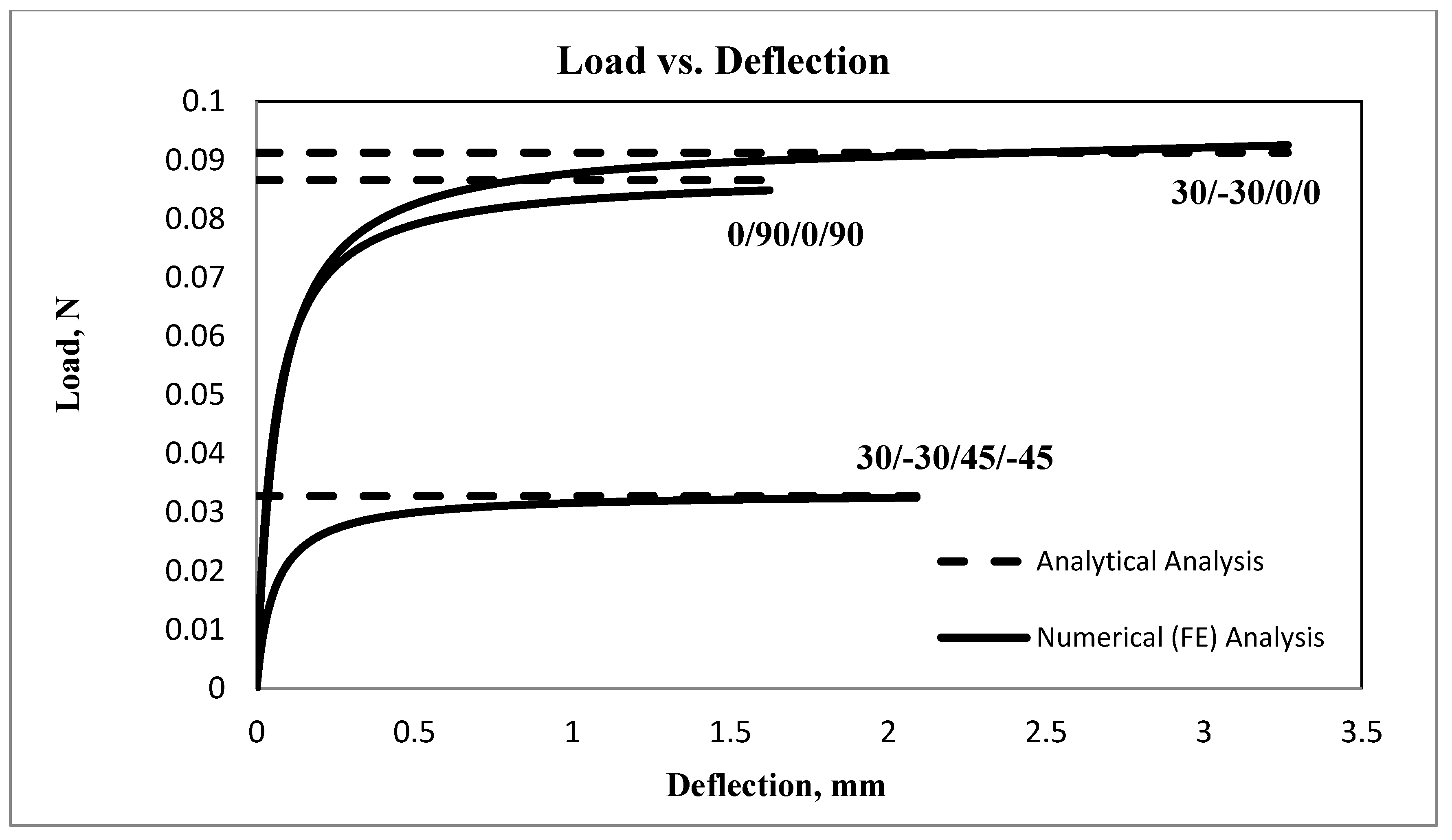
The load versus free-end displacement curve was plotted for three different stacking sequences obtained from the nonlinear finite element Riks analysis, along with the analytical solution, as shown in Figure 4. The analytical results show an excellent agreement with the Riks analysis, where the anisotropic layup (30/−30/0/0) exhibits the highest buckling load with the maximum error value. The three stacking sequences indicate the existence of transverse deformation prior to buckling.
Figure 4.
Analytical versus numerical solutions.
4.2. Parametric Study
4.2.1. Effect of Ply Orientation
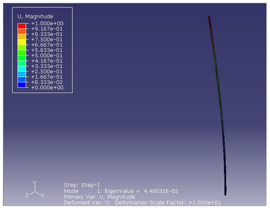
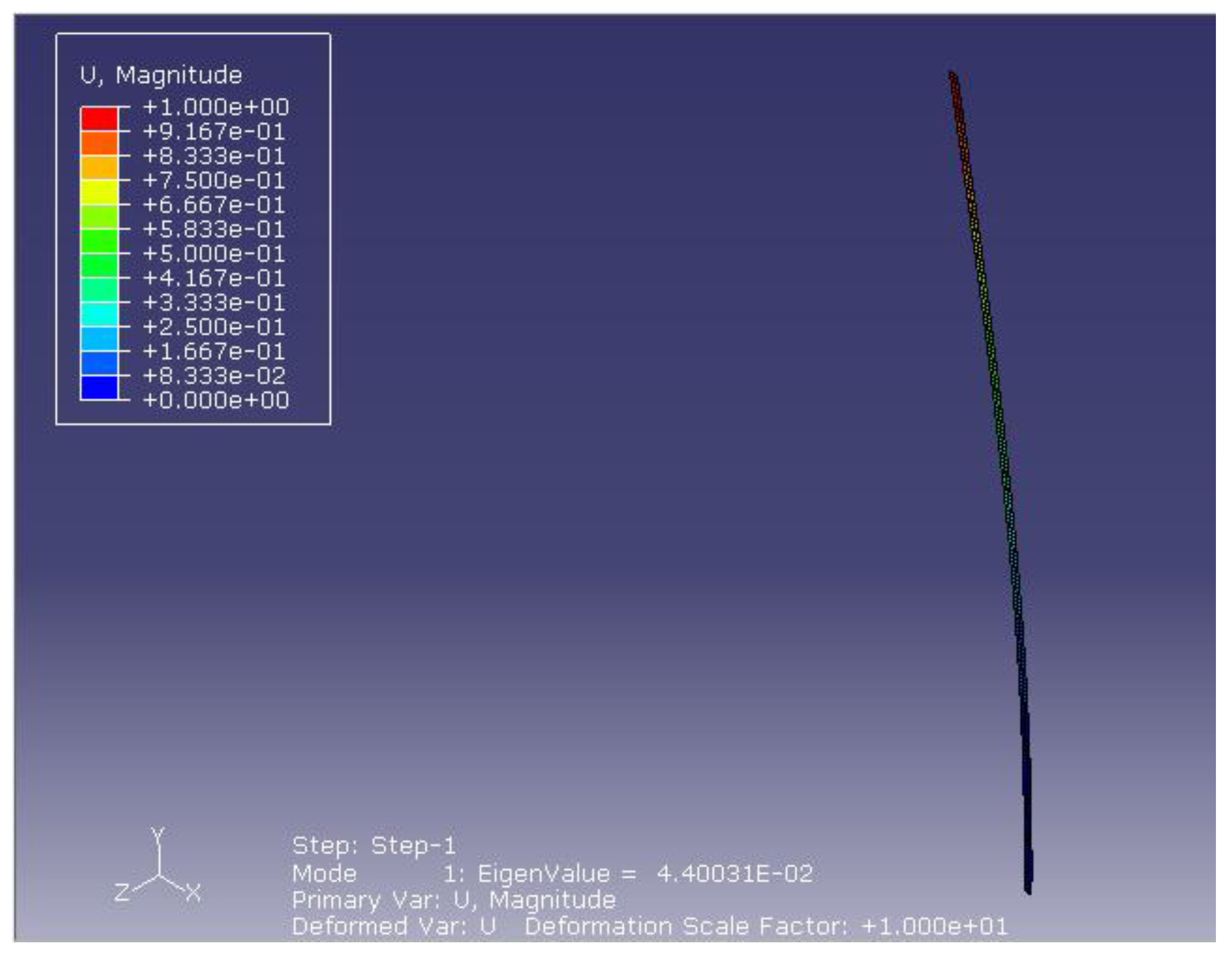
Table 2 in the previous section presents the effect of having different stacking sequences of anisotropic columns with the following dimensions for length, width, and thickness: 100 mm × 1.0 mm × 0.4 mm, respectively. The buckling load values vary between 0.19082 N and 0.01316 N for different stacking sequences. Figure 5 presents the buckling mode shape of the composite fixed–free column with the stacking sequence (30/−30/0/90) obtained from the finite element analysis.
Figure 5.
Buckling shape of fixed–free column.
4.2.2. Effect of Material Properties
The effect of having different material properties on the buckling load was investigated in this paper. High-Strength Graphite/Epoxy and S-Glass/Epoxy material properties were used, and their properties are illustrated in Table 1 and Table 3, obtained from typical values in an FRP textbook (Rasheed 2015).
Table 3.
S-Glass/Epoxy material properties.
The High-Strength Graphite/Epoxy and S-Glass/Epoxy results are presented in Table 2 and Table 4 for different stacking sequences. S-Glass/Epoxy shows lower buckling load values compared to High-Strength Graphite/Epoxy since it has a lower stiffness value along the fiber direction.
Table 4.
Analytical and numerical results for various layup sequences for S-Glass/Epoxy (t = 0.4 mm).
A hybrid material composed of High-Strength Graphite/Epoxy and S-Glass/Epoxy was used to study the effect of changing material properties on the stability of the composite columns. The S-Glass/Epoxy material properties were used for layers with orientations equal to 90° and 60°, and High-Strength Graphite/Epoxy’s properties were used for the other orientations. Table 5 reports the analytical and numerical results for various layup sequences of the hybrid material, with a maximum error of 2.35% for the balanced angle-ply layup (30/−30/60/−60) and a minimum error of 0.082% for symmetric cross-ply layup (0/90/90/0).
Table 5.
Analytical vs. numerical buckling loads for various layup sequences of hybrid Graphite and S-Glass/Epoxy composites.
4.2.3. Effect of Element Type in FE Analysis
A parametric study was conducted to investigate the effect of changing the element type in the finite element analysis of the bucking load of the composite columns. The quadratic thick shell element (S8R) and quadratic solid element (C3D20R), both with reduced integration schemes, were utilized, with an element size equal to 0.5 mm × 0.5 mm, as illustrated earlier. Table 6 reports the comparison between the analytical and numerical results for the shell and solid elements. It was observed that the shell element results showed an excellent agreement with the analytical results for all stacking sequences. On the other hand, the solid element results were noticeably off for the cross-ply and anisotropic stacking sequences, having the same mesh size as that of the shell element since solid elements have only translational degrees of freedom while shell elements have rotational degrees of freedom. Accordingly, the shell element might be more reliable than the solid element in the buckling analysis of composite members.
Table 6.
Analytical and numerical results with shell and solid elements.
4.2.4. Effect of Element Thickness
The effect of having thin and thick columns was also studied. Comparisons between the analytical and numerical results were conducted, using columns with 0.4 mm and 1.6 mm thicknesses while maintaining the same width-to-thickness ratio, equal to 2.5. Table 7 and Table 8 present comparisons between the analytical and numerical buckling load results for the Graphite/Epoxy and S-Glass/Epoxy composite columns with 1.6 mm thickness, respectively. The level of errors between the numerical solution, capable of capturing the behavior of thick shells, with the analytical solution for the thick columns is similar to that of the thin columns. This may suggest that the present formula can be successfully used to re-produce accurate results in cases of moderately thick shells.
Table 7.
Comparison of analytical and numerical buckling loads for various layup sequences of Graphite/Epoxy composite columns (t = 1.6 mm).
Table 8.
Comparison of analytical and numerical buckling loads for various layup sequences of S-Glass/Epoxy composite columns (t = 1.6 mm).
4.2.5. Effect of Column Size
A parametric study was conducted to predict the buckling load values of anisotropic laminated composite columns with different dimensions. Full-scale columns with the following dimensions for length, width, and thickness: 3000 mm × 150 mm × 4 mm, respectively, were analyzed using an eight-node quadratic thick shell element (S8R). The comparison between the analytical and numerical (FE) buckling load results of the full-scale High-Strength Graphite/Epoxy for a varied range of stacking sequences is reported in Table 9. Furthermore, the analytical solution yielded a very good agreement when compared with the finite element results. This may suggest that the proposed formula can be successfully used to re-produce accurate estimations of buckling load values for columns with different dimensions. The discrepancies indicate that the analytical results are on the conservative side for all the stacking sequences reported in Table 9. It is worth noting that the % error in Table 9 is slightly higher than that in Table 2 for the same stacking sequences, even though the L/t ratio is 750 here compared to 250 in Section 4.2.1. This may be attributed to the significantly higher w/t ratio (37.5) in this section compared to that (2.5) in the previous section, giving rise to side-edge effects inherent in the numerical solution.
Table 9.
Analytical and numerical buckling load results of full-scale High-Strength Graphite/Epoxy columns.
5. Conclusions
A generalized analytical buckling formula for anisotropic laminated composite columns with fixed–free end conditions under axial compression was developed using the critical stability matrix. The derived analytical buckling formula was expressed with respect to the effective extensional, coupling, and flexural rigidities, along with the column geometry. Furthermore, the standard Rayleigh–Ritz buckling formula yielded an upper bound solution with high percentage errors when compared to FE analysis. However, the presented analytical formula, Equation (28), exhibited an excellent agreement with the finite element analysis results. The proposed analytical formula was able to capture the complexity in the behavior of anisotropic columns for different stacking sequences, material properties, and hybrid columns, yielding an excellent agreement with the numerical analysis results. Moreover, using shell elements yielded very accurate buckling load results for all stacking sequences compared to the use of solid elements. Furthermore, the proposed analytical formula yielded accurate results for thin and moderately thick columns when compared to finite element predictions. Moreover, the presented stability solution was capable of capturing the behavior complexity of full- and small-scale anisotropic laminated composite columns. It is relevant to mention that the present formulation lends itself to the inclusion of shear deformations through the Timoshenko first-order shear deformation theory, which is a subject of future work extension.
Author Contributions
Conceptualization, H.A.R. and B.A.; Formal Analysis R.A.-M., H.A.R. and B.A.; Investigation, R.A.-M.; Validation, R.A.-M. and B.A.; Visualization, H.A.R. and B.A.; Writing—original draft, R.A.-M. and H.A.R.; Writing—review and editing, B.A. All authors have read and agreed to the published version of the manuscript.
Funding
This research received no external funding.
Data Availability Statement
All necessary data for verification purposes are listed in the paper.
Acknowledgments
The first two authors would like to thank the department of Civil Engineering at Kansas State University for partially supporting this work.
Conflicts of Interest
Author Rund Al-Masri was employed by the company DB Sterlin Consultants, Inc. The remaining authors declare that the research was conducted in the absence of any commercial or financial relationships that could be construed as a potential conflict of interest.
References
- Tarjan, G.; Kollar, L.Z. Local buckling of composite beams with edge-stiffened flanges subjected to axial load. J. Reinf. Plast. Compos. 2015, 34, 1884–1901. [Google Scholar]
- Baba, B.O. Buckling behavior of laminated composite plates. J. Reinf. Plast. Compos. 2007, 26, 1637–1655. [Google Scholar]
- Cortinez, H.V.; Piovan, M.T. Stability of composite thin-walled beams with shear deformability. Comput. Struct. 2006, 84, 978–990. [Google Scholar] [CrossRef] [Scilit]
- Aydogdu, M. Buckling analysis of cross-ply laminated beams with general boundary conditions by Ritz method. Compos. Sci. Technol. 2006, 66, 1248–1255. [Google Scholar]
- Afsharmanesh, B.; Ghaheri, A.; Taheri-Behrooz, F. Buckling and vibration of laminated composite circular plate on Winkler-type foundation. Steel Compos. Struct. 2014, 17, 1–19. [Google Scholar]
- Kayat, M.; Poorveis, D.; Moradi, S. Buckling analysis of laminated composite cylindrical shell subjected to lateral displacement-dependent pressure using semi-analytical finite strip method. Steel Compos. Struct. 2016, 22, 301–321. [Google Scholar] [CrossRef] [Scilit]
- Dong, J.; Ma, X.; Zhuge, Y.; Mills, J.E. Shear buckling analysis of laminated plates on tensionless elastic foundations. Steel Compos. Struct. 2017, 24, 697–709. [Google Scholar]
- Shnabl, S.; Planinc, I.; Turk, G. Buckling loads of two-layer composite columns with interlayer slip and stochastic material properties. J. Eng. Mech. 2013, 139, 961–966. [Google Scholar]
- Herencia, J.E.; Weaver, P.M.; Friswell, M.I. Closed-form solutions for buckling of long anisotropic plates with various boundary conditions under axial compression. J. Eng. Mech. 2010, 136, 1105–1114. [Google Scholar]
- Ovesy, H.R.; Ghannadpour, S.A.M.; Sherafat, M.H. Buckling analysis of laminated composite plates using higer order semi-analytical finite strip method. Appl. Compos. Mater. 2010, 17, 69–80. [Google Scholar]
- Matsunaga, H. Free vibration and stability of angle-ply laminated composite and sandwich plates under thermal laoding. Compos. Struct. 2007, 77, 249–262. [Google Scholar] [CrossRef] [Scilit]
- Pandey, M.D.; Sherbourne, A.N. Buckling of anisotropic composite plates under stress gradient. J. Eng. Mech. 1991, 117, 260–275. [Google Scholar] [CrossRef] [Scilit]
- Rasheed, H.A.; Yousif, O.H. Buckling of thin laminated orthotropic rings/long cylinders under external pressure. Int. J. Struct. Stab. Dyn. 2002, 1, 485–507. [Google Scholar] [CrossRef] [Scilit]
- Timarci, T.; Aydogdu, M. Buckling of symmetric cross-ply square plates with various boundary conditions. Compos. Struct. 2005, 68, 381–389. [Google Scholar] [CrossRef] [Scilit]
- Sun, L.; Harik, I.E. Buckling of stiffened antisymmetric laminated plates. J. Eng. Mech. 2013, 139, 1110–1123. [Google Scholar] [CrossRef] [Scilit]
- Harik, I.E.; Salamoun, G.L. The analytical strip method of solution for stiffened rectangular plates. Comput. Struct. 1988, 29, 283–291. [Google Scholar] [CrossRef] [Scilit]
- Falkowicz, K. Validation of Extension-Bending and Extension-Twisting Coupled Laminates in Elastic Element. Adv. Sci. Technol. Res. J. 2023, 17, 309–319. [Google Scholar] [CrossRef] [Scilit]
- Bisheh, H. Natural frequencies for bending vibrations of smart laminated composite plates reinforced with bamboo fibres. Smart Mater. Methods 2024, 1, 351–374. [Google Scholar] [CrossRef] [Scilit]
- Al-Masri, R.A.; Rasheed, H.A. Analytical and Finite Element Buckling Solutions of Fixed-Fixed Anisotropic Laminated Composite Columns under Axial Compression. Int. J. Struct. Stab. Dyn. 2017, 17, 1750103. [Google Scholar] [CrossRef] [Scilit]
- Rasheed, H.A.; Al-Masri, R.A.; Alali, B. Closed Form Stability Solution of Simply Supported Anisotropic Laminated Composite Plates under Axial Compression Compared with Experiments. Eng. Struct. 2017, 151, 327–336. [Google Scholar] [CrossRef] [Scilit]
- Al-Masri, R.A.; Rasheed, H.A. Buckling Solutions of Clamped-Pinned Anisotropic Laminated Composite Columns under Axial Compression using Bifurcation Approach and Finite Elements. Thin-Walled Struct. 2018, 123, 206–213. [Google Scholar] [CrossRef] [Scilit]
- Rasheed, H.A. Strengthening Design of Reinforced Concrete with FRP; CRC Press: New York, NY, USA, 2015. [Google Scholar]

Disclaimer/Publisher’s Note: The statements, opinions and data contained in all publications are solely those of the individual author(s) and contributor(s) and not of MDPI and/or the editor(s). MDPI and/or the editor(s) disclaim responsibility for any injury to people or property resulting from any ideas, methods, instructions or products referred to in the content. |
© 2025 by the authors. Licensee MDPI, Basel, Switzerland. This article is an open access article distributed under the terms and conditions of the Creative Commons Attribution (CC BY) license (https://creativecommons.org/licenses/by/4.0/).