


Highlights
What are the main findings?
- Working voltage regulated Ni–Gr coating morphology and graphene dispersion.
- A 7 V voltage produced a dense coating with the lowest graphene defect ratio.
- The 7 V coating achieved 395 HV, low Icorr, and 145 W/(m·K) conductivity.
- Excessive voltage caused roughening, pores, and graphene agglomeration.
What are the implications of the main findings?
- Voltage optimization enables multifunctional Ni–Gr coatings for brass heat sinks.
- Moderate polarization promotes Ni nucleation and graphene incorporation.
- Graphene dispersion is critical for wear, corrosion, and heat-transfer performance.
- Electro-brush plating offers a practical route to protect copper-based components.
Abstract
To improve the surface service durability and heat-transfer performance of brass heat-dissipation components, Ni–graphene (Ni–Gr) composite coatings were prepared on brass substrates by electro-brush plating, and the effects of working voltage on the coating microstructure and overall performance were investigated. The coating thickness ranged from 6.667 to 19.334 μm. The results show that the coating prepared at 7 V had a thickness of 8.524 μm, a dense microstructure, relatively uniform graphene dispersion, and the lowest Raman ID/IG ratio of 1.2146, thereby exhibiting the best overall performance. The microhardness of this coating reached 395 HV, which was approximately 190% and 127% higher than those of the brass substrate and pure Ni coating, respectively. Its corrosion current density in 3.5 wt.% NaCl solution decreased to 1.0143 × 10⁻⁵ A/cm2, corresponding to a 90.4% reduction relative to the pure Ni coating. The room-temperature thermal conductivity of the coating/brass composite specimen reached 145 W/(m·K), which was 29.5% higher than that of the brass substrate. When the working voltage increased to 9–11 V, although the coatings became thicker, surface nodules coarsened, pores/pinholes increased, and graphene agglomeration intensified, leading to declines in mechanical properties, corrosion resistance, and thermal conductivity. These results demonstrate that an appropriate working voltage is beneficial for coordinating Ni nucleation/growth and graphene co-deposition, and is a key processing parameter for obtaining high-performance Ni–Gr composite coatings for brass heat-dissipation components.
1. Introduction
With the rapid development of 5G communication, new energy vehicles, high-power electronic devices, and related fields, the integration level and power density of electronic equipment have continuously increased. Consequently, the reliability of heat-dissipation systems has become a critical factor limiting device service life and performance stability [1,2]. Owing to its excellent thermal conductivity, good formability, and relatively low cost, brass is widely used in the fabrication of various heat-dissipation components [3,4,5]. However, during long-term service, brass substrates are susceptible to surface wear, oxidation, and corrosion in aggressive media, which increase surface roughness and thermal resistance, ultimately leading to pronounced degradation of heat-dissipation performance and seriously compromising the operational safety of electronic devices [6,7,8,9]. Therefore, developing surface modification technologies that combine high hardness, excellent wear and corrosion resistance, and good thermal conductivity is of significant engineering value for improving the overall service performance of copper-based heat-dissipation components.
Surface coating technology is one of the most economical and effective approaches for improving the surface properties of metallic materials [10,11,12,13]. Among various surface treatment methods, electro-brush plating has been widely applied in the fields of surface strengthening and remanufacturing of industrial equipment, owing to its simple apparatus, operational flexibility, high deposition rate, and strong coating–substrate adhesion [14,15]. Nickel-based electro-brush coatings have become a promising system for surface modification because of their favorable mechanical properties, corrosion resistance, and excellent bonding compatibility with copper substrates [16,17]. However, pure Ni coatings still suffer from relatively low hardness, insufficient wear resistance, and limited thermal conductivity, making it difficult to meet the requirements of high-power heat-dissipation components for synergistically enhanced multifunctional performance [18].
To further improve the comprehensive properties of Ni-based coatings, the incorporation of second-phase reinforcing particles into the Ni matrix to fabricate composite coatings has become a research hotspot. Gao et al. [19] prepared Ni/diamond composite coatings containing self-lubricating particles on 304 stainless steel by electro-brush plating. The wear resistance of the coatings was improved by adding diamond particles and different types of lubricating particles. Graphene, as a two-dimensional carbon nanomaterial, possesses an ultrahigh thermal conductivity of approximately 5300 W/(m·K), excellent mechanical strength with a tensile strength of up to 130 GPa, good chemical stability, and self-lubricating properties. Therefore, it is considered an ideal reinforcing phase for Ni-based composite coatings [20,21]. Xu et al. [22] prepared Ni–graphene composite coatings on Q235 steel plates by electro-brush plating to mitigate fluoride ion corrosion. Zhang et al. [23] fabricated GO-containing Ni-based nanocomposite coatings using electro-brush plating; the uniform distribution of GO nanosheets in the coating contributed to a stable and durable lubricating effect, thereby enabling an extremely stable friction process. Qi et al. [24] prepared Ni–graphene oxide (GO) composite coatings on steel by electro-brush plating and compared the friction behavior of Ni–GO nanocomposite coatings with that of GO-free Ni coatings. The results showed that the friction coefficient of the composite coating was much lower than that of the GO-free Ni coating. Jagannadham et al. [25] prepared Cu–Gr composite films by electrochemical co-deposition and reported that, when the composite-film thickness exceeded 200 μm, the thermal conductivity at 300 K increased from approximately 380 W/(m·K) for pure electrodeposited Cu films to 460 W/(m·K), indicating the potential of a rational graphene addition to improve thermal transport in metal-matrix composites. Yang et al. [26] investigated the co-deposition and thermal conduction behavior of Ni–rGO composite coatings on Cu substrates, and found that the thermal diffusivity and thermal conductivity of the coatings varied with deposition current density, with relatively good thermal performance obtained at 5 A/dm2. This indicates that thermal transport in Ni–graphene composite coatings depends not only on the intrinsic thermal conductivity of graphene, but also on its co-deposition state and the coating microstructure.
However, many previous studies have focused primarily on optimizing a single property, whereas the integrated regulation of mechanical properties, tribological behavior, corrosion resistance, and thermal conductivity remains insufficiently addressed. In this work, the effects of working voltages from 5 to 11 V on the microstructure, phase composition, graphene structural integrity, microhardness, friction and wear behavior, corrosion resistance, and thermal conductivity of Ni–Gr composite coatings were systematically investigated. The mechanism by which working voltage regulates the structure and properties of Ni–Gr composite coatings is clarified, providing theoretical support for surface modification of Cu-based heat sinks.
2. Materials and Methods
2.1. Materials and Plating Solution
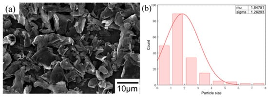
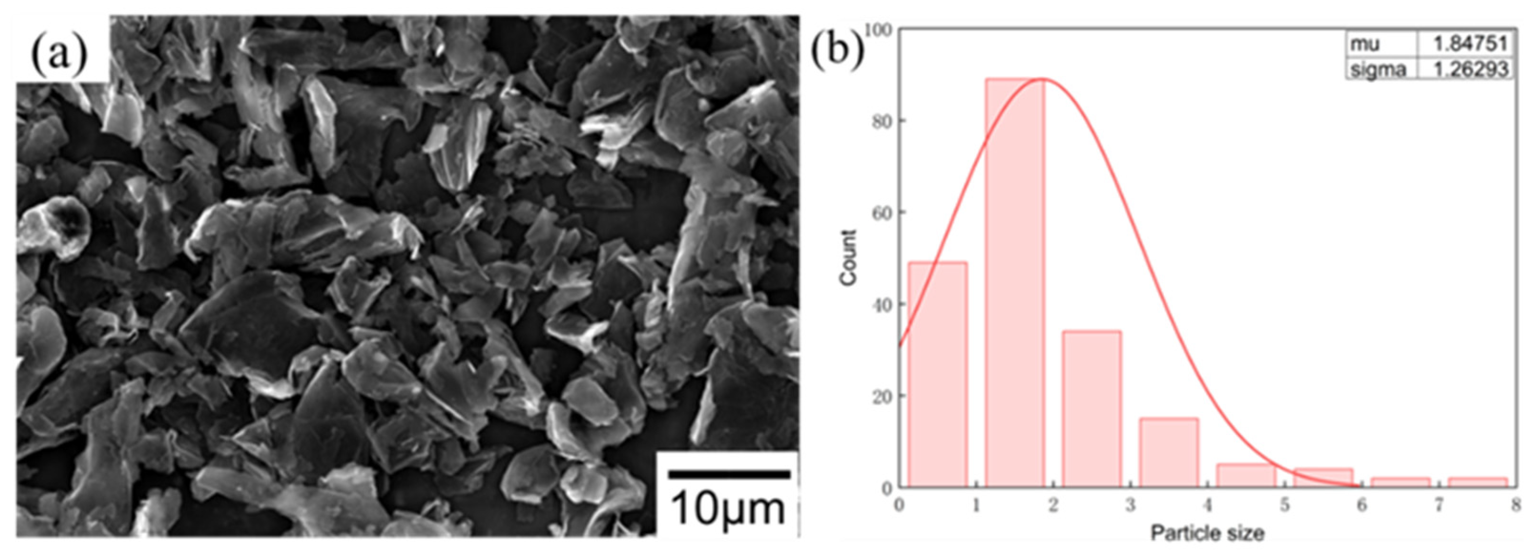
Brass plates with dimensions of 30 mm × 40 mm × 1 mm were used as substrates. Before deposition, the substrate surfaces were sequentially ground with 600#, 800#, 1000#, and 2000# abrasive papers. The substrates were then degreased and activated by alkaline and acid cleaning, respectively, ultrasonically cleaned in deionized water, and dried for subsequent use. The SEM morphology and particle-size distribution of the graphene powder used in the experiments are shown in Figure 1. The graphene powder had a purity of 99%. The supplier specified a particle size of 7–10 μm, whereas SEM statistics showed that the lateral size of individual sheets was mainly distributed in the range of 0.1–5 μm. This discrepancy is mainly attributable to the disintegration of graphene agglomerates during ultrasonic dispersion and to the fact that SEM statistics were based on individual sheets rather than agglomerated particles. A Watts-type nickel plating solution was used, with the following composition: NiSO4·6H2O 220 g/L, NiCl2 45 g/L, H3BO3 40 g/L, and sodium dodecyl sulfate 0.1 g/L. The graphene concentration was set to 750 mg/L. To improve the dispersion stability of graphene in the plating solution, the graphene-containing electrolyte was first magnetically stirred for 30 min and then ultrasonically dispersed for 2 h.
Figure 1.
Graphene powder: (a) SEM morphology; (b) particle-size distribution.
2.2. Electro-Brush Plating Process
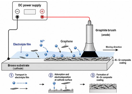
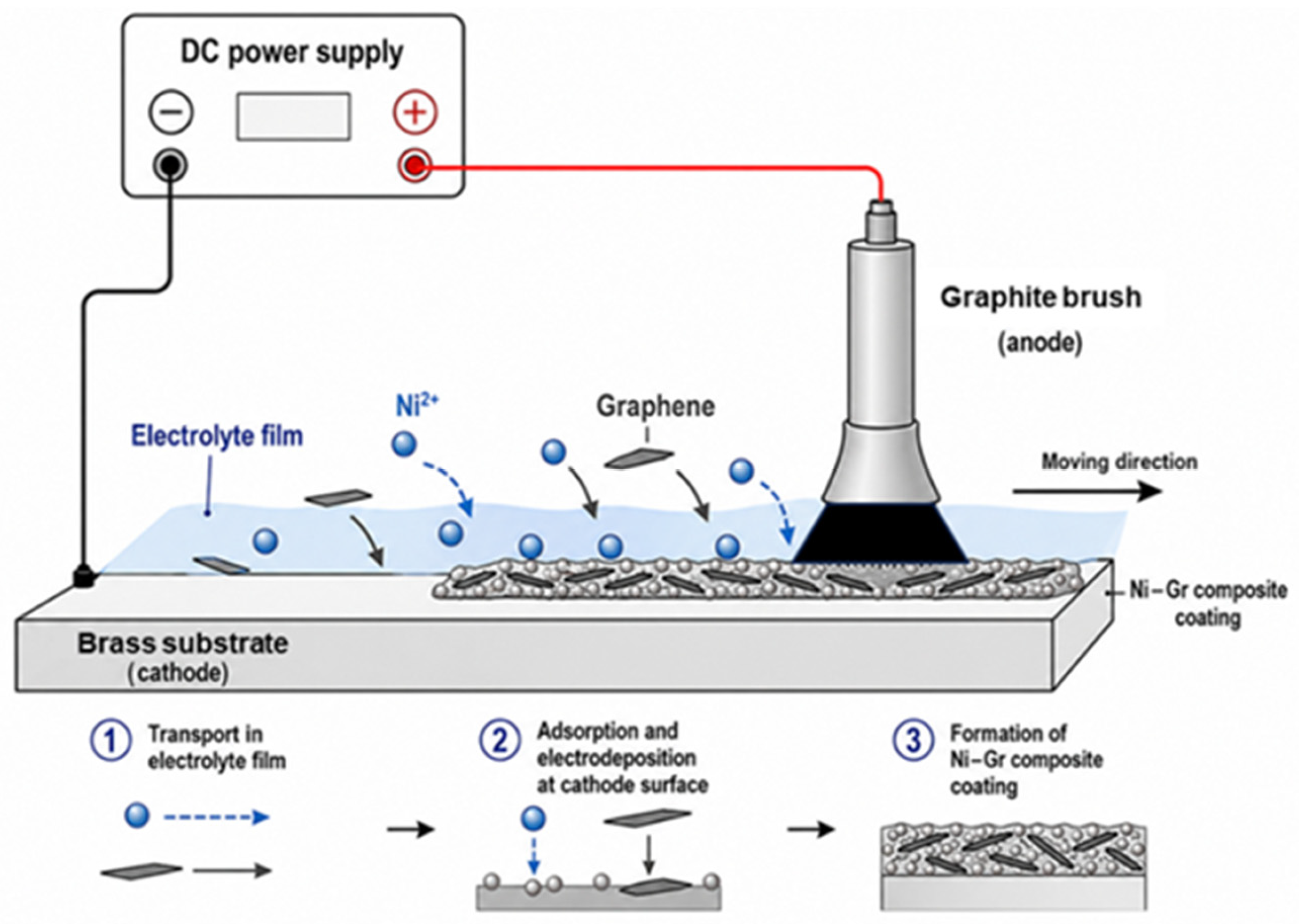
During electro-brush plating, the pretreated brass specimen served as the cathode, and the plating brush wrapped with cotton served as the anode. The electrodeposition process is illustrated in Figure 2. The electrolyte pH was fixed at 3.5, the temperature was 50 °C, the graphene concentration was 750 mg/L, the brushing speed was 6 cm/s, and the deposition time was 15 min. The working voltages were set to 5, 7, 9, and 11 V. The detailed electro-brush plating parameters are summarized in Table 1. After deposition, the specimens were rinsed with deionized water, ultrasonically cleaned in absolute ethanol, and dried.
Figure 2.
Schematic diagram of the electrodeposition process.
Table 1.
Electro-brush plating parameters used for preparing Ni–Gr composite coatings.
2.3. Characterization and Property Tests
The coating surface morphology and surface elemental distribution were observed and analyzed using an SEM5000 scanning electron microscope equipped with energy-dispersive spectroscopy (EDS; SEM, CIQTEK, Hefei, China) in secondary-electron mode (ETD-SE), with an accelerating voltage of 10 kV and a working distance of 10.11 mm. The three-dimensional surface morphology and surface roughness of the coatings were characterized using a confocal laser scanning microscope (LSM 800, Carl Zeiss, Jena, Germany). Multiple random regions parallel to the brush-plating direction were selected for measurement, and at least five repeated measurements were performed. The phase composition and crystallographic orientation of the coatings were analyzed using an Empyrean X-ray diffractometer (XRD; Malvern Panalytical, Almelo, The Netherlands). Graphene in the coatings was characterized by Raman spectroscopy (Horiba LabRAM HR Evolution, Kyoto, Japan). The surface chemical states of the coating elements were analyzed using X-ray photoelectron spectroscopy (XPS; Thermo Scientific K-Alpha, Waltham, MA, USA). Microhardness was measured using an HV-50 Vickers hardness tester (Laizhou Huayin Testing Instrument Co., Ltd., Laizhou, China) under a load of 3 N and a dwell time of 15 s; at least five indentations were tested for each sample. The tribological behavior of the coatings was evaluated using a UMT-2 friction and wear tester (Bruker Corporation, Billerica, MA, USA) with a GCr15 steel ball as the counterpart, a load of 2 N, and a test duration of 30 min; each sample was tested three times. Tafel polarization curves and electrochemical impedance spectroscopy (EIS) spectra were measured in 3.5 wt.% NaCl solution using a CHI660E electrochemical workstation (CH Instruments, Shanghai, China). The room-temperature thermal properties of the coating/substrate composite specimens were measured at 25 °C using an LFA467 laser flash apparatus (Netzsch, Selb, Germany), with three points tested for each sample.
3. Results and Discussion
3.1. Surface Morphology, Cross-Sectional Thickness, and Elemental Distribution
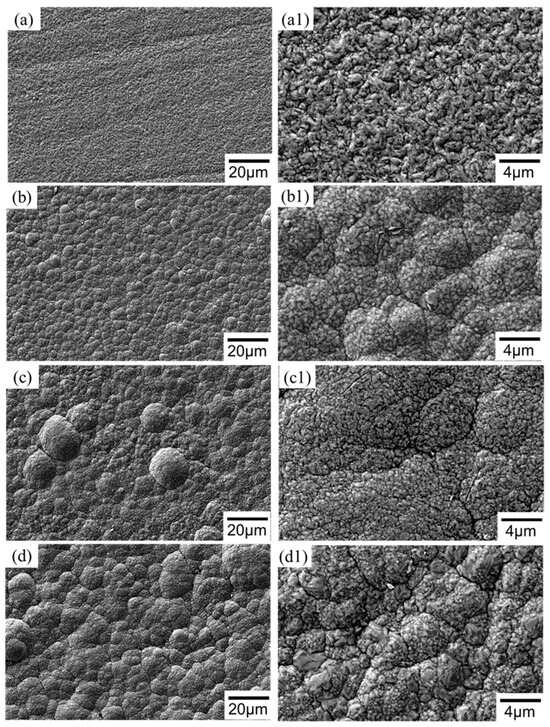
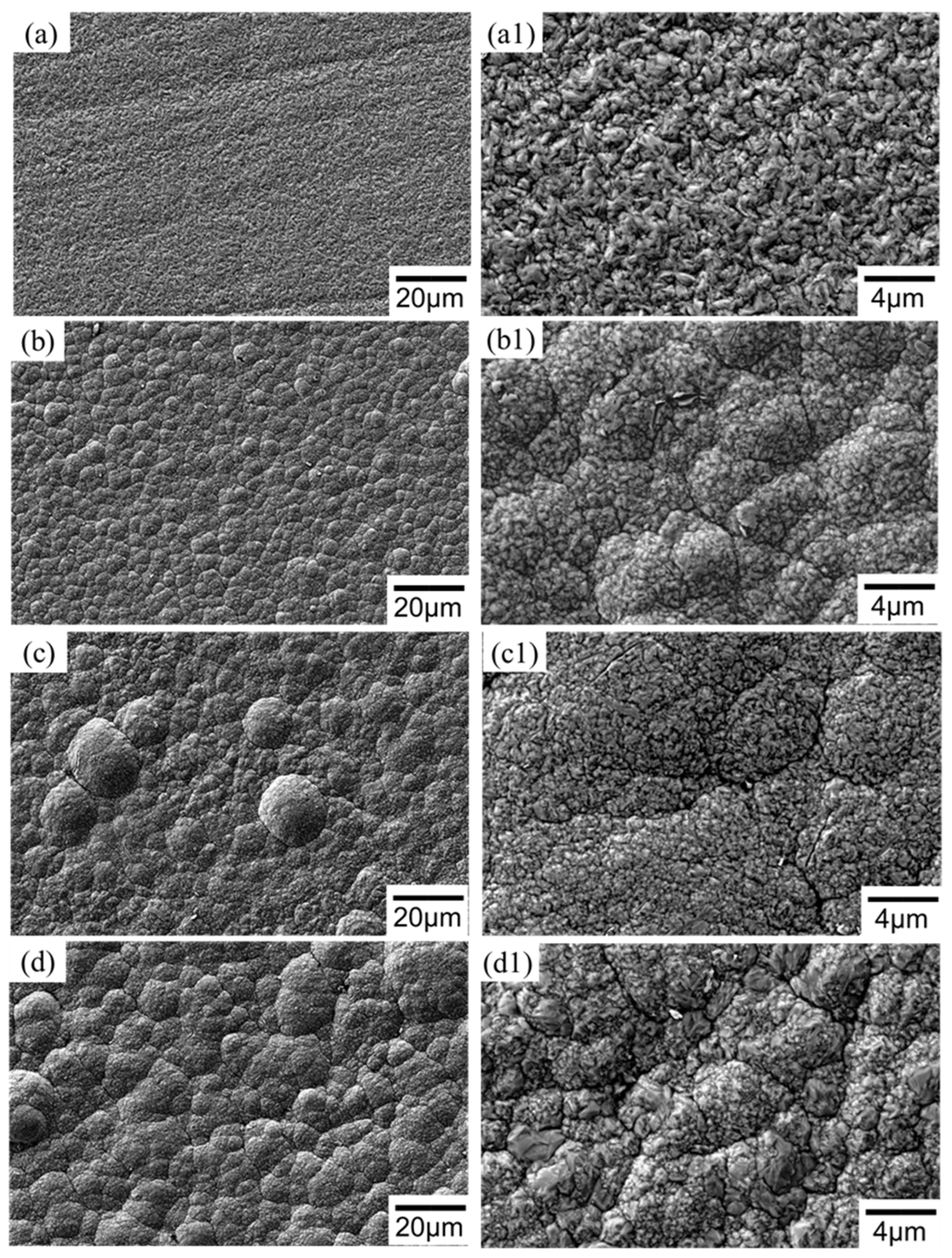
Figure 3 shows the low- and high-magnification SEM surface morphologies of the Ni–Gr composite coatings prepared at different working voltages. The SEM images of the coatings prepared at different voltages were quantitatively analyzed using ImageJ (version 1.54f). The image-analysis results showed that the surface-projected defect area fractions of the 5, 7, 9, and 11 V samples were 27.33%, 20.03%, 41.15%, and 44.11%, respectively. As shown in Figure 3a,a1, the coating surface prepared at 5 V was generally flat; however, lamellar and wrinkled structures were observed at high magnification, which were presumed to be locally exposed graphene sheets or graphene sheets not fully embedded in the Ni matrix. This indicates that, at low working voltage, the Ni2+ reduction rate was slow and coating growth was insufficient. Although graphene could adsorb on the cathode surface, its stable incorporation and uniform encapsulation were limited. When the working voltage increased to 7 V, the coating in Figure 3b,b1 exhibited a uniform, fine nodular structure and a relatively dense surface, indicating that moderate cathodic polarization was beneficial for increasing the Ni nucleation density and promoting relatively uniform graphene incorporation into the coating. With a further increase in voltage to 9 V, more pronounced spherical protrusions and local cracks appeared on the surface in Figure 3c,c1, suggesting that the accelerated deposition rate increased surface roughness. At 11 V, the coating surface particles in Figure 3d,d1 became markedly coarser and were accompanied by agglomeration and pore defects, indicating that rapid deposition, local current concentration, and hydrogen-evolution side reactions caused by excessive voltage weakened the microstructural uniformity of the coating. Therefore, the Ni–Gr composite coating obtained at 7 V exhibited superior compactness and surface uniformity.
Figure 3.
SEM surface morphologies of Ni–Gr composite coatings prepared at different working voltages: (a,a1) 5 V; (b,b1) 7 V; (c,c1) 9 V; and (d,d1) 11 V. Panels (a–d) show low-magnification images, and panels (a1–d1) show high-magnification images.
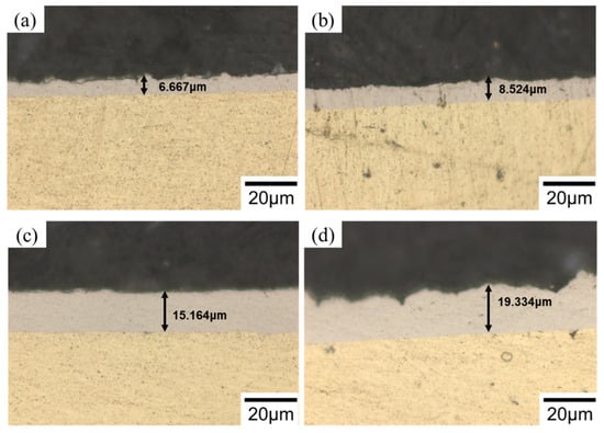
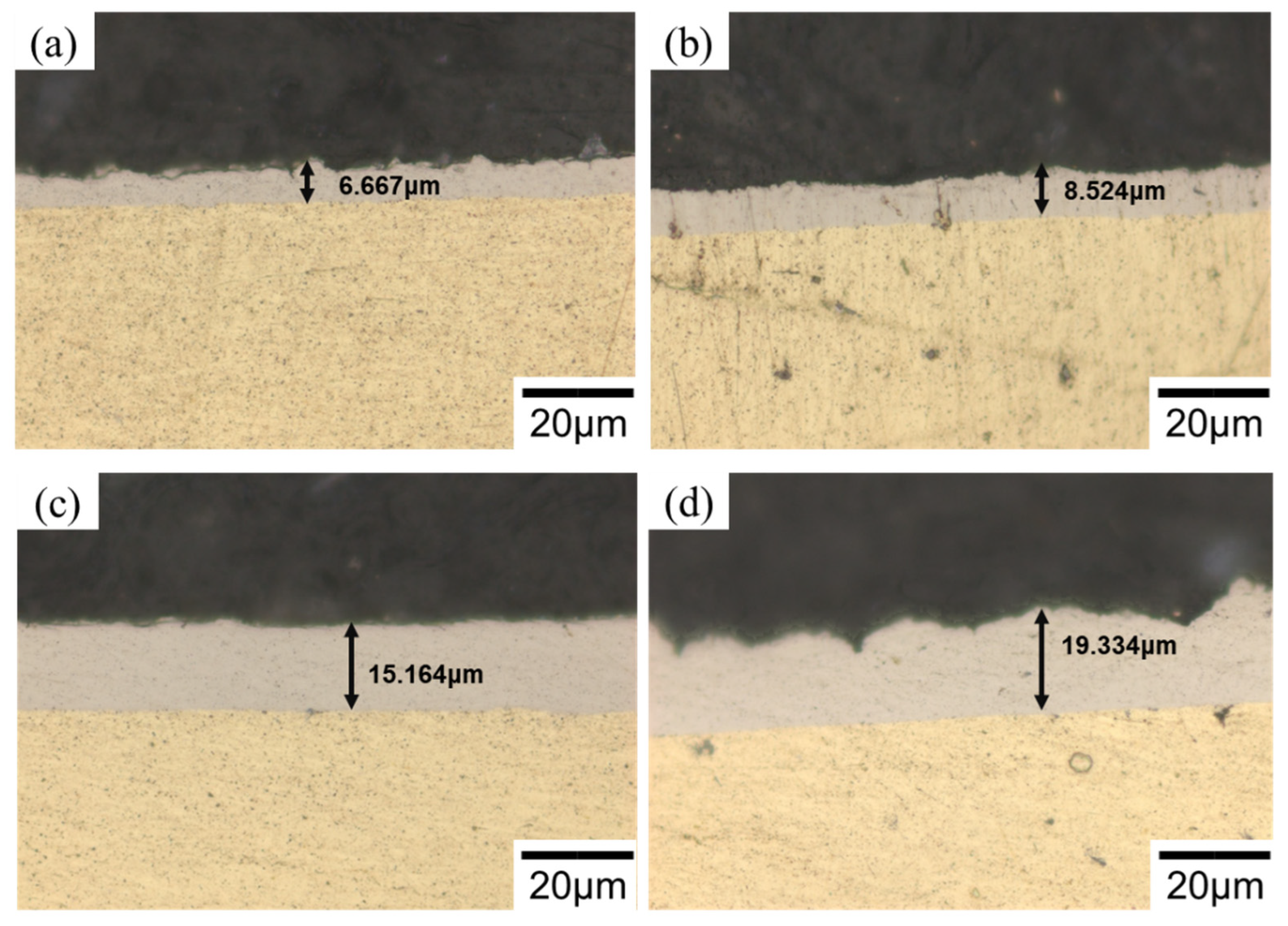
Figure 4 shows the cross-sectional morphologies of the coatings prepared at different voltages, and Table 2 summarizes their surface roughness values. As the working voltage increased from 5 to 11 V, the coating thickness increased from 6.667 and 8.524 μm to 15.164 and 19.334 μm, respectively, showing a clear increasing trend. This is consistent with the increased Ni2+ reduction rate and deposition flux at higher voltages. However, an increase in thickness does not necessarily indicate improved coating quality. Although the 9 and 11 V samples were thicker, they exhibited higher surface and interfacial roughness and reduced microstructural uniformity. By contrast, the 7 V sample achieved a favorable balance among thickness, compactness, and surface uniformity.
Figure 4.
Cross-sectional morphologies of Ni–Gr composite coatings prepared at different working voltages: (a) 5 V; (b) 7 V; (c) 9 V; and (d) 11 V.
Table 2.
Surface roughness of Ni–Gr composite coatings prepared at different working voltages.
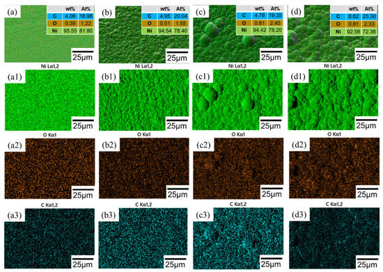
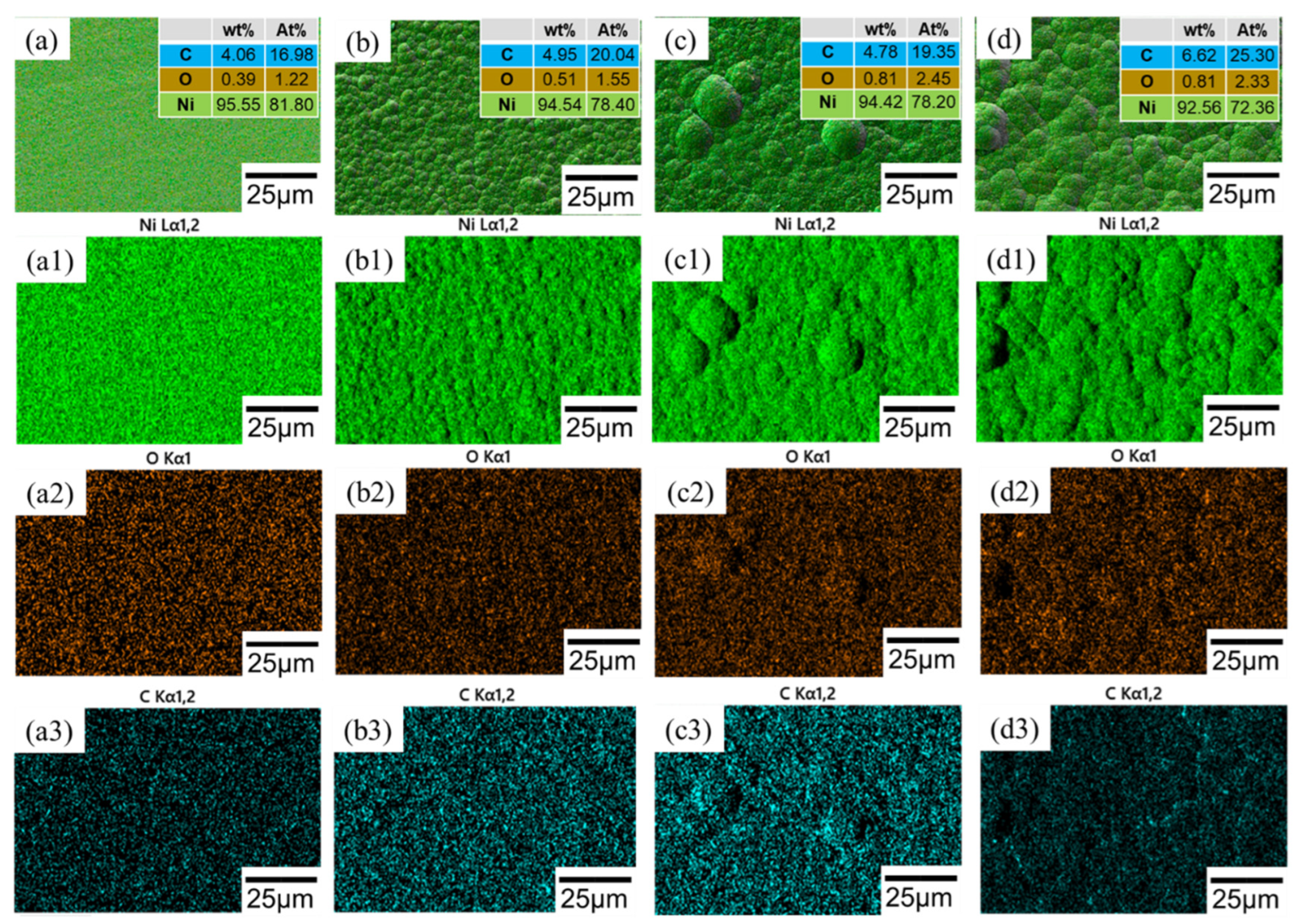
The EDS mapping results are shown in Figure 5. The surfaces of all samples were mainly composed of Ni, C, and O, indicating that graphene participated in co-deposition and was embedded in the Ni-based coating. The C content increased from 4.06 wt.% at 5 V to 4.95 wt.% at 7 V, indicating that an appropriate increase in working voltage facilitated the migration and embedding of graphene sheets toward the cathode surface. At 9 V, the C content was 4.78 wt.%, close to that at 7 V; however, the C distribution around local protrusions became less uniform. At 11 V, the apparent C content increased to 6.62 wt.%, but the areal distribution became more nonuniform, suggesting that the high carbon signal may have originated from local graphene enrichment or agglomeration.
Figure 5.
EDS elemental mapping of Ni–Gr composite coatings prepared at different working voltages: (a,a1–a3) 5 V; (b,b1–b3) 7 V; (c,c1–c3) 9 V; and (d,d1–d3) 11 V. Panels (a–d) show the surface morphology and composition, while panels (a1–d1), (a2–d2), and (a3–d3) show the elemental distributions of Ni, O, and C, respectively.
3.2. Phase Composition
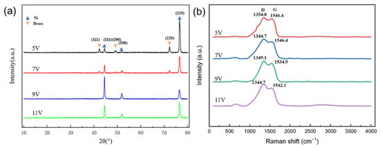
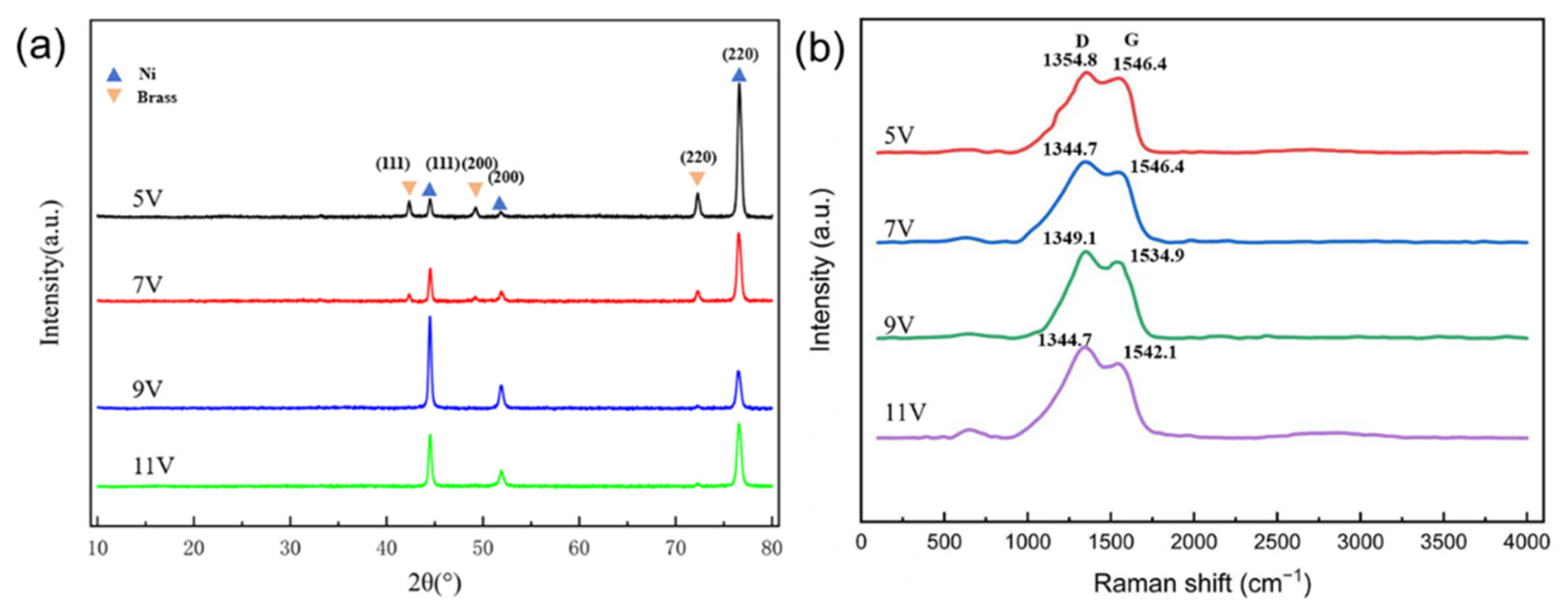
Figure 6a shows the XRD patterns of the Ni–Gr composite coatings prepared at different working voltages. All samples exhibited diffraction peaks at 2θ values of approximately 44.5°, 51.8°, and 76.4°, corresponding to the (111), (200), and (220) crystal planes of face-centered cubic Ni, respectively. No obvious nickel oxide or other impurity phases were detected. Because of the low graphene content, limited stacking order, and the masking effect of the metallic matrix background, no obvious characteristic graphene peak was observed in the XRD patterns. Based on the full width at half maximum of the Ni(111), Ni(200), and Ni(220) peaks, the apparent coherent domain size was estimated using the Scherrer equation [27,28,29]. The three-peak average domain sizes of the 5, 7, 9, and 11 V samples were 21.07, 20.82, 23.03, and 23.74 nm, respectively. The relative intensities of the Ni peaks also changed with voltage. The 5 and 7 V samples mainly showed a preferred Ni(220) orientation, the Ni(111) orientation was relatively enhanced at 9 V, and the preferred orientation weakened at 11 V. Previous studies have shown that the texture of Ni coatings is sensitive to cathodic overpotential, local current density, interfacial adsorption state, and co-deposition of second-phase particles [30,31,32,33,34]. As the working voltage increased, the Ni2+ reduction rate and deposition flux increased, altering the competition between nucleation and growth on different crystal planes. When the voltage further increased to 11 V, rapid deposition, hydrogen evolution, local pH changes, and graphene agglomeration disturbed oriented crystal growth, leading to domain coarsening and weakening of the preferred orientation. Figure 6b shows the Raman spectra of the coatings, and Table 3 lists the ID/IG ratios of the Ni–Gr composite coatings prepared at different working voltages. The D and G bands of graphene were observed under all voltage conditions, confirming successful incorporation of graphene into the Ni matrix. The D band reflects defect-induced scattering, whereas the G band corresponds to the vibration of the sp2 carbon skeleton. According to the changes in peak intensity, ID/IG first decreased and then increased with increasing working voltage, reaching the lowest value at 7 V. This indicates that graphene had a lower defect degree and better structural integrity under this condition. At 5 V, the deposition driving force was insufficient and the graphene-capture efficiency was limited. At 9 and 11 V, the current-induced thermal effect, local rapid deposition, and hydrogen-evolution side reactions caused by the higher voltage may have induced graphene-sheet agglomeration and structural defects.
Figure 6.
(a) XRD patterns and (b) Raman spectra of Ni–Gr composite coatings prepared at different working voltages.
Table 3.
Raman ratios of Ni–Gr composite coatings deposited under different working voltages.
3.3. Surface Chemical State and Interfacial Characteristics
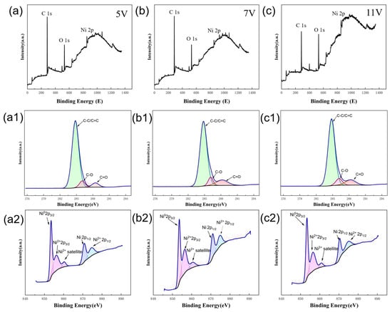
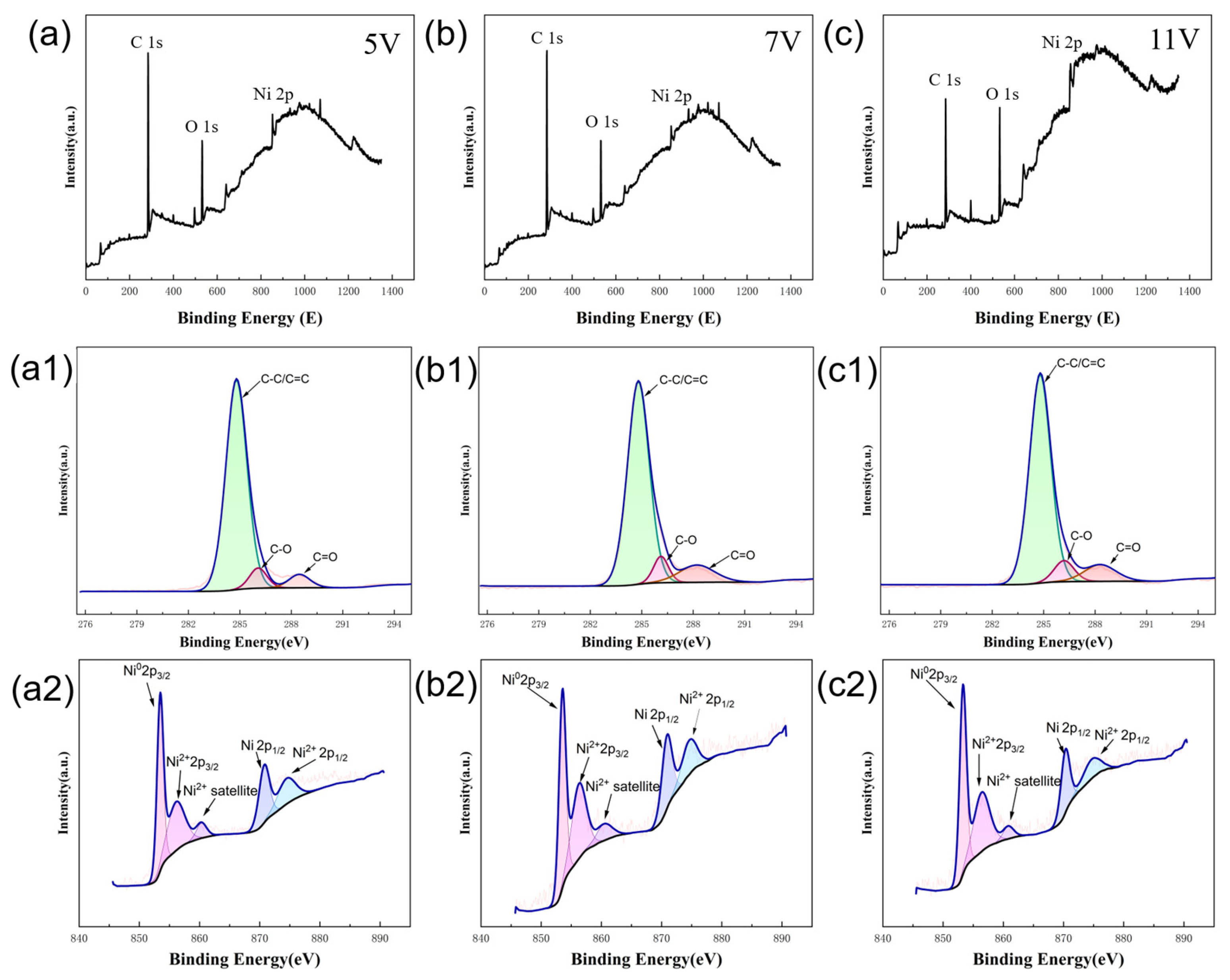
Figure 7 shows the XPS analysis results of the Ni–graphene composite coatings prepared at different deposition voltages. The survey spectra showed characteristic C 1s, O 1s, and Ni 2p peaks, indicating that graphene was successfully introduced onto the surface of the Ni-based coating. The high-resolution C 1s spectra could be deconvoluted into three components at 284.80, 286.07–286.19, and 288.22–288.47 eV, corresponding to C–C/C=C, C–O, and C=O/O–C=O, respectively. The proportions of the C–C/C=C component in the three samples were 87.1%, 81.3%, and 82.3%, indicating that surface carbon in the coatings mainly existed as graphitized sp2 carbon. The proportions of oxygen-containing carbon components were 12.9%, 18.7%, and 17.7%, respectively, indicating that the graphene sheets still contained a small amount of oxygen-containing functional groups. According to the calculated atomic percentages, the C/Ni atomic ratios of the 5, 7, and 11 V samples were 80.3, 35.4, and 56.8, respectively. The 7 V sample exhibited the highest Ni atomic percentage of 2.75 at.%, suggesting a higher exposure of the Ni signal and a more coordinated balance between graphene coverage and Ni deposition at this voltage. In the high-resolution Ni 2p spectra, the peaks at 853.29–853.52 eV and 856.27–856.60 eV corresponded to NiO and Ni(OH)2 species, respectively, and the peak at 860.48–860.84 eV was assigned to the Ni2+ satellite peak. The Ni(OH)2/[NiO + Ni(OH)2] peak-area ratios of the 5, 7, and 11 V samples were 45.2%, 44.9%, and 43.5%, respectively, indicating that the coating surfaces contained a certain amount of oxidized or hydroxylated Ni species under different deposition voltages. The combined C 1s and Ni 2p analyses indicate that a stable composite interface was formed between graphene and the Ni-based coating. Among the samples, the 7 V sample exhibited relatively high Ni exposure and an appropriate degree of graphene coverage, which favored the formation of a more uniform Ni–graphene composite coating. Previous studies have shown that an appropriate amount of oxygen-containing functional groups can adsorb or coordinate with Ni2+, thereby increasing the probability of Ni capture and nucleation on graphene surfaces and promoting stable retention of graphene sheets in the growing Ni matrix [26,35,36,37].
Figure 7.
XPS results of Ni–Gr composite coatings: survey spectra (a–c), high-resolution C 1s spectra (a1–c1), and high-resolution Ni 2p spectra (a2–c2) of the 5, 7, and 11 V samples.
3.4. Microhardness and Friction-Wear Behavior
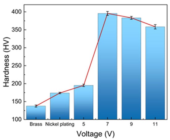
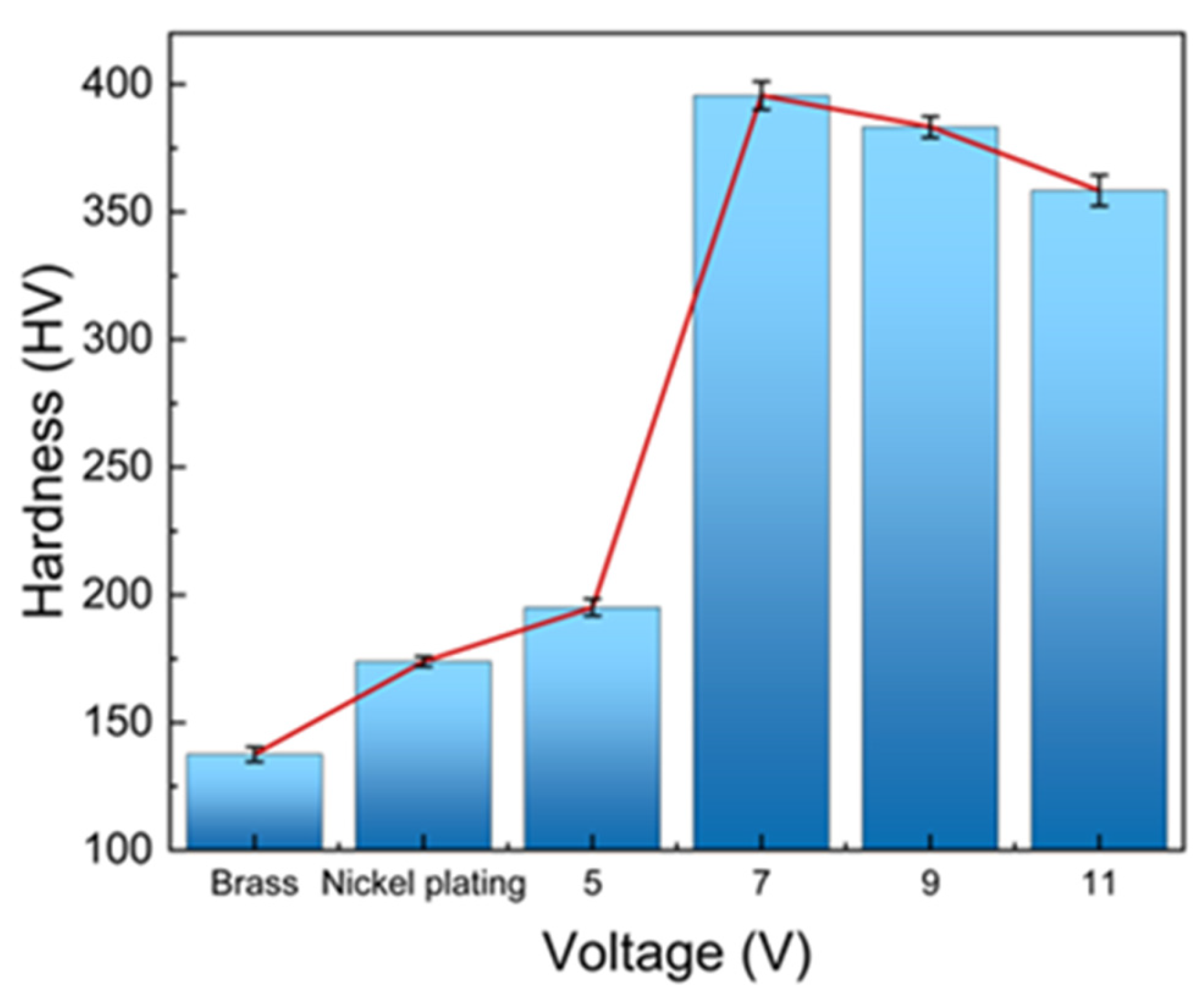
Figure 8 shows the microhardness of the brass substrate, pure Ni coating, and Ni–Gr composite coatings prepared at different working voltages. With increasing working voltage, the coating hardness first increased and then decreased. The hardness values of the 5, 7, 9, and 11 V samples were 195, 395, 383, and 358 HV, respectively, with the 7 V sample exhibiting the highest hardness. At 5 V, the driving force for Ni2+ reduction was insufficient, the coating thickness was only 6.667 μm, the microstructure was locally discontinuous, and lamellar structures suspected to be insufficiently covered by Ni were present. As a result, the dispersion-strengthening and load-transfer effects of graphene could not be fully utilized. In addition, the relatively thin coating made the microhardness measurement more susceptible to the influence of the brass substrate, resulting in a lower apparent hardness. When the working voltage increased to 7 V, the coating microstructure became denser, and the graphene dispersion and embedding state improved, which hindered dislocation motion and improved interfacial load-transfer efficiency, thus significantly increasing hardness. Scherrer analysis showed that the average domain sizes of the 5 and 7 V samples were 21.07 and 20.82 nm, respectively, with only a small difference. Therefore, the substantial hardness increase of the 7 V sample cannot be mainly attributed to grain-refinement strengthening, but should instead be attributed to the synergistic effects of coating densification, graphene dispersion strengthening, and interfacial load transfer. When the voltage further increased to 9 and 11 V, domain coarsening, graphene agglomeration, and increases in pores and coarse nodules reduced the effective load-bearing area and strengthening efficiency, resulting in a gradual decrease in coating hardness.
Figure 8.
Vickers microhardness of the brass substrate, pure Ni coating, and Ni–Gr composite coatings prepared at different working voltages.
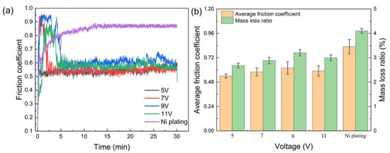
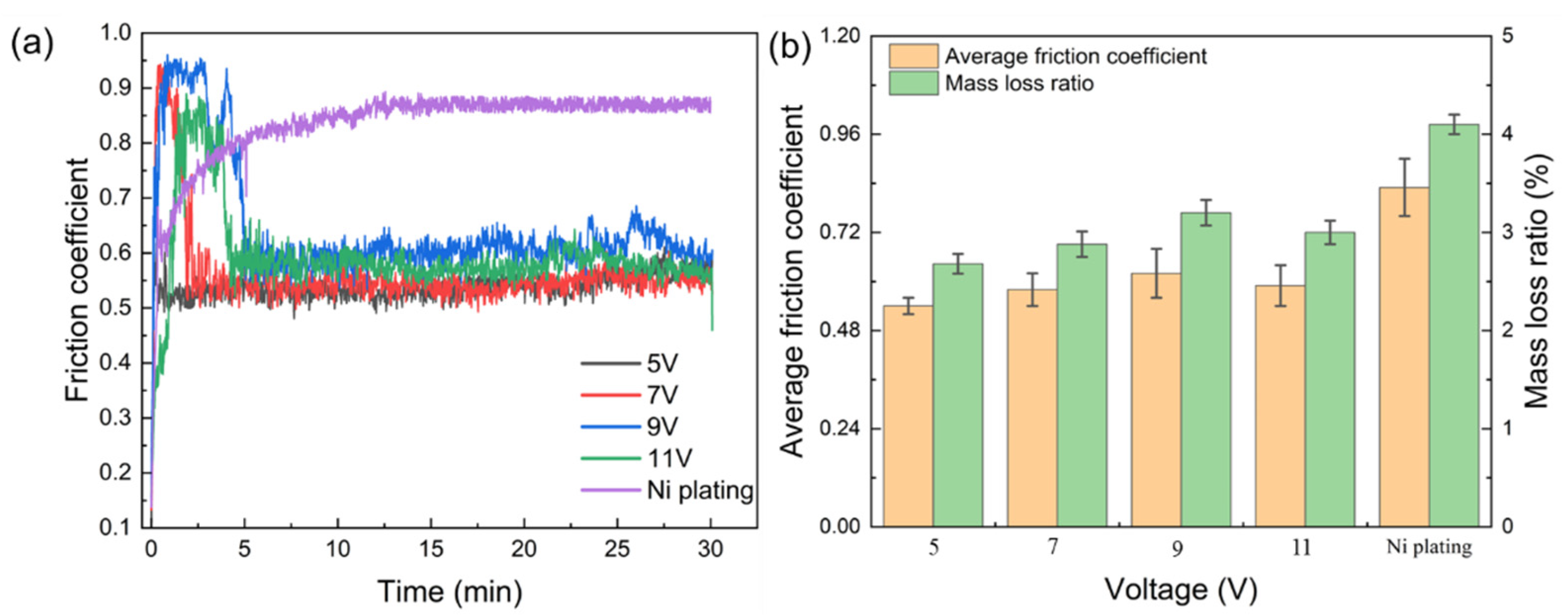
Figure 9 shows the variation in the friction coefficient with time, as well as the average friction coefficient and mass-loss ratio. The average friction coefficients of the 5, 7, 9, and 11 V samples were 0.55, 0.58, 0.62, and 0.59, respectively, and the corresponding mass-loss ratios were 2.7%, 3.0%, 3.3%, and 3.2%. Although the 5 V sample exhibited a slightly lower average friction coefficient, its coating was thinner and had lower hardness, resulting in limited resistance to ploughing and plastic deformation. The 7 V sample combined high hardness, a dense microstructure, and relatively uniform graphene distribution; therefore, the wear-track damage was relatively slight, and the coating exhibited better overall wear resistance. In the 9 and 11 V samples, graphene agglomeration and surface coarsening weakened the formation of a continuous lubricating film. Agglomerates or coarse nodules were prone to detachment during sliding and could act as abrasive particles, thereby aggravating abrasive wear and local material spalling.
Figure 9.
Friction and wear behavior of Ni–Gr composite coatings: (a) variation in friction coefficient with time; (b) average friction coefficient and mass-loss ratio.
3.5. Corrosion Resistance
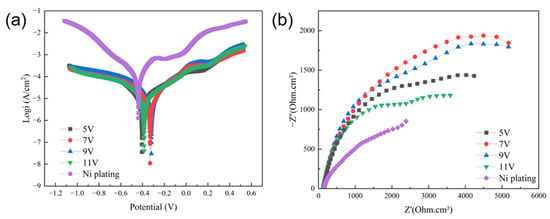
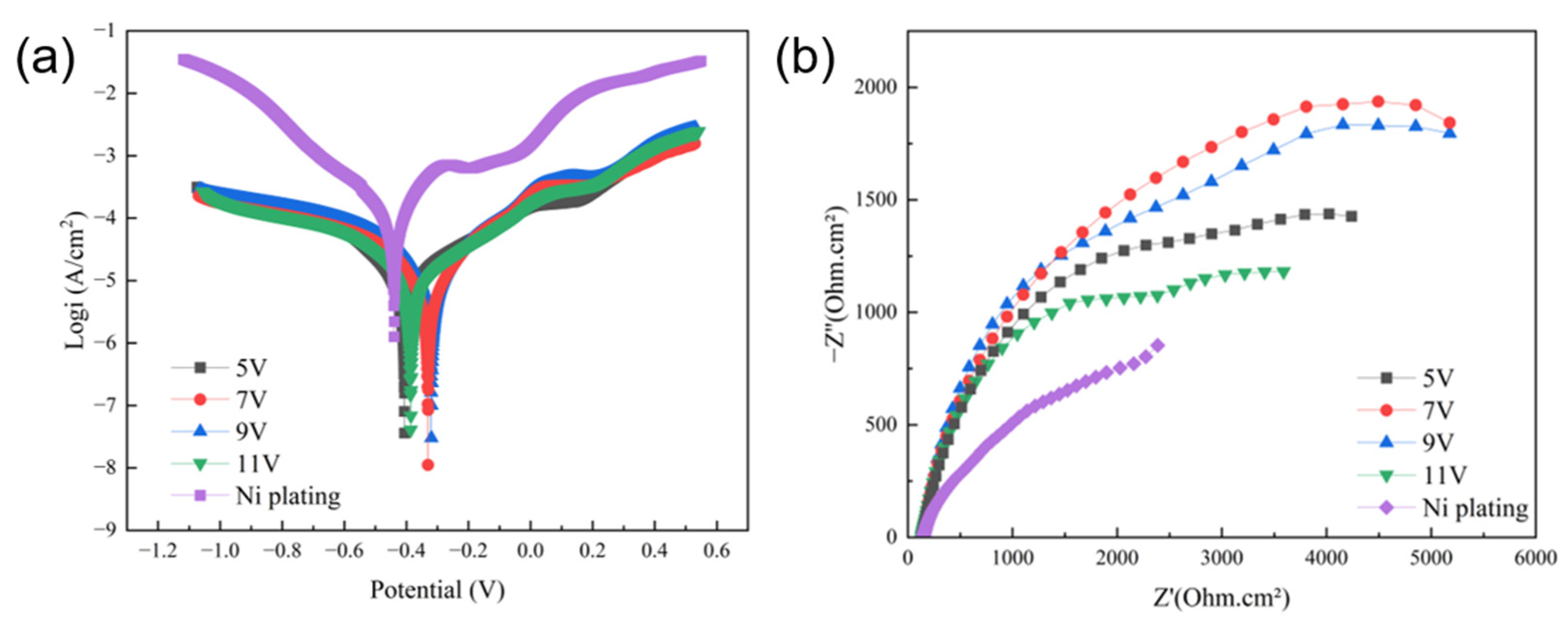
Figure 10 shows the Tafel polarization curves and Nyquist plots of different samples in 3.5 wt.% NaCl solution. The self-corrosion potential and corrosion current density of the Ni–Gr coatings prepared at different working voltages are summarized in Table 4. The corrosion current densities of the 5, 7, 9, and 11 V samples were 3.0808 × 10⁻⁵, 1.0143 × 10⁻⁵, 1.7025 × 10⁻⁵, and 3.1622 × 10⁻⁵ A/cm2, respectively. The 7 V sample exhibited the lowest corrosion current density, indicating the lowest corrosion reaction rate. In the EIS results, the 7 V sample showed the largest capacitive arc radius, demonstrating higher charge-transfer resistance and stronger corrosion-inhibition capability. Its excellent corrosion resistance mainly originated from the dense Ni matrix, fewer through-pores, and the barrier effect of uniformly dispersed graphene sheets. Graphene can extend the diffusion path of Cl− and dissolved oxygen toward the substrate, thereby reducing the penetration rate of corrosive media. Conversely, pores, pinholes, and agglomeration defects generated at 9 and 11 V provide rapid diffusion channels for corrosive media, leading to decreased corrosion resistance.
Figure 10.
Electrochemical corrosion behavior of Ni–Gr composite coatings prepared at different working voltages in 3.5 wt.% NaCl solution: (a) Tafel polarization curves; (b) Nyquist plots.
Table 4.
Self-corrosion potential and corrosion current density of Ni–Gr coatings at different voltages.
3.6. Thermal Conductivity
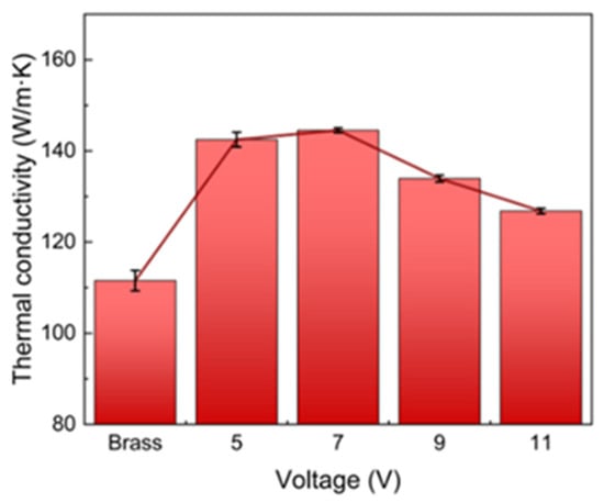
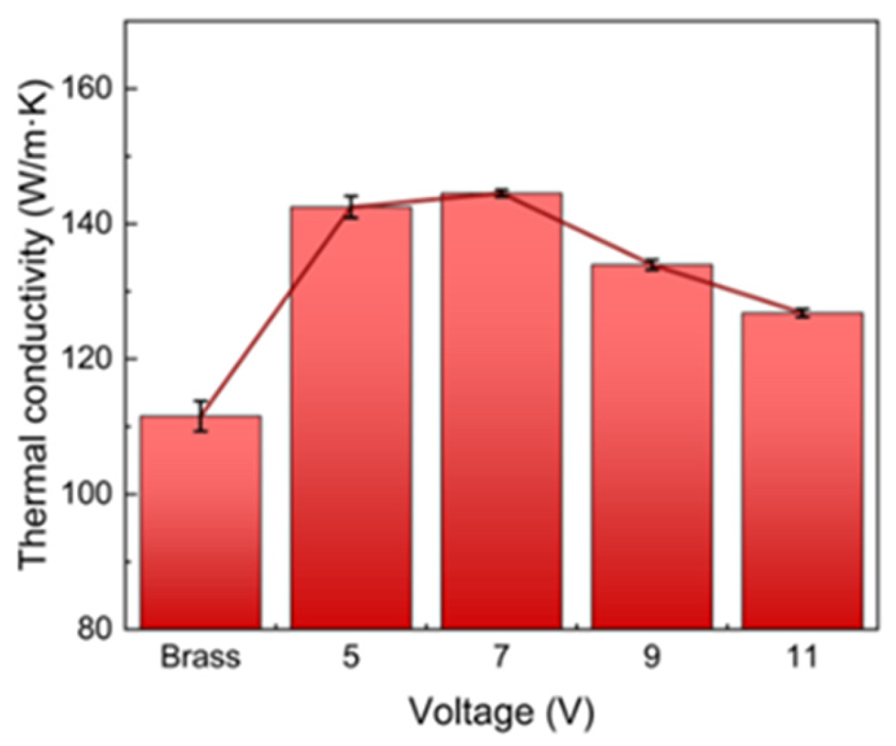
Figure 11 shows the room-temperature thermal conductivity of the brass substrate and Ni–Gr coating/brass composite specimens prepared at different voltages. The thermal conductivity of the specimens also first increased and then decreased with increasing working voltage. At 5 V, the thermal conductivity was 142 W/(m·K); at 7 V, it increased to 145 W/(m·K), which was 29.5% higher than that of the brass substrate measured in this work. At 9 and 11 V, the thermal conductivity decreased to 134 and 127 W/(m·K), respectively. Under the 7 V condition, the coating had high compactness and relatively uniform graphene dispersion, which favored the formation of local thermal-conduction pathways and reduced interfacial thermal resistance. At higher voltages, graphene agglomeration, increased porosity, and microstructural discontinuity disrupted heat-flow transfer pathways and increased phonon/electron scattering and interfacial thermal resistance, leading to decreased thermal conductivity. These results indicate that thermal conductivity is determined not only by graphene content but also by its dispersion state, coating compactness, and interfacial continuity.
Figure 11.
Room-temperature thermal conductivities of the brass substrate and Ni–Gr composite coatings prepared at different working voltages.
4. Conclusions
Ni–graphene (Ni–Gr) composite coatings were successfully fabricated on brass substrates by electro-brush plating, and the effects of working voltage on their microstructure, graphene incorporation, and multifunctional performance were systematically investigated. The main conclusions are as follows:
(1) Working voltage played a critical role in regulating the deposition behavior and surface quality of the Ni–Gr composite coatings. Increasing the voltage from 5 to 11 V increased the coating thickness from 6.667 to 19.334 μm. However, excessive voltage accelerated Ni deposition and intensified side reactions, leading to surface coarsening, pore/pinhole formation, and nonuniform graphene distribution. Among the investigated conditions, the coating prepared at 7 V exhibited the most compact and uniform microstructure, with a thickness of 8.524 μm and the lowest Raman ID/IG ratio of 1.2146.
(2) The Ni–Gr coating prepared at 7 V showed the best overall performance. Its microhardness reached 395 HV, which was approximately 190% and 127% higher than those of the brass substrate and pure Ni coating, respectively. In 3.5 wt.% NaCl solution, the corrosion current density decreased to 1.0143 × 10⁻⁵ A/cm2, corresponding to a 90.4% reduction compared with the pure Ni coating. The room-temperature thermal conductivity of the coating/brass composite specimen reached 145 W/(m·K), which was 29.5% higher than that of the brass substrate.
(3) The enhanced comprehensive performance at 7 V was mainly attributed to the synergistic effect of moderate cathodic polarization, compact Ni matrix formation, and relatively uniform graphene incorporation. The dense coating structure improved corrosion protection, while the embedded graphene contributed to load transfer, solid lubrication, and local heat-transfer pathways. In contrast, excessive voltages of 9 and 11 V caused graphene agglomeration and structural defects, weakening the reinforcing, barrier, lubricating, and thermal-conductive effects.
(4) These findings demonstrate that working voltage is a key processing parameter for tailoring the microstructure and multifunctional properties of electro-brush-plated Ni–Gr composite coatings. An optimized voltage of 7 V provides an effective route for improving the surface durability and heat-transfer performance of brass heat-dissipation components.
Author Contributions
Conceptualization, Z.Z.; Methodology, Z.Z. and H.W.; Validation, Z.Z., H.W., W.M. and Y.M.; Formal analysis, H.W.; Investigation, H.W., W.M. and Y.M.; Resources, H.W., W.M. and Y.M.; Data curation, H.W.; Writing – original draft, H.W.; Writing – review & editing, Z.Z. and H.W.; Supervision, Z.Z., W.M. and Y.M.; Project administration, Z.Z.; Funding acquisition, Z.Z. All authors have read and agreed to the published version of the manuscript.
Funding
This study was financially supported by Special Project of Local Science and Technology Development Guided by the Central Government of China (24ZYQA035), Gansu Province Key R&D Plan Industrial Projects (24YFGC001), Scientific Research Project of Lanzhou Science and Technology Bureau (2023-1-23).
Data Availability Statement
Data are contained within the article.
Conflicts of Interest
The authors declare no conflict of interest.
References
- Zhang, C.; Yuan, T.; Wang, Y.; Guo, H.; Lan, F.; Chang, B.; Huang, L.; Li, Z. A novel heat dissipation structure for temperature uniformity and thermal lifetime enhancement in film capacitors. J. Energy Storage 2026, 144, 119684. [Google Scholar] [CrossRef] [Scilit]
- Jebelli, A.; Lotfi, N.; Zare, M.S.; Yagoub, M.C.E. Advanced thermal management for high-power ICs: Optimizing heatsink and airflow design. Appl. Sci. 2024, 14, 9406. [Google Scholar] [CrossRef] [Scilit]
- Resen, I.S.; Skheel, O.R.; Alkhafaji, M.H.; Ali, B. An experimental study for enhancing heat transfer in a minichannel heat sink by an innovative configuration. Int. J. Therm. Sci. 2026, 220, 110397. [Google Scholar] [CrossRef] [Scilit]
- Jiang, F.; Wang, H.; Hu, Y.; Ling, X.; Zhang, T. Charging/discharging performance and corrosion behavior of a novel latent heat thermal energy storage device with different fin plate materials. Renew. Energy 2024, 220, 119584. [Google Scholar] [CrossRef] [Scilit]
- Yu, Z.-Q.; Li, M.-T.; Cao, B.-Y. A comprehensive review on microchannel heat sinks for electronics cooling. Int. J. Extrem. Manuf. 2024, 6, 133–162. [Google Scholar] [CrossRef] [Scilit]
- Ainali, M.; Beal, R.E.; Sundberg, R.; Wickman, L. Corrosion of copper/brass radiators—Corrosion mechanisms—Prevention actions. SAE Tech. Pap. 1992, 920180. [Google Scholar] [CrossRef] [Scilit]
- Romaine, A.; Crozet, M.; Mary, N.; Normand, B.; Chassagne, M.; Dufour, F. Importance of the surface and environmental conditions on the corrosion behavior of brass, steel and brass coated steel wires and brass coated steel cords. Corros. Sci. 2020, 177, 108966. [Google Scholar] [CrossRef] [Scilit]
- Swamy, K.S. Study on thermal resistance of brass with and without coating of metallic surface. Mater. Today Proc. 2021, 35, 335–339. [Google Scholar] [CrossRef] [Scilit]
- Ren, W.; Wang, P.; Fu, Y.; Pan, C.; Song, J. Effects of temperature on fretting corrosion behaviors of gold-plated copper alloy electrical contacts. Tribol. Int. 2015, 83, 1–11. [Google Scholar] [CrossRef] [Scilit]
- Sun, H.; Song, B.; Sun, X.; Cui, X.; Liu, Z.; Cong, M.; Sun, M.; Zhu, Z.; Tian, Y.; Liu, S.; et al. Recent representative progress of surface coating technology. Chem. Rec. 2025, 25, e202500054. [Google Scholar] [CrossRef] [Scilit] [PubMed]
- Ma, C. Coating technology makes comprehensive surface protection possible. Coatings 2023, 13, 658. [Google Scholar] [CrossRef] [Scilit]
- Rane, K.K.; Zare, M.; Toma, F.; Behera, S.K.; Church, B.; Rohatgi, P. Surface alloying and surface compositing of copper alloy castings using mold and core coatings. Int. J. Met. 2026. [Google Scholar] [CrossRef] [Scilit]
- Wang, H.; Chen, S.; Xiang, Y. Study on repairing technologies and repairing experiment by electro-brush plating of camshaft. IOP Conf. Ser. Mater. Sci. Eng. 2018, 439, 022010. [Google Scholar] [CrossRef] [Scilit]
- Wang, F.; Zhang, H.; Liao, Y.; Xu, R.; Zhang, H. Development status of surface treatment technology for copper and its alloys for metallurgical equipment. Chin. J. Eng. 2024, 46, 470–479. [Google Scholar] [CrossRef]
- Liu, H.; Li, Z.; Wang, J.; Sheng, C.; Liu, W. Wear resistance properties reinforcement using nano-Al/Cu composite coating in sliding bearing maintenance. J. Nanosci. Nanotechnol. 2018, 18, 2152–2157. [Google Scholar] [CrossRef] [Scilit] [PubMed]
- Sajjadnejad, M.; Haghshenas, S.M.S.; Badr, P.; Setoudeh, N.; Hosseinpour, S. Wear and tribological characterization of nickel matrix electrodeposited composites: A review. Wear 2021, 486–487, 204098. [Google Scholar] [CrossRef] [Scilit]
- Gurtaran, M.; Zhang, Z.; Li, X.; Dong, H. Characterisation of electro-brush plated nickel coatings on P-type (Zr,Ti)Co(Sn,Sb) half-Heusler thermoelectric materials for stable contact layers. Materials 2025, 18, 5108. [Google Scholar] [CrossRef] [Scilit] [PubMed]
- Sayer, R.A.; Zeng, J.; Hsu, H.H.; Peroulis, D.; Fisher, T.S. Thermal and electrical conductivities of nanocrystalline nickel microbridges. J. Microelectromechanical Syst. 2012, 21, 850–858. [Google Scholar] [CrossRef] [Scilit]
- Gao, M.; Pei, Z.; Gong, J.; Song, G. The improved wear resistance of Ni-based composite coatings by the synergistic effect of diamond and self-lubricating particles. Colloids Surf. A Physicochem. Eng. Asp. 2026, 730, 138983. [Google Scholar] [CrossRef] [Scilit]
- Patil, A.; Nartu, M.S.K.K.Y.; Ozdemir, F.; Banerjee, R.; Gupta, R.K.; Borkar, T. Effect of graphene morphology on the microstructure, mechanical and tribological behavior of nickel matrix composites. JOM 2022, 74, 4583–4596. [Google Scholar] [CrossRef] [Scilit]
- Zhang, D.; Cui, X.; Jin, G.; Zhang, X. Improvement in microstructure uniformity and mechanical properties of surface modified graphene reinforced Ni-based composites by laser deposition. J. Alloys Compd. 2021, 887, 161305. [Google Scholar] [CrossRef] [Scilit]
- Xu, P.; Shen, X.; Xin, G. Electro-brush plating Ni–graphene oxide composite coating enhanced corrosion resistance of fluoride ion. Mater. Res. Express 2021, 8, 026406. [Google Scholar] [CrossRef] [Scilit]
- Zhang, D.; Cui, X.; Jin, G.; Li, D.; Fang, Y.; Wen, X.; Ma, G.; Wang, H.; Xu, B. Comparison of MWCNTs and GO reinforced electro-brush plated Ni nanocomposite coatings: Structural variations of carbon-based reinforcements and tribological behavior. J. Alloys Compd. 2020, 832, 154941. [Google Scholar] [CrossRef] [Scilit]
- Qi, S.; Li, X.; Dong, H. Reduced friction and wear of electro-brush plated nickel composite coatings reinforced by graphene oxide. Wear 2019, 426–427, 228–238. [Google Scholar] [CrossRef] [Scilit]
- Jagannadham, K. Thermal conductivity of copper-graphene composite films synthesized by electrochemical deposition with exfoliated graphene platelets. Metall. Mater. Trans. B 2012, 43, 316–324. [Google Scholar] [CrossRef] [Scilit]
- Yang, L.; Zhu, Y.; Liu, H.; Guo, T.; Tang, H.; Ya, S.; Li, Y.; Wang, H.; Luo, Y.; Ma, J.; et al. Co-deposition and thermal conductivity of nickel-graphene composite coatings on copper surface. Appl. Phys. A 2023, 129, 757. [Google Scholar] [CrossRef] [Scilit]
- Muniz, F.T.L.; Miranda, M.A.R.; Dos Santos, C.M.; Sasaki, J.M. The Scherrer equation and the dynamical theory of X-ray diffraction. Acta Crystallogr. Sect. A 2016, 72, 385–390. [Google Scholar] [CrossRef] [Scilit] [PubMed]
- Qin, B.; Ma, L.; Wang, S.; Hou, C.; Zhou, S. Construction of a sandwich-like Gr/Ni composite coating on AZ91D magnesium alloy to achieve excellent corrosion and wear resistances in the seawater. Diam. Relat. Mater. 2022, 130, 109400. [Google Scholar] [CrossRef] [Scilit]
- Boukhouiete, A.; Boumendjel, S.; Sobhi, N.E.H. Effect of current density on the microstructure and morphology of the electrodeposited nickel coatings. Turk. J. Chem. 2021, 45, 1599–1608. [Google Scholar] [CrossRef] [Scilit] [PubMed]
- Yang, F.; Tian, W.; Nakano, H.; Tsuji, H.; Oue, S.; Fukushima, H. Effect of Current Density and Organic Additives on the Texture and Hardness of Ni Electrodeposited from Sulfamate and Watt’s Solutions. Mater. Trans. 2010, 51, 948–956. [Google Scholar] [CrossRef] [Scilit]
- Ji, R.; Jin, H.; Liu, Y.; Dong, T.; Zhang, F.; Zhao, L.; Wu, X.; Sun, Q.; Liu, P.; Dong, H.; et al. Efficient preparation of nanoparticle-reinforced nickel-based composite coating with highly preferred (220) orientation. Chin. J. Mech. Eng. 2020, 33, 91. [Google Scholar] [CrossRef] [Scilit]
- Liu, M.; Liu, H.; Wang, D.; Liu, B.; Shi, Y.; Li, F.; Gong, Y.; Li, L.; Li, L.; Zhang, W. Effect of Nanodiamond Concentration and the Current Density of the Electrolyte on the Texture and Mechanical Properties of Ni/Nanodiamond Composite Coatings Produced by Electrodeposition. Materials 2019, 12, 1105. [Google Scholar] [CrossRef] [Scilit] [PubMed]
- Li, Y.; Lei, W.; Li, Z.; Qian, H.; Fang, C.; He, B. Research on the Electrodeposition of Graphene Quantum Dots under Supercritical Conditions to Enhance Nickel-Based Composite Coatings. Metals 2023, 13, 1794. [Google Scholar] [CrossRef] [Scilit]
- Xia, Y.; Zuo, Q.; Sun, C.; Hu, G.; Fang, B. Hierarchically Electrodeposited Nickel/Graphene Coatings for Improved Corrosion Resistance of Ni Foam Flow Field in PEMFC. Inorganics 2024, 12, 293. [Google Scholar] [CrossRef] [Scilit]
- Ioni, Y.; Popova, A.; Maksimov, S.; Kozerozhets, I. Ni Nanoparticles on the Reduced Graphene Oxide Surface Synthesized in Supercritical Isopropanol. Nanomaterials 2023, 13, 2923. [Google Scholar] [CrossRef] [Scilit] [PubMed]
- Lee, D.W.; De Los Santos, V.L.; Seo, J.W.; Felix, L.L.; Bustamante D., A.; Cole, J.M.; Barnes, C.H.W. The structure of graphite oxide: Investigation of its surface chemical groups. J. Phys. Chem. B 2010, 114, 5723–5728. [Google Scholar] [CrossRef] [Scilit] [PubMed]
- Ganguly, A.; Sharma, S.; Papakonstantinou, P.; Hamilton, J. Probing the thermal deoxygenation of graphene oxide using high-resolution in situ X-ray-based spectroscopies. J. Phys. Chem. C 2011, 115, 17009–17019. [Google Scholar] [CrossRef] [Scilit]

Disclaimer/Publisher’s Note: The statements, opinions and data contained in all publications are solely those of the individual author(s) and contributor(s) and not of MDPI and/or the editor(s). MDPI and/or the editor(s) disclaim responsibility for any injury to people or property resulting from any ideas, methods, instructions or products referred to in the content. |
© 2026 by the authors. Licensee MDPI, Basel, Switzerland. This article is an open access article distributed under the terms and conditions of the Creative Commons Attribution (CC BY) license.