


Abstract
Pulsar detection holds significant value in spacecraft autonomous navigation, space-based time reference establishment, and space science research. The X-ray telescope is a crucial instrument for pulsar detection, and its focusing mirror—the most critical component—exhibits detection performance directly influenced by the film thickness uniformity. This paper proposes an off-axis biaxial rotation coating method and derives, for the first time, a theoretical model of film thickness distribution on a cylindrical substrate based on classical thin-film deposition theory. Using this model, we systematically analyze the influence of key coating parameters—namely the distances a and b from the evaporation source to the vertical rotation axis and to the horizontal rotation axis, respectively—on thickness uniformity. By optimizing the coating process parameters, the thickness uniformity on the cylindrical substrate is significantly improved. When parameters a and b are within certain ranges and satisfy a specific relationship, a film with thickness uniformity better than 1% can be obtained. Coating experiments are carried out on a mandrel cylinder, and the measured film thickness distribution shows good agreement with theoretical predictions, with a maximum deviation of only 1.2%, thereby validating the accuracy of the proposed model. This work provides a rapid, non-iterative approach for determining coating parameters, significantly improving efficiency and reducing costs.
1. Introduction
Pulsar navigation holds paramount importance in the field of deep-space exploration [1,2]. By precisely detecting X-ray pulse signals emitted from pulsars—rapidly rotating neutron stars—highly stable time and position reference signals can be acquired. X-ray pulsar navigation represents an astronomical autonomous navigation method, offering advantages including strong autonomy, high security, exceptional reliability, and non-cumulative navigation errors [3,4,5,6]. Compared to traditional satellite navigation systems, pulsar navigation achieves global coverage (encompassing near-Earth, deep-space, and interstellar domains) without error accumulation over time or distance, establishing itself as the sole solution for ultra-long-range autonomous navigation [7,8]. Currently, the primary instrument for pulsar detection is the focusing X-ray telescope, in which the focusing optical system is the most crucial component [9]. This system operates based on the grazing incidence total reflection principle of X-rays, utilizing concentrically stacked parabolic mirrors to focus X-rays onto a single focal point, thereby enabling high-precision detection [10,11,12]. Due to the extremely weak X-ray signals from pulsars, even minor surface imperfections or deformations in the mirrors of the optical system can degrade the focusing performance and reduce the detection sensitivity of the telescope [13,14,15]. Therefore, the development of high-quality mirrors is essential for high-performance X-ray detection. On the foundation of an excellent mirror substrate, the deposition of a highly uniform reflective film is the key to realizing such high-quality mirrors.
To improve coating thickness uniformity, researchers worldwide have conducted extensive studies, with the most widely adopted method being the planetary rotation system [16,17,18,19]. This system controls the eccentric rotation and self-revolution of the coated workpiece. Within such systems, film uniformity is governed by factors including evaporation source type, target geometry, relative positioning between target and substrate, and motion dynamics [18,19]. In 1973, to achieve a coating with uniform film thickness distribution (FTD) on the substrate, scientists proposed a planetary rotation system [20]. This system controls the coating substrate to rotate simultaneously on its own axis and around another axis. They also analyzed and compared the differences in FTD between biaxial rotation and single-axis rotation. With the advancement of coating technology, researchers have conducted studies on the FTD across substrates of various shapes, such as spherical and conical surfaces [21,22,23,24,25]. Furthermore, the coating uniformity of cylindrical or near-cylindrical substrates has also attracted extensive attention. Zhang et al. [26] established a mathematical model for thermal spray coating thickness on cylindrical surfaces and systematically investigated the effects of scanning angle and radius of curvature on the uniformity. Wang et al., focusing on pipeline weld repair processes, employed computational fluid dynamics and response surface methodology to analyze the influence of spray distance and traverse speed on the coating thickness distribution [27]. In the physical vapour deposition field, Hass et al. achieved non-line-of-sight deposition on stationary non-rotating cylindrical fiber substrates using a rarefied gas jet [28]. Cui et al. and Loffler et al. investigated the coating uniformity of RF sputtering and DC sputtering, respectively, on the inner walls of slender cylindrical pipes [29,30]. Tahir et al. analyzed the uniformity of liquid film coating on a rotating cylindrical surface based on lubrication theory [31]. Huang et al. developed an FTD model for roll-to-roll flexible substrate sputtering [32]. However, the aforementioned studies mostly focus on simple motion patterns where the substrate rotates around a single axis, or are primarily oriented toward inner surface coating. The FTD theory for the outer surfaces of mandrel-type cylinders under off-axis biaxial rotation has not yet been sufficiently explored.
Compared to traditional mirrors like flat or spherical ones, X-ray telescopes have a unique structure: they are a body of revolution with a parabolic cross-section, closely resembling a cylinder [11]. Currently, the primary manufacturing method for X-ray telescopes is the electroformed nickel replication technique [33,34,35,36]. This method produces high-quality mirrors by precisely replicating the lateral profile of a master mandrel cylinder. A paramount step in the electroformed nickel replication method is the deposition of a coating with highly uniform thickness onto the cylindrical mandrel. The success of this specific step is critical, as it directly governs the ultimate quality of the replicated mirror. Based on the foregoing analysis, while there is a substantial body of research on coating thickness uniformity for flat, spherical, and conical substrates, and certain explorations have also been undertaken on cylindrical and tubular substrate coatings, existing studies have not yet established a theoretical model for the FTD applicable to the lateral surface of a mandrel cylinder under off-axis biaxial rotation.
This study investigates the coating process and FTD for X-ray telescope mirrors. We implement a biaxial rotation method (simultaneous rotation about horizontal and vertical axes) with an off-axis evaporation source, significantly enhancing side surface uniformity. To analyze the FTD on the cylindrical side-surface, the paraboloid-shaped mandrel is approximated as a cylinder in this study. Based on classical FTD theory, a theoretical model for coating FTD on the cylindrical surface was developed, identifying key factors influencing uniformity. Coating parameters were subsequently optimized to enhance thickness uniformity.
2. Theoretical Analysis of Film Thickness Distribution
2.1. Off-Axis Biaxial Rotation Coating Method
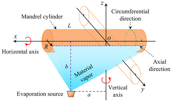
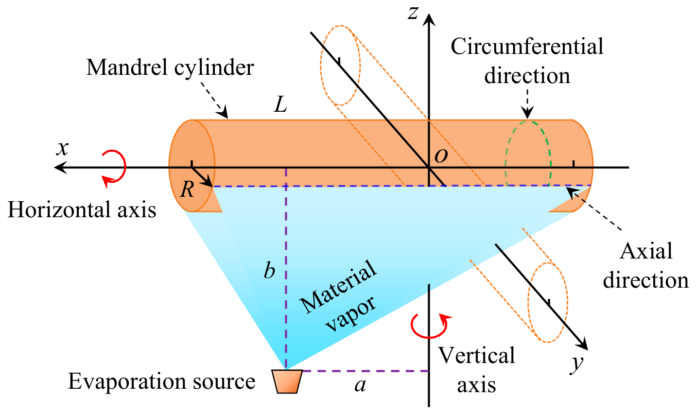
Figure 1 shows the schematic diagram of the off-axis biaxial rotation coating scheme. The system primarily consists of a cylindrical substrate and an evaporation source. The substrate is a cylinder of length L and radius R, with its axis aligned with the x-axis. The coordinate system has the y- and z-axes intersecting the x-axis at the origin O, with the z-axis oriented vertically. The evaporation source is positioned below and offset from the cylinder, located at distances b from the x-axis and a from the z-axis.
Figure 1.
Schematic of the off-axis biaxial rotation coating system.
During the evaporation coating process, the evaporation source emits coating material vapor upward, depositing onto the lateral surface of the cylindrical substrate. Simultaneously, the cylinder rotates about both the horizontal rotation axis (x-axis) and the vertical rotation axis (z-axis). When the cylinder rotates solely about the x-axis, this motion improves thickness uniformity along the circumferential direction (indicated by dashed ellipse). Under this single-axis rotation, the FTD is uniform within any individual circumferential direction path. However, thickness variations exist between different circumferential direction paths, correlating with their respective distances from the evaporation source. When both axes rotate concurrently, the biaxial motion further enhances thickness uniformity along the axial direction (denoted by dashed lines), thereby improving the overall thickness uniformity across the entire surface of the cylinder.
2.2. Theoretical Model of Film Thickness Distribution
2.2.1. Thickness Distribution Model for Stationary Cylinder
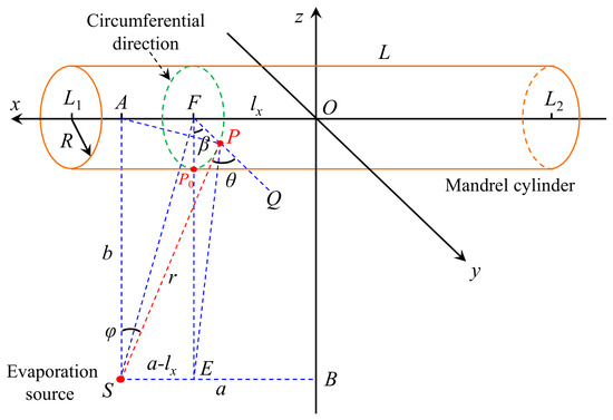
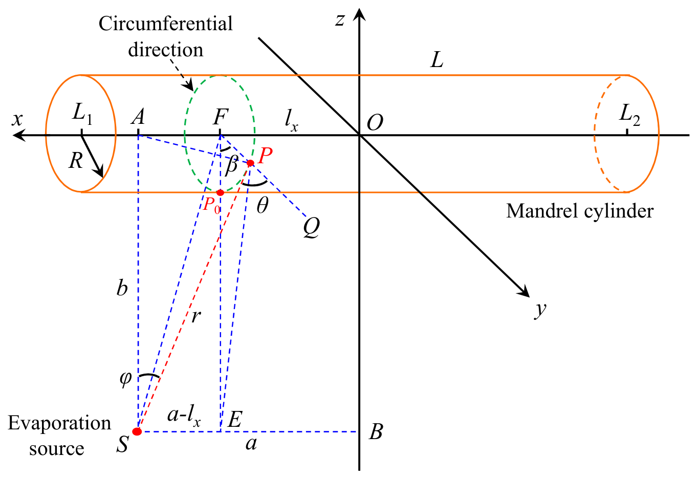
The geometric model shown in Figure 2 is constructed according to Figure 1. The O-yz plane bisects the cylinder into asymmetric segments of lengths L1 (positive x-axis) and L2 (negative x-axis). The evaporation source S projects orthogonally to points A (x-axis) and B (z-axis). Point F (center of a circumferential path) is offset by lx from origin O, with its projection E on line SB satisfying |SE| = a-lx. An arbitrary point P on the path lies at a distance r from S, while the minimal-distance point P0 (circumferential nadir) resides on line FE. Critical geometric definitions:
Figure 2.
Geometric model of the stationary cylindrical substrate. (The black coordinate system corresponds to the stationary state of the cylinder).
Source normal: SA;
Vapor direction: SP;
Emission angle: φ = ∠ASP;
Surface element normal: FP (extended to Q);
Incident angle: θ = ∠SPQ (between surface normal and vapor direction).
During deposition, surface element P undergoes continuous rotation about F, with rotation angle ∠P0FP = β measured from rotational origin P0.
In practical coating equipment, the evaporation source is typically a hemispherical tungsten evaporation boat with a diameter of 15 mm. In constructing the theoretical model, the evaporation source is assumed to be a finite-area source. Due to the finite area of evaporation source S, its vapor emission density follows a cosine distribution law, where the emission density is proportional to the cosine of the emission angle φ. Given the total coating material mass m and density ρ, the FTD on the cylindrical lateral surface is derived from classical coating theory [37] as t:
By solving for the unknown parameters in the above equations, the FTD on the stationary cylindrical substrate can be determined.
As illustrated in Figure 2, within triangles △FEP, △PES, △FES, △FPS, △AFP, and △PSA, angles ∠PES, ∠FES, and ∠AFP constitute right angles at vertices E, E, and F, respectively. Through systematic application of the cosine theorem and related geometric principles, the following system of equations is established:
Solving the above equation system yields:
According to the preceding equations, when the cylindrical substrate remains stationary and a specific circumferential path is fixed, parameters a, b, and lx remain constant, while variables r, cosθ, and cosφ are solely determined by angle β. Furthermore, deposition occurs exclusively within regions where the incident angle θ < 90° under stationary conditions. Assuming that the coating angle β corresponding to θmax = 90° is βmax, according to Formula (3), we can obtain:
Based on the foregoing analysis, the FTD ts for the stationary cylindrical substrate can be determined as:
In this expression, the deposition-permissible angle β ranges from −βmax to βmax (−βmax < β < βmax).
To intuitively represent the relative thickness distribution (RTD) of the stationary cylindrical substrate, the maximum film thickness serves as the reference value, with thickness variations relative to this benchmark characterizing the RTD. Defining ts-max as the maximum thickness under stationary conditions, the RTD can be expressed as:
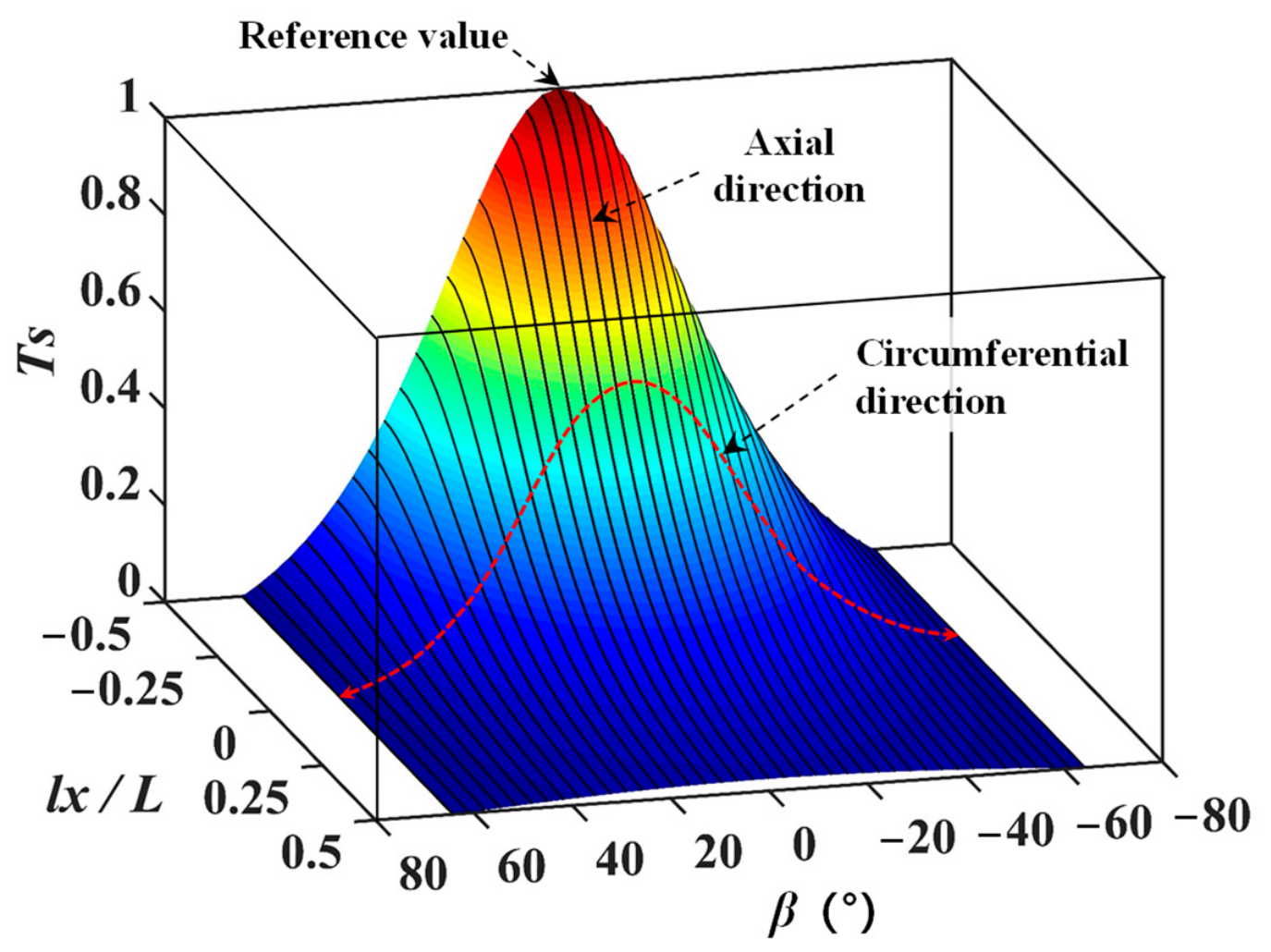
For the exemplary cylinder with radius R = 100 mm and length L = 300 mm, the vertical rotation axis passes through its geometric center, resulting in symmetric segmentation (L1 = L2). The evaporation source is positioned at a distance b = 2.3R = 230 mm from the x-axis and a = 0.5L = 150 mm from the z-axis, aligning its normal vector with one cylindrical end-face.
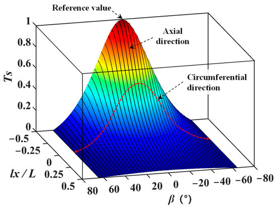
Figure 3 presents the computed RTD under stationary conditions using these parameters, where the dual horizontal axes represent the deposition-permissible angle β and normalized axial position lx/L respectively, while the ordinate indicates the RTD Ts of the film. According to the results, the highest point in the figure is the reference value, which corresponds to the leftmost endpoint at the bottom of the cylinder and is also the point closest to the evaporation source. The film thickness at the lowest point is 0, and the corresponding angle range for coating is −64.2° < β < 64.2°. It can be seen that the variation of film thickness reaches 100%. The red dashed curves characterize circumferential direction FTDs, demonstrating maximum thickness at the cylinder’s base with progressive attenuation toward both lateral edges and symmetric bilateral profiles. The black solid curve represents the FTD in the axial direction. It can be seen that as the distance from the evaporation source increases, the film thickness gradually decreases.
Figure 3.
Relative thickness distribution on the stationary cylindrical substrate. (The color of the surface corresponds to the magnitude of the relative thickness distribution).
2.2.2. Thickness Distribution Model Under Biaxial Rotation
When the cylindrical substrate rotates solely about the x-axis while neglecting fractional rotation cycles, the film thickness along any circumferential path corresponds to the circumferential average of the total deposition accumulated during stationary conditions, thereby yielding uniform FTD circumferentially. This uniform thickness is derived by integrating the stationary-state FTD over the angular domain and normalizing to the full rotation cycle.
For concurrent biaxial rotation about both axes, the FTD represents the spatial average of accumulated deposition across all horizontal angular positions during hypothetical stationary states, normalized over the entire lateral surface. The dynamic biaxial thickness profile is consequently obtained through double integration of the stationary FTD over the combined angular domains, followed by normalization across the complete substrate surface. In the biaxial rotation model, the instantaneous orientation of any point on the surface relative to the evaporation source is defined by two angles. To calculate the FTD, integration is performed over the full 0 to 2π range for both rotation angles, ensuring that every orientation is uniformly sampled without bias toward any particular direction. During the entire biaxial rotation coating process, the number of rotations can reach hundreds or even thousands (the ratio of the angular velocity of the horizontal axis and the vertical axis is not less than 5:1), and the fractional rotation cycle has little effect on the FTD (less than 0.2%), which can be almost ignored. Therefore, when building the model, it is considered that the coating time corresponding to all points on the cylinder is the same.
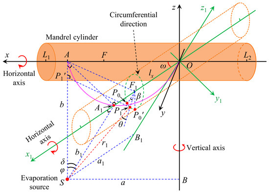
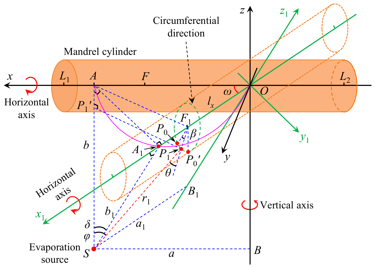
During concurrent biaxial rotation of the cylindrical substrate about both x- and z-axes, the geometric model in Figure 4 is established. Here, the coordinate system O-xyz associated with the solid cylinder represents the initial position prior to z-axis rotation. Upon horizontal rotation through angle ω, the cylindrical substrate transitions to the phantom configuration (dashed outline). This rotation alters the relative positioning between the evaporation source and the rotated cylinder, now described by the green-tagged reference frame O-x1y1z1. Consequently, the orthogonal projections of the evaporation source onto the axes evolve from points A and B to A1 and B1, with corresponding source-to-axis distances transforming from b and a to b1 and a1 respectively.
Figure 4.
Geometric model of the cylinder under simultaneous biaxial rotation. (The black coordinate system corresponds to the initial position, and the green one corresponds to the coordinate system when the cylinder rotates about the vertical axis).
Geometric analysis reveals that both △OAS and △OA1S are right-angled triangles with right angles at vertices A and A1, respectively. Consequently, points O, S, A, and A1 are coplanar on a spherical surface where line segment OS constitutes the diameter. Further derivation establishes that the intersection of the spherical surface OS with the coordinate plane O-xy traces the locus of point A1 in plane O-xy (light red curve), confirming its circular trajectory. This geometric constraint necessitates that △OA1A forms a right-angled triangle with the right angle at vertex A1. Simultaneously, since line segment AA1 lies entirely within plane O-xy, △SAA1 also satisfies right-angle conditions with the right angle at vertex A. Based on these geometric relations, the following system of equations and its solution are derived:
When the cylinder rotates through an angle ω within the horizontal plane, the center of its circular cross-section shifts from point F to F1. Consequently, the point on the circumference closest to the evaporation source is no longer located at the bottom of the cylinder, but instead lies within the O-x1z1 plane, specifically at point P0. Let the angle subtended by the arc from the starting point P0 to a circumferential point P1, denoted ∠P1F1P0, be β. The line segment SP1 represents the vapor emission direction, with a distance r1. Let ∠ASP1 be the vapor incidence angle φ, and θ be the angle between the evaporation direction SP1 and the normal direction F1P1 of the coating surface element. By referring to the solution procedure established for the stationary cylinder, the following result is obtained:
Since the normal direction of the evaporation source remains in its initial position SA, the influence of the angle ω must be considered when determining the vapor emission angle φ. Let the lowest point on the circumference of the cylinder be denoted by P0′. According to geometric relationships, the angle ∠P0F1P0′ between point P0 and point P0′ is equal to ∠ASA1; this angle is by denoted δ. The projection of point P1 onto line segment SA is point P1′. The length of line segment AP1′ equals the projected length of F1P1 onto F1P0′. In right triangles △SAA1 and △SP1’P1 (with right angles at A and P1′, respectively), the following relationships are obtained based on the above analysis:
Solving the above equation system yields:
Based on the FTD for the stationary cylinder and the analytical results presented in this section, the FTD td for the cylinder undergoing biaxial dynamic rotation can be obtained. This is achieved by performing a double integration of the stationary-state FTD and then uniformly distributing the result over the entire lateral surface of the cylinder.
Following the approach used for the stationary cylinder, the RTD is employed to intuitively present the FTD during biaxial rotation of the cylinder. Let td-max denote the maximum film thickness. The RTD can be expressed as:
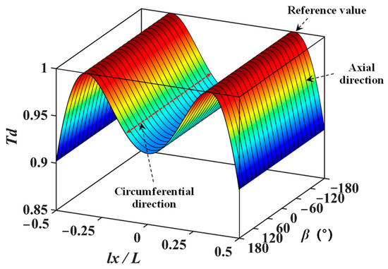
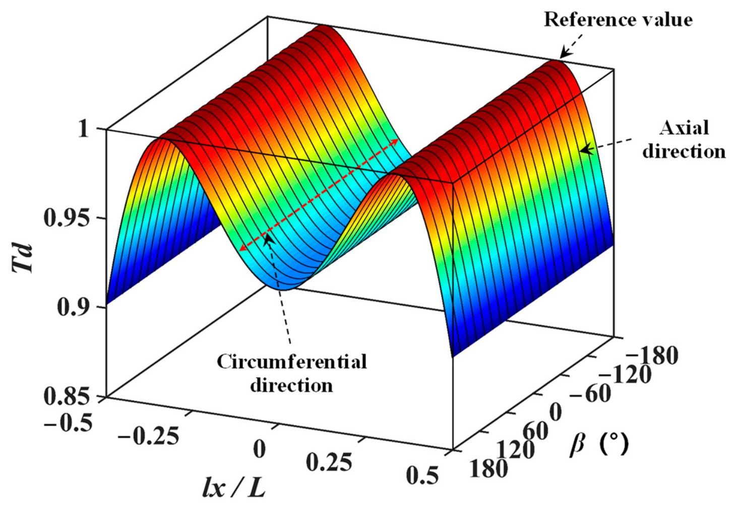
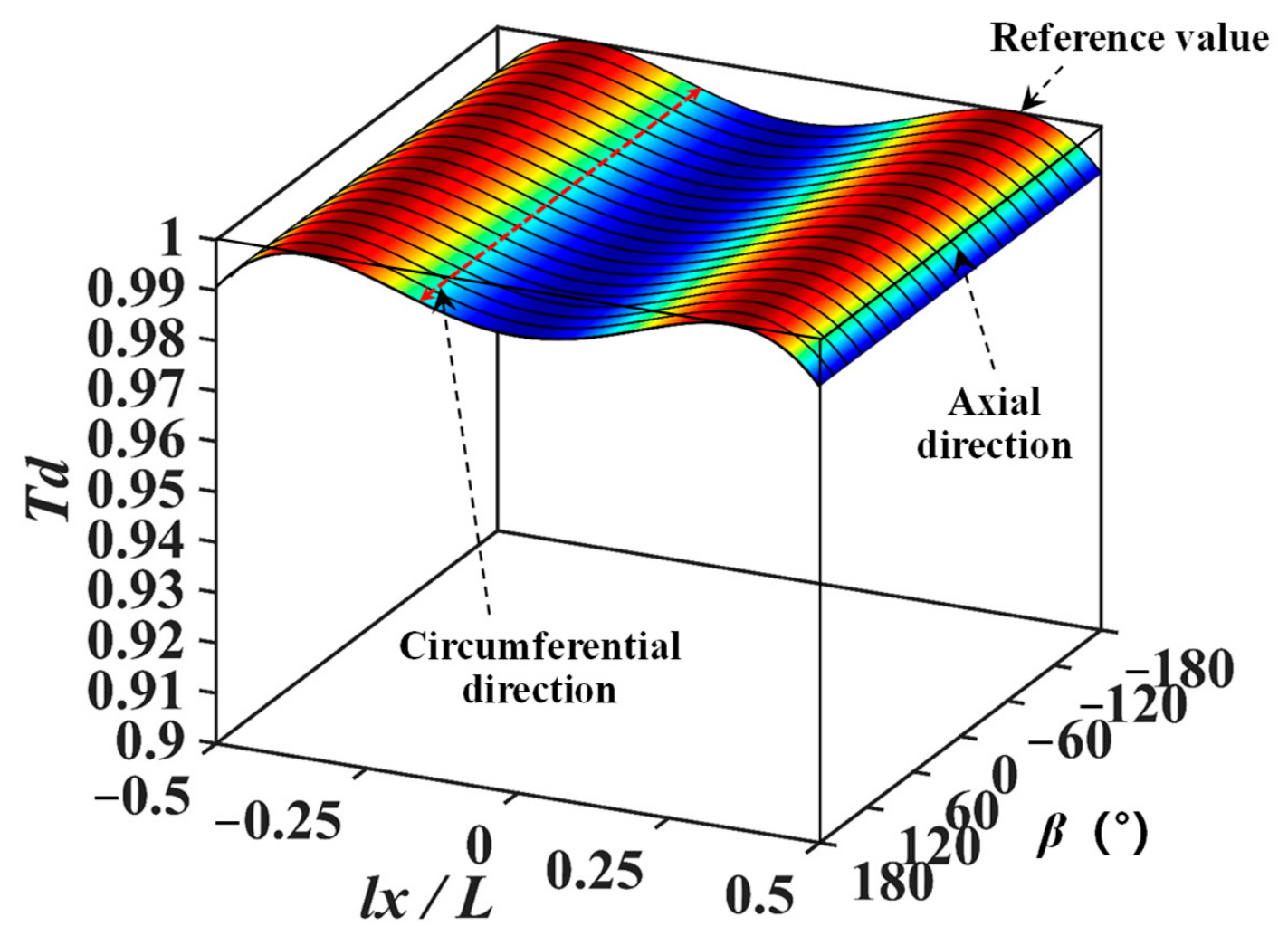
Based on the exemplary cylinder proposed in Section 2.2.1, the RTD under biaxial rotation can be calculated. Assuming that the coating parameters are consistent with those in the stationary case, where the distance from the evaporation source to the x axis b = 2.3R = 230 mm, and the distance from the evaporation source to the z axis a = 0.5L = 150 mm, the RTD is shown in Figure 5, and the meaning of the coordinate axis in the figure is consistent with that in the stationary case.
Figure 5.
Relative thickness distribution under simultaneous biaxial rotation of the cylinder. (The color of the surface corresponds to the magnitude of the relative thickness distribution).
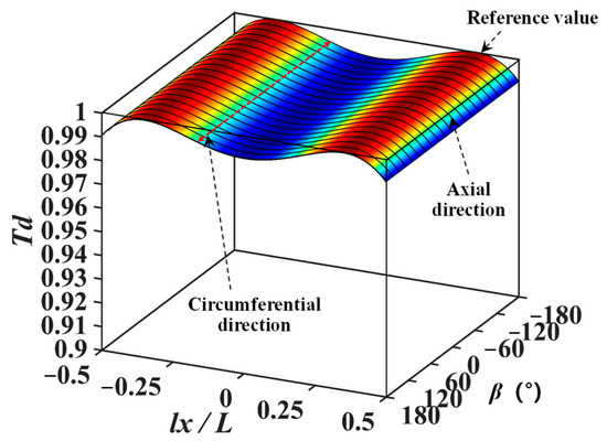
From the results, it is found that the deposition region covers the entire side surface of the cylinder (from −180° to 180°), and the variation of FTD is kept within 10%, indicating that the film thickness uniformity is greatly enhanced compared with that under stationary conditions. From the figure, it is observed that the axial FTD, which is represented by the black solid line, exhibits an M-shaped profile and is symmetric about the mid-position of the cylinder. The circumferential FTD, as indicated by the red dashed line, is shown to be uniform along the circumferential direction on the side surface. Therefore, during biaxial rotation coating, the two-dimensional FTD over the entire cylindrical surface is found to be uniform circumferentially and to vary along the axial direction.
From the above analytical results, it can be seen that the film thickness uniformity can be greatly improved by controlling the simultaneous biaxial rotation of the cylinder during the coating process. Therefore, it can be inferred that a film layer with higher thickness uniformity can be obtained by optimizing the biaxial rotation coating parameters a and b.
3. Analysis of Factors Influencing Film Thickness Uniformity
During the evaporation coating process, the positional parameters of the evaporation source are the primary factors influencing film thickness uniformity. These parameters include the distance b between the evaporation source and the cylinder axis, and the distance a between the evaporation source and the vertical rotation axis. Based on the exemplary cylinder proposed in Section 2.2.1, this section analyzes the influence of these coating process parameters on the FTD.
3.1. Influence of Distance b (Evaporation Source to Cylinder Axis)
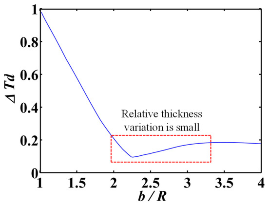
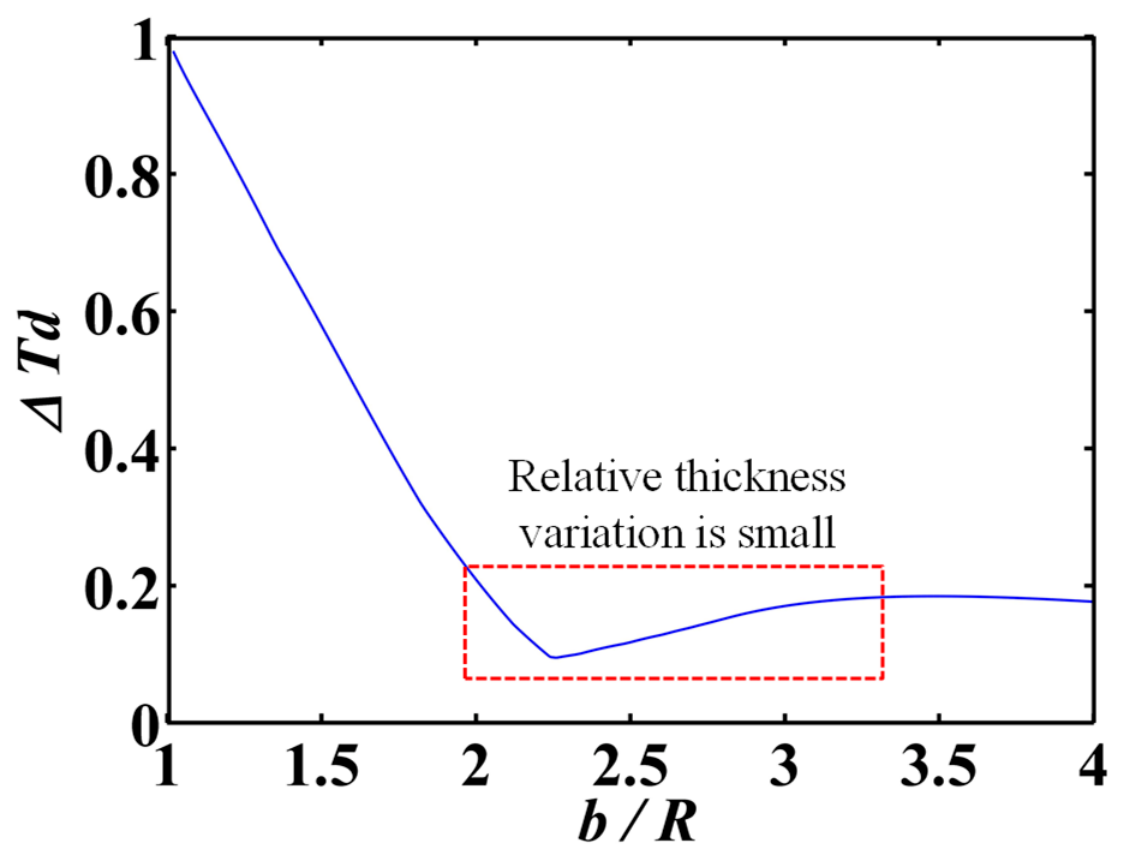
When analyzing the influence of the distance b between the evaporation source and the cylinder axis on the FTD, the relative thickness variation (RTV) ∆Td is calculated using the following formula:
In this formula, Td-max and Td-min represent the maximum and minimum values of the RTD, respectively.
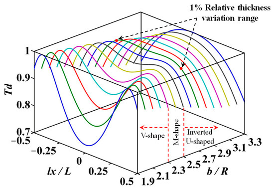
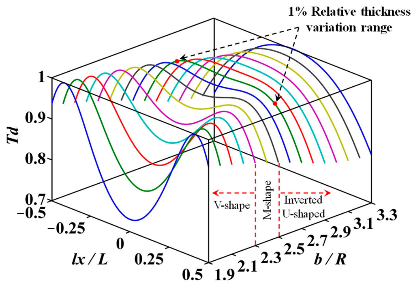
Assuming the distance between the evaporation source and the vertical rotation axis remains constant, and setting a = 0.5L = 150 mm, the distance b between the evaporation source and the cylinder axis is varied within the range R ≤ b ≤ 4R. The FTD was calculated at intervals of 0.1R, yielding the RTV ∆Td for different b values, as shown in Figure 6. As the ratio b/R increases, ∆Td decreases from 1 to approximately 0.1 and then gradually increases to 0.19. Within the red dashed rectangle in the figure, where ∆Td is relatively small, the corresponding b/R range is approximately 1.9 to 3.3. The axial FTDs within this range are presented in Figure 7, showing a transition from a V-shape to an M-shape and then to an inverted U-shape. The FTD at b/R = 2.4 agrees with that shown in Figure 5. At b/R = 2.7, the RTV is less than 1% over the central 60% of the cylinder length, corresponding to the region between the two red markers on the green curve in the figure.
Figure 6.
Relative film thickness variation corresponding to different distances b.
Figure 7.
Influence of distance b on film thickness distribution. (The colored lines represent the relative film thickness distribution under different parameter conditions).
Based on the above analysis, it can be determined that by adjusting the distance b between the evaporation source and the cylinder axis, a film layer with higher thickness uniformity can be obtained.
3.2. Influence of Distance a (Evaporation Source to Vertical Rotation Axis)
Next, we analyze the influence of the distance a between the evaporation source and the vertical rotation axis on the FTD.
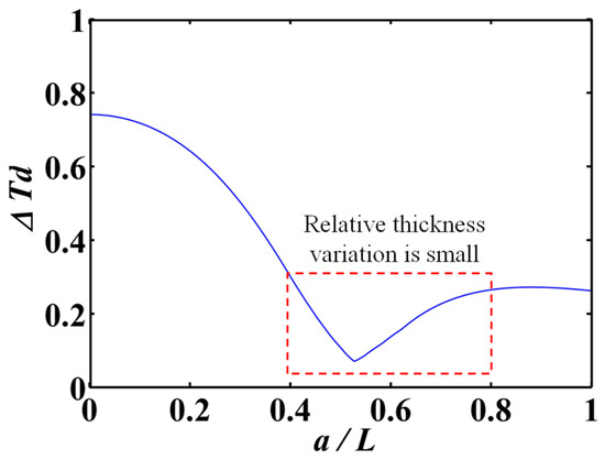
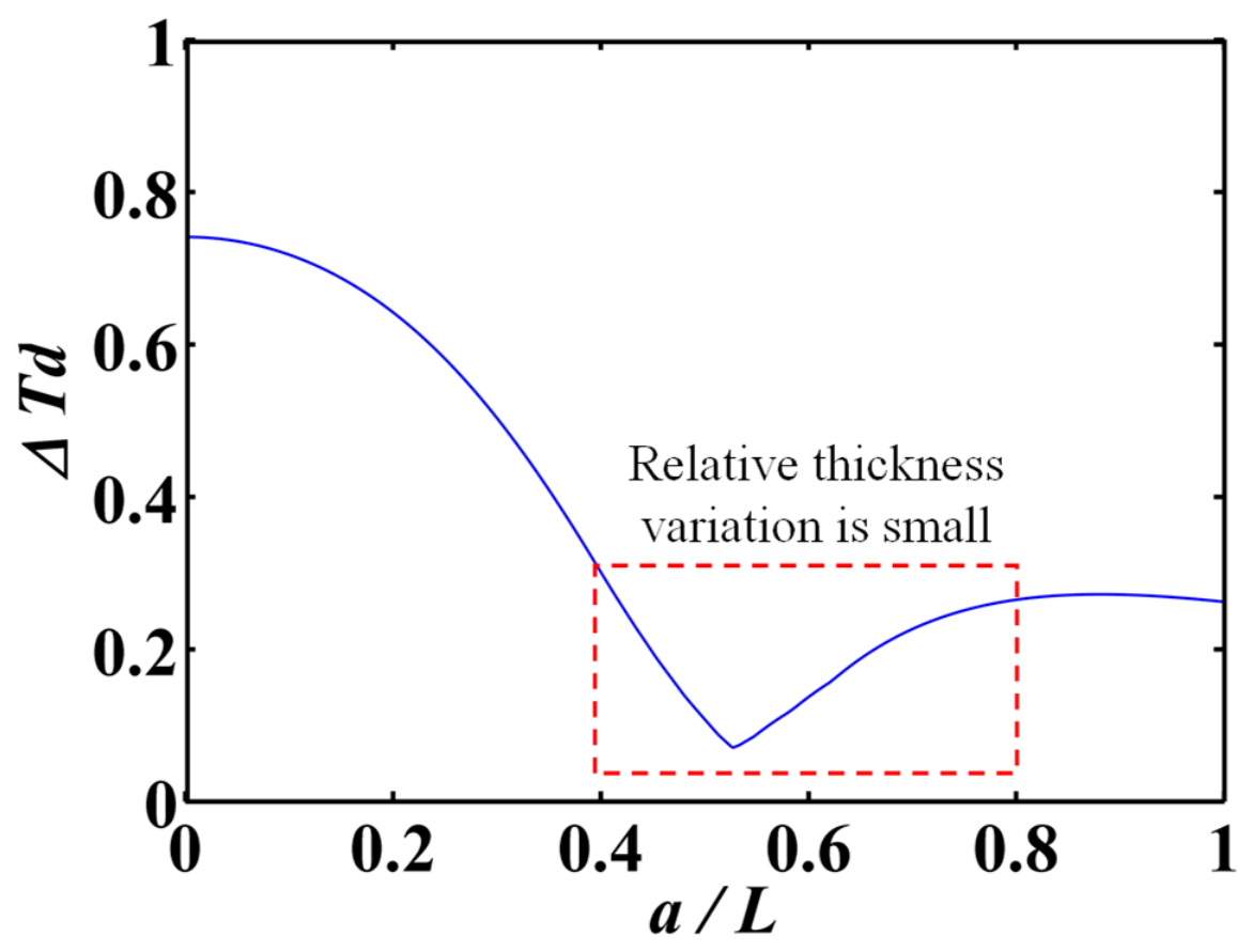
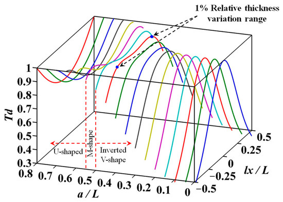
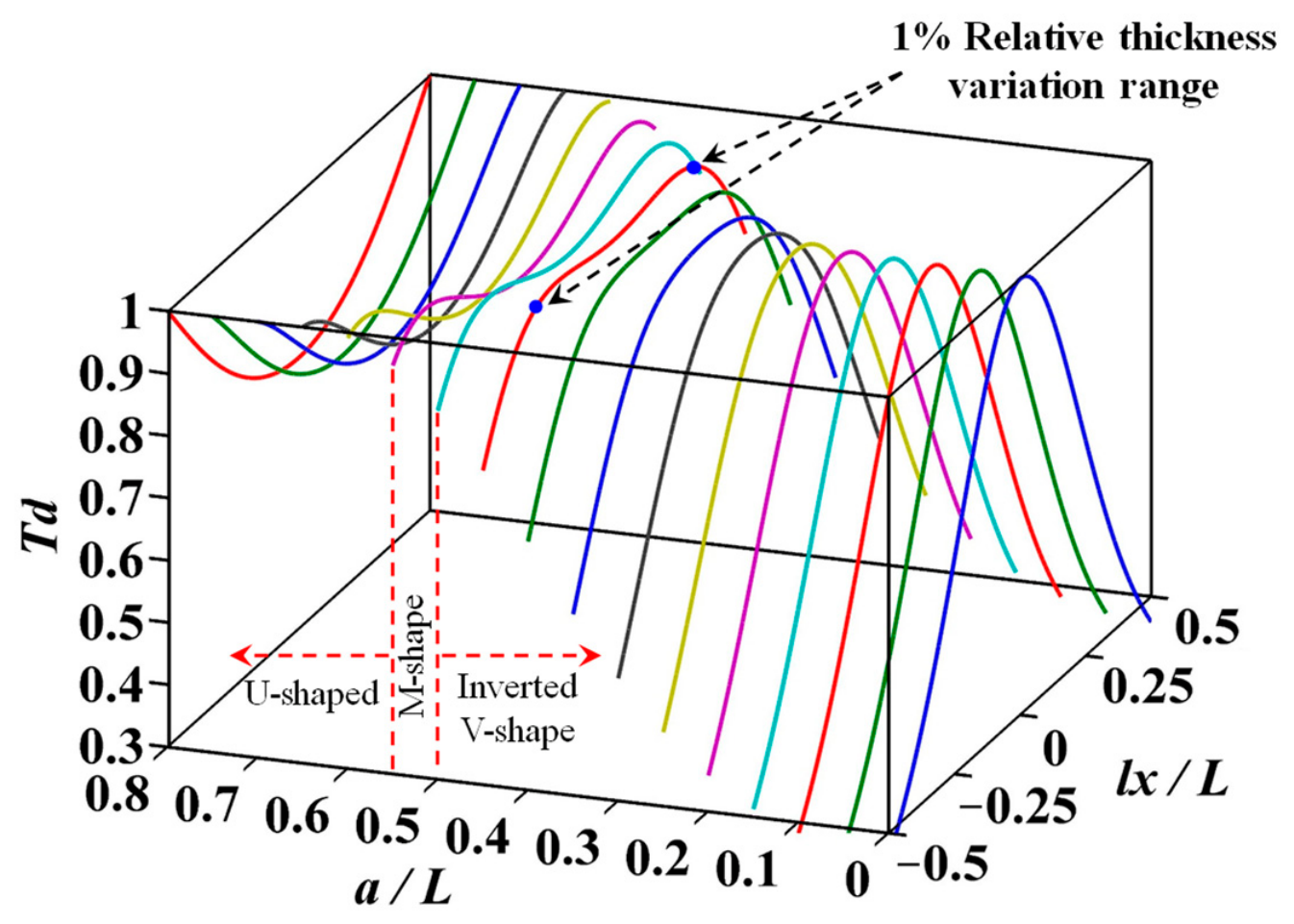
Assuming the distance b between the evaporation source and the cylinder axis remains constant, and setting b = 2.3R = 230 mm, the distance a between the evaporation source and the vertical rotation axis is varied within the range 0 ≤ a ≤ L. The FTD was calculated at intervals of 0.05L, yielding the RTV ∆Td for different a values, as shown in Figure 8. As the ratio a/L increases, ∆Td decreases from 0.75 to below 0.1 and then gradually increases to 0.25. Within the red dashed rectangle in the figure, where ∆Td is relatively small, the corresponding a/L range is approximately 0.4 to 0.8. Figure 9 shows the axial FTDs on the cylinder for different a/L values. As a/L increases from 0 to 0.8, the thickness profile transitions from an inverted V-shape to an M-shape and then to a U-shape. The FTD at a/L = 0.5 agrees with that shown in Figure 5. At a/L = 0.45, the RTV is less than 1% over the central 60% of the cylinder length, corresponding to the region between the two blue markers on the red curve in the figure.
Figure 8.
Relative film thickness variation corresponding to different distances a.
Figure 9.
Influence of distance a on film thickness distribution. (The colored lines represent the relative film thickness distribution under different parameter conditions).
Based on the above analysis, it can be determined that by adjusting the distance a between the evaporation source and the vertical rotation axis, a film layer with higher thickness uniformity can be obtained.
3.3. Combined Influences of Parameters a and b
The influence of parameters a and b on the FTD was analyzed individually in the preceding two sections. Following this, we investigate the combined influence of both parameters on the FTD.
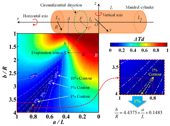
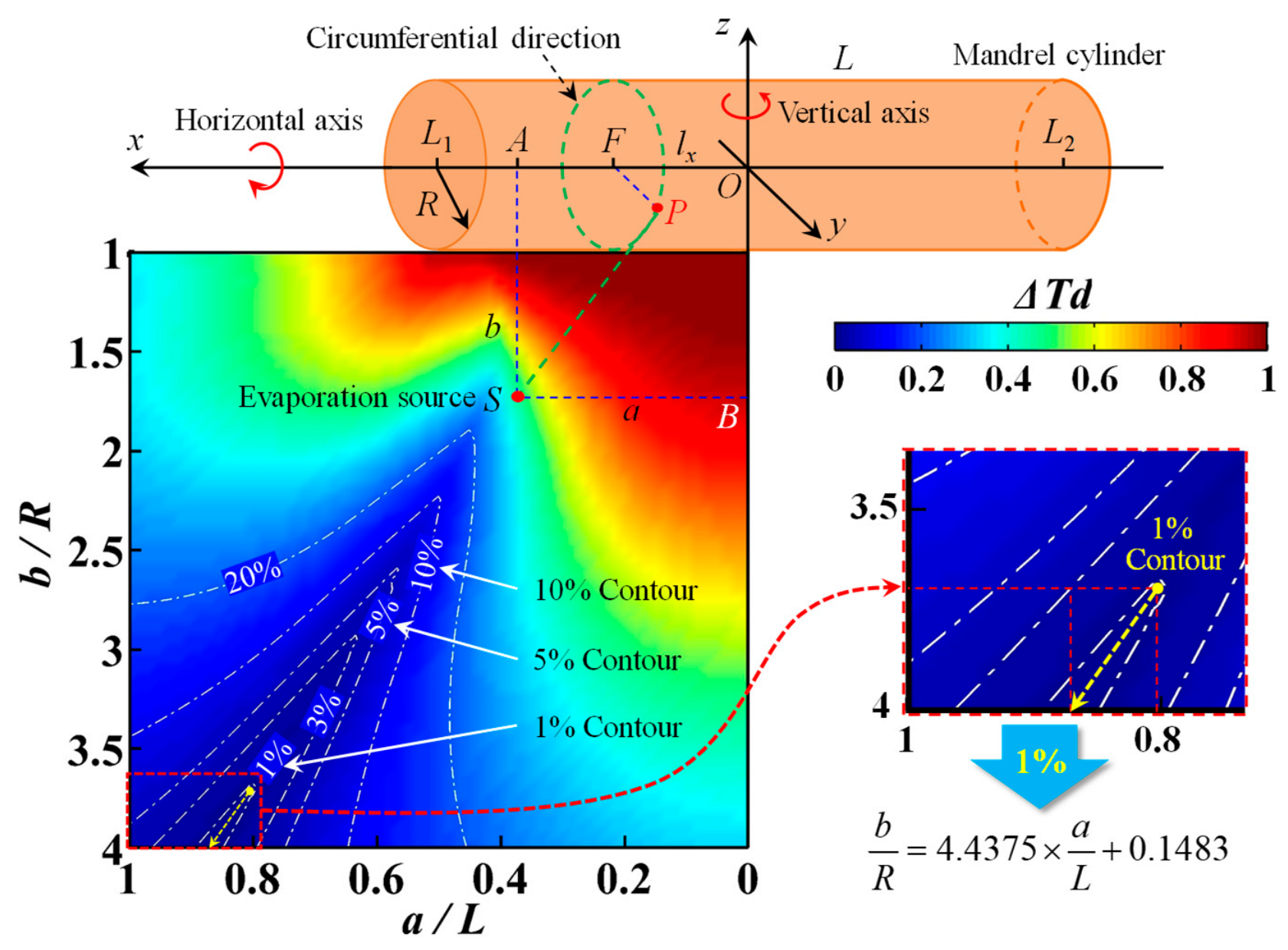
Assuming the distance a between the evaporation source and the vertical rotation axis varies within the range 0 ≤ a ≤ L at intervals of 0.05L, and simultaneously, the distance b between the evaporation source and the cylinder axis varies within the range R ≤ b ≤ 4R at intervals of 0.1R, the FTD for different combinations of parameters a and b was calculated. The corresponding RTV ∆Td was also determined, with the results presented in Figure 10.
Figure 10.
Variation of relative film thickness under the combined influence of distances a and b. (The color of the surface corresponds to the magnitude of the relative thickness variation).
In Figure 10, the abscissa represents the distance a between the evaporation source S and the z axis, the ordinate represents the distance b between the evaporation source S and the x axis, and different colors represent different RTV ∆Td. From the top-right corner to the bottom-left corner, the color distribution changes according to the rule of red, yellow, green and blue. This color gradient reveals that ∆Td is largest (indicating the poorest thickness uniformity) when the evaporation source is positioned close to both axes. Conversely, as the evaporation source moves away from both axes, ∆Td gradually decreases, signifying increasingly uniform FTD. The five white dash-dotted lines in the figure are contour lines, corresponding to the RTV of 20%, 10%, 5%, 3% and 1%, respectively.
When the coating parameters a and b are located inside the contour lines (lower-left side), a uniform film layer with thickness uniformity better than the value of the corresponding contour line can be obtained. Thus, it can be seen that a film layer with higher thickness uniformity can be obtained by optimizing the coating parameters a and b.
For the 1% contour line, the area enclosed by it is a narrow strip. The parameters a and b within this region can be approximately fitted as a ray, as shown by the yellow dashed line in Figure 10, and this ray can be represented by the following formula:
When coating parameters a and b meet the above formula, and the following preconditions (cylinder radius R is 100 mm, length L is 300 mm, vertical rotation axis is located in the middle of the cylinder, biaxial rotation coating) are satisfied, a film thickness uniformity better than 1% will be achieved for the entire side surface of the cylinder. As shown in Figure 11, the RTD obtained under the qualified coating parameters (a = 0.8L = 240 mm and b = 3.7R = 370 mm) is presented. It can be observed that the distribution pattern is similar to that in Figure 5, exhibiting an M-shaped profile, but with superior uniformity, as the RTV is reduced to within 1%.
Figure 11.
Film thickness distribution of 1% film thickness uniformity under specific parameters. (The color of the surface corresponds to the magnitude of the relative thickness distribution).
It should be noted that when the cylinder sizes are changed, the corresponding ray formula that satisfies the 1% uniformity will also be changed. Therefore, it is necessary to calculate the corresponding ray formula for different sizes mandrel cylinders by using the theoretical model of FTD.
4. Experiments: Verification of Film Thickness Distribution
To validate the accuracy of the FTD theory, a coating experiment was conducted on a mandrel cylinder.
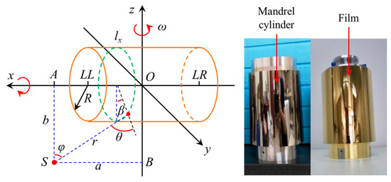
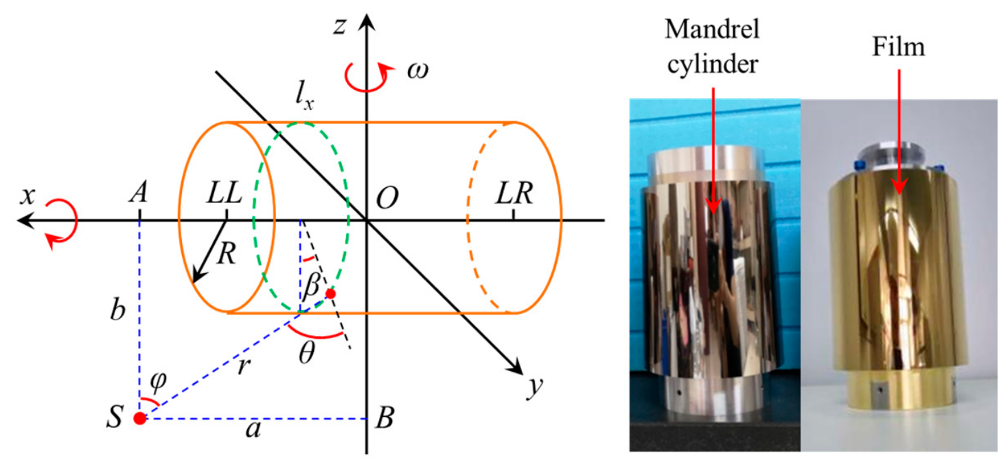
Figure 12 shows the schematic diagram of the coating scheme for the experimental cylinder and the photos of the cylinder before and after coating. The experimental cylinder had a length L = 210 mm and a radius R = 182.5 mm. The material used for coating is gold. The type of evaporation source is a hemispherical tungsten evaporation boat with a diameter of 15 mm. The average evaporation rate is about 0.2 nm/s. The vacuum degree of the coating environment is 1 × 10⁻³ Pa. During coating, the horizontal axis was rotated at 150 r/min, and the vertical axis at 25 r/min, and the deposition lasted for approximately 12 min. The mandrel cylinder is a bright mirror before coating and turns golden after coating.
Figure 12.
Coating scheme of experimental cylinder and the coated cylinder. (The meanings of the various symbols in the schematic diagram are similar to those in Figure 4).
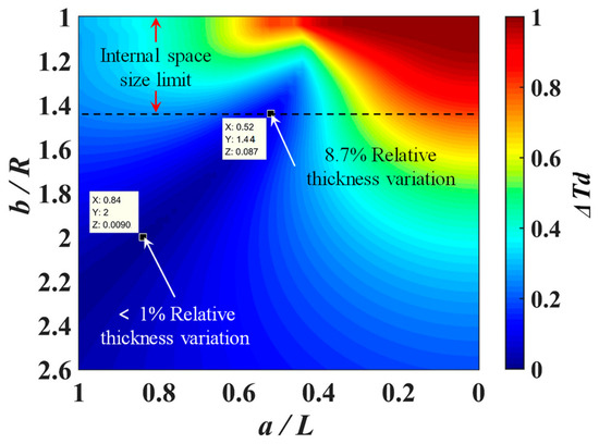
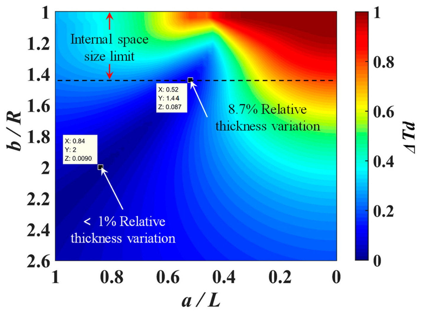
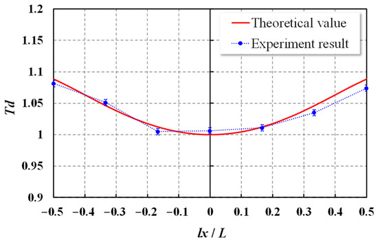
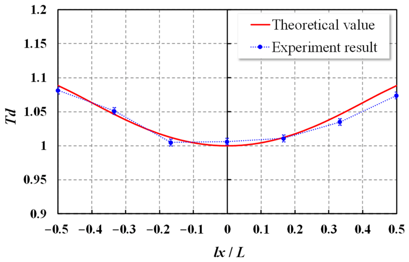
By substituting the above coating parameters into the theoretical model of FTD, the corresponding RTV for the experimental cylinder under different coating schemes can be calculated, as shown in Figure 13. According to the theoretical model, when the parameters a = 0.84L = 176.4 mm and b = 2R = 365 mm are set, a film with uniformity better than 1% can be obtained. However, the selectable range of practical coating parameters is limited by the internal space dimensions of the coating equipment, as shown by the black dashed line in Figure 13. Under the constraint of the equipment space, when the parameters a = 0.52L = 109.2 mm and b = 1.44R = 262.8 mm, the theoretically optimal film thickness uniformity can be obtained, at which the RTV is about 8.7%, and the corresponding FTD curve is shown by the red solid line in Figure 14. It can be seen that the theoretical FTD of the experimental cylinder is symmetrical about its midpoint, which is characterized by being thin in the middle and thick at both ends.
Figure 13.
Relative film thickness variation corresponding to different coating parameters.
Figure 14.
Comparison between experimental film thickness distribution and theoretical value.
Since the FTD obtained by biaxial rotation coating is uniform along the circumferential direction of the mandrel, in order to obtain the FTD of the coating experiment, seven thin witness sheets of identical thickness were fixed at equal intervals along the axial direction on the side surface of the cylinder. Before coating, half of the surface of each witness sheet was covered with high-temperature-resistant 3M tape. After coating, a step was formed on the surface of the witness sheet. The film thickness on the witness sheet could then be obtained by measuring the step height using a stylus profilometer. The profilometer had a measurement resolution of 0.1 nm and a measurement repeatability of 0.4 nm, and it was regularly calibrated using step-height standards to ensure the accuracy of the instrument. For each witness sheet, measure 10 times and take the average value as the film thickness. To increase the reliability of the experimental results, two coating experiments were conducted, and the average values were taken as the final results. In Figure 14, the blue dots are the FTD obtained from the experiment, the maximum RTV is 7.5%. The vertical dashed segments in the figure are error bars, and the measurement error is approximately 0.5%, which is mainly composed of the repeatability error of thickness measurement, the error introduced by fractional rotation cycles, and the film thickness error caused by the bonding angle of the witness sheets.
Through comparative analysis, a difference of 1.2% is found between the theoretical value (8.7%) and the experimental result (7.5%), indicating that the experimental FTD is in good agreement with the theoretical prediction. Thus, the validity of the theoretical model of FTD is verified. The deviation between experiment and theory is mainly attributed to the positional deviation of the evaporation source, the bonding position deviation of the witness sheets, and the thickness measurement deviation. Meanwhile, the experimental cylinder has a parabolic shape, while the theoretical model assumes a cylindrical shape; this geometrical discrepancy is also a source of error.
It should be noted in particular that the above coating experiments verified the correctness of the theoretical FTD model, but failed to verify the theoretical prediction of 1% ultimate film thickness uniformity. This was mainly attributed to the limited internal space of the coating equipment, which prevented the arbitrary setting of the coating parameters. In addition, the film thickness uniformity of 7.5% obtained from the coating experiments was sufficient to meet the mission requirements. Therefore, no further studies on uniformity improvement were carried out. In the future, in-depth research on the 1% ultimate film thickness uniformity will be conducted by either reducing the size of the mandrel cylinder or replacing the coating equipment with a larger-space one.
5. Conclusions
This research approximates the parabolic cylinder as a cylindrical substrate and investigates FTD models under both stationary and simultaneous biaxial rotation conditions, based on classical thin-film deposition theory. Theoretical formulas for FTD were derived. Using these formulas, the influence of various deposition parameters on thickness uniformity was systematically analyzed, leading to the determination of FTD characteristics under three scenarios: variation in distance b between the evaporation source and cylinder axis, variation in distance a between the evaporation source and vertical rotation axis, and combined variation of parameters a and b. According to the models, the uniformity of FTD can be greatly improved by optimizing the coating parameters. Experimental coating trials confirmed strong agreement between actual FTDs and theoretical predictions, validating the accuracy of the proposed model. The optimization of film thickness uniformity proposed in this paper refers to the rapid determination of appropriate coating process parameters based on the theoretical model, mainly the optimization of the coating process. This research provides a method to replace traditional empirical or iterative approaches for determining coating process parameters, thereby enhancing work efficiency and reducing costs. Furthermore, the findings offer a theoretical and technical foundation for developing FTD models for coatings on complex curved surfaces.
Author Contributions
Conceptualization, H.Z. and Y.Y.; methodology, L.L.; software, Y.S.; validation, H.Z. and H.W.; formal analysis, Y.S.; investigation, H.Z.; resources, Z.M.; data curation, H.W. and Q.Z.; writing—original draft preparation, H.Z.; writing—review and editing, Y.Y.; visualization, Y.S.; supervision, Y.Y.; project administration, L.L.; funding acquisition, Z.M. All authors have read and agreed to the published version of the manuscript.
Funding
This research was funded by the National Major Scientific Research Instrument Development Project of the National Natural Science Foundation of China, grant number 42327802.
Institutional Review Board Statement
Not applicable.
Informed Consent Statement
Not applicable.
Data Availability Statement
The original contributions presented in this study are included in the article. Further inquiries can be directed to the corresponding author.
Conflicts of Interest
The authors declare no conflicts of interest.
Abbreviations
The following abbreviations are used in this manuscript:
| FTD | Film Thickness Distribution |
| RTD | Relative Thickness Distribution |
| RTV | Relative Thickness Variation |
Nomenclature
| a | Distance between evaporation source and vertical axis (mm) |
| a1 | Distance between evaporation source and vertical axis under biaxial rotation (mm) |
| b | Distance between evaporation source and horizontal axis (mm) |
| b1 | Distance between evaporation source and horizontal axis under biaxial rotation (mm) |
| L | Length of mandrel cylinder (mm) |
| L1 | Length of cylinder in the positive direction of the horizontal x axis (mm) |
| L2 | Length of cylinder in the negative direction of the horizontal x axis (mm) |
| lx | Distance between the center F of any circumferential and the coordinate origin O (mm) |
| m | Total mass of coating material (g) |
| r | Distance between any point P on the side of the cylinder and the evaporation source S (mm) |
| R | Radius of mandrel cylinder (mm) |
| r1 | Distance between any point P on the side of the cylinder and the evaporation source S under biaxial rotation (mm) |
| t | Film thickness on cylinder side (nm) |
| td | Film thickness on cylinder side under biaxial rotation (nm) |
| Td | Relative film thickness on the cylinder side under biaxial rotation |
| td-max | Maximum film thickness on the cylinder side under biaxial rotation (nm) |
| Td-max | Maximum relative film thickness on the cylinder side under biaxial rotation |
| Td-min | Minimum relative film thickness on the cylinder side under biaxial rotation |
| ts | Film thickness on the cylinder side under stationary (nm) |
| Ts | Relative film thickness on the cylinder side under stationary |
| ts-max | Maximum film thickness on the cylinder side under stationary (nm) |
| β | Rotation angle of cylinder surface element relative to the lowest point (°) |
| βmax | Maximum angle of the coating range of the cylinder under stationary (°) |
| δ | Variation of the projection angle of the evaporation source on the horizontal axis under biaxial rotation (°) |
| θ | Angle between the normal of the cylinder surface element and the emission direction (°) |
| ρ | Density of coating material (g/cm3) |
| φ | Emission angle of evaporation source (°) |
| ω | Rotation angle of cylinder in horizontal under biaxial rotation (°) |
| ∆Td | Relative film thickness variation on the cylinder side under biaxial rotation |
References
- Sheikh, S.I. The Use of Variable Celestial X-Ray Sources for Spacecraft Navigation. Doctoral Dissertation, University of Maryland, College Park, MD, USA, 2005. [Google Scholar]
- Zhang, W.; Ma, X.; Chen, X.; Xu, J.; Sun, X.M.; Cui, P.L. X-ray pulsar navigation based on phase and Doppler frequency shift using double-differenced. IEEE Trans. Instrum. Meas. 2024, 73, 3520015. [Google Scholar] [CrossRef] [Scilit]
- Buist, P.J.; Engelen, S.; Noroozi, A.; Sundaramoorthy, P.; Verhagen, S.; Verhoeven, C. Overview of pulsar navigation: Past, present and future trends. Navigation 2011, 58, 153–164. [Google Scholar] [CrossRef] [Scilit]
- Liu, J.; Ma, J.; Tian, J.W.; Kang, Z.W.; White, P. X-ray pulsar navigation method for spacecraft with pulsar direction error. Adv. Space Res. 2010, 46, 1409–1417. [Google Scholar] [CrossRef] [Scilit]
- Ely, T.; Bhaskaran, S.; Bradley, N.; Lazio, T.J.W.; Martin-Mur, T. Comparison of deep space navigation using optical imaging, pulsar time-of-arrival tracking, and/or radiometric tracking. J. Astronaut. Sci. 2022, 69, 385–472. [Google Scholar] [CrossRef] [Scilit] [PubMed]
- Lin, Q.Q.; Shuai, P.; Huang, L.W.; Zhang, X.Y.; Chen, S.L.; Wu, Y.J.; Bei, X.M.; Meng, J. TOA estimation methods for the observation data based on the X-ray pulsar-based navigation-1 (XPNAV-1) satellite. Chin. Space Sci. Technol. 2018, 38, 1–7. [Google Scholar] [CrossRef] [Scilit]
- Winternitz, L.B.; Hassouneh, M.A.; Mitchell, J.W.; Price, S.R.; Yu, W.H.; Semper, S.R.; Ray, P.S.; Wood, K.S.; Arzoumanian, Z.; Gendreau, K.C. SEXTANT X-ray pulsar navigation demonstration: Additional on-orbit results. In Proceedings of the SpaceOps, Marseille, France, 28 May–1 June 2018; p. 2538. [Google Scholar]
- Chen, P.T.; Zhou, B.; Speyer, J.L.; Bayard, D.S.; Majid, W.A.; Wood, L.J. Aspects of pulsar navigation for deep space mission applications. J. Astronaut. Sci. 2020, 67, 704–739. [Google Scholar] [CrossRef] [Scilit]
- Huang, L.; Shuai, P.; Zhang, X.; Chen, S. Pulsar-based navigation results: Data processing of the x-ray pulsar navigation-I telescope. J. Astron. Telesc. Instrum. Syst. 2019, 5, 018003. [Google Scholar] [CrossRef] [Scilit]
- Aschenbach, B. X-ray telescopes. Rep. Prog. Phys. 1985, 48, 579. [Google Scholar] [CrossRef] [Scilit]
- Pareschi, G.; Spiga, D.; Pelliciari, C. X-ray telescopes based on Wolter-I optics. In The WSPC Handbook of Astronomical Instrumentation; World Scientific: Hackensack, NJ, USA, 2021; Volume 4, pp. 3–31. [Google Scholar]
- Shi, Y.Q.; Xi, T.X.; Xin, Y.M.; Chen, J.W.; Deng, L.L.; Lv, Z.X.; Mei, Z.W. The Energy response Calibration of focusing X-ray pulsar telescope (FXPT). Aerosp. Control Appl. 2018, 44, 34–39. [Google Scholar]
- Franks, A. X-ray telescope mirrors-materials, manufacture, tolerances and metrology. Proc. SPIE 1979, 184, 110–122. [Google Scholar] [CrossRef] [Scilit]
- Harvey, J.E.; Thompson, P.L.; Vernold, C.L. Surface scatter effects in grazing incidence x-ray telescopes. Proc. SPIE 1998, 3444, 518–525. [Google Scholar] [CrossRef] [Scilit]
- Cash, W. X-ray optics: A technique for high resolution imaging. Appl. Opt. 1987, 26, 2915–2920. [Google Scholar] [CrossRef] [Scilit] [PubMed]
- Kotlikov, E.N.; Prokashev, V.N.; Ivanov, V.A.; Tropin, A.N. Thickness uniformity of films deposited on rotating substrates. J. Opt. Technol. 2009, 76, 100–103. [Google Scholar] [CrossRef] [Scilit]
- Gross, M.; Dligatch, S.; Chtanov, A. Optimization of coating uniformity in an ion beam sputtering system using a modified planetary rotation method. Appl. Opt. 2011, 50, C316–C320. [Google Scholar] [CrossRef] [Scilit] [PubMed]
- Wang, B.; Fu, X.; Song, S.; Chu, H.O.; Gibson, D.; Li, C.; Wu, Z. Simulation and optimization of film thickness uniformity in physical vapor deposition. Coatings 2018, 8, 325. [Google Scholar] [CrossRef] [Scilit]
- Wang, G.; Bai, Y.; Zhao, J.; Wang, L.; Zhang, J.; Zhou, Y. Optimization of thickness uniformity distribution on a large-aperture concave reflective mirror and shadow mask design in a planetary rotation system. Coatings 2021, 11, 140. [Google Scholar] [CrossRef] [Scilit]
- Ramprasad, B.S.; Radha, T.S. Uniformity of film thickness on rotating planetary planar substrates. Thin Solid Films 1973, 15, 55–64. [Google Scholar] [CrossRef] [Scilit]
- Liu, C.; Guo, C.; Kong, M.; Li, B. Geometry optimization in planetary rotation stage for thickness uniformity of films on spherical substrates. Chin. Opt. Lett. 2013, 11, S10213. [Google Scholar] [CrossRef] [Scilit]
- Liu, C.; Kong, M.; Guo, C.; Gao, W.; Li, B. Theoretical design of shadowing masks for uniform coatings on spherical substrates in planetary rotation systems. Opt. Express 2012, 20, 23790–23797. [Google Scholar] [CrossRef] [Scilit] [PubMed]
- Sun, J.; Zhang, W.; Yi, K.; Shao, J. Optimization of thickness uniformity of coatings on spherical substrates using shadow masks in a planetary rotation system. Chin. Opt. Lett. 2014, 12, 053101. [Google Scholar] [CrossRef] [Scilit]
- Zhang, Z.; Qi, R.; Yao, Y.; Shi, Y.; Li, W.; Huang, Q.; Yi, S.; Zhang, Z.; Wang, Z.; Xie, C. Improving thickness uniformity of Mo/Si multilayers on curved spherical substrates by a masking technique. Coatings 2019, 9, 851. [Google Scholar] [CrossRef] [Scilit]
- Guo, C.; Kong, M.; Liu, C.; Li, B. Optimization of thickness uniformity of optical coatings on a conical substrate in a planetary rotation system. Appl. Opt. 2013, 52, B26–B32. [Google Scholar] [CrossRef] [Scilit] [PubMed]
- Zhang, Y.; Li, W.; Li, D.; Xiao, J.; Zhang, C. Modeling of thickness and profile uniformity of thermally sprayed coatings deposited on cylinders. J. Therm. Spray Technol. 2017, 27, 288–295. [Google Scholar] [CrossRef] [Scilit]
- Wang, C.; Jian, X.; Yang, Q.; Sun, K.; Zhang, S. Theoretical and experimental study on coating uniformity in automatic spray-coating of pipeline weld repairs. Coatings 2025, 15, 1193. [Google Scholar] [CrossRef] [Scilit]
- Hass, D.D.; Marciano, Y.; Wadley, H.N.G. Physical vapor deposition on cylindrical substrates. Surf. Coat. Technol. 2004, 185, 283–291. [Google Scholar] [CrossRef] [Scilit]
- Cui, J.; Tian, X.; Yang, S.; Hu, T.; Fu, R.K.Y.; Chu, P.K. Uniformity of plasma density and film thickness of coatings deposited inside a cylindrical tube by radio frequency sputtering. Plasma Sci. Technol. 2008, 10, 621–625. [Google Scholar] [CrossRef] [Scilit]
- Loffler, F.; Siewert, C. Homogeneous coatings inside cylinders. Surf. Coat. Technol. 2004, 177–178, 355–359. [Google Scholar] [CrossRef] [Scilit]
- Tahir, U.; Kamran, M.A.; Jang, M.H.; Jeong, M.Y. Thin-film coating on cylinder for fabrication of cylindrical mold: Roll-to-roll nano-imprint lithography. Microelectron. Eng. 2019, 211, 5–12. [Google Scholar] [CrossRef] [Scilit]
- Huang, Y.X.; Wen, W.Y.; Sun, J.W.; Huai, C.F.; Zeng, H.F.; Zhong, F.H. Thickness uniformity control of sputtered film based on roll-to-roll system with a rectangular target. J. South China Univ. Technol. Nat. Sci. Ed. 2015, 43, 81–86. [Google Scholar]
- Yamaguchi, G.; Kume, T.; Takeo, Y.; Matsuzawa, Y.; Hiraguri, K.; Imamura, Y.; Miyashita, H.; Tamura, K.; Takehara, Y.; Takigawa, A.; et al. Development of precise electroformed Wolter mirror for X-ray astronomy. Proc. SPIE 2020, 11491, 63–68. [Google Scholar] [CrossRef] [Scilit]
- Yamaguchi, G.; Matsuzawa, Y.; Kume, T.; Imamura, Y.; Miyashita, H.; Ito, A.; Sakuta, K.; Ampuku, K.; Fujii, R.; Hiraguri, K.; et al. Efficient and precise fabrication of Wolter type-I x-ray mirrors via nickel electroforming replication using quartz glass mandrels. Rev. Sci. Instrum. 2023, 94, 124501. [Google Scholar] [CrossRef] [Scilit] [PubMed]
- Singam, P.; Speegle, C.; Meekham, A.; Kolodziejczak, J.; Banks, D.; Baumgartner, W.; Gaskin, J.; Bongiorno, S.; Ramsey, B.; Smith, D.D.; et al. Optimizing the electroforming process for full-shell X-ray optics. J. Astron. Telesc. Instrum. Syst. 2024, 10, 034001. [Google Scholar] [CrossRef] [Scilit]
- Li, Y.M.; Deng, L.L.; Yang, J.; Tian, X.Y.; Zuo, F.C.; Shen, K.; Xie, J. Manufacturing Technology and Application Development of Electroformed Nickel Wolter—I Optical System. Aerosp. Control Appl. 2018, 46, 8–16. [Google Scholar]
- Holland, L. Vacuum Deposition of Thin Films; Wiley: New York, NY, USA, 1956. [Google Scholar]
Disclaimer/Publisher’s Note: The statements, opinions and data contained in all publications are solely those of the individual author(s) and contributor(s) and not of MDPI and/or the editor(s). MDPI and/or the editor(s) disclaim responsibility for any injury to people or property resulting from any ideas, methods, instructions or products referred to in the content. |
© 2026 by the authors. Licensee MDPI, Basel, Switzerland. This article is an open access article distributed under the terms and conditions of the Creative Commons Attribution (CC BY) license.