


Abstract
Lithium–sulfur (Li–S) batteries hold great promise for next-generation energy storage owing to their ultrahigh theoretical energy density; however, their practical application is severely hampered by the polysulfide shuttle effect and the penetration of lithium dendrites through the separator. In this work, a carboxyl-containing anionic polymer (TPU-DMBA) is synthesized and composited with Ketjen Black (KB), and the resulting mixture is coated onto a commercial polypropylene separator via a simple doctor-blade method. In this design, the porous KB network provides physical adsorption to capture polysulfides, while the dissociated carboxylate groups (–COO−) generate strong electrostatic repulsion against negatively charged polysulfide anions (Sn2−). This dual-mechanism strategy—adding electrostatic repulsion on the basis of physical adsorption—effectively suppresses the shuttle effect. In addition, the flexible polymer backbone increases the tensile strength of the separator by approximately 30%, enhancing its resistance against dendrite penetration. The carbon material also significantly improves electrolyte wettability (the contact angle decreases from 41.6° to 11.7°) and ionic conductivity (from 0.48 × 10⁻³ to 0.88 × 10⁻³ S cm−1). The polymer itself acts as a binder, eliminating the need for additional binder addition. Benefiting from the synergy of electrostatic repulsion, physical adsorption, and mechanical reinforcement, the prepared modified separator endows the Li–S battery with an initial specific discharge capacity of 1373.15 mAh g−1 at 0.1 C and an initial discharge capacity of 714.46 mAh g−1 at a high rate of 2 C. After 200 cycles at 2 C, the capacity remains 577.93 mAh g−1, with a capacity retention of 80.89%. This work provides a low-cost, scalable, and binder-free separator modification strategy that simultaneously suppresses the polysulfide shuttle and resists dendrite growth, opening a new and effective pathway toward practical high-performance Li–S batteries.
1. Introduction
With the continuously growing demand for long-range electric vehicles and large-scale energy storage systems, the market requirements for battery energy density have steadily increased, surpassing the performance limits of current lithium-ion batteries [1,2,3]. Therefore, the development of energy storage devices with higher energy density has become a key direction to drive technological advances in this field [4,5,6]. Lithium–sulfur (Li–S) batteries, with their significantly higher theoretical specific capacity (1675 mAh g−1) and energy density (2600 Wh kg−1) compared to conventional lithium–ion batteries, are regarded as a highly promising next-generation energy storage technology [7,8,9]. However, the commercialization of Li–S batteries remains hindered by multiple technical bottlenecks, including the insulating nature of sulfur and its discharge products, the polysulfide shuttle effect, poor thermal stability of separators, and uncontrolled lithium dendrite growth [10,11,12]. Among these, the migration of soluble polysulfide intermediates across the commercial separator not only reduces active material utilization and accelerates capacity decay, but also leads to a deterioration in overall battery performance [13,14].
As a critical component of batteries, the separator plays a key role in maintaining lithium-ion conduction and electronic insulation, serving as a physical barrier to prevent direct contact between the positive and negative electrodes while regulating lithium-ion transport. Therefore, separator modification is regarded as one of the most direct and effective strategies to inhibit the polysulfide shuttle. To suppress the shuttle effect, various strategies have been explored, including physical confinement, chemical adsorption, and catalytic conversion [15,16]. Porous carbon materials, graphene, carbon nanotubes, and the like are frequently employed as modifying layers for polypropylene separators due to their high specific surface area [17], abundant pore structures, and good electrical conductivity, thereby physically restricting the migration of polysulfides [18,19]. However, the weak affinity of such carbonaceous materials toward polar polysulfides limits their shuttle-suppressing efficacy.
Surface modification of carbon materials is an effective approach to enhancing their polysulfide barrier properties. For example, coating the surface of carbon nanotubes with an adsorbed layer of MOFs or COFs can significantly improve the electrochemical performance of batteries [20,21]. However, such framework materials often suffer from poor stability and are prone to decomposition; furthermore, due to high production costs and cumbersome processes, they are difficult to implement on a practical scale. In contrast, Yan [22] significantly improved the mechanical properties of the separator by constructing a functionalized, stable coating on a carboxylated aramid nanofiber separator, thereby effectively suppressing the penetration and growth of lithium dendrites and enhancing the battery’s cycling stability. In fact, lithium-sulfur batteries face multiple challenges, including polysulfide shuttling, lithium dendrite penetration, and poor electrolyte wettability; a single modification strategy struggles to address all these issues simultaneously [23]. Therefore, there is an urgent need for a more practical strategy that can synergistically address these challenges using low-cost, scalable materials and simple fabrication methods. An ideal lithium-sulfur battery separator should not only effectively block polysulfide shuttling but also possess excellent mechanical properties to resist lithium dendrite penetration [24,25].
Accordingly, we employed a two-step polymerization method using PTMEG-1000 as the soft segment, IPDI as the hard segment, and DMBA as the functional chain extender to successfully synthesize a carboxyl-containing anionic polymer (TPU-DMBA). This polymer was compounded with Ketjen Black (KB) to prepare a lithium-sulfur battery separator via the doctor blade coating method. This separator exhibited a high capacity of 973.08 mAh g−1 at a 1 C rate. Its superior performance is attributed to the following synergistic effects: carboxyl anions on the polymer chains exert electrostatic repulsion against polysulfides; the carbon material improves electrolyte wettability and reduces ionic transport resistance; simultaneously, the flexible backbone of TPU-DMBA increases the separator’s tensile strength by approximately 30% and its toughness by approximately 75%, effectively resisting lithium dendrite penetration. In summary, this study integrates electrostatic repulsion, mechanical reinforcement, and ionic conductivity into a single, easily processable coating, simultaneously suppressing polysulfide shuttling and lithium dendrite growth, thereby significantly enhancing the overall performance of lithium-sulfur batteries.
2. Experimental Section
2.1. Preparation of Functional Material TPU-DMBA
Using 2,2-bis(hydroxymethyl)butyric acid (DMBA) as a functional chain extender, the carboxyl groups (–COOH) along its molecular chain provide the final polymer with the ability to electrostatically repel polysulfides. The polymerization was carried out via a two-step synthesis, employing polytetramethylene ether glycol (PTMEG-1000) as the soft segment and isophorone diisocyanate (IPDI) as the hard segment.
Pre-polymerization step: Under a dry nitrogen atmosphere, PTMEG-1000 (40.0 g, 0.04 mol) and IPDI (11.1 g, 0.05 mol) were accurately weighed in a molar ratio of n(PTMEG-1000):n(IPDI) = 0.8:1 and placed into a pre-dried 250 mL three-necked flask equipped with a magnetic stir bar. Subsequently, 20 μL of the catalyst DBTDL (approximately 0.02 g) was added to the system. The reaction mixture was heated to 80 °C and stirred continuously for 2 h to form the isocyanate-terminated polyurethane prepolymer.
Chain extension step: DMBA (1.34 g, 0.01 mol) was weighed according to the molar ratio n(DMBA): n(IPDI) = 0.2:1 and dissolved in an appropriate amount of NMP to prepare a solution with a solid content of approximately 40 wt%. Under continuous stirring at 80 °C, the above solution was slowly added dropwise to the prepolymer system. The reaction was kept at 80 °C for an additional 6 h to allow the chain extension to proceed completely, finally yielding an anionic polyurethane solution containing carboxyl functional groups TPU-DMBA.
2.2. Preparation of the Modified Separator
The TPU-DMBA solution and KB were mixed at a mass ratio of 8:2 (total mass 2 g), followed by the addition of 6 g of NMP. The mixture was magnetically stirred for 12 h to form a homogeneous and viscous slurry. The slurry was uniformly coated onto one side of a polypropylene (PP) separator using a doctor blade coater. The coated separator was then vacuum-dried at 40 °C for 12 h to obtain the TPU-DMBA@KB-modified separator. Finally, the modified separator was cut into circular pieces with a diameter of 19 mm using a cutting machine and stored for subsequent use.
2.3. Cathode Preparation and Cell Assembly
S/KB composite: The S/KB composite was prepared by a melt-diffusion method. Sublimed sulfur and KB were mixed at a mass ratio of 7:3, thoroughly ground, and transferred into a glass bottle. The mixture was heated at 155 °C for 12 h and then cooled to room temperature to obtain the S/KB composite.
Cathode fabrication: The S/KB composite, KB, and LA133 binder were mixed at a mass ratio of 8:1:1. An appropriate amount of deionized water was added, and the mixture was ground for 30 min to form a homogeneous slurry. The slurry was coated onto a carbon-coated aluminum foil using a doctor blade, dried under vacuum at 50 °C for 12 h, roll-pressed, and punched into circular discs with a diameter of 14 mm. The sulfur loading was controlled in the range of 1.3–1.6 mg cm−2.
Cell assembly: All cells were assembled in an argon-filled glovebox (Super series, Shanghai Mikrouna Mech Tech Co., Ltd., Shanghai, China) using CR2032 coin-type cells. The as-prepared S/KB cathode was used as the positive electrode, a PP separator or TPU-DMBA @KB-modified separator (both cut into 19 mm diameter discs) was used as the separator, and a commercial lithium foil (12 mm diameter) served as the negative electrode. The cells were stacked in the order of cathode case, cathode, separator (with the modified side facing the cathode), electrolyte (40 μL), lithium foil, spacer, spring, and anode case. The electrolyte consisted of 1.0 M LiTFSI in a DOL/DME mixture (1:1, v/v) with 2 wt% LiNO3 as an additive. After sealing, the cells were allowed to stand at room temperature for 12 h to ensure full wetting of the electrode and separator before electrochemical testing.
2.4. Electrochemical Measurements
Galvanostatic charge–discharge tests were performed using a Neware multichannel battery testing system (Neware Technology, Shenzhen, China) within a voltage range of 1.7–2.8 V. The current density was normalized based on 1 C = 1675 mA h g−1. Cyclic voltammetry (CV) measurements were conducted on a CHI 760E electrochemical workstation (CH Instrument, Shanghai, China) at scan rates ranging from 0.1 to 0.5 mV s−1. Electrochemical impedance spectroscopy (EIS) was carried out over a frequency range of 10−2 to 105 Hz with an amplitude of 5 mV.
2.5. Assembly of Stainless Steel Symmetric Cells
To determine the ionic conductivity of the separators, stainless steel (SS) symmetric cells (SS/separator/SS) were assembled. The separator to be tested (either pristine PP or TPU-DMBA @KB-modified separator) was placed between two stainless steel discs (diameter: 16 mm), followed by the sequential addition of a spacer and a spring, and then crimped into a CR2032 coin cell. After assembly in an argon-filled glovebox, the cells were allowed to stand for 12 h. EIS was then performed on a CHI 760E electrochemical workstation over a frequency range of 10−2 to 105 Hz with an amplitude of 5 mV. The bulk resistance (R) was obtained from the EIS spectrum, and the ionic conductivity (σ) was calculated according to the following equation using the separator thickness (L) and electrode area (S):
3. Results and Discussion
3.1. Structural and Morphological Characterization of TPU-DMBA@KB
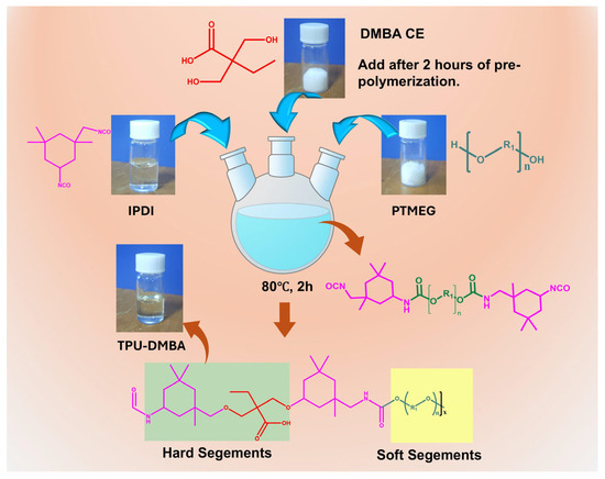
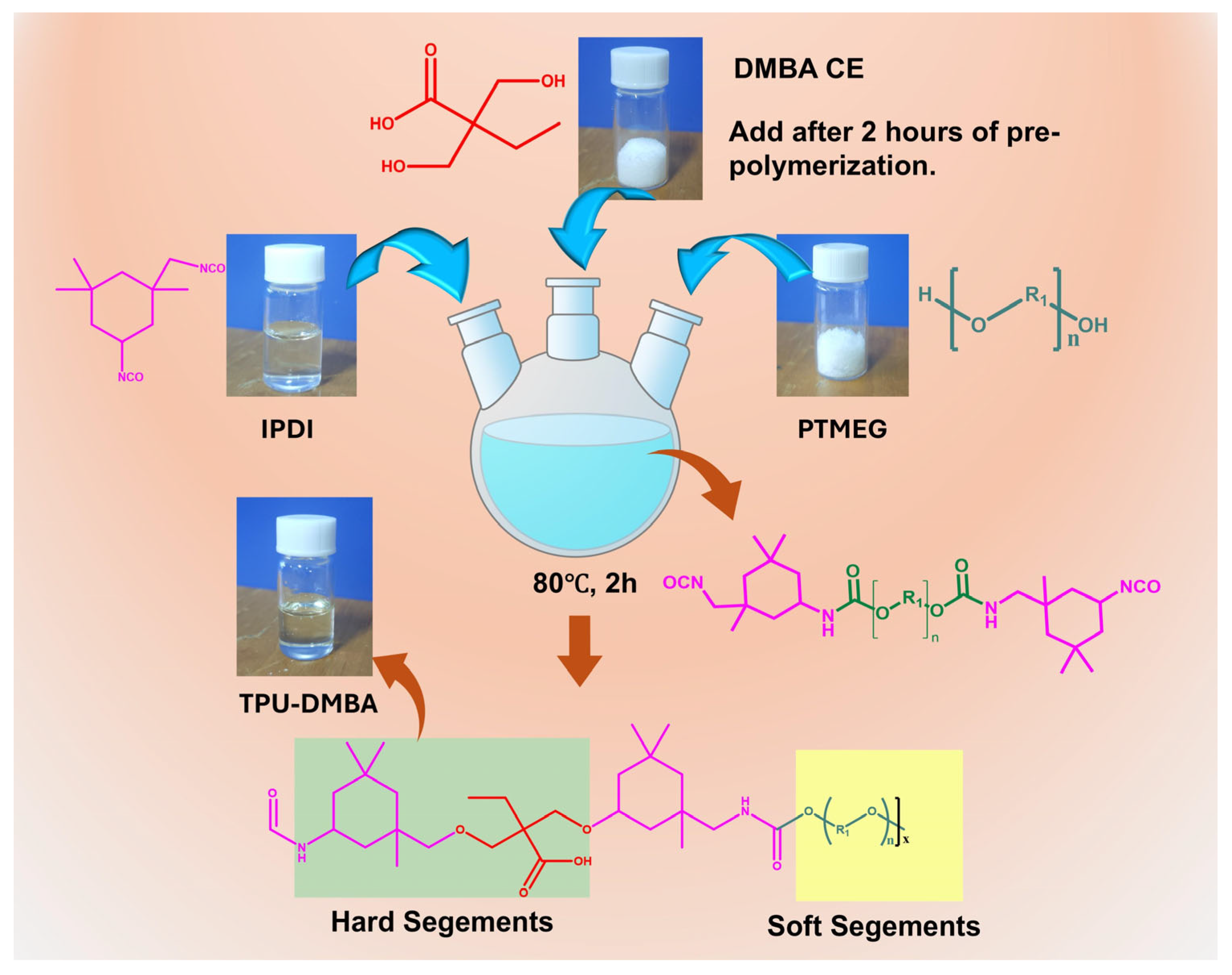
Figure 1 illustrates the molecular design and synthesis route of the TPU-DMBA polymer, where IPDI, PTMEG, and DMBA are used as raw materials to synthesize the functional anionic polyurethane.
Figure 1.
Design and synthetic route of the TPU-DMBA polymer.
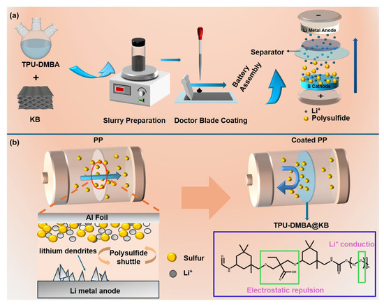
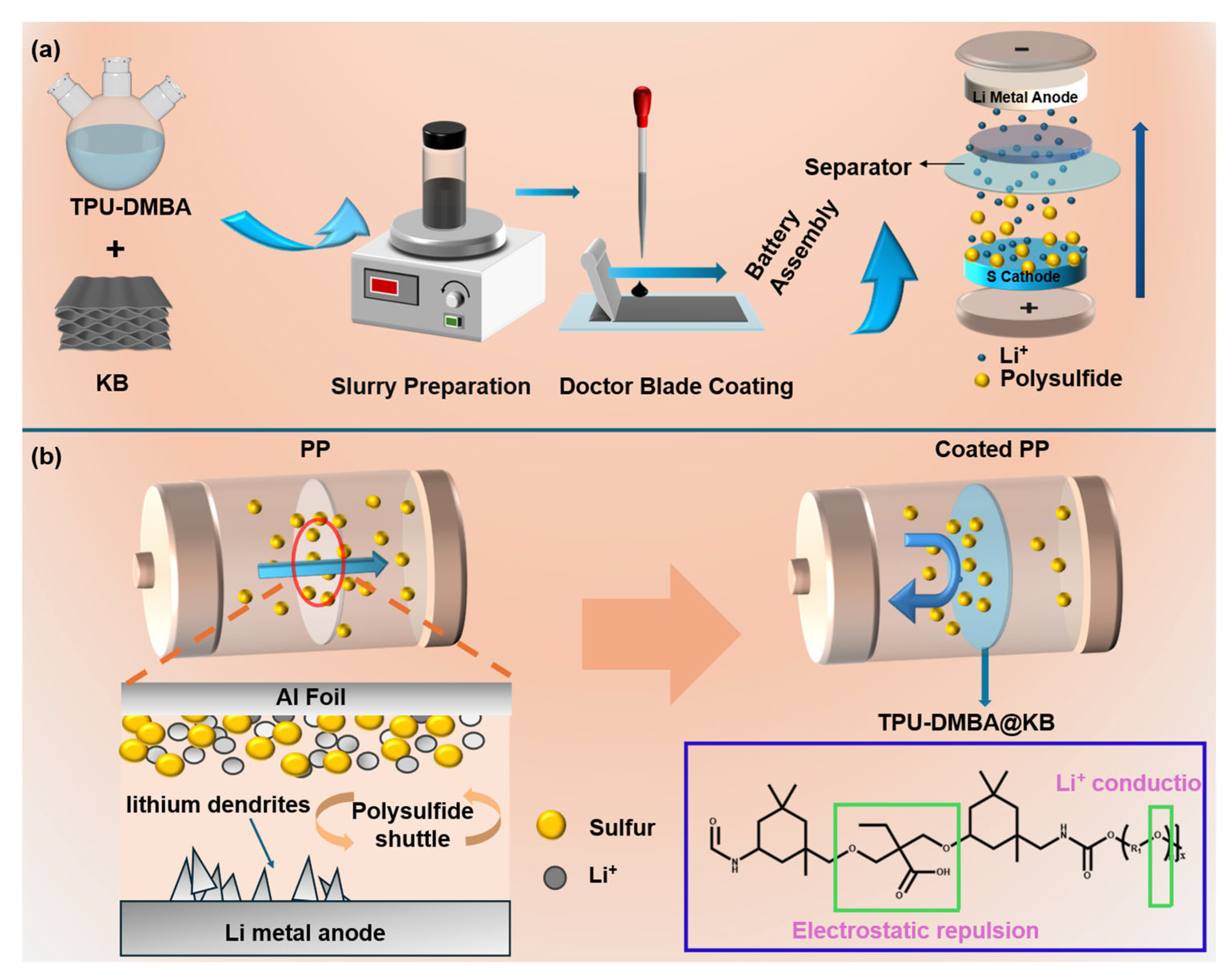
Figure 2a illustrates the fabrication process of the TPU-DMBA@KB-modified separator. TPU-DMBA and KB, as functional coating materials, are homogenized into a uniformly dispersed composite slurry, which is then evenly coated onto a PP separator using a doctor blade technique, forming a TPU-DMBA@KB functional layer of approximately 5 μm in thickness. The resulting modified separator is used for cell assembly. In the cell configuration, the modified separator is placed between the sulfur cathode and the lithium anode, with the TPU-DMBA@KB coating layer facing the cathode side. Figure 2b demonstrates the working principle of the TPU-DMBA@KB material in limiting polysulfide migration and enhancing the mechanical properties of the separator. The negatively charged carboxyl groups in the coating layer effectively hinder the migration of negatively charged polysulfides toward the anode via electrostatic repulsion. The flexible polymer backbone improves the mechanical robustness of the separator and inhibits dendrite penetration. Meanwhile, the conductive carbon network facilitates rapid Li+ transport, restricts polysulfide crossover, and confines active species on the cathode side, enabling their reactivation and reuse, thereby delaying battery capacity decay.
Figure 2.
(a) Schematic illustration of the fabrication process of the TPU-DMBA@KB-modified separator; (b) Schematic diagram of the mechanism for restricting polysulfides by the TPU-DMBA@KB-modified separator.
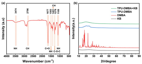
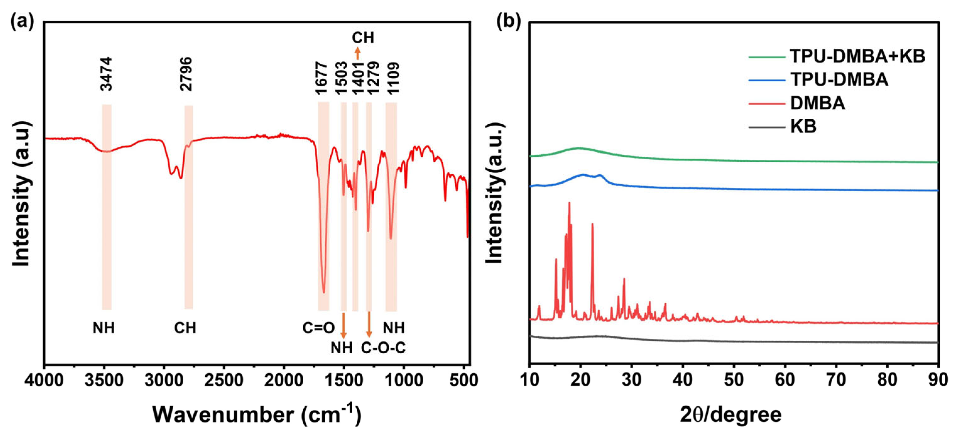
To verify the successful synthesis of TPU-DMBA and the structural characteristics of the composite membrane, Fourier transform infrared spectroscopy (FTIR, Thermo Fisher Scientific, Waltham, MA, USA) and X-ray diffraction (XRD, Rigaku Corporation, Akishima, Tokyo, Japan) were employed for characterization. As shown in Figure 3a, the FTIR spectrum exhibits an absorption band at 3474 cm−1 attributable to the N–H stretching vibration of urethane groups, a strong band at 1677 cm−1 corresponding to the C=O stretching vibration, and a band at 1503 cm−1 assigned to the amide II band (N–H in-plane bending coupled with C–N stretching). The absence of an isocyanate (–NCO) characteristic peak near 2270 cm−1 indicates complete polymerization. The C–O–C stretching vibration at 1109 cm−1 confirms the presence of the polyether soft segment, while the bands at 1401 and 1279 cm−1 are associated with the carboxyl groups introduced by DMBA, demonstrating that the anionic functional groups have been successfully incorporated into the polyurethane chains. The XRD patterns (Figure 3b) show that the raw DMBA is crystalline, exhibiting multiple sharp diffraction peaks. In contrast, TPU-DMBA displays only a broad diffuse peak at approximately 2θ = 20°, characteristic of an amorphous polymer, with no diffraction peaks corresponding to DMBA, indicating the absence of residual raw material and ruling out simple physical mixing. Furthermore, the XRD pattern of the TPU-DMBA@KB composite membrane shows no obvious characteristic diffraction peaks of KB, suggesting that KB is uniformly dispersed in the polymer matrix without forming distinct crystalline domains.
Figure 3.
Structural characterization of the TPU-DMBA@KB composite. (a) FTIR spectrum of TPU-DMBA; (b) XRD patterns of KB, DMBA, TPU-DMBA, and TPU-DMBA@KB.
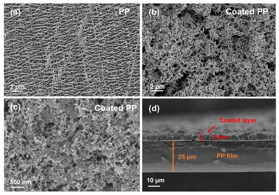
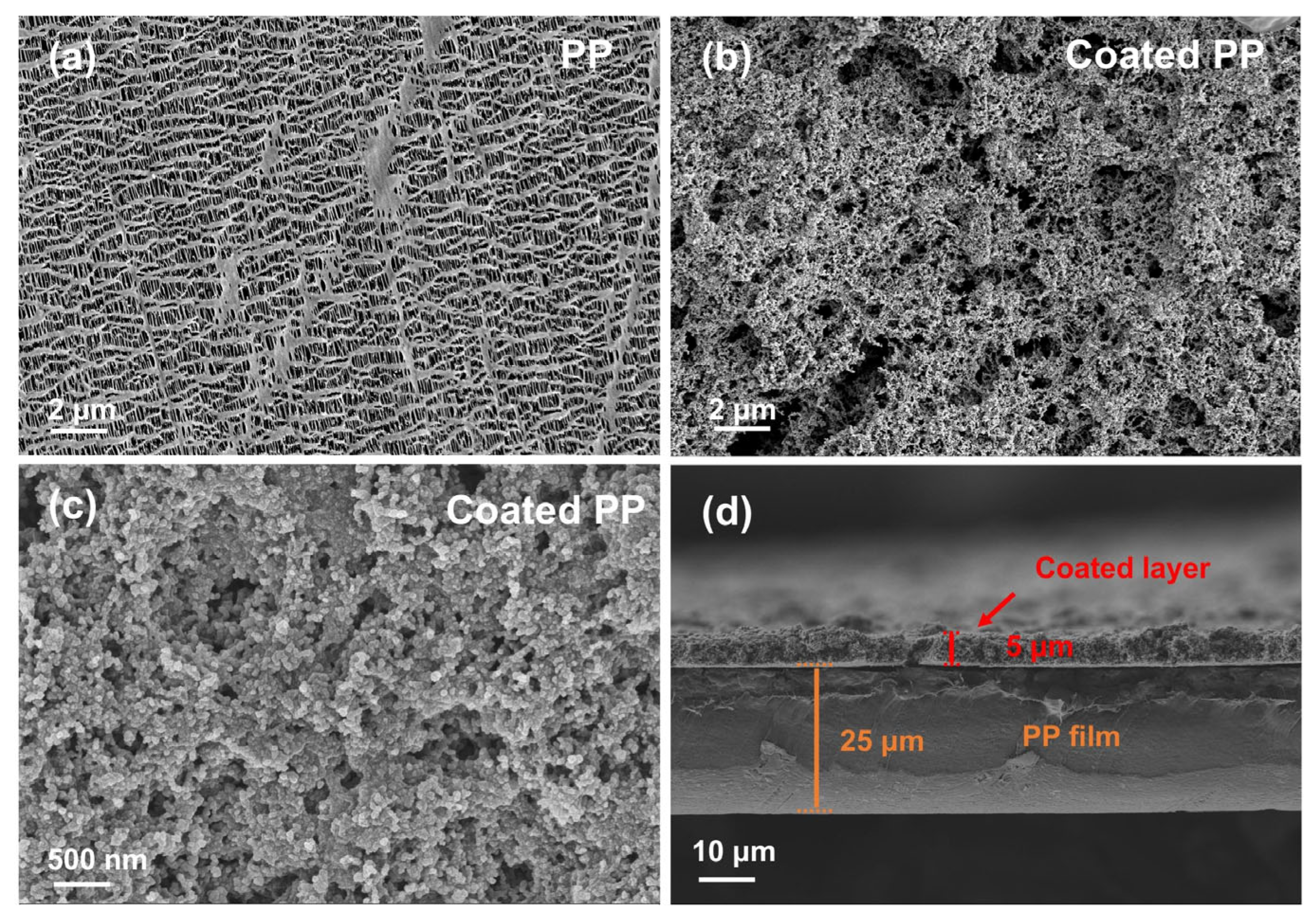
To observe the effect of the TPU-DMBA@KB modified material on the microstructure of the separator, the morphologies and coating thickness of the pristine PP separator and the modified separator were characterized by SEM (GeminiSEM 300, Carl Zeiss AG, Oberkochen, Germany). Figure 4a shows the surface structure of the pristine PP separator, which exhibits an uneven fishing net-like pore size distribution. Polysulfides can easily pass through the PP separator to the other side, leading to active material loss and deteriorated battery performance [26]. Figure 4b,c display the surface morphologies of the modified separator at different magnifications. After coating with the functional material, a rich porous structure is formed, which increases the specific surface area of the separator and fully exposes the functional groups (carboxyl, ether bonds, etc.) in the modifying material, thereby enhancing the restriction of polysulfides at multiple levels [27]. Furthermore, Figure 4d shows that the coating thickness is approximately 5 μm. Such thickness does not significantly increase the overall mass of the battery and thus will not cause substantial loss in energy density.
Figure 4.
(a–d) SEM images of the pristine PP separator and the TPU-DMBA@KB-modified separator.
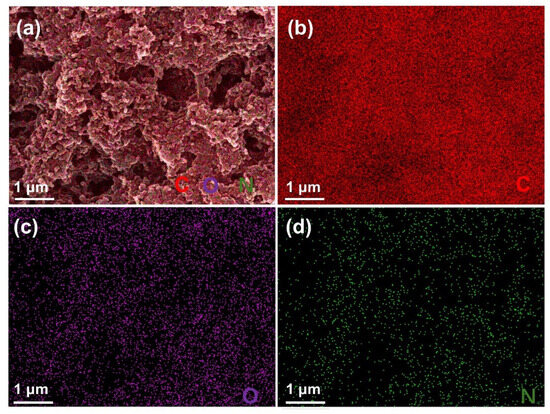
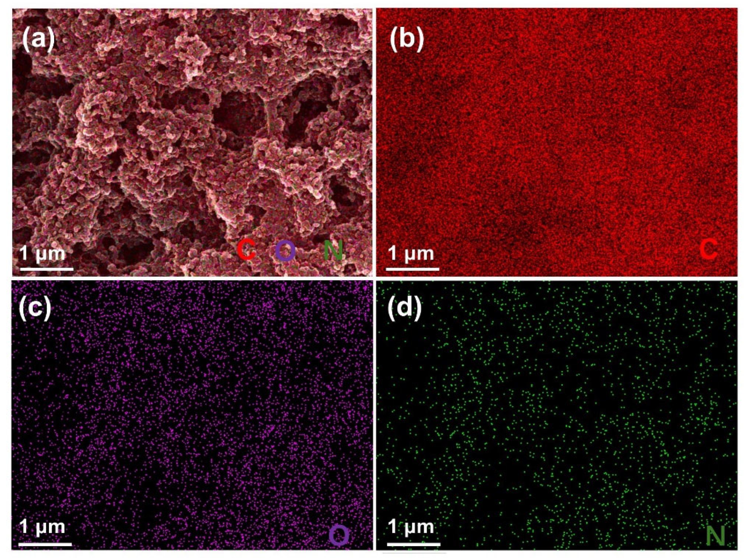
To evaluate the uniformity and elemental distribution of the TPU-DMBA@KB modification layer, the surface elemental distribution of the separator was characterized. Figure 5a presents the overall elemental mapping image of the modified separator surface, showing that all elements of the coating are uniformly distributed on the separator surface without obvious agglomeration. Figure 5b–d show the elemental mappings of C, O, and N, respectively. The C, O, and N elements are uniformly distributed within the selected area, with no obvious enrichment or deficiency. The uniform elemental distribution confirms the good composite and dispersion of TPU-DMBA and KB on the separator surface, providing a uniform functional interface for polysulfide restriction and lithium-ion transport.
Figure 5.
(a–d) Elemental distribution maps of the TPU-DMBA@KB-modified separator surface.
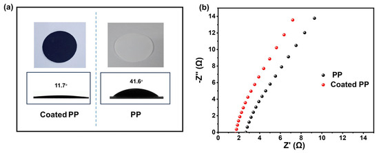
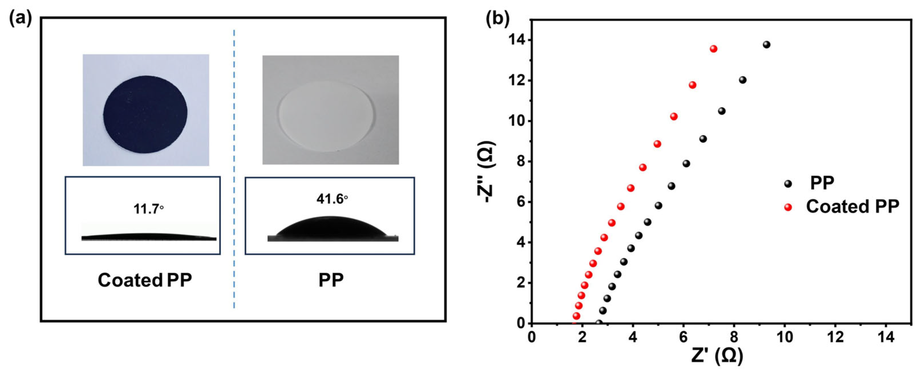
To investigate the improvement in electrolyte affinity imparted by the modified material, contact angle measurements were performed on the pristine PP separator and the TPU-DMBA@KB-modified separator using the electrolyte. As shown in Figure 6a, the PP separator exhibits a contact angle of 41.6°, whereas the TPU-DMBA@KB-modified separator shows a significantly lower contact angle of 11.7°. Compared with the PP separator, the modified separator demonstrates much better electrolyte wettability. This is because the pristine PP separator has a non-polar composition and low surface tension, resulting in a relatively large contact angle with the polar electrolyte. In contrast, the hydrophilic carboxyl groups derived from the modifier and the affinity of the carbon material endow the modified separator with superior wettability. Compared with the PP separator, the electrolyte can more easily penetrate the modified separator, which facilitates rapid Li+ transport during charge and discharge.
Figure 6.
(a) Electrolyte contact angles of the pristine PP separator and the TPU-DMBA@KB-modified separator; (b) EIS spectra of stainless steel symmetric cells assembled with the two separators.
The ionic conductivity of the separator is closely related to its electrochemical performance. Figure 6b presents the EIS spectra of stainless steel/separator/stainless steel symmetric cells, from which the ionic conductivities of the different separators were estimated. The TPU-DMBA@KB-coated separator exhibits an ionic conductivity of 0.88 × 10⁻³ S cm−1, which is higher than that of the pristine PP separator (0.48 × 10⁻³ S cm−1), indicating that the modified separator is more favorable for Li+ migration.
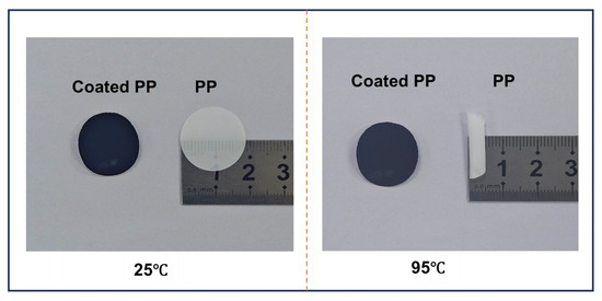
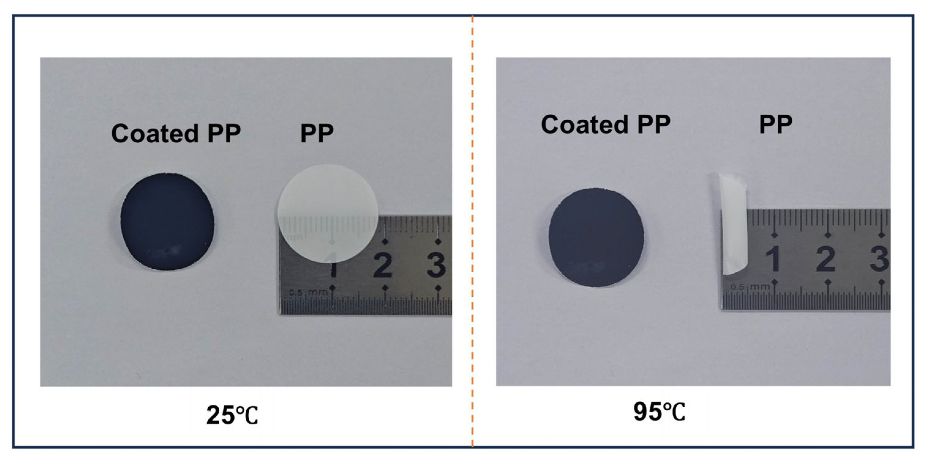
To investigate the effect of the TPU-DMBA@KB modification layer on the thermal stability of the separator, thermal stability tests were conducted. The pristine PP separator and the TPU-DMBA@KB-modified separator were placed in an oven and heated from 25 °C to 95 °C, and the dimensional changes in the separators were observed. As shown in Figure 7, the PP separator exhibited significant curling and edge warping at 95 °C, whereas the TPU-DMBA@KB-modified separator remained flat and showed no obvious shrinkage or deformation. This result indicates that the TPU-DMBA@KB coating significantly improves the thermal stability of the separator, which can be mainly attributed to the polymer network structure and its composite effect with KB, effectively suppressing the thermal shrinkage of the polypropylene substrate at elevated temperatures and reducing the risk of internal short circuits under abnormal temperature rise conditions.
Figure 7.
Thermal stability test: photographs of the pristine PP separator and the TPU-DMBA@KB-modified separator after heating from 25 °C to 95 °C.
In summary, the TPU-DMBA@KB-modified separator exhibits significant advantages in both morphology and functional properties. The TPU-DMBA@KB modification layer not only provides a uniform functional interface for polysulfide confinement and lithium-ion transport but also enhances the thermal stability of the separator, thereby laying a foundation for the optimization of electrochemical performance.
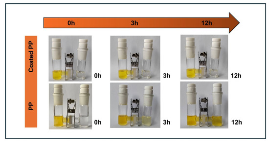
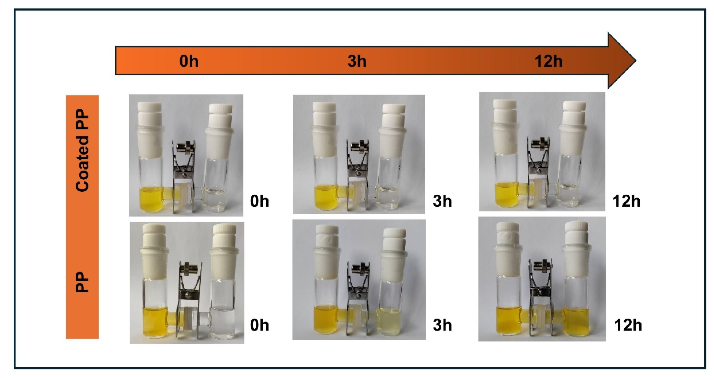
To evaluate the ability of the TPU-DMBA@KB-modified separator to block polysulfide diffusion, an H-type diffusion cell was employed for polysulfide permeation tests [28]. Figure 8 shows the dynamic permeation process of polysulfides through the separators. The pristine PP separator and the modified separator were placed in the H-type cell, with the left compartment containing the polysulfide electrolyte. The diffusion of polysulfides to the right compartment was observed over time. At the initial time (0 h), no obvious color change was observed in either side. After 3 h, the right side of the PP separator turned distinctly yellowish-brown, indicating substantial diffusion of polysulfides across the separator, whereas the right side of the polymer-modified separator remained clear and transparent. After 12 h, the color on the PP side further deepened, indicating intensified polysulfide diffusion. In contrast, only a very faint color change was observed on the side of the modified separator, demonstrating its excellent blocking capability against polysulfides. This result indicates that the anionic polymer modification layer can effectively suppress the transmembrane diffusion of polysulfides. The underlying mechanism can be attributed to the physical adsorption of the carbon material and the electrostatic repulsion between the anionic functional groups introduced into the polymer backbone and the negatively charged polysulfide anions, thereby effectively inhibiting the diffusion of sulfide species.
Figure 8.
H-type diffusion cell permeation test of polysulfides through the pristine PP separator and the TPU-DMBA@KB-modified separator.
3.2. Electrochemical Performance Analysis of the TPU-DMBA@KB-Modified Separator
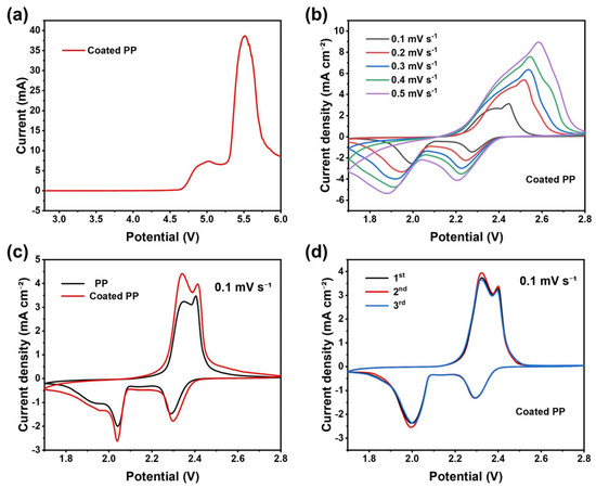
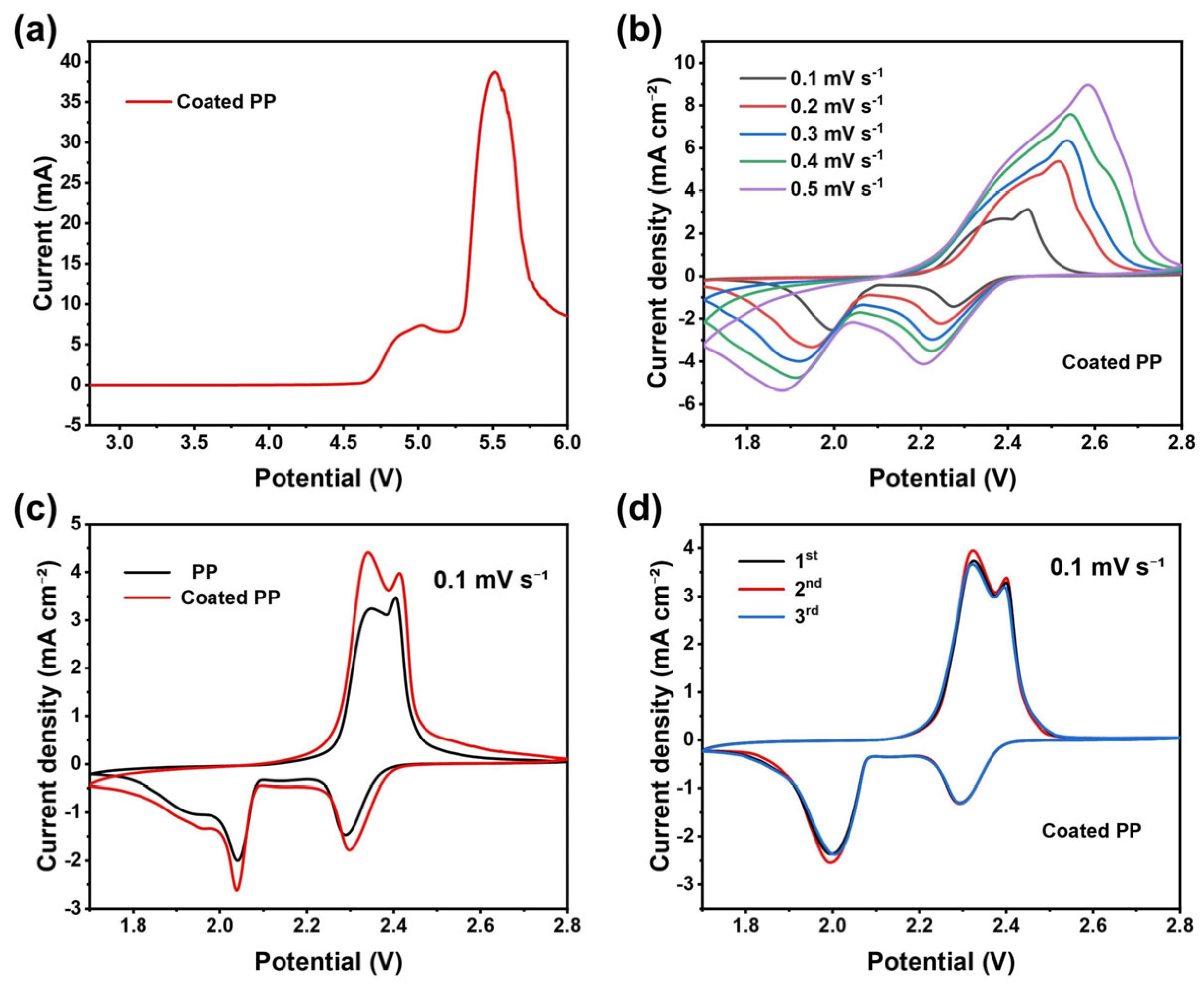
The electrochemical stability window of the TPU-DMBA@KB-modified separator was evaluated by linear sweep voltammetry (LSV) from the open-circuit potential (approximately 2.8 V) toward higher potentials. As shown in Figure 9a, an obvious oxidation peak appears at 4.7 V, corresponding to the irreversible oxidative decomposition of the electrolyte and polymer components. This decomposition potential is far above the upper limit of the normal operating voltage of Li–S batteries (2.8 V), indicating that the TPU-DMBA@KB-modified separator possesses good electrochemical stability under practical working conditions without side reactions, thus meeting the requirements for high-safety Li–S battery separators.
Figure 9.
(a) LSV curve of the TPU-DMBA@KB-modified separator at a scan rate of 1 mV s−1. (b) CV curves of the TPU-DMBA@KB-modified separator at different scan rates. (c) CV curves of the TPU-DMBA@KB-modified separator and the pristine PP separator at 0.1 mV s−1. (d) Three consecutive CV cycles of the TPU-DMBA@KB-modified separator at 0.1 mV s−1.
To investigate the effect of the modified separator coating on the electrochemical behavior of Li–S batteries, cyclic voltammetry (CV) tests were performed on cells assembled with the TPU-DMBA@KB-modified separator at different scan rates, and the results are presented in Figure 9b. The cell exhibits typical CV features of Li–S batteries [29,30]: a first reduction peak near 2.3 V corresponding to the reduction of long-chain lithium polysulfides to Li2S4, and a second reduction peak near 2.0 V corresponding to the further reduction of Li2S4 to solid Li2S2 and Li2S. During the anodic scan, two oxidation peaks (at about 2.3 V and 2.4 V) merge into a single broad peak in the range of 2.3–2.5 V, which is attributed to the successive oxidation of Li2S4 and Li2S to elemental sulfur at similar potentials. These results indicate that the TPU-DMBA@KB-modified separator not only maintains the typical redox reaction pathway of Li–S batteries but also does not interfere with the fundamental electrochemical conversion of active species. The CV curves at different scan rates show similar shapes and consistent peak potential shifts with scan rate, demonstrating that the modification layer has good electrochemical stability and reaction kinetic compatibility, which lays a foundation for improved battery performance. As shown in Figure 9c, the CV curves of the cell assembled with the TPU-DMBA@KB-modified separator exhibit significantly higher peak current intensities and larger integrated areas compared to those of the cell with the pristine PP separator. This indicates that the modification layer effectively restricts polysulfide shuttling near the separator and promotes the redox reactions of active species on the cathode side, thereby enhancing the discharge capacity of the battery [31]. The increase in peak current can be mainly attributed to two factors: (i) the conductive network constructed by KB reduces electrode polarization and accelerates electron transport; (ii) the carboxyl groups in the polymer chain mitigate the interference of polysulfides on the reaction interface through electrostatic repulsion, while the coordination of ether bonds with lithium ions improves interfacial ionic transport kinetics. As shown in Figure 9d, the CV curves of the modified separator cell for three consecutive cycles almost completely overlap, with no obvious shifts in peak potentials or peak currents. This demonstrates that the TPU-DMBA@KB-modified separator possesses excellent reversibility and interfacial stability during continuous electrochemical cycling. The stable CV response further confirms that the modification layer effectively suppresses the irreversible shuttling loss of polysulfides and maintains the reversible conversion of active species on the cathode side, thereby providing a strong guarantee for the long cycle life of the battery [32].
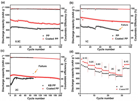
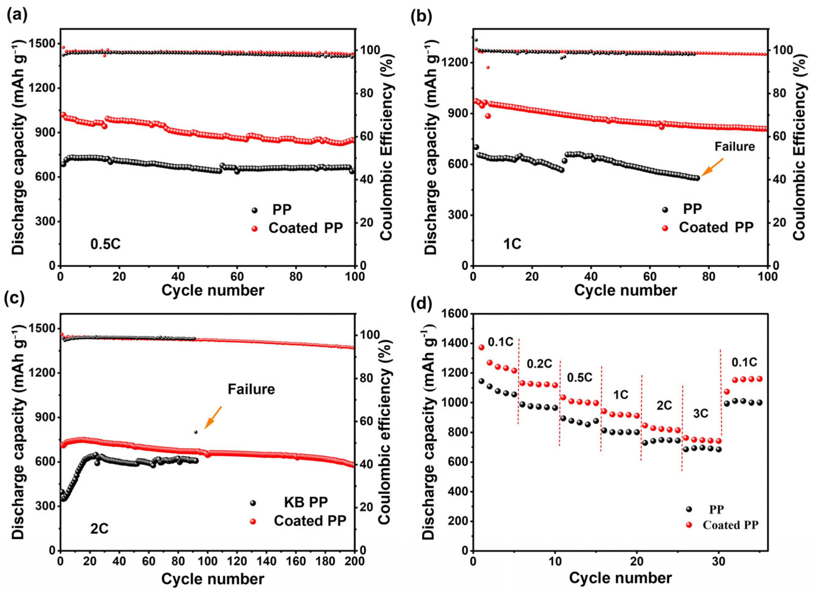
To systematically evaluate the rate capability and cycling stability of the TPU-DMBA@KB-modified separator, comparative tests were conducted on cells assembled with different separators at various rates. Figure 10a,b compare the discharge capacities of the TPU-DMBA@KB-modified separator and the pristine PP separator at 0.5 C and 1 C, respectively. The modified separator delivered discharge capacities of 1019.89 and 973.08 mAh g−1 at 0.5 C and 1 C, respectively, which are higher than those of the pristine PP separator under the same conditions. At 1 C, the PP separator cell failed after only 76 cycles, whereas the cell with the modified separator maintained superior electrochemical performance and stability throughout cycling.
Figure 10.
(a) Cycling performance of the TPU-DMBA@KB-modified separator and the pristine PP separator at 0.5 C; (b) Cycling performance at 1 C; (c) Cycling performance comparison of the KB-only modified separator and the TPU-DMBA@KB-modified separator at 2 C; (d) Rate capability of the TPU-DMBA@KB-modified separator and the pristine PP separator at various current densities.
To further elucidate the role of the carboxyl-containing anionic polymer, a control experiment was performed using a separator modified with only the carbon material (KB) without the polymer coating. Figure 10c compares the performance of the two separators at a high rate of 2 C. The TPU-DMBA@KB-modified separator delivered a discharge capacity of 714.46 mAh g−1 at 2 C. The KB-only modified separator exhibited poor cycling stability, failing after only 92 cycles with a Coulombic efficiency decay to 55.04%. In contrast, the TPU-DMBA@KB-modified separator (containing the carboxyl-rich anionic polymer coating) demonstrated excellent long-term performance. After 200 cycles, the capacity remains 577.93 mAh g−1, with a capacity retention of 80.89% and a Coulombic efficiency of 94.13%. This significant difference confirms that, at high rates, the electrostatic repulsion from –COO− groups plays a dominant role in suppressing polysulfide shuttling, whereas physical adsorption by porous carbon alone is insufficient to achieve the same effect. Figure 10d shows the discharge capacities at various rates (0.1 C, 0.2 C, 0.5 C, 1 C, 2 C, 3 C, and back to 0.1 C). At 0.1 C, the modified separator delivered a capacity of 1372.07 mAh g−1. Throughout the rate-switching protocol, the modified separator consistently exhibited higher discharge capacities, demonstrating that the cell assembled with this modified separator has excellent rate capability.
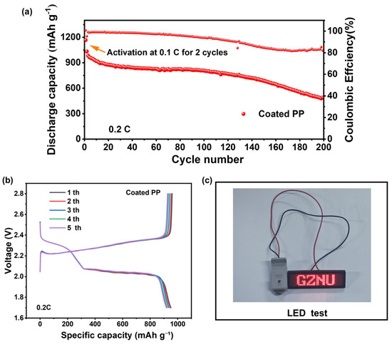
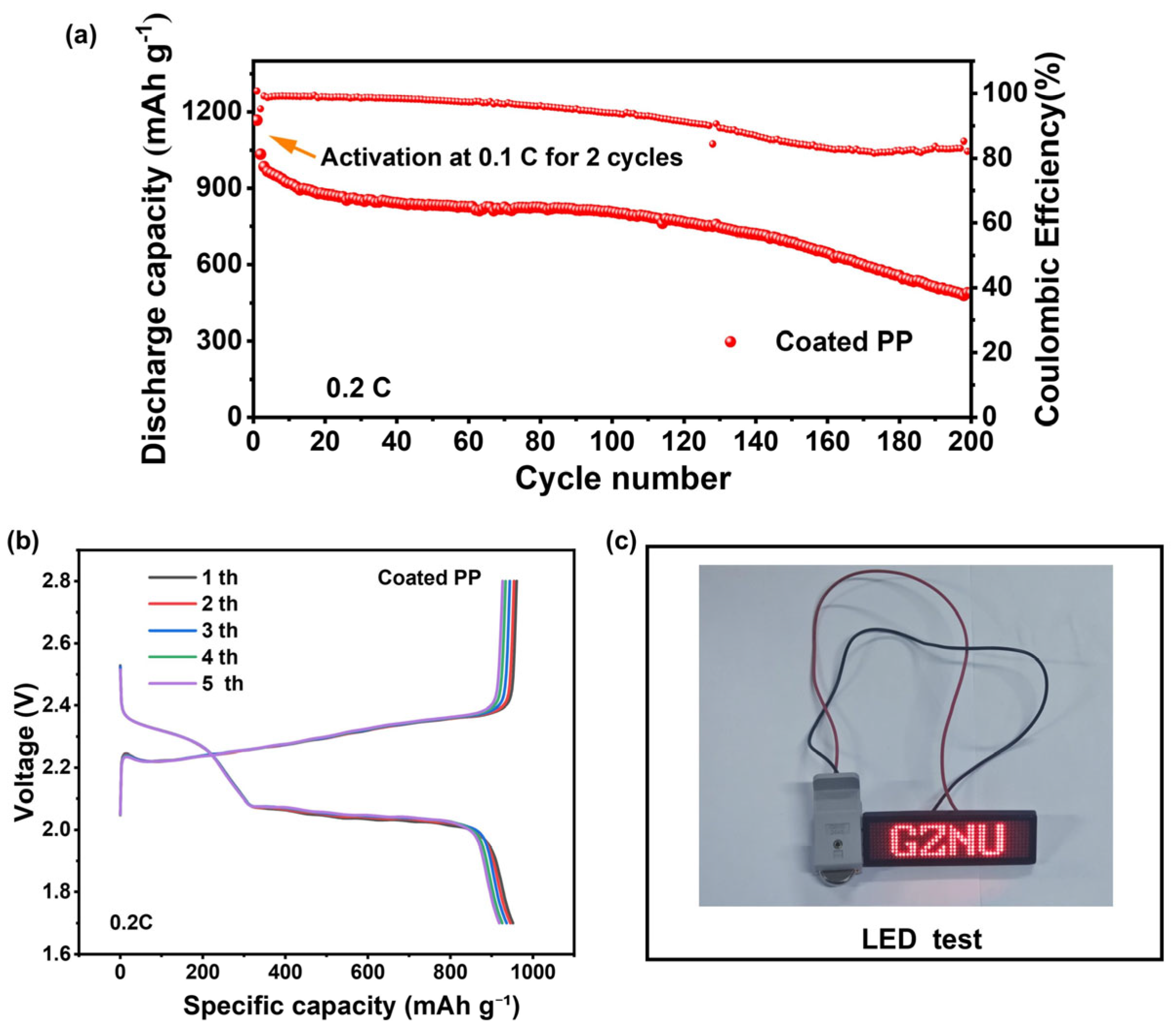
To further verify the practical application potential of the TPU-DMBA@KB-modified separator, the cycling performance of the TPU-DMBA@KB composite-modified separator was evaluated under high sulfur loading conditions. As shown in Figure 11a, after activation, the cell with the TPU-DMBA@KB-modified separator delivered a discharge capacity of 985.11 mAh g−1 at 0.2 C and maintained stable cycling for 200 cycles. Figure 11b presents the charge–discharge profiles at 0.2 C under high sulfur loading. Two typical discharge plateaus are still observed for the cell with the TPU-DMBA@KB-modified separator, and the plateau voltages remain stable without noticeable polarization increase, indicating that the modification layer effectively suppresses polysulfide shuttling and maintains favorable reaction kinetics even under high sulfur loading conditions. Figure 11c shows an optical photograph of an LED light powered by a Li–S battery assembled with the TPU-DMBA@KB-modified separator. After full activation, the battery stably powers the LED with no obvious decay in brightness. This result visually demonstrates that the battery system constructed by separator modification possesses low polarization resistance and favorable reaction kinetics, showing promising potential for application in energy storage devices.
Figure 11.
(a) Cycling performance of the TPU-DMBA@KB-modified separator at 0.2 C under high sulfur loading; (b) Five charge–discharge profiles at 0.2 C under high sulfur loading; (c) Optical photograph of an LED light powered by a Li–S battery assembled with the TPU-DMBA@KB-modified separator.
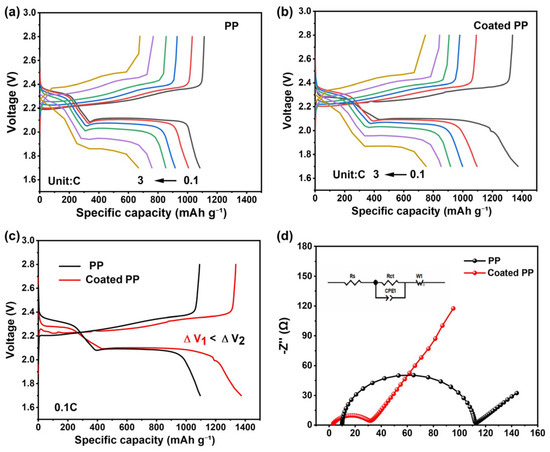
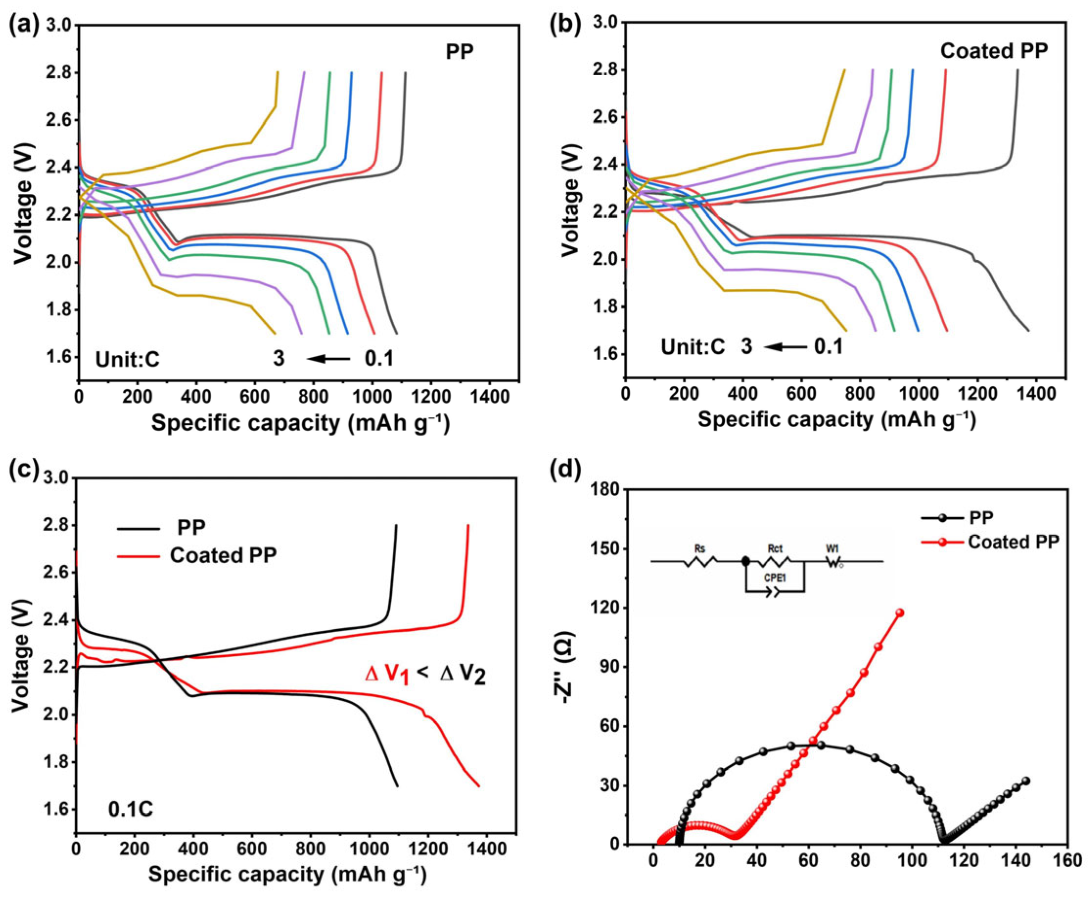
Galvanostatic charge–discharge tests were performed on coin cells assembled with the two types of separators at various rates (0.1 C, 0.2 C, 0.5 C, 1 C, 2 C, and 3 C). The resulting charge–discharge profiles are shown in Figure 12a,b. Compared with the pristine PP separator, the TPU-DMBA@KB-modified separator exhibits longer discharge plateaus at all rates, indicating that the modification layer effectively enhances the discharge capacity and improves the reaction kinetics of the battery. Figure 12c compares the polarization voltages of the two separators. The modified separator shows a much lower polarization potential and a higher discharge capacity than the PP separator, demonstrating that the modification layer effectively improves the electrochemical performance of the battery. With increasing specific discharge capacity, the voltage plateaus of both separators gradually decrease, which is consistent with the typical discharge characteristics of Li–S batteries. At the same current rate, the modified separator exhibits a higher discharge voltage plateau than the pristine PP separator, indicating lower polarization and superior reaction kinetics, which confirms the positive role of the modification layer in reducing battery polarization and enhancing active material utilization. To further investigate the underlying mechanism, the electrochemical impedance spectroscopy (EIS) data were fitted using a standard Randles equivalent circuit, and the results are shown in Figure 12d. Compared with the pristine PP separator (Rs = 10 Ω, Rct = 101.1 Ω), the TPU-DMBA@KB-modified separator shows significantly lower ohmic resistance (Rs = 2.5 Ω) and charge transfer resistance (Rct = 29.3 Ω). The decrease in Rs indicates enhanced ionic conductivity, while the reduction in Rct reflects improved interfacial charge transfer kinetics. These improvements are attributed to the enhanced electrolyte wettability and ionic conductivity provided by the carbon material, as well as the accelerated Li+ transport facilitated by the ether bonds in the polymer. The synergistic effect of these factors effectively reduces the internal resistance of the battery, confirming that the separator modification layer promotes ion transport and interfacial charge transfer, thereby improving the electrochemical performance of the battery.
Figure 12.
(a) Galvanostatic charge–discharge profiles of the PP separator at different rates; (b) Charge–discharge profiles of the TPU-DMBA@KB-modified separator at different rates; (c) Comparison of polarization voltages of the two separators; (d) EIS spectra of the PP separator and the TPU-DMBA@KB-modified separator before cycling (inset: corresponding equivalent circuit).
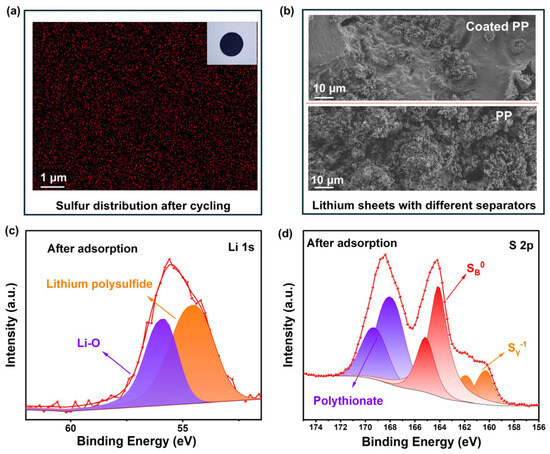
Figure 13a shows SEM images of the lithium anode surfaces after 100 cycles for the pristine PP separator and the TPU-DMBA@KB-modified separator. It can be observed from the SEM images that the lithium anode surface in the cell with the PP separator is rough and uneven, with obvious cracks and irregular deposits. This is mainly attributed to the continuous side reactions between lithium metal and the electrolyte, as well as the interfacial corrosion and accumulation of “dead lithium” caused by the shuttling of soluble polysulfides to the anode side. In contrast, the lithium anode surface in the cell with the TPU-DMBA@KB-modified separator is relatively smooth and dense, with no obvious dendrite growth or corrosion pits. This comparison demonstrates that the TPU-DMBA@KB modification layer effectively suppresses the shuttling behavior of polysulfides, significantly alleviates the interfacial degradation of the lithium anode, and thereby improves the cycling stability and safety of the battery.
Figure 13.
(a) SEM images of the lithium anode surfaces after 100 cycles for the pristine PP separator and the TPU-DMBA@KB-modified separator. (b) Sulfur element distribution (EDS mapping) on the separator surface after cycling (inset: digital photograph of the coating after cycling). (c,d) High-resolution XPS spectra of the TPU-DMBA@KB composite after polysulfide adsorption: (c) S 2p spectrum, (d) Li 1s spectrum.
Figure 13b presents the sulfur element distribution on the separator surface after cycling. Sulfur is uniformly distributed on the surface of the modified separator, with no obvious local enrichment or agglomeration. This indicates that the TPU-DMBA@KB modification layer effectively inhibits polysulfide shuttling during cycling, achieving efficient anchoring and uniform deposition of active sulfur species on the cathode side of the separator, thereby providing critical structural support for excellent long-term cycling stability. The inset shows a digital photograph of the coating after cycling; the coating remains tightly adhered to the PP substrate and maintains structural integrity even after prolonged exposure to the electrolyte, with no evident peeling or cracking. This further confirms that the polymer composite modification layer has good interfacial stability, effectively avoiding battery performance degradation caused by coating detachment. As shown in Figure 13c,d, to investigate the chemical interaction between the TPU-DMBA@KB composite and polysulfides, high-resolution X-ray photoelectron spectroscopy (XPS, model K-Alpha, Thermo Scientific, Waltham, MA, USA) analysis was performed on the samples after the adsorption test. The S 2p spectrum can be deconvoluted into three characteristic components. The peaks at 163–165 eV and 159–161 eV correspond to the bridging sulfur and terminal sulfur of the polysulfides, respectively, confirming the adsorption ability of the material [33,34]. In the Li 1s spectrum, two characteristic components corresponding to lithium polysulfide and the Li–O bond can be observed. The formation of the Li–O bond indicates that the Li+ in the polysulfides undergoes chemical coordination with the oxygen-containing functional groups of TPU-DMBA, thereby effectively anchoring the soluble polysulfides.
3.3. Mechanical Property Analysis of the TPU-DMBA@KB-Modified Separator
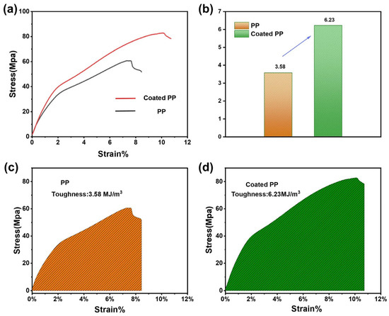
To evaluate the effect of polymer modification on the mechanical properties of the separator, tensile tests were conducted, and the results are shown in Figure 14a. Compared with the pristine PP separator, the TPU-DMBA@KB-modified separator exhibits a slight increase in tensile strength together with an improvement in elongation at break. This indicates that the polymer coating is successfully attached to the separator surface without compromising the extensibility of the PP substrate. The likely formation of a good interfacial bond between the coating and the substrate enables cooperative stress dissipation during stretching, delaying the initiation and propagation of macroscopic cracks. These mechanical characteristics, combining good flexibility with sufficient strength, help the separator maintain structural integrity during cell assembly and cycling, and suppress the penetration of lithium dendrites. Figure 14b Compared with the pristine PP separator, the TPU-DMBA@KB-modified separator shows a significant improvement. As shown in Figure 14c,d, the toughness value increases from 3.58 MJ m−3 for the pristine PP separator to 6.28 MJ m−3 for the TPU-DMBA@KB-modified separator. This significant improvement in toughness can be attributed to the effective dissipation of stress energy by the flexible polymer network structure and the hindering effect of rigid KB particles on crack propagation. Such high toughness further enhances the separator’s ability to resist external mechanical damage, providing a mechanical guarantee for improving the safety and cycling stability of lithium–sulfur batteries.
Figure 14.
(a) Tensile stress–strain curves of the pristine PP separator and the TPU-DMBA@KB-modified separator; (b) Comparison of toughness between the two separators. (c) Schematic diagram of the toughness (integral area under the stress–strain curve) for the pristine PP separator; (d) corresponding diagram for the TPU-DMBA@KB-modified separator.
4. Conclusions
To address the capacity decay caused by the loss of active materials due to polysulfide diffusion and the short-circuit issues caused by lithium dendrite penetration through the separator, this work designed a polymer material integrating both polysulfide repelling and mechanical reinforcement functions through molecular design, and applied it to modify the separator for lithium–sulfur batteries, thereby effectively enhancing the electrochemical performance. Specifically, the cell assembled with the TPU-DMBA@KB-modified separator delivered a discharge capacity of 973.08 mAh g−1 at 1 C, and retained 808.35 mAh g−1 after 100 cycles, corresponding to a capacity retention of approximately 83%, which is significantly higher than that of the PP separator (which failed after only 76 cycles). At 2 C, the separator modified with only carbon material (KB) exhibited poor cycling stability, failing after only 92 cycles with a Coulombic efficiency decay to 55.04%; in contrast, the TPU-DMBA@KB-modified separator (containing the anionic polymer coating) showed excellent long-term performance, maintaining a Coulombic efficiency of 94.13% after 200 cycles. This significant difference indicates that physical adsorption by porous carbon alone is insufficient to suppress polysulfide shuttling at high rates, especially under the high rate of 2 C. In comparison, the strong electrostatic repulsion originating from the –COO− groups provides long-term cycling stability. Meanwhile, the tensile strength of the modified separator increased by 30%, and its toughness increased from 3.58 to 6.28 MJ m−3. The enhanced mechanical properties help the separator maintain structural integrity during cycling and inhibit lithium dendrite penetration. By synergistically integrating electrostatic repulsion to confine polysulfides and mechanical reinforcement to suppress dendrite penetration, this work provides a feasible pathway for the design of high-performance separators for lithium–sulfur batteries.
Author Contributions
N.D.: Conceptualization, Validation, Methodology, Writing—original draft. Z.Z.: Data curation. Q.G.: Investigation. H.Z.: Methodology. H.W.: Investigation. R.L.: Writing—review and editing, Conceptualization. W.G.: Funding acquisition, Conceptualization. Z.Y.: Methodology; Writing—review and editing; Funding acquisition. All authors have read and agreed to the published version of the manuscript.
Funding
Research reported in this publication was supported by the National Natural Science Foundation of China (22561009), Basic Research Program Young Scientists Guidance Project of Guizhou Province [QN (2025) 182] and Advanced Functional Polymer Composite Materials Technology Innovation Leading Talent Workstation, Qian Ke He Platform KXJZ[2024]028.
Institutional Review Board Statement
Not applicable.
Informed Consent Statement
Not applicable.
Data Availability Statement
The original contributions presented in this study are included in the article. Further inquiries can be directed to the corresponding authors.
Conflicts of Interest
The authors declare that they have no known competing financial interests or personal relationships that could have appeared to influence the work reported in this paper.
References
- Park, G.-T.; Ryu, H.-H.; Park, N.-Y.; Lee, S.-B.; Sun, Y.-K. Single-crystal vs polycrystalline cathodes for lithium-ion batteries. Chem. Rev. 2025, 125, 9930–10000. [Google Scholar] [CrossRef] [Scilit]
- Xu, J.; Cai, X.; Cai, S.; Shao, Y.; Hu, C.; Lu, S.; Ding, S. High-energy lithium-ion batteries: Recent progress and a promising future in applications. Energy Environ. Mater. 2023, 6, e12450. [Google Scholar] [CrossRef] [Scilit]
- Celadon, A.; Sun, H.; Sun, S.; Zhang, G. Batteries for electric vehicles: Technical advancements, environmental challenges, and market perspectives. SusMat 2024, 4, e234. [Google Scholar] [CrossRef] [Scilit]
- Sawangphruk, M. New materials for lithium–sulfur batteries: Challenges and future directions. Chem. Commun. 2025, 61, 7770–7794. [Google Scholar] [CrossRef] [Scilit] [PubMed]
- Xiao, R.; Qu, Z.; Ren, J.; Wang, G.; Sun, Z.; Li, F. Current status and future prospects of solid-state lithium–sulfur batteries: A focus on reaction and interface engineering (Adv. Energy Mater. 8/2026). Adv. Energy Mater. 2026, 16, e70743. [Google Scholar] [CrossRef] [Scilit]
- Khan, F.M.N.U.; Rasul, M.G.; Sayem, A.S.M.; Mandal, N. Maximizing energy density of lithium-ion batteries for electric vehicles: A critical review. Energy Rep. 2023, 9, 11–21. [Google Scholar] [CrossRef] [Scilit]
- Song, H.; Münch, K.; Liu, X.; Shen, K.; Zhang, R.; Weintraut, T.; Yusim, Y.; Jiang, D.; Hong, X.; Meng, J.; et al. All-solid-state Li–S batteries with fast solid–solid sulfur reaction. Nature 2025, 637, 846–853. [Google Scholar] [CrossRef] [Scilit]
- Yao, W.; Xu, J.; Ma, L.; Lu, X.; Luo, D.; Qian, J.; Zhan, L.; Manke, I.; Yang, C.; Adelhelm, P.; et al. Recent progress for concurrent realization of shuttle-inhibition and dendrite-free lithium–sulfur batteries. Adv. Mater. 2023, 35, 2212116. [Google Scholar] [CrossRef] [Scilit]
- Evers, S.; Nazar, L.F. New approaches for high-energy density lithium–sulfur battery cathodes. Acc. Chem. Res. 2013, 46, 1135–1143. [Google Scholar] [CrossRef] [Scilit] [PubMed]
- Myrzakhmetov, B.; Rezaee, S.; Tuleuov, T.; Konarov, A. Additive-driven interfacial chemistry as the key to stabilizing lithium metal anodes. J. Energy Storage 2026, 146, 120171. [Google Scholar] [CrossRef] [Scilit]
- Manthiram, A.; Yu, X.; Wang, S. Lithium battery chemistries enabled by solid-state electrolytes. Nat. Rev. Mater. 2017, 2, 16103. [Google Scholar] [CrossRef] [Scilit]
- Wu, L.; Jin, Z.; Xie, X.; Lian, F.; Lu, J.; Wang, W. Lithium-reinforced polyoxometalate as effective catalytic interlayer for high-sulfur-loading and long-life lithium-sulfur batteries. Energy Storage Mater. 2025, 77, 104167. [Google Scholar] [CrossRef] [Scilit]
- Kim, S.H.; Yeon, J.S.; Kim, R.; Choi, K.M.; Park, H.S. A functional separator coated with sulfonated metal–organic framework/Nafion hybrids for Li–S batteries. J. Mater. Chem. A 2018, 6, 24971–24978. [Google Scholar] [CrossRef] [Scilit]
- He, J.; Chen, Y.; Manthiram, A. Vertical Co9S8 hollow nanowall arrays grown on a Celgard separator as a multifunctional polysulfide barrier for high-performance Li–S batteries. Energy Environ. Sci. 2018, 11, 2560–2568. [Google Scholar] [CrossRef] [Scilit]
- Zhao, M.; Li, B.-Q.; Zhang, X.-Q.; Huang, J.-Q.; Zhang, Q. A Perspective toward practical lithium–sulfur batteries. ACS Cent. Sci. 2020, 6, 1095–1104. [Google Scholar] [CrossRef] [Scilit]
- Deng, R.; Wang, M.; Yu, H.; Luo, S.; Li, J.; Chu, F.; Liu, B.; Wu, F. Recent advances and applications toward emerging lithium–sulfur batteries: Working principles and opportunities. Energy Environ. Mater. 2022, 5, 777–799. [Google Scholar] [CrossRef] [Scilit]
- Tanaka, A.; Mora, J.M.; Nagato, K.; Chuang, P.-Y.A. Static and dynamic rheo-impedance characterization of PEMFC catalyst inks. Electrochem. Commun. 2026, 187, 108165. [Google Scholar] [CrossRef] [Scilit]
- Wang, J.; Wang, H.; Jia, S.; Zhao, Q.; Zheng, Q.; Ma, Y.; Ma, T.; Li, X. Recent advances in inhibiting the shuttle effect of polysulfide in lithium-sulfur batteries. J. Energy Storage 2023, 72, 108372. [Google Scholar] [CrossRef] [Scilit]
- Kang, X.; He, T.; Zou, R.; Niu, S.; Ma, Y.; Zhu, F.; Ran, F. Size effect for inhibiting polysulfides shuttle in lithium-sulfur batteries. Small 2024, 20, 2306503. [Google Scholar] [CrossRef] [Scilit] [PubMed]
- Ye, H.; Li, Y. Room-temperature metal–sulfur batteries: What can we learn from lithium–sulfur? InfoMat 2022, 4, e12291. [Google Scholar] [CrossRef] [Scilit]
- Wang, J.; Yi, S.; Liu, J.; Sun, S.; Liu, Y.; Yang, D.; Xi, K.; Gao, G.; Abdelkader, A.; Yan, W.; et al. Suppressing the shuttle effect and dendrite growth in lithium–sulfur batteries. ACS Nano 2020, 14, 9819–9831. [Google Scholar] [CrossRef] [Scilit]
- Yang, B.; He, J.; Li, W.; Wang, Y.; Xu, P.; Feng, R.; Zhang, M. Functional modification and structural design of aramid nanofiber separators for lithium–sulfur batteries. ACS Appl. Nano Mater. 2025, 8, 19310–19321. [Google Scholar] [CrossRef] [Scilit]
- Liu, J.; Zhang, J.; Zhu, J.; Zhao, R.; Zhang, Y.; Ma, Y.; Li, C.; Zhang, H.; Chen, Y. A lithium sulfonylimide COF-modified separator for high-performance Li-S batteries. Nano Res. 2023, 16, 12601–12607. [Google Scholar] [CrossRef] [Scilit]
- Zhang, J.; Zhu, X.; Zhang, T.; Liu, X.; Elvis Cao, X.; Shen, J.; Shan, M.; Yang, H.; Shu, X.; Xu, G.; et al. Interfacial engineering assists dendrite-inhibiting separators for high-safety Li-S batteries. Chem. Eng. J. 2024, 496, 154031. [Google Scholar] [CrossRef] [Scilit]
- Wei, Q.; Wu, L.; Ye, Y.; Xiao, X.; Pei, M.; Lu, J.; Sun, H.; Wang, W.; Wang, B. Spatially engineered janus separator enables bidirectional regulation of sulfur electrochemistry and lithium deposition in high-energy-density lithium–sulfur pouch cells. Adv. Funct. Mater. 2026, 36, e21571. [Google Scholar] [CrossRef] [Scilit]
- Hu, S.; Yi, M.; Huang, X.; Wu, D.; Lu, B.; Wang, T.; Li, N.; Zhu, Z.; Liu, X.; Zhang, J. Cobalt-doped porphyrin-based porous organic polymer-modified separator for high-performance lithium–sulfur batteries. J. Mater. Chem. A 2021, 9, 2792–2805. [Google Scholar] [CrossRef] [Scilit]
- Balach, J.; Jaumann, T.; Klose, M.; Oswald, S.; Eckert, J.; Giebeler, L. Functional mesoporous carbon-coated separator for long-life, high-energy lithium–sulfur batteries. Adv. Funct. Mater. 2015, 25, 5285–5291. [Google Scholar] [CrossRef] [Scilit]
- Li, J.; Wu, X.; Jian, C.; Qiao, X.; Wan, F.; Wu, Z.; Zhong, B.; Chen, Y.; Guo, X. GO-CoNiP New composite material modified separator for long cycle lithium–sulfur batteries. Small 2024, 20, 2307912. [Google Scholar] [CrossRef] [Scilit] [PubMed]
- Xia, S.; Song, J.; Zhou, Q.; Liu, L.; Ye, J.; Wang, T.; Chen, Y.; Liu, Y.; Wu, Y.; van Ree, T. A Separator with double coatings of Li4Ti5O12 and conductive carbon for Li-S battery of good electrochemical performance. Adv. Sci. 2023, 10, 2301386. [Google Scholar] [CrossRef] [Scilit]
- Lin, Y.-C.; Wu, Y.-H.; Ting, J.-M.; Chung, S.-H. Stable lithium–sulfur cell separator with a high-entropy metal oxide modification. Energy Fuels 2023, 37, 15162–15169. [Google Scholar] [CrossRef] [Scilit]
- Dong, Q.; Zhao, X.; Ren, X.; Hong, W.; Li, R.; Gou, X.; Wang, T.; Li, C. Dopamine-modified separator anchoring polysulfides via electrostatic interaction for enhanced Lithium-sulfur batteries. J. Energy Storage 2025, 106, 114855. [Google Scholar] [CrossRef] [Scilit]
- Jia, B.; Sun, B.; Yu, H.; Yao, C.; Xie, W.; Xu, Y. Hydrogen sulfite ion functionalized cationic covalent organic framework nanosheets as a separator boosted the energy storage performance of Li–S batteries. J. Mater. Chem. A 2024, 12, 29205–29210. [Google Scholar] [CrossRef] [Scilit]
- Zuo, P.; Hua, J.; He, M.; Zhang, H.; Qian, Z.; Ma, Y.; Du, C.; Cheng, X.; Gao, Y.; Yin, G. Facilitating the redox reaction of polysulfides by an electrocatalytic layer-modified separator for lithium–sulfur batteries. J. Mater. Chem. A 2017, 5, 10936–10945. [Google Scholar] [CrossRef] [Scilit]
- Zhang, Y.; Cao, Y.; Fan, L.; Shi, G.; Zheng, T.; Liu, H.; Song, J.; Gao, G. Structure-defined viologen-polyoxometalate modified separator dominating endurable Li-S batteries by a synergistic adsorption-electrocatalysis mechanism. Chem. Eng. J. 2024, 482, 148991. [Google Scholar] [CrossRef] [Scilit]
Disclaimer/Publisher’s Note: The statements, opinions and data contained in all publications are solely those of the individual author(s) and contributor(s) and not of MDPI and/or the editor(s). MDPI and/or the editor(s) disclaim responsibility for any injury to people or property resulting from any ideas, methods, instructions or products referred to in the content. |
© 2026 by the authors. Licensee MDPI, Basel, Switzerland. This article is an open access article distributed under the terms and conditions of the Creative Commons Attribution (CC BY) license.