


Abstract
CoNiV medium-entropy alloy (MEA) composite coatings reinforced with 40 wt.% tungsten carbide (WC/W2C) particles were fabricated on carbon steel via laser cladding under nominal heat inputs ranging from 75 to 150 J/mm. The phase constituents and microstructural evolution were investigated, revealing that the coatings were primarily composed of an FCC matrix, retained WC/W2C particles, and in situ formed V-rich and VWC2 carbides. While the phase compositions remained generally consistent, the features of the reinforcement architecture varied with the extent of WC/W2C dissolution governed by laser heat inputs. At low heat inputs, limited particle dissolution yielded sparsely distributed in situ carbides, whereas excessive dissolution at high heat inputs promoted the agglomeration of dense and coarse carbides, driving the microhardness to peak at 570.5 HV0.5. However, the coating deposited at 150 J/mm exhibited compromised wear resistance due to the fragmentation and detachment of these coarse carbides, which intensified abrasive wear. In contrast, moderate dissolution at intermediate heat input (100 J/mm) facilitated the formation of fine in situ carbides in interparticle regions. This resulted in a homogeneous multiscale synergistic reinforcement microstructure that endowed the coating with optimal wear performance. By precisely controlling heat input to regulate in-situ precipitation, this study established a solid foundation for tailoring wear resistance and expanding the application of composite coatings.
1. Introduction
Carbon steels are indispensable in modern industrial applications. They are widely used in pipelines, mining equipment, and large-scale building structures owing to their excellent cost-effectiveness and balanced mechanical properties [1,2,3,4]. Despite these advantages, the relatively low surface hardness of carbon steels frequently leads to severe surface wear, which constitutes the primary failure mode in harsh service environments and thus compromises both economic efficiency and operational safety [5,6,7]. Consequently, the development of effective surface strengthening strategies is of paramount importance for prolonging the service life of these critical structural components [8].
Medium-entropy alloys (MEAs), which typically contain three to four principal elements in roughly equal atomic ratios [9], have emerged as promising candidates for high performance coatings owing to their special multi-element compositions and excellent mechanical properties [10]. To fabricate MEA coatings, various deposition techniques have been employed, such as cold spray, plasma spraying, and laser cladding [9,11,12,13]. Among these techniques, laser cladding has been widely adopted for component repair and surface enhancement owing to its low dilution rate, dense microstructure, and minimal heat-affected zone [14,15,16]. By precisely optimizing the laser process parameters (such as laser power and scanning speed), this method enables the in situ formation of reinforcing phases in the molten pool, offering a robust route for microstructure tailoring [17,18]. Among the MEAs, face-centered cubic (FCC) alloys, such as the CoNiV MEA, have been identified as attractive matrix materials owing to their inherent high ductility and outstanding plasticity [19]. These attributes provide a compliant matrix that can accommodate internal stresses. However, their relatively modest hardness often necessitates the addition of hard reinforcements to meet the demands of severe wear applications [20,21,22]. Common hard reinforcements in surface engineering include ceramic particles such as TiC, SiC, B4C, and Al2O3 [23,24,25]. Among these, tungsten carbide (WC/W2C) particles have been widely used owing to their superior hardness, high melting point, and excellent metallurgical compatibility with metallic matrices [26,27,28,29]. However, WC particles have certain limitations under high-temperature wear conditions [30]. In the context of medium- and high-entropy alloy (M/HEA) coatings, the incorporation of particles not only reduces the consumption of expensive principal elements but also markedly improves the tribological performance. This improvement is primarily attributed to the combined effects of dispersion strengthening, load sharing by retained particles, and second-phase hardening [31]. Moreover, the intense interaction between particles and the matrix during cladding promotes complex interfacial reactions that markedly influence the type and distribution of in situ synthesized carbides. Although the content and morphology of these in situ precipitates depend strongly on the dissolution degree of the particle, which is governed primarily by the heat input, the evolution of particle dissolution and the resulting characteristics of in situ precipitates in the CoNiV matrix remain unclear. This lack of understanding limits the ability to precisely regulate the microstructure and achieve an optimal balance between hardness and wear resistance.
In this study, CoNiV medium-entropy alloy composite coatings reinforced with 40 wt.% WC/W2C were fabricated. During the cladding process, the laser heat input was systematically varied to regulate the dissolution degree of particles and the resulting in situ precipitates. The effects of these precipitates on the microhardness and wear resistance of the coatings were evaluated. The present work aims to provide a strategic approach for tailoring the wear resistance of medium-entropy alloy coatings through the controlled regulation of in situ precipitates.
2. Materials and Methods
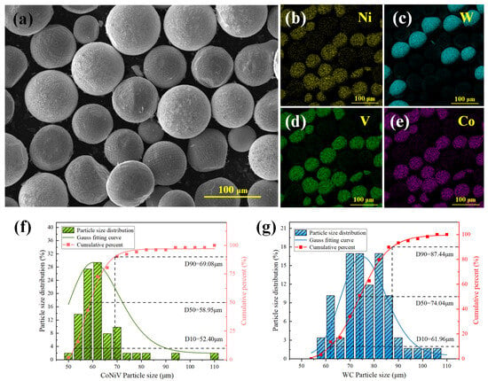
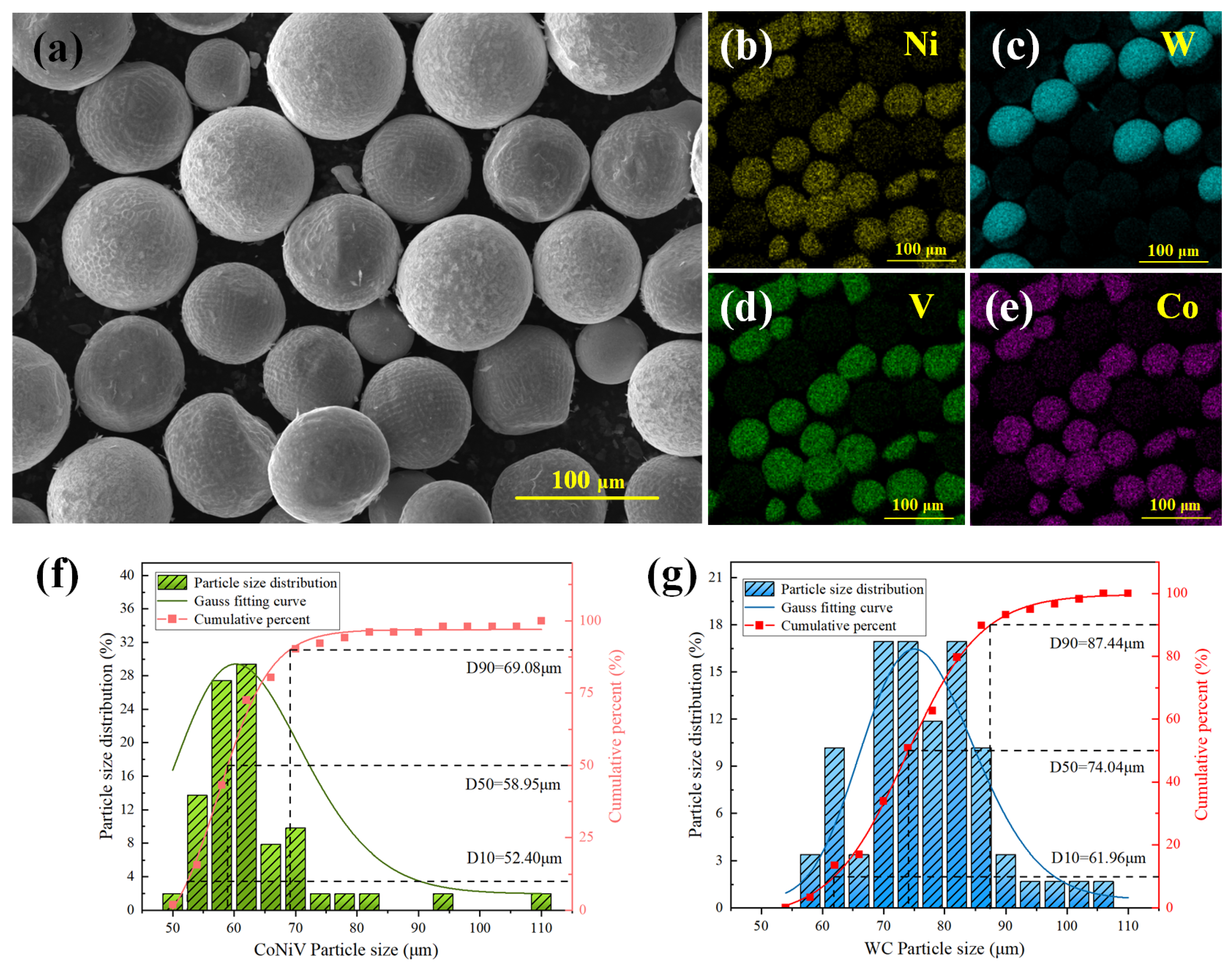
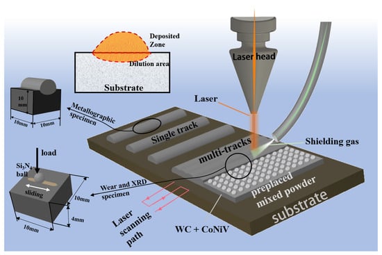
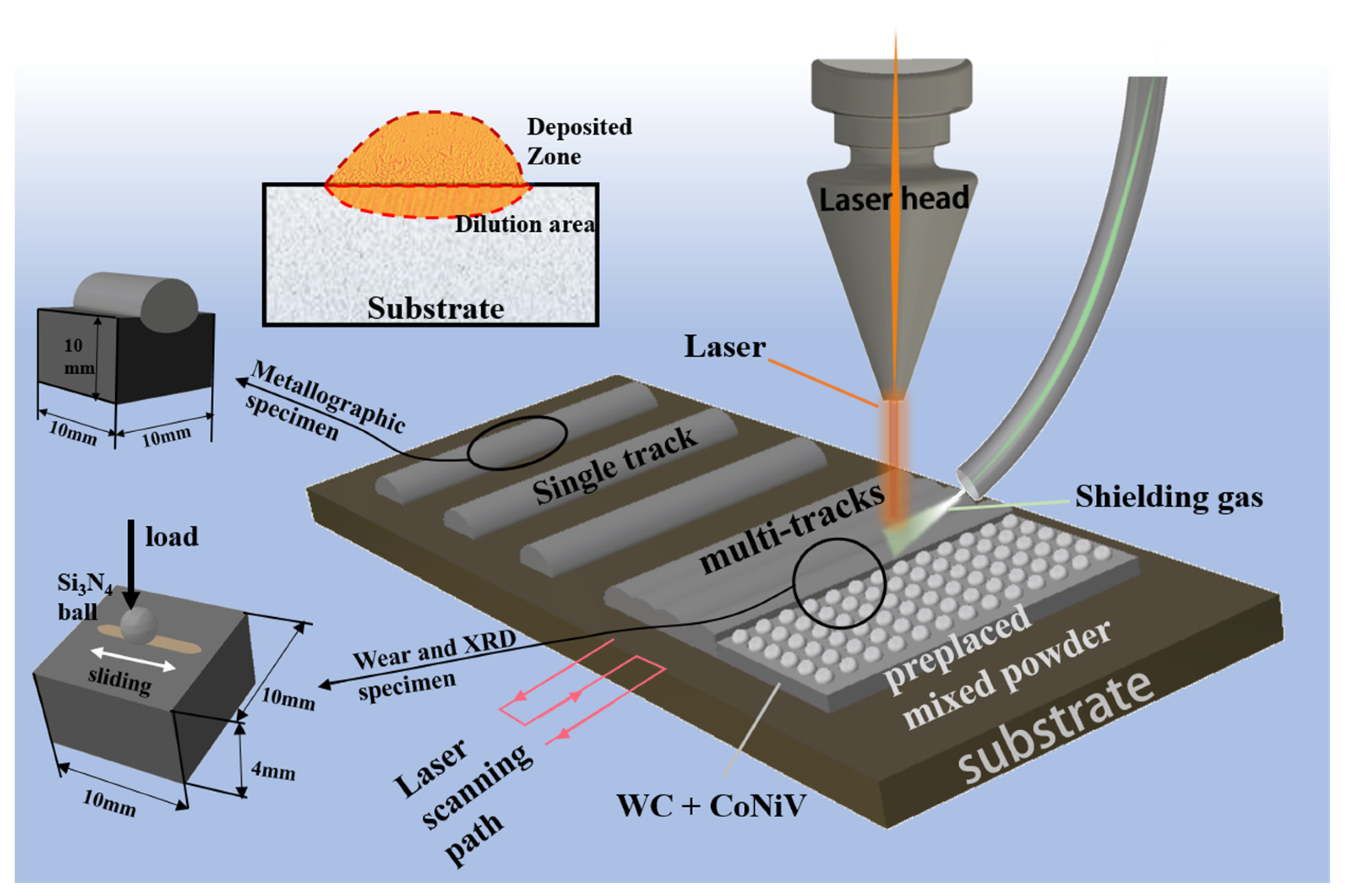
The feedstock materials for laser cladding consisted of spherical CoNiV medium-entropy alloy (MEA) powder with an average particle size of 60 μm and sintered spherical tungsten carbide (WC/W2C) particles ranging from 50 to 80 μm. The two powders were blended at a 60:40 weight ratio using a planetary ball mill (Deco, Changsha, China) at 400 rpm for 90 min. The blended powders were subsequently vacuum-dried at 80 °C for 8 h to remove residual moisture adsorbed from the ambient environment during powder handling and mixing. The morphology, elemental distribution, and particle size of the composite powders were characterized by scanning electron microscopy (SEM, Tescan Mira, Brno, Czech Republic). To ensure statistical reliability, the particle size distribution was determined by analyzing multiple representative SEM micrographs using ImageJ software (version 1.54r). The average particle sizes obtained from ImageJ analysis were found to be consistent with the results measured by a laser particle size analyzer (Mastersizer 3000, Malvern Panalytical, Malvern, UK). The typical morphology, elemental maps, and particle size distribution of the composite powders are shown in Figure 1. Q345 low-carbon steel plates with dimensions of 50 mm × 80 mm × 10 mm were used as the substrate material. Prior to the cladding process, the substrate surfaces were ground with sandpaper up to 800 grit, polished, and subsequently cleaned with alcohol. As schematically illustrated in Figure 2, the mixed powders were uniformly deposited onto the substrate by a pre-placed powder method with a thickness of approximately 0.5 mm. The pre-placed areas were 40 mm × 8 mm for single-track cladding and 40 mm × 40 mm for multi-track cladding.
Figure 1.
Characterization of the mixed CoNiV-WC composite powders: (a) SEM morphology; (b–e) EDS elemental mapping of Ni, W, V, and Co; (f) particle size distribution of CoNiV MEA powder; (g) particle size distribution of WC powder.
Figure 2.
Schematic of single-/multi-track cladding.
All experiments were conducted at room temperature (approximately 25 °C), without substrate preheating, using a high-power fiber laser system with a spot diameter of 4 mm under an argon shielding gas flow of 20 L/min. The same substrate geometry and clamping conditions were maintained throughout the study to ensure experimental repeatability. To investigate the effects of laser heat input on particle dissolution and microstructural evolution, the laser power (P) was kept constant at 1500 W, while the scanning speed (v) was adjusted to 20, 15, and 10 mm/s. The linear heat input (E) is defined as the energy input per unit length of the scan track. It is defined by E = P/v. In this study, E is used as a nominal process parameter rather than the effective heat input to the material system. Based on this formula, the E values for the three experimental groups were calculated as 75, 100, and 150 J/mm, respectively. For the multi-track coatings, an overlap rate of 60% was applied. The multi-track cladding was performed using a continuous zigzag scanning path, as schematically illustrated in Figure 2. Following the cladding process, the specimens were sectioned into specific dimensions for metallographic observation, XRD analysis, and wear testing, as shown schematically in Figure 2.
The cross-sections of the single-track coatings were ground with sandpaper (240#, 400#, 800#, and 1500#) and polished to a mirror finish. After etching with aqua regia for 30–50 s, the macro-morphology and internal microstructure of the coatings were examined using optical microscopy (OM, Olympus, Tokyo, Japan) and scanning electron microscopy (SEM, Tescan Mira, Brno, Czech Republic), and the elemental distribution was analyzed via energy-dispersive spectroscopy (EDS). The longitudinal sections of the multi-track composite coatings were ground and polished for phase identification and mechanical characterization. Phase constituents were identified by X-ray diffraction (D8 Advance, Bruker, Karlsruhe, Germany). To evaluate the mechanical properties, Vickers microhardness measurements were conducted on the polished sections using a microhardness tester (HV-1000, Sinowon, Dongguan, China) under a load of 500 gf and a dwell time of 15 s. The indentations deliberately avoided the ex situ WC/W2C particles to focus on the reinforced matrix. For each sample, the hardness was measured at six different locations, and the average values were calculated to ensure statistical reliability. To evaluate the tribological performance, dry sliding wear tests were conducted at room temperature using a tribometer (UMT-TriboLab, Bruker, Karlsruhe, Germany). The tests were performed under a normal load of 5 N, a reciprocating frequency of 4 Hz, and a test duration of 10 min, using a silicon nitride (Si3N4) ceramic ball of 6 mm diameter as the counterpart. The specific wear rates were quantified using the following formula of W = V/(F·L), where V is the wear volume, F is the applied normal load, and L is the total sliding distance.
3. Results and Discussion
3.1. Macro-Morphology and Phase Composition
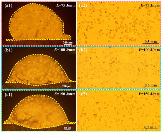
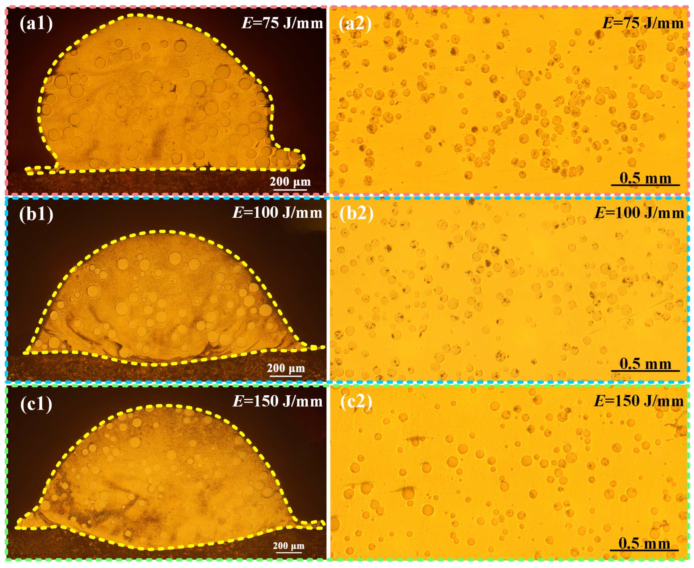
Figure 3 displays the cross-sections of single-track coatings and the longitudinal sections of multi-track composite coatings. Specifically, Figure 3(a1,a2), (b1,b2), and (c1,c2) corresponds to the coatings fabricated at linear heat inputs (E) of 75, 100, and 150 J/mm, respectively. As observed from the single-track morphologies, all coatings exhibit sound metallurgical bonding with the substrate. It can be observed that the linear heat input significantly influences the bead wettability and metallurgical interaction. At the lowest heat input of 75 J/mm (Figure 3(a1)), the coating exhibits a relatively low aspect ratio and a large wetting angle, with a measured dilution rate of only 1.02%, indicating limited melting of the substrate. As the heat input increases to 100 and 150 J/mm, the dilution rate rises markedly to 4.84% and 10.20%, respectively, resulting in improved wettability and a more robust metallurgical bond. Regarding the reinforcement phase, the WC/W2C particles are uniformly distributed throughout the matrix without noticeable gravitational settling. In the multi-track coating prepared at the lowest heat input (75 J/mm), no severe particle agglomeration occurs despite the limited molten pool fluidity caused by the lower energy density. In contrast, the WC/W2C particles are uniformly distributed in the other two coatings. Moreover, at the highest heat input (150 J/mm), the residual WC/W2C particles are markedly smaller than those in the other groups, indicating a greater degree of particle dissolution.
Figure 3.
Macro-morphology of the composite coatings: (a1–c1) cross-sections of the single-track coatings, (a2–c2) longitudinal sections of the multi-track coatings.
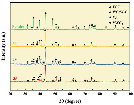
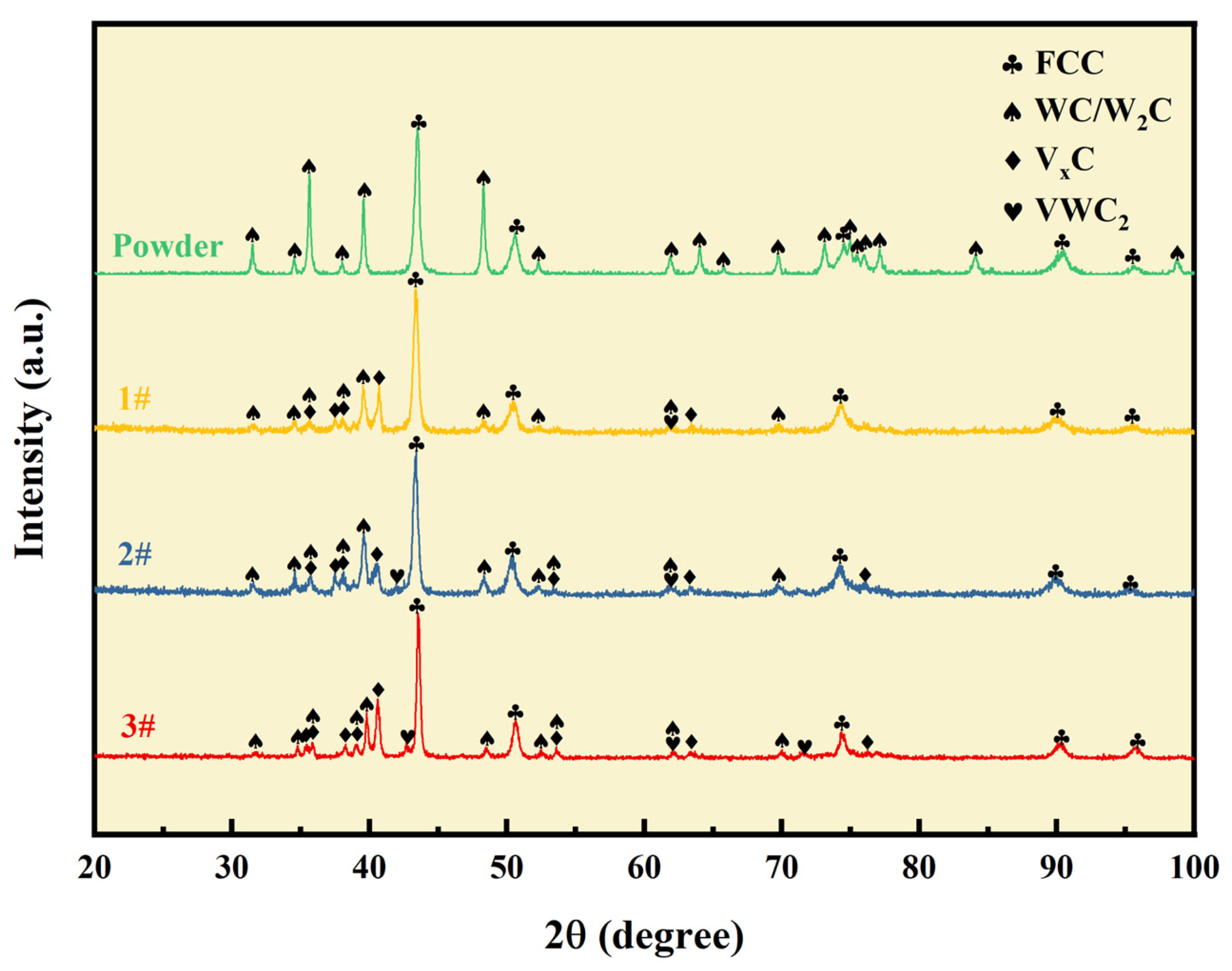
Figure 4 shows the X-ray diffraction (XRD) patterns of the mixed powders and the three CoNiV medium-entropy alloy composite coatings. The patterns labeled 1#, 2#, and 3# correspond to increasing linear heat input, respectively. The addition of WC/W2C particles has no significant influence on the crystal structure of the CoNiV matrix, the face-centered cubic (FCC) solid solution remaining the dominant phase in all three coatings. Additionally, these particles are not completely dissolved and are largely retained in the matrix, as evidenced by the presence of distinct WC and W2C diffraction peaks. These W2C peaks arise from two sources; the spherical sintered tungsten carbide particles inherently contain a WC/W2C eutectic structure, and partial decarburization of WC (2WC → W2C + C) occurs within the molten pool during the laser cladding process. Moreover, several peaks attributable to in situ carbide precipitates are observed, specifically V-rich carbides (denoted as VxC) and (V,W)-rich carbides.
Figure 4.
XRD patterns of the mixed powders and the WC/W2C-reinforced CoNiV medium-entropy alloy composite coatings fabricated at different linear heat inputs (E).
3.2. Microstructure Analysis
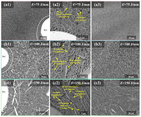
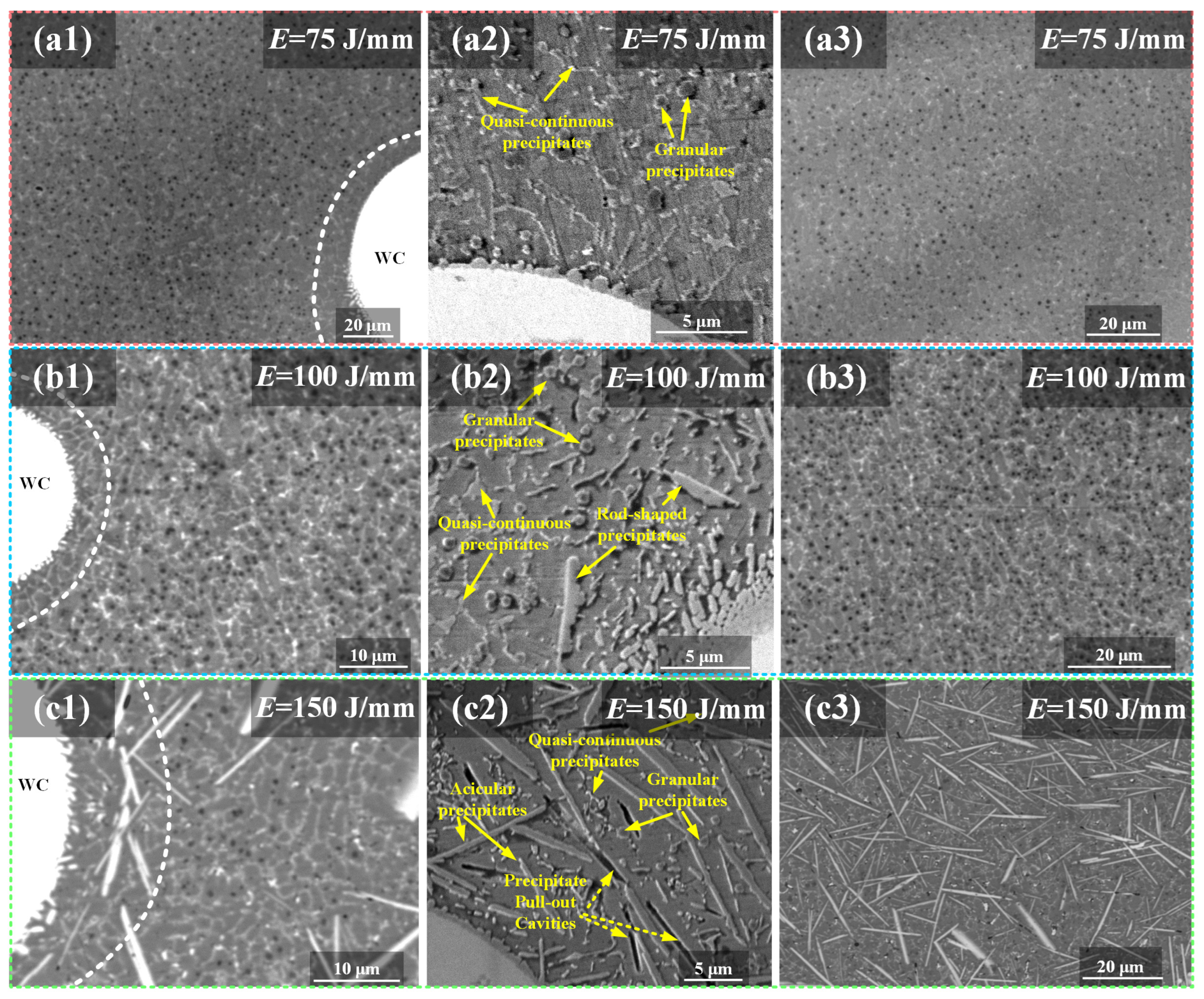
Figure 5 presents backscattered electron (BSE) and secondary electron (SE) images of the CoNiV medium-entropy alloy composite coatings fabricated at different heat inputs. Images (a1–c1) and (a2–c2) show the regions adjacent to residual WC/W2C particles, while images (a3–c3) reveal the matrix far from particles. In BSE mode, contrast arises primarily from differences in atomic number, resulting in dark granular features (corresponding to lower-average-atomic-number precipitates) and bright quasi-continuous phases (higher-average-atomic-number precipitates). In the vicinity of particles (Figure 5(a1–c1,a2–c2)), blocky, rod-shaped, and acicular precipitates preferentially form adjacent to the WC particles. Further into the matrix, homogeneously distributed submicron granular precipitates are observed alongside quasi-continuous phases. At the highest heat input (Figure 5(c2)), precipitate pull-out cavities are clearly visible, indicating weak interfacial bonding between the coarse precipitates and the matrix. In the matrix regions (Figure 5(a3–c3)), the coating prepared at low heat input (Figure 5(a3)) exhibits sparsely distributed submicron granular precipitates and quasi-continuous phases. At medium heat input (Figure 5(b3)), the density of these precipitates increases significantly. However, at high heat input (Figure 5(c3)), the matrix is predominantly occupied by densely distributed coarse acicular and rod-shaped precipitates. These variations in the morphology and distribution of in situ carbide precipitates across the coatings fabricated at different heat inputs are primarily attributed to the varying degrees of WC/W2C particle dissolution in the molten pool.
Figure 5.
BSE and SE images of the regions adjacent to WC/W2C particles and the matrix at different heat inputs: (a1–a3) E = 75 J/mm, (b1–b3) E = 100 J/mm, (c1–c3) E = 150 J/mm.
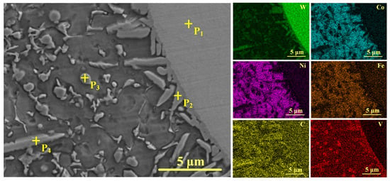
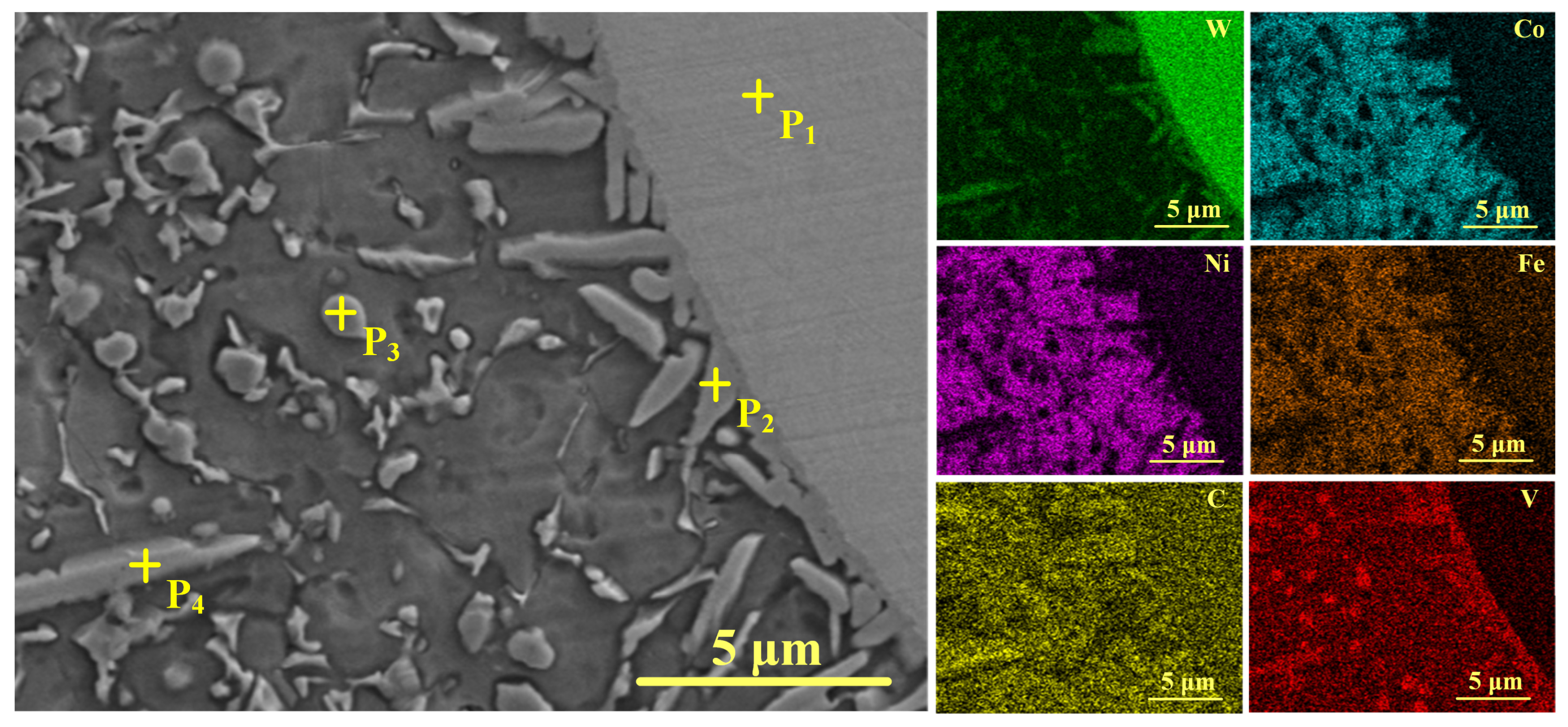
To further determine the composition of the in situ precipitates, EDS and TEM analyses were performed on the coating microstructure. Specifically, Figure 6 presents the secondary electron (SE) image together with the corresponding elemental mapping and point analysis at the dissolution boundary of WC particles and in the surrounding matrix. The quantitative EDS point analysis data are summarized in Table 1. The elemental mapping and point analysis indicate that the precipitates formed at the WC dissolution boundary (P2) are rich in both V and W, confirming the formation of (V,W)-rich carbides. In the matrix, the rod-shaped and acicular precipitates (P4) also exhibit high V and W contents, indicating that they are likewise (V,W)-rich carbides. In contrast, the granular precipitates (P3) are predominantly V-rich carbides. These EDS mapping and point analysis results are in excellent agreement with the VxC and VWC2 phases identified in the XRD patterns.
Figure 6.
EDS mapping and point analysis of the residual WC/W2C particle and the surrounding matrix in the composite coating.
Table 1.
Chemical compositions (at%) of the points (P1–P4) marked in Figure 6.
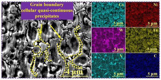
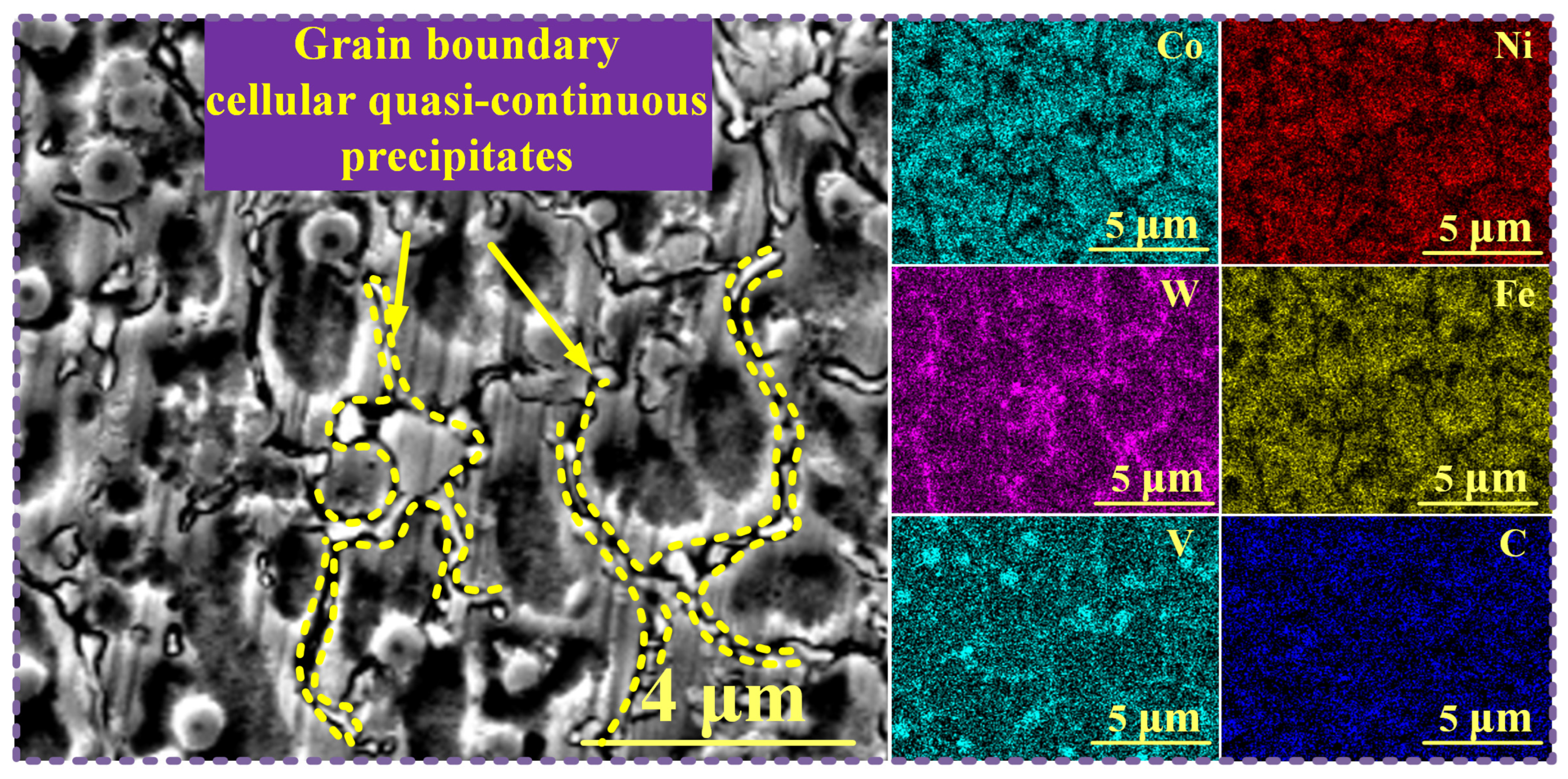
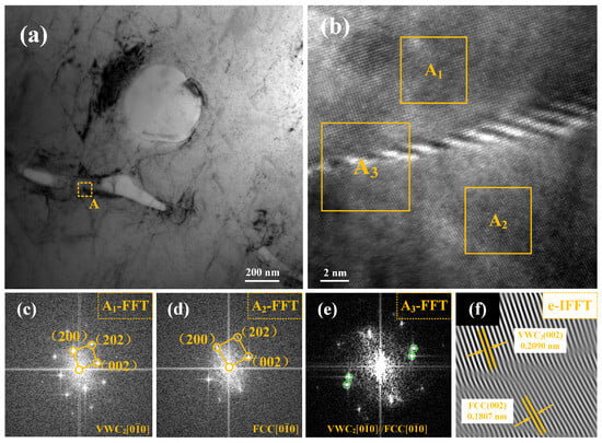
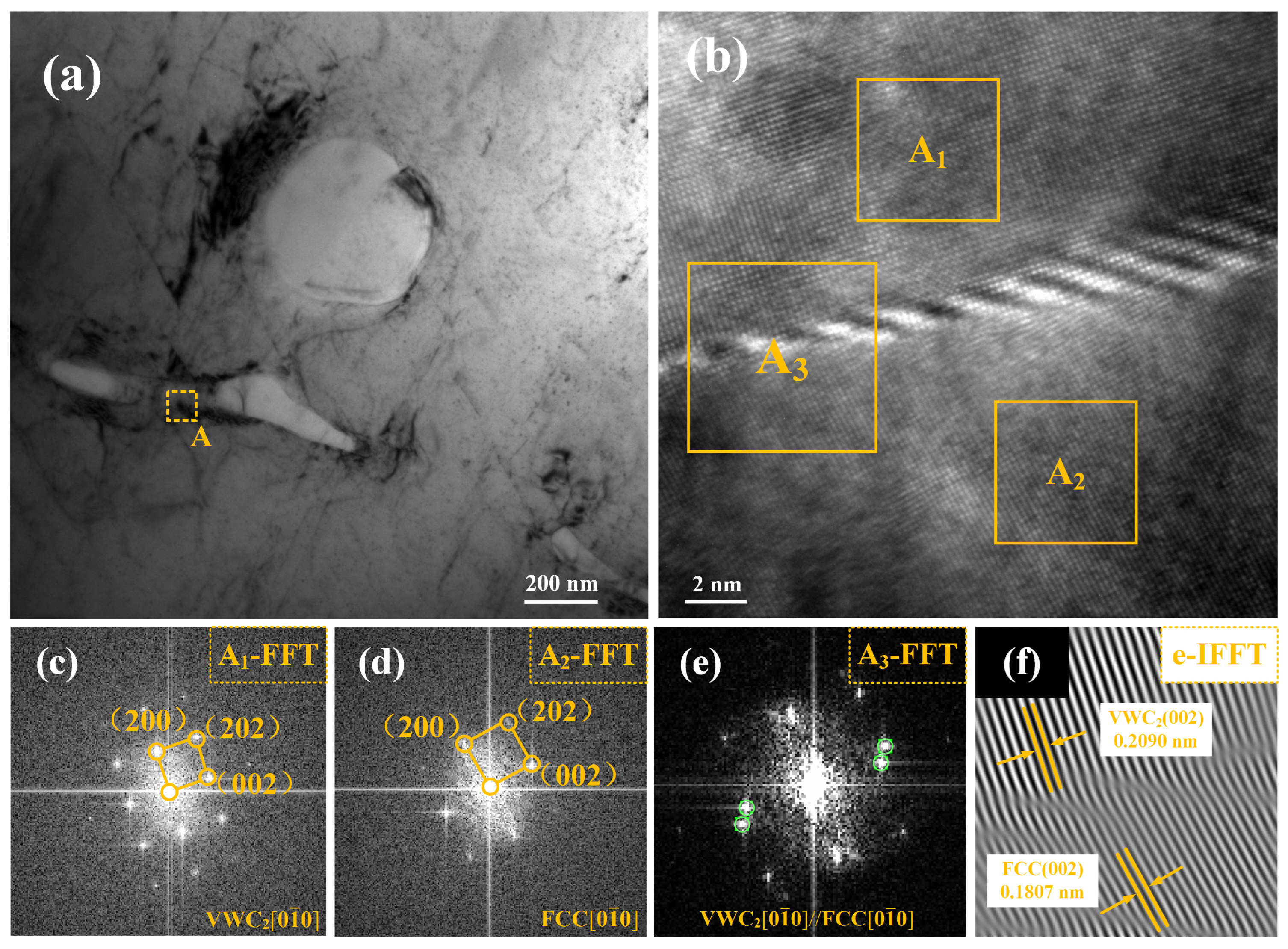
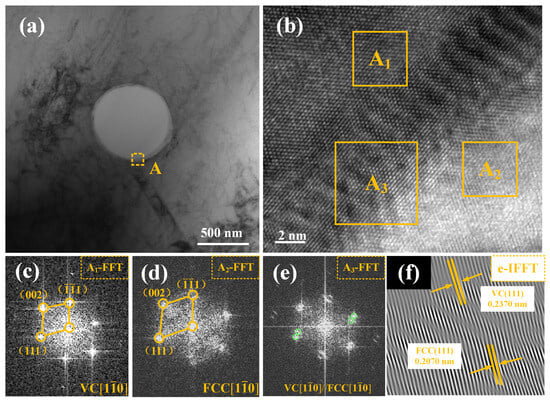
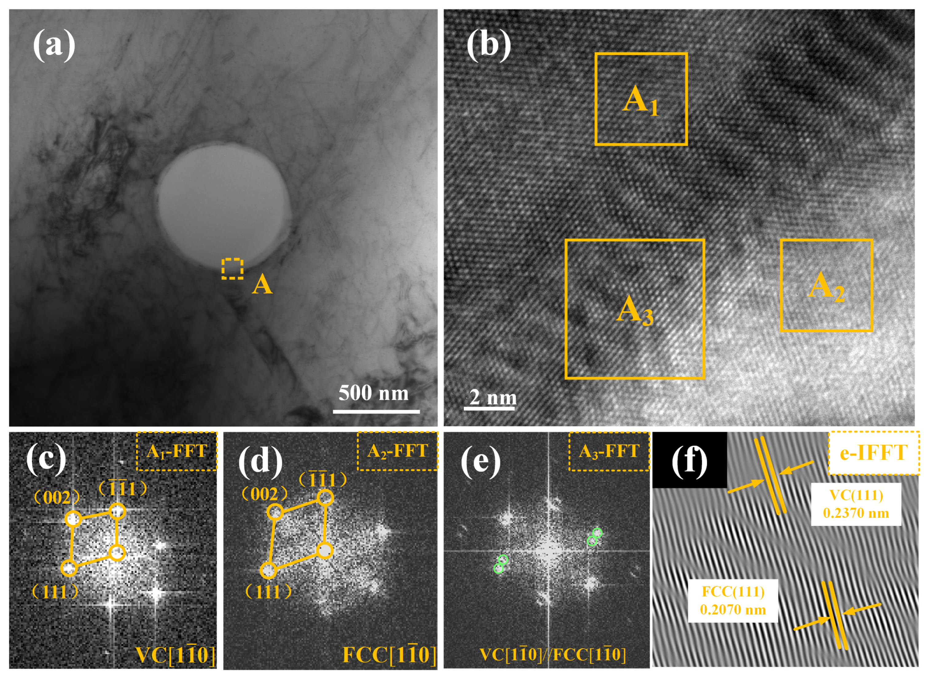
Figure 7 shows the secondary electron (SE) image and the corresponding EDS elemental mapping of the quasi-continuous carbides in the matrix. These quasi-continuous precipitates are distributed along the grain boundaries in a cellular morphology. Elemental mapping further indicates that these precipitates are enriched in V and W. The TEM analysis of the grain-boundary quasi-continuous precipitates is presented in Figure 8. These fine quasi-continuous precipitates are identified as the VWC2 phase. As shown in Figure 8f, the interplanar spacing (d) of the (002) plane was measured to be 0.2090 nm for the VWC2 precipitate and 0.1807 nm for the FCC matrix. The corresponding lattice misfit (δ) between the two phases is calculated to be 13.54%, indicating that the VWC2 precipitates form a semi-coherent interface with the FCC matrix. Similarly, the TEM examination of the granular precipitates (Figure 9) reveals that the selected granular precipitate in this observed region is the VC phase. The interplanar spacing of the (111) plane was determined to be 0.2370 nm for VC and 0.2070 nm for the FCC matrix, yielding a lattice misfit of approximately 12.66%, which also suggests a semi-coherent interface relationship.
Figure 7.
Secondary electron (SE) image and corresponding EDS elemental mapping of the quasi-continuous carbides in the matrix.
Figure 8.
TEM analysis of the grain boundary quasi-continuous precipitates: (a) TEM image; (b) HRTEM image of region A; (c–e) FFT patterns corresponding to areas A1, A2, andA3, respectively; (f) IFFT analysis of the (002) lattice planes.
Figure 9.
TEM analysis of the granular precipitate: (a) TEM image; (b) HRTEM image of region A; (c–e) FFT patterns corresponding to areas A1, A2, and A3, respectively; (f) IFFT analysis of the (111) lattice planes.
The dissolution of WC/W2C particles, elemental diffusion, and subsequent in situ precipitation within the molten pool can be summarized as follows. In the W-rich regions adjacent to WC dissolution boundaries, V from the matrix reacts with dissolved W and C to form blocky, acicular, and rod-shaped precipitates. Simultaneously, driven by the stronger chemical affinity between V and C, the rapid outward diffusion of C triggers the homogeneous nucleation of submicron granular V-rich carbides throughout the matrix. In addition, the interaction between trace W and the V and C atoms leads to the precipitation of quasi-continuous VWC2 at the grain boundaries. At high heat inputs, the extensive dissolution of WC significantly enriches the molten pool with solute atoms, promoting the growth of coarse acicular/rod-shaped phases, while suppressing the formation of fine precipitates. This evolution is consistent with the backscattered electron (BSE) images observed in Figure 5.
3.3. Mechanical and Wear Properties
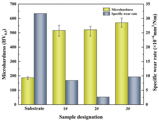
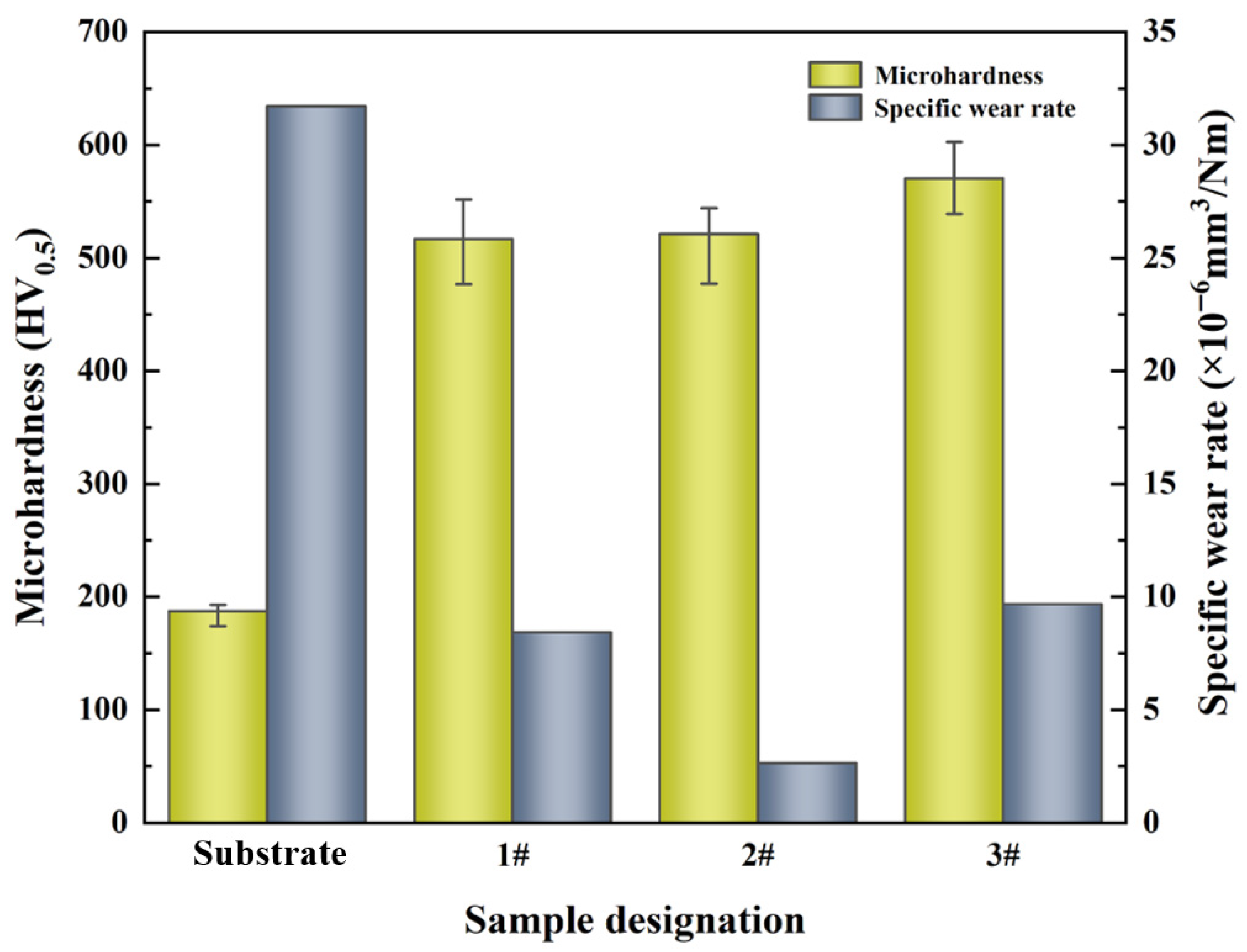
Figure 10 shows the microhardness values of the substrate and the three composite coatings (1#, 2#, and 3#), with heat input increasing from Coating 1# to Coating 3#. The average microhardness values were 187.4 HV0.5 for the substrate, 516.5 HV0.5 for Coating 1#, 521.1 HV0.5 for Coating 2#, and 570.5 HV0.5 for Coating 3#. All three composite coatings exhibit significantly higher microhardness than the substrate, and the hardness increases progressively with increasing heat input. This trend demonstrates that regulating the dissolution degree of WC particles via heat input effectively controls the formation and morphology of in situ carbide precipitates, which in turn influences the hardness of the coatings. Notably, Coating 3# exhibits markedly higher microhardness than Coatings 1# and 2#, which can be primarily attributed to the densely distributed coarse acicular and rod-shaped precipitates formed due to the enhanced WC/W2C dissolution at high heat input.
Figure 10.
Microhardness and specific wear rate of the substrate and the composite coatings.
The specific wear rates of the substrate and the three composite coatings were calculated according to the formula described in Section 2. The measured specific wear rates were 3.171 × 10⁻⁵ mm3·N−1·m−1 for the substrate, 8.439 × 10⁻⁶ mm3·N−1·m−1 for Coating 1#, 2.656 × 10⁻⁶ mm3·N−1·m−1 for Coating 2#, and 9.687 × 10⁻⁶ mm3·N−1·m−1 for Coating 3#. As shown in Figure 10, the wear resistance does not increase monotonically with microhardness. Coating 2# exhibits the lowest specific wear rate (best wear resistance), while Coating 3# shows a higher wear rate despite possessing the highest hardness. This non-linear relationship highlights that the morphology and interfacial bonding strength of the in situ carbide precipitates, which are regulated by the degree of WC dissolution under different heat inputs, play a critical role in determining the overall tribological performance of the coatings.
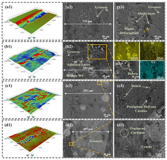
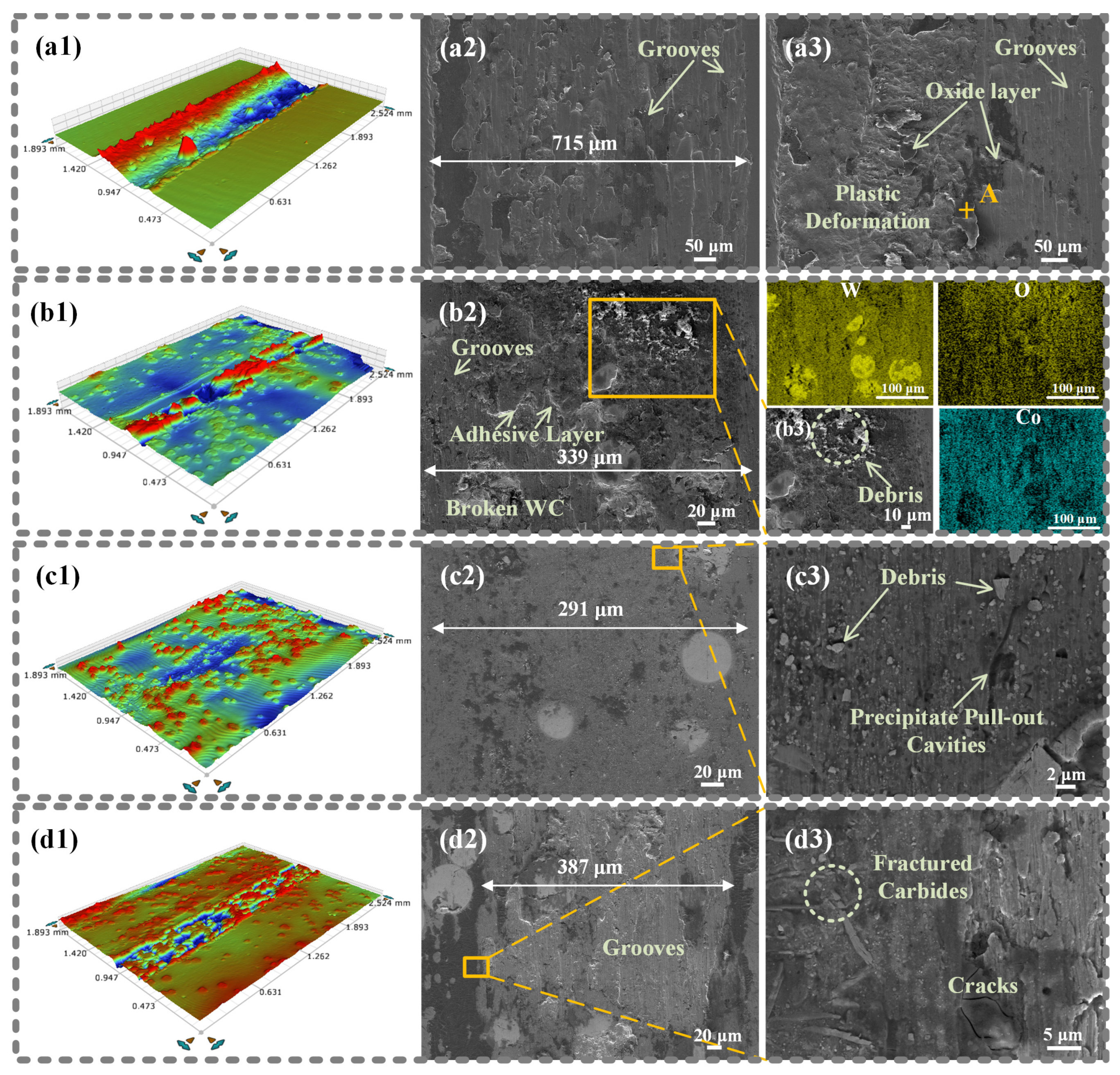
The wear morphology of the substrate (Figure 11(a1–a3)) exhibits pronounced plastic deformation under the action of the harder Si3N4 counterpart, accompanied by flaky delaminated oxide layers indicative of severe adhesive wear [32]. EDS point analysis at point A reveals a composition of Fe35.25-O54.16-Si10.59, signifying oxidative wear debris incorporating delaminated Si3N4 fragments from the counterpart [33]. Therefore, the dominant wear mechanism of the substrate is a combination of oxidative wear, adhesive wear, and abrasive wear.
Figure 11.
(a1–a3) 3D wear track and SEM micrographs of substrate wear morphology, the label “A” in (a3) indicates the location of the EDS point analysis; (b1–b3) 3D wear track and SEM micrographs of the coating fabricated at E = 75 J/mm, where the W/O/Co maps represent the EDS mapping of (b2), and (b3) is the magnified view of the selected area in (b2); (c1–c3) and (d1–d3) are the 3D wear tracks and SEM micrographs of the coatings fabricated at E = 100 J/mm and 150 J/mm, respectively. (b1–b3,c1–c3,d1–d3) 3D wear tracks and SEM micrographs of wear morphologies for the three composite coatings fabricated at different heat inputs.
The coating fabricated at low heat input (75 J/mm, Figure 11(b1–b3)) exhibits severe adhesive delamination and fractured WC particles on the worn surface. EDS elemental mapping confirms the accumulation of oxide debris in the upper-right region of the wear track. Due to the relatively low heat input, the distribution of WC particles is less uniform, resulting in non-uniform wear tracks, as clearly shown in the 3D wear profile (Figure 11(b1)). Moreover, although the microhardness of this coating is close to that of the coating prepared at medium heat input (E = 100 J/mm), the sparse distribution of in situ V-rich granular carbides and grain-boundary quasi-continuous precipitates provides insufficient support to the soft FCC matrix under sliding wear conditions. Consequently, this coating shows a relatively high specific wear rate compared to the medium-heat-input coating.
The coating fabricated at medium heat input (100 J/mm, Figure 11(c1–c3)) exhibits the optimal wear resistance. The worn surface maintains relatively good integrity, with only minor debris, shallow grooves, and trace oxides observed. High-magnification secondary electron imaging (Figure 11(c3)) clearly reveals that the in situ precipitates remain visible beneath the wear track, providing effective structural support to the soft FCC matrix. At this moderate heat input, the controlled dissolution of WC particles promotes the formation of uniformly distributed and densely dispersed fine in situ carbides within the matrix. During sliding, the retained WC particles first bear the compressive and shear stresses from the counterpart, offering a “shadow protection” effect [34], while the fine in situ precipitates reinforce the surrounding FCC matrix. This multi-scale synergistic strengthening between ex situ WC and in situ carbides results in the best overall wear morphology and tribological performance.
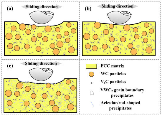
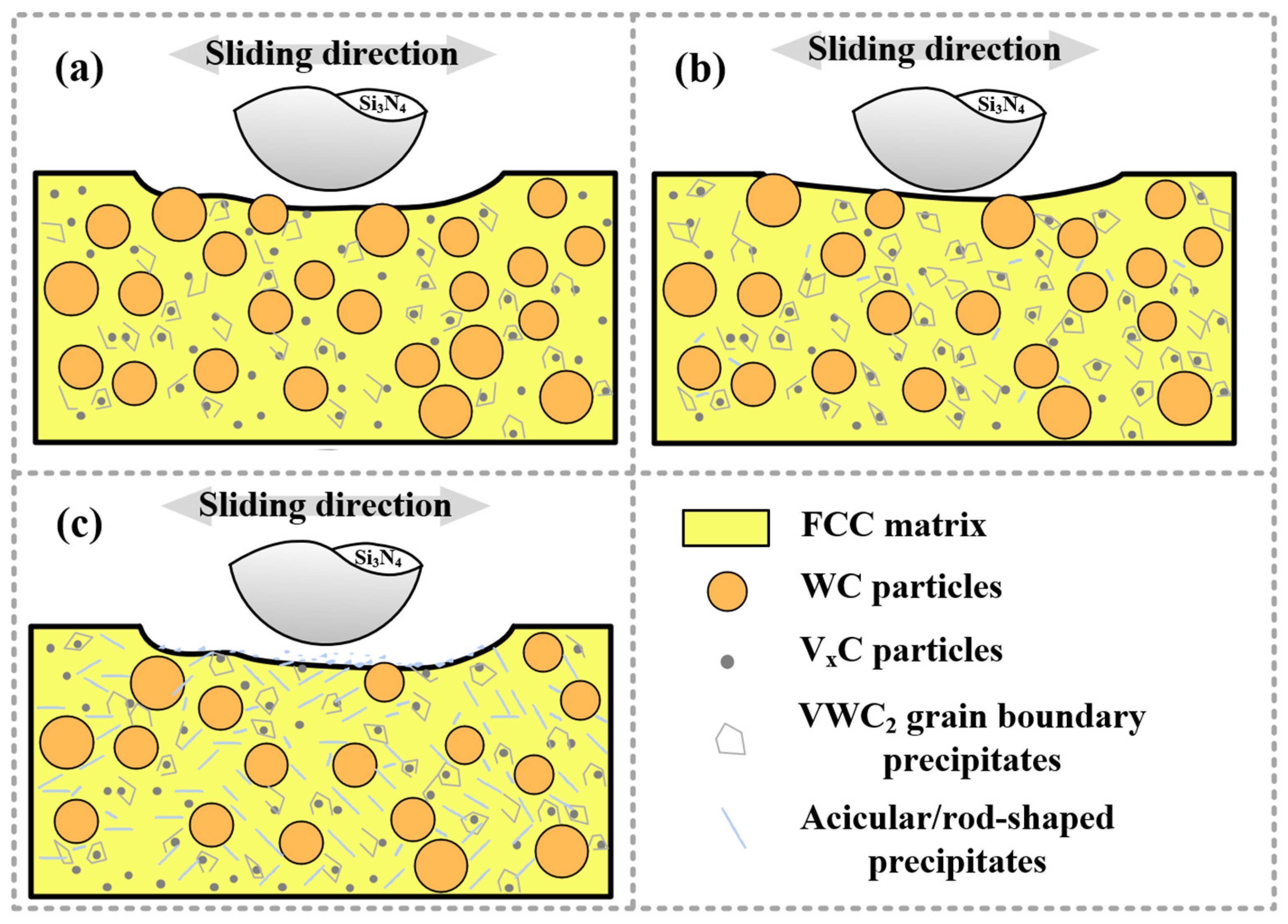
The coating fabricated at high heat input (150 J/mm, Figure 11(d1–d3)) displays distinct oxide layers and extensive abrasive grooves on the worn surface, indicating that abrasive wear and oxidative wear are the dominant mechanisms. Crucially, precipitate pull-out cavities observed in Figure 11(c3) and their fracture morphology at the wear track peripheries (Figure 11(d3)) demonstrate weak interfacial cohesion. At high heat input, severe dissolution of WC/W2C particles leads to the formation of densely distributed coarse acicular and rod-shaped carbides. Due to their sharp edges, angular morphology, and brittle nature, these precipitates are prone to fracture and detachment during sliding. The resulting fragmented debris further exacerbates three-body abrasive wear, significantly deteriorating the tribological environment [35]. This explains the apparent paradox that the coating prepared at the high heat input possesses the highest hardness but exhibits the highest specific wear rate among the three coatings. The wear mechanisms of the three composite coatings are schematically illustrated in Figure 12.
Figure 12.
Schematic illustrations of the wear mechanisms for the three composite coatings: (a) E = 75 J/mm, (b) E = 100 J/mm, and (c) E = 150 J/mm.
4. Conclusions
This study fabricated CoNiV medium-entropy alloy composite coatings reinforced with 40 wt.% WC/W2C particles on carbon steel by laser cladding under different linear heat inputs (75, 100, and 150 J/mm). The influence of heat input on WC dissolution behavior, in situ carbide precipitation, microhardness, and wear resistance was systematically investigated. The main conclusions are as follows:
- The coatings are primarily composed of FCC matrix with retained WC/W2C particles and in situ formed V-rich and VWC2 carbides. The morphology, size, and distribution of these in situ precipitates are strongly dependent on the laser heat input, which controls the dissolution degree of WC/W2C particles.
- The microhardness of the composite coatings increases progressively with the increase in linear heat input, which is attributed to the higher degree of WC dissolution at elevated energy levels, reaching a peak hardness of 570.5 HV0.5 at 150 J/mm. The coarse in situ precipitates formed within these coatings play a significant role in enhancing the microhardness of the matrix.
- The optimal wear resistance is achieved at the intermediate heat input of 100 J/mm, yielding the lowest specific wear rate of 2.656 × 10⁻⁶ mm3·N−1·m−1. This superior performance is attributed to the homogeneous distribution of fine in situ carbides within the matrix, which work synergistically with the retained WC/W2C particles to provide effective multi-scale reinforcement of the FCC matrix. In contrast, the coating deposited at high heat input (150 J/mm) exhibits compromised wear resistance despite possessing the highest hardness, stemming from the fragmentation and detachment of coarse brittle carbides during sliding, which in turn intensifies three-body abrasive wear.
Author Contributions
Conceptualization, Z.Z., M.W. and S.Z.; Methodology, X.B., W.G. and Z.Z.; Software, L.M.; Validation, M.W.; Investigation, J.Y.; Data curation, Y.H.; Writing—original draft, Z.D.; Writing—review & editing, S.Z.; Supervision, L.Y.; Funding acquisition, S.Z. All authors have read and agreed to the published version of the manuscript.
Funding
This research was funded by the National Natural Science Foundation of China (52305399, 52375459), China Postdoctoral Science Foundation (No.2023M742567), and the Tribology Science Fund of the State Key Laboratory of Tribology in Advanced Equipment (SKLTKF25B13).
Institutional Review Board Statement
Not applicable.
Informed Consent Statement
Not applicable.
Data Availability Statement
The original contributions presented in this study are included in the article. Further inquiries can be directed to the corresponding authors.
Conflicts of Interest
The authors declare no conflict of interest.
References
- Abdu, M.T.; Khalifa, W.; Abdelrahman, M.S. Investigation of Erosion-Corrosion Failure of API X52 Carbon Steel Pipeline. Sci. Rep. 2023, 13, 20494. [Google Scholar] [CrossRef] [Scilit]
- Far, A.R.H.; Anijdan, S.H.M.; Abbasi, S.M. The Effect of Increasing Cu and Ni on a Significant Enhancement of Mechanical Properties of High Strength Low Alloy, Low Carbon Steels of HSLA-100 Type. Mater. Sci. Eng. A 2019, 746, 384–393. [Google Scholar] [CrossRef] [Scilit]
- Yu, H.; Wu, K.; Dong, B.; Liu, J.; Liu, Z.; Xiao, D.; Jin, X.; Liu, H.; Tai, M. Effect of Heat-Input on Microstructure and Toughness of CGHAZ in a High-Nb-Content Microalloyed HSLA Steel. Materials 2022, 15, 3588. [Google Scholar] [CrossRef] [Scilit]
- Wang, L.; Wang, S. Study on Austenite Transformation and Growth Evolution of HSLA Steel. Materials 2023, 16, 3578. [Google Scholar] [CrossRef] [Scilit]
- Shi, M.; Li, J.; Shen, C.; Liu, C.; Yang, Z.; Ma, X. Enhancing the Wear and Corrosion Resistance of Q345 Steel via a Martensitic Stainless Steel Hardfacing Coating Deposited by Multiple-Pass MIG Welding. Wear 2026, 584–585, 206365. [Google Scholar] [CrossRef] [Scilit]
- Zhang, Y.; Bai, P.; Li, Z.; Zhang, J. Rapid Optimization of Iron-Based Alloy Laser Cladding Process Based on Orthogonal Experiment and Machine Learning for Q345. Opt. Laser Technol. 2025, 182, 112086. [Google Scholar] [CrossRef] [Scilit]
- Xu, Y.; Zhang, Q.; Ren, W.; Wang, M.; Chen, H.; Zou, X.; Sun, X.; Huang, Y. Interaction of Erosion and Corrosion on High-Strength Steels Used for Marine Dredging Engineering. Wear 2024, 544–545, 205309. [Google Scholar] [CrossRef] [Scilit]
- Rodrigues, T.A.; Duarte, V.R.; Tomás, D.; Avila, J.A.; Escobar, J.D.; Rossinyol, E.; Schell, N.; Santos, T.G.; Oliveira, J.P. In-Situ Strengthening of a High Strength Low Alloy Steel during Wire and Arc Additive Manufacturing (WAAM). Addit. Manuf. 2020, 34, 101200. [Google Scholar] [CrossRef] [Scilit]
- Shen, X.; Liu, C.; Wang, B.; Zhang, Y.; Su, G.; Li, A. Surface Properties of Medium-Entropy Alloy Coatings Prepared through a Combined Process of Laser Cladding and Ultrasonic Burnishing. Materials 2022, 15, 5576. [Google Scholar] [CrossRef] [Scilit] [PubMed]
- Yuan, S.; Wu, S.; Chen, T.; Fu, Q.; Wei, R.; Chen, C.; Wang, T.; Cai, Y.; Li, F. Microstructure and Corrosion Behavior of Co-Free FeCrNiSi0.4 Medium Entropy Alloy Coating Fabricated by Laser Cladding. Intermetallics 2023, 162, 108024. [Google Scholar] [CrossRef] [Scilit]
- Mahaffey, J.; Vackel, A.; Whetten, S.; Melia, M.; Kustas, A.B. Structure Evolution and Corrosion Performance of CoCrFeMnNi High Entropy Alloy Coatings Produced Via Plasma Spray and Cold Spray. J. Therm. Spray Technol. 2022, 31, 1143–1154. [Google Scholar] [CrossRef] [Scilit]
- Vaz, R.; Garfias, A.; Albaladejo, V.; Sanchez, J.; Cano, I. A Review of Advances in Cold Spray Additive Manufacturing. Coatings 2023, 13, 267. [Google Scholar] [CrossRef] [Scilit]
- Wang, W.; Wu, D.; Yin, H.; Zhu, Z.; Gao, Z.; Nie, L.; Liu, Y.; Zou, Y. Research on Additive Manufacturing and Properties of Ni-Al-Cr Medium-Entropy Alloy. Mater. Today Commun. 2025, 46, 112912. [Google Scholar] [CrossRef] [Scilit]
- Wang, W.; Zheng, Y.; Zheng, W.; Shen, Z.; Hu, M.; Wang, Y.; Feng, D.; Ma, Y.; Cai, Z.; Yang, J. Dilution Induced Variation of Microstructure and Mechanical Properties on Co-Cr-Fe-Ni High Entropy Alloy Coatings Prepared by Laser Cladding. Surf. Coat. Technol. 2024, 493, 131256. [Google Scholar] [CrossRef] [Scilit]
- Arif, Z.U.; Khalid, M.Y.; Ur Rehman, E.; Ullah, S.; Atif, M.; Tariq, A. A Review on Laser Cladding of High-Entropy Alloys, Their Recent Trends and Potential Applications. J. Manuf. Process. 2021, 68, 225–273. [Google Scholar] [CrossRef] [Scilit]
- Ouyang, W.; Xu, Z.; Chao, Y.; Liu, Y.; Luo, W.; Jiao, J.; Sheng, L.; Zhang, W. Effect of Electrostatic Field on Microstructure and Mechanical Properties of the 316L Stainless Steel Modified Layer Fabricated by Laser Cladding. Mater. Charact. 2022, 191, 112123. [Google Scholar] [CrossRef] [Scilit]
- Gong, N.; Meng, T.L.; Cao, J.; Wang, Y.; Karyappa, R.; Ivan Tan, C.K.; Suwardi, A.; Zhu, Q.; Ngo, A.C.Y.; Misra, K.P.; et al. Laser-Cladding of High Entropy Alloy Coatings: An Overview. Mater. Technol. 2023, 38, 2151696. [Google Scholar] [CrossRef] [Scilit]
- Tang, J.; Wang, K.; Fu, H. Laser Cladding In Situ Carbide-Reinforced Iron-Based Alloy Coating: A Review. Metals 2024, 14, 1419. [Google Scholar] [CrossRef] [Scilit]
- Zhao, S.; Dong, Z.; Yang, J.; Bao, X.; Gao, W.; Zhao, D.; Wang, M.; Yang, L. Achieving Homogeneous In-Situ Vanadium Carbide Particles Distribution in CoNiV Medium Entropy Alloy Composite Coatings via Laser Cladding. J. Mater. Process. Technol. 2025, 341, 118917. [Google Scholar] [CrossRef] [Scilit]
- Zhang, H.; Liu, G.; Ren, N.; Cheng, N.; Dong, Z.; Ma, Q. Microstructure Evolution and High Temperature Wear Resistance of In-Situ Synthesized Carbides Reinforced NiCoFeCrSiMo High Entropy Alloy Coatings Fabricated by Laser Cladding. Surf. Coat. Technol. 2023, 464, 129573. [Google Scholar] [CrossRef] [Scilit]
- Yu, K.; Cheng, J.; Cheng, Q.; Geng, Y.; Zhu, S.; Liu, M.; Wan, S.; Yang, J. Enhanced Wear Resistance in (CoCrNi)94Al3Ti3 Medium-Entropy Alloy at High Temperatures via Nano-Al2O3 Reinforcing Phase. Tribol. Int. 2024, 195, 109569. [Google Scholar] [CrossRef] [Scilit]
- Liu, X.; Chai, L.; Liu, Y.; Hu, C.; Zhang, C.; Zhong, S. Wear-Resistant CrCoNi-(Ti, Al) Medium-Entropy Alloy Coatings Prepared by Laser Cladding on CrCoNi Medium-Entropy Alloy and Their Microstructural Characteristics. Surf. Coat. Technol. 2024, 477, 130336. [Google Scholar] [CrossRef] [Scilit]
- Nagarjuna, C.; Lee, H.; Dewangan, S.K.; Song, E.; Mohan, M.; Jain, R.; Yu, H.G.; Ahn, B. Strengthening of Fe60Co15Ni15Cr10 Medium Entropy Alloy via Heat-Treatment-Induced Phase Transformation and TiC Reinforcement. J. Alloys Compd. 2025, 1020, 179453. [Google Scholar] [CrossRef] [Scilit]
- Dong, H.; Zhang, Y.; Fen, Y.; Li, P.; Yang, Z.; Han, Y. Optimized High-Temperature Wear Performance of Inconel 625 by in Situ Synthesis of Medium-Entropy Alloy Cladding Layer. Mater. Today Commun. 2025, 42, 111510. [Google Scholar] [CrossRef] [Scilit]
- Okulov, A.; Iusupova, O.; Stepchenkov, A.; Zavalishin, V.; Marchenkova, E.; Liu, K.; Li, J.; Sonar, T.; Makarov, A.; Korobov, Y.; et al. In Situ Ceramic Phase Reinforcement via Short-Pulsed Laser Cladding for Enhanced Tribo-Mechanical Behavior of Metal Matrix Composite FeNiCr-B4C (5 and 7 Wt.%) Coatings. Technologies 2025, 13, 231. [Google Scholar] [CrossRef] [Scilit]
- Zhang, K.; Liu, C.; Wang, W.; Ju, H.; Liu, W.; Wang, H.; Bian, H. Microstructure, Performance, Strengthening and Toughening Mechanisms of WC-Reinforced Inconel 625 Gradient Composite Coating by Laser Cladding on Nonmagnetic Steel. Surf. Coat. Technol. 2025, 496, 131657. [Google Scholar] [CrossRef] [Scilit]
- Shen, X.; He, X.; Gao, L.; Su, G.; Xu, C.; Xu, N. Study on Crack Behavior of Laser Cladding Ceramic-Metal Composite Coating with High Content of WC. Ceram. Int. 2022, 48, 17460–17470. [Google Scholar] [CrossRef] [Scilit]
- Wang, W.; Zhang, K.; Liu, W.; Wu, F.; Chen, S.; Wang, H.; Bian, H. Effect of WC Particle Size on the Microstructure and Properties of FeCoNiCrMn High-Entropy Alloy Composite Coatings by Laser Cladding. J. Therm. Spray Technol. 2025, 34, 1893–1914. [Google Scholar] [CrossRef] [Scilit]
- Guo, C.; Xue, S.; Yue, H.; Dai, W.; Lv, N.; Zhai, J.; Li, Q.; Li, J. Study on the WC Structural Evolution and Wear Behavior of the Cemented Carbide Coatings by Laser Directed Energy Deposition. J. Manuf. Process. 2025, 151, 54–65. [Google Scholar] [CrossRef] [Scilit]
- Wohaibi, S.A.; Mohammed, A.S.; Laoui, T.; Hakeem, A.S.; Adesina, A.Y.; Patel, F. Tribological Characterization of Micron-/Nano-Sized WC-9%Co Cemented Carbides Prepared by Spark Plasma Sintering at Elevated Temperatures. Materials 2019, 12, 920. [Google Scholar] [CrossRef] [Scilit] [PubMed]
- Li, Z.; Xie, D.; Liu, Y.; Lv, F.; Zhou, K.; Jiao, C.; Gao, X.; Wang, D.; Liu, Y.; Zu, H.; et al. Effect of WC on the Microstructure and Mechanical Properties of Laser-Clad AlCoCrFeNi2.1 Eutectic High-Entropy Alloy Composite Coatings. J. Alloys Compd. 2024, 976, 173219. [Google Scholar] [CrossRef] [Scilit]
- Wu, H.; Wang, L.; Zhang, S.; Wu, C.L.; Zhang, C.H.; Sun, X.Y.; Chen, J. Tribological Properties and Sulfuric Acid Corrosion Resistance of Laser Clad CoCrFeNi High Entropy Alloy Coatings with Different Types of TiC Reinforcement. Tribol. Int. 2023, 188, 108870. [Google Scholar] [CrossRef] [Scilit]
- Chen, L.; Lan, Y.; Cheng, Y.; Zeng, J.; Ma, Y.; Yu, S.; Ding, Z.; Liu, B.; Zhang, J.; Peng, H.; et al. Friction Behavior and Wear Mechanism of Laser Cladded FeNiCr-WC Composite Coatings in Comparison with Different Friction Pairs. J. Mater. Res. Technol. 2024, 31, 1956–1973. [Google Scholar] [CrossRef] [Scilit]
- Detao, L.; Chuang, H.; Fan, W.; Dejun, K. Effect of B4C Addition on Microstructure and Tribological Performance of Laser Cladded WC−10Co4Cr Coatings. J. Mater. Sci. 2023, 58, 5822–5836. [Google Scholar] [CrossRef] [Scilit]
- Tiwari, V.; Mandal, V.; Sarkar, M.; Kumar, A.; Bhagyaraj, J.; Singh, M.K.; Mukherjee, S.; Mondal, K.; Ramkumar, J.; Jain, J.; et al. Enhanced Mechanical Properties and Microstructure of TiC Reinforced Stellite 6 Metal Matrix Composites (MMCs) via Laser Cladding Additive Manufacturing. J. Alloys Compd. 2025, 1010, 178001. [Google Scholar] [CrossRef] [Scilit]

Disclaimer/Publisher’s Note: The statements, opinions and data contained in all publications are solely those of the individual author(s) and contributor(s) and not of MDPI and/or the editor(s). MDPI and/or the editor(s) disclaim responsibility for any injury to people or property resulting from any ideas, methods, instructions or products referred to in the content. |
© 2026 by the authors. Licensee MDPI, Basel, Switzerland. This article is an open access article distributed under the terms and conditions of the Creative Commons Attribution (CC BY) license.