


Abstract
Radiant porous burners are favored in household and industrial applications for their high flexibility, minimal emissions, and excellent fuel adaptability. Enhancing heating temperature uniformity improves the heat transfer efficiency and heating quality. This work presents a two-dimensional numerical study on the non-uniformity of the heating temperature (i.e., solid temperature at the burner exit) in a cylindrical porous burner. The root mean square (RMS) of the heating temperature () is used to quantify the non-uniformity. From the numerical results, the cylindrical porous burner exhibits a non-uniform heating temperature and a non-uniform mass flow rate of flue gas at the sub-outlets. The surface emissivity and equivalence ratio have minor effects on the . However, increasing the volumetric flow rate and solid temperature leads to a more uniform distribution of heating temperature. The decreases from 40 K to 4.4 K as the volumetric flow rate increases from 26.75 slm (standard liters per minute) to 87 slm at an equivalence ratio of 0.96 and emissivity of 0.85. Meanwhile, the results demonstrate that increasing the thermal conductivity of the porous shell improves the heating temperature uniformity. This study presents guidelines for enhancing the uniformity of heating temperature for the cylindrical porous burner.
1. Introduction
Radiant porous burners have been widely used in households and industry due to their uniform and efficient heating [1], wide dynamic range [2], small pollutant emissions [3], and good interchangeability of fuels [4]. The indicators for the evaluation of radiant porous burners are comprehensive: radiative efficiency, uniformity of heating temperature, fuel interchangeability, stability limit, pollutant emissions, etc. [5].
In previous studies, researchers have focused on improving radiative efficiency [6]. There has been little attention paid to the non-uniformity of heating temperature, although this indicator has a significant influence on the characteristics of radiative heat transfer and heating quality.
It has been established in the literature that optimizing the structure of porous media, altering burner geometry, and increasing oxygen concentration are effective strategies for enhancing radiative efficiency. Structural optimization of porous media applied in the burner with the intention of improving radiative efficiency was conducted by Weinbrecht et al., who found that the radiative efficiency was heavily dependent on the specific area of porous media [7]. The highest radiative efficiency of 0.3 was achieved by the burner with the largest specific area of a foam structure.
Wieland et al. performed a pore-level three-dimensional numerical study on a two-layer burner made of regular porous media [8]. A skeletal chemical kinetic mechanism was applied to model premixed methane/air combustion within the pores. It was found that the radiative efficiency depended heavily on the specific surface area. Yakovlev et al. studied experimentally and numerically the flame stabilization in a two-layer porous burner with metallic porous media [9]. They conducted pore-resolved numerical simulation of the porous burner with the symmetric geometric figuration to save computational burden. It was found that the flame stabilization mechanism at lower flow velocity was similar to that of bluff bodies.
Both the exhaust gas temperature and heating temperature of a plane two-layer burner with dimensions of 185 mm × 135 mm were measured by Keramiotis et al. [10]. The exhaust temperatures were measured at a 1 mm height above the burner surface; homogeneous gas temperatures above the burner surface beside the wall were verified. The heating temperatures were measured using an infrared thermal imager. Even temperature distributions over different thermal loads were confirmed qualitatively; however, the non-uniformity of heating temperature was not quantitatively studied in their study.
Cylindrical porous burners [11,12,13,14] have significant advantages in improving radiative efficiency compared with the conventional planar porous burners [7,8]. A general radiative efficiency of 20%–30% was reported for the conventional one [7,8]. However, the greater radiative efficiency of cylindrical porous burners has been validated experimentally and numerically by many researchers. Vahidhosseini et al. developed and tested a cylindrical porous burner [11]. The flame was confined within the hollow of the Ni-Al or porous shell with a smaller pore diameter; the porous burner was covered by a coaxial cylindrical quartz. The radiative efficiencies of 0.41–0.55 were predicted by the numerical simulation. Again, the non-uniformity of heating temperature was not reported.
In the literature, Fursenko et al. proposed a cylindrical porous burner composed of a hollow space and porous Ni-Al-alloys [12]. It was demonstrated that there were two flame stabilization mechanisms, namely combustion within the hollow space surrounded by the porous Ni-Al-alloys and flame stabilization at the outer surface of the porous shell for the same operating parameters, depending on the initial ignition position. They found that the radiative efficiency under internal combustion was always higher than that of external combustion for the same operating parameters. The maximum radiative efficiency under internal combustion reaches 0.62 for a firing rate of 150 . However, the non-uniformity of the heating temperature was not reported in this reference. Subsequently, Maznoy et al. studied experimentally the influence of the porous structure of Ni-Al on the radiative characteristics [13]. The experimental results indicated that the smaller pore size of intermetallic Ni-Al was recommended to gain greater radiative efficiency.
Lee and Noh studied experimentally and theoretically the excess enthalpy flames stabilized in a radial multi-channel as a model cylindrical porous medium burner [14]. Vahidhosseini et al. studied the energy saving of a cylindrical porous burner applying the response surface method by ANSYS Fluent 19.0 [15]. The effect of equivalence ratio and input power on the radiative efficiency was investigated; the parameters for energy saving and radiative efficiency improvement were presented. Abdulkarim et al. modeled a cylindrical two-staged burner based on a 3D solid computer model using Star CCM [16]. Porous media with greater and smaller pores were recommended to be applied at the upstream and downstream sections of the burner to obtain an even distribution flow at the outlet. The experimental study by Abdelaal et al. showed that the radiative efficiency could be improved by 22% by applying 23% oxygen concentration in the fuel/air mixture. Catapan et al. studied experimentally the effect of non-uniform inlet velocity on the flame stabilization within a two-layer porous burner [17]. It was found that the regime of the flame stabilization was dependent on the inlet velocity. The shape of the flame front was conical at the lower inlet velocity and then became a flat flame located at the external burner surface as the inlet velocity was increased.
While the radiative efficiency of cylindrical porous burners has been extensively studied and improved through structural and combustion mode optimization, a critical performance indicator—the uniformity of the heating temperature () at the burner outlet—has received scant attention. As highlighted in the literature [10,12], although an even temperature distribution is qualitatively desired for high heating quality and efficient radiative transfer, a systematic, quantitative investigation into its non-uniformity remains lacking.
Previous studies have primarily focused on maximizing radiative output, often reporting only average temperatures without a metric to quantify spatial variations. The limited number of experimental temperature measurements is inadequate to fully capture the uniformity of the heating temperature at the burner outlet.The root causes and extent of heating temperature non-uniformity, along with strategies to mitigate it, remain insufficiently explored. This constitutes a significant gap in the literature, as non-uniform heating can lead to inconsistent product quality and suboptimal heat transfer efficiency in industrial applications. The present study aims to bridge this gap. The numerical study fills a critical research gap by providing the first quantitative, mechanistic analysis of heating temperature non-uniformity, offering a reproducible framework for optimizing cylindrical porous burner performance. Unlike previous works, we employ the Root Mean Square (RMS) of the solid temperature at the burner exit () as a definitive metric to quantify non-uniformity. Furthermore, we elucidate the combined effects of key operational parameters (volumetric flow rate, equivalence ratio) and material properties (surface emissivity, thermal conductivity) on this uniformity. This approach provides novel insights that move beyond average performance metrics, offering practical guidelines for designing burners with superior heating homogeneity.
Based on the identified research gap, the main objectives of this work are explicitly defined as follows:
- (1)
- To develop a robust numerical model for a cylindrical porous burner and validate its capability to capture temperature distribution trends.
- (2)
- To quantitatively evaluate the non-uniformity of the heating temperature () using the RMS metric () and analyze the underlying flow and heat transfer characteristics that cause it.
- (3)
- To systematically investigate the individual and comparative influences of the volumetric flow rate, equivalence ratio, surface emissivity, and thermal conductivity of the porous shell on the degree of heating temperature uniformity.
- (4)
- To present clear guidelines for enhancing heating temperature uniformity, thereby improving the overall performance and application potential of cylindrical porous burners.
This study provides a foundational understanding and quantitative framework for optimizing heating uniformity, an aspect crucial for advancing high-quality industrial heating processes.
2. Physical and Mathematical Models
2.1. Physical Model
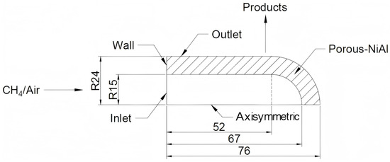
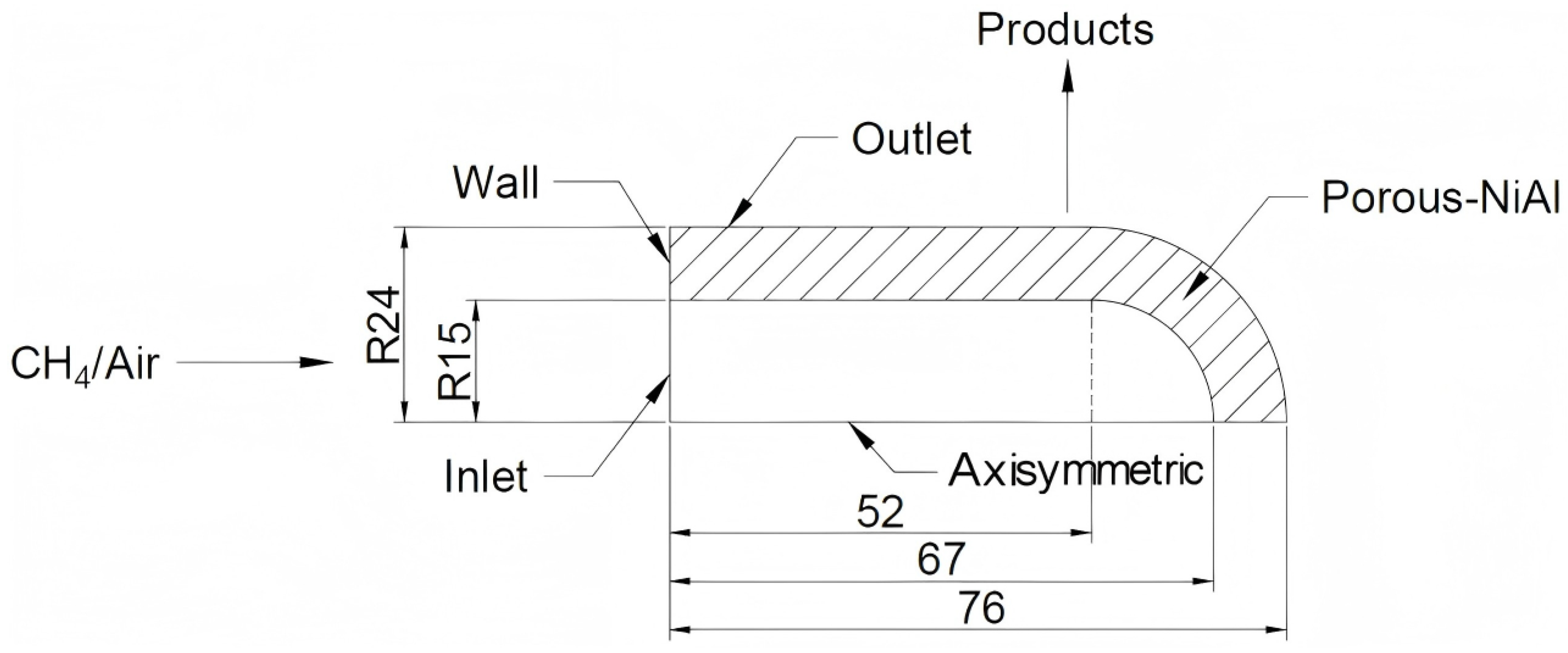
The modeled porous burner [12] is an axisymmetric cylindrical shape with a hemispheric head, whose computational domain is shown in Figure 1. It is composed of a hollow space followed by porous Ni-Al with different thicknesses, as shown in Figure 1. The porous Ni-Al with a thickness of 9 mm is adopted for the present simulation. The previous study [12] showed that the thickness of porous shell had a minor effect on the radiative efficiency. The external diameter of the cylindrical porous burner is 48 mm with a length of 76 mm. The porosity of the porous Ni-Al and its pellet size are specified as 0.625 mm and 0.55 mm [12], respectively.
Figure 1.
Schematic view of the cylindrical porous burner (all dimensions are in millimeters).
2.2. Mathematical Model
In the previous article, little information regarding the flame stabilization of premixed methane/air combustion in the hollow space was provided, so it was very difficult to achieve stable combustion of the premixed mixture in the open space without a stable method like bluff body. Meanwhile, the focus of this work is to study the non-uniformity of heating temperature; thus, the combustion in the hollow space is ignored in the present simulation. Instead, the combustion products, CO2, O2, H2O, and N2, with a theoretical combustion temperature, are assumed to enter the burner through the inlet. The flow and heat transfer in the burner are simulated based on the Volume Averaged Method (VAM).
To simplify the calculation, the assumptions are as follows,
- (1)
- The combustion within the hollow space is ignored; the mixture entering the burner is assumed to be the combustion products with a theoretical combustion temperature and mixture compositions;
- (2)
- The mixture radiation is considered based on the Discrete Ordinates model;
- (3)
- The porous Ni-Al is an optically thick medium, whose radiation is computed by the Rosseland model. Under the above assumptions, the governing equations are obtained based on VAM [4].
The pressure loss of the gas mixture passing through the porous Ni-Al is calculated according to the following formula [18].
where d represents the pellet diameter of porous Ni-Al.
where denotes the thermal conductivity of porous Ni-Al, and represents solid radiation under diffusion approximation [12,13],
where is the extinction coefficient of porous Ni-Al, and is the Stefan–Boltzmann constant.
The convective heat transfer coefficient between gas and solid phases, , is computed as [19]:
where L is the thickness of the porous shell. It should be noted that Equation (7) is always applied for reticulated alumina foam [19]. It is applied here because of the lack of availability of a correlation for porous Ni-Al.
2.3. Boundary Conditions
At the burner inlet,
Along the burner axis,
A no-slip boundary condition is assigned at the wall.
The thermal radiation through the external porous surface is calculated by:
where is the emissivity of the Ni-Al surface, is the exit solid temperature (heating temperature), and is the Stefan–Boltzmann constant. The radiative efficiency, , is defined as the radiative output to the total thermal input.
Gas properties are specified as a function of gas composition and temperature. The physical properties of the porous Ni-Al alloy are taken from References [9,11,20].
2.4. Grid Generation, Initial Conditions, and Solution Strategies
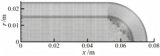
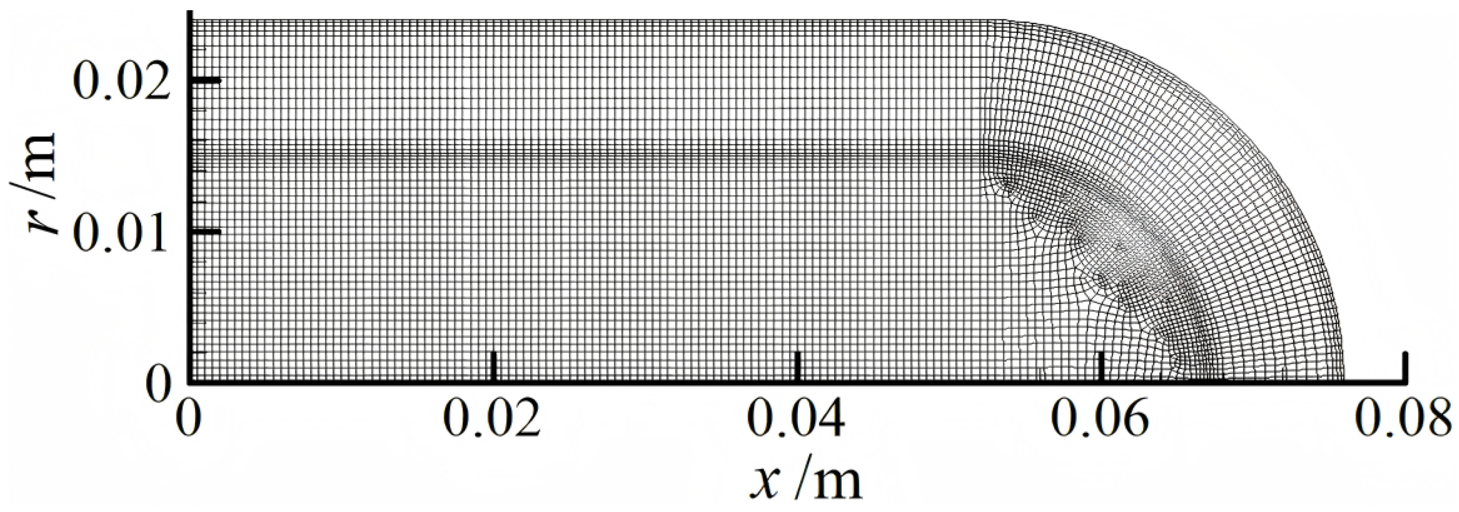
The calculation area is divided into 7770 square cells with different sizes. Fine meshes are applied near the interfaces between the fluid and porous zones, as shown in Figure 2. The minimum and maximum cell sizes in the computational zone are 0.2 mm and 0.5 mm, respectively. The sensitivity analysis of the grid has been conducted, which indicates that further increasing the present number of grids has a minor impact on the calculation results. The initial values of variables are specified as the values at the burner inlet; the temperature within the porous shell is set as an ambient temperature of 300 K.
Figure 2.
The meshes applied in the computational domain.
The solution of the established governing equations with boundary condition is found by applying software Fluent 15.0 [18]. The partitioned mesh file is imported into Fluent 15.0, and the “Porous shell” zone is selected and activated as the “porous media”, while the remaining zones are set as fluid regions by default. Within the activated porous media zone, it is possible to input parameters such as the porosity and physical properties of the porous material, as well as relevant parameters for calculating the pressure loss as the fluid passes through the porous medium. These correspond to defining the diffusion coefficient and source term for the solid energy equation, as well as the additional pressure loss term in the momentum equation. After selecting the fluid as an incompressible ideal gas, Equation (10) is effectively activated. The system of Equations (1)–(10), along with the boundary conditions (11)–(13), can then be solved by Fluent 15.0. A pressure-based solver is employed with the SIMPLE algorithm for pressure–velocity coupling, and second-order upwind discretization schemes are applied for the momentum and energy equations. The diffusion and source terms in the solid energy equation are established using User Defined Functions (UDFs). The convergence criteria are set as residuals below for the energy equation and for all other equations.
The root mean square (RMS) of the heating temperature, denoted as , is used as the quantitative indicator to evaluate the degree of non-uniformity, which is defined as [21],
where is the average temperature of the heating temperature, and is the local solid temperature along the burner outlet. The unit of is Kelvin (K). A lower value indicates a more uniform temperature distribution at the outlet. The metric is selected because it directly reflects the spatial variation of the heating temperature, which critically influences heat transfer efficiency and heating quality in applications such as material processing or steam generation. A highly non-uniform temperature profile can lead to localized overheating or underheating, reducing process consistency and product quality. Thus, minimizing is essential for improving burner performance in practical systems.
3. Results and Discussion
3.1. Comparison with Available Experimental Data
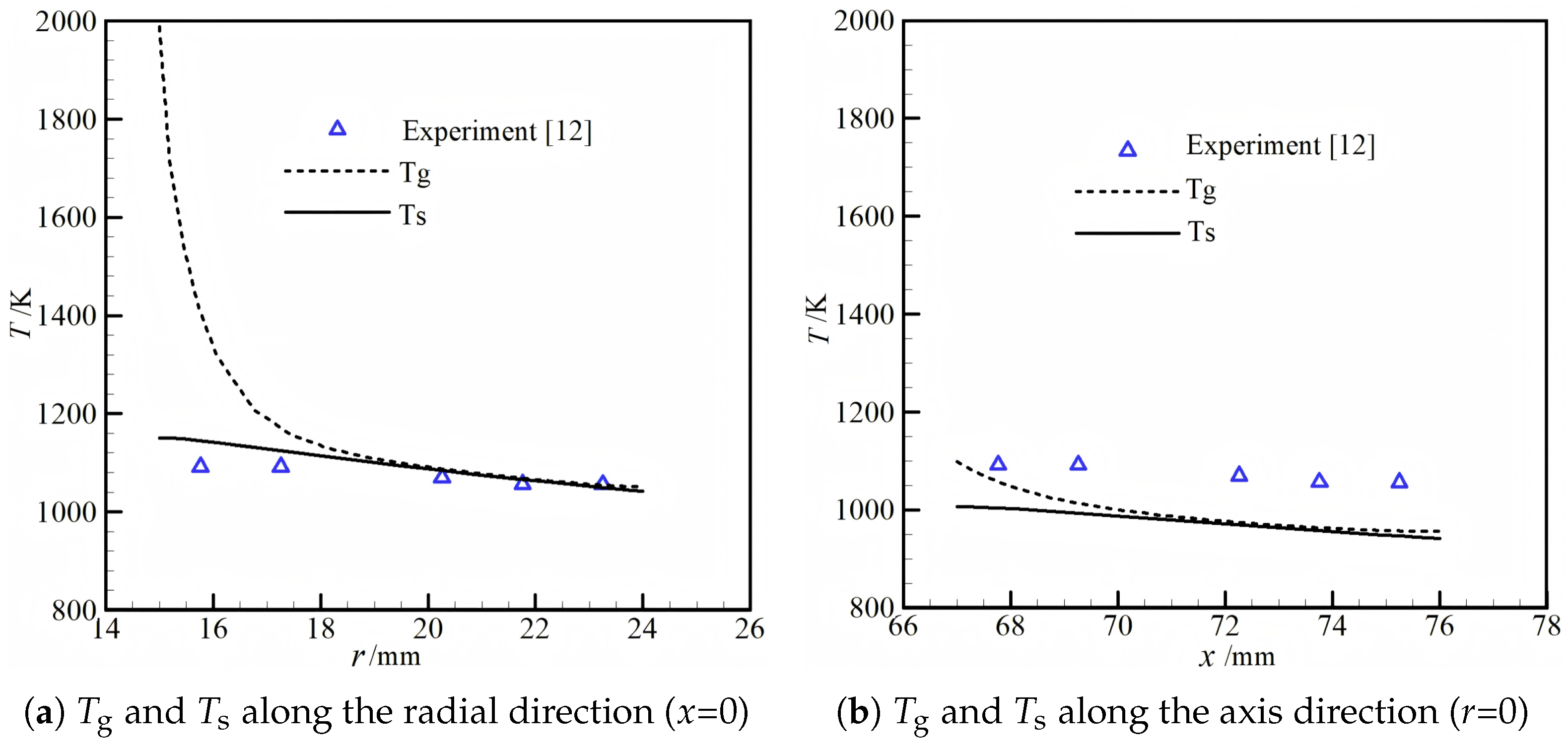
Figure 3 plots the comparisons between the predicted gas and solid temperatures for a volumetric flow rate of 26 slm, equivalence ratio () of 0.96, and surface emissivity () of 0.85. Experimental results [12] are also presented for the purpose of comparisons. Notably, the temperature distributions along the radial direction in the porous shell were measured by multiple thermocouples, but the positions of the x-coordinate for the inserted thermocouples were not presented [12].
Figure 3.
The comparisons between the predicted gas, solid temperature, and experiments [12] for a volumetric flow rate of 26 slm, and .
The measured temperatures decrease linearly along the radial direction due to the radiation output to the ambient, as shown in Figure 3a. Figure 3a,b present the predicted gas and solid temperatures along the radial direction (x = 0) and axis direction (r = 0), respectively. The predicted solid temperatures along the radial direction are greater than the experiments, while the predictions along the axis direction are smaller than the experimental values. Firstly, our predictions show that the solid temperature decreases along the axis direction for all computed cases. This indicates a non-uniform temperature distribution in this type of burner, which will be further investigated in the following section. Secondly, a linear decrease trend of solid temperature along the radial direction is predicted by our model, which is consistent with the variation trend of experimental results. Furthermore, the effect of the properties of porous Ni-Al on the distribution of the porous shell needs further study; we will also investigate this effect in the following section. However, detailed comparisons between the predictions and experiments are impossible because of the unknown x-coordinate of thermocouples in the experiment, and the validation is qualitative only. A level of model accuracy cannot be fully supported by such a comparison.
3.2. The Non-Uniformity of Heating Temperatures
3.2.1. The General Characteristics of Cylindrical Porous Burner
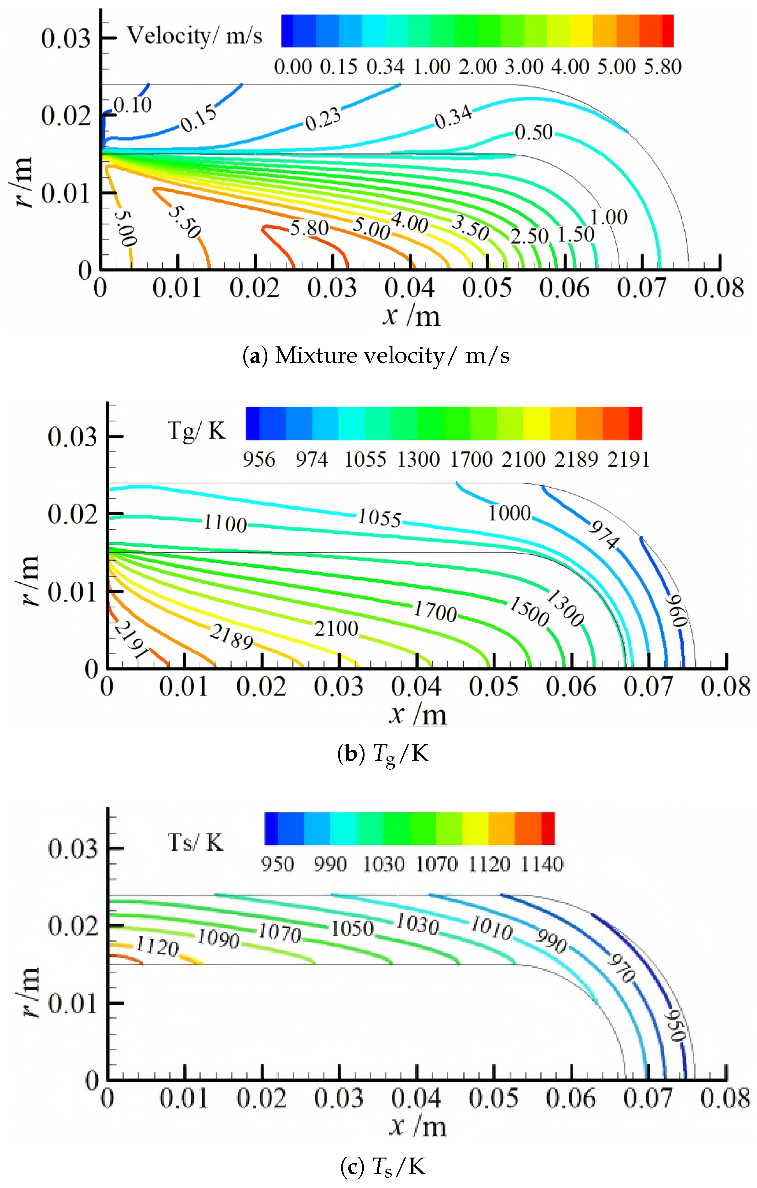
Figure 4 presents the mixture velocity (a), gas-phase temperature (b), and solid-phase temperature (c) distributions within the cylindrical porous burner for a volumetric flow rate of 26 slm, and .
Figure 4.
The distributions of mixture velocity, gas, and solid temperatures in the cylindrical porous burner for a volumetric flow rate of 26 slm, and .
When high-temperature flue gas enters the inner hollow of the burner, the majority of the gas flows along the axial direction due to the mixture inertia, as shown in Figure 4a. At the same time, the mixture continually flows in the porous shell and a part of it leaves the burner through the burner outlet, so the mixture velocity in the hollow of the burner decreases gradually with x-axial, while the velocity in the porous shell gradually increases with x-axial, as shown in Figure 4a. It should be noted that the velocity within the hollow of the burner is generally greater than the velocity in the porous shell because of the enlarged flow area; the area ratio of the burner outlet to the inlet is 16.2. The mixture temperature at the burner inlet is specified as a theoretical combustion temperature of 2191 K for = 0.96, as shown in Figure 4b. As the flue gas enters the burner hollow, the main stream of the mixtures flows along the x-axis and heat exchange takes place between the gas and solid skeleton; thus, the gas temperature in the hollow space decreases gradually along the x-axis, and the mixture’s temperature decreases from 2191 K at the burner inlet to about 1300 K around the end of the porous shell. As the mixture enters the porous shell, the gas temperature decreases sharply because of the convective heat transfer between the gas and solid, as shown in Figure 4b.
The solid temperature varies within the range of 950–1140 K, as shown in Figure 4c. It can be seen that the solid temperature decreases both in the axial and radial directions. Firstly, the solid temperature decreases in the radial direction due to the radiative output through the burner outlet. Secondly, the decrease in the solid temperature in the axis direction is because the gas temperature decreases along the axis direction. As shown in Figure 4b, the gas temperature decreases gradually in the axis direction; meanwhile, part of it continually enters the porous shell and convective heat transfer occurs between the gas and solid phase. Thus, the solid temperature decreases continually along the axis direction.
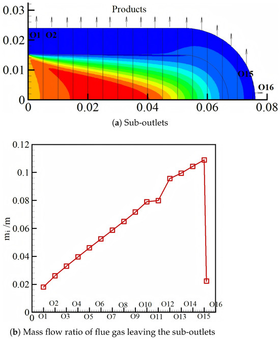
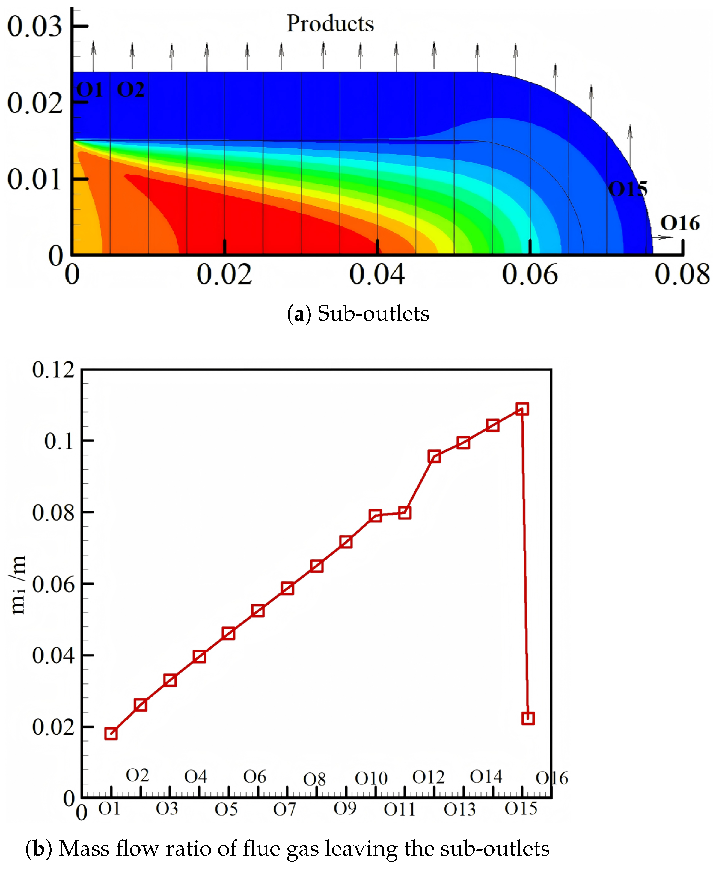
To further investigate the general characteristics of this type of burner, the mass flow ratio of flue gas leaving the burner outlet at different positions is computed across the burner outlet, as shown in Figure 5.
Figure 5.
The sub-outlets and distributions of mass flow ratio at different sub-outlets for a volumetric flow rate of 26 slm, and .
It is assumed that the burner outlet is divided into multiple sub-outlets with = 5 mm along the axis direction, and the obtained sub-outlets are marked with O1, O2, and so on, as shown in Figure 5a. The mass flow ratio () is defined as the mass flow flowing out through a single sub-outlet divided by the total input mass flow. As shown in Figure 5b, the mass flow ratio increases linearly along the flow direction (or the number of sub-outlet) except for the last sub-outlet. This may be due to the mixture inertia. The majority of the mixture flows along the x-axis.
Based on the above results and discussion, it can be concluded that the cylindrical porous burner is characterized by non-uniform heating temperatures and non-uniform mass flow rates of the flue gas leaving its sub-outlets, under the assumption of flue gas with a theoretical combustion temperature and its mixture compositions entering the burner. In the following section, we will investigate the extent of the non-uniformity of heating temperature under the different operating conditions and thermal properties of porous Ni-Al.
3.2.2. Effect of Volumetric Flow Rate on the Heating Temperature and Its RMS
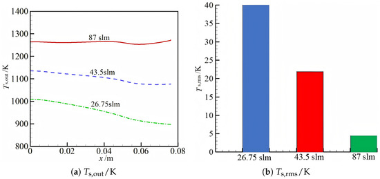
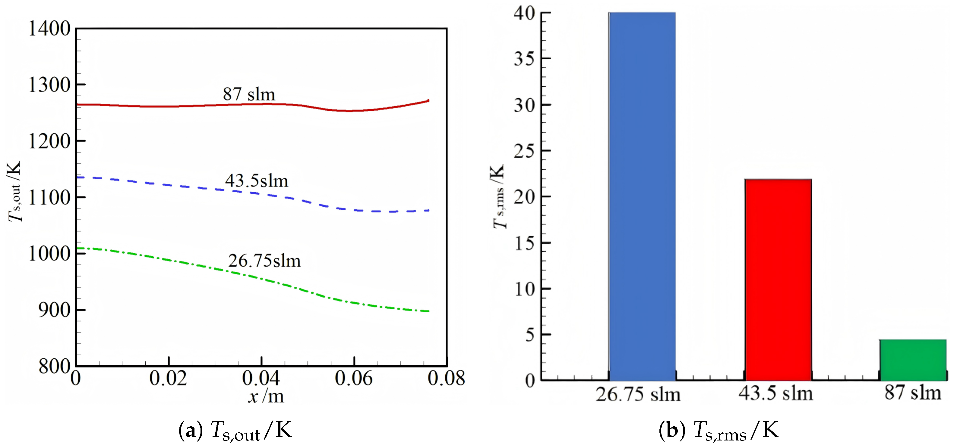
Figure 6 plots the effect of the volumetric flow rate on the heating temperature and its RMS for = 0.96 and = 0.85. The greater the mass flow rate, the higher heating temperature of the burner is achieved, as expected. Meanwhile, the decrease rate of the heating temperature with the x-axis becomes larger as the volumetric flow rate is decreased from 87 slm to 26.75 slm with the fixed equivalence ratio and emissivity, as shown in Figure 6a. For example, the reduction amplitudes of the heating temperature from x = 0 m to x = 0.076 m for 43.5 slm and 26.75 slm are 59 K and 112 K, respectively.
Figure 6.
The effect of volumetric flow rate on the heating temperature and its root mean square for , .
As shown in Figure 6b, a significant drop in the with volumetric flow rate is observed. The decreases from 40 K to 4.4 K with an increase in the volumetric flow rate from 26.75 slm to 87 slm. In all, the is strongly influenced by the volumetric flow rate; a more uniform distribution of the heating temperature can be achieved at a greater volumetric flow rate with the constant equivalence ratio and emissivity.
3.2.3. Effect of Equivalence Ratio on the Heating Temperature and Its RMS
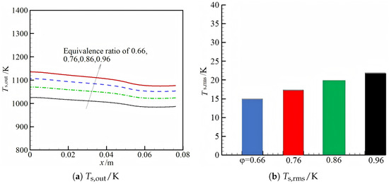
Figure 7 shows the variation in the heating temperature with the x-axis and its RMS for four different equivalence ratios with a constant volumetric flow rate of 43.5 slm and emissivity of 0.85. As shown in Figure 7a, the heating temperature is increased steadily with the equivalence ratio for the fixed volumetric flow rate and emissivity because of the increased adiabatic combustion with an equivalence ratio of the methane/air mixture. The theoretical combustion temperature is increased from 1775 K to 2191 K with the equivalence ratio increasing from 0.66 to 0.96. Correspondingly, the average heating temperature is increased from 1004 K to 1104 K. The variation trend of the heating temperature with the x-axis for four different equivalence ratios is very similar, and it is decreased softly with the x-axis.
Figure 7.
The effect of the equivalence ratio on the heating temperature and its root mean square for a volumetric flow rate of 43.5 slm and .
As shown in Figure 7b, the is softly increased from 14.9 K to 21.9 K with an increasing equivalence ratio from 0.66 to 0.96. The increment of 7 K for with the investigated range of the equivalence ratio is rather small, considering the increment of 100 K for the average heating temperature with the equivalence ratio. This indicates that the equivalence ratio has a minor effect on the non-uniformity of the heating temperature and for the fixed volumetric flow rate and emissivity.
3.2.4. Effect of Surface Emissivity on the Heating Temperature and Its RMS
The effect of the surface emissivity on the heating temperature and its root mean square is presented in Figure 8.
Figure 8.
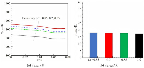
The effect of the emissivity of porous media on the heating temperature and its root mean square for a volumetric flow rate of 43.5 slm and .
As shown in Figure 8, the heating temperature is decreased continually with an increasing surface emissivity, as expected. This is because the radiative output is increased with respect to the surface emissivity for the same operating parameters, resulting in the decrease in the heating temperature versus emissivity. For example, at , the heating temperature is decreased from 1134 K to 1014 K with increasing emissivity from 0.55 to 1.0. Meanwhile, the variation trend of the heating temperature with the x-axis for the four different surface emissivities is very similar. The heating temperature is decreased linearly with the x-axis. As shown in Figure 8b, the emissivity has a negligible effect on the RMS of the heating temperature; the is decreased from 17.9 K to 17.4 K with increasing surface emissivity from 0.55 to 1.0. This may be due to the fact that the entire heating temperature is decreased as the surface emissivity is increased. Meanwhile, the variation trend of the heating temperature along the axis direction is very similar for the four different emissivities, as shown in Figure 8a; thus, the is almost kept unchanged with emissivity.
3.2.5. Effect of Thermal Conductivity of Porous Shell on the Heating Temperature and Its RMS
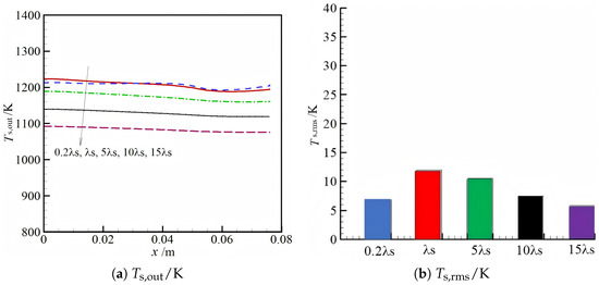
The effect of the thermal conductivity of the porous shell on the heating temperature and its RMS for an emissivity of 0.85 and equivalence ratio of 0.8 is plotted in Figure 9. The reference value of is specified as 4.5 W/m·K.
Figure 9.
The effect of the thermal conductivity of porous media on the heating temperature and its root mean square for a volumetric flow rate of 56 slm, and .
As shown in Figure 9a, the heating temperature along the x-axis for and almost overlaps. However, as the thermal conductivity of the porous shell is further increased from to , the heating temperature versus thermal conductivity is decreased steadily, as shown in Figure 9a. The greater thermal conductivity with the same emissivity leads to a greater radiative output through the burner outlet, as demonstrated in Equation (10), resulting in a lower heating temperature for a greater thermal conductivity. Meanwhile, the gradient of the heating temperature along the axis direction gets smaller with thermal conductivity, as shown in Figure 9a. The greater thermal conductivity of the porous shell is advantageous for the formation of homogeneous temperature distribution within the shell. Thus, a lower temperature gradient is expected for greater thermal conductivity, as shown in Figure 9a. This examination can also be used for the lower with thermal conduction. Greater thermal conductivity leads to more uniform temperature distribution inside the porous shell and also its heating temperature; thus, a lower of the heating temperature is achieved with thermal conductivity, as shown in Figure 9b. For instance, the is decreased from 11.9 K at to 5.8 K at . It may be concluded that the non-uniformity of the could be improved by increasing the thermal conduction of the porous shell. It is noted that the thermal conductivity is extended up to for purely parametric study, and this parameter is overestimated for realistic porous Ni-Al materials.
In all, it is shown in Figure 8 and Figure 9 that the properties of the porous Ni-Al, namely surface emissivity and thermal conductivity, have a significant effect on the heating temperature of the porous shell. The deviations between the predicted and experimental results in Figure 3 can also be attributed to the aforementioned factors. The parametric trends in heating-temperature non-uniformity can be explained by two competing heat-transfer mechanisms: Convective heat transport, dominated by the volumetric flow rate, governs axial temperature decay. Higher flow rates reduce residence time, attenuating axial temperature gradients. Conductive redistribution: within the solid matrix, controlled by the shell’s thermal conductivity, enhances radial heat spreading, mitigating local hot/cold spots. These mechanisms validate the CFD model’s ability to capture key physical processes. For instance, the dominant role of the flow rate and conductivity aligns with theoretical expectations, while the minor influence of emissivity and the equivalence ratio reflects their secondary roles in spatial uniformity. This mechanistic understanding reinforces the reliability of the simulation framework for guiding burner optimization.
4. Conclusions
In this work, the non-uniform heating temperature distribution of a cylindrical porous burner is investigated using a two-dimensional axisymmetric model. The results show that the mass flow rate is non-uniform across the burner sub-outlets, and the heating temperature is also non-uniform along the burner outlet for all investigated parameters. The volumetric flow rate (governing convective transport) and porous shell thermal conductivity (controlling conductive redistribution) are the most influential parameters. The equivalence ratio mainly shifts the overall temperature level, and surface emissivity modulates radiation output, both having secondary effects on uniformity. Therefore, optimizing uniformity should prioritize selecting highly conductive materials and operating at high flow rates, while tuning equivalence ratio and emissivity for other performance objectives. The major conclusions are summarized as follows:
(1) A higher volumetric flow rate leads to a more uniform heating temperature distribution. The decreases from 40 K to 4.4 K as the volumetric flow rate increases from 26.75 slm to 87 slm, under an equivalence ratio of 0.96 and an emissivity of 0.85.
(2) A higher equivalence ratio results in increased heating temperature and greater temperature non-uniformity. However, the resulting 7 K rise in remains relatively small compared to the 100 K increase in average heating temperature at a volumetric flow rate of 43.5 slm and an emissivity of 0.85.
(3) The emissivity of the porous shell has a minor effect on the heating temperature non-uniformity. For a volumetric flow rate of 43.5 slm and an equivalence ratio of 0.76, the decreases from 17.9 K to 17.4 K as the surface emissivity increases from 0.55 to 1.0.
(4) Increasing the thermal conductivity of the porous shell improves the heating temperature uniformity. For a volumetric flow rate of 56 slm, an emissivity of 0.85, and an equivalence ratio of 0.8, the decreases from 11.9 K at to 5.8 K at 15.
This study offers a foundational numerical analysis of heating temperature uniformity in cylindrical porous burners. To build upon these findings, future work should prioritize the following key directions: First, incorporating detailed combustion modeling of the premixed gas within the hollow space is essential. Moving beyond the assumption of pre-combusted products will yield more accurate inlet conditions and enhance the predictive capability of the temperature distribution model. Under this assumption, the flue gas temperature at the burner inlet is considered uniform and equal to the theoretical adiabatic temperature. This evidently overestimates the combustion temperature and may lead to a more uniform temperature distribution at the burner outlet, potentially resulting in a smaller root mean square deviation. Second, further investigation into the coupling between flow non-uniformity and thermal non-equilibrium is needed. A deeper analysis of how the non-uniform mass flow rate at the sub-outlets directly drives the temperature distribution will provide crucial mechanistic insights. Finally, the numerical results presented here warrant comprehensive experimental validation.
Author Contributions
Z.W.: conceptualization, methodology, formal analysis, validation, and writing—original draft; H.L.: methodology, investigation, formal analysis, data curation, and writing—original draft; J.B.: investigation, formal analysis, and validation; H.Y.: data curation and visualization; X.W.: investigation, formal analysis, and visualization; Z.Z.: writing—review and editing, supervision, and funding acquisition; X.Z.: writing—review and editing, and funding acquisition; G.J.: software, supervision, and project administration. All authors have read and agreed to the published version of the manuscript.
Funding
This research was supported by the National Natural Science Foundation of China (No. 51876107) and the Scientific Research Fund of Binzhou Polytechnic University (Grant No. 25-ZJZX-041).
Data Availability Statement
The datasets are made available upon reasonable request to the corresponding author.
Acknowledgments
The authors are grateful to the many colleagues with whom they had the privilege to interact and collaborate with over the years and whose work is partially referenced in this article.
Conflicts of Interest
The authors declare that the research was conducted in the absence of any commercial or financial relationships that could be construed as potential conflicts of interest.
References
- Leonardi, S.A.; Viskanta, R.; Gore, J.P. Radiation and thermal performance measurements of a metal fiber burner. J. Quant. Spectrosc. Radiat. Transf. 2002, 73, 491–501. [Google Scholar] [CrossRef] [Scilit]
- Hashemi, S.A.; Nikfar, M.; Motaghedifard, R. Experimental study of operating range and radiation efficiency of a metal porous burner. Therm. Sci. 2015, 19, 11–20. [Google Scholar] [CrossRef] [Scilit]
- Liu, Y.; Deng, Y.; Shi, J. Experimental investigation on flame stability and emissions of lean premixed methane-air combustion in a developed divergent porous burner. J. Clean. Prod. 2023, 405, 137070. [Google Scholar] [CrossRef] [Scilit]
- Shi, J.; Zhou, D.; Lv, J.; Mao, M.; Ma, X. Self-sustained stable combustion of off-gas from Solid Oxide Fuel Cell in a cone-shaped porous burner with preheaters. Energy 2024, 312, 133566. [Google Scholar] [CrossRef] [Scilit]
- Lv, J.; Shi, J.; Li, J.; Mao, M.; Kong, X. Effect of preheating on extending lean extinction limit of ammonia/air combustion in a two-section porous burner. J. Energy Inst. 2024, 116, 101708. [Google Scholar] [CrossRef] [Scilit]
- Iral, L.; Amell, A. Performance study of an induced air porous radiant burner for household applications at high altitude. Appl. Therm. Eng. 2015, 83, 31–39. [Google Scholar] [CrossRef] [Scilit]
- Weinbrecht, P.; Stelzner, B.; Habisreuther, P.; Weis, C.; Trimis, D. Experimental investigation of irradiance from combustion in porous media with different geometries. Appl. Energy Combust. Sci. 2024, 20, 100294. [Google Scholar] [CrossRef] [Scilit]
- Wieland, C.; Weis, C.; Habisreuther, P.; Trimis, D. 3D direct pore level simulations of radiant porous burners. Combust. Flame 2022, 245, 112370. [Google Scholar] [CrossRef] [Scilit]
- Yakovlev, I.; Pichugin, N.; Astakhov, D.; Zambalov, S.; Maznoy, A. Stabilization hydrogen-air flame in two-section metallic porous burner near lean limit. Int. J. Hydrog. Energy 2025, 138, 1–14. [Google Scholar] [CrossRef] [Scilit]
- Keramiotis, C.; Stelzner, B.; Trimis, D.; Founti, M. Porous burners for low emission combustion: An experimental investigation. Energy 2012, 45, 213–219. [Google Scholar] [CrossRef] [Scilit]
- Vahidhosseini, S.M.; Esfahani, J.A.; Kim, K.C. Assessment of a cylindrical porous radiant burner with internal combustion regime for sustainable energy: Numerical analysis of the radiant efficiency and NO production. Sustain. Energy Technol. Assess. 2021, 43, 100974. [Google Scholar] [CrossRef] [Scilit]
- Fursenko, R.; Maznoy, A.; Odintsov, E.; Kirdyashkina, A.; Minaev, S.; Sudarshan, K. Temperature and radiative characteristics of cylindrical porous Ni-Al burners. Int. J. Heat Mass Transf. 2016, 98, 277–284. [Google Scholar] [CrossRef] [Scilit]
- Maznoy, A.; Kirdyashkin, A.; Minaev, S.; Markov, A.; Pichugin, N.; Yakovlev, E. A study on the effects of porous structure on the environmental and radiative characteristics of cylindrical Ni-Al burners. Energy 2018, 160, 399–409. [Google Scholar] [CrossRef] [Scilit]
- Lee, D.K.; Noh, D.S. Experimental and theoretical study of excess enthalpy flames stabilized in a radial multi-channel as a model cylindrical porous medium burner. Combust. Flame 2016, 170, 79–90. [Google Scholar] [CrossRef] [Scilit]
- Vahidhosseini, S.M.; Esfahani, J.A.; Kim, K.C. Cylindrical porous radiant burner with internal combustion regime: Energy saving analysis using response surface method. Energy 2020, 207, 118231. [Google Scholar] [CrossRef] [Scilit]
- Abdulkarim, A.H.; Ates, A.; Altinisik, K.; Canli, E. Internal flow analysis of a porous burner via CFD. Int. J. Numer. Methods Heat Fluid Flow 2019, 19, 2666–2683. [Google Scholar] [CrossRef] [Scilit]
- Catapan, R.C.; Oliveira, A.A.M.; Costa, M. Non-uniform velocity profile mechanism for flame stabilization in a porous radiant burner. Exp. Therm. Fluid Sci. 2011, 35, 172–179. [Google Scholar] [CrossRef] [Scilit]
- Fluent Inc. Fluent 15.0 User’s Guide; Fluent Inc.: Lebanon, NH, USA, 2006. [Google Scholar]
- Younis, L.B.; Viskanta, R. Experimental determination of the volumetric heat transfer coefficient between stream of air and ceramic foam. Int. J. Heat Mass Transf. 1993, 36, 1425–1434. [Google Scholar] [CrossRef] [Scilit]
- Dey, G.K. Physical metallurgy of nickel aluminides. Sadhana 2003, 28, 247–262. [Google Scholar] [CrossRef] [Scilit]
- Shi, J.; Lv, J.; Behrendt, F.; Liu, Y.; Mao, M.; He, F. 3D pore-scale simulations and 1D volume-averaged calculations of the flow and thermal non-equilibrium for low-velocity filtration combustion. Int. J. Heat Mass Transf. 2021, 177, 121532. [Google Scholar] [CrossRef] [Scilit]
Disclaimer/Publisher’s Note: The statements, opinions and data contained in all publications are solely those of the individual author(s) and contributor(s) and not of MDPI and/or the editor(s). MDPI and/or the editor(s) disclaim responsibility for any injury to people or property resulting from any ideas, methods, instructions or products referred to in the content. |
© 2026 by the authors. Licensee MDPI, Basel, Switzerland. This article is an open access article distributed under the terms and conditions of the Creative Commons Attribution (CC BY) license.