


Abstract
In addressing the key technical challenges of achieving ultra-broadband and high film-thickness uniformity for meter-class large-aperture space telescopes, this study utilized a self-developed 4 m-class large-aperture thin-film deposition system. By employing plasma-assisted electron-beam evaporation technology and a co-evaporation method with inner and outer dual-ring multi-evaporation sources, precise control of film-thickness uniformity within a 2 m range was achieved. A composite film structure combining a metal reflective layer and an ultraviolet-enhanced dielectric layer was adopted to realize high reflectivity across an ultra-broad spectrum from ultraviolet to long-wave infrared. Experimental results show that the average reflectance of the composite film reaches 91.52% in the 0.25~0.38 μm spectral band and 99.40% in the 0.38~12 μm spectral band. The thickness uniformity of ZrO2 and MgF2 films within the 2 m aperture area was controlled at 1.37% and 3.12%, respectively, meeting the requirements for high uniformity in large-aperture space applications. Radiation testing confirmed that the change in film reflectance is less than 1% under a total irradiation dose of 3.66 × 10⁸ rad(Si), satisfying the demands for operation in harsh space environments. This research provides an innovative solution for thin-film technology in large-aperture, ultra-broad-spectrum space optical systems and holds significant value for engineering applications.
1. Introduction
With the ever-increasing demands of modern astronomy for higher precision and broader scope in deep-space exploration, space telescopes are evolving along two core directions: larger apertures and wider spectral coverage. According to the Rayleigh criterion, the angular resolution of an optical system is proportional to its entrance aperture diameter. At a given wavelength, a larger primary mirror diameter enables higher spatial resolution, thereby achieving clearer imaging of distant celestial objects [1,2,3]. Since the successful launch of the Hubble Space Telescope (HST, 2.4 m aperture) in 1990, the vast amount of scientific data it has collected in the visible to near-infrared spectrum has fundamentally transformed our understanding of the universe [4,5,6]. Subsequently, the Spitzer Space Telescope (0.85 m) extended the observational frontier into the infrared. The launch of the James Webb Space Telescope (JWST, 6 m) in 2021 further pushed the boundaries of large apertures and highly sensitive infrared detection to new heights [7,8,9,10,11,12]. The success of these landmark missions demonstrates that primary mirrors with apertures exceeding one meter have become a key technological characteristic of next-generation space astronomy facilities.
Simultaneously, a single operating band can no longer meet the developmental demands of astronomy. Within the entire electromagnetic spectrum, the optical band ranging from ultraviolet to long-wave infrared serves as a crucial radiation window for observing stars and galaxies [13,14]. For space telescopes, the entire optical spectrum, being free from atmospheric interference, constitutes an exceptionally important observational window. Through observations across this spectral range, astronomers can not only obtain vast amounts of data on the structure and evolution of stars and galaxies but also gather astronomical information related to dark matter and dark energy. Consequently, modern space telescopes generally pursue synergistic observational capabilities covering the full spectrum from ultraviolet to long-wave infrared and even into the terahertz range [15]. On one hand, broad spectral coverage facilitates the acquisition of complete electromagnetic radiation information from target celestial objects. On the other hand, by utilizing a shared primary optical system coupled with multiple backend detectors, system complexity and launch costs can be significantly reduced. Therefore, constructing large-aperture primary mirrors capable of high-efficiency reflection across an ultra-broad spectral range has become one of the core challenges in contemporary space optical system design.
How to ensure high uniformity of film thickness across meter-class and larger apertures constitutes a crucial yet often overlooked key challenge in the development of large-aperture space telescopes. Non-uniformity in film thickness directly leads to spatial variations in reflectivity, causing differences in optical gain across different regions of the primary mirror. This ultimately results in severe impacts such as degraded telescope imaging quality, reduced resolution, and decreased contrast. Traditional coating equipment for small apertures (typically less than 1 m) often employs mechanical uniformity correction baffles to regulate the deposition distribution of film thickness, achieving film-thickness uniformity control within <±1%. However, when the aperture expands to 2 m or larger, the traditional baffle method faces multiple impracticalities: First, the structural dimensions of the baffles become enormous, making their manufacturing, installation, and precise positioning extremely difficult. Secondly, during prolonged deposition processes, the baffles themselves are prone to deformation, leading to inaccuracies in thickness adjustment and, conversely, introducing new non-uniformities. Additionally, the shadowing effect of the baffles significantly reduces material utilization, increasing process costs and uncertainty. Therefore, this method is no longer applicable in large-aperture thin-film deposition scenarios. In initial experiments, when relying on a self-developed 4 m-class optical coating system and using a traditional single evaporation source for deposition, the film layer non-uniformity was as high as ±8%, seriously affecting imaging quality and fully exposing the limitations of the conventional approach.
To overcome the aforementioned bottlenecks, this study innovatively proposes a co-evaporation scheme featuring an inner–outer dual-ring multi-evaporation source configuration based on plasma-assisted electron-beam evaporation. This scheme, implemented on a self-developed 4 m-class large-aperture coating system, arranges multiple evaporation source groups in a ring pattern within the vacuum chamber, forming a “concentric dual-ring” layout. By precisely controlling the power, evaporation rates, and activation/cessation sequences of the inner and outer ring evaporation sources, active optimization and dynamic matching of the radial deposition thickness are achieved. This innovative method fundamentally avoids the engineering challenges and performance limitations associated with large physical correction baffles, as it requires no physical masking, thereby enabling the regulation of film uniformity for meter-class large-aperture optical components. Furthermore, based on the design concept of a composite film stack combining a metal reflective layer and an ultraviolet-enhanced dielectric layer, it aims to integrate the high reflectivity characteristics of the silver film with the UV-enhancing effect of the dielectric layers to achieve high reflectivity performance across the entire spectral band.
2. Materials and Methods
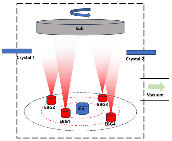
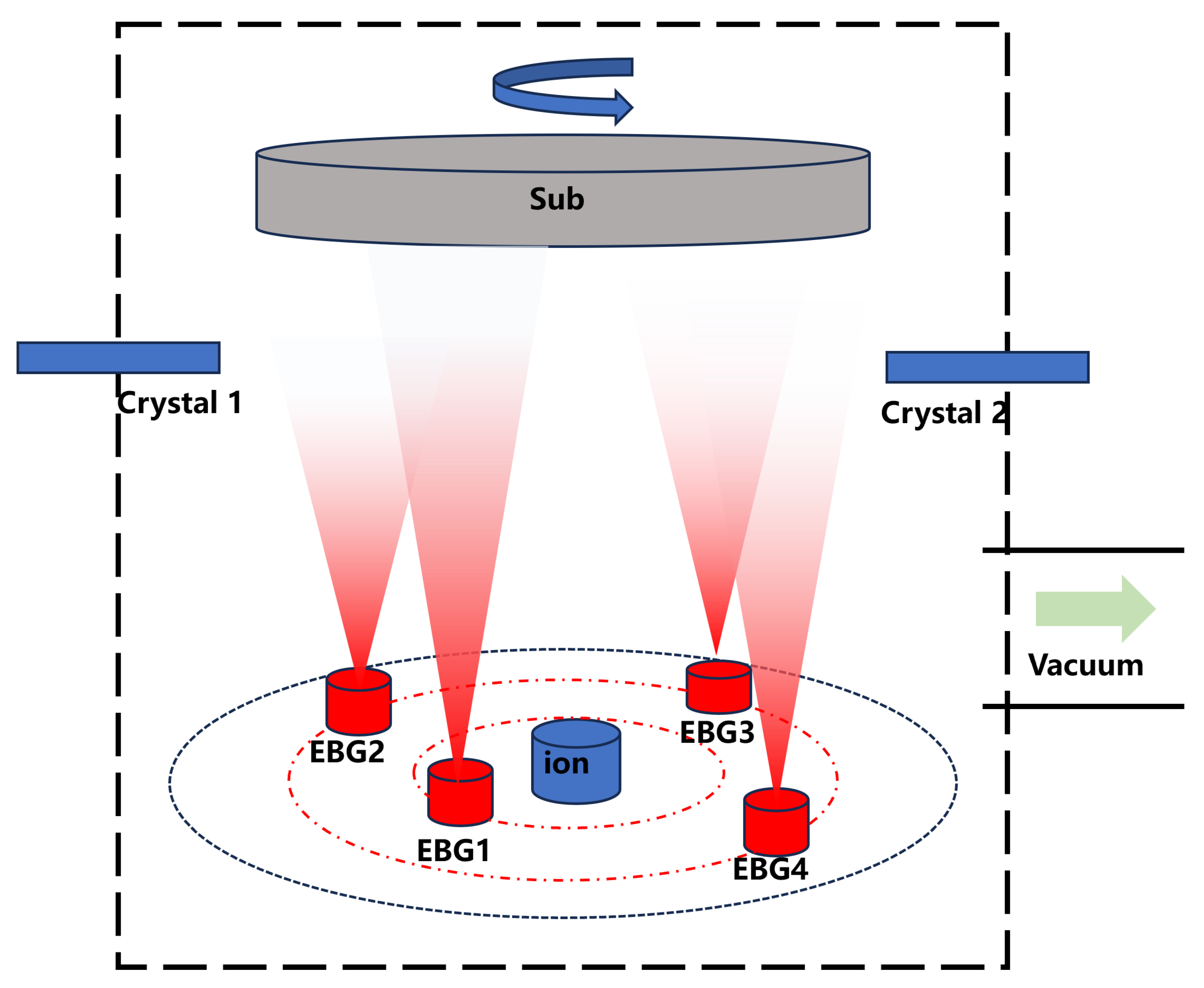
This study was conducted using a self-developed 4 m-class vacuum coating system. Under a base vacuum pressure of 8 × 10⁻⁴ Pa, a composite thin-film structure was fabricated on a silicon carbide substrate employing electron-beam evaporation with the ion beam assistance method. The system features an effective deposition area of 4 m. The vacuum system consists of molecular pumps coupled with oil-free mechanical pumps. Two Polycold units were utilized to significantly enhance the vacuum environment, reduce pump-down time, and prevent contamination. Film thickness was controlled using an Inficon IC6 deposition controller to ensure a layer control precision of up to 0.01 nm. A schematic diagram of the system is shown in Figure 1.
Figure 1.
Schematic diagram of the independently developed 4 M-level electron-beam evaporation equipment.
Silver (Ag) was selected as the metallic reflective layer, while ZrO2 and MgF2 were chosen as the high-refractive-index and low-refractive-index materials, respectively, for the ultraviolet-enhancing dielectric layers. This combination ensures the superior optical performance of the composite coating system across an ultra-broad spectral range. Al2O3 was employed as an adhesion layer material to enhance the mechanical stability and interface quality of the films, thereby ensuring the long-term reliability of the coating system. The detailed information of the materials is shown in Table 1.
Table 1.
Detailed information of materials.
During the deposition process, to accommodate the properties of the large-aperture substrate, the deposition temperature was maintained below 100 °C. The substrate holder rotation speed was set to 30 rpm, and the source-to-substrate distance was fixed at 2.0 m. A dual-ring multi-source co-evaporation configuration was employed, with the positions of the electron-beam guns located at 1 m and 2 m from the center of the chamber, respectively. Ion beam-assisted deposition was performed using an RF ion source. The ion source beam current and voltage were controlled at 1500 mA and 1300 V, respectively. The process gas consisted of a mixture of 70 vol.% Ar and 30 vol.% O2.
After deposition, the physical thickness of the layers was characterized using a spectroscopic ellipsometer (GES5E, Hungarian Semilab Company) at a temperature of 23 °C. The spectral performance of the prepared single-layer and multilayer films was tested using a UV/Vis/NIR spectrophotometer (Lambda 1050, PerkinElmer, Inc., USA) and a Fourier-transform infrared spectrometer. The surface roughness of Ag layers with different thicknesses and the influence of different ion-assisted parameters on film surface defects were characterized using a BRUKER-Dimension Edge atomic force microscope (AFM). The resistance of the coatings to ionizing radiation was evaluated using a Cobalt-60 gamma irradiation test facility to verify their suitability for the space environment (Beijing HTA Jinhui Radiation Technology Co., Ltd., China).
3. Results and Discussion
3.1. Film Layer Structure
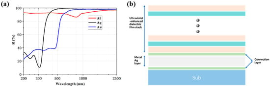
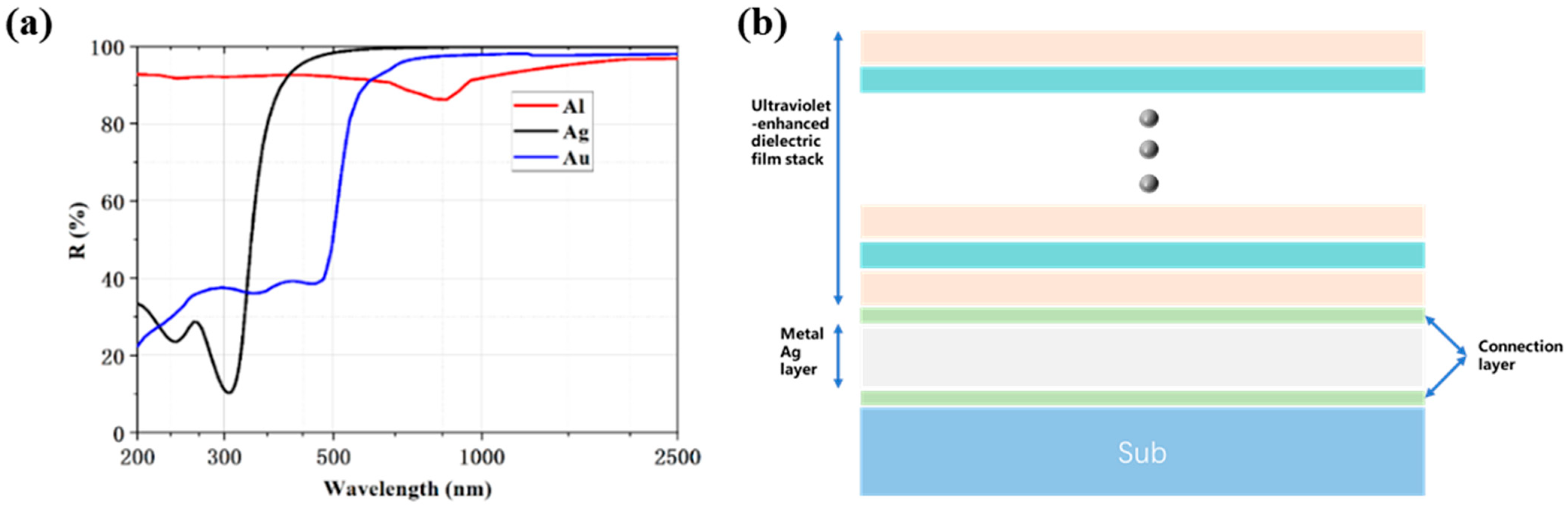
Figure 2a presents the reflectivity of different metallic materials. It can be seen that Au exhibits high reflectivity only at wavelengths longer than 550 nm, which evidently cannot meet the requirements of the optical system in this project. While Al demonstrates relatively high reflectivity in the ultraviolet band, it suffers from a significant reflectivity dip around 800 nm, adversely affecting its performance in the visible and near-infrared regions [16,17,18]. Furthermore, the average reflectivity of Al across various spectral bands is relatively low, resulting in suboptimal total system throughput. Ag maintains consistently high reflectivity over a broad spectral range for wavelengths greater than 350 nm. However, its reflectivity is extremely low (approximately 20%) within the 250–350 nm interval, severely degrading the total system throughput in the ultraviolet region. By comparing the spectral performance and environmental suitability of these three metals, it is concluded that a single metallic layer cannot achieve the required high reflectivity across the broad spectrum from ultraviolet to long-wave infrared. Therefore, to meet the high reflectivity requirement over this wide spectral range, we employ a Ag metallic layer combined with a UV-enhancing dielectric coating [19,20,21,22].
Figure 2.
(a) Reflectivity of different metallic materials. (b) Schematic diagram of the structure combining a Ag metallic layer with UV-enhancing dielectric layers, green represents the connection layer, gray represents the metal layer, and pink and blue represent the alternating deposition of materials with high and low refractive indices. The dots indicates the omission of the middle layer number.
Regarding the selection of dielectric coating materials, to meet the requirements of high transmittance and low absorption from the ultraviolet to long-wave infrared spectral bands, this study considered several dielectric materials suitable for broad spectral applications. Their properties are listed in Table 2. Due to the specific characteristics of the large-aperture substrate, it is necessary to investigate the coating processes under low-temperature conditions. Broad-spectrum, highly transparent fluoride and oxide films are proposed as the low-refractive-index and high-refractive-index dielectric materials, respectively, within the composite coating structure.
Considering the optical properties of oxide and fluoride materials, among the high-refractive-index oxides, Ta2O5 and TiO2 films exhibit good transparency from the visible to long-wave infrared but possess strong absorption in the ultraviolet region, rendering them unsuitable for applications in this band. In contrast, oxide materials such as HfO2, ZrO2, and Gd2O3 demonstrate excellent transparency across the broad spectrum from ultraviolet to long-wave infrared, making them more ideal choices [23,24].
For low-refractive-index materials, fluorides are of significant interest due to their high transparency from ultraviolet to long-wave infrared. Fluoride materials like CaF2, MgF2, and BaF2 exhibit particularly outstanding transparency in the ultraviolet band, and their transparent range can extend into the long-wave infrared region [25,26]. Ultimately, based on their suitability for the low-temperature coating process, this study selected ZrO2 and MgF2 as the high-refractive-index and low-refractive-index materials, respectively, for the ultraviolet-enhancing dielectric layers. This selection ensures the superior optical performance of the composite coating system across an ultra-broad spectral range.
Table 2.
Properties of commonly used dielectric film materials [27].
To enhance the bonding strength between the metal layer and the substrate, as well as between the metal layer and the dielectric layers, this study introduced adhesion layers between these interfaces. These adhesion layers play a crucial role in enhancing bonding strength, mitigating stress caused by differences in coefficients of thermal expansion, and optimizing the optical performance of the coating system. They not only improve the mechanical stability and interface quality of the films but also contribute to optimizing the overall performance within the multilayer structure, serving as a key factor in ensuring the long-term reliability and performance uniformity of the coating system. After comprehensive consideration, Al2O3 was selected as the adhesion layer material in this study [28,29,30]. Based on the ultra-broadband reflectivity specifications and operational lifespan requirements, a coating structure was designed as illustrated in Figure 2b.
3.2. Uniformity of Film Thickness
Film-thickness uniformity is a critical factor determining the optical performance and system reliability of large-aperture components, particularly in high-precision optical systems such as space telescopes [31,32,33]. The film-thickness uniformity reported in this paper is defined by the peak-to-valley (PV) method. Its standard formula is shown in Equation (1).
where , , and are the maximum, minimum, and average thickness values, respectively.
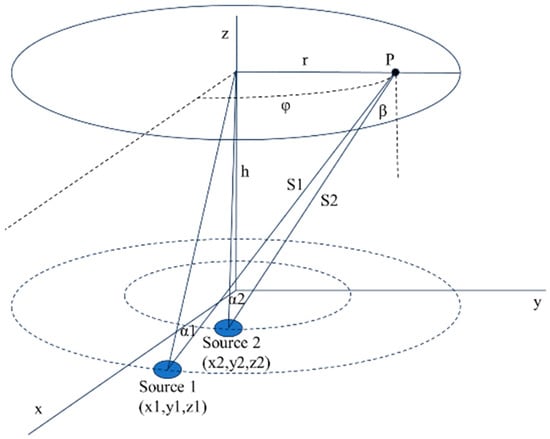
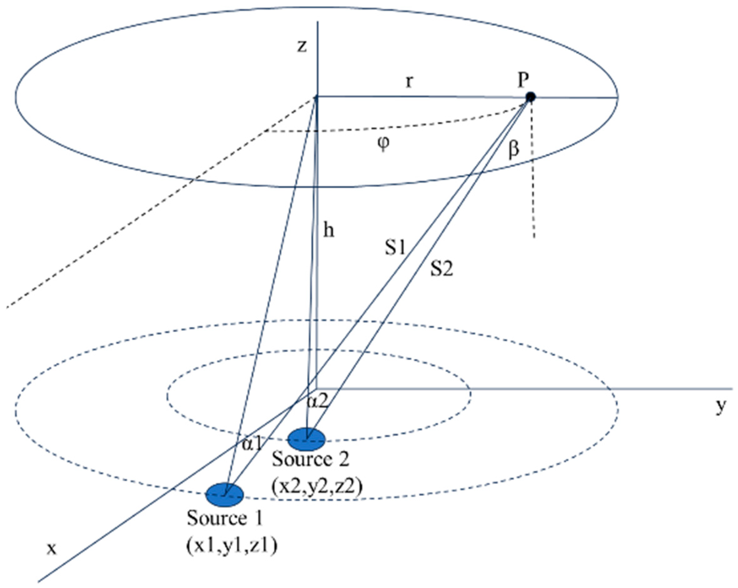
This study utilized a self-developed 4 m-class rotary planar coating system, combining experimental measurements and simulation fitting to analyze the film-thickness distribution. A schematic diagram of the equipment’s geometric configuration is shown in Figure 3.
Figure 3.
Rotating planar evaporation source and substrate geometric configuration.
It is noted that while the thickness uniformity of all layers was controlled, the analysis focuses on the dielectric layer. This is because the optical response of the thin Ag reflector is largely invariant to typical thickness fluctuations (e.g., ±5%), whereas the device performance is critically dependent on the precise optical thickness of the dielectric layer. According to thin-film deposition theory, the film-thickness distribution on a rotating planar substrate can be expressed as follows [34]:
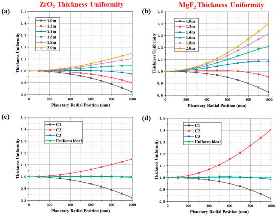
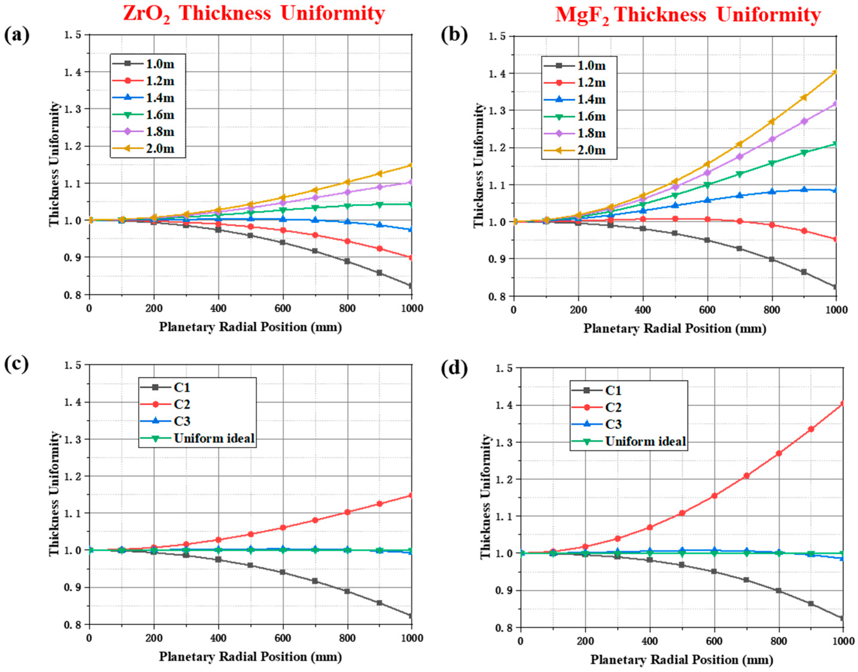
where denotes the thickness at any arbitrary point (P) along the radial direction, r represents the radius at point P, x is the distance from the system center to the evaporation source, h is the evaporation height, and n describes the evaporation characteristics of the electron-beam evaporation source obtained from experiments. Simulation calculations were performed to evaluate the film-thickness uniformity within a 2 m range for evaporation sources at different positions. Figure 4a illustrates the uniformity of ZrO2 films at various positions of the evaporation source within the 1–2 m range, while Figure 4b shows the uniformity of MgF2 films under similar conditions.
Figure 4.
(a) Uniformity of ZrO2 films at different positions of the evaporation source within the 1–2 m range. (b) Uniformity of MgF2 films at different positions of the evaporation source within the 1–2 m range. (c) Simulation results of ZrO2 film deposition using the inner–outer dual-ring configuration. (d) Simulation results of MgF2 film deposition using the inner–outer dual-ring configuration.
Based on the simulation results, a thickness compensation effect is observed when the evaporation source is positioned at 1.0 m and 2.0 m. Accordingly, a co-evaporation deposition mode using inner and outer dual-ring dual evaporation sources is proposed. By adjusting the deposition thickness from different evaporation sources, film-thickness compensation can be achieved, enabling uniform film deposition. Substituting the equipment and process parameters into Equation (2), the thickness distribution for the evaporation source at the 1 m position is given by
The thickness distribution for the evaporation source at the 2 m position is given by
To ensure uniformity, taking ZrO2 as an example and using n = 1.53, we define the combined profile C3 as
where a is the weighting factor. We adjust a so that C3 approaches 1 and determine a by least squares:
Figure 4c shows that for ZrO2 films deposited using the inner–outer dual-ring configuration, the optimal weight factor a is 0.475. This indicates that 47.50% of the single-layer thickness is deposited by the inner ring source and 52.50% by the outer ring source. The resulting best-fit uniformity within the 2 m range is 0.96%. Figure 4d shows that for MgF2 films, with n set to 3.4, the optimal weight factor a for the inner–outer dual-ring deposition is 0.72. This means 72.00% of the single-layer thickness originates from the inner ring source and 28.00% from the outer ring source, achieving a best-fit uniformity of 2.17% within the 2 m range.
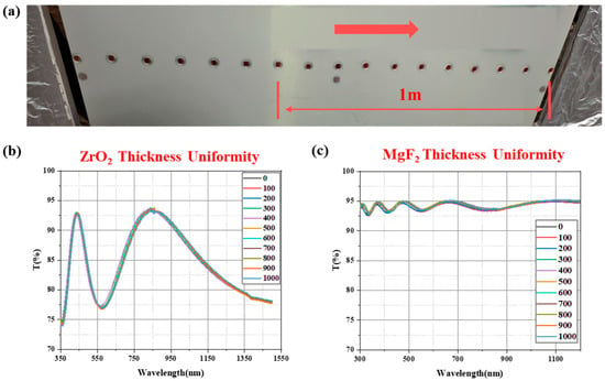
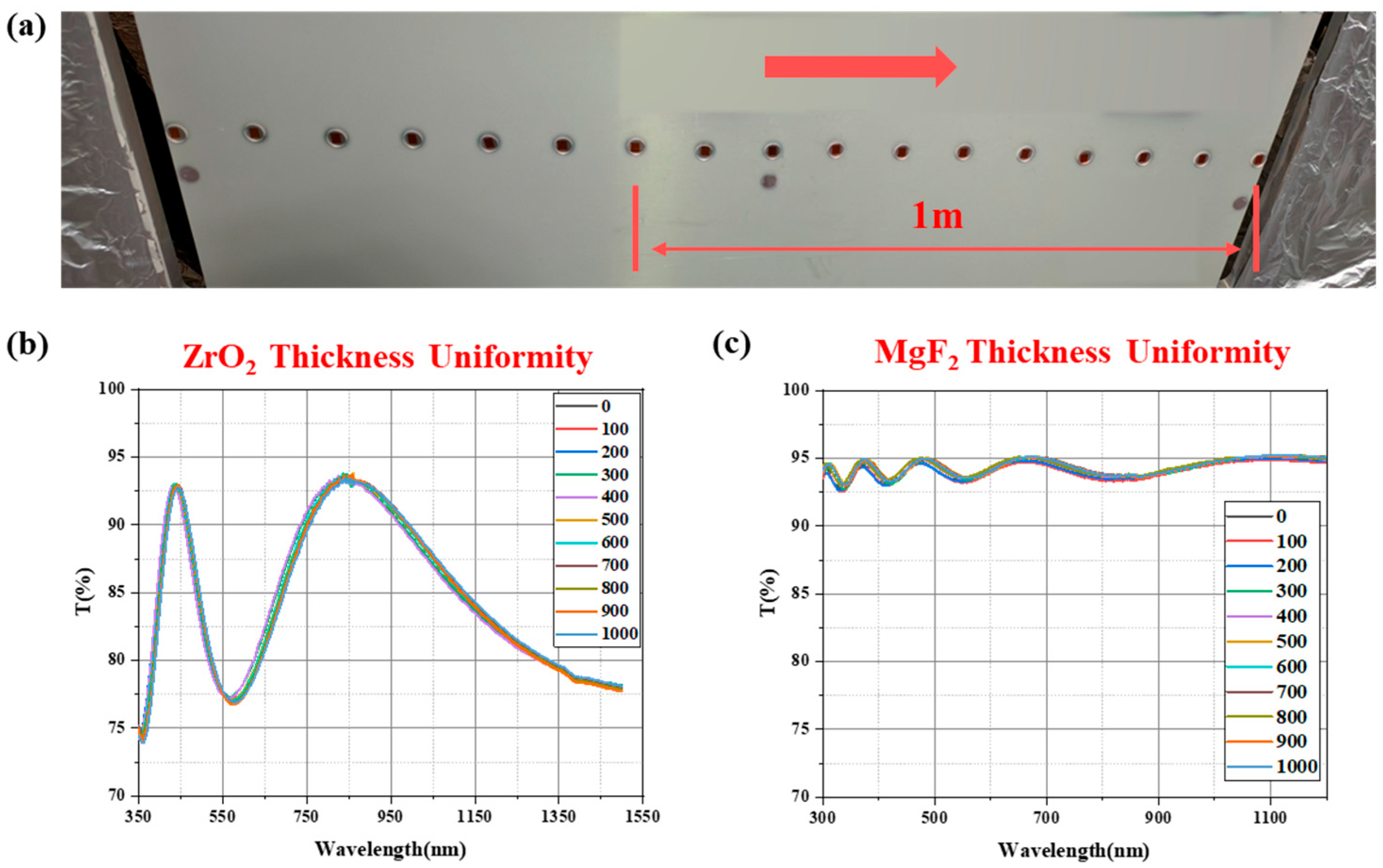
Regarding the uniformity distribution within a 2 m range, quartz glass test pieces were placed at intervals of 100 mm along the radial direction starting from the central zero point, as shown in Figure 5a. The film thickness was measured using an ellipsometer. Figure 5b presents the actual control results for the film-thickness uniformity of ZrO2 films within the 2 m range, while Figure 5c shows the corresponding results for MgF2 films.
Figure 5.
(a) Uniformity test conditions, where the red arrow represents the direction from the center to the periphery. (b) Spectral test results of ZrO2 film-thickness uniformity within a 2 m range. (c) Spectral test results of MgF2 film-thickness uniformity within a 2 m range.
The experimental results indicate that the film-thickness uniformity of ZrO2 films within the 2 m range is 1.37%, and that of MgF2 films is 3.12%. Compared to the simulated values, the measured uniformity is slightly larger. This discrepancy can be attributed to several factors affecting film-thickness uniformity during the deposition process, including the stability of the coating process, variations in evaporation angle, and fluctuations in vacuum level. These factors are difficult to maintain at theoretical stability levels in actual coating processes, leading to deviations between the simulation and experimental results. The more significant discrepancy observed for the MgF2 layer can be attributed to its distinct evaporation behavior and the resulting process sensitivity. Unlike ZrO2, which evaporates congruently from a melt, MgF2 sublimes, necessitating the use of a lower electron-beam current to achieve stable, spit-free deposition. Consequently, the MgF2 deposition process becomes more susceptible to relative fluctuations in vacuum pressure and beam stability, amplifying thickness non-uniformity. Additionally, the optical constants of MgF2 are more sensitive to the deposition rate, further contributing to the error between the simulated optical thickness uniformity and the experimental result.
Despite these deviations, the thickness uniformity of both films is controlled within an acceptable range of ≤±2%, which is crucial for meeting the stringent requirements of space telescope systems. This study provides an effective method and technical support for uniform thin-film deposition on large-aperture optical components, demonstrating significant application value.
3.3. Ion-Assisted Deposition
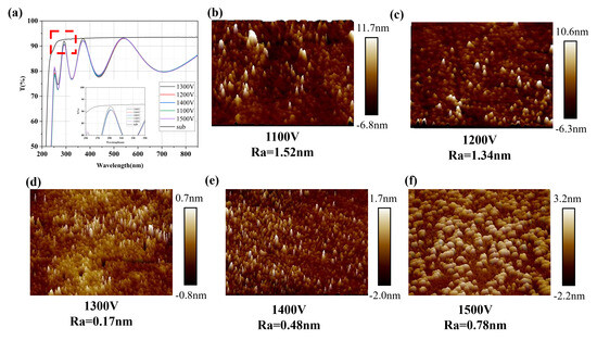
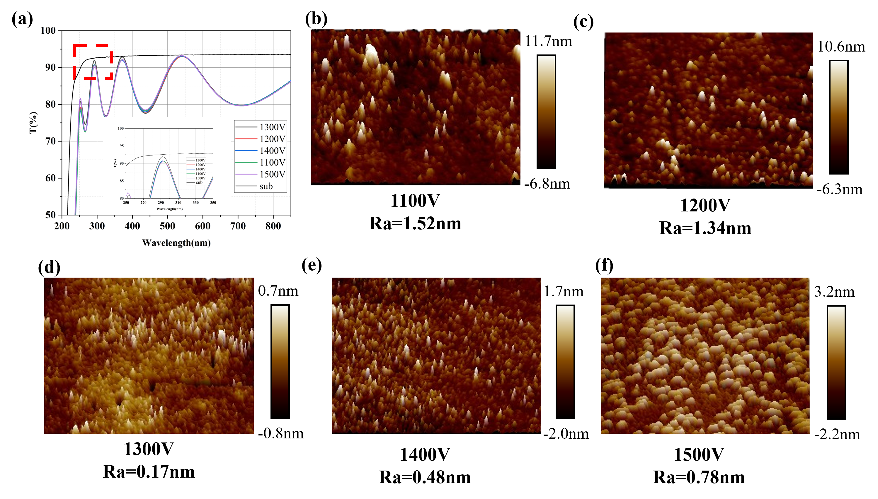
Subsequently, we investigated the effects of different auxiliary ion energies on ZrO2 films. Single-layer ZrO2 films were deposited on quartz substrates, and their spectral performance was characterized using a Lambda 1050 spectrophotometer. Although Figure 6a shows that the transmittance spectra for films deposited at 1200 V and 1300 V are very similar, with both exhibiting high transmittance in the ultraviolet band, a decisive difference was observed in surface morphology.
Figure 6.
(a) Transmission spectra of ZrO2 thin films deposited under different auxiliary ion energies. (b) Surface roughness of ZrO2 thin film deposited at an ion energy of 1100 V. (c) Surface roughness of ZrO2 thin film deposited at an ion energy of 1200 V. (d) Surface roughness of ZrO2 thin film deposited at an ion energy of 1300 V. (e) Surface roughness of ZrO2 thin film deposited at an ion energy of 1400 V. (f) Surface roughness of ZrO2 thin film deposited at an ion energy of 1500 V.
Figure 6b–f presents the corresponding surface roughness characterized by AFM. The root mean square (RMS) roughness was calculated from three random points on each sample, representing the entire surface. The results reveal a clear trend: as the auxiliary ion energy increased from 1100 V to 1300 V, the film roughness decreased significantly, reaching an optimal value of 0.17 nm at 1300 V. In contrast, the film deposited at 1200 V exhibited a much higher roughness of 1.34 nm. This atomically smooth surface achieved at 1300 V is indicative of exceptionally high surface quality, which is crucial for minimizing light scattering losses and ensuring uniform optical properties across the coating.
Therefore, 1300 V was identified as the optimal auxiliary ion energy primarily based on this paramount improvement in surface quality. At this energy, ions retain suitable residual energy upon reaching the substrate, enhancing their mobility to fill voids and increase packing density. This process simultaneously yields superior surface smoothness and high transmittance. Conversely, at higher energies (1400 V and 1500 V), excessive ion bombardment introduces defects, deteriorates roughness, increases absorption, and thus reduces transmittance [35].
3.4. Spectral Performance
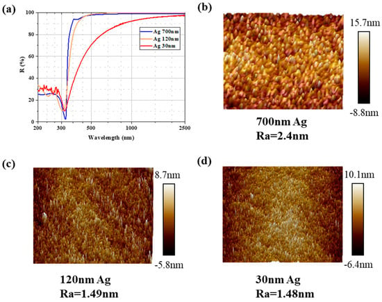
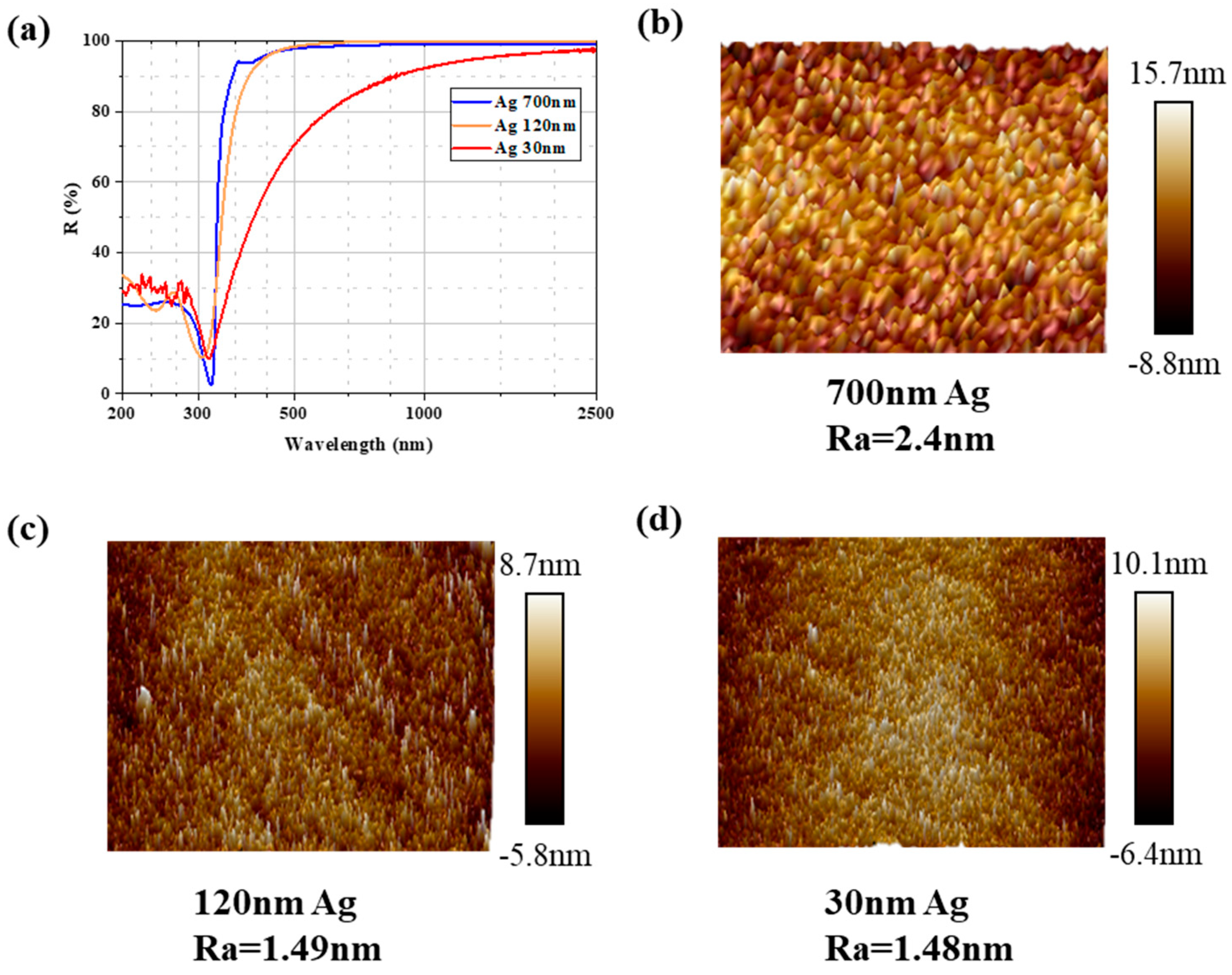
Figure 7a presents the reflectance of metal Ag layers with different thicknesses. For very thin silver films, interference effects may result in relatively low reflectance. When the silver film thickness increases to a certain range (typically between 50 and 150 nm), the reflectance approaches its maximum while transmittance decreases significantly. Beyond this thickness, further increases yield diminishing returns in reflectance enhancement and may introduce issues such as increased roughness, stress, and compromised mechanical stability. Therefore, the surface roughness of single-layer Ag films was measured using atomic force microscopy (AFM) to further investigate the relationship between film thickness and roughness. It was found that film roughness initially decreases and then increases with increasing thickness. Figure 7b–d shows the surface roughness of Ag layers with different thicknesses as measured by AFM.
Figure 7.
(a) Reflectance of metallic Ag layers with different thicknesses. (b) Surface roughness of the 700 nm thick Ag layer. (c) Surface roughness of the 120 nm thick Ag layer. (d) Surface roughness of the 30 nm thick Ag layer.
It was observed that the surface particles of the 700 nm thick film are significantly larger. This is because the initial stage of film deposition fills the roughness profile of the substrate surface, thereby reducing surface roughness. When the Ag film thickness reaches a certain value, its surface roughness becomes approximately equal to that of the substrate. However, with further increases in Ag film thickness, the surface roughness of the Ag film begins to exceed that of the substrate. This is primarily due to the increase in the inherent micro-roughness naturally generated during the film deposition process as the film thickens. Combined with the spectral curves, it is evident that the increased roughness leads to enhanced surface scattering, which is the most pronounced in the ultraviolet band, resulting in a decrease in reflectance. Therefore, the final design selected a deposition thickness of 120 nm for the metallic Ag layer.
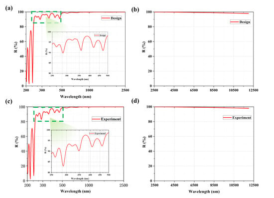
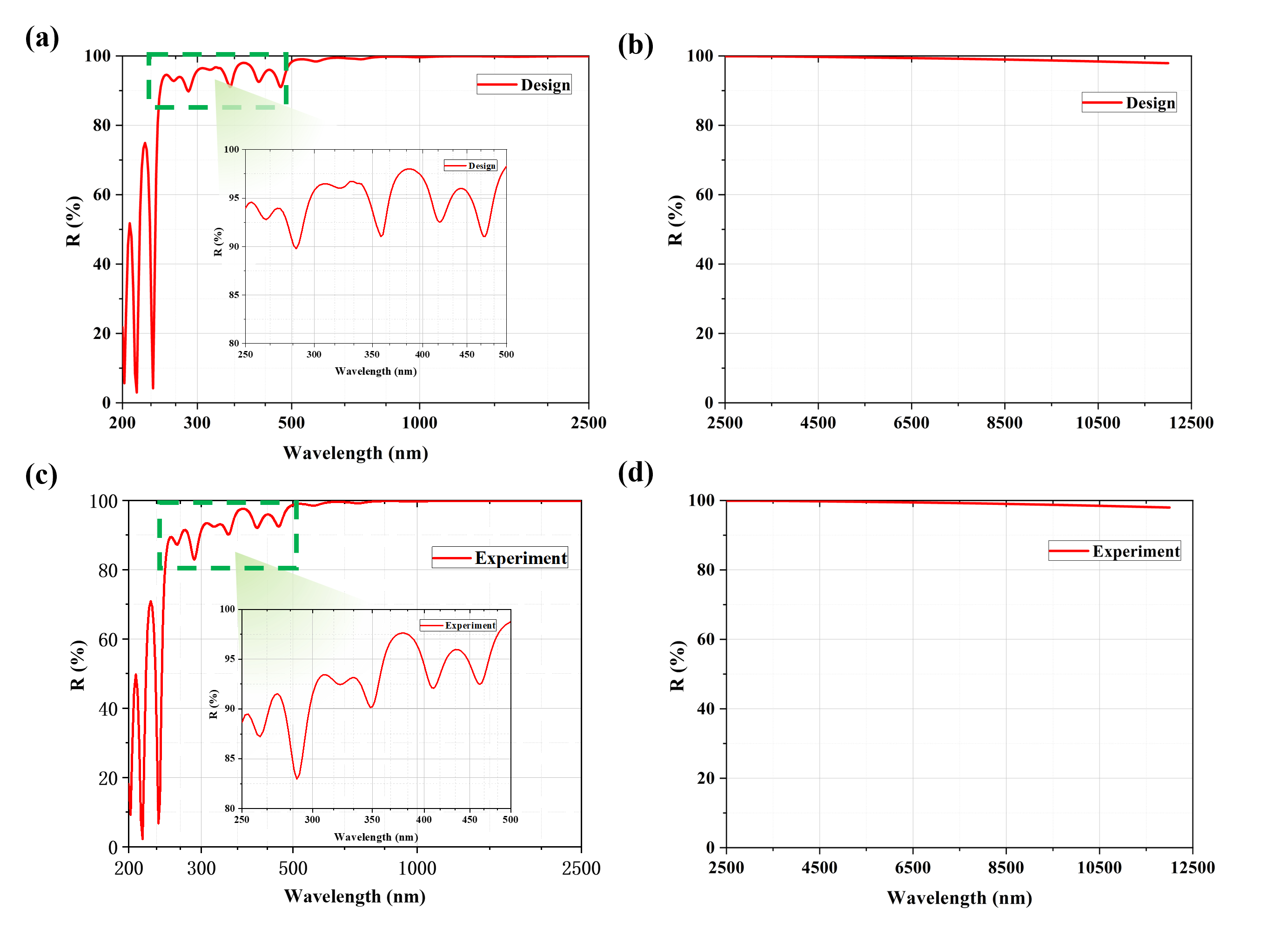
Since the reflectivity of the Ag layer in the ultraviolet band is extremely low, a multilayer dielectric coating is required to enhance reflectivity in this band [36,37]. High-refractive-index ZrO2 and low-refractive-index MgF2 were employed for the enhancement design targeting the 0.25 μm–0.38 μm band. Using the Simplex Parameters method in the Essential Macleod (Version 10.2.491) coating design software with a reference wavelength of 0.25 μm, the number and thickness of the dielectric layers were optimized. Figure 8a,b presents the designed spectral curves, showing an average reflectivity Ra(0.25–0.38μm) = 94.72% in the ultraviolet band and an average reflectivity Ra(0.38–12μm) = 99.40% from the visible to long-wave infrared bands.
Figure 8.
(a) Design curve of the Ag layer combined with UV-enhancing dielectric layers in the UV–NIR band. (b) Design curve of the Ag layer combined with UV-enhancing dielectric layers in the NIR–far-IR band. (c) Measured curve of the Ag layer combined with UV-enhancing dielectric layers in the UV–NIR band. (d) Measured curve of the Ag layer combined with UV-enhancing dielectric layers in the NIR–far-IR band.
Figure 8c,d displays the spectral performance of the fabricated coating as characterized by a Lambda 1050 spectrophotometer. The measured average reflectivity of the fabricated coating is Ra(0.25–0.38μm) = 91.52% in the ultraviolet band and Ra(0.38–12μm) = 99.40% from the visible-to-long-wave infrared bands. It can be observed that random thickness errors introduced during the deposition of the dielectric layers caused a shift between the measured spectral curve and the designed curve. Nevertheless, the reflectivity in the ultraviolet band remains above 90%, meeting the application requirements and simultaneously validating the reliability of the coating structure and its spectral performance.
Based on the aforementioned results, a high-reflectance thin film with ultra-broad spectral coverage from ultraviolet to long-wave infrared for space applications was successfully fabricated using the inner–outer dual-ring co-evaporation method. The measured results demonstrate that the prepared film exhibits an average reflectance of 91.52% in the 0.25–0.38 μm band and an average reflectance of 99.40% in the 0.38–12 μm band. Compared to conventional Ag-only coatings, this composite film significantly improves the reflectance performance in the ultraviolet spectral region, effectively overcoming the inherent deficiency of Ag films in the UV band while satisfying the design requirements for ultra-broadband high-reflectance coatings. The design philosophy and experimental outcomes presented in this study provide a solid foundation for the optical coating design and application in space telescope systems and offer an effective technical pathway for the development of future space telescopes with larger apertures and broader spectral coverage.
3.5. Irradiation Capacity Test
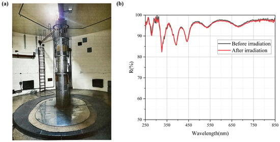
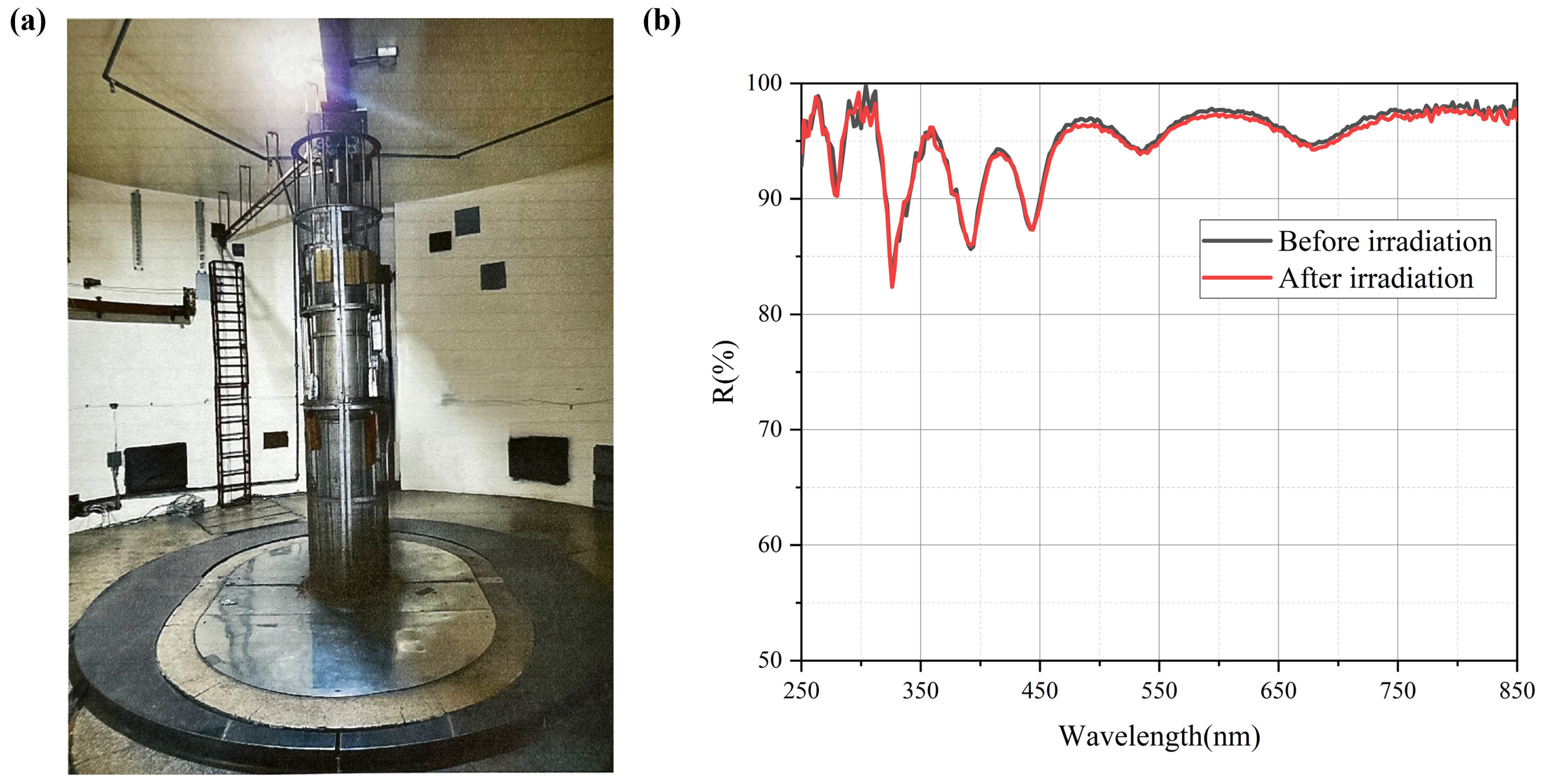
Given the complex radiation environment in space, the film’s resistance to total ionizing radiation dose was evaluated through a total ionizing radiation dose tolerance test. Figure 9a shows the Cobalt-60 gamma irradiation facility. The Cobalt-60 gamma irradiation device has a design capacity of 300,000 curies, with a current activity of 80,000 curies. The irradiation chamber is circular with a diameter of 6.5 m and a height of 3.5 m. At the center is a cylindrical source holder with a diameter of 0.32 m and a height of 2.32 m.
Figure 9.
(a) Cobalt-60 γ-irradiation test facility. (b) Spectral changes in the thin film before and after irradiation.
Figure 9b illustrates the spectral changes in the sample before and after gamma-ray irradiation using the Cobalt-60 facility. It can be observed that when the total ionizing radiation dose reaches 3.66 × 10⁸ rad(Si), the change in reflectance of the silicon-carbide-based reflective coating does not exceed 1%, indicating that it maintains excellent radiation stability. This dose is orders of magnitude higher than what is accumulated in typical low-Earth orbit missions (e.g., on the order of 104 rad over years [38]) and reaches levels relevant to extreme deep-space environments, such as the Jovian system. This indicates that the coating far exceeds the requirements for most Earth-orbit applications and is suitable for long-duration deep-space exploration.
4. Conclusions
Focusing on the requirements for ultra-broadband and high uniformity in meter-class aperture space telescopes, this study successfully designed and fabricated a novel composite thin film, which significantly enhances reflectance in the ultraviolet band and effectively addresses the limitations of traditional silver-based coatings. By combining a Ag layer with ultraviolet-enhancing dielectric layers (ZrO2 and MgF2), an average reflectance of 91.52% was achieved in the 0.25–0.38 μm range and 99.40% in the 0.38–12 μm range. The substantial improvement in ultraviolet reflectance meets the stringent demands for ultra-broadband, high-reflectance coatings in large-aperture space telescope applications. The key innovation of this research lies in the precise control of film-thickness uniformity through an increased number of evaporation sources configured in an inner–outer dual-ring co-evaporation setup. This approach successfully improved the thickness uniformity of ZrO2 and MgF2 films to 1.37% and 3.12%, respectively, within a 2 m range, ensuring the consistency of the films’ optical performance. Furthermore, the coating exhibits outstanding long-term stability under simulated space radiation conditions, providing crucial technical assurance for the high-precision observational capabilities of space telescopes over a 10-year on-orbit operational lifespan. This study lays a solid foundation for the development of meter-class, ultra-broadband, and highly uniform space optical thin films, offering a new pathway for the application of high-performance optical coatings in advanced astronomical instruments.
Author Contributions
Conceptualization, H.W. and J.Z.; data curation, H.Y. and X.W.; formal analysis, H.Y. and H.W.; investigation, J.P. and H.W.; methodology, J.Z.; resources, H.Y.; software, Z.L.; validation, T.W. and Z.S.; writing—original draft, H.W.; writing—review and editing, H.W., H.Y. and Z.L. All authors have read and agreed to the published version of the manuscript.
Funding
This work was supported by the National Key R&D Program of China (2022YFB3606100) and the National Natural Science Foundation of China (Grant No. 62475257).
Institutional Review Board Statement
Not applicable.
Informed Consent Statement
Not applicable.
Data Availability Statement
Date are contained within the article.
Conflicts of Interest
The authors declare no conflicts of interest.
References
- Bely, P.Y. The Design and Construction of Large Optical Telescopes; Springer: Berlin/Heidelberg, Germany, 2003. [Google Scholar]
- Brown, R.A.; Burrows, C.J.; Casertano, S.; Clampin, M.; Ebbets, D.C.; Ford, E.B.; Jucks, K.W.; Kasdin, N.J.; Kilston, S.; Kuchner, M.J.; et al. The 4-m space telescope for investigating extrasolar Earthlike planets in starlight: TPF is HST2. In Future EUV/UV and Visible Space Astrophysics Missions and Instrumentation; SPIE: Bellingham, WA, USA, 2003; Volume 4854, pp. 95–107. [Google Scholar]
- Krist, J.E.; Steeves, J.B.; Dube, B.D.; Riggs, A.E.; Kern, B.D.; Marx, D.S.; Cady, E.J.; Zhou, H.; Poberezhskiy, I.Y.; Baker, C.W.; et al. End-to-end numerical modeling of the Roman Space Telescope coronagraph. J. Astron. Telesc. Instrum. Syst. 2023, 9, 045002. [Google Scholar] [CrossRef] [Scilit]
- Jewitt, D.; Hui, M.-T.; Mutchler, M.; Kim, Y.; Agarwal, J. Hubble Space Telescope Observations of the Interstellar Interloper 3I/ATLAS. Astrophys. J. 2025, 990, L2. [Google Scholar] [CrossRef] [Scilit]
- Savino, A.; Weisz, D.R.; Dolphin, A.E.; Durbin, M.J.; Kallivayalil, N.; Wetzel, A.; Anderson, J.; Besla, G.; Boylan-Kolchin, M.; Brown, T.M.; et al. The Hubble Space Telescope Survey of M31 Satellite Galaxies. IV. Survey Overview and Lifetime Star Formation Histories. Astrophys. J. 2025, 979, 205. [Google Scholar] [CrossRef] [Scilit]
- Sun, F.; Helton, J.M.; Egami, E.; Hainline, K.N.; Rieke, G.H.; Willmer, C.N.A.; Eisenstein, D.J.; Johnson, B.D.; Rieke, M.J.; Robertson, B.; et al. JADES: Resolving the Stellar Component and Filamentary Overdense Environment of Hubble Space Telescope (HST)-dark Submillimeter Galaxy HDF850.1 at z = 5.18. Astrophys. J. 2024, 961, 69. [Google Scholar] [CrossRef] [Scilit]
- Hyde, T.T.; Leisawitz, D.T.; Di Pietro, D.A.; Rinehart, S.A. System engineering the Space Infrared Interferometric Telescope (SPIRIT. In UV/Optical/IR Space Telescopes: Innovative Technologies and Concepts III; SPIE: Bellingham, WA, USA, 2007; Volume 6687, pp. 104–115. [Google Scholar]
- Leisawitz, D.; Baker, C.; Barger, A.; Benford, D.; Blain, A.; Boyle, R.; Broderick, R.; Budinoff, J.; Carpenter, J.; Caverly, R.; et al. The space infrared interferometric telescope (SPIRIT): High-resolution imaging and spectroscopy in the far-infrared. Adv. Space Res. 2007, 40, 689–703. [Google Scholar] [CrossRef] [Scilit]
- Chin, G.; Anderson, C.M.; Bergner, J.; Biver, N.; Bjoraker, G.L.; Cavalie, T.; DiSanti, M.; Gao, J.-R.; Hartogh, P.; Harding, L.K.; et al. Single Aperture Large Telescope for Universe Studies (SALTUS): Science Overview. arXiv 2024, arXiv:2405.12829. [Google Scholar] [CrossRef] [Scilit]
- An, H.; Ge, S.; Liu, J.; Lu, Z. Direct Detection of Dark Photon Dark Matter with the James Webb Space Telescope. arXiv 2024, arXiv:2402.17140. [Google Scholar] [CrossRef] [Scilit]
- Jakobsen, P.; Ferruit, P.; de Oliveira, C.A.; Arribas, S.; Bagnasco, G.; Barho, R.; Beck, T.L.; Birkmann, S.; Böker, T.; Bunker, A.J.; et al. The near-infrared spectrograph (nirspec) on the james webb space telescope—I. overview of the instrument and its capabilities. Astron. Astrophys. 2022, 661, A80. [Google Scholar] [CrossRef] [Scilit]
- Doyon, R.; Willott, C.J.; Hutchings, J.B.; Sivaramakrishnan, A.; Albert, L.; Lafrenière, D.; Rowlands, N.; Vila, M.B.; Martel, A.R.; LaMassa, S.; et al. The Near Infrared Imager and Slitless Spectrograph for the James Webb Space Telescope. I. Instrument Overview and In-flight Performance. Publ. Astron. Soc. Pac. 2023, 135, 098001. [Google Scholar] [CrossRef] [Scilit]
- Leisawitz, D.T.; Amatucci, E.G.; Allen, L.N.; Arenberg, J.W.; Armus, L.; Battersby, C.; Bauer, J.M.; Beltran, P.; Benford, D.J.; Burgarella, D.; et al. Origins Space Telescope: Baseline mission concept. J. Astron. Telesc. Instrum. Syst. 2021, 7, 011002. [Google Scholar] [CrossRef] [Scilit]
- Martin, S.R.; Lawrence, C.R.; Redding, D.C.; Mennesson, B.; Rodgers, M.; Hurd, K.; Morgan, R.M.; Hu, R.; Steeves, J.B.; Jewell, J.B.; et al. Next-generation active telescope for space astronomy. J. Astron. Telesc. Instrum. Syst. 2022, 8, 044005. [Google Scholar] [CrossRef] [Scilit]
- Cataldo, G.; Chodas, M.; Dave, P.; Dixit, A.; Hall, S.; Harris, R.; Hayhurst, D.; Hicks, F.; Jewison, C.; Josan-Drinceanu, I.; et al. Tradespace Investigation of a Telescope Architecture for Next-Generation Space Astronomy and Exploration. SSL Report; 13-14. 2014. Available online: http://hdl.handle.net/1721.1/92407 (accessed on 30 January 2026).
- Hattori, Y.; Kitamura, M. Reflected light microscopy of a gold oxide layer formed on a Au film by ultraviolet/ozone treatment. Thin Solid Films 2022, 764, 139631. [Google Scholar] [CrossRef] [Scilit]
- Cinali, M.B.; Coşkun, Ö.D. Optimization of physical properties of sputtered silver films by change of deposition power for low emissivity applications. J. Alloys Compd. 2021, 853, 157073. [Google Scholar] [CrossRef] [Scilit]
- Pratap, D.; Pradhan, J.K.; Ramakrishna, S.A. Experimental observation of Berreman modes in an uniaxial anisotropic nanoporous alumina film on aluminum substrate. Opt. Lett. 2022, 47, 2554–2557. [Google Scholar] [CrossRef] [Scilit]
- Ji, C.; Liu, D.; Zhang, C.; Guo, L.J. Ultrathin-metal-film-based transparent electrodes with relative transmittance surpassing 100%. Nat. Commun. 2020, 11, 3367. [Google Scholar] [CrossRef] [Scilit]
- Martin, P.J.; Sainty, W.G.; Netterfield, R.P. Enhanced gold film bonding by ion-assisted deposition. Appl. Opt. 1984, 23, 2668–2669. [Google Scholar] [CrossRef] [Scilit] [PubMed]
- Stenzel, O. Optical Coatings: Material Aspects in Theory and Practice; Springer: Berlin/Heidelberg, Germany, 2014. [Google Scholar]
- Liu, H.; Wang, B.; Leong, E.S.P.; Yang, P.; Zong, Y.; Si, G.; Teng, J.; Maier, S.A. Enhanced surface plasmon resonance on a smooth silver film with a seed growth layer. ACS Nano 2010, 4, 3139–3146. [Google Scholar] [CrossRef] [Scilit]
- Wu, H.-Y.; Huang, S.-R.; Shih, C.-H.; Hsiao, L.-J.; Chen, H.-W.; Cheng, M.-C.; Hsu, J.-C. Highly reflective silver-enhanced coating with high adhesion and sulfurization resistance for telescopes. Nanomaterials 2022, 12, 1054. [Google Scholar] [CrossRef] [Scilit]
- Wang, X.; Li, Y.; Cai, B.; Zhu, Y. High refractive index composite for broadband antireflection in terahertz frequency range. Appl. Phys. Lett. 2015, 106, 231107. [Google Scholar] [CrossRef] [Scilit]
- Jena, S.; Tokas, R.B.; Thakur, S.; Sahoo, N.K. Optical Dispersion in ZrO2-SiO2 Composite Thin Films Prepared at Different Oxygen Partial Pressures. Trans. Indian Ceram. Soc. 2013, 72, 10–12. [Google Scholar] [CrossRef] [Scilit]
- Farooq, M.; Hutchins, M. Optical properties of higher and lower refractive index composites in solar selective coatings. Sol. Energy Mater. Sol. Cells 2002, 71, 73–83. [Google Scholar] [CrossRef] [Scilit]
- Freund, L.B.; Suresh, S. Thin Film Materials: Stress, Defect Formation and Surface Evolution; Cambridge University Press: Cambridge, UK, 2004. [Google Scholar]
- Lin, Z.; Song, C.; Liu, T.; Shao, J.; Zhu, M. Comparative Study of Plasma-Enhanced-Atomic-Layer-Deposited Al2O3/HfO2/SiO2 and HfO2/Al2O3/SiO2 Trilayers for Ultraviolet Laser Applications. ACS Appl. Mater. Interfaces 2024, 16, 31756–31767. [Google Scholar] [CrossRef] [Scilit] [PubMed]
- Paul, M.; Morris, B.; Weinhold, J.; Hausmann, K. The effect of stretching and tie layer composition on adhesion strength of multi-layered films. J. Plast. Film Sheeting 2022, 38, 351–368. [Google Scholar] [CrossRef] [Scilit]
- Kamykowski, G.W. Factors affecting adhesion of tie layers between polypropylene and polyamides. J. Plast. Film Sheeting 2000, 16, 237–246. [Google Scholar] [CrossRef]
- Ohlídal, I.; Vohánka, J.; Buršíková, V.; Šulc, V.; Šustek, Š.; Ohlídal, M. Ellipsometric characterization of inhomogeneous thin films with complicated thickness non-uniformity: Application to inhomogeneous polymer-like thin films. Opt. Express 2020, 28, 36796–36811. [Google Scholar] [CrossRef] [Scilit]
- Pan, J.; Zhang, D.; Liu, S.; Wang, J.; Shao, J. Optimization of Film Thickness Uniformity in Hemispherical Resonator Coating Process Based on Simulation and Reinforcement Learning Algorithms. Coatings 2025, 15, 700. [Google Scholar] [CrossRef] [Scilit]
- Wu, Y.; Liu, K.; She, P.; Li, J. Simulation and optimization of reactor airflow and magnetic field for enhanced thin film uniformity in physical vapor deposition. Microelectron. Eng. 2025, 296, 112294. [Google Scholar] [CrossRef] [Scilit]
- Wang, B.; Fu, X.; Song, S.; Chu, H.O.; Gibson, D.; Li, C.; Shi, Y.; Wu, Z. Simulation and Optimization of Film Thickness Uniformity in Physical Vapor Deposition. Coatings 2018, 8, 325. [Google Scholar] [CrossRef] [Scilit]
- Pan, Y.; Yang, C. Effect of incident deposition angle on optical properties and surface roughness of TiO2 thin films. In 8th International Symposium on Advanced Optical Manufacturing and Testing Technologies: Advanced Optical Manufacturing Technologies; SPIE: Bellingham, WA, USA, 2016; Volume 9683, pp. 203–208. [Google Scholar]
- Joseph, K.T.D. Optical and Structural Studies of Silver Oxide Thin Films. Int. J. Thin Film. Sci. Technol. 2025, 14, 57–62. [Google Scholar]
- Xu, G.; Tazawa, M.; Jin, P.; Nakao, S. Surface plasmon resonance of sputtered Ag films: Substrate and mass thickness dependence. Appl. Phys. A 2005, 80, 1535–1540. [Google Scholar] [CrossRef] [Scilit]
- Miteva, R.; Samwel, S.W.; Tkatchova, S. Space Weather Effects on Satellites. Astronomy 2023, 2, 165–179. [Google Scholar] [CrossRef] [Scilit]

Disclaimer/Publisher’s Note: The statements, opinions and data contained in all publications are solely those of the individual author(s) and contributor(s) and not of MDPI and/or the editor(s). MDPI and/or the editor(s) disclaim responsibility for any injury to people or property resulting from any ideas, methods, instructions or products referred to in the content. |
© 2026 by the authors. Licensee MDPI, Basel, Switzerland. This article is an open access article distributed under the terms and conditions of the Creative Commons Attribution (CC BY) license.