


Abstract
Scanning Electrochemical Microscopy represents one of the most advanced high-resolution techniques that enables detailed monitoring of electrochemical processes, with a particular focus on corrosion phenomena. Scanning Electrochemical Microscopy has become an indispensable tool in studying the behavior and degradation of protective coatings exposed to aggressive environmental conditions. This technique allows researchers to precisely track local electrochemical reactions on material surfaces, providing valuable information about the stability and effectiveness of coatings. Scanning Electrochemical Microscopy enables the detection of localized current variations in the pA–nA range, allowing the identification of microdefects with nanometric width. In this paper, the basic principles of Scanning Electrochemical Microscopy operation are first presented, including a description of the device. The method of scanning the electrode is discussed through the modes and their interpretation of the obtained data for systems with protective anticorrosive coatings. Furthermore, Scanning Electrochemical Microscopy techniques enable a detailed study of the mechanisms and kinetics of new, modified coatings, which is especially significant in the case of nanoparticle-enriched coatings. Such modifications often enhance the protective properties of materials, and Scanning Electrochemical Microscopy allows monitoring of their performance under real conditions, providing insight into local electrochemical changes that are otherwise difficult to detect with standard methods. Special attention is given to the challenges researchers may encounter during experiments, such as calibration prior to measurement, interpretation of input parameters, and signal analysis. This paper aims to provide a comprehensive overview of the capabilities and limitations of Scanning Electrochemical Microscopy (SECM), emphasizing its importance as a tool for the development and optimization of new, high-performance coatings for industrial applications and scientific research.
1. Introduction
Scanning Electrochemical Microscopy (SECM) was first introduced in 1989 independently by the research groups of Bard and Engstrom and has since developed into a versatile and powerful analytical technique. Over the past decades, Scanning Electrochemical Microscopy (SECM) has emerged as a powerful and indispensable technique for probing interfacial processes with high spatial and temporal resolution. Its applications span a broad range of phenomena, including corrosion mechanisms, heterogeneous electron-transfer reactions, molecular transport across membranes, adsorption and desorption processes, charge transfer at liquid–liquid interfaces, and the electrochemical activity of living cells. Unlike conventional electrochemical methods, SECM combines electrochemical measurement capabilities with spatially resolved probing [1]. Electrochemical techniques such as cyclic voltammetry, alternating voltammetry, and potentiometry can be employed while simultaneously mapping local variations in electrochemical activity. By combining electrochemical analysis with scanning probe microscopy, SECM enables enhanced characterization of interfaces and local reaction dynamics. In this technique, a microelectrode—typically an ultramicroelectrode—is scanned across the surface of an immersed substrate while the resulting current response is recorded. The magnitude and spatial distribution of this current depend on both the surface topography and the electrochemical reactivity of the substrate. Through this coupling of electrochemical and positional data, SECM provides quantitative insights into heterogeneous processes at the microscale, offering a powerful platform for exploring the structure–activity relationships that govern interfacial phenomena [1,2,3].
To increase stability and extend the service life of epoxy coatings, many researchers are focusing their efforts on their modification. One effective approach involves incorporating nanoparticles into the epoxy coating matrix. Such modification can significantly improve barrier properties, mechanical strength, corrosion resistance, and coating durability under various operating conditions. The morphology of these systems is most analyzed using high-resolution surface techniques such as Scanning Electron Microscopy (SEM), Atomic Force Microscopy (AFM), and SECM. These methods provide detailed insight into the distribution of nanoparticles, their interaction with the polymer matrix, and surface changes caused by different types of modifications.
In their research, Zhao et al. [4] modified an epoxy coating using ZrO2 nanoparticles. SEM analysis showed that the nanoparticles were uniformly dispersed within the epoxy matrix at lower concentrations. However, after adding 2% nano-ZrO2 particles to the epoxy coating, agglomeration was observed, which can negatively affect the homogeneous structure and consequently reduce the mechanical and protective properties of the system. Carolan et al. [5] modified the epoxy coating with silica nanoparticles and core–shell rubber (CRS) nanoparticles. AFM analysis revealed that silica nanoparticles appear on the surface as small yellow dots, while CRS nanoparticles are identified by significantly larger dark circular structures. This difference in morphology clearly indicates the different properties and sizes of the particles used.
While SEM and AFM methods provide detailed insight into surface morphology and passive behavior, SECM analysis is used to examine the electrochemical activity and surface behavior under real conditions. This technique is capable of accurately characterizing microscopic information during the corrosion processes that are localized at specific electrochemically active sites, compared to established electrochemical measurement techniques, such as potentiodynamic polarization curve measurements, cyclic polarization, and electrochemical impedance spectroscopy (EIS), which are limited to detecting the average electrochemical information at the electrode surface [6,7,8].
2. Principle of SECM
2.1. Instrumentation
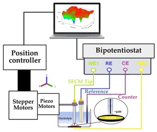
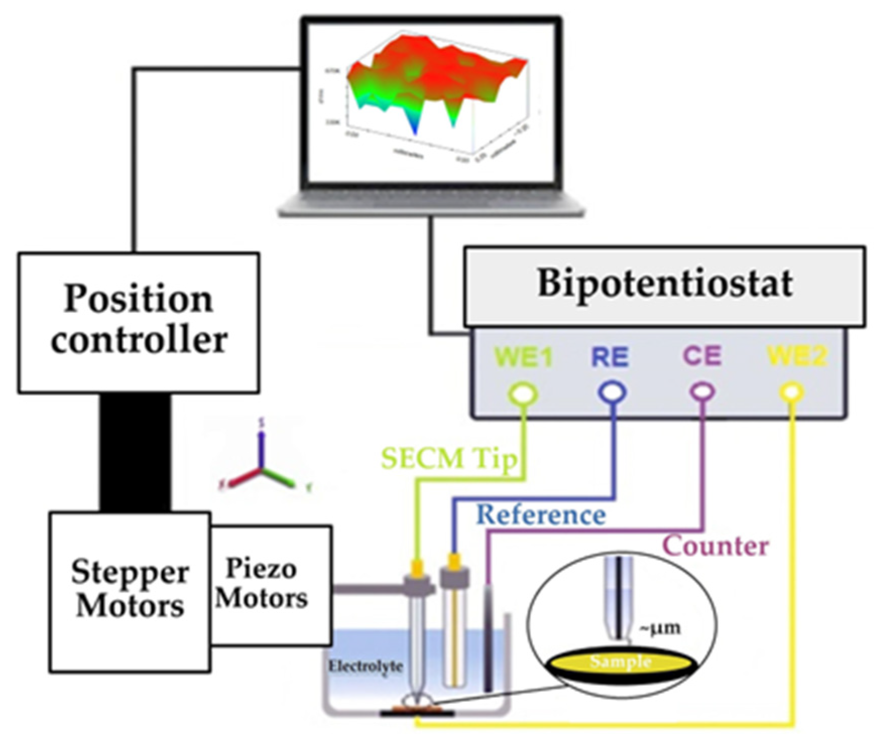
A typical scanning electrochemical microscope comprises several key components (Figure 1). These include a low-current bipotentiostat (≤pA) for precise control and measurement of the probe and substrate potentials and currents, a high-resolution three-dimensional (3D) positioning system with stepper motors for coarse motion and piezoelectric actuators for fine adjustment, and a miniaturized probe with micrometer- to nanometer-scale dimensions (SECM tip). A data acquisition system coordinates all components to enable accurate and reliable measurements [9,10].
Figure 1.
Diagram of the SECM apparatus [11].
The most important component of this electrochemical device is the ultramicroelectrode (UME). In the literature, these sensor elements can also be found under the name probe. At the heart of the SECM is the amperometric or potentiometric UME tip, whose position is controlled remotely, using appropriate positioners, in relation to the sample surface [12]. Their extremely small size plays a key role in the operation of the system, since the UME shows several advantages over electrodes of standard dimensions. First, the small area of the UME allows for very high sensitivity and rapid achievement of a stationary state, which results in a fast system response. In addition, these electrodes are characterized by low double-layer charging currents and minimal ohmic losses, which contribute to the stability and accuracy of measurements. The diameter of the UME directly affects the measurement resolution: the smaller the electrode, the better the resolution, and the more precise the data collected. Also, a smaller electrode area leads to an increase in current density, which results in a larger current signal and a better ability to detect weak electrochemical processes. It is important to note that reducing the dimensions of the electrode also increases sensitivity to noise, so control of instrumental and environmental factors is important for optimal system operation [10,13,14].
SECM is not just another electrochemical method but represents a fundamentally different approach to conducting electrochemistry. In SECM, it is possible to apply almost all types of electrochemical measurements, including direct current (dc) and alternating current (ac) methods, and such measurements can be performed in SECM settings [15]. The device allows for the simultaneous display of two types of information: local reactivity maps (such as current distribution or resistance) and surface topography. To obtain such complementary data, combined techniques such as intermittent contact-direct current Scanning Electrochemical Microscopy (ic-dc SECM) or intermittent contact-alternating current Scanning Electrochemical Microscopy (ic-ac SECM) are used, which allow for precise differentiation of electrochemical and morphological features of the tested material [10,12].
When it is necessary to precisely define a very small reaction volume while preserving a portion of the sample unprotected from the action of the electrolyte, the Scanning Droplet System or Scanning Droplet Cell (SDS/SDC) is used. This technique uses a drop of electrolyte as a localized microreactor, which allows for selective analysis without damaging the surrounding areas. All of the above SECM methods are based on measuring local current or resistance above the surface. In contrast, the Scanning Kelvin Probe (SKP) allows for mapping the surface potential distribution, which is particularly useful in investigating corrosion processes, protective coatings, and differences in the working function potential of materials [10,15]. Table 1 lists the main SECM techniques along with the associated electrode types and their typical diameters.
Table 1.
Presentation of the use of electrodes according to the SECM technique and the corresponding diameter [12,16,17].
2.2. Modes and Analysis of SECM Operation
The SECM device provides a series of analyses of the coating surface in the examination of corrosion processes. Surface analysis is performed using modes that indicate different modes of operation of the UME and different interactions between the UME and the sample. The original concept of SECM was based on positioning a microelectrode (tip) in close proximity to the surface of interest (the substrate) and using the flux of electrochemically active molecules as a probe to visualize the substrate and study its chemical properties [18]. Pilbáth et al. [19] conducted a study on a modified epoxy coating incorporating microcapsules of linseed oil, with the goal of enhancing its protective properties. To evaluate the electrochemical behavior of the coating after mechanical damage, they analyzed the scratched area using the dc-SECM technique. During the analysis, two operating modes of the microscope were employed: the feedback mode and the generation–collection (GC) mode. The condition of the scratched surface was examined by monitoring the oxidation of dissolved Fe2+ (at a tip potential of 0.5 V vs. Ag/AgCl/saturated KCl reference electrode) and the reduction of oxygen (at a tip potential of −0.7 V) in test solutions. The results showed that the oxidation of Fe2+ ions is not an optimal indicator of corrosion processes during prolonged exposure of the coating to the electrolyte, as the current rapidly decreases. The authors attribute this current drop to the possible deposition of corrosion products on the surface, which leads to the blocking of active sites and a reduction in the electrochemical activity of Fe2+ ions. Due to these limitations, Pilbáth et al. [19] proposed an alternative corrosion monitoring approach based on oxygen reduction, as this process provides more stable and reliable signals over longer periods. On the other hand, Xavier [20], in his study focusing on the use of nanoparticles in protective coatings, suggests a combined application of both methods—Fe2+ oxidation and oxygen reduction—in order to obtain a more comprehensive understanding of corrosion and self-healing mechanisms in the coating.
In the review paper by Nazarov and Thierry [21], coatings are analyzed using the SKP technique. SKP is a non-destructive, highly sensitive electrochemical method that measures differences in contact potential between the probe (Etip) and the sample (Esubstrat). The paper presents numerous examples of SKP applications in research, such as studying the effects of pigments, corrosion inhibitors, and surface pretreatments on coating stability, the behavior of different types of paints, and the possibility of quantitatively determining the rate of corrosion propagation beneath the coating.
The method that enables local voltametric and impedance measurements through a controlled microdroplet of electrolyte is known as SDS/SDC. This technique belongs to the group of local electrochemical methods and is used for characterizing surface properties of materials in a very limited solution volume. One of the major advantages of the SDS/SDC method is the minimal sample preparation required. Unlike conventional electrochemical techniques, no electrical contacts need to be formed on the surface, which significantly simplifies the experimental procedure and reduces the possibility of introducing artifacts. Additionally, the use of microvolumes of electrolyte limits the interaction of the solution with the broader surface area, thereby reducing potential material degradation and ensuring very low electrolyte consumption. This enables rapid, localized, and selective investigation of different points on the surface, making the method particularly useful for heterogeneous systems and materials with complex morphology [22]. In the paper by Lohrengel et al. [23], the SDS approach is described in detail, including the experimental configuration, operating principles, and a wide range of potential applications in electrochemical surface studies. A review of the available scientific literature did not reveal any studies explicitly using the SDS/SDC technique for the investigation of epoxy coatings modified with nanoparticles, indicating a promising research area that has not yet been thoroughly explored.
For contextual comparison, the principles and applications of the most used SECM method for studying nanoparticle-based coatings are presented in Table 2.
Table 2.
Basic information and application of SECM methods in the study of coatings for corrosion protection [21,24,25,26,27,28,29,30,31,32,33,34,35,36,37].
According to the data presented in Table 1, SECM is not only a microscopic technique, but a versatile analytical platform that can be combined with different methods to obtain different types of surface information—including chemical activity, topography, and other relevant parameters. Table 1 shows the division of SECM modes into classic and advanced. Depending on the type of experiment and the information we want to obtain, the SECM operating mode is selected. Within dc analytical methods, the device enables the application of techniques such as amperometry, voltammetry, chronoamperometry, and chronopotentiometry, which enables detailed monitoring of electroactive processes on the surface of the sample. Also, combined methods such as ic–dc SECM and ic–ac SECM represent advanced approaches that enable a deeper understanding and more precise characterization of modified surface coatings. The results of these methods can be presented as a two-dimensional (2D) image, corresponding to the operating mode known as depth scan mode. In this mode, the UME moves vertically, enabling depth scanning in the x–z or y–z plane. The depth profile is obtained by performing a series of horizontal line scans nested within the z-approach toward the sample surface. In this way, a 2D current map is generated, where the measured current is shown as a function of the UME position in the (x, z) or (y, z) coordinate system. Such a representation provides a more detailed spatial analysis of the sample’s electrical properties and a clearer insight into signal variations with respect to distance and depth [38]. In 3D view, the UME scans the entire volume in three axes (x, y, z). The scan is performed by a series of 2D (x–y) maps at different z-heights. This way of displaying the results is called hopping imaging mode, XYZ Scan Mode, 3D Mapping Mode, 3D Plot Mode, or 3D SECM map [39]. These methods provide the possibility of simultaneous study of electrochemical and topographical properties, which significantly contributes to the comprehensive analysis of surface processes.
3. Overview of the Most Important SECM Methods for Studying Coatings
3.1. ic-SECM Method
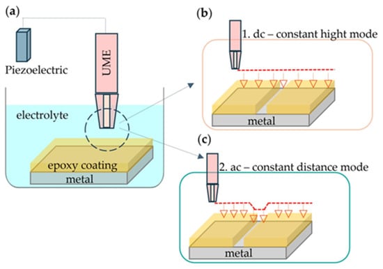
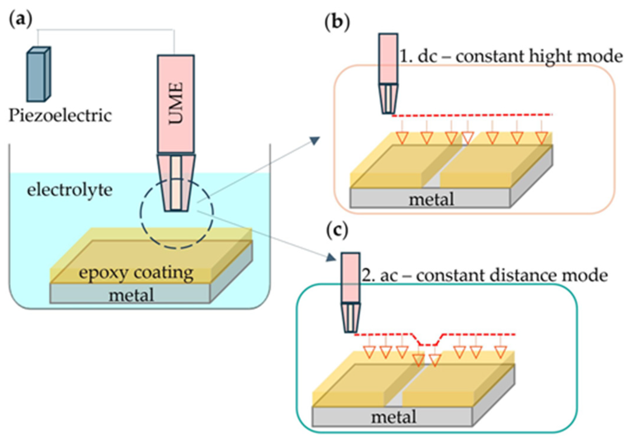
ic-SECM is a completely new method that brings significant improvements compared to conventional SECM techniques. Unlike traditional SECM methods, ic-SECM allows for simultaneous monitoring of the electrochemical activity of the sample while recording its topography during measurements. The operating principle of this method is shown in Figure 2.
Figure 2.
Schematic representation of (a) the electrochemical cell in the ic-SECM method, which operates based on two principles: (b) using direct current and (c) alternating current.
As shown in Figure 2a, the distance of the UME, which is located in the electrolyte, from the sample is controlled using a piezoelectric positioner controller. The piezo attachment allows for fine positioning of the UME very close to the sample surface and control of the distance between the electrode and the surface [40]. Likewise, in some modes (such as ic-SECM) the piezo can vibrate or measure the probe for contact control or distance-controlled imaging. The ic-SECM method operates on two principles, depending on the type of electrochemical signal that we want to measure in interaction with the sample. If we want to observe current changes across the sample surface, we use a direct current (DC) signal in combination with ic-SECM. In this approach, a piezo controller maintains a constant distance between the probe and the sample surface. As shown in Figure 2b, the topography is determined by the distance of the probe from the sample [41]. In contrast, if we want to observe impedance responses across the sample surface, an alternating current (AC) signal is used in combination with ic-SECM. In this method, the piezo controller allows the probe to oscillate relative to the sample surface. As shown in Figure 2c, the probe remains at a constant distance from the sample, meaning that the probe height follows the topographic changes [41].
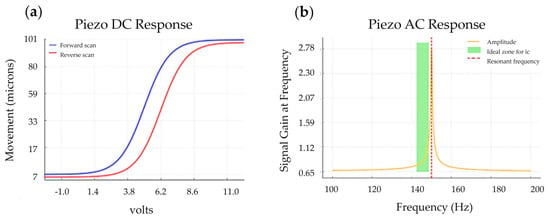
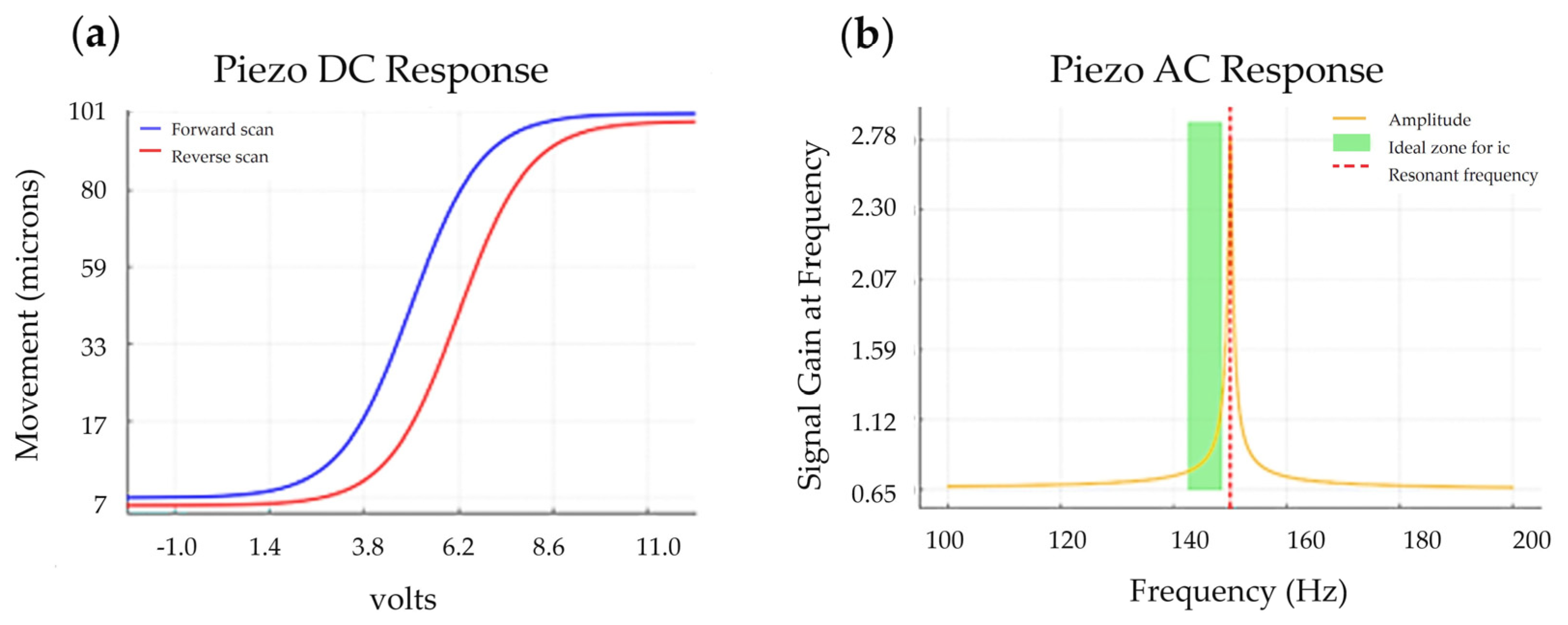
In order to precisely position the UME above the sample surface before performing in situ SECM measurements, it is first necessary to perform a DC piezo-calibration in the range from nanometers to micrometers. DC piezo measurement enables very precise movement of the probe in all three axes (x, y, z) and serves to determine the distance between the tip of the UME and the surface of the sample. In Figure 3a, piezo DC response shows the dependence between the applied voltage and the actual position of the UME. The results show the occurrence of hysteresis, because the piezo actuator does not follow the same path during voltage increase and decrease. This phenomenon can lead to scanning errors, especially at high resolutions, if the hysteresis is not properly compensated through software or hardware correction. Before performing the in situ SECM measurement, it is necessary to perform the AC piezo-calibration. This step makes it possible to determine the optimal frequency and amplitude of oscillations of the piezo element, which ensures a stable and linear response during the measurement. In Figure 3b, the dependence of signal gain at frequency on frequency is shown, which is used to select the frequency at which the system response is most reliable and with minimal signal distortion. Before each measurement, it is necessary to properly adjust the frequency at which the probe oscillations will be stable and regular, using a piezo controller [42,43].
Figure 3.
Calibration measurement of (a) piezo DC response and (b) piezo AC response.
The green zone in Figure 3b indicates the ideal frequency zone for the ic method, usually close to, but slightly below, resonance (≈95–99%). The ideal frequency indicates that the oscillations will be more efficient, which means that maximum sensitivity and stability of the contact interaction with the surface will be obtained. If the frequency of the UME in the intermittent contact mode is not optimally selected, various problems may occur, depending on whether it is too low or too high (Table 3).
Table 3.
UME response to frequencies below and above resonant [44,45].
3.2. dc-SECM Method for Investigation Coating
3.2.1. Principles of ic-dc SECM Technique
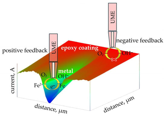
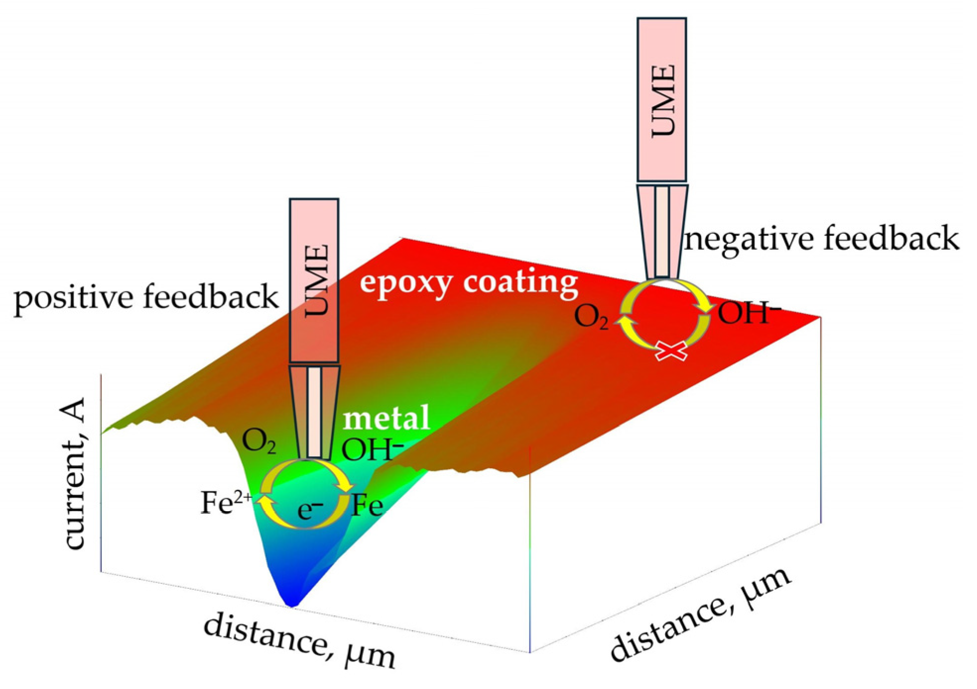
A direct current bias is applied to the UME, which is positioned in close proximity to the sample. This bias interacts with the sample via a redox mediator. The current measured by the probe depends on the interaction of the mediator row with the sample and reflects the relative electrochemical activity of the sample in the area immediately below the probe [46]. This method is most used for the analysis of coatings containing nanoparticles, with the aim of gaining a better understanding of their electrochemical mechanism of action and corrosion protection properties. Before the measurement begins, a pre-prepared protective coating is applied to a 1 cm × 1 cm metal substrate. After a certain drying period—depending on the composition of the coating and environmental conditions—a small scratch is carefully made on the surface of the sample to simulate mechanical damage or initial defects. Depending on the type of mediator to be observed, an appropriate electrochemical solution is selected. The most used solution for testing protective coatings is an aqueous solution of 3.5% NaCl, as sodium chloride is one of the most aggressive components that can accelerate coating degradation and promote corrosion processes. However, during UME measurements, NaCl does not participate directly in the electrochemical reaction due to the applied potential. Under such conditions, the reaction occurs exclusively with the aqueous solution or the metallic substrate. In this method, a constant potential is applied to the UME, which can convert the redox mediator species present in the electrolyte solution [25]. If the reduction of dissolved oxygen above both the undamaged and damaged surface of the sample is to be observed, a potential of −0.7 V vs. AgCl is applied to the UME. A schematic of this measurement is shown in Figure 4, where the reduction of oxygen and iron dissolution on the epoxy surface were observed.
Figure 4.
Schematic representation of positive and negative feedback on a scratched epoxy substrate during ic-dc SECM measurements.
The red areas in Figure 4 represent the undamaged epoxy coating. The epoxy coating is an insulating material, which results in a negative feedback signal during measurement, characteristic of the amperometric feedback mode (U = constant, I ≠ constant). At the very tip of the UME, the reduction of dissolved oxygen from the aqueous solution to hydroxide ions (OH−) occurs, according to the following electrochemical reaction:
O2(g) + 4e− + 2H2O(l) → 4OH−(aq)
However, due to the presence of the insulating epoxy coating, the resulting OH− ions cannot be regenerated, and their diffusion towards the tip of the UME is blocked. As a result, there is a decrease in electrical current and an increase in surface resistance, which confirms the undamaged nature of the coating. On the other hand, in the damaged areas, where the UME comes into contact with the conductive metal substrate, a positive feedback signal is observed. Immersing such a surface in the electrolyte creates potential at the metal/solution interface, which, according to the Nernst equation, depends on the concentration of redox species [25]. In such zones, electrochemical dissolution of iron occurs according to the following reaction:
Fe(s) → Fe2+(aq) + 2e−.
The electrons released during this process can be accepted by dissolved oxygen from the aqueous solution. The resulting oxidation product, O2, diffuses towards the surface of the UME, where it can be further reduced to OH− ions. This phenomenon allows the maintenance of electrochemical activity at the damaged areas, which is reflected by an increase in current and a decrease in resistance compared to the undamaged areas covered by epoxy.
In the review paper by Santana et al. [47], a detailed list of redox mediators used for the examination of various types of coatings on a wide range of materials is provided. The authors provide an overview of the application of specific mediators depending on the type of coating, substrate, and the purpose of the investigation, thereby enabling a better selection of experimental conditions. Coating tests are most often conducted in a simulated corrosive aqueous sodium chloride (NaCl) solution, which is used as a model electrolyte due to its similarity to real corrosive environments. From the tables presented in the study [47], key electrochemical parameters necessary for the proper execution of measurements can be identified, including working potentials, the choice of redox pairs, and optimal experimental conditions. In the case of measuring the concentration of dissolved oxygen (O2) in NaCl solution, an ultramicroelectrode (UME) is used, whose tip is polarized at a potential of −0.70 V relative to an Ag/AgCl/KCl (saturated) reference electrode. At this potential, oxygen is reduced, allowing quantitative monitoring of its concentration in the solution, and thereby assessing the protective properties of the tested coating [47].
When observing the current of iron oxidation on the damaged epoxy surface, the principle is the same, but the potential on the UME is typically around +0.60 V vs. Ag/AgCl.
3.2.2. ic-dc SECM for Investigation of Coating Protection
Traditional methods have long been employed to evaluate protective coatings, but advances in modern coating technologies now demand more sophisticated characterization techniques. Conventional approaches are insufficient to explain the behavior of nanoscale pigments (20–30 nm) or responsive “smart” coatings [48]. In corrosion science, SECM has proven to be a powerful tool for investigating both organic and inorganic metal coatings, enabling applications such as microscopic chemical imaging, measurement of physicochemical parameters, and micromachining.
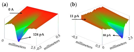
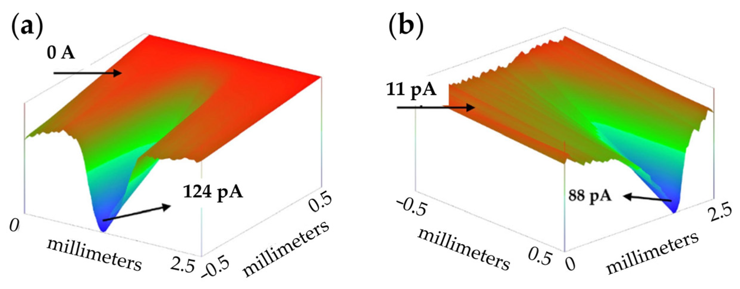
Xavier conducted extensive research on the role of nanoparticles (TiO2, ZrO2, Mg, Ce) in reducing corrosion in epoxy coatings exposed to saltwater [20,49,50]. In the study, a platinum microelectrode was scanned across damaged areas of the coating to monitor dissolved oxygen through the cathodic current. Because oxygen reduction dominates the cathodic corrosion process, changes in dissolved oxygen concentration served as the primary indicator of corrosion activity. The results demonstrated that all nanoparticles reduced the current over damaged regions compared to coatings without nanoparticles, indicating that their presence suppresses iron dissolution from the metal surface. This protective effect is attributed to the formation of surface complexes, which provide additional barrier protection beyond the coating’s inherent film resistance. Madhankumar et al. [51] investigated the behavior of Si nanoparticles (Si NPs) in scratched epoxy-coated samples. SEM and EDS analyses revealed that Si NPs migrated from the coating to the damaged areas over time. It is proposed that Si dissolved as ions (Sin+) and subsequently redeposited at the scratches, providing localized corrosion protection. This behavior indicates a sacrificial effect of Si, enhancing the coating’s ability to protect the underlying steel. Furthermore, Xia et al. [52] examined coating defects using cyclic voltammetry with ferrocenylmethanol as a redox mediator. SECM analysis revealed that defect activity initially increased, reflecting rapid early-stage corrosion of the carbon steel, and later decreased due to the formation of protective corrosion products. Modern SECM instruments allow for the visualization of results in a 3D format, as demonstrated by Kurtela et al. [53]. In their study, they presented 3D results obtained using the ic-dc SECM technique, examining the current distribution on damaged areas of coatings made of pure epoxy (Figure 5a) and coatings modified with graphene oxide (GO) and aluminum nanoparticles (Al NPs) (Figure 5b). This 3D representation clearly shows that higher current densities are observed on the pure epoxy coating, indicating a more pronounced Fe2+ dissolution at the scratch site. In contrast, the presence of GO and Al NP in the coating significantly reduces this process, suggesting improved corrosion protection in the modified samples.
Figure 5.
ic-dc SECM distribution of current of scratched samples of (a) epoxy coating and (b) EP + Al NP + GO sample with cross section immediately after immersed in 3.5 wt% NaCl solution at the tip potential of +60 V vs. Ag/AgCl/KCl reference electrode [53].
3.3. ic-ac-SECM Method for Investigation Coating
For the ic-ac-SECM method, as shown in Figure 2c, it is characteristic that the UME signal, to which the potentiometric method (U ≠ constant) is applied, depends on the distance from the sample. The ic-ac-SECM method provides information about both the topography and electrochemical characteristics of the surface, in contrast to the ac-SECM method, which provides information about the local electroactivity of the sample.
The advantage of using the ac-SECM method over the dc-SECM method lies in the elimination of the need for a redox mediator. While the selection of an appropriate redox mediator is crucial in dc-SECM, special attention must be given when investigating corrosion processes. This is because different electrolytes can significantly affect the outcome of the examination—they may accelerate or inhibit the corrosion process, which can lead to incorrect interpretations of results. In this context, the ac-SECM method presents a superior alternative, as it enables more accurate and reliable measurements without the influence of the redox mediator on the system.
3.3.1. Principles of ac-SECM Technique
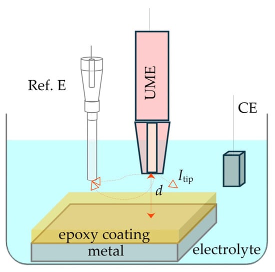
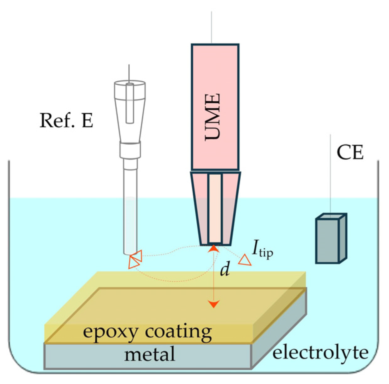
Measurements in the ac-SECM method require the use of a UME, reference electrode, working electrode, and auxiliary electrode. All three electrodes are immersed in the electrolyte, with deionized water being most used due to its low conductivity (Figure 6). The lateral electrochemical contrast in ac-SECM has been found to be highly dependent on the frequency of the applied alternating voltage [54]. An alternating voltage of a specific frequency is applied to the UME, resulting in the appearance of alternating current at the tip of the UME. The current pathway depends on the distance between the UME and the substrate, as well as the type of substrate—whether it is an insulating or conductive surface.
Figure 6.
Schematic representation of ac-SECM technique.
In the case where the distance (d) between the UME and the sample is too large, the current will flow through the solution without interacting with the sample, meaning it will not be directed locally towards the sample. The electric field will extend throughout the entire volume of the solution, and as a result, bulk impedance will be measured.
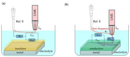
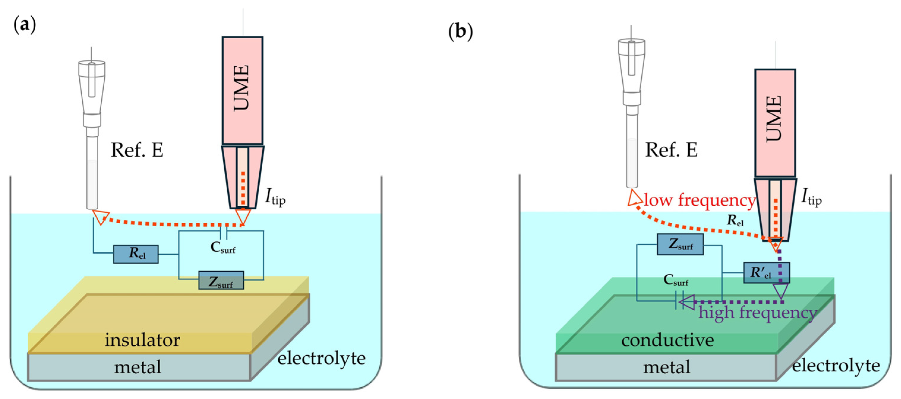
When the UME is at a short distance from the sample, interaction occurs depending on the material of the sample. Figure 7 illustrates the ac-SECM equivalent circuits that describe the overall impedance response on a surface made of insulating and conductive materials. If the sample is an insulator (Figure 7a), the current, Itip, encounters the blocking nature of the sample surface, resulting in a high resistance denoted as Zsurf [55]. Under such conditions, the behavior of the electric circuit can be described by a simple Randles circuit, where the decrease in current leads to an increase in resistance. Since Itip cannot pass through the insulating sample, it is redirected towards the reference electrode.
Figure 7.
Scheme of ac-SECM equivalent circuits on a surface made of (a) insulating and (b) conducting materials.
In the application of the ac-SECM technique, measurements on conductive substrates can be performed at both high and low frequencies. At high frequencies, when the sample is conductive (Figure 7b), the tip current (Itip) flowing from the UME is limited by the resistance of the electrolyte between the UME tip and the sample surface, denoted as (R’e) [56]. In this regime, the current primarily flows capacitively, through charge displacement. This capacitive component of the current is particularly important when studying thin coatings, as it allows for detailed monitoring of changes in layer thickness, porosity, the presence of cracks, and overall uniformity of the coating. In other words, high-frequency measurements provide insight into the physical structure and integrity of the layer without direct contact with the electrically conductive sample, which is crucial for analyzing coatings that are sensitive to mechanical damage or corrosion [47,57].
Unlike measurements at high frequencies, where the current is dominated by accumulation in the electrical double layer, at low frequencies the current primarily depends on the properties of the electrolyte and enters the substrate through an electrochemical reaction, i.e., as faradaic current. In this regime, the current no longer accumulates in the double layer but instead directly follows the kinetics of the electrochemical reactions and the ionic conductivity of the solution [25,42]. In Figure 7b, the Itip current component travels from the top of the UME toward the substrate, where charge transfer occurs, and then spreads further toward the reference electrode, completing the current loop. Such current behavior is characteristic of systems in which faradaic processes dominate over capacitive contributions. In low-frequency measurements, an increase in Faradaic current can indicate the presence of localized corrosion processes beneath a protective coating. The magnitude of this current provides a quantitative insight into the kinetics of metal redox reactions, enabling more precise monitoring of corrosion rates and identification of critical areas particularly susceptible to degradation. Such data are essential for optimizing protective coatings and predicting the service life of metallic structures in aggressive environmental conditions [25,34,54].
3.3.2. ic-ac-SECM for Investigation of Coating Protection
Eckhard et al. [54] conducted ac-SECM testing on a polymer coating sample with defects, over a wide frequency range from 0.273 Hz to 33.199 kHz. The aim of the study was to determine the optimal parameters for achieving high image resolution, thereby improving the accuracy of defect detection and characterization within the coating. In their study, it is observed that as the frequency increases, the defect becomes more confined.
Eckhard et al. [54] report that the surface response investigated at high perturbation frequencies is significantly more constrained compared to lower frequencies, at which capacitive contributions also influence the overall electrochemical signal. Consequently, scratches in the images at frequencies below 1 kHz appear considerably broader.
Wang et al. [58] investigated scratched and self-healed coatings using AC-SECM at both high and low perturbation frequencies. They showed that the AC-SECM images were highly dependent on the probing frequency and the selected portion of the impedance response. At a high frequency (60,000 Hz), the scratch topography was clearly resolved, with minimal influence from surrounding areas. At a low frequency (200 Hz), the scratch remained visible, but the surrounding region was also probed, reducing spatial resolution. An intermediate frequency (3464 Hz) produced results similar to those at high frequency. These findings highlight AC-SECM’s ability to capture a wide range of local electrochemical topographies, enabling detailed observation of self-healing processes at different frequencies.
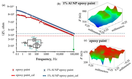
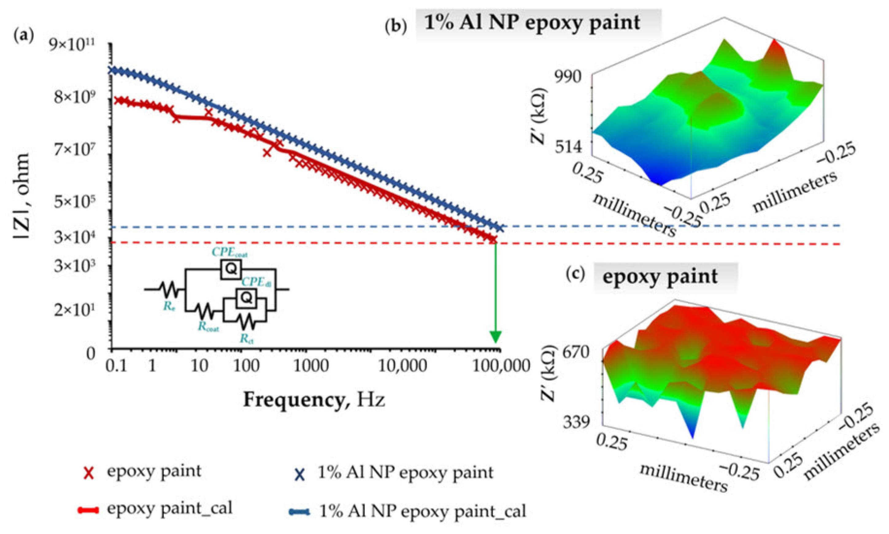
Unlike the previous two authors, Samardžija et al. [11] analyze the influence Al NPs on the anticorrosion properties of an epoxy coating in their study. Their results indicate that the addition of nanoparticles significantly improves the barrier properties of the coating and slows down the penetration of the corrosive medium. Experimental data for the epoxy sample with 1% Al NP content are shown in Figure 8. Figure 8a presents the Bode plot, which clearly shows that the nanocomposite coating exhibits a higher overall resistance and provides better protection compared to the pure epoxy coating after 24 h of exposure to a 3.5% NaCl solution. The authors further expand their analysis of the Bode plots by examining the capacitive properties of the coating at a frequency of 100 kΩ using the ic-ac SECM technique, which enables local mapping of the electrochemical properties of the surface. Figure 8b shows the spatial distribution of impedance values after 1 h of exposure to the solution, while Figure 8c shows the same distribution after 30 days of immersion in the 3.5% NaCl solution. Based on these results, it can be concluded that although the overall impedance values decrease over time due to the gradual degradation process, areas of elevated impedance simultaneously expand. This phenomenon is associated with the formation of an aluminum oxide film on the surface of the nanocomposite, which contributes to additional passivation and slows down the corrosion process.
Figure 8.
Representation of (a) Bode diagram of epoxy coating and 1% Al NP epoxy nanocomposite after 1 h exposure to a corrosive medium, (b) surface topography of a nanocomposite with 1% Al NPs after 1 h exposure to a corrosive medium, (c) surface topography of a nanocomposite with 1% Al NPs after 30 days of exposure to a corrosive medium [11].
4. Conclusions
A review of the available literature confirms that SECM is one of the key and most promising techniques for studying degradation and corrosion processes in epoxy coatings. This paper presents a concise yet comprehensive overview of SECM techniques currently used to examine and interpret the mechanisms of anticorrosion protection in modified coatings. By analyzing various SECM modes and their experimental approaches, the paper provides a clear and structured insight into the acquisition, processing, and interpretation of SECM data.
Through the review of numerous studies, it is emphasized that the incorporation of nanoparticles such as ZrO2, TiO2, CeO2, Mg, Al, SiO2, or graphene oxide (GO) can significantly enhance the barrier properties of coatings, reduce Fe2+ dissolution from the metal substrate, and promote self-healing or passivation processes. Such modifications slow down electrolyte penetration into the coating and contribute to long-term stability and protective performance.
Special attention is given to the importance of proper calibration, with detailed explanations of DC and AC piezo-calibration procedures. The paper also clarifies the critical role of frequency optimization due to its strong influence on image resolution, as well as the challenges that arise at excessively low or high frequencies. This highlights the need for precisely determining the optimal operating conditions of the UME probe to ensure reliability and reproducibility of the acquired data.
Overall, this work provides both a theoretical framework and practical guidelines for the application of SECM in the field of metal protection, clearly demonstrating that this technique enables insight into corrosion processes at spatial and temporal scales beyond the capabilities of standard analytical methods. SECM thus stands out as a highly valuable methodology for the development of advanced, durable, and functional protective coatings.
Author Contributions
Conceptualization, M.S. and V.A.; methodology, M.S. and M.K.; software, M.S. and M.K.; validation, I.S., V.A. and M.K.; formal analysis, M.S.; investigation, M.S., M.K. and I.S.; resources, M.S., M.K. and I.S.; data curation, M.S.; writing—original draft preparation, M.S.; writing—review and editing, M.S.; visualization, M.S.; supervision, V.A., I.S. and M.K.; project administration, V.A.; funding acquisition, V.A. All authors have read and agreed to the published version of the manuscript.
Funding
This research received no external funding.
Institutional Review Board Statement
Not applicable.
Informed Consent Statement
Not applicable.
Data Availability Statement
The data presented in this study are available on request from the corresponding author.
Conflicts of Interest
The authors declare no conflicts of interest.
References
- Polcari, D.; Dauphin-Ducharme, P.; Mauzeroll, J. Scanning electrochemical microscopy: A comprehensive review of experimental parameters from 1989 to 2015. Chem. Rev. 2016, 116, 13234–13278. [Google Scholar] [CrossRef] [Scilit]
- Lillehei, P.T.; Bottomley, L.A. Scanning probe microscopy. Anal. Chem. 2000, 72, 189R–196R. [Google Scholar] [CrossRef] [Scilit]
- Poggi, M.A.; Bottomley, L.A.; Lillehei, P.T. Scanning microscopy. Anal. Chem. 2002, 74, 2851–2862. [Google Scholar] [CrossRef] [Scilit]
- Zhao, X.; Liu, S.; Wang, X.; Hou, B. Surface modification of ZrO2 nanoparticles with styrene coupling agent and its effect on the corrosion behaviour of epoxy coating. Chin. J. Oceanol. Limnol. 2014, 32, 1163–1171. [Google Scholar] [CrossRef] [Scilit]
- Carolan, D.; Ivankovic, A.; Kinloch, A.J.; Sprenger, S.; Taylor, A.C. Toughening of epoxy-based hybrid nanocomposites. Polymer 2016, 97, 179–190. [Google Scholar] [CrossRef] [Scilit]
- Invernizzi, A.J.; Sivieri, E.; Trasatti, S.P. Corrosion behaviour of Duplex stainless steels in organic acid aqueous solutions. Mater. Sci. Eng. A 2008, 485, 234–242. [Google Scholar] [CrossRef] [Scilit]
- Martins, M.; Casteletti, L.C. Microstructural characteristics and corrosion behavior of a super duplex stainless steel casting. Mat. Charact. 2009, 60, 150–155. [Google Scholar] [CrossRef] [Scilit]
- Lo, I.H.; Tsai, W.T. Effect of selective dissolution on fatigue crack initiation in 2205 duplex stainless steel. Corrosi. Sci. 2007, 49, 1847–1861. [Google Scholar] [CrossRef] [Scilit]
- Engstrom, R.C.; Wightman, R.M.; Kristensen, E.W. Diffusional distortion in the monitoring of dynamic events. Anal. Chem. 1988, 60, 652–656. [Google Scholar] [CrossRef] [Scilit]
- Bard, A.J.; Faulkner, L.R. Electrochemical Methods: Fundamentals and Applications, 2nd ed.; John Wiley & Sons Inc.: New York, NY, USA, 2001. [Google Scholar]
- Samardžija, M.; Stojanović, I.; Kurtela, M.; Alar, V. Influence of aluminum nanoparticles in epoxy resin and epoxy coating for anticorrosion and antibacterial protection in pipeline industry. J. Appl. Polym. Sci. 2024, 141, e55002. [Google Scholar] [CrossRef] [Scilit]
- Edwards, M.A.; Martin, S.; Whitworth, A.L.; Macpherson, J.V.; Unwin, P.R. Scanning electrochemical microscopy: Principles and applications to biophysical systems. Physiol. Meas. 2006, 27, R63–R108. [Google Scholar] [CrossRef] [Scilit]
- Dowell, T.J.; Hewage, J.; Wipf, D.O. How to prepare an ultramicroelectrode with a precise geometry. ChemRxiv 2025, 1–19. [Google Scholar] [CrossRef] [Scilit]
- Basha, C.A.; Rajeddran, L. Theories of ultramicrodisc Eelectrodes. Int. J. Electrochem. Sci. 2006, 1, 268–282. [Google Scholar] [CrossRef] [Scilit]
- Mirkin, M.V.; Horrocks, B.R. Electroanalytical measurements using the scanning electrochemical microscope. Anal. Chim. Acta 2000, 406, 119–146. [Google Scholar] [CrossRef] [Scilit]
- Huang, L.; Li, Z.; Lou, Y.; Cao, F.; Zhang, D.; Li, X. Recent advances in scanning electrochemical microscopy for biological applications. Materials 2018, 11, 1389. [Google Scholar] [CrossRef] [Scilit]
- Morkvenaite-Vilkonciene, I.; Ramanaviciene, A.; Kisieliute, A.; Bucinskas, V.; Ramanavicius, A. Scanning electrochemical microscopy in the development of enzymatic sensors and immunosensors. Biosens. Bioelectron. 2019, 141, 111411. [Google Scholar] [CrossRef] [Scilit] [PubMed]
- Mirkin, M.V.; Nogala, W.; Velmurugan, J.; Wang, Y. Scanning electrochemical microscopy in the 21st century. Update 1: Five years after. Phys. Chem. Chem. Phys. 2011, 13, 21196–21212. [Google Scholar] [CrossRef] [Scilit]
- Pilbáth, A.; Szabó, T.; Telegdi, J.; Nyikos, L. SECM study of steel corrosion under scratched microencapsulated epoxy resin. Prog. Org. Coat. 2012, 75, 480–485. [Google Scholar] [CrossRef] [Scilit]
- Xavier, J.R.; Nallaiyan, R. Application of EIS and SECM studies for investigation of anticorrosion properties of epoxy coatings containing ZrO2 nanoparticles on mild steel in 3.5% NaCl solution. J. Fail. Anal. Prev. 2016, 16, 1082–1091. [Google Scholar] [CrossRef] [Scilit]
- Nazarov, A.; Thierry, D. Application of Scanning Kelvin Probe in the study of protective paints. Front. Mater. 2019, 6, 192. [Google Scholar] [CrossRef] [Scilit]
- Joress, H.; DeCost, B.; Hassan, N.; Braun, T.M.; Gorham, J.M.; Hattrick-Simpers, J. Development of an automated millifluidic platform and data-analysis pipeline for rapid electrochemical corrosion measurements: A pH study on Zn-Ni. Electrochim. Acta 2022, 428, 140866. [Google Scholar] [CrossRef] [Scilit]
- Lohrengel, M.M.; Moehring, A.; Pilaski, M. Electrochemical surface analysis with the scanning droplet cell. Fresenius J. Anal. Chem. 2000, 367, 334–339. [Google Scholar] [CrossRef] [Scilit]
- Bard, A.J.; Crayston, J.A.; Kittlesen, G.P.; Vareo Shea, T.; Wrighton, M.S. Digital Simulation of the measured electrochemical response of reversible redox couples at microelectrode arrays: Consequences arising from closely spaced ultramicroelectrodes. Anal. Chem. 1986, 58, 2321–2331. [Google Scholar] [CrossRef] [Scilit]
- Eckhard, K.; Schuhmann, W. Alternating current techniques in scanning electrochemical microscopy (AC-SECM). Analyst 2008, 133, 1486–1497. [Google Scholar] [CrossRef] [Scilit] [PubMed]
- Fayyad, E.M.; Almaadeed, M.A.; Jones, A.; Abdullah, A.M. Evaluation techniques for the corrosion resistance of self-healing coatings. Int. J. Electrochem. Sci. 2014, 9, 4989–5011. [Google Scholar] [CrossRef] [Scilit]
- González-García, Y.; Santana, J.J.; González-Guzmán, J.; Izquierdo, J.; González, S.; Souto, R.M. Scanning electrochemical microscopy for the investigation of localized degradation processes in coated metals. Prog. Org. Coat. 2010, 69, 110–117. [Google Scholar] [CrossRef] [Scilit]
- Kellenberger, A.; Vaszilcsin, N.; Dan, M.L.; Mitelea, I.; Geana, A.A.; Lædre, S.; Craciunescu, C.M. Corrosion investigation by Scanning electrochemical microscopy of AISI 446 and Ti-Coated AISI 446 ferritic stainless steel as potential material for bipolar plate in PEMWE. Acta Metall. Sin. 2024, 37, 607–619. [Google Scholar] [CrossRef] [Scilit]
- Nonnenmacher, M.; O’Boyle, M.P.; Wickramasinghe, H.K. Kelvin probe force microscopy. Appl. Phys. Lett. 1991, 58, 2921–2923. [Google Scholar] [CrossRef] [Scilit]
- Maya-Cornejo, J.; Rodríguez-Gómez, F.J.; Molina, G.A.; Galindo-de-la-Rosa, J.; Ledesma-García, J.; Hernández-Martínez, A.R.; Esparza, R.; Estévez, M. Electrochemical study of a hybrid polymethyl methacrylate coating using SiO2 nanoparticles toward the mitigation of the corrosion in marine environments. Materials 2019, 12, 3216. [Google Scholar] [CrossRef] [Scilit]
- Santana Santos, C.; Jaato, B.N.; Sanjuan, I.; Schuhmann, W.; Andronescu, C. Operando Scanning electrochemical probe microscopy during electrocatalysis. Chem. Rev. 2023, 123, 4972–5091. [Google Scholar] [CrossRef] [Scilit]
- Raj, X.J. Application of EIS and SECM studies for investigation of anticorrosion properties of epoxy coatings containing zinc oxide nanoparticles on mild steel in 3.5% NaCl solution. J. Mater. Eng. Perform. 2017, 26, 3245–3253. [Google Scholar] [CrossRef] [Scilit]
- Souto, R.M.; Lamaka, S.; González, S. Uses of Scanning electrochemical microscopy in corrosion research. In Microscopy: Science, Technology, Applications and Education, 2nd ed.; Méndez-Vilas, A., Díaz, J., Eds.; Formatex: Badajoz, Spain, 2010; Volume 3, pp. 1769–1780. [Google Scholar]
- Traxler, I.; Singewald, T.D.; Schimo-Aichhorn, G.; Hild, S.; Valtiner, M. Scanning electrochemical microscopy methods (SECM) and ion-selective microelectrodes for corrosion studies. Corros. Rev. 2022, 40, 515–542. [Google Scholar] [CrossRef] [Scilit]
- Trentin, A.; Pakseresht, A.; Duran, A.; Castro, Y.; Galusek, D. Electrochemical characterization of polymeric coatings for corrosion protection: A review of advances and perspectives. Polymers 2022, 14, 2306. [Google Scholar] [CrossRef] [Scilit]
- Udhayakumar, M.; Radhika, N.; Arun, K.L. A comprehensive review on nanocrystalline coatings: Properties, challenges and applications. J. Bio. Tribo-Corros. 2022, 8, 83. [Google Scholar] [CrossRef] [Scilit]
- Upadhyay, V.; Battocchi, D. Localized electrochemical characterization of organic coatings: A brief review. Prog. Org. Coat. 2016, 99, 365–377. [Google Scholar] [CrossRef] [Scilit]
- Filice, F.P.; Li, M.S.M.; Wong, J.; Ding, Z. SECM stack imaging and full 3D modelling of asymmetric clusters of live cells. Electrochim. Acta 2025, 538, 146981. [Google Scholar] [CrossRef] [Scilit]
- Lazenby, R.A.; McKelvey, K.; Unwin, P.R. Hopping intermittent contact-scanning electrochemical microscopy (HIC-SECM): Visualizing interfacial reactions and fluxes from surfaces to bulk solution. Anal. Chem. 2013, 85, 2937–2944. [Google Scholar] [CrossRef] [Scilit]
- Putnam, S.T.; Santiago-Carboney, A.; Qian, P.; Rodríguez-López, J. Scanning Electrochemical Microscopy (SECM): An evolving toolbox for revealing the chemistry within electrochemical processes. Anal. Chem. 2025, 97, 8147–8181. [Google Scholar] [CrossRef] [Scilit] [PubMed]
- McKelvey, K.; Edwards, M.A.; Unwin, P.R. Intermittent contact-scanning electrochemical microscopy (IC-SECM): A new approach for tip positioning and simultaneous imaging of interfacial topography and activity. Anal. Chem. 2010, 82, 6334–6337. [Google Scholar] [CrossRef] [Scilit]
- Bard, A.J.; Mirkin, M.V. Scanning Electrochemical Microscopy, 2nd ed.; CRC Press: New York, NY, USA, 2012. [Google Scholar]
- Wipf, D.; Bard, A.J. Scanning electrochemical microscopy. 15. Improvements in imaging via tip-position modulation and lock-in detection. Anal. Chem. 1992, 64, 1362–1367. [Google Scholar] [CrossRef] [Scilit]
- Deng, W. Cantilever Dynamic Analysis in Tapping Mode Atomic Force Microscopy. Ph.D. Thesis, Liverpool John Moores University, Liverpool, UK, April 2015. [Google Scholar]
- Keyvani, A.; Tamer, M.S.; van Wingerden, J.W.; Goosen, J.F.L.; van Keulen, F. A comprehensive model for transient behavior of tapping mode atomic force microscope. Nonlinear Dyn. 2019, 97, 1601–1617. [Google Scholar] [CrossRef] [Scilit]
- Catarelli, S. Scanning electrochemical microscopy: A local view of electrochemistry. Infocus 2020, 57. [Google Scholar] [CrossRef] [Scilit]
- Santana, J.J.; Izquierdo, J.; Souto, R.M. Uses of Scanning electrochemical microscopy (SECM) for the characterization with spatial and chemical resolution of thin surface layers and coating systems applied on metals: A review. Coatings 2022, 12, 637. [Google Scholar] [CrossRef] [Scilit]
- Farrokhpay, S. Application of spectroscopy and microscopy techniques in surface coatings evaluation: A review. Appl. Spectrosc. Rev. 2012, 47, 233–243. [Google Scholar] [CrossRef] [Scilit]
- Xavier, J.R.; Nishimura, T. Evaluation of the corrosion protection performance of epoxy coatings containing Mg nanoparticle on carbon steel in 0.1 M NaCl solution by SECM and EIS techniques. J. Coat. Technol. Res. 2017, 14, 395–406. [Google Scholar] [CrossRef] [Scilit]
- Raj, X.J. Electrochemical investigation into the effect of nano-titania on the protective properties of epoxy coatings on mild steel in natural seawater. Int. Petrochem. Sci. Eng. 2017, 2, 29–37. [Google Scholar]
- Madhankumar, A.; Rajendran, N.; Nishimura, T. Influence of Si nanoparticles on the electrochemical behavior of organic coatings on carbon steel in chloride environment. J. Coat. Technol. Res. 2012, 9, 609–620. [Google Scholar] [CrossRef] [Scilit]
- Xia, D.H.; Wang, J.; Wu, Z.; Qin, Z.; Xu, L.; Hu, W.; Behnamian, Y.; Luo, J.L. Sensing corrosion within an artificial defect in organic coating using SECM. Sens. Actuators. B. Chem. 2019, 280, 235–242. [Google Scholar] [CrossRef] [Scilit]
- Kurtela, M.; Samardžija, M.; Bujak, M.; Stojanović, I.; Bojanić, K.; Ljubek, G. Investigation of corrosion resistance of epoxy coatings reinforced with graphene oxide and aluminium nanoparticle. Rud. Geol. Naft. Zb. 2025, 40, 77–90. [Google Scholar] [CrossRef] [Scilit]
- Eckhard, K.; Erichsen, T.; Stratmann, M.; Schuhmann, W. Frequency-dependent alternating-current scanning electrochemical microscopy (4D AC-SECM) for local visualisation of corrosion sites. Chem. Eur. J. 2008, 14, 3968–3976. [Google Scholar] [CrossRef] [Scilit]
- Liu, D.; Zeng, X.; Liu, S.; Wang, S.; Kang, F.; Li, B. Application of alternating current Scanning electrochemical microscopy in lithium-ion batteries: Local visualization of the electrode surface. ChemElectroChem 2019, 6, 4854–4858. [Google Scholar] [CrossRef] [Scilit]
- Gharbi, O.; Ngo, K.; Turmine, M.; Vivier, V. Local electrochemical impedance spectroscopy: A window into heterogeneous interfaces. Curr. Opin. Electrochem. 2020, 20, 1–7. [Google Scholar] [CrossRef] [Scilit]
- Szociński, M.; Darowicki, K.; Schaefer, K. Application of impedance imaging to evaluation of organic coating degradation at a local scale. J. Coat. Technol. Res. 2013, 10, 65–72. [Google Scholar] [CrossRef] [Scilit]
- Wang, W.; Xu, L.; Sun, H.; Li, X.; Zhao, S.; Zhang, W. Spatial resolution comparison of AC-SECM with SECM and their characterization of self-healing performance of hexamethylene diisocyanate trimer microcapsule coatings. J. Mater. Chem. A 2015, 3, 5599–55607. [Google Scholar] [CrossRef] [Scilit]

Disclaimer/Publisher’s Note: The statements, opinions and data contained in all publications are solely those of the individual author(s) and contributor(s) and not of MDPI and/or the editor(s). MDPI and/or the editor(s) disclaim responsibility for any injury to people or property resulting from any ideas, methods, instructions or products referred to in the content. |
© 2026 by the authors. Licensee MDPI, Basel, Switzerland. This article is an open access article distributed under the terms and conditions of the Creative Commons Attribution (CC BY) license.