


Abstract
18CrNiMo7-6 steel is widely used in high-load mechanical components, but its poor surface hardness and corrosion resistance limit its service life. This study performed vacuum solid boriding treatment on 18CrNiMo7-6 steel at 1000 °C for different times and investigated the phase composition, microstructure, hardness, surface morphology, and corrosion resistance of the resulting boride layers. The experimental results showed that the boriding treatment formed a dual-phase boride layer on the steel surface, consisting of an outer FeB layer and an inner Fe2B layer, both of which increased in thickness with increasing boriding time. The surface hardness was significantly enhanced due to the formation of hard boride phases, exhibiting a gradient distribution that correlates with the microstructural transition from the surface to the substrate. The surface roughness exhibited a progressive increase with boriding time, which was attributed to the volumetric expansion and nodular growth associated with boride formation. Furthermore, the corrosion resistance was remarkably improved after boriding and was further enhanced with longer processing times. This improvement is attributed to the thickening and enhanced continuity of the boride layer over time, which mitigated the potential adverse effects of surface roughness. This study demonstrates that vacuum high-temperature boriding effectively co-enhances the surface hardness and corrosion resistance of alloy steel, providing a viable surface modification strategy for high-load components.
1. Introduction
At present, chemical heat treatment is commonly applied to alloy steel to form functional diffusion layers, thereby enhancing their service performance and lifespan [1,2]. The common chemical heat treatment methods include carburizing, nitriding, boriding, etc., among which boriding has attracted considerable attention from both industry and academia in recent years due to its unique surface strengthening advantages [3,4,5]. Boriding refers to the chemical heat treatment process in which active boron atoms are introduced into the surface of metal material through heating or electrolysis using boron-bearing media [6,7].
The boride layer on alloy steel is usually composed of a single-phase Fe2B or a dual-phase FeB + Fe2B structure, with a thickness exceeding 100 μm, and exhibits excellent surface properties [8,9]. Currently, the boriding processes mainly include solid boriding, salt bath boriding, gas boriding, etc., among which solid boriding is the most widely used [10,11,12]. However, boriding of alloy steel still faces several technical challenges: firstly, the common alloy elements, such as Cr and Mo, significantly inhibit the diffusion of boron atoms [13,14]; secondly, the boriding process has a narrow parameter window and high sensitivity, typically requiring temperatures in the range of 850–1000 °C [15,16]; moreover, a dense passive oxide film tends to form spontaneously on the surface of alloy steels, hindering the adsorption and penetration of active boron atoms into the substrate and substantially reducing boriding efficiency [17,18].
To overcome these technical bottlenecks, vacuum high-temperature boriding has gradually become a focus of research and application. The vacuum environment can completely isolate gaseous impurities and effectively remove the dense oxide film from the substrate surface, thereby eliminating the main barrier to the adsorption and penetration of active boron atoms. Feng et al. studied the interface behavior of stainless steel clad plates under different vacuum degrees and found that when the vacuum degree reaches 10−2 Pa, the oxidation reaction at the cladding interface is significantly inhibited [19]. He et al. revealed the fundamental removal mechanism of Cr2O3 in vacuum high-temperature cladding [20]. Zhang et al. reported results in vacuum cladding of WC/NiCrBSi coatings on 316 L stainless steel. The vacuum environment eliminates gas adsorption at the interface and reduces the diffusion activation energy of alloying elements, leading to a 28% increase in the diffusion depth of Ni, Cr, and B elements compared with atmospheric cladding [21]. Simultaneously, the high-temperature condition significantly reduces the activation energy for boron diffusion in the steel matrix, effectively mitigating the inhibitory effect of strong boride-forming elements, such as Cr and Mo, on the inward diffusion of boron atoms. Thus, vacuum high-temperature boriding represents an efficient technical pathway to address key issues such as insufficient thickness and poor quality stability of boride layers on alloy steels [22,23].
Under typical operating conditions, mechanical components must frequently meet dual requirements for surface strength and corrosion resistance to withstand multiple potential failure mechanisms. If corrosion resistance is compromised in favor of surface strength, such components become susceptible to pitting and spalling, which may ultimately result in failure. Notably, the boride layer not only exhibits surface hardness and wear resistance comparable to those of carburized and nitrided layers but also demonstrates significantly superior corrosion resistance, particularly under harsh environments, including acidic, alkaline, and high-temperature oxidizing conditions [24,25]. Therefore, research on the corrosion resistance of boride layers on alloy steels carries substantial theoretical significance and engineering application value.
However, while the boride layer improves the surface hardness, wear resistance, and corrosion resistance of alloy steel, it often leads to an increase in surface roughness. The surface roughness is a key indicator for evaluating the surface quality of components, directly affecting their assembly accuracy, wear resistance, and corrosion resistance [26,27]. Furthermore, the high hardness of the boride layer makes subsequent processing difficult and costly. If a smoother boride layer can be obtained directly by optimizing the boriding process parameters, post-processing steps can be significantly reduced or even eliminated, thereby improving production efficiency and economic benefits [28,29]. Consequently, how to effectively control the surface roughness of boride layers on alloy steels has become an issue that must be considered in related research.
In view of this, this paper uses 18CrNiMo7-6 steel as the research object, on which the vacuum high-temperature boriding was conducted for different boriding times. The phase composition, microstructure, element distribution, and hardness profile of the boride layer are systematically analyzed. The variation patterns of surface roughness and corrosion resistance of the boride layers with boriding time are investigated, aiming to provide a theoretical basis and practical guidance for optimizing the vacuum high-temperature boriding process.
2. Materials and Methods
The experimental material used in this paper is 18CrNiMo7-6 steel, and its chemical composition is shown in Table 1. 18CrNiMo7-6 steel is typically employed in applications such as large gears and transmission shafts for mining and port machinery. These components do not demand high surface finish yet must exhibit resistance to environmental corrosion [30]. Square specimens with dimensions of 10 mm × 10 mm × 10 mm were prepared. Before boronizing treatment, specimens were ground on 400-mesh SiC paper to make the roughness Sa of the sample approximately 0.4 ± 0.05 µm.
Table 1.
The chemical composition of 18CrNiMo7-6 steel (wt%).
The boronizing agents used in the boronizing process were B4C (10 wt%), KBF4 (10 wt%), and SiC (80 wt%). Among them, B4C was the boron supply agent, KBF4 was the activator, and SiC was the filler. The cup-shaped ceramic crucible employed had a diameter of approximately 40 mm and a height of approximately 50 mm. During the boronizing process, the boronizing agent was ground and screened through a 200-mesh sieve. The sample was placed in the middle of a covered crucible and filled with the boronizing agent before being sealed (it should be ensured that the distance between the sample and the crucible is greater than 5 mm). The entire boriding process, including the heating and cooling, was conducted in a vacuum environment, where the pressure does not exceed 0.1 Pa.
For this steel grade, to enhance boriding efficiency, obtain a boride layer of practical thickness for engineering applications, and systematically investigate the microstructure and growth kinetics of the boride layer, the boriding process was conducted at 1000 °C [31,32]. The heating rate was set to 10 °C/min during the heating stage. The holding time corresponded to the boriding time, which was set to 1 h, 2 h, and 4 h, respectively. After holding, the samples were furnace-cooled to room temperature. For each experimental condition, three parallel samples were prepared independently under identical process parameters.
The surface phase composition of the borided sample was analyzed by X-ray diffraction (PANalytical, Almelo, Germany) using a copper target operated at 45 kV (tube voltage) and 40 mA (tube current), with a scan step of 0.01° over the 20–90° range. The microstructure of the borided sample along the thickness direction was characterized by scanning electron microscopy (Zeiss, Oberkochen, Germany). Prior to observation, the borided sample along the thickness direction was etched with a 4% nitric acid alcohol solution. The distribution of Fe and B elements of the borided sample along the thickness direction was determined by electron probe microanalysis (Shimadzu Corporation, Kyoto, Japan) with a line-scan step of 1 μm.
The hardness distribution of the borided samples along the thickness direction was measured using a Vickers hardness tester (KAID, Beijing, China) under a load of 50 g and a dwell time of 10 s. Measurements were conducted along the direction perpendicular to the borided layer on the cross-section, starting from the surface of the sample toward the core. The initial indent distance from the surface was 20 μm. To ensure that the indentations do not interfere with each other, the indentation spacing along the depth direction was 20 μm, and the lateral spacing was 50 μm. Three sets of data were measured for each diffusion layer, and the average value was used.
The surface morphology and three-dimensional topography were examined by scanning electron microscopy (SEM) and a 3D profilometer, respectively. When measuring the roughness of the samples, Sa, St, and Ssk were selected as the roughness evaluation parameters, and subsequent data processing was carried out using the instrument’s built-in analysis software (Vision64 V5.60). Three distinct areas of the samples were measured, with each area sized at 0.6 mm × 0.6 mm. Finally, the average value of the roughness data from the three areas was used as the representative roughness of the samples.
The corrosion resistance test, including the polarization curve test and electrochemical impedance spectroscopy (EIS) test, was performed on the borided samples’ surface using an electrochemical workstation at room temperature. The electrochemical test was performed with a three-electrode system, consisting of an auxiliary electrode (platinum electrode), a reference electrode (saturated calomel electrode), and a working electrode (3.5% NaCl aqueous solution). The boriding samples were cleaned by using an ultrasonic bath for 15 min at 30 °C in ethyl alcohol. The test area was 1 cm2, and the test began after the open-circuit potential changed by no more than ±2 mV within 10 min. For the polarization curve test, the potential was scanned from −1.0 V to 1.0 V at a rate of 1 mV/s, and the Tafel range is between −60 mV and 60 mV. In the electrochemical impedance spectroscopy test, a sinusoidal AC excitation signal with an amplitude of 5 mV was applied over a frequency range of 0.01 Hz to 10,000 Hz. The chi-squared value (χ2) of the equivalent circuit of EIS data was less than 10−3.
3. Results and Discussion
3.1. X-Ray Diffraction Analysis
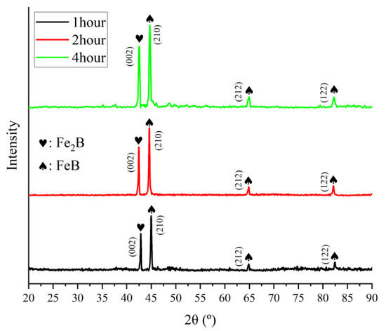
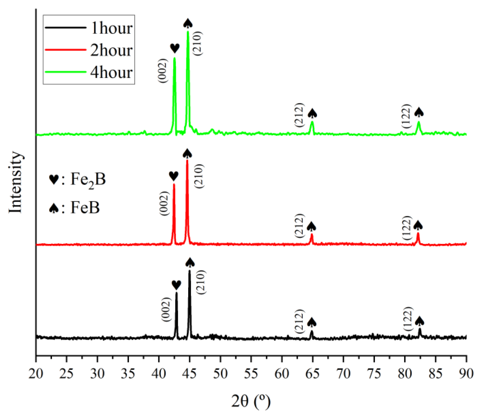
Figure 1 shows the XRD analysis result of borided samples surface with different boriding times. It is observed that the boride layer formed after 1 h, 2 h, and 4 h consists of a mixture of FeB and Fe2B phases. The characteristic diffraction peaks of the FeB phase correspond to the (210), (212), and (122) crystal planes, whereas those of the Fe2B phase correspond to the (002) crystal plane. In this mixed-phase system, the FeB (210) and Fe2B (002) peaks represent the dominant strong diffraction signals. With increasing boriding time, the intensity of the FeB (210) peak shows no significant variation, while that of the Fe2B (002) peak gradually increases. This trend suggests a possible rise in the relative content of the Fe2B phase as boriding time is extended. Consistent with the findings of Silveira et al., the formation of FeB as the outer layer and Fe2B as the inner layer is attributed to the high boron concentration gradient at the sample surface during vacuum boriding [33].
Figure 1.
The XRD analysis result of boriding sample surface with different boriding times.
3.2. Microstructure of Boride Layer
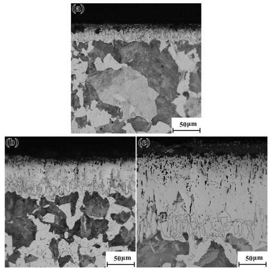
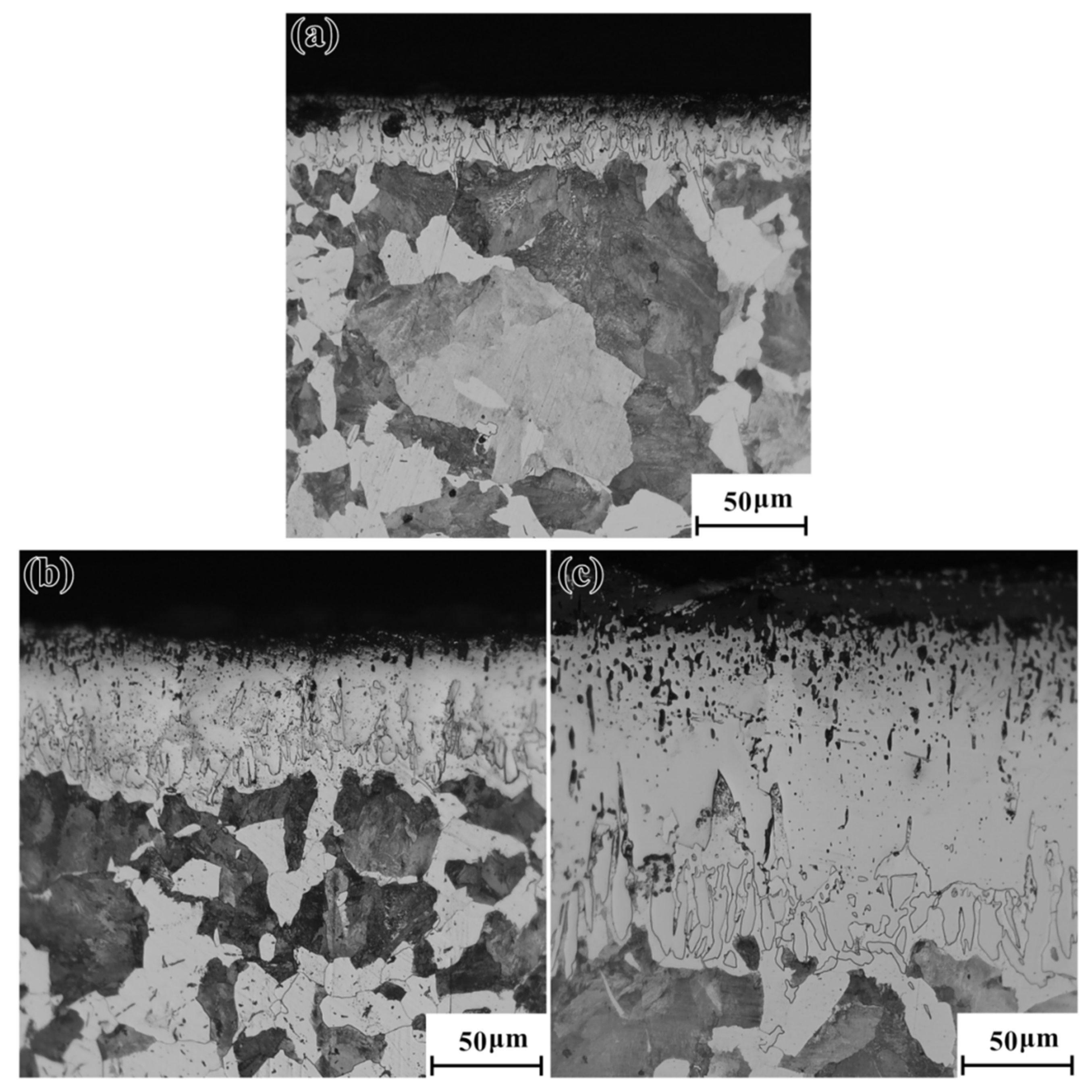
Figure 2 shows the microstructure of borided samples along the thickness direction with different boriding times. It was observed that a boride layer with a specific thickness was formed on the samples’ surface, exhibiting microstructural characteristics distinctly different from those of the core material. The thickness of the boride layer gradually increased with extended boriding time. When the boriding time was 1 h, 2 h, and 4 h, the corresponding boride layer thicknesses were approximately 40 μm, 70 μm, and 165 μm, respectively.
Figure 2.
The microstructure of boriding sample along the thickness direction with different boriding times: (a) 1 h, (b) 2 h, (c) 4 h.
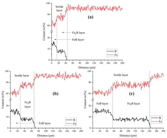
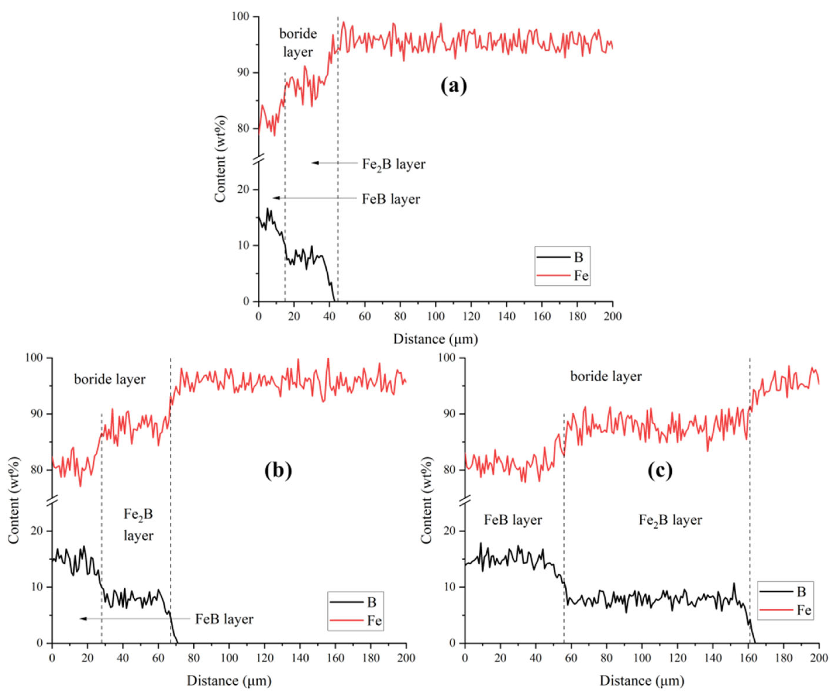
Figure 3 shows the element distribution of borided samples along the thickness direction with different boriding times. According to the existing literature, the mass fractions of boron in FeB and Fe2B phases are approximately 15% and 8%, respectively [34,35]. Based on the XRD phase analysis of the boride layer, it can be inferred that the boride layer consists of an FeB sublayer near the surface and an Fe2B sublayer beneath it. Both the total thickness of the boride layer and the thicknesses of its constituent sublayers increased with longer boriding times. For a boriding time of 1 h, 2 h, and 4 h, the total boride layer thickness was approximately 43 μm, 71 μm, and 164 μm, respectively, which aligned with the experimental results shown in Figure 2. Under the same conditions, the FeB sublayer thickness measured about 26 μm, 40 μm, and 109 μm, respectively, while the Fe2B sublayer thickness was approximately 17 μm, 31 μm, and 55 μm, respectively. The growth behavior observed in our study was consistent with the “diffusion enhancement effect” mechanism proposed by Cao et al. This diffusion enhancement effect not only increased the thickness of the boride layer but also optimized the phase composition [36].
Figure 3.
The element distribution of boriding sample along the thickness direction with different boriding times: (a) 1 h, (b) 2 h, (c) 4 h.
3.3. Hardness and Surface Topography
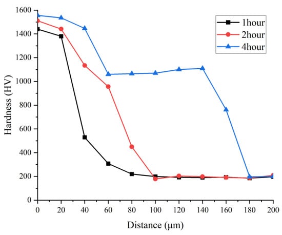
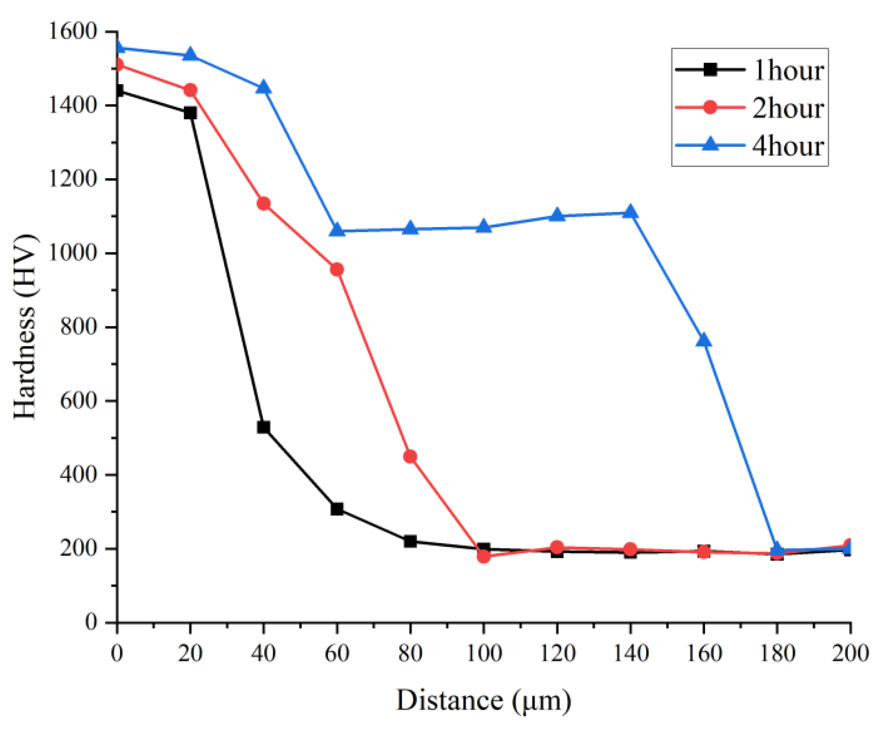
Figure 4 shows the hardness distribution of borided samples along the thickness direction with different boriding times. As shown in Figure 4, the distribution characteristics of the microhardness of the borided samples were characterized by a large degree of discreteness and a gradient distribution overall. The uniformity of the borided layer in the middle part of the sample that had been borided for 4 h had significantly improved. From the surface toward the interior along the thickness direction, the hardness gradually decreased and eventually approached the hardness level of the substrate. Based on the XRD analysis result shown in Figure 1 and element distribution analysis result shown in Figure 3, it is concluded that the variation in hardness is directly correlated with the phase structure of the boride layer. This correlation arises from the fact that both FeB and Fe2B phase are high hardness intermetallic compounds, whose hardness significantly exceeds that of the substrate material. Moreover, FeB (16 wt% B) has an orthorhombic structure and is composed of B-B covalent bonds, while Fe2B (8 wt% B) has a body-centered tetragonal structure [37]. Due to a higher degree of lattice distortion in the FeB phase compared with the Fe2B phase, the former possesses a greater hardness value. Measured average hardness values for the FeB layer, Fe2B layer, and substrate were approximately 1440 HV, 1050 HV, and 195 HV, respectively.
Figure 4.
The hardness distribution of boriding sample along the thickness direction with different boriding times.
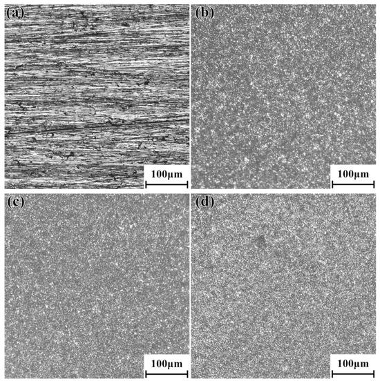
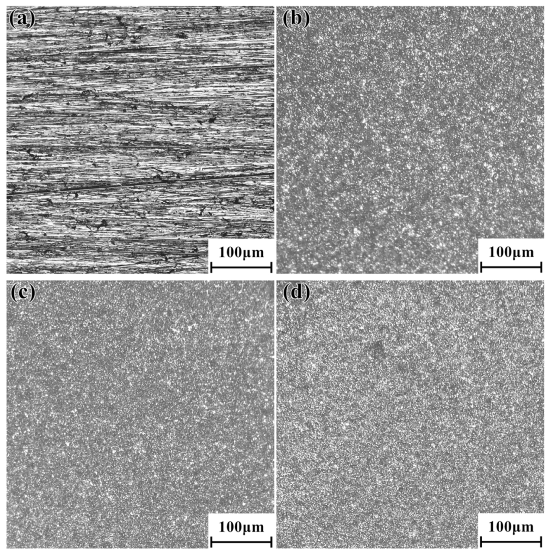
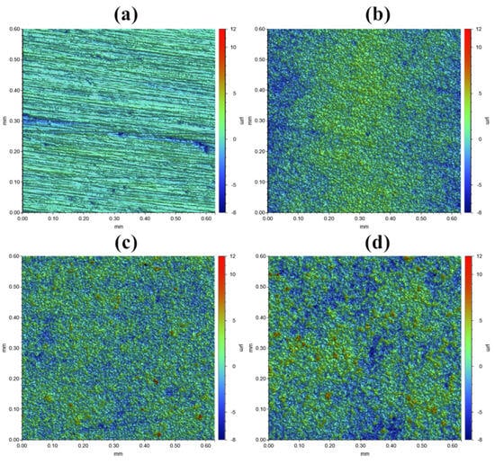
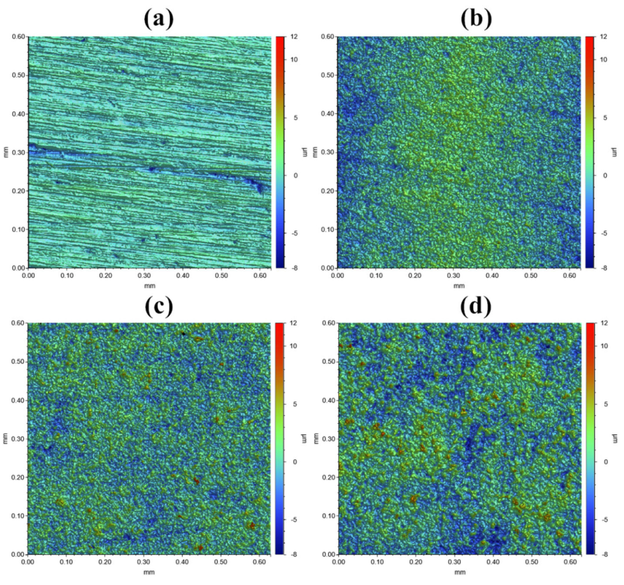
Figure 5 shows the surface topography of borided samples with different boriding times. Figure 6 shows the 3D profile of boriding samples with different boriding times. As shown in Figure 5a and Figure 6a, the untreated sample surface exhibits uniformly aligned linear scratches from sandpaper abrasion but no obvious protrusions, holes, or granular precipitates. However, the surface morphology of the borided sample evolves significantly, transitioning from linear scratches to a landscape of white protrusions. With increasing boriding time, the white protrusions grow in size and number.
Figure 5.
The surface topography of boriding sample with different boriding times: (a) untreated, (b) 1 h, (c) 2 h, (d) 4 h.
Figure 6.
The 3D profile of boriding sample with different boriding times: (a) untreated, (b) 1 h, (c) 2 h, (d) 4 h.
Table 2 shows the surface roughness of borided samples with different boriding times. The surface roughness (Sa) of samples increased as a function of boriding time, from 0.395 μm (untreated sample) to 1.186 μm, 1.711 μm, and 2.175 μm after 1 h, 2 h, and 4 h, respectively, indicating a substantial increase over the untreated sample. With the extension of boriding time, the St value exhibited an increasing trend, indicating that the extreme height difference between surface peaks and valleys gradually expanded, and the characteristics of extreme surface topography became more prominent. The Ssk values of all samples showed a trend of changing from negative to positive, but all values fell within the range of −0.1 to 0.2. This indicated that the distribution of peaks and valleys on the borided layer surface tended to be uniform overall, without obvious asymmetric topography dominated by either peaks or valleys.
Table 2.
The surface roughness of boriding sample with different boriding times.
During the diffusion process of boron atoms from the surface to the interior of the substrate, boride nodules formed on the sample surface. As the boriding time increased, the protrusions’ size grew, leading to an increase in roughness [38]. Given the use of a vacuum high-temperature boriding process in this study, the white protrusions on the sample surface should not be oxides. Moreover, according to the XRD analysis result shown in Figure 1 and element distribution analysis result shown in Figure 3, these white protrusions should be the boride FeB.
3.4. Corrosion Properties of Boride Layer
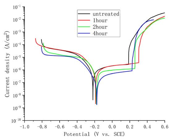
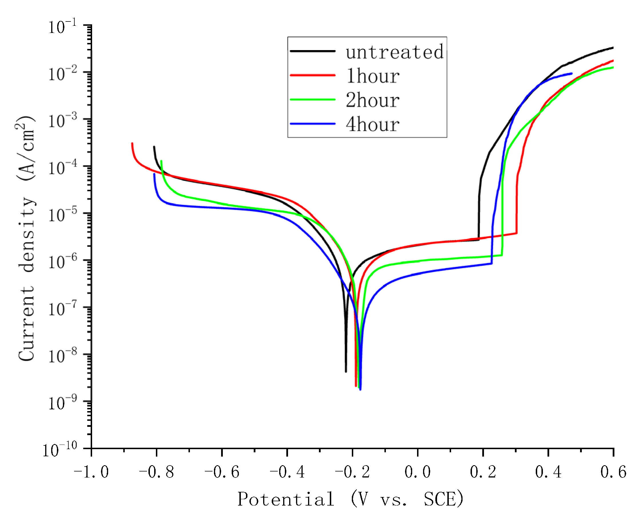
Figure 7 shows the polarization curve of borided samples with different boriding times. Table 3 shows the polarization curve fitting results of borided samples with different boriding times. When the boriding time was 0 h (i.e., the untreated sample), 1 h, 2 h, and 4 h, the corrosion potential (Ecorr) was about −0.221 V, −0.189 V, −0.181 V, and −0.175 V, respectively, showing an increase as the boriding time increased; and the corrosion current density (Icorr) was about 5.34 × 10⁻⁷ A/cm2, 3.98 × 10⁻⁷ A/cm2, 2.26 × 10⁻⁷ A/cm2, and 1.09 × 10⁻⁷ A/cm2, respectively, showing a decrease as the boriding time increased; the passivation current (ipass) was about 2.359 × 10⁻⁶ A/cm2, 2.561 × 10⁻⁶ A/cm2, 1.139 × 10⁻⁶ A/cm2, 6.844 × 10⁻⁷ A/cm2, respectively, showing a decrease as the boriding time increased. The improvement in corrosion resistance of the samples with increasing boriding time was indicated by the trend observed in the corrosion potential (Ecorr), corrosion current density (Icorr), and passivation current (ipass).
Figure 7.
The polarization curve of boriding sample with different boriding times.
Table 3.
The polarization curve fitting results of boriding sample with different boriding times.
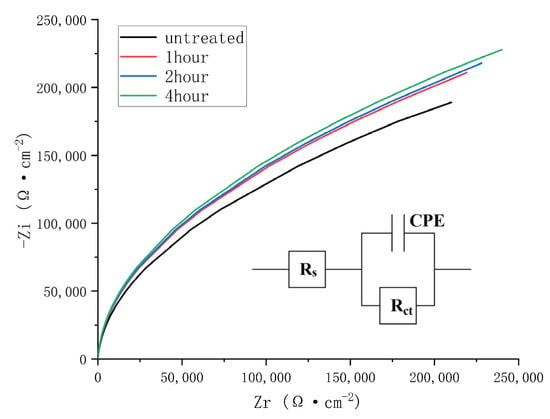
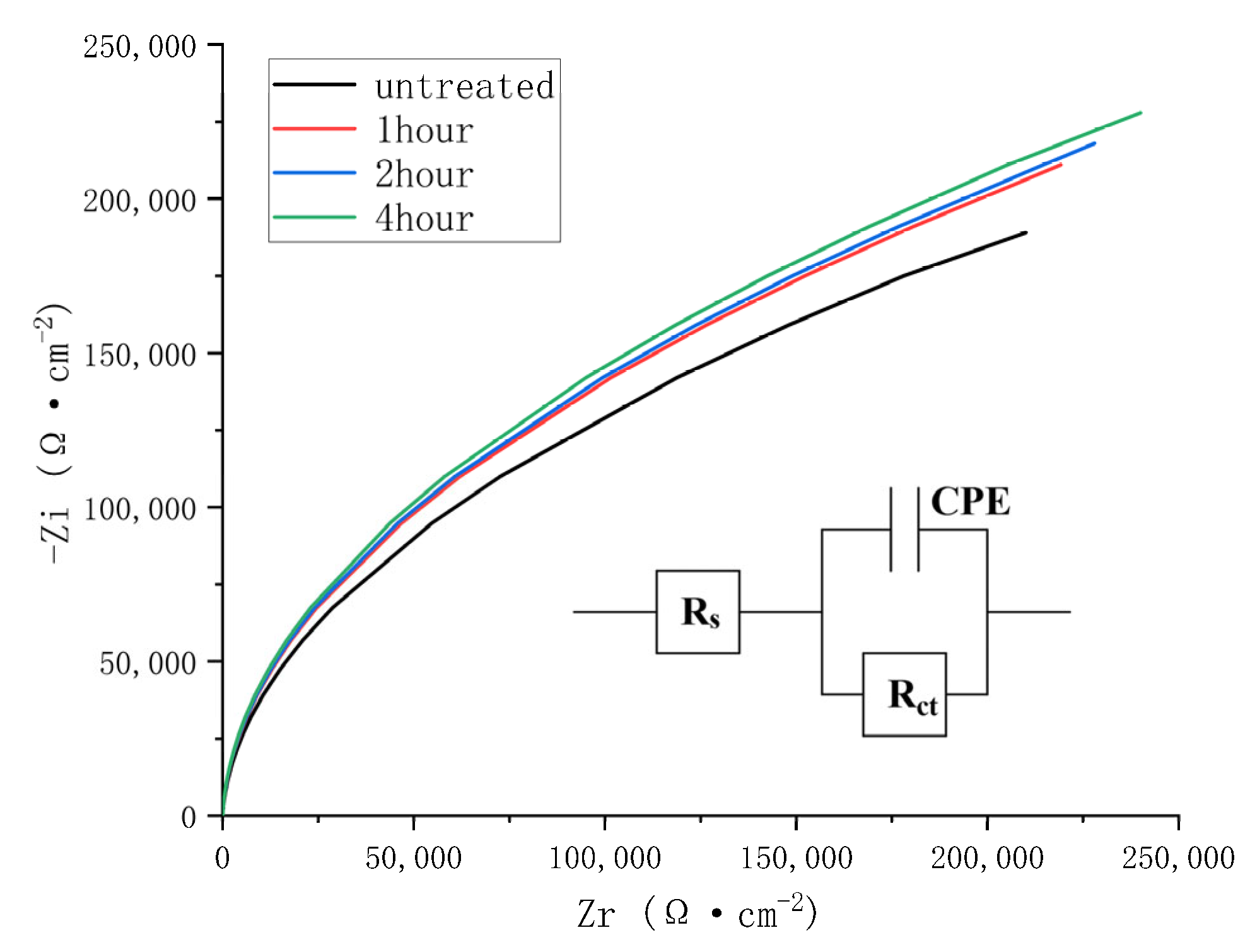
Figure 8 shows the Nyquist curve and its corresponding equivalent circuit of borided samples with different boriding times. As shown in Figure 8, essentially the same shape was exhibited by all Nyquist curves. Compared with the untreated sample, the radius of the Nyquist curves was significantly increased in the borided samples, and a gradual increase in radius was observed with longer boriding time. This indicates that the impedance of the samples was enhanced as the boriding time was extended. According to the EIS data, an equivalent electrical circuit of all samples was established, as shown in Figure 8.
Figure 8.
The Nyquist curve and its corresponding equivalent circuit of boriding sample with different boriding times.
Table 4 shows the fitting parameters of the equivalent circuit of borided samples with different boriding times. Rs and Rct are the electrolyte solution resistance and charge transfer resistance, respectively. CPE is the constant phase element, and n is the phase exponent that describes the degree of deviation from the ideal capacitance of CPE. The value difference of Rs, CPE, and n of all samples was not significant, which indicates that all samples have high consistency in their corresponding electrochemical characteristics. When the boriding time was 0 h (i.e., the untreated sample), 1 h, 2 h, and 4 h, the Rct was measured at approximately 3.461 × 10⁵ Ω·cm2, 4.207 × 10⁵ Ω·cm2, 4.289 × 10⁵ Ω·cm2, and 4.398 × 10⁵ Ω·cm2, respectively, showing an increase as the boriding time increased. Based on the trend in impedance and Rct values with increasing boriding time, the corrosion resistance of the samples was determined to be improved as the boriding time was extended.
Table 4.
The fitting parameter of equivalent circuit of boriding sample with different boriding times.
3.5. Comprehensive Correlation Analysis
During the solid boriding process, boron atoms released from the boron source diffused into the steel at a suitable temperature and reacted with iron atoms to form the Fe2B phase. With increased boriding time, the thickness of the Fe2B layer was also observed to increase. When sufficient boron atoms were available, extended boriding time enabled further diffusion of boron atoms into the steel, where they reacted with the surface Fe2B to produce the FeB phase. Simultaneously, boron atoms continued to react with iron atoms in the steel to form additional Fe2B. As a result, the thicknesses of both the Fe2B and FeB layers were increased. The reactions described above can be expressed by Equations (1) and (2) [39,40]:
The evolution of surface morphology and the increased roughness of borided samples can be attributed to the diffusion-controlled growth of boride phases and the associated volumetric expansion. During the formation of boride phases (i.e., FeB and Fe2B) in the boriding process, a significant lattice expansion was accompanied by the generation of borides, as their specific volume is larger than that of the ferritic or austenitic matrix. This volumetric mismatch induced localized surface uplift, thus transforming the initial uniform grinding scratches into a landscape of protrusions. As the boriding time increased, continuous boron atom diffusion and boride phase growth led to the coalescence and enlargement of these boride nodules, which was manifested as an increase in protrusion size and a higher density of the hard, white FeB protrusions visible in the micrographs. Consequently, the progressive development of this rugged, biphasic boride layer directly elevated the surface roughness. Moreover, the absence of oxides, ensured by the vacuum process, confirms that the morphological changes are intrinsically linked to the formation and growth kinetics of borides rather than surface oxidation.
The polarization curve test results are in good agreement with the electrochemical impedance spectroscopy (EIS) test results, and both the above two test results indicate the boriding treatment could improve the corrosion resistance of alloy steel, which is further improved with the increase in boriding time, can be ascribed to the formation and growth of a continuous and stable boride layer (FeB layer) on the steel surface. The FeB phase is thermodynamically stable and could act as an effective barrier that impedes the penetration of corrosive electrolytes. Moreover, as boriding time increases, the increase in the thickness and proportion of the FeB layer not only enhances the physical barrier effect but also reduces its anodic dissolution rate due to its high chemical stability, ultimately achieving effective suppression of overall corrosion.
In general corrosion scenarios for metallic materials, increased roughness amplifies the effective surface area and can trap corrosive electrolytes, thereby accelerating the degradation of the materials. However, in the case of boriding, the alloy steel surface is transformed from a reactive metallic state into a chemically inert ceramic-like layer composed of the FeB phase. The borides possess intrinsically high thermodynamic stability and low electrochemical activity in many corrosive environments. Although the growth of boride nodules increases macroscopic roughness, it creates a continuous, protective barrier that is fundamentally resistant to dissolution and ion penetration. When a sufficient and uniform boride layer is formed on the surface of the sample, the quality of the boride layer plays a dominant role in the corrosion resistance test compared to the surface roughness of the sample. The progressive thickening and densification of this boride layer with time, despite its topographical ruggedness, effectively isolate the underlying steel substrate from the corrosive medium. Consequently, the beneficial effect of the chemical passivity and microstructural continuity of the boride layer far outweighs the detrimental effect of the increased physical roughness.
4. Conclusions
Based on the systematic investigation of 18CrNiMo7-6 steel subjected to vacuum high-temperature solid boriding for different times, the principal findings are summarized as follows:
- A dual-phase boride layer, consisting of an outer FeB phase and an inner Fe2B phase, is successfully prepared on the steel surface. Both the total thickness of the boride layer and the individual thicknesses of the FeB and Fe2B sublayers are observed to increase significantly with prolonged boriding time.
- The boride layer exhibits a distinct gradient in hardness distribution, with the surface hardness reaching its maximum value. The average hardness of the FeB phase and the Fe2B phase was measured at approximately 1440 HV and 1050 HV, respectively, both of which are substantially higher than that of the substrate (approximately 195 HV).
- The surface roughness of the steel is significantly increased after boriding and is found to increase monotonically with longer boriding time. The roughness value Sa rose from 0.395 μm for the untreated sample to 2.175 μm after 4 h of boriding, which is primarily attributed to lattice expansion and the nodular growth of boride phases during the diffusion process.
- The corrosion resistance of the steel is remarkably improved after boriding and is further enhanced with extended boriding time. The corrosion current density of the sample treated with boron diffusion for 4 h was 1.09 × 10⁻⁷ A/cm2, which was approximately 79.6% lower than that of the base material. The continuous and dense dual-phase boride layer acts as an effective physical and chemical barrier that inhibits the penetration of corrosive electrolytes and reduces the electrochemical activity of the substrate, thereby outweighing the adverse effect of increased surface roughness on corrosion performance.
- When the boriding time was 4 h, the thickness of the FeB/Fe2B dual-layer borided layer reached the maximum, featuring both high hardness and excellent corrosion resistance. This indicates that 4 h is the optimal boriding process time for 18CrNiMo7-6 steel in a 1000 °C vacuum environment.
Author Contributions
Conceptualization: Y.L. and H.L.; methodology: Y.L. and H.L.; software: K.M.; formal analysis: K.M.; supervision: Y.L.; writing—original draft: K.M. and H.L.; writing—review and editing: Y.L., K.M., and H.L. All authors have read and agreed to the published version of the manuscript.
Funding
This work was supported by the Henan Provincial Science and Technology Research Project (No. 242102230006).
Institutional Review Board Statement
Not applicable.
Informed Consent Statement
Not applicable.
Data Availability Statement
Data is contained within the article.
Conflicts of Interest
The authors declare no conflicts of interest.
References
- Roa, C.V.; Valdes, J.A.; Larrahondo, F.; Rodríguez, S.A.; Coronado, J.J. Comparison of the resistance to cavitation erosion and slurry erosion of four kinds of surface modification on 13-4 Ca6NM hydro-machinery steel. J. Mater. Eng. Perform. 2021, 30, 7195–7212. [Google Scholar] [CrossRef] [Scilit]
- Cuao-Moreu, C.A.; Alvarez-Vera, M.; García-Sánchez, E.O.; Maldonado-Cortés, D.; Juárez-Hernández, A.; Hernandez-Rodriguez, M.A.L. Characterization of a duplex coating (boriding+ sputter-deposited AlCrON) synthesized on an ASTM F-75 cobalt alloy. Thin Solid Film. 2020, 712, 138318. [Google Scholar] [CrossRef] [Scilit]
- Qin, S.; Zhang, C.; Zhang, B.; Ma, H.; Zhao, M. Effect of carburizing process on high cycle fatigue behavior of 18CrNiMo7-6 steel. J. Mater. Res. Technol. 2022, 16, 1136–1149. [Google Scholar] [CrossRef] [Scilit]
- Guan, S.; Li, G.; Shi, Q.; Zuo, L.; Xiao, Y.; Zheng, H.; Peng, P. Process parameters optimization of plasma nitriding depth of 1Cr11Ni2W2MoV stainless steel: Experimental and simulation studies. JOM 2024, 76, 1937–1950. [Google Scholar] [CrossRef] [Scilit]
- Ayvaz, S.I.; Özer, E. Comparative study of conventional and microwave-assisted boriding of AISI 1040 and AISI 4140 steels. Teh. Glas. 2023, 17, 286–292. [Google Scholar] [CrossRef] [Scilit]
- Makuch, N.; Dziarski, P.; Kulka, M. Gas technique of simultaneous borocarburizing of armco iron using trimethyl borate. Coatings 2020, 10, 564. [Google Scholar] [CrossRef] [Scilit]
- Ivanov, Y.; Petrikova, E.; Shugurov, V.; Tolkachev, O.; Teresov, A. Formation of boron film on surface of austenitic steel in scheme of plasma-assisted rf-sputtering of cathode from boron. In Proceedings of the 2020 7th International Congress on Energy Fluxes and Radiation Effects (EFRE), Tomsk, Russia, 14–26 September 2020. [Google Scholar]
- Günen, A.; Lindner, T.; Karakaş, M.S.; Kanca, E.; Töberling, G.; Vogt, S.; Gök, M.S.; Lampke, T. Effect of the boriding environment on the wear response of laser-clad AlCoCrFeNi high entropy alloy coatings. Surf. Coat. Technol. 2022, 447, 128830. [Google Scholar] [CrossRef] [Scilit]
- Fu, Y.; Tong, W. Analysis of the boronizing process of high-vanadium alloy steel. J. Phys. Conf. Ser. 2023, 2553, 012015. [Google Scholar] [CrossRef] [Scilit]
- Jopek, J.; Góral, M.; Koscielniak, B.; Ochal, K.; Drajewicz, M.; Mokrzycka, M.; Kubaszek, T.; Dychton, K.; Gancarczyk, K.; Gradzik, A.; et al. The Influence of Industrial-Scale Pack-Boroding Process Time on Thickness and Phase Composition of Selected Cold-Work Tool Steels. Manuf. Technol. 2023, 23, 630–637. [Google Scholar] [CrossRef] [Scilit]
- Ma, L.S.; Duan, Y.H.; Li, P. Microstructure, growth kinetics and some mechanical properties of boride layers produced on pure titanium by molten-salt boriding. J. Mater. Eng. Perform. 2017, 26, 4544–4555. [Google Scholar] [CrossRef] [Scilit]
- Olivares-Luna, M.; Rosales-Lopez, J.L.; Castillo-Vela, L.E.; Chaparro-Pérez, K.D.; Delgado-Brito, A.M.; Mejía-Caballero, I.; Campos-Silva, I. Insights on the pulsed-DC powder-pack boriding process: The role of the electric charge on the growth of the boride layer and the semiconductor behavior of the boriding media. Surf. Coat. Technol. 2024, 480, 130588. [Google Scholar] [CrossRef] [Scilit]
- López-Leyva, A.; Rosales-Lopez, J.L.; Šulhánek, P.; Olivares-Luna, M.; Mejía-Caballero, I.; Gogola, P.; Campos-Silva, I. The impact of post-treatments on the brittleness and wear resistance of borided 8% Cr steel. Mater. Chem. Phys. 2024, 313, 128719. [Google Scholar] [CrossRef] [Scilit]
- Ocak-Araz, S.; Birden, A.; Bayca, S.U.; Bican, O. Effect of powder-pack boronizing on the microhardness, wear, and corrosion behaviors of AISI 304L steel. J. Mater. Eng. Perform. 2024, 33, 166–172. [Google Scholar] [CrossRef] [Scilit]
- Milinović, A.; Marušić, V.; Konjatić, P.; Berić, N. Effect of carbon content and boronizing parameters on growth kinetics of boride layers obtained on carbon steels. Materials 2022, 15, 1858. [Google Scholar] [CrossRef] [Scilit]
- Juijerm, P.; Angkurarach, L.; Naemchanthara, P. Direct current field enhanced boronizing of stainless steels and predictive performance of diffusion kinetics, deep neural network, and adaptive neuro-fuzzy inference system on boride layer thickness. J. Mater. Sci. 2023, 58, 16507–16522. [Google Scholar] [CrossRef] [Scilit]
- Liu, G.; Li, M.; Yang, L.; Liu, C.; Zhang, Y. Reactive molecular dynamics simulations of the initial oxidation and passivation of Fe-Cr alloy steel. Case Stud. Constr. Mater. 2024, 21, e03420. [Google Scholar] [CrossRef] [Scilit]
- Garip, Y. Improving the oxidation behavior of CoCrFe2Ni0.5 high entropy alloy through powder-pack boriding. High Temp. Corros. Mater. 2024, 101, 549–571. [Google Scholar] [CrossRef] [Scilit]
- Feng, Y.Y.; Yu, H.; Luo, Z.A.; Xie, G.M.; Misra, R.D.K. The impact of surface treatment and degree of vacuum on the interface and mechanical properties of stainless steel clad plate. Materials 2018, 11, 1489. [Google Scholar] [CrossRef] [Scilit]
- He, P.; Zheng, Y.; Li, J.; Qian, Y.; Lou, H.; Zhang, W. Analysis on mechanism of removing oxide film on stainless steel by heating in low vacuum. Trans. China Weld. Inst. 2012, 8, 93–96. [Google Scholar]
- Zhang, H.F.; Zhang, C.H.; Wang, Z.Y.; Cui, X.; Zhang, S.; Chen, H.T. Microstructure and corrosion behaviour of WC/NiCrBSi coatings by vacuum cladding. Mater. Sci. Technol. 2022, 38, 19–29. [Google Scholar] [CrossRef] [Scilit]
- Mertgenç, E.; Kayalı, Y.; Yalçın, M.C.; Yavuz, H. Effect of boron coating on rockwell-C adhesion and corrosion resistance of high entropy alloys. J. Mater. Eng. Perform. 2024, 33, 1194–1201. [Google Scholar] [CrossRef] [Scilit]
- Ortiz-Domínguez, M.; Gómez-Vargas, O.A.; Bárcenas-Castañeda, M.; Castellanos-Escamilla, V.A. Comparison and analysis of diffusion models: Growth kinetics of diiron boride layers on ASTM A283 steel. Materials 2022, 15, 8420. [Google Scholar] [CrossRef] [Scilit] [PubMed]
- Shi, M.; Li, J.; Mao, W.; Li, S.; Yang, Z.; Ma, X. Improving the wear and corrosion resistance of martensitic stainless steel by paste boriding treatment. Mater. Sci. Technol. 2023, 39, 300–309. [Google Scholar] [CrossRef] [Scilit]
- Dan, L.I.U. Corrosion and wear properties of TB2 titanium alloy borided by pack boriding with La2O3. Trans. Nonferrous Met. Soc. China 2022, 32, 868–881. [Google Scholar] [CrossRef] [Scilit]
- Terek, P.; Kovačević, L.; Terek, V.; Bobić, Z.; Miletić, A.; Škorić, B.; Drnovšek, A. Surface roughness and its effect on adhesion and tribological performance of magnetron sputtered nitride coatings. Coatings 2024, 14, 1010. [Google Scholar] [CrossRef] [Scilit]
- Luo, K.; Xing, Y.; Sun, M.; Xu, L.; Xu, S.; Wang, C.; Lu, J. Effect of laser shock peening on the dissolution of precipitates and pitting corrosion of AA6061-T6 with different original surface roughness. Corros. Sci. 2024, 228, 111794. [Google Scholar] [CrossRef] [Scilit]
- Zhu, T.; Nie, C.; Zhao, C.; Ying, L.; Wang, G.; Wu, W.; Zheng, T.; Lu, Y. Influence of elements in steel with anode plasma electrolytic boriding on hardness gradient and tribological properties. J. Tribol. 2024, 146, 121701. [Google Scholar] [CrossRef] [Scilit]
- Krelling, A.P.; Jeronimo, J.L.; Bonetti, I.; Souza, G.A.; Zappelino, B.F.; Pacheco, C.; da Costa, C.E. Influence of boriding on hardness and corrosion behavior in saline environment of Monel 400 nickel alloy. Mater. Lett. 2025, 385, 138159. [Google Scholar] [CrossRef] [Scilit]
- Wang, G.; Sang, X.; Wang, S.; Zhang, Y.; Xu, G.; Zhao, M.; Peng, Z. Surface integrity and corrosion resistance of 18CrNiMo7-6 gear steel subjected to combined carburized treatment and wet shot peening. Surf. Coat. Technol. 2024, 484, 130862. [Google Scholar] [CrossRef] [Scilit]
- Zhang, Y.; Quan, Z.; Lygdenov, B.; Guriev, A.M.; Mei, S. Research on the technology of paste boronizing for H13 die steel. IOP Conf. Ser. Mater. Sci. Eng. 2019, 684, 012007. [Google Scholar]
- Keddam, M.; Ortiz-Domínguez, M.; Elias-Espinosa, M.; Damián-Mejía, O.; Arenas-Flores, A.; Gómez-Vargas, O.A.; Zuno-Silva, J. Growth kinetics of the Fe2B coating on AISI H13 steel. Trans. Indian Inst. Met. 2015, 68, 433–442. [Google Scholar] [CrossRef] [Scilit]
- Silveira, L.L.; Pukasiewicz, A.G.M.; de Souza, G.B.; Soares, P.; Vidal, I.D.F.S.; Abrahão, R., Jr.; Torres, R.D. Microstructure design of powder-pack borided AISI 4140 steel. J. Mater. Eng. Perform. 2024, 33, 864–878. [Google Scholar] [CrossRef] [Scilit]
- Günen, A.; Bölükbaşı, Ö.S.; Özgürlük, Y.; Özkan, D.; Odabaş, O.; Somunkıran, İ. Effect of Cr addition on properties and tribological behavior at elevated temperature of boride layers grown on borosintered powder metallurgy alloys. Met. Mater. Int. 2023, 29, 748–766. [Google Scholar] [CrossRef] [Scilit]
- Ocampo-Ramírez, A.; Ballesteros-Arguello, A.; Melo-Pérez, M.A.; Rodríguez-Castro, G.A.; Nava-Leana, F.; Meneses-Amador, A. Fracture toughness of borided AISI 1045 steel with a diffusion annealing process. Surf. Coat. Technol. 2025, 497, 131754. [Google Scholar] [CrossRef] [Scilit]
- Cao, C.; Chen, D.; Chen, Z.; Song, X. Effect of Vacuum Diffusion on the Microstructure and Properties of Boron Permeability Layer of Austenitic Gray Cast Iron. Chin. J. Vac. Sci. Technol. 2024, 44, 436–444. [Google Scholar]
- Ortiz-Domínguez, M.; Morales-Robles, Á.J.; Gómez-Vargas, O.A.; de Jesús Cruz-Victoria, T. Analysis of Diffusion Coefficients of Iron Monoboride and Diiron Boride Coating Formed on the Surface of AISI 420 Steel by Two Different Models: Experiments and Modelling. Materials 2023, 16, 4801. [Google Scholar] [CrossRef] [Scilit]
- Jurči, P.; Hudáková, M. Diffusion boronizing of H11 hot work tool steel. J. Mater. Eng. Perform. 2011, 20, 1180–1187. [Google Scholar] [CrossRef] [Scilit]
- Li, X.; Liu, W.; Yuan, J.; Yuan, J.; Zhou, X.; Pan, T.; Ren, Y. The Influence of an Alternating Current Field on Pack Boriding for Medium Carbon Steel at Moderate Temperature. Coatings 2025, 15, 39. [Google Scholar] [CrossRef] [Scilit]
- Keddam, M.; Jurči, P. Simulating the growth of dual-phase boride layer on AISI M2 steel by two kinetic approaches. Coatings 2021, 11, 433. [Google Scholar] [CrossRef] [Scilit]

Disclaimer/Publisher’s Note: The statements, opinions and data contained in all publications are solely those of the individual author(s) and contributor(s) and not of MDPI and/or the editor(s). MDPI and/or the editor(s) disclaim responsibility for any injury to people or property resulting from any ideas, methods, instructions or products referred to in the content. |
© 2026 by the authors. Licensee MDPI, Basel, Switzerland. This article is an open access article distributed under the terms and conditions of the Creative Commons Attribution (CC BY) license.