


Abstract
To enhance drive performance, this paper introduces an advanced speed controller architecture intended for a brushless DC motor (BLDCM) operating under field-oriented control (FOC). This newly developed controller integrates decision tree theory (DTT) with sliding mode theory (SMT). Initially, the regression algorithm from the classification and regression tree (CART) framework is applied to partition the deviation between the actual motor speed and the target command into 10 distinct error zones. These intervals serve as the basis for configuring three critical parameters of a standard exponential reaching law sliding mode controller (ERLSMC): namely, the sliding mode dynamic trajectory control gain, the exponential reaching gain, and the constant speed reaching gain. Following each split, the mean squared error (MSE) of the respective nodes is evaluated to determine the root node. The dataset is recursively bifurcated into dual subsets using the chosen split variables and thresholds, establishing a structured decision pathway through each successive child node. As a result, the sliding mode speed controller receives dynamically optimized modifications for its three key gains in real time during BLDCM operation. In addition, the controller continuously computes an updated sliding mode dynamic trajectory control gain by tracking the derivative of the speed error. Tuning these three operational gains effectively mitigates the transient overshoot typically induced by the conventional exponential reaching law (ERL) across diverse running states. This mechanism ensures that the speed response of the BLDCM drive system dynamically and accurately follows target commands under fluctuating conditions. Advantageously, the introduced control strategy avoids intensive computational routines and eliminates the need for extensive training datasets, ensuring straightforward implementation. To validate this approach, the proposed methodology is applied to the BLDCM drive system using the Matlab/Simulink environment. Its execution is benchmarked against conventional sliding mode controllers (SMCs) configured with three distinct control strategies: the constant speed reaching law (CSRL), the standard ERL, and the extension theory combined with exponential reaching law (ETERL). The resulting simulation data confirms that the proposed adaptive controller delivers superior performance over the alternative three reaching laws regarding both transient command tracking and robustness in load regulation.
1. Introduction
In recent years, due to the rapid development of technology, the requirements for motor drive performance have increasingly risen; therefore, AC motors have also received significant attention. Among permanent magnet synchronous motors [1], the brushless DC motor (BLDCM) [2] has become a preferred choice in industrial applications because of its notable advantages, including high torque output, excellent torque-to-weight ratio, superior efficiency, and low acoustic noise. As demands for faster speed response and higher precision in position control continue to rise, field-oriented control (FOC) [3] has been extensively adopted in industry to achieve accurate speed and position regulation.
Conventional FOC establishes closed-loop control through coordinate transformations and three proportional-integral (P-I) controllers [4], namely the speed controller, the d-axis controller, and the q-axis controller. Despite the simplicity of P-I controller design, it struggles to balance command tracking with load regulation and its effectiveness diminishes under external disturbances. Moreover, different control strategies each present inherent limitations. For example, although the classical sliding mode controller (SMC) [5] demonstrates strong robustness against interference, it still fails to simultaneously ensure both command tracking accuracy and satisfactory load regulation. SMC features three core aspects: (1) Robustness against parameter uncertainties and external disturbances; (2) Finite-time convergence to the sliding surface; and (3) The chattering phenomenon induced by high-frequency switching, which this paper aims to mitigate. Recently, advanced SMC variants for BLDCMs—such as adaptive SMC (ASMC) [6], terminal SMC (TSMC) [7], and super-twisting SMC [8]—have been proposed to enhance control performance. However, they often heavily rely on complex disturbance or uncertainty estimators to compensate for lumped uncertainties [9]. Unlike these methods, the proposed DTTSMC achieves excellent disturbance rejection and robustness relying solely on the real-time classification of the speed error. This core advantage eliminates the need for extra state estimator architectures, thereby significantly reducing the digital computational burden. Fuzzy logic theory (FLT) is applicable to various fields due to its ease of design and strong robustness against disturbances; however, it suffers from overly lengthy computation times. Moreover, because it solves problems through approximation, its performance may be insufficient for systems requiring high control precision, such as highly nonlinear systems or those needing fast dynamic responses. As for extension theory (ET) [10], although it can flexibly adjust system parameters to meet different dynamic performance control requirements, there are concerns about system instability if operating points fall outside the neighborhood domain. The two-degree-of-freedom controller (2DOFC) enhances overall control performance by combining a feedforward controller and a P-I controller; due to its design that separates target tracking and disturbance rejection, it features high flexibility and is suitable for complex control demands. Nevertheless, the parameters of this controller are difficult to design and tune, which is not only time-consuming but also inefficient. While decision tree theory (DTT) involves simple calculations, it is more suitable for linear problems such as classification and regression. DTT has a rich developmental background in machine learning. Among the primary decision tree algorithms, CHAID typically relies on chi-squared tests for multiway splits, whereas CART utilizes criteria like the Gini index or mean squared error for binary recursive partitioning, making it highly effective for numerical optimization. In addition to basic decision trees, ensemble learning methods—such as Random Forest and Gradient Boosting Trees—have also seen increasing applications in control systems. However, for more complex nonlinear problems, it is prone to producing erroneous results due to data perturbations or uncertainties. Therefore, it is necessary to introduce algorithms into the controller or combine different control laws to achieve adaptive capabilities [11] and further enhance control performance. Examples include combining FLT with a P-I controller [12], combining ET with an SMC [13], and combining extendable fuzzy theory (EFT) with a 2DOFC [14]. However, integrating FLT with a conventional P-I controller cannot fully deliver the expected control performance in terms of both speed command tracking and load regulation responses. A scheme that combines ET with a SMC tends to produce slight overshoot when the speed command undergoes minor increases, while EFT together with a 2DOFC still results in small oscillations during the recovery phase of load regulation. To overcome these limitations, this paper introduces a control approach that integrates DTT with sliding mode theory (SMT). By adaptively adjusting three variable parameters of the SMC under different operating conditions within the rated speed range, the proposed method enhances system stability and achieves robust adaptive control performance.
The control law designed in this study employs the speed error—defined as the difference between the commanded and actual motor speed—as the key feature. Using the classification and regression tree (CART) algorithm within the DTT framework, this error signal is divided into ten intervals. Based on these partitions, the parameters for the sliding mode dynamic trajectory gain, the exponential reaching gain, and the constant speed reaching gain of the exponential reaching law-based SMC are configured. The optimal splitting threshold is calculated to establish the root node, and recursive partitioning is applied to construct the complete decision tree. During BLDCM operation, the controller outputs appropriate real-time adjustments for the three gains, while a new dynamic trajectory gain is recalculated according to the rate of change of the speed error. This mechanism effectively mitigates the overshoot observed when only the exponential reaching law is applied, thereby improving performance across diverse operating conditions. Finally, simulation results are presented to validate and compare the proposed controller against three other sliding mode controllers (SMCs) employing different reaching laws, with respect to speed tracking accuracy and load regulation responses.
The remainder of this paper is organized as follows: Section 2 introduces the field-oriented control (FOC) architecture and mathematical model of the BLDCM drive system; Section 3 details the proposed improved control algorithm combining DTT and SMT; Section 4 presents the Matlab/Simulink (2024b version) simulation verification results and compares them with three other controllers; and finally, a conclusion is made in Section 5.
2. Brushless DC Motor Drive System
The primary difference between a BLDCM and a brushed DC motor (BDCM) lies in the commutation method. A BDCM relies on the mechanical contact between brushes and a commutator for commutation; as the rotor turns, the brushes continuously switch contact points, altering the current direction to generate a continuously rotating magnetic field. In contrast, a BLDCM employs an electronic commutation method. By integrating magnetic components such as Hall effect sensors or optical encoders [15] onto the rotor shaft, it detects and feeds back the rotor’s position to the controller in real-time. By detecting the rotor’s position, the controller modifies the orientation of the stator currents. This action sustains a rotating magnetic field, enabling the rotor to be driven smoothly and ensuring proper commutation.
2.1. FOC Architecture of the BLDCM System
FOC alternatively designated as vector control, leverages coordinate transformation matrices [16] to project the three-phase alternating voltage and flux relations of the BLDCM onto a synchronous two-axis reference frame. This mathematical conversion substantially simplifies the underlying plant model [17], thereby alleviating digital processing demands while shrinking the overall complexity of the controller design. Mechanistically, the control sequence utilizes internal P-I regulators to decouple current feedback signals into voltage channels prior to executing the coordinate variations. Following this, space vector pulse width modulation (SVPWM) is deployed to govern the switching states of the six power semiconductor devices housed inside the main inverter bridge [18]. Dynamic variables—specifically the motor’s rotational velocity, operating voltage, and phase currents—are continuously collected and returned to the closed-loop system, enabling the primary speed controller to accurately follow target velocity commands while driving steady-state deviations to zero.
Within this synchronous rotating d-q coordinate framework, assuming a surface-mounted permanent magnet BLDCM configuration devoid of damper windings allows the rotor’s permanent magnets to be mathematically modeled as an equivalent constant current source. By aligning the angular velocity of an arbitrary rotating reference frame directly with the electrical speed of the rotor, the operational constraint can be successfully established as . Furthermore, the electrical rotor speed of a synchronous motor coincides with its synchronous speed, giving . The rotor current, which produces the magnetic field, is denoted as . Since the rotor’s permanent magnets are located solely along the d-axis, they can be modeled as a constant current source on that axis, while the q-axis current remains zero. Accordingly, the magnetic flux relations are described in Equations (1) and (2).
where and represent the flux linkages of the stator d-axis and q-axis, respectively. The flux linkage produced by the permanent magnets in the stator windings is given as . Accordingly, the stator voltages are formulated in Equations (3) and (4).
where and correspond to the voltages along the d-axis and q-axis of the stator, represents the stator resistance, and correspond to the stator currents of the d-axis and q-axis, indicates the electrical angular velocity, and and denote the stator inductances of the d-axis and q-axis. Because the d-axis faces the stator windings directly while the q-axis faces the stator core, the reluctance of the d-axis is greater, hence .
The relationships describing electromagnetic torque and mechanical behavior of the motor are given in Equations (5) and (6).
where is the electromagnetic torque, is the number of poles, is the moment of inertia, is the mechanical rotational speed, and is the load torque.
If FOC is adopted, we can set , which also simplifies Equations (3)–(5) to Equations (7)–(9).
From the correlation between and the q-axis current given in Equation (9), the torque constant can be expressed as Equation (10).
Substituting Equation (10) into the BLDCM mechanical motion equation yields the rearranged form shown in Equation (11).
Within the FOC framework, coordinate transformations serve to reduce equation complexity while transforming time-dependent variables into steady values. To achieve this, the d-axis of the two-axis stationary frame is aligned with the q-axis of the three-phase stationary frame. Subsequently, the Clarke transformation is applied to map the motor’s feedback three-phase currents into their two-phase stationary counterparts, as illustrated in Equation (12).
Then, the Park transformation is used to convert the stationary coordinate AC currents into synchronous coordinate DC currents, which are fed back into the controller; this transformation expression is shown as Equation (13).
The inverse Park transformation can convert the voltages in the -axis synchronous rotating frame coordinates into AC voltages in the stationary frame coordinates, as shown in Equation (14).
Subsequently, the voltages and generated through this transformation are used for SVPWM. Then, through its internal inverse Clarke transformation, the two-phase AC voltages are converted into three-phase AC voltages, thereby controlling the switching of the inverter; its transformation equation is shown as Equation (15).
By following the preceding steps, the BLDCM system achieves closed-loop regulation. Analysis of the torque and voltage equations shows that under FOC, the q-axis current directly governs torque output, while the d-axis voltage depends solely on the q-axis current. This confirms that, within the BLDCM architecture, the method streamlines the control process and reduces its complexity.
2.2. P-I Controller
A P-I controller is widely applied in control systems to regulate stability and response speed, favored for its simple structure and ease of parameter tuning. Within the FOC framework of a BLDCM, P-I controllers are generally employed to manage closed-loop regulation of both speed and current. For current regulation in the d and q-axes, the three-phase currents are transformed into the stator components and . Each axis is then controlled independently by its respective P-I regulator to achieve accurate magnetic field orientation and torque production. To maximize torque output—namely, to realize maximum torque per ampere (MTPA) [19]—the condition is imposed. The q-axis P-I controller subsequently adjusts its input according to the error between the measured current and the reference , thereby ensuring precise torque regulation. The reference itself is generated by the speed-loop P-I controller, based on the deviation between the commanded and actual motor speed. In this manner, the three P-I controllers collectively guarantee that the motor output satisfies control objectives, enabling fast dynamic response and elimination of steady-state error.
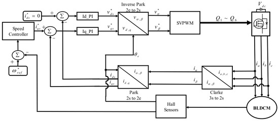
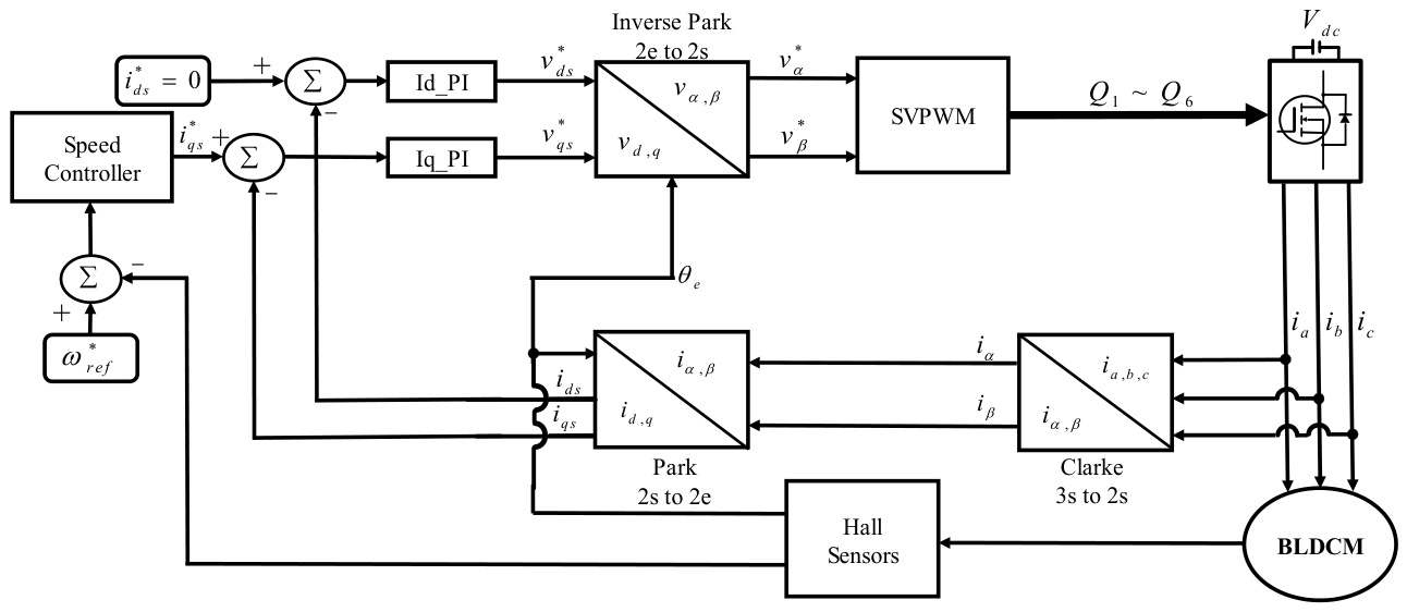
Although P-I controllers are effective in many applications, their precision may degrade in nonlinear systems, and their responsiveness can be limited under rapid dynamic variations. Therefore, this study replaces the speed-loop P-I controller with an improved design, aiming to optimize both speed command tracking and load regulation performance. Figure 1 shows the block diagram of the FOC for the BLDCM.
Figure 1.
Block diagram of the FOC for the BLDCM.
3. Improved Algorithm Based on Decision Tree Theory
When the speed loop in FOC relies solely on a P-I controller, it becomes challenging to achieve both accurate speed command tracking and effective load regulation. To address this limitation, the paper introduces an enhanced controller to replace the conventional P-I design. This controller integrates DTT with Sliding Mode Theory (SMT); by applying DTT, the parameters of the Sliding Mode Controller are dynamically assigned within predefined error ranges according to the deviation between the actual rotational speed and the desired command. In this way, adjustable robust control [20] is realized, leading to improved overall performance.
3.1. Decision Tree Theory
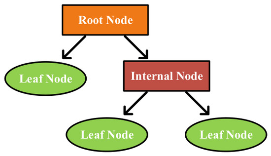
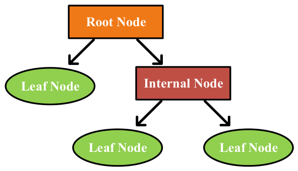
Decision tree is a classical machine learning and data mining method. Its core idea is to decompose the decision-making process through a tree-like structure, which is used to solve classification and regression problems. Its basic structure is divided into three parts: the root node (also known as the parent node), internal nodes (also known as split nodes), and leaf nodes (also known as child nodes). Among them, the root node is the starting point of the decision tree, each internal node represents a decision or split, and the leaf node is the endpoint of the decision tree, representing the final classification result or regression value. Figure 2 shows the architecture diagram of a decision tree.
Figure 2.
Decision tree architecture diagram. Orange indicates the root node, red indicates internal nodes, and green indicates leaf nodes. Arrows denote parent–child relationships.
The development of DTT primarily originates from the fields of statistics and artificial intelligence, with its history tracing back to the 1960s. Over time, it has evolved into algorithms suitable for various problems, such as ID3 (iterative dichotomiser 3), C4.5, CHAID (chi-squared automatic interaction detector), and CART (classification and regression trees) [21]. Among them, the ID3 algorithm uses entropy and information gain as splitting criteria and is only applicable to classification problems. C4.5 is an improved version of ID3; because it can handle continuous features, it is superior to the former. The CHAID algorithm splits based on chi-squared tests and is commonly used in marketing and behavioral analysis. The CART algorithm introduces the Gini index and mean squared error (MSE) or mean absolute error (MAE) as splitting criteria for classification trees and regression trees, respectively, making it a relatively common decision tree algorithm today.
3.1.1. Classification and Regression Trees Algorithm
The CART algorithm was proposed by Leo Breiman et al. in 1984 [21]. It systematically constructed the theory of decision trees through the CART model, encompassing algorithm frameworks for both classification and regression trees. By utilizing the Gini index and MSE or MAE as splitting criteria, it identifies the optimal splitting point (i.e., root node). Because it is applicable to both classification and regression problems, its scope of application is broader, making it a core foundation and a widely used method among modern decision tree algorithms.
In classification trees, CART uses the Gini index as the splitting criterion, as shown in Equation (16).
where is the proportion of the i-th category in node t, and is the number of categories.
The Gini gain, used to select the optimal splitting point, can be obtained from Equation (17).
where and are the left child node and right child node, respectively, is the number of samples in node t, and and are the number of samples in the left and right child nodes, respectively.
In regression trees, CART uses MSE or MAE as the splitting criterion, as shown in Equations (18) and (19), respectively.
where is the actual value of sample i, and is the sample mean in the node (i.e., the average predicted value), which can be expressed as Equation (20).
The and used to select the optimal splitting point are expressed as Equations (21) and (22), respectively.
where MAE is the mean absolute value of the error, so it is more tolerant of a small number of large errors, making it suitable for problems seeking stable predictions. MSE is the mean squared value of the error, thereby amplifying the impact of larger errors, so it can ensure the uniformity of data within each leaf node by minimizing the squared difference after splitting, making it suitable for situations where suppressing large errors is desired. Therefore, decision trees commonly use MSE as the splitting criterion in regression problems.
3.1.2. Pruning
The pruning technique of decision trees is a method for model optimization; its main purpose is to reduce overfitting and improve the model’s generalization ability. During the generation process of a decision tree, it is easy to generate a complex structure, making it perform well on training data but potentially overfit on unknown data. Therefore, pruning techniques are used to trim the decision tree after it is constructed to reduce unnecessary branches, thereby simplifying the model. The methods are mainly divided into pre-pruning and post-pruning [22]. Among them, pre-pruning stops the partitioning early during the tree building process; by setting limits to decide whether to continue branching, it stops expanding nodes when the branches cannot meet the conditions, preventing the tree from becoming overly complex. Post-pruning, on the other hand, first generates a complete decision tree, and then trims it from the bottom up, deleting branches that contribute less to the model. It commonly uses cross-validation or evaluates accuracy to confirm whether to prune, ensuring reduced error and enhanced generalization ability.
3.1.3. Generation Principle of Regression Trees
A decision tree essentially works by recursively dividing the sample space based on feature values, creating a tree structure where internal nodes signify features and branches represent their respective values. This splitting continues until each leaf node contains only one category or meets certain stopping criteria. The regression tree is specifically used for predicting continuous variables, so it is more suitable for motor speed control compared to the classification tree. Its main purpose is to partition the data space so that the relationship between the target variable (i.e., output) on each leaf node and the input variables can be best represented.
To address the specific control requirements, the CART regression tree’s interval split points are not manually assigned but derived through a systematic, data-driven procedure. During training, the input data comprises discrete dynamic characteristics of speed errors collected under various step commands using standard sliding mode control, with the objective of minimizing the dynamic mean squared error (MSE). Using MSE reduction as the splitting criterion, the CART algorithm automatically partitions the data into 10 highly homogeneous operating intervals, distinguishing this method from traditional manual trial-and-error approaches. For the corresponding gain values, safe numerical ranges are initially established via trial-and-error within classic sliding mode stability boundaries. The decision tree then precisely maps these optimized gains to each error interval, perfectly combining machine learning’s objective partitioning with control theory’s stability guarantees.
The general construction process of a regression tree under this algorithmic framework is explained as follows:
Step 1: Calculate the MSE reduction value for each feature and splitting point according to the splitting criterion, and select the splitting point corresponding to the maximum reduction value.
Step 2: Split the dataset into two parts based on the selected splitting point using a dichotomous method.
Step 3: Repeat the above steps for each child node until the stopping condition is met.
Step 4: To prevent overfitting, the generated regression tree can be pruned.
3.2. Sliding Mode Controller
While P-I controllers can achieve satisfactory performance under limited operating conditions, their control capacity weakens when the BLDCM system is influenced by nonlinear interactions, parameter fluctuations, load variations, or external disturbances. Hence, sliding mode control (SMC) is introduced in this work as a variable-structure control scheme [23] to enhance robustness. Recent investigations have demonstrated that coupling sliding mode theory with optimization-based strategies can further boost speed tracking accuracy and disturbance rejection [24]. For speed regulation, the goal is to reduce the discrepancy between the commanded speed and the measured motor speed . The state variables are therefore defined in Equation (23).
where and act as the functional formulations of the system state variables, which trace the speed tracking deviation alongside the corresponding error variation rate, respectively. Based on these state variables, the sliding mode dynamic trajectory is selected as Equation (24).
where is the sliding surface function and is the sliding surface control gain. When the system state reaches , the speed error converges toward zero along the designed sliding trajectory. Thus, the speed response can be regulated through the proper design of the sliding surface and reaching law.
To guarantee stability once the system state reaches the sliding surface, the introduction of a reaching law is necessary [25]. Here, the exponential reaching law is utilized and formulated in Equation (25).
where is the constant-speed reaching gain, is the exponential reaching gain, and is the sign function. Compared with the constant-speed reaching law, the exponential reaching law provides a faster convergence rate when the system state is far from the sliding surface, while reducing the reaching speed near the sliding surface to suppress chattering. According to Lyapunov stability theory [26], by selecting , the reaching law satisfies the stability requirement when .
By differentiating the sliding surface and substituting the simplified BLDCM mechanical equation, the relationship between the sliding surface derivative and the controller output can be written as Equation (26).
where is the q-axis reference current generated by the speed controller, and is the torque-related coefficient of the BLDCM model. Combining the above equation with the exponential reaching law, the q-axis reference current is obtained as Equation (27).
The generated is then sent to the inner current control loop to complete the speed-loop controller design. Through this structure, the proposed SMC reduces the dependence on fixed P-I gains and improves the robustness of the BLDCM drive system under speed command variation and load disturbance.
3.3. Feature Selection for the Motor Drive System Combining DTT and SMC
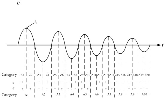
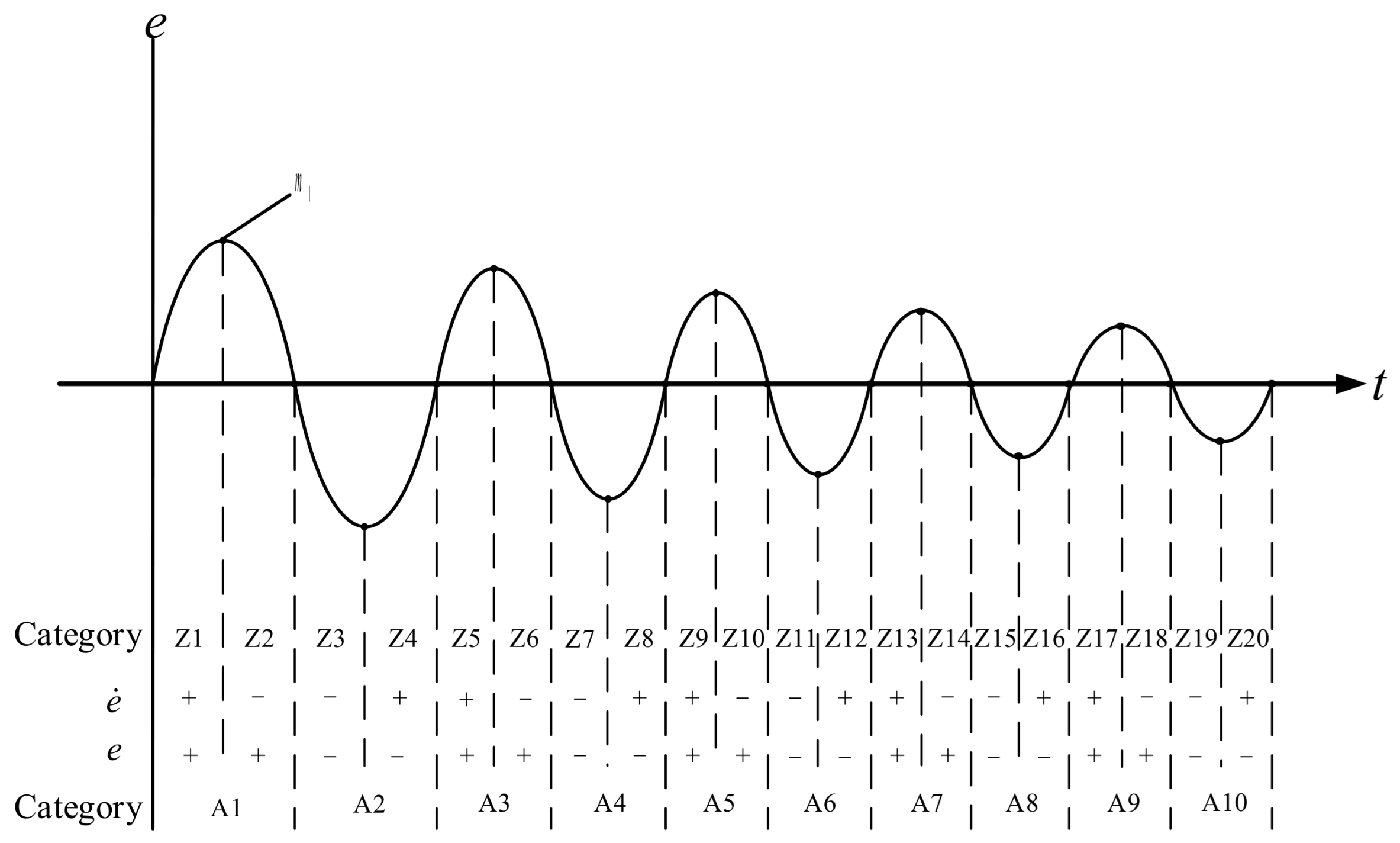
In order to enhance both speed and stability of the BLDCM control response, the error between the commanded and actual motor speed across its operating range is partitioned into 20 intervals (20 states). The correlation among these intervals is illustrated in Figure 3. As can be seen from Figure 3, intervals Z1~Z4 have larger amplitude oscillations due to the larger gap with the speed command, while intervals Z17~Z20 have smaller speed errors, thus the amplitude oscillations are smaller. Taking the Z1 interval as an example, and is increasing; although , its value is decreasing, and at point , , yet is at its maximum. For instance, in the Z1 interval, the error continues to increase, and the controller needs to output a higher control gain to cope with the larger error; as approaches steady state, its control output gradually weakens.
Figure 3.
Dynamic analysis diagram of speed error and rate of change of speed error for the brushless DC motor.
Crucially, transient information from the rate of change of the speed error is not omitted. In traditional sliding mode control, the sliding surface inherently combines and linearly, meaning dynamics are already embedded in the control law calculations. Redundantly including the highly time-coupled in the decision tree feature set would drastically increase dimensionality, microcontroller computational burden, and the risk of system overshoot. Therefore, using solely as the DTT input is an optimal trade-off, balancing computational simplicity with superior control performance. This simplified feature set effectively reduces the dynamic analysis shown in Figure 3 into 10 error-based intervals while still delivering highly stable transient and step-tracking responses. The control strategy for each interval corresponds to the three variable parameters in the SMC, including the sliding mode dynamic trajectory control gain , the exponential reaching gain , and the constant speed reaching gain . However, because the constant speed reaching gain is not only related to the speed response but also has a decisive correlation with stability, it differs from the feature intervals of the other two. By modulating these gain values to adjust the dynamic model and reaching law function of the SMC, the transient response of the system is made faster, while simultaneously effectively suppressing the overshoot caused by the ERL.
3.4. Speed Control Combining DTT and SMC
For achieving fast and stable speed regulation, this study employs the deviation between the reference speed and the actual motor speed as a feature for DTT-based MSE evaluation, while concurrently determining the dynamic trajectory function of the sliding mode controller. To clearly illustrate the data processing flow without an additional flowchart, the proposed algorithm is systematically structured into eight core steps. These steps detail the entire process: inputting the speed error, utilizing the CART algorithm to calculate the MSE for optimal split points, classifying the error intervals, dynamically adjusting the sliding mode trajectory and exponential reaching gains, and ultimately outputting the q-axis reference current . First, the DTT is used to find the highest MSE reduction value ∆MSE, and it is classified as the optimal splitting point to serve as the root node of the decision tree. Then, based on this, the appropriate feature category intervals are assigned, which in turn maps the pre-tuned three gain parameters for the SMC. The SMC adopts the ERL to enhance the response of the motor speed. Its control flow uses DTT to calculate the MSE, performs motor speed feature classification, and then allocates the three gain parameters in the sliding mode dynamic trajectory function and the ERL function that can stabilize the system, so as to suppress the overshoot brought by the ERLSMC. Taking the sliding mode dynamic trajectory control gain ∆MSE as an example, the process of determining the gain parameters by the DTT is detailed as follows:
Step 1: For the corresponding feature set and the corresponding target set of each feature, construct a mathematical model as shown in Equation (28).
where N is the number of samples in the value range of 1 to n, and is the number of features.
Step 2: From Equation (24), it is known that when calculating the sliding mode dynamic trajectory function , the SMC already has a regulating and correcting effect on the rate of change of the speed error. Therefore, the rate of change of the speed error is ignored, and only the speed error to be classified is inputted to establish the mathematical model:
Step 3: Calculate the average predicted value from Equation (20), and substitute the calculated result into Equation (18) to obtain the initial MSE value .
Step 4: Substitute the calculated average predicted value and initial MSE value into Equation (21) to calculate the MSE reduction value for each node, and regard the obtained maximum value as the optimal splitting point to serve as the root node of the decision tree.
Step 5: Based on the obtained root node, split the feature set at the splitting point in a dichotomous manner to classify the category to which the speed error belongs, and determine the variation amount of the sliding mode dynamic trajectory control gain according to the assigned category. Then, recalculate the new sliding mode dynamic trajectory control gain, namely:
where is the initial value for the control gain in the sliding mode dynamic trajectory, and is the variation amount of the control gain.
Step 6: Once the working condition category is identified through the DTT, the control gain in Equation (24) for the sliding mode dynamic trajectory can be obtained, serving to adjust the trajectory function accordingly.
Step 7: Adjust the sliding mode dynamic trajectory function such that the ERL avoids excessive overshoot and converges toward the trajectory at its own speed.
Step 8: After tracking to the sliding mode dynamic trajectory, the final output is determined by Equation (27).
Importantly, the stability of the proposed DTTSMC is rigorously guaranteed by the Lyapunov analysis in Section 3.2. In this architecture, the gain modulation across Steps 1 to 8 functions as a piecewise-constant switching mechanism. While the control gains c, q, and are dynamically scheduled based on the speed error, they remain strictly positive constants within each specific sub-interval. As established in Equation (25), the reaching condition requires . To ensure global stability and asymptotic convergence, these scheduled gains must strictly satisfy the boundary conditions , and . Because the assigned gains are rigorously confined within these theoretical positive boundaries across all intervals, the derivative of the Lyapunov function is consistently less than zero for . Furthermore, since the motor’s state variables are inherently continuous, the state trajectory does not mutate when the speed error crosses interval boundaries. Even at the exact instant of an interval transition, the dynamically adjusted q-axis reference current remains constrained by these strictly positive gains. Thus, the scheduled gains preserve the global reaching condition and system stability during all boundary crossings and operating intervals.
4. Simulation Results
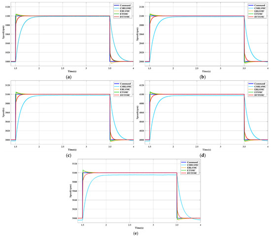
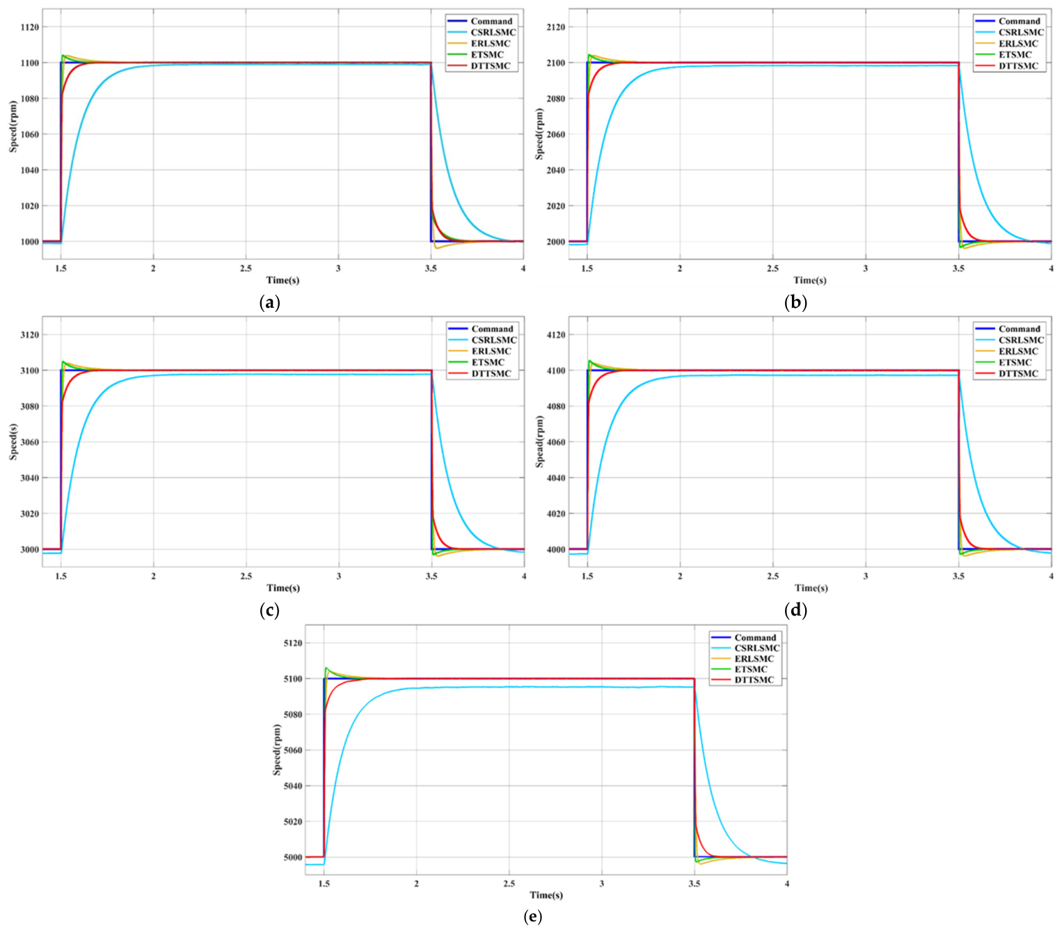
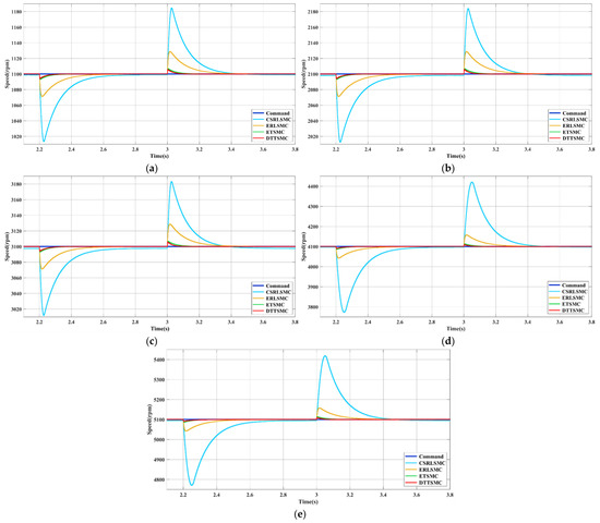
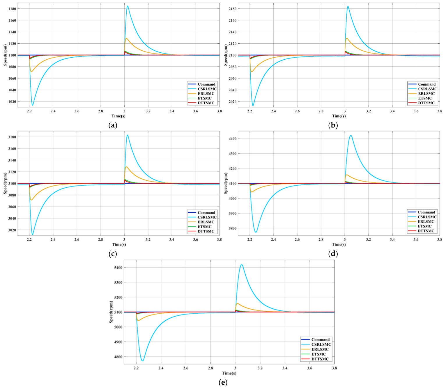
The test motor in this paper uses the AM-2200H permanent magnet BLDCM (Adlee Powertronic Co., Ltd., Taichung, Taiwan) [27], and its specifications are shown in Table 1. Since its rated speed is 6000 rpm, the speed range is set to 0~6000 rpm. Based on this, the parameters for the gain variations in each interval in Table 2 and Table 3 are determined through the aforementioned steps. Then, Matlab/Simulink is used to conduct the speed control simulation verification of the ELDCM drive system. This paper will compare the speed control performance of the ELDCM using four controllers: decision tree theory with sliding mode controller (DTTSMC), constant speed reaching law sliding mode controller (CSRLSMC), exponential reaching law sliding mode controller (ERLSMC), and extension theory with sliding mode controller (ETSMC). Among them, the ETSMC calculates the dynamic trajectory control gain of the SMC through extension theory to adjust the sliding mode dynamic trajectory function, enabling it to possess robust control performance. To ensure a fair comparison of control performance under identical conditions, the parameters of all compared controllers were appropriately tuned. Specifically, the control gains for both the CSRLSMC and the ERLSMC were systematically determined through a trial-and-error method to achieve an optimal balance among transient tracking speed, overshoot, and steady-state chattering across the tested operating range. Meanwhile, the parameters of the ETSMC are configured according to the design methodology presented in previous research [9]. Figure 4a–e shows the speed command tracking responses of the BLDCM for a change of 100 rpm at different speed commands (1000, 2000, 3000, 4000, 5000 rpm); and Figure 5a–e shows the load regulation responses of the brushless DC motor under different speed commands (1100, 2100, 3100, 4100, 5100 rpm). Among them, Figure 5a–c are the simulation results when the load change is 1 N-m at speed commands (1100, 2100, 3100 rpm), while Figure 5d,e are the simulation results when the load change is 2 N-m at speed commands (4100, 5100 rpm). From the simulation results in Figure 4 and Figure 5, it can be observed that the SMC adopting only the CSRLSMC lacks an integral effect, so it cannot guarantee stable tracking on the speed command. In terms of load regulation response, it also requires a longer recovery time and causes an excessive speed drop. In addition, although the SMC adopting only the ERLSMC has a faster response compared to the one adopting only the constant speed reaching law, overshoot occurs. Compared to the SMC adopting only the ERLSMC, the ETSMC has a relatively fast tracking response, and the time taken for the recovery response under load changes is shorter with a smaller amplitude. However, its speed tracking response for small-amplitude changes is still insufficient, and overshoot still exists. By employing the DTT to determine the three gains of the SMC, the overshoot associated with the exponential reaching law is effectively reduced, and enhanced control performance in load regulation is obtained compared with the remaining three. Furthermore, because the q-axis current is directly proportional to the electromagnetic torque, it is utilized to evaluate the torque transient responses. The simulation results demonstrate that under both speed command step changes and load disturbances, the proposed controller achieves a more rapid torque response with significantly reduced transient oscillations compared to the other control strategies.
Table 1.
Specifications of the adopted ELDCM.
Table 2.
Sliding mode dynamic trajectory control gain variation and exponential reaching gain variation for the 10 error intervals.
Table 3.
SMC constant speed reaching gain variation for the 10 error intervals.
Figure 4.
Comparison of tracking responses under different speed commands among the proposed DTTSMC, the CSRLSMC, the ERLSMC, and the ETSMC (The speed command increases by 100 rpm at 1.5 s, and returns to the original speed command at 3.5 s): (a) 1000 → 1100 → 1000 rpm, 1 N-m; (b) 2000 → 2100 → 2000 rpm, 1 N-m; (c) 3000 → 3100 → 3000 rpm, 1 N-m; (d) 4000 → 4100 → 4000 rpm, 1 N-m; (e) 5000 → 5100 → 5000 rpm, 1 N-m.
Figure 5.
Comparison of load regulation responses at different speed commands among the proposed DTTSMC, the CSRLSMC, the ERLSMC, and the ETSMC (The load is applied from no-load at 2.2 s under different speed commands, and returns to no-load at 3 s): (a) 1100 rpm, 0 → 1 → 0 N-m; (b) 2100 rpm, 0 → 1 → 0 N-m; (c) 3100 rpm, 0 → 1 → 0 N-m; (d) 4100 rpm, 0 → 2 → 0 N-m; (e) 5100 rpm, 0 → 2 → 0 N-m.
As shown in Table 2 and Table 3, the significant gain jumps across adjacent intervals are designed for dynamic adaptability. The base values of these gains, including , , and , are tuned via trial-and-error within Lyapunov stability boundaries. Subsequently, the CART algorithm objectively identifies optimal speed error split points to precisely map these gains. During severe disturbances with large transient errors, these abrupt gain jumps provide a powerful corrective effort. Conversely, in steady-state small-error intervals, the gains drop sharply to eliminate the chattering inherent to sliding mode control. Finally, regarding physical units, the speed error e is measured in rpm, while the gains act as proportional scaling factors within the discrete control loop, tailored specifically to the parameters of the tested BLDCM.
Table 4, Table 5 and Table 6 present the quantitative performance of the four controllers under various operating conditions. Specifically, Table 4 evaluates the speed tracking performance—focusing on overshoot and settling time—in response to a 100 rpm step change, which is applied at 1.5 s and removed at 3.5 s, across base speeds ranging from 1000 to 5000 rpm under a constant 1 N-m load. Furthermore, Table 5 and Table 6 demonstrate the load regulation performance, evaluated by maximum speed drop and recovery time. Table 5 details the response to a 1 N-m load disturbance applied at 2.2 s and removed at 3.0 s for base speeds of 1100, 2100, and 3100 rpm. Finally, Table 6 details the response to a 2 N-m load disturbance applied at 2.2 s and removed at 3.0 s for base speeds of 4100 and 5100 rpm. These quantitative results confirm that the proposed DTTSMC significantly outperforms the other three controllers in both speed tracking and load regulation, achieving zero overshoot alongside the fastest settling and recovery times across all tested conditions.
Table 4.
Speed tracking comparison for load = 1 N-m.
Table 5.
Comparison of load regulation under 0 → 1 → 0 N-m conditions.
Table 6.
Comparison of load regulation under 0 → 2 → 0 N-m conditions.
5. Conclusions
This study addresses BLDCM speed regulation by substituting the conventional P-I speed controller in traditional FOC with a control scheme that integrates DTT and the exponential reaching law of a SMC. The proposed robust controller employs DTT to configure three essential gains of the SMC, thereby fine-tuning both the sliding mode dynamic trajectory function and the exponential reaching law function. As a result, the BLDCM drive system achieves superior speed tracking performance under diverse operating conditions compared with CSRLSMC, ERLSMC, and ETSMC, enabling rapid and stable command following. In addition, the controller demonstrates enhanced load regulation capability relative to the three existing improved SMCs. It effectively suppresses the overshoot typically caused when only the exponential reaching law is applied, while also resolving the slow response issue inherent in conventional SMCs. Consequently, the robust controller that combines DTT with sliding mode theory and the exponential reaching law improves both speed command tracking and load regulation responses. Moreover, the proposed control law is computationally efficient and does not rely on extensive training data, making it straightforward to implement.
Author Contributions
K.-H.C. manages the project and completed the formal analysis of the sliding mode controller. K.-H.C. also plans the project and writes, edits and reviews the manuscript. Y.-H.G. is responsible for the software program and simulation results validation. C.-T.H. completed the formal analysis of the decision tree theory. All authors have read and agreed to the published version of the manuscript.
Funding
The authors gratefully acknowledge the support and funding of this project by the National science and Technology Council, Taiwan, under Grant Number NSTC 114-2221-E-167-003-MY2.
Institutional Review Board Statement
Not applicable.
Informed Consent Statement
Not applicable.
Data Availability Statement
The original contributions presented in this study are included in the article. Further inquiries can be directed to the corresponding author.
Conflicts of Interest
The authors declare no conflicts of interest.
Nomenclature
| Acronyms | ||
| BLDCM | : | brushless DC motor |
| FOC | : | field-oriented control |
| DTT | : | decision tree theory |
| SMT | : | sliding mode theory |
| CART | : | classification and regression tree |
| ERLSMC | : | exponential reaching law sliding mode controller |
| MSE | : | mean squared error |
| ERL | : | exponential reaching law |
| CSRL | : | constant speed reaching law |
| ETERL | : | extension theory combined with exponential reaching law |
| P-I | : | proportional-integral |
| FLT | : | fuzzy logic theory |
| ET | : | extension theory |
| 2DOFC | : | two-degree-of-freedom controller |
| SVPWM | : | space vector pulse width modulation |
| MTPA | : | maximum torque per ampere |
| MAE | : | mean absolute error |
| SMC | : | sliding mode controller |
| DTTSMC | : | decision tree theory with sliding mode controller |
| CSRLSMC | : | constant speed reaching law sliding mode controller |
| Symbols | ||
| : | stator fluxes of the d-axis and q-axis | |
| : | flux linkage | |
| : | stator voltages of the d-axis and q-axis | |
| : | stator resistance | |
| : | stator currents of the d-axis and q-axis | |
| : | electrical angular velocity | |
| : | stator inductances of the d-axis and q-axis | |
| : | electromagnetic torque | |
| : | number of poles | |
| : | moment of inertia | |
| : | mechanical rotational speed | |
| : | load torque | |
| : | moment of inertia | |
| : | proportion of the i-th category in node t | |
| : | number of categories | |
| : | left child node and right child node | |
| : | number of samples in node t | |
| : | number of samples in the left and right child nodes | |
| : | actual value of sample | |
| : | sample mean in the node (i.e., the average predicted value) | |
| s | : | sliding line function |
| : | sliding line control gain | |
| : | state variable functions | |
| : | reaching law function | |
| : | constant speed reaching gain | |
| : | exponential reaching gain | |
| : | sign function | |
| : | constant of integration | |
| N | : | number of samples in the value range of 1 to n |
| : | number of features | |
| : | initial value of the sliding mode dynamic trajectory control gain | |
| : | variation amount of the control gain |
References
- Wang, M.; Chen, Z. Research on Permanent Magnet Structure of Permanent Magnet Synchronous Motor for Electric Vehicle. In Proceedings of the 2nd International Conference on Electrical Engineering and Control Science (IC2ECS), Nanjing, China, 16–18 December 2022; pp. 990–993. [Google Scholar]
- Lee, C.I.; Jang, G.H. Experimental Measurement and Simulated Verification of the Unbalanced Magnetic Force in Brushless DC Motors. IEEE Trans. Magn. 2008, 44, 4377–4380. [Google Scholar] [CrossRef] [Scilit]
- Prabudha, B.V.; Balamurugan, A.; Selvathai, T.; Reginald, R.; Varadhan, J. Evaluation of Different Vector Control Methods for Electric Vehicle Application. In Proceedings of the 2nd International Conference on Power and Embedded Drive Control (ICPEDC), Chennai, India, 21–23 August 2019; pp. 273–278. [Google Scholar]
- Bhatti, S.A.; Malik, S.A.; Daraz, A. Comparison of P-I and I-P controller by Using Ziegler-Nichols Tuning Method for Speed Control of DC Motor. In Proceedings of the International Conference on Intelligent Systems Engineering (ICISE), Islamabad, Pakistan, 15–17 January 2016; pp. 1–5. [Google Scholar]
- Murali, S.B.; Rao, P.M. Adaptive Sliding Mode Control of BLDC Motor Using Cuckoo Search Algorithm. In Proceedings of the 2nd International Conference on Inventive Systems and Control (ICISC), Coimbatore, India, 19–20 January 2018; pp. 989–993. [Google Scholar]
- Dat, N.V.; Nguyen, V.T.; Nguyen, H.N. Adaptive Sliding Mode-based Observer and Current Controller for Torque Balance Control Strategy of Coaxial BLDC Motor. IEEE Access 2024, 12, 11524–11535. [Google Scholar]
- Li, H.; Yu, J.; Wang, G. Subsection Nonsingular Terminal Sliding Mode Control for Single Winding Broken Fault of In-Wheel-Motor of Electric Vehicle. IEEE Access 2017, 5, 15473–15482. [Google Scholar]
- Ali, M.A.E.M.; Ali, M.A.M.; Awadallah, K.M. Super Twisting Sliding Mode Controllers Based Direct Torque Control of BLDC Motor. IEEE Access 2024, 12, 4512–4523. [Google Scholar]
- Kürkçü, B.; Kasnakoğlu, C.; Efe, M.Ö. Disturbance/Uncertainty Estimator Based Integral Sliding-Mode Control. IEEE Trans. Autom. Control 2018, 63, 3940–3947. [Google Scholar]
- Qi, C.; Xie, J.; Mao, H.; Xie, Q. Condition Assessment of Valve-side Bushing of Converter Transformer Based on Extension Theory. In Proceedings of the IEEE International Conference on High Voltage Engineering and Application (ICHVE), Beijing, China, 6–10 September 2020; pp. 1–6. [Google Scholar]
- Wu, H.Q.; Chen, Y.W.; Liu, R. College Education Outcome Expectation and Proactive Personality as Predictors of Chinese College Students’ Learning Motivation, Career Adaptability as a Mediator. In Proceedings of the International Conference on Modern Education and Information Management (ICMEIM), Dalian, China, 25–27 September 2020; pp. 716–721. [Google Scholar]
- Lu, S.; Tang, X.; Song, B.; Zhou, B. An Optimal Fuzzy-PI Controller for the High-Performance Speed Control of a PMSM. In Proceedings of the 2nd International Conference on Instrumentation, Measurement, Computer, Communication and Control, Harbin, China, 8–10 December 2012; pp. 1503–1507. [Google Scholar]
- Chao, K.H.; Hsieh, C.T.; Chen, X.J. A Robust Controller Based on Extension Sliding Mode Theory for Brushless DC Motor Drives. Electronics 2024, 13, 4028. [Google Scholar] [CrossRef] [Scilit]
- Chao, K.H.; Chang, C.L. Design of a Robust Controller for Induction Motor Drive Systems Based on Extendable Fuzzy Theory. Mathematics 2024, 12, 3235. [Google Scholar] [CrossRef] [Scilit]
- Wang, J.; Ye, J.; Yan, R. The Magnetostatic Simulation and Determination of Magnetic Components for an External Ventricular Drainage Device. In Proceedings of the 40th Chinese Control Conference (CCC), Shanghai, China, 26–28 July 2021; pp. 6386–6391. [Google Scholar]
- Xie, T.; Kuai, Z.; Ye, X.; Zhu, L.; Guo, K.; Shi, S. Coordinate Conversions and Deviation Analysis in Multi-source Data Fusion. In Proceedings of the 2nd China International SAR Symposium (CISS), Shanghai, China, 3–5 November 2021; pp. 1–3. [Google Scholar]
- Liu, C.H. AC Motor Control: The Principles of Vector Control and Direct Torque Control, 4th ed.; Tonghua Books Co., Ltd.: Taipei, Taiwan, 2007; pp. 33–217. [Google Scholar]
- Kishore, N.; Shukla, K.; Gupta, N. A Novel Three-phase Multilevel Inverter Cascaded by Three-phase Two-level Inverter and Two Single-phase Boosted H-bridge Inverters. In Proceedings of the IEEE PES Innovative Smart Grid Technologies-Asia (ISGT Asia), Singapore, 1–5 November 2022; pp. 330–334. [Google Scholar]
- Butt, C.; Hoque, M.A.; Rahman, M.A. Simplified Fuzzy Logic Based MTPA Speed Control of IPMSM Drive. In Proceedings of the 38th IAS Annual Meeting on Conference Record of the Industry Applications Conference, Salt Lake City, UT, USA, 12–16 October 2003; pp. 499–506. [Google Scholar]
- Luo, N.; Zhang, L. Chaos Driven Development for Software Robustness Enhancement. In Proceedings of the 9th International Conference on Dependable Systems and Their Applications (DSA), Urumqi, China, 4–5 August 2022; pp. 1029–1034. [Google Scholar]
- Sun, J.; Jiang, N.; Sun, G.; Huang, W. Analysis of CART Algorithms in Data Mining. In Proceedings of the 2nd International Conference on Machine Learning, Cloud Computing and Intelligent Mining (MLCCIM), Jiuzhaigou, China, 25–29 July 2023; pp. 548–553. [Google Scholar]
- Xie, H.; Shang, F. The Study of Methods for Post-pruning Decision Trees Based on Comprehensive Evaluation Standard. In Proceedings of the 11th International Conference on Fuzzy Systems and Knowledge Discovery (FSKD), Xiamen, China, 19–21 August 2014; pp. 903–908. [Google Scholar]
- Variable Structure Control System. Available online: https://www.youtube.com/watch?v=vc76WZ0AQcY&list=PLj6E8qlqmkFuIY_c3QvyBFTBiWhqN1Fm0&ab_channel=NYCUOCW (accessed on 15 April 2024).
- Chao, K.H.; Huang, K.H.; Guo, Y.H. Design of a Brushless DC Motor Drive System Controller Integrating the Zebra Optimization Algorithm and Sliding Mode Theory. Electronics 2025, 14, 3353. [Google Scholar] [CrossRef] [Scilit]
- Zhang, J.; Liu, B.; Jiang, Z.; Hu, H. The Application of Sliding Mode Control with Improved Approaching Law in Manipulator Control. In Proceedings of the 13th IEEE Conference on Industrial Electronics and Applications (ICIEA), Wuhan, China, 31 May–2 June 2018; pp. 807–812. [Google Scholar]
- Bodur, F.; Kaplan, O. A Novel Sliding Mode Control Based on Super Twisting Reaching Law for PMSM Speed Controller with Fixed-time Disturbance Observer. In Proceedings of the 12th International Conference on Renewable Energy Research and Applications (ICRERA), Oshawa, ON, Canada, 29 August–1 September 2023; pp. 563–568. [Google Scholar]
- The AM2200H BLDC Motor Supply Produced by Adlee Powertronic Co., Ltd. Available online: https://www.adlee.com/zh-tw/product-552515/%E5%B7%A5%E6%A5%AD%E7%94%A8%E7%9B%B4%E6%B5%81%E7%84%A1%E5%88%B7%E9%A6%AC%E9%81%94.html (accessed on 8 May 2024).

Disclaimer/Publisher’s Note: The statements, opinions and data contained in all publications are solely those of the individual author(s) and contributor(s) and not of MDPI and/or the editor(s). MDPI and/or the editor(s) disclaim responsibility for any injury to people or property resulting from any ideas, methods, instructions or products referred to in the content. |
© 2026 by the authors. Licensee MDPI, Basel, Switzerland. This article is an open access article distributed under the terms and conditions of the Creative Commons Attribution (CC BY) license.