


Abstract
This article presents, for the first time, a new approach to building quantum circuits for the initialization of two multi-qubit superpositions, namely, two different superpositions in one circuit, not in two separate circuits. For this, we introduce the concept of the discrete two signal-induced heap transformation (D2siHT). This transformation is generated by two signals, or vectors, which we call generators. The quantum analogue of the D2siHT is described. It allows us to build a quantum circuit to transform two superpositions and into the first conventual basis states and , respectively. Therefore, we can build a single quantum circuit to initiate two multi-qubit superpositions and from the basis states and , respectively. Examples with quantum circuits for the preparation and transformation of two 2- and 3-qubit superpositions are described in detail. The results of circuit simulation using Qiskit are also presented. The main characteristic of the D2siHT is its path of processing the data of two generators and input qubits. We consider different paths to effectively compute the D2siHT. Such paths can reduce, for instance, the depth of the resulting quantum circuits, which can lead to a reduction in execution times and susceptibility to decoherence and noise. Multi-qubit superpositions are considered with real amplitudes, but the presented approach can be extended to initiate two such superpositions with complex amplitudes, as well.
1. Introduction
In quantum computation, the main objects are qubits and the operations performed on them, which can only be unitary. Qubits of number are mathematically represented as a linear superposition of possible basis states with amplitudes describing the probabilities of being in one of these states. The preparation of such superpositions representing different data, including signals and images, is an especially important task, and it is the first task in quantum computing [1,2,3,4,5,6,7,8,9,10,11]. The traditional approach to initiating a multi-qubit superposition starts with composing a unitary transformation of into the conventual basis state, for instance, the first one, as . Then, a quantum circuit is built to calculate the inverse transform, . And because the operation is unitary, the inverse operator is easy to calculate. Based on this approach, another important task of transferring one multi-qubit superposition to another, , can be accomplished as well. This operation is fulfilled by two transformations to the same conventual basis state, and . This results in the traditional two-stage approach with the transformation , which is known as the state-to-state preparation task. To initiate quantum superpositions, different methods can be used. We mention the Householder transformations [12,13,14] and Given rotations [15,16]. Methods with Givens rotations are simple, and many quantum circuits have been developed [17,18,19]. These circuits contain many permutations, namely, the CNOT and controlled CNOT operations. Therefore, much attention has been paid to minimizing the number of such gates. It was found that the number of elementary rotation gates is around , and that of CNOTs is [20,21,22]. Such a large number of CNOTs is understandable because quantum circuits require all gates to operate on adjacent, or nearest-neighbour, bit planes (BPs). Permutations with Gray code are used for this purpose [22,23]. Recently, it was shown that a multi-qubit superposition can be obtained from another multi-qubit superposition in only one step. Namely, the transformation can be accomplished without transferring the superpositions to the basis state [24]. This effective method is based on the discrete signal-induced heap transform (DsiHT) and uses only rotation gates (in the real case of amplitudes) without any permutation [25].
In this work, we analyze the method of composing a unitary transformation which is composed of 3D rotations. Namely, we introduce the discrete two signal-induced heap transform (D2siHT), which is generated by two generators. These unitary transformations can be used to initiate two different multi-qubit superpositions with real amplitudes. The quantum analogue of the -point D2siHT is the -qubit quantum two signal-induced heap transform (Q2siHT). The key contributions of this work are the following:
- We develop a unitary transformation generated by two vectors, or two quantum superpositions, by using 3D rotations.
- We propose quantum circuits, each of which allows us to calculate two different multi-qubit superpositions.
- We present examples with different paths for initiating two 2- and 3-qubit superpositions. These circuits are constructed, tested, and validated using the Qiskit framework.
The rest of this paper is organized as follows. The DsiHT with one generator is described in Section 2. In Section 3, the new concept of the D2siHT is presented, and examples are described in detail. In Section 4, we discuss the importance of the path in the initialization of the qubit superpositions with examples for 2- and 3-qubit superpositions. Finally, the presented circuits are analyzed using the Qiskit framework in Section 5.
2. The DsiHT with One Generator
The DsiHT is defined by a special selection of parameters that are initiated by vector-generators through so-called decision equations [26]. Let , …, ) be parameterized functions of an -dimensional vector variable , where , and . Parameters are chosen to adjust the transformation
to make it, for instance, unique, separable, unitary, and fast. The transformation is considered separable, which means that there exist such transformations , , …, that
where is a permutation of numbers
Here, we limit ourselves with the case when each transformation changes only two components of the vector . Thus, is described as a transformation
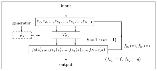
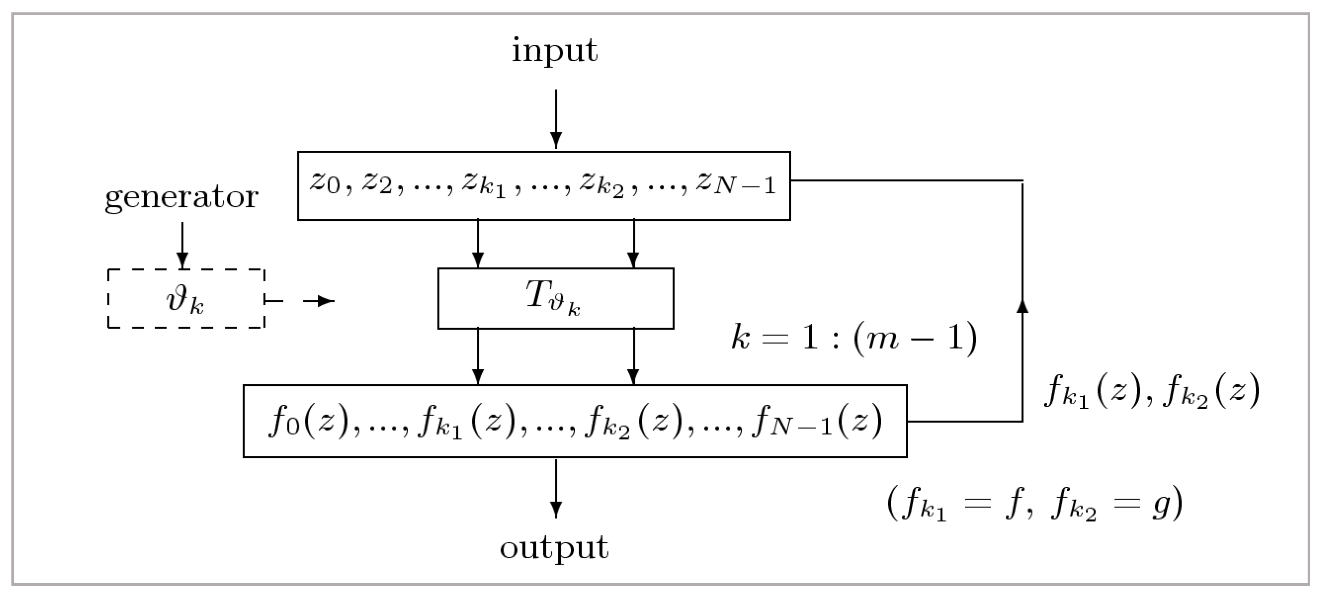
where the pair of numbers is uniquely defined by , and . This means that these transformations are isomorphic to the two-dimensional transformations (see Figure 1)
Figure 1.
A block diagram of the DsiHT.
We add one more simplification by assuming that all the first functions in this equation are equal to a function , and all functions are equal to a function . Then, the problem of the construction of the -D transformation is reduced to defining unitary transformations
And finally, we propose the following method of selecting parameters , . The selection of these parameters is based on specified vector-generators, the number of which is defined through a given system of decision equations, to achieve the uniqueness of parameters and desired properties of the transformation . The number of decision equations defines the complexity of transformations.
First, we describe the case of two decision equations with one vector-generator . We assume that the functions and are linear,
where the coefficients and are functions of Thus, we have two functions and The parameter refers to the rotation parameter, such as the angle, and and the coordinates of the point on the plane. These variables may have other meanings as well. It is assumed that, for a given set of parameters the equation has a unique solution with respect to , for each point on the plane or its chosen subset. The system of equations
is called the system of decision equations. The value of is calculated from the second equation, which we call the angular equation. Then, the value of is calculated from the given input and . It is also assumed that the two-point transformation
which is derived (or whose matrix is calculated) from the given decision equations by
and which we call the basic transformation, is unitary. The transformations are the little building blocks from which we construct a unitary transformation.
As an example, we consider the decision equations with the elementary rotations
The basis transformation is defined as the rotation of the point to the horizontal ,
The rotation angle is calculated by
and when Here, the following condition is required: . Then, the basic transformations in Equation (9) are defined from the decision equations
The special case when all parameters leads to the -point DsiHT, which operates on the generator as Here, the apostrophe denotes the transpose operation. The transform collects the generator’s energy in one place or heap. The order of processing the components of the generator, which is called the path of the transformation, can be chosen in different ways. For instance, the following path can be considered
Here, at each step, the first value of the generator is updated as . The -point DsiHT with this natural order of processing the components of the generators is called the weak DsiHT [26]. The transform of an input is processed with the same path,
Thus, the concept of the -point DsiHT is based on creating a unitary transformation from a given signal or vector (or a multi-qubit superposition in quantum computation). The matrix of this transformation is composed of elementary rotations, and the rotation angles are determined by the generator and the path.
Example 1: Consider the generator Seven rotations with angles (in degrees) are used in the calculation of the 8-point weak DsiHT, which has the matrix
The determinant of this matrix is equal to 1, and the first row is the generator .
3. Decision Equations with Two Vector-Generators
In this section, we consider transformations which are defined by three decision equations with two generators. These are equations that allow us to calculate transformation parameters. Obviously, these equations must be solvable. The method of the composition of such transformations is based on the approach described in Section 2, for the DsiHT with one generator and two decision equations. Here, we consider the case when basic transformations operate with only three components of an input vector Namely, at each stage of calculations, two components out of three from stage are updated, and the third one is chosen from the rest of . To avoid complex notations in equations, the same symbols will be used for the original components of the input and for the updated ones. Thus, we consider an isomorphic 3D transformation defined as follows:
where the triple of numbers ) is uniquely defined by . We also assume that the functions , , and are equal to the same functions which we denote by , , and , respectively. The problem of constructing an -point transformation is reduced to defining 3-point basic transformations as
Here, are vector parameters; for instance, when
Rotations in 3D Space
To define a transformation generated by two vectors (generators), we consider two 2D rotations in the 3D space. Namely, we consider the performance of rotations around the - and -axes, and two given vector-generators will be rotated simultaneously to the plane -. In this case, the basic transformation has the form
where is an input vector, and are angle parameters. These parameters are determined by two given vectors and Thus, the transformation is defined by three decision functions , , and . We can also write
It is assumed that parameters can be found from the angular equations
for given parameters and . The transformation is defined by two rotations around the y- and x-axes,
The angular equations for the vector-generators and can be written as
We consider the particular case when It is not difficult to see that angles and , being vector functions of and , are determined from the above angular equations as follows:
and if
To compose the transform of the -dimension vector , we consider two vector-generators and . The order of choosing all triplets ) in Equation (19) is called the path of the D2siHT. We consider the case when the path of the transformation is defined in the natural order, from left to right, as In other words, let us define the following triplets:
when The first two components of each triplet are updated from the -th stage as
Before the last stage of the transform calculation, that is, when , we obtain the following transforms of the generators:
and for the input, Our goal is to transfer these two vectors into the first and second Cartesian unit vectors,
Therefore, the transformation which is applied to the two-dimension vector has the following matrix:
Indeed, it is not difficult to see that
It is assumed that the vectors and are independent. At this stage, the first two components of the transform are processed by this matrix, The -point D2siHT of the input signal is
Thus, the discrete two signal-induced heap transformation (D2siHT) composed of the basic transformations (rotations) is defined as
where the vector triples , , and angles and are determined based on the processing of data and the generators and .
Comment 1: If the vectors and at the last stage of calculation in Equation (27) are dependent, then when In this case, the matrix is considered to be the elementary rotation, and
Two generators and are transformed to the vectors
Comment 2: We may assume that the vector-generators are unit vectors; that is, , and Then, the transforms in Equation (28) can be written as . In the case, when and , such a matrix does not exist. In other words, at the last stage of the DsiHT, it is not possible to find a matrix D such that
Comment 3: All matrices of the transformations in Equation (32), except the matrix , are rotation matrices. Therefore, the D2siHT is not unitary, and its matrix, , has determinant To apply the D2siHT in quantum computation, for the case when is a power of 2, we will replace the matrix with a rotation around the -axis. One of the following transforms is considered:
and
Here, and are the matrices of elementary rotations (the Givens rotations) defined as
and
The angles are calculated by
The normalization of the generators, and , is not required. Thus, the modified -point D2siHT is considered as the transform
where or This can also be written as The transformation is unitary and uses 3D rotations and one 2D rotation. All angles of this transformation can be written as shown in Table 1. Only one of the angles and is used. The total number of angles in the D2siHT is equal to
Table 1.
Encoding data of angles for D2siHT.
Example 2: () Consider two generators and The D2siHT has a matrix calculated by
and it is equal to
Here, for axes and z, the notation is used for the rotation gate that operates on the biplanes and , . All angles for this 8-point transformation are given in Table 2.
Table 2.
Encoding data of angles for 8-point D2siHT.
The transforms of the generators are
The inverse transformation is defined by the matrix
If in the last rotation around the -axis, we use the angle instead of , we obtain a D2siHT with the matrix , in which only the first two rows differ from the matrix in Equation (43),
Then, the transforms of the generators are
If we use the D2siHT in the original form, that is, with the matrix ,
then the matrix of the transform calculated by
changes only in the first two rows in the matrix in Equation (43), as shown below
This transformation is not unitary and over the generators results in the unit vectors and
Example 3: For the case, we can represent two generators and as 4-qubit superpositions
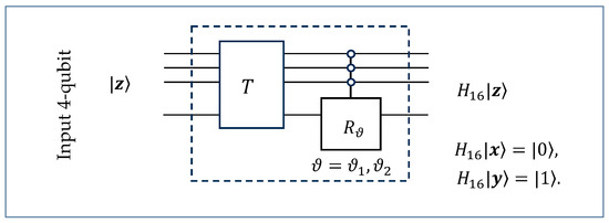
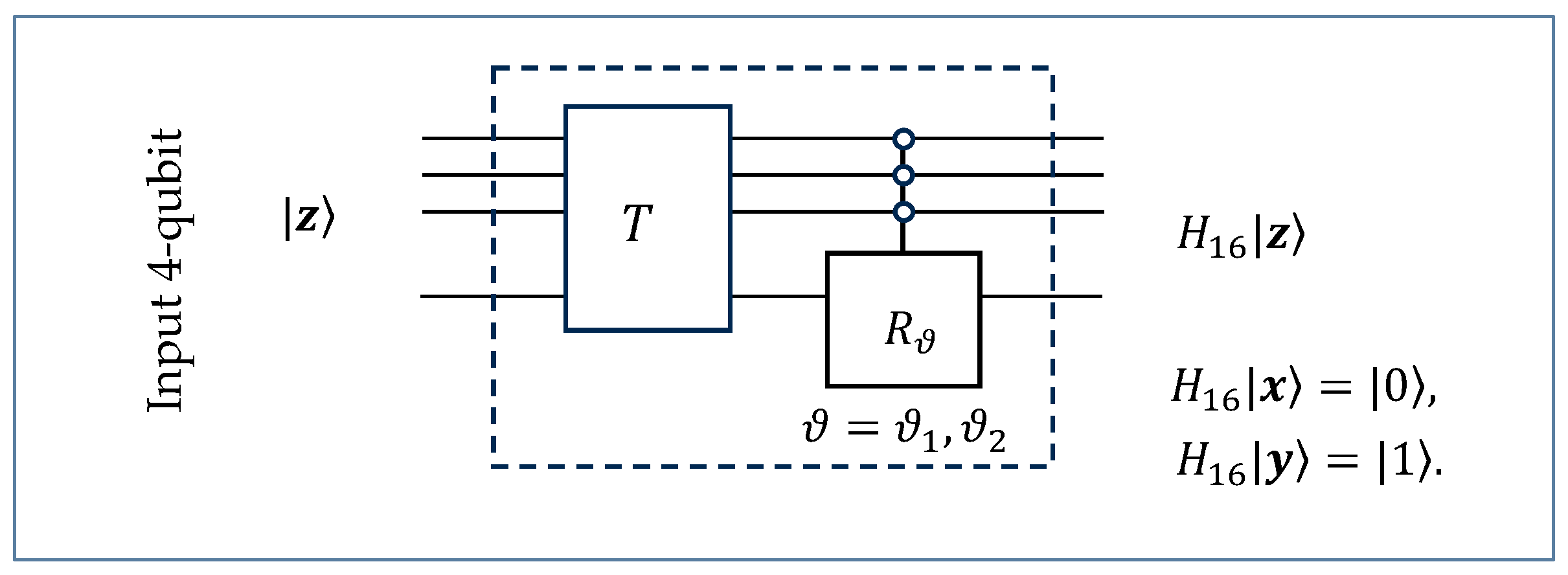
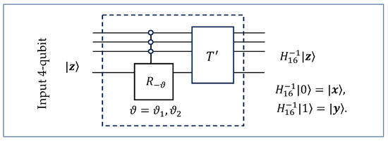
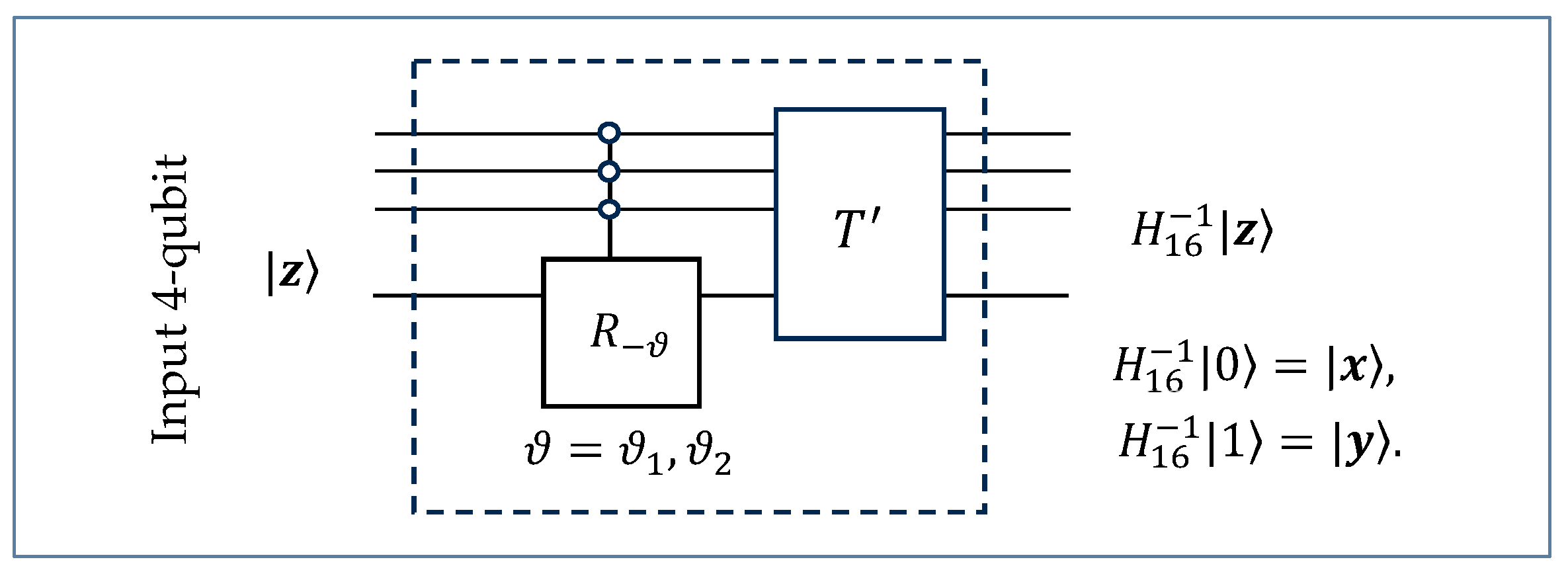
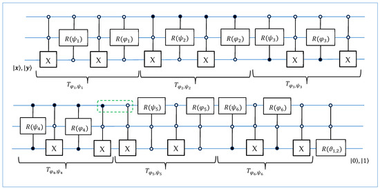
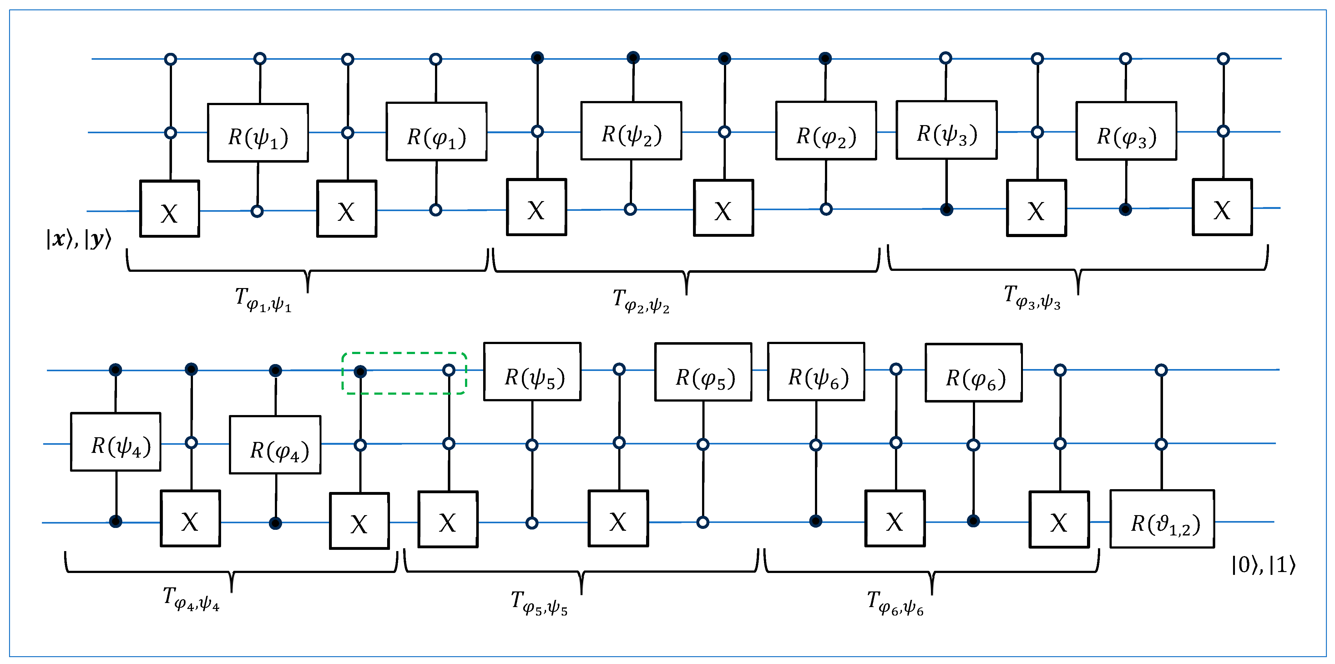
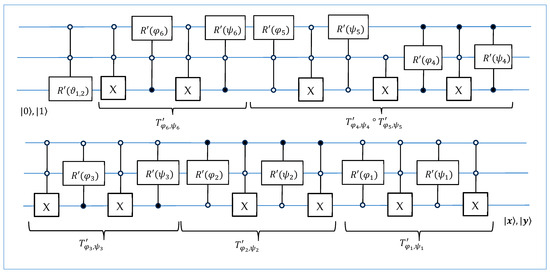
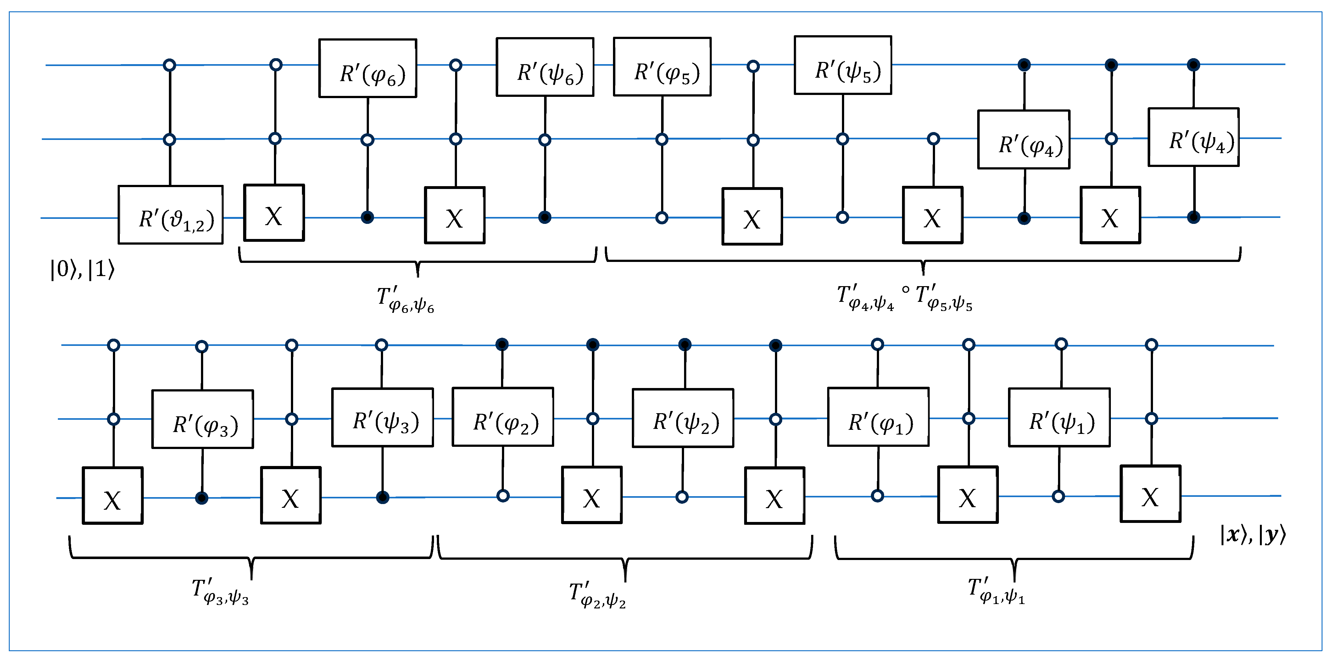
and the input as Here, , , denote the computational basis states [27]. The 4-qubit Q2siHT is described by the matrix of the 16-point D2siHT, , generated by and . The circuit for calculating this transform is given in Figure 2, and the circuit for calculating the inverse 4-qubit Q2siHT is given in Figure 3. The 2D rotation operates on bit planes 0 and 1. Therefore, this rotation is shown in the diagram as three zero-controlled rotation gate.
Figure 2.
A diagram of the 4-qubit Q2siHT.
Figure 3.
A diagram of the inverse 4-qubit Q2siHT.
Example 4: The 4-point D2siHT is described by the following matrix:
where
The rotations and operate on non-adjacent bit planes. We need to move these rotations on adjacent bit planes. For this, we consider the matrix of permutation and write the matrices of these rotations as
Thus,
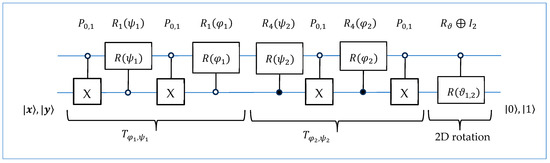
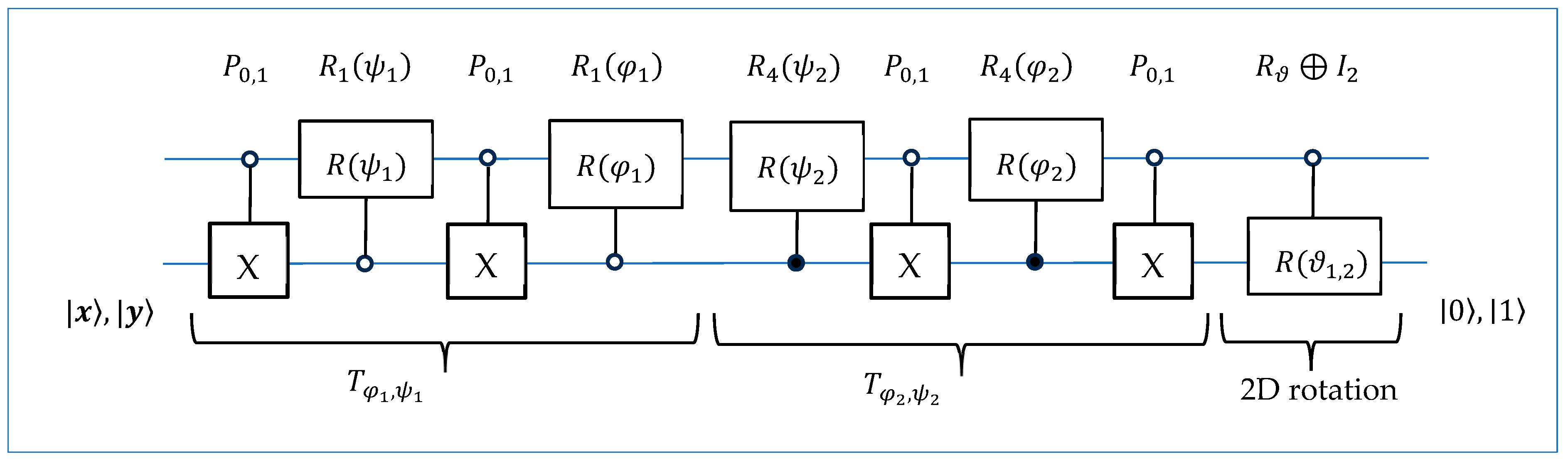
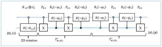
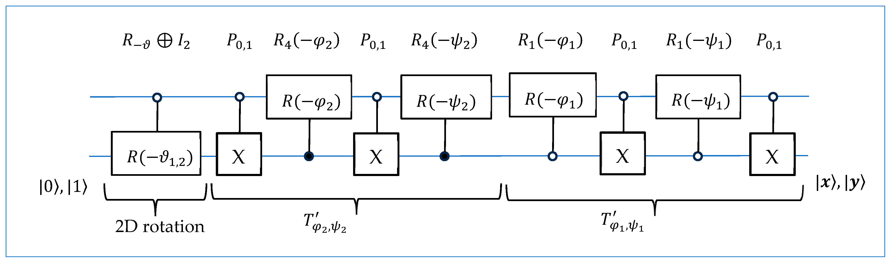
The circuit of this transformation is given in Figure 4. The permutation represents the -controlled X gate or NOT gate; that is, [28].
Figure 4.
The circuit for the 2-qubit D2siHT.
The quantum circuit for the inverse transformation is given in Figure 5. This circuit can be used to initiate the 2-qubit superpositions and from the states and , respectively. Namely, the state when =, and the state , when =.
Figure 5.
The circuit for the preparation of two superpositions and .
Let us consider, for example, the following 2-qubit superpositions:
The angles of the transformation are given in Table 3.
Table 3.
Encoding data of angles for 2-qubit Q2siHT.
The matrices of the D2siHTs are
The transforms of the generators are
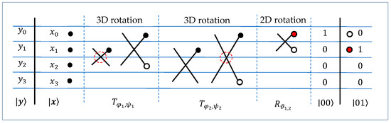
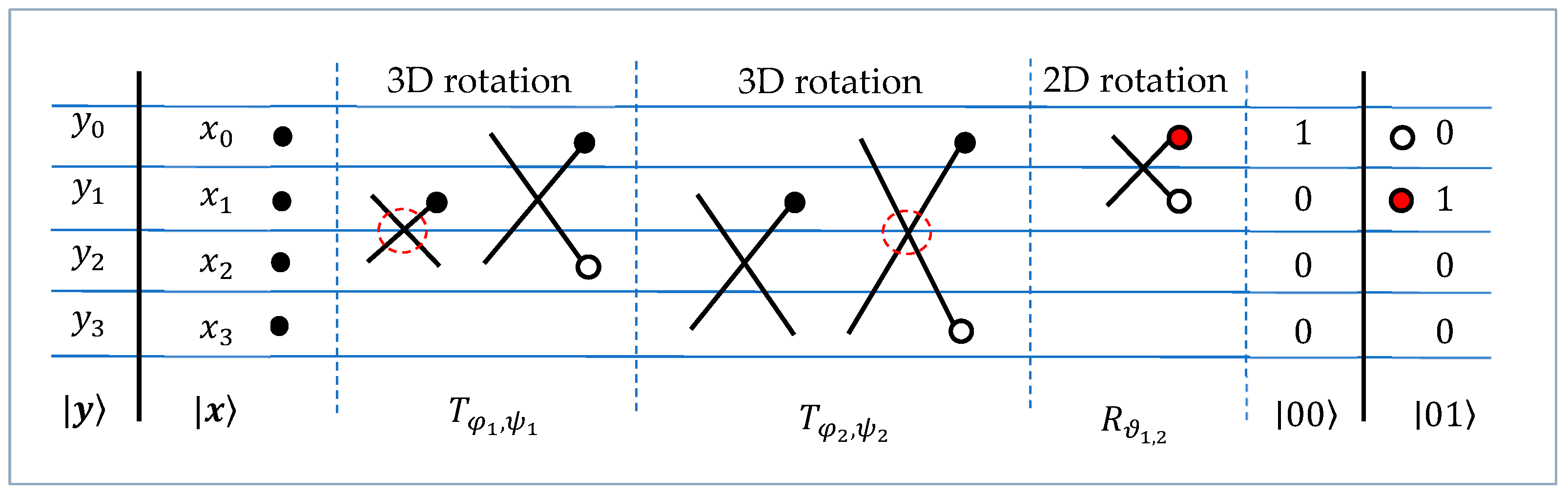
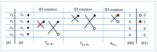
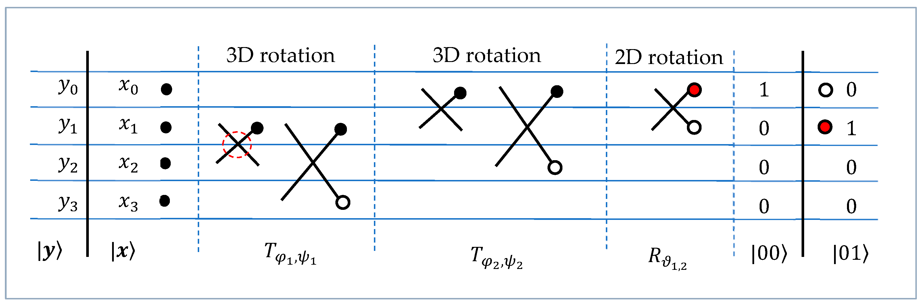
Figure 6 shows the roadmap of this transformation. Five rotations in this transformation are marked with crosses, which we call butterflies. Each 3D rotation is shown as a pair of butterflies. The zero outputs of these butterflies are marked with open circles. The red circles represent the points at which the signal energy is transformed, or the last non-zero outputs of the generator transformations. The butterflies marked with a red dashed circles operate on non-adjacent bit planes. Finding a path with three adjacent bit planes for all 3D rotations is a difficult task and probably impossible.
Figure 6.
The roadmap of the 4-point D2siHT.
Now, we consider the roadmap that is similar to the concept of the strong DsiHT with one generator [25,26]. As shown in Figure 7, the data are processed starting from the last three components of two generators and .
Figure 7.
The roadmap of the 4-point strong D2siHT.
For the above generators, the angles of this transformation are given in Table 4.
Table 4.
Encoding data of angles for 2-qubit strong Q2siHT.
The matrix of the transformation is equal to
4. The 3-Qubit Q2siHT
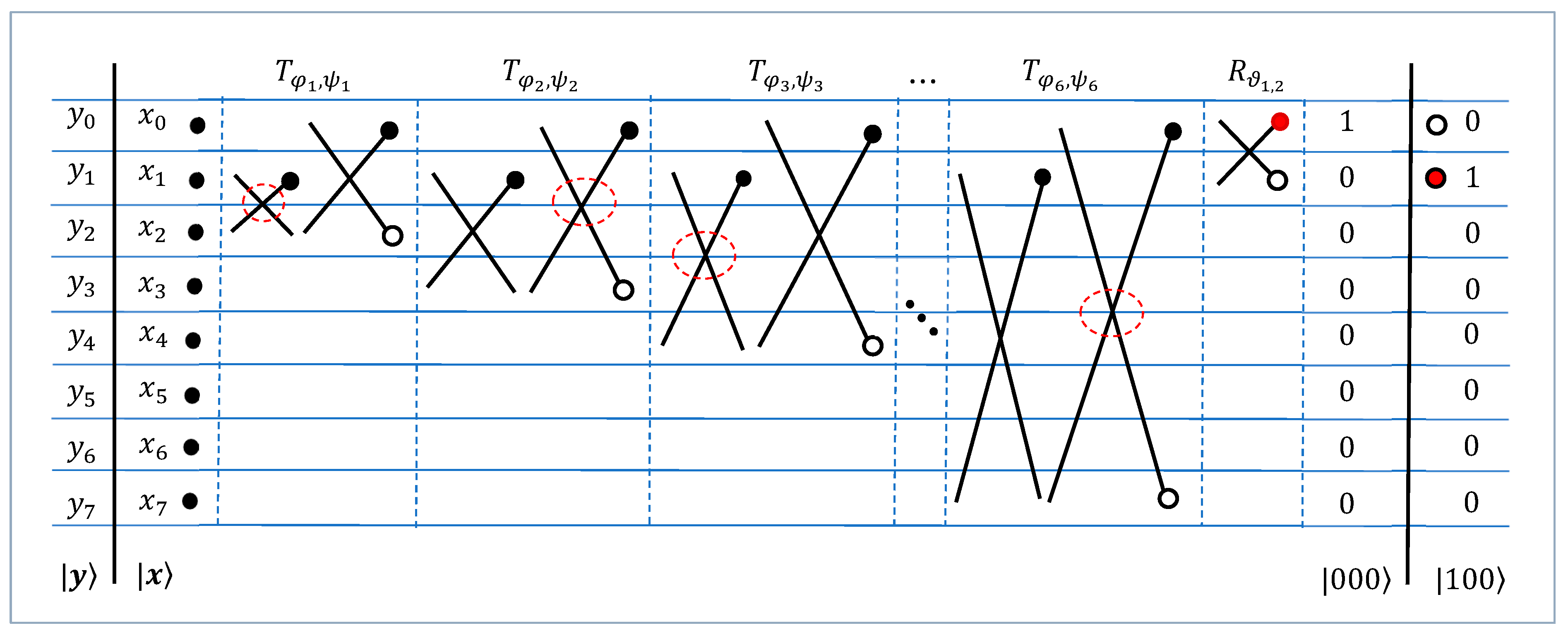
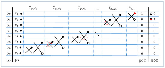
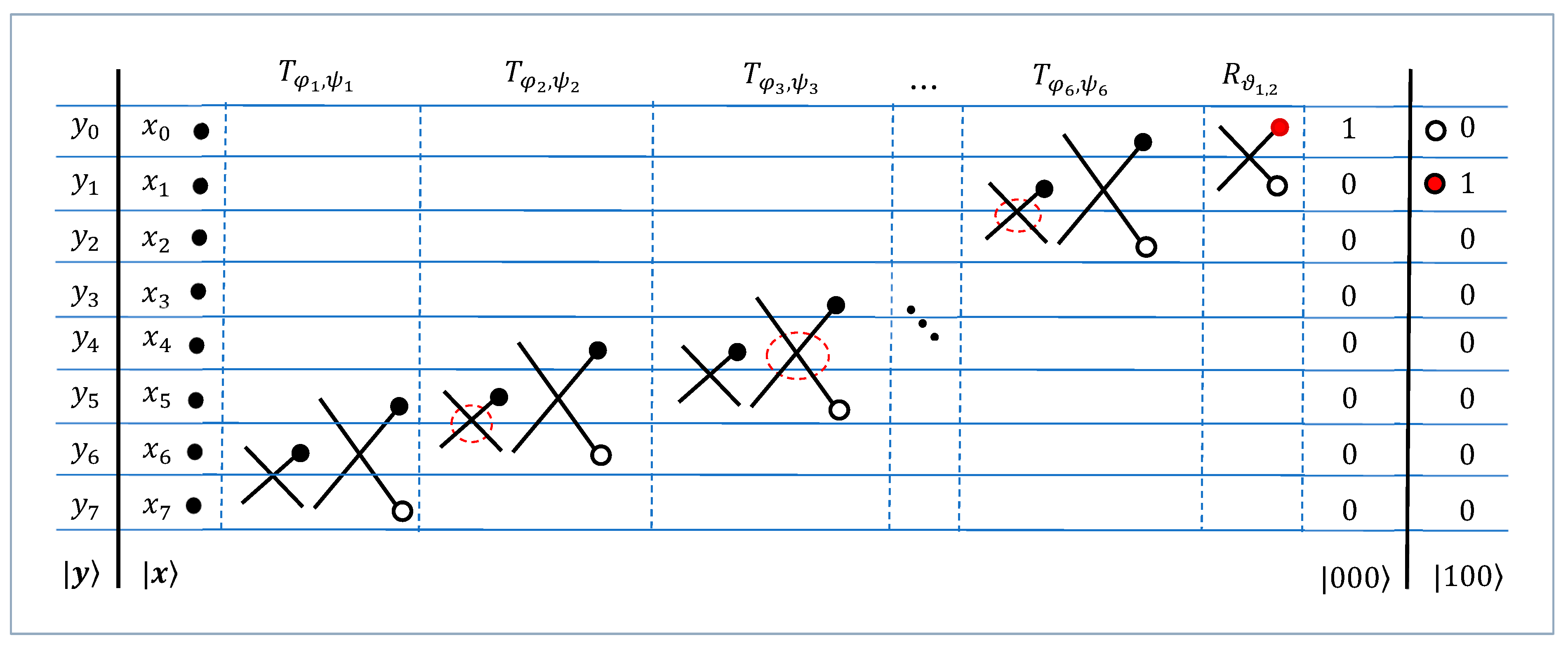
For large values of , many different roadmaps can be used for the -point D2siHT. We describe such roadmaps for the case. First, we consider the roadmap for the 8-point D2siHT (or the 3-qubit Q2siHT) that is used in Example 2. It is shown in Figure 8. One can note that with each step of calculation, control (that is, the butterfly operation) is carried out with increasingly distant signal components, which we attribute to “the weakness” of such a path in the roadmap. This is why we call the transformation with such a path, or path #1, the weak D2siHT.
Figure 8.
The roadmap of the 8-point D2siHT with the natural path or path #1.
Figure 9 shows the roadmap for the 8-point D2siHT, which we call a strong D2siHT. The path of processing data is different. With each step of calculation, the butterflies operate on the nearest component signals, which we consider to be a strong characteristic of such a path. This path will be called path #2.
Figure 9.
The roadmap of the 8-point D2siHT with path #2.
It should be noted that when using path #1 and path #2, there are 3D butterflies whose two 2D butterflies operate on non-disjoint BPs. For instance, when using path #1, the first butterfly in operates on BPs 001 and 110, and the second one operates on BPs 000 and 110. When using path #2, such a 3D butterfly is which operates on BPs 011 and 100 and then on 010 and 100.
Example 5: Let vectors and be two generators considered in Example 2. Then, the 8-point strong D2siHT is described by rotations with the angles given in Table 5.
Table 5.
Encoding data of angles for 8-point strong D2siHT.
The matrix of this transformation is equal to
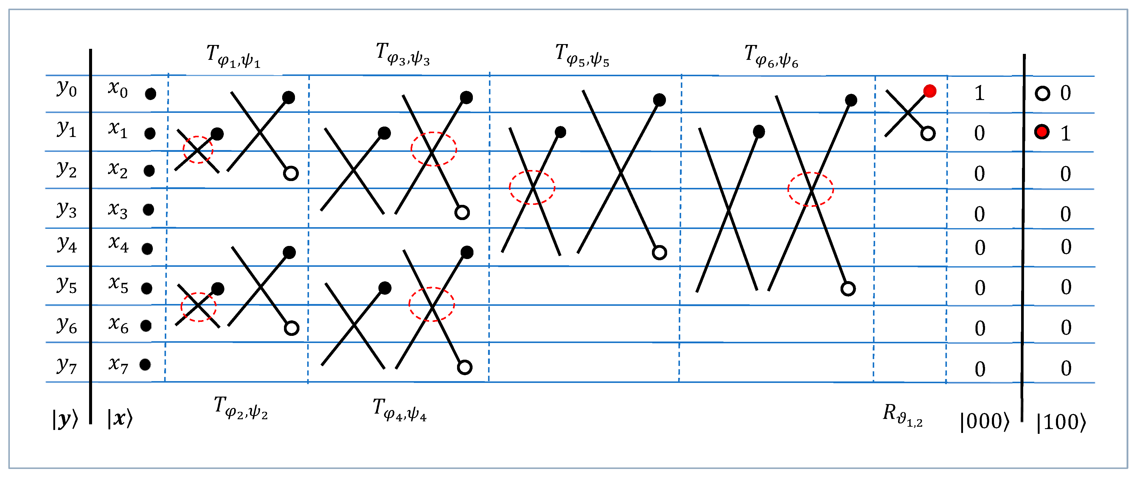
As an example, Figure 10 shows another roadmap of the 8-point transformation.
Figure 10.
The 3rd roadmap of the 8-point D2siHT.
The path with partitioning, or path #3, in this map with five steps of calculations can be considered more effective than path #1, which is used in Example 2. It is not difficult to see that in this roadmap, in all 3D butterflies, only one of two 2D butterflies operates on non-disjoint BPs. This is also true in the general case of The number of stages or the depth of the circuit corresponding to this roadmap is equal to For the roadmaps with paths #1 and #2, the number of stages in the calculations is equal to
We consider the same two generators and that are used in Example 2. The matrix of the 8-point D2siHT with path #3 is equal to
The matrix changed only in the second part, when compared with the matrix in Equation (43). The number of zero coefficients is 18, compared to 15 in and . This is also true in the general case of generators. Each path defines the structure of the transformation matrix. All angles for this 8-point transformation are given in Table 6.
Table 6.
Encoding data of angles for 8-point D2siHT with path #3.
The quantum circuit for the transformation is given in Figure 11. This circuit is composed of 13 controlled rotation gates and 12 controlled NOT gates. All these gates are controlled by two qubits. In the general case, the number of rotation gates to initiate -qubit superposition is equal to plus controlled X gates.
Figure 11.
The quantum circuit for calculating the 3-qubit Q2siHT.
One can note that two controlled X gates connected in series at the junction of the operators and represent one X gate controlled by the second qubit. The circuit for calculating the inverse 3-qubit Q2siHT is given in Figure 12. The inverse rotations are denoted by .
Figure 12.
The quantum circuit for the preparation of two 3-qubit superpositions.
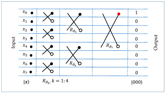
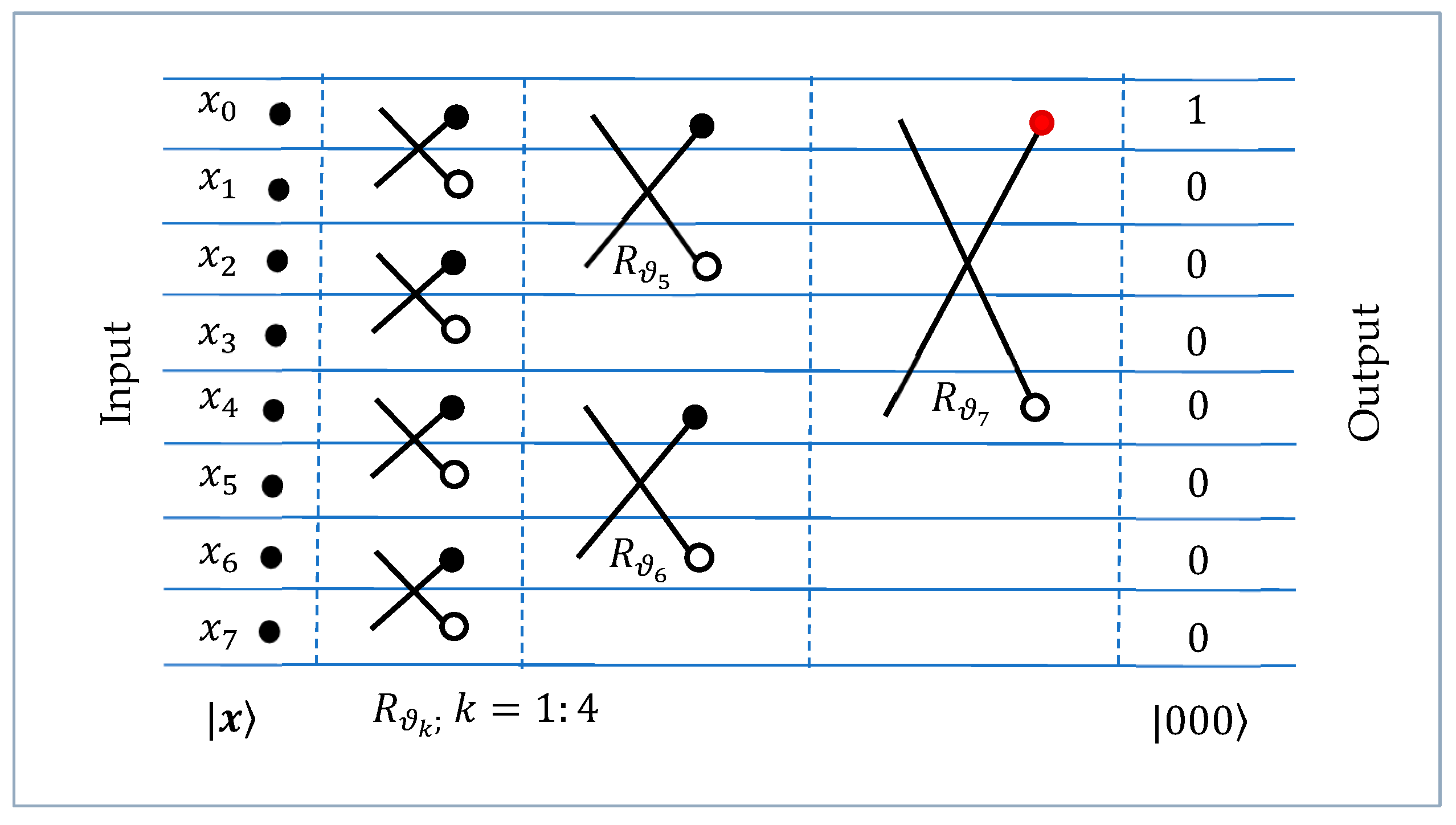
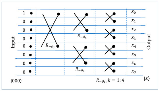
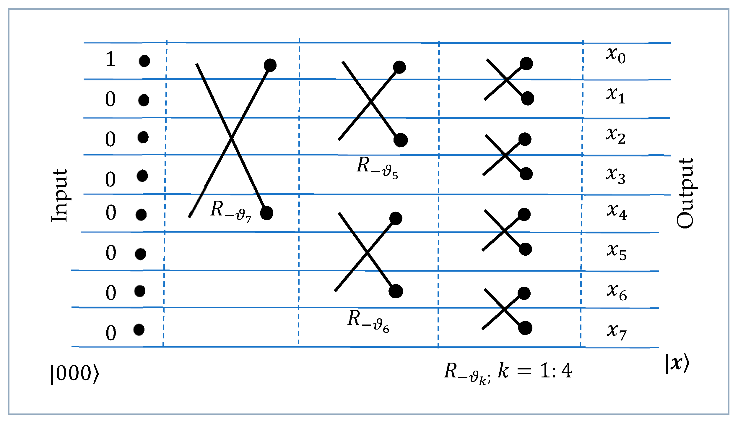
For comparison, we consider the traditional method of the preparation of the 3-qubit superposition by the Givens rotations. For this, we use the 8-point DsiHT with a fast path (for details, see [25]). The roadmap of this transformation of the 8D vector is shown in Figure 13. Seven 2D rotations, or butterflies, are used, and all these rotations operate on the adjacent bit planes.
Figure 13.
The roadmap of the 8-point DsiHT with a fast path.
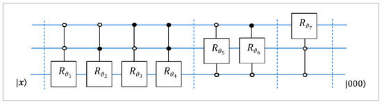
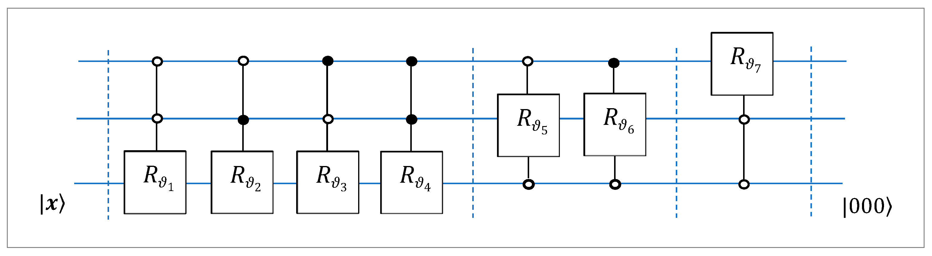
The quantum circuit with seven 2-qubit controlled rotation gates for calculating this transformation, is given in Figure 14. This is a permutation-free circuit.
Figure 14.
The circuit for the 3-qubit QsiHT with seven controlled rotation gates.
Figure 15 shows a roadmap of the inverse 8-point DsiHT. The transformation requires seven rotations with angles This transformation allows us to prepare the vector when the input is the vector
Figure 15.
The roadmap of the 8-point inverse DsiHT with a fast path.
If we consider the generator , then the 8-point DsiHT is calculated by the rotations with the following angles:
The matrix of this transformation is equal to
One can note that the first row of this matrix is the normalized vector , as in the matrix for the 8-point D2siHT in Equation (43) (and in Equations (64) and (65)). The structure of this matrix (with 32 zeros) differs from that of the matrix of the 8-point weak DsiHT, which is shown in Equation (17) (and has only 21 zero coefficients). Therefore, the DsiHT with the fast path is considered more effective than the weak path DsiHT [26].
The 8-point DsiHT with the generator has the following matrix (with the first row ):
The angular representation of the generator is
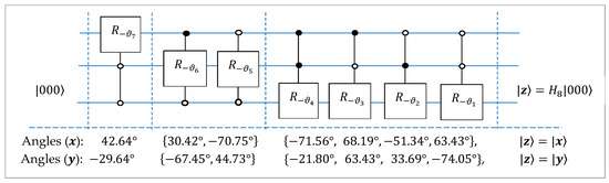
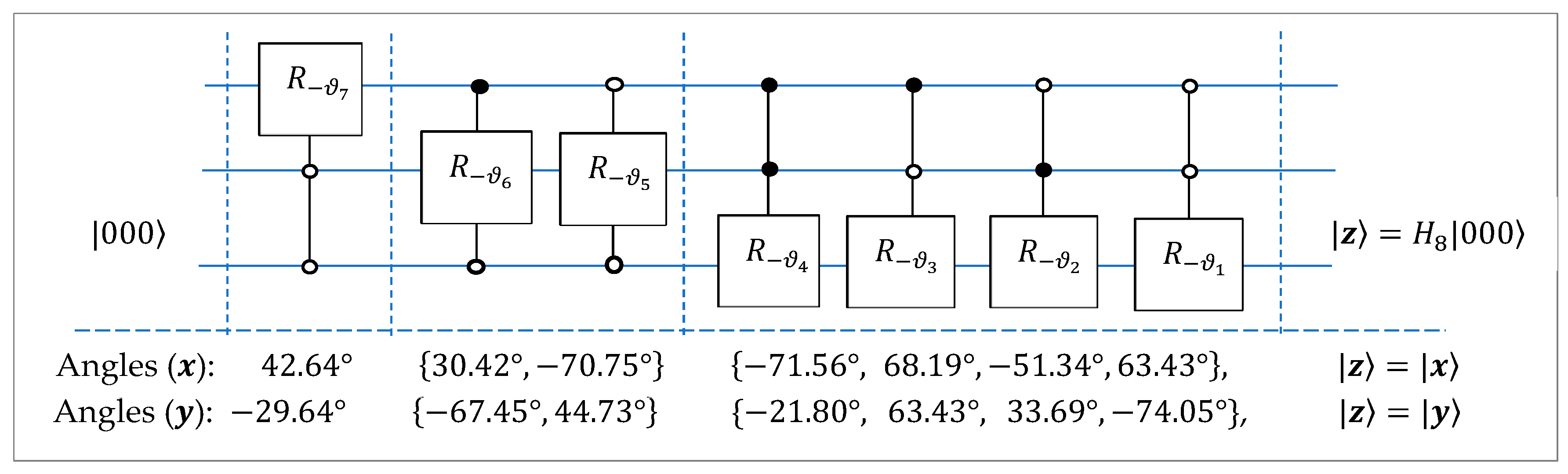
The quantum circuit for the inverse 3-qubit QsiHT with the roadmap in Figure 15 is shown in Figure 16. This circuit can be used for the preparation of any 3-qubit superposition , by using the corresponding seven angles, . To prepare the 3-qubit superpositions and , we need two separate circuits, that is, one circuit with angles of rotations of for and another circuit with the angles of for Each such circuit requires only seven 2-qubit controlled rotation gates.
Figure 16.
The circuits for the initiation of the 3-qubit state .
5. Circuit Simulation and Analysis Using IBM’s Qiskit Framework
The quantum circuits implementing the Q2siHT transform were simulated and analyzed using IBM’s open-source Qiskit framework [29]. Qiskit is a framework for designing, optimizing, and executing quantum circuits. It includes realistic backends, various simulators, and visualization tools that enable direct comparison between ideal and noisy circuit executions within the same computational framework [30].
Two types of simulations were performed to evaluate the accuracy and noise sensitivity of the proposed circuits. The first simulation was conducted under noise-free (ideal) conditions to obtain the theoretical probability distributions of the output quantum states. The second simulation incorporated a noise model using Qiskit’s GenericBackendV2, where the default noise parameters were applied. These parameters represent typical operational characteristics of IBM Quantum hardware such as gate readout errors and finite qubit coherence times. This allows for an approximate estimation of circuit behaviour under realistic experimental conditions [31].
To quantify the deviation between the simulated and theoretical results, the Root Mean Square Error (RMSE) was used as a performance metric, mathematically defined as
where and denote the simulated and theoretical probabilities of the -th quantum state, and is the total number of possible output states. As shown in Equation (70), the RMSE provides a quantitative measure of the average deviation between the simulation results and theoretical expectations. A smaller RMSE indicates closer arrangement between simulated and theoretical distributions, which demonstrates the accuracy of the proposed Q2siHT-based quantum superposition preparation circuits under both ideal and noisy simulation environments.
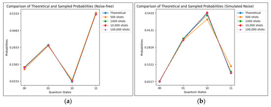
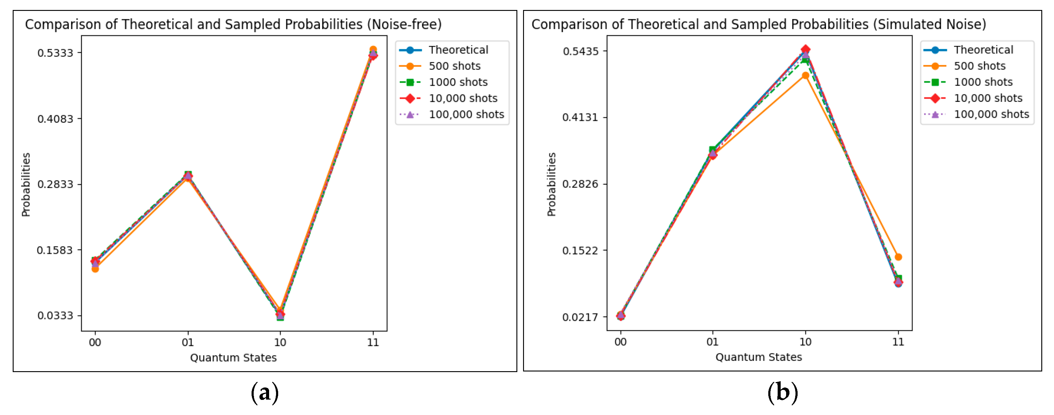
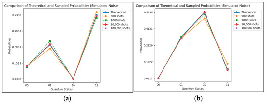
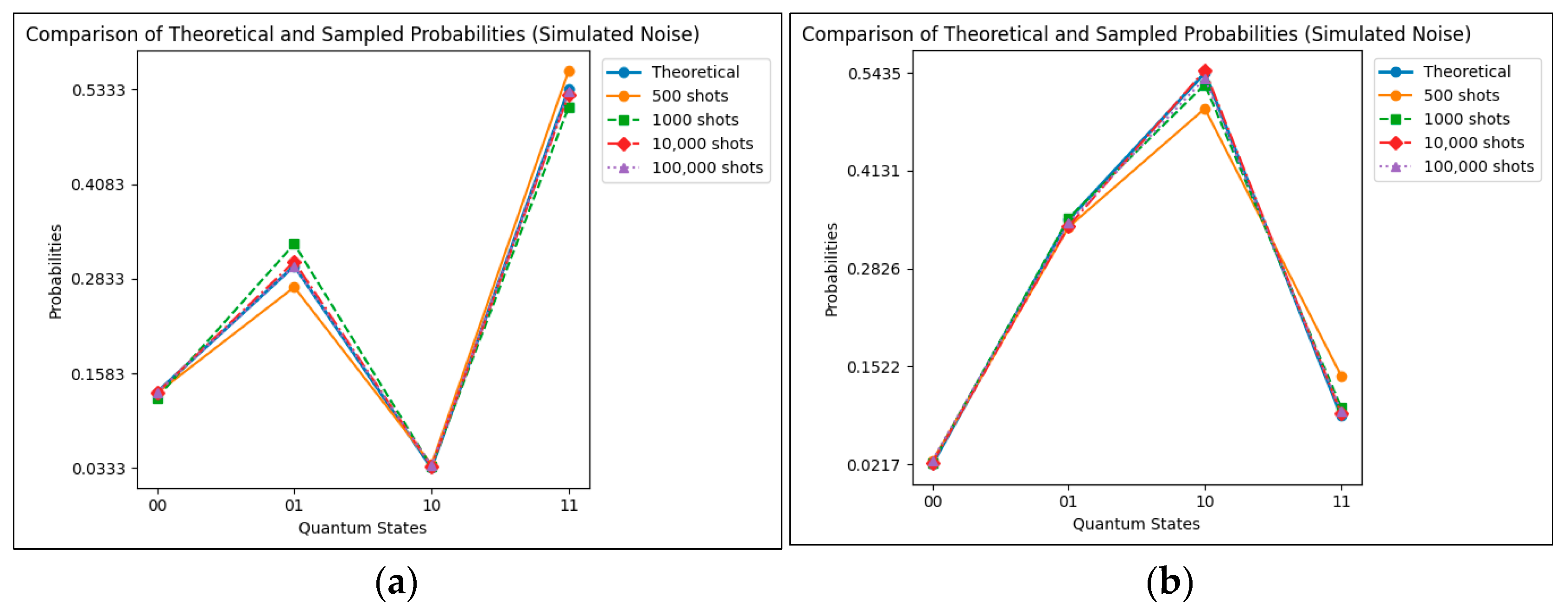
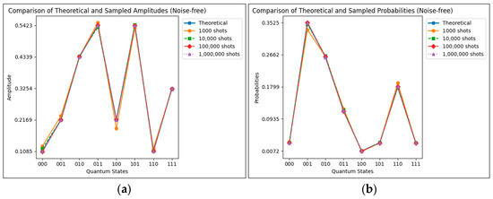
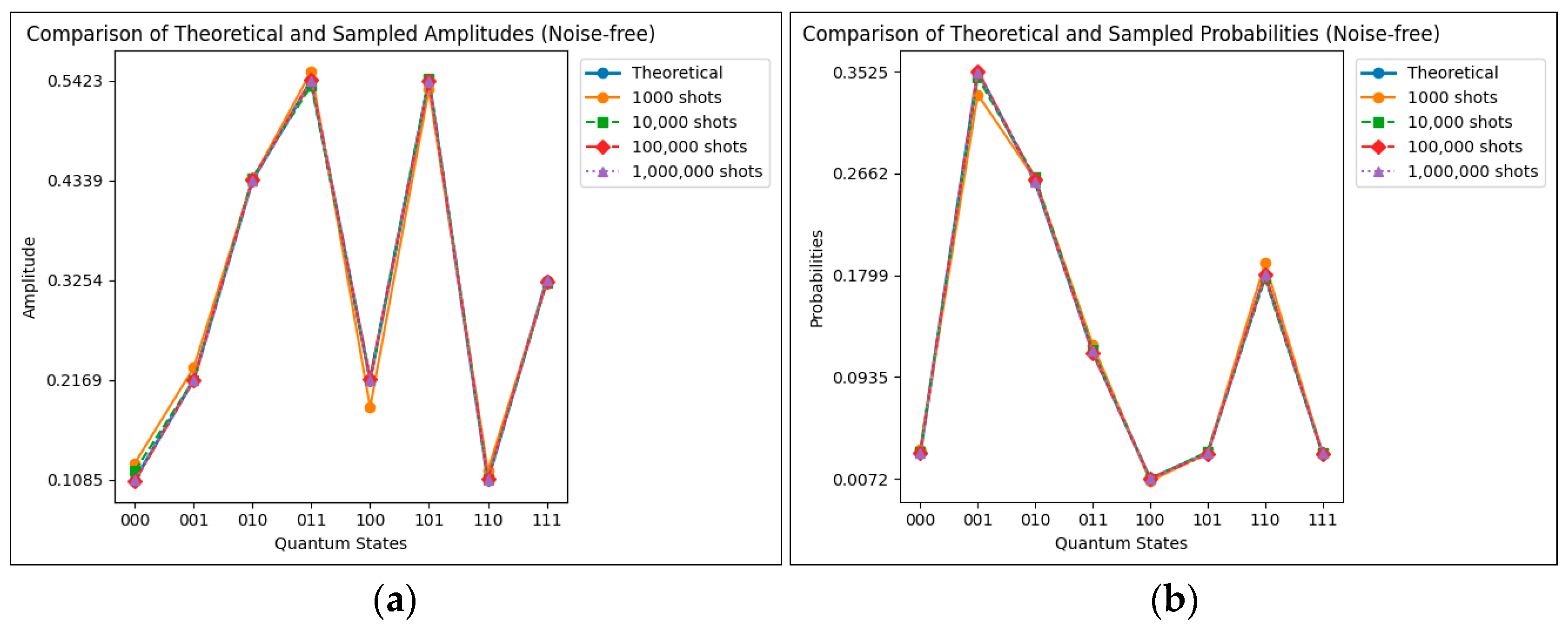
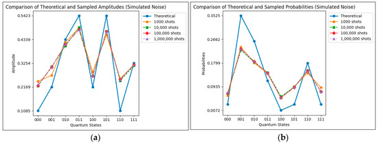
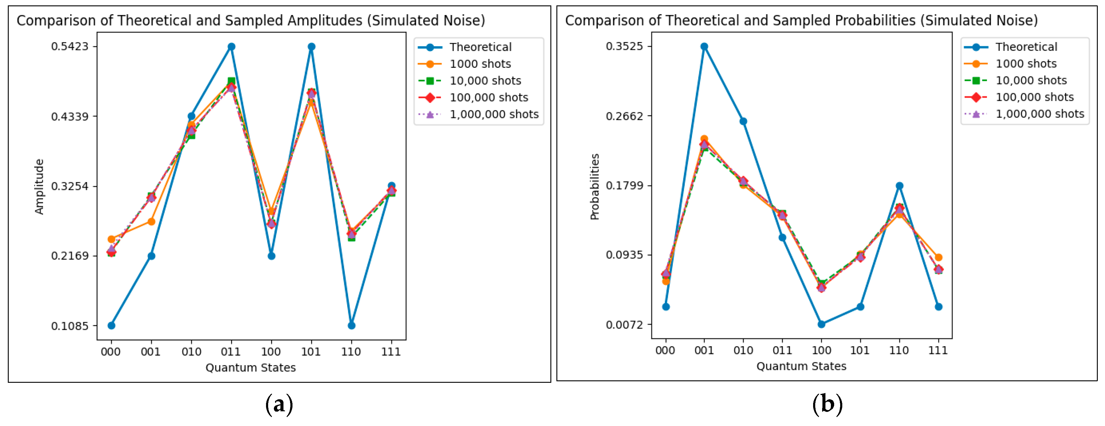
The RMSE values and corresponding error distributions were obtained for the inverse Q2siHT fast path circuits of both the 2-qubit and 3-qubit systems. For each configuration, the results were generated under noise-free and noisy conditions. The numerical RMSE results are summarized in Table 7, Table 8, Table 9 and Table 10, and their corresponding visual representations of the error distributions are shown in Figure 17, Figure 18, Figure 19 and Figure 20.
Table 7.
RMSE values for the inverse 2-qubit Q2siHT fast path circuit under noise-free simulation for and .
Table 8.
RMSE values for the inverse 2-qubit Q2siHT fast path circuit under noisy simulation (GenericBackendV2) for and .
Table 9.
RMSE values for the inverse 3-qubit Q2siHT fast path circuit under noise-free simulation for and .
Table 10.
RMSE values for the inverse 3-qubit Q2siHT fast path circuit under noisy simulation (GenericBackendV2) for and .
Figure 17.
RMSE distribution for the inverse 2-qubit Q2siHT fast path circuit for (a) and (b) (noise-free case).
Figure 18.
RMSE distribution for the inverse 2-qubit Q2siHT fast path circuit for (a) and (b) (with noise).
Figure 19.
RMSE distribution for the inverse 3-qubit Q2siHT fast path circuit for (a) and (b) (noise-free case).
Figure 20.
RMSE distribution for the inverse 3-qubit Q2siHT fast path circuit for (a) and (b) (with noise).
It should be noted that the numerical examples presented in this work are used solely to demonstrate the operation and implementation of the proposed method and do not represent any specific physical or practical quantum systems. Furthermore, the described Q2siHT-based approach requires solving the decision equations to determine the rotation parameters. In this work, a classical computer is used to solve such equations.
When implementing these circuits through IBM’s Qiskit framework, the single and controlled qubit rotation gates are represented in IEEE-754 double-precision format, which provides around 15–16 significant digits of numerical accuracy. In our simulations, all rotation parameters were maintained with a precision of 0.01°. It is important to note that the Qiskit transpiler may omit extremely small rotations (less than 10−8 rad) during optimization, so to prevent such removals, each computed rotation was preserved with at least four significant digits in degrees.
6. Conclusions
In this work, we present, for the first time, the discrete two signal-induced heap transformation (D2sHT). This transformation is generated by two given vectors or superpositions. The quantum analogue of this transform, namely the Q2siHT, is described, and the quantum circuits of its implementation are considered. We propose a new method of the preparation of the two states with 3D rotations by using the concept of the D2siHT. The amplitudes of quantum superpositions are considered real. Examples for 2- and 3-qubit superpositions are described with quantum circuits. It is also shown that this transformation can be implemented by using different paths of processing generators and input signals. Regarding the examples with the 3-qubit Q2siHT with strong and fast paths, the importance of this characteristic for the transformation is shown. Simulations using the Qiskit framework using the inverse Q2siHT fast path state preparation approach demonstrate that the Q2siHT is reliable and efficient for quantum state preparation. The low RMSE values in the noise-free simulations verify the theoretical precision of the proposed circuits, while the moderate error observed under noisy conditions demonstrates convergence and resilience to common sources of quantum decoherence. These results highlight their practical feasibility and application in future implementations on real quantum hardware. Although this work focuses primarily on the simultaneous preparation of two states in the same quantum circuit, the method of preparing individual states is demonstrated as well in Figure 15 and Figure 16. This is performed to highlight that either quantum algorithm can be easily implemented for various design constraints where circuit fidelity may need to be minimized but certain gate parameters can be changed. In the case where only one gate parameter can be changed, the Q2siHT is able to “multiplex”, or switch between, two quantum superpositions by only changing the angle of one rotation gate.
The problem of two state preparation with complex amplitudes can also be considered and solved by the complex Q2siHT with three decision equations and complex rotation operations [25,32]. This case requires careful study. We need to initiate two superpositions x and y. The real basic transformations defined in Equation (22) are defined by the angles which are calculated from three 3D vectors, as shown in Equation (24). We need to solve angular Equation (23) when all triplets in Equation (26) are complex. We do not yet have a simple analytical solution to this problem. One possible way to resolve this is to remove the phases from the generators first
and then initiate the superpositions and by the Q2siHTs described above. After that, we need to add the phase gates in the described circuits to restore the original superpositions and . We will consider the solution of this problem in our future work.
Finally, although the Q2siHT is presented in an abstract algorithmic framework, its implementation in experimental quantum platforms with coherent control and multi-qubit superpositions may be achieved. For instance, cavity quantum electrodynamics systems provide the precise control of atom photon interactions and have been used to realize complex superpositions of atomic states [33]. Similarly, superconducting qubits and trapped ions enable scalable and high-fidelity multi-qubit operations that could potentially serve as realistic environments for testing the proposed Q2siHT circuits. In these experimental platforms, the controlled rotations and operations required by the Q2siHT could be directly available as gate primitives, which would allow the proposed circuits to be benchmarked using current hardware to evaluate their resilience to noise, decoherence, and gate depth constraints [34].
Author Contributions
Conceptualization, A.M.G.; methodology, A.M.G.; software, A.M.G. and A.A.G.; validation, A.M.G. and A.A.G.; formal analysis, A.M.G. and A.A.G.; investigation, A.M.G.; resources, A.M.G.; data curation, A.M.G. and A.A.G.; writing—original draft preparation, A.M.G.; writing—review and editing, A.M.G. and A.A.G.; visualization, A.M.G. and A.A.G.; supervision, A.M.G.; project administration, A.M.G.; funding acquisition, A.M.G. All authors have read and agreed to the published version of the manuscript.
Funding
This research received no external funding.
Institutional Review Board Statement
Not applicable.
Informed Consent Statement
Not applicable.
Data Availability Statement
The original contributions presented in this study are included in the article. Further inquiries can be directed to the corresponding author.
Conflicts of Interest
The authors declare no conflicts of interest.
Abbreviations
The following abbreviations are used in this manuscript:
| DsiHT | Discrete signal-induced heap transform |
| D2siHT | Discrete two signal-induced heap transform |
| Q2siHT | Quantum two signal-induced heap transform |
| BP | Bit plane |
References
- Deutsch, D. Quantum computational networks. Proc. R. Soc. Lond. A Math. Phys. Sci. 1989, 425, 73–90. [Google Scholar]
- Deutsch, D.; Barenco, A.; Ekert, A. Universality in quantum computation. Proc. R. Soc. Lond. A Math. Phys. Sci. 1995, 449, 669–677. [Google Scholar]
- Barenco, A.; Bennett, C.H.; Cleve, R.; DiVincenzo, D.P.; Margolus, N.; Shor, P.; Sleator, T.; Smolin, J.A.; Weinfurter, H. Elementary gates for quantum computation. Phys. Rev. A 1995, 52, 3457. [Google Scholar] [CrossRef] [Scilit] [PubMed]
- Knill, E. Approximation by Quantum Circuits; LANL Rep. LAUR-95-2225; Los Alamos National Laboratory: Los Alamos, NM, USA, 1995. [Google Scholar]
- Long, G.-L.; Sun, Y. Efficient scheme for initializing a quantum register with an arbitrary superposed state. Phys. Rev. A 2001, 64, 014303. [Google Scholar] [CrossRef] [Scilit]
- Shende, V.V.; Markov, I.L. Quantum circuits for incompletely specified two-qubit operators. Quantum Inf. Comput. 2005, 5, 49–58. [Google Scholar] [CrossRef] [Scilit]
- Bärtschi, A.; Eidenbenz, S. Deterministic preparation of Dicke states. In International Symposium on Fundamentals of Computation Theory; Springer: Cham, Switzerland, 2019. [Google Scholar]
- Plesch, M.; Brukner, C. Quantum state preparation with universal gate decompositions. arXiv 2010, arXiv:1003.5760v2. [Google Scholar] [CrossRef] [Scilit]
- Gleinig, N.; Hoefler, T. An efficient algorithm for sparse quantum state preparation. In Proceedings of the 58th ACM/IEEE Design Automation Conference, San Francisco, CA, USA, 5–9 December 2021; IEEE: New York, NY, USA, 2021. [Google Scholar]
- de Veras, T.M.; da Silva, L.D.; da Silva, A.J. Double sparse quantum state preparation. Quantum Inf. Process. 2002, 21, 204. [Google Scholar] [CrossRef] [Scilit]
- Volya, D.; Mishra, P. State preparation on quantum computers via quantum steering. arXiv 2023, arXiv:2302.13518v3. [Google Scholar] [CrossRef] [Scilit]
- Householder, A.S. Unitary Triangulation of a Nonsymmetric Matrix. J. ACM 1958, 5, 339–342. [Google Scholar] [CrossRef] [Scilit]
- Rutishause, H. Simultaneous Iteration Method for Symmetric Matrices. In Linear Algebra. Handbook for Automatic Computation; Bauer, F.L., Ed.; Springer: Berlin/Heidelberg, Germany, 2017. [Google Scholar]
- Golub, G.H.; Van Loan, C.F. Matrix Computations, 3rd ed.; Johns Hopkins Press: Baltimore, ML, USA, 1996. [Google Scholar]
- Bindel, D.; Demmel, J.; Kahan, W.; Marques, O. On Computing Givens Rotations Reliably and Efficiently; LAPACK Working Note 148; UT-CS-00-449; University of Tennessee: Knoxville, TN, USA, 2001. [Google Scholar]
- Demmel, J.; Grigori, L.; Hoemmen, M.; Langou, J. Communication-optimal parallel and sequential QR and LU factorizations. SIAM J. Sci. Comp. 2012, 34, 206–239. [Google Scholar] [CrossRef] [Scilit]
- Wang, H.; Bochen, T.D.; Cong, J. Quantum state preparation circuit optimization exploiting don’t cares. arXiv 2024, arXiv:2409.01418. [Google Scholar]
- Pinto, D.F.; Friedrich, L.; Maziero, J. Preparing general mixed quantum states on quantum computers. arXiv 2024, arXiv:2402.04212. [Google Scholar] [CrossRef] [Scilit]
- Zhang, X.M.; Li, T.; Yuan, X. Quantum state preparation with optimal circuit depth: Implementations and applications. Phys. Rev. Lett. 2022, 129, 230504. [Google Scholar] [CrossRef] [Scilit] [PubMed]
- Vartiainen, J.J.; Möttönen, M.; Salomaa, M.M. Efficient decomposition of quantum gates. Phys. Rev. Lett. 2004, 92, 177902. [Google Scholar] [CrossRef] [Scilit] [PubMed]
- Möttönen, M.; Vartiainen, J.J.; Bergholm, V.; Salomaa, M.M. Quantum circuits for general multiqubit gates. Phys. Rev. Lett. 2004, 93, 130502. [Google Scholar] [CrossRef] [Scilit]
- Bergholm, V.; Vartiainen, J.J.; Möttönen, M.; Salomaa, M.M. Quantum circuits with uniformly controlled one-qubit gates. arXiv 2004, arXiv:quant-ph/0410066v2. [Google Scholar] [CrossRef] [Scilit]
- Shende, V.V.; Bullock, S.S.; Markov, I.L. Synthesis of quantum-logic circuits. IEEE Trans. Comput.-Aided Des. Integr. Circuits Syst. 2006, 25, 1000–1010. [Google Scholar] [CrossRef] [Scilit]
- Grigoryan, A.M.; Gomez, A.; Agaian, S.S. A Novel approach to state-to-state transformation in quantum computing. Information 2025, 16, 689. [Google Scholar] [CrossRef] [Scilit]
- Grigoryan, A.M. New permutation-free quantum circuits for implementing 3- and 4-qubit unitary operations. Information 2025, 16, 621. [Google Scholar] [CrossRef] [Scilit]
- Grigoryan, A.M.; Grigoryan, M.M. Brief Notes in Advanced DSP: Fourier Analysis with MATLAB; CRC Press: Boca Raton, FL, USA; Taylor, and Francis Group: Abingdon, UK, 2009. [Google Scholar]
- Nielsen, M.A.; Chuang, I.L. Quantum Computation and Quantum Information; Cambridge University Press: Cambridge, UK, 2000. [Google Scholar]
- Rieffel, E.G.; Polak, W.H. Quantum Computing: A Gentle Introduction; The MIT Press: Cambridge, MA, USA, 2011. [Google Scholar]
- Qiskit Development Team. Qiskit: An Open-Source Framework for Quantum Computing, Version 1.3.2. Computer Software. IBM Quantum: Poughkeepsie, NY, USA, 2019.
- Mykhailova, M. Quantum Programming in Depth Solving problems with Q# and Qiskit; Manning: Shelt Island, NY, USA, 2025. [Google Scholar]
- IBM Quantum. Exact and Noisy Simulation with Qiskit Aer Primitives. IBM Quantum Documentation—Guides, 2024–2025. Available online: https://quantum.cloud.ibm.com/docs/guides/simulate-with-qiskit-aer (accessed on 1 November 2025).
- Grigoryan, A.M. Effective methods of QR-decompositions of square complex matrices by fast discrete signal-induced heaptransforms. Adv. Linear Algebra Matrix Theory (ALAMT) 2023, 12, 87–110. [Google Scholar] [CrossRef]
- Haroche, S.; Raimond, J.-M. Exploring the Quantum: Atoms, Cavities, and Photons; Oxford University Press: Oxford, UK, 2006; ISBN 0-19-850914-6. [Google Scholar]
- Häffner, H.; Roos, C.F.; Blatt, R. Quantum Computing with Trapped Ions. Phys. Rep. 2008, 469, 155–203. [Google Scholar] [CrossRef] [Scilit]

Disclaimer/Publisher’s Note: The statements, opinions and data contained in all publications are solely those of the individual author(s) and contributor(s) and not of MDPI and/or the editor(s). MDPI and/or the editor(s) disclaim responsibility for any injury to people or property resulting from any ideas, methods, instructions or products referred to in the content. |
© 2025 by the authors. Licensee MDPI, Basel, Switzerland. This article is an open access article distributed under the terms and conditions of the Creative Commons Attribution (CC BY) license (https://creativecommons.org/licenses/by/4.0/).