


Abstract
This study presents a structural integrity evaluation of a 5000 m3 IMO Type C independent tank designed for storing liquefied carbon dioxide (LCO2) at −35 °C and 15 barg, based on the IMO IGC Code and Korean Register (KR) rules. A finite element model was developed to assess structural responses under representative load cases considering thermal contraction, internal pressure, and ship-induced accelerations. The results show that structural design is predominantly governed by the internal pressure associated with liquefaction conditions and boil-off gas (BOG) accumulation, rather than the minimum design pressure specified by classification rules or liquid head pressure. As a result, the required tank thickness approaches the upper practical limit (approximately 50 mm), leading to inherently sufficient buckling resistance without additional design constraints. These findings indicate that, under medium-pressure LCO2 storage conditions, Type C tank design is primarily pressure-driven, and structural stability can be effectively ensured through thickness design. The study provides practical insights into governing design factors for rule-based tank design and highlights key considerations for LCO2 storage applications.
1. Introduction
With the growing global emphasis on decarbonization and climate neutrality, carbon capture, utilization, and storage (CCUS) technologies have attracted considerable attention as key enablers for reducing CO2 emissions across industrial sectors [1,2,3]. Among the components of the CCUS value chain, marine transport of liquefied carbon dioxide (LCO2) has emerged as a practical and scalable solution for connecting inland CO2 emission sources to offshore storage or utilization sites, particularly where pipeline infrastructure is not feasible [4,5,6].
Carbon dioxide can be liquefied either under high-pressure ambient-temperature conditions or low-temperature moderate-pressure conditions. According to the CO2 phase diagram, liquefaction occurs at approximately 55–65 bar near ambient temperature or at 6–15 bar from −50 °C to −20 °C [7,8]. For marine transport, the latter condition is preferred due to lower pressure requirements, enhanced safety, and compatibility with pressure vessel design [4,9]. Consequently, low-temperature moderate-pressure storage has been widely adopted in ship-based LCO2 transport systems [10].
Under these conditions, independent IMO Type C tanks—defined as self-supporting pressure vessels in the IMO International Gas Carrier (IGC) Code [11]—are considered suitable for pressurized cryogenic storage, unlike membrane-type LNG tanks requiring secondary containment. Typically designed in cylindrical or bi-lobe configurations, Type C tanks follow pressure vessel principles with additional marine safety margins according to Korean Register (KR) rules [12] and ABS guidance [13].
Although structural behavior of Type C tanks has been extensively studied for LPG and LNG applications [14,15,16], relatively limited research addresses LCO2 storage systems under CCUS conditions.
The structural design procedure for IMO Type C tanks follows a sequential framework rooted in three interconnected elements. The starting point is fracture mechanics-based fatigue crack propagation criteria embedded in the IGC Code, which define the minimum design vapor pressure: the rule formulation ensures that the primary membrane stress remains sufficiently low that an initial surface flaw will not propagate beyond half the shell thickness over the vessel’s service life [11]. This fracture mechanics basis directly underpins the rule-based thickness design, in which the minimum shell thickness is determined from pressure vessel formulations prescribed by classification society rules (IGC Code, KR, ABS) using allowable stress criteria derived accordingly [11,12,13]. Once the shell thickness is established, FEA-based structural verification is performed to confirm compliance with stress limits under multiple combined load cases including ship-induced accelerations, heeling, thermal contraction, and internal pressure [15].
However, a practical complication arises in determining the design vapor pressure. The IGC Code minimum design vapor pressure is derived from fatigue crack propagation considerations and does not directly reflect the actual thermodynamic vapor pressure of the stored cargo. In practice, the actual internal pressure of a Type C tank is governed by the liquefaction conditions of the cargo and BOG accumulation during operation, which may differ substantially from the rule-based minimum [17]. When the actual thermodynamic pressure governs, the required shell thickness is determined by operational conditions rather than the rule minimum, leading to pressure-driven designs in which shell thickness approaches practical fabrication limits and secondary load effects become relatively less critical. For LCO2-specific applications, this pressure-driven design regime and its structural implications have not been systematically addressed. The present study addresses this gap by integrating rule-based pressure determination, FEA-based structural verification, and an assessment of governing design factors within a single coherent framework for LCO2 marine storage.
Existing studies primarily focus on rule-based safety verification and vapor pressure optimization [13,17], while governing design factors under combined loading—particularly the relative contributions of internal pressure, liquid head pressure, and thermal effects—remain insufficiently clarified for LCO2 service. In practical scenarios, internal pressure from liquefaction conditions and boil-off gas (BOG) accumulation often exceeds classification society minimum design pressures, leading to thickness-driven designs where shell thickness approaches practical limits and buckling becomes less critical [17]. However, these pressure-driven design implications have not been systematically addressed. This study evaluates the structural integrity of a 5000 m3 IMO Type C tank for LCO2 marine storage based on the IMO IGC Code [11] and Korean Register (KR) rules [12]. Finite element analysis considers thermal contraction, internal pressure, gravitational loads, ship accelerations, and external pressure. Beyond safety verification, this work identifies dominant design factors under realistic operating conditions. The findings elucidate pressure-driven characteristics of Type C tanks and clarify load component contributions, enhancing understanding of rule-based design and providing guidance for efficient LCO2 storage system development.
2. Design Basis and Tank Configuration
The present study considers a 5000 m3 independent IMO Type C tank designed for the storage and transport of liquefied carbon dioxide (LCO2) under cryogenic and pressurized conditions. The selected storage condition is −35 °C and 15 barg, which represents a typical low-temperature and moderate-pressure regime for marine LCO2 transport, consistent with the storage conditions widely reported in the literature for ship-based LCO2 carriers [4,8,17]. Under these conditions, the internal pressure is primarily governed by thermodynamic equilibrium and boil-off gas (BOG) accumulation.
The structural evaluation includes strength assessment under combined loading conditions, buckling analysis, and thermal stress analysis. The design framework follows the general requirements for pressure vessels applied to marine cargo containment systems.
Liquefied gas carriers are classified according to their cargo containment systems, including integral, membrane, semi-membrane, and independent tanks. Independent tanks are further categorized into Types A, B, or C depending on their design philosophy and allowable leakage criteria. Among these, Type C tanks are designed as pressure vessels with the assumption of no leakage throughout their service life and are therefore capable of sustaining internal pressure without secondary containment.
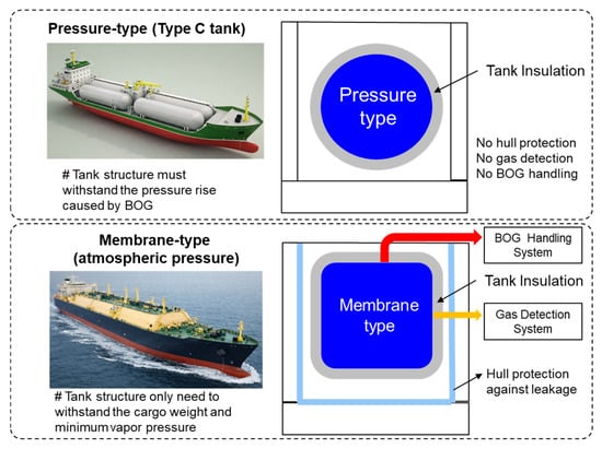
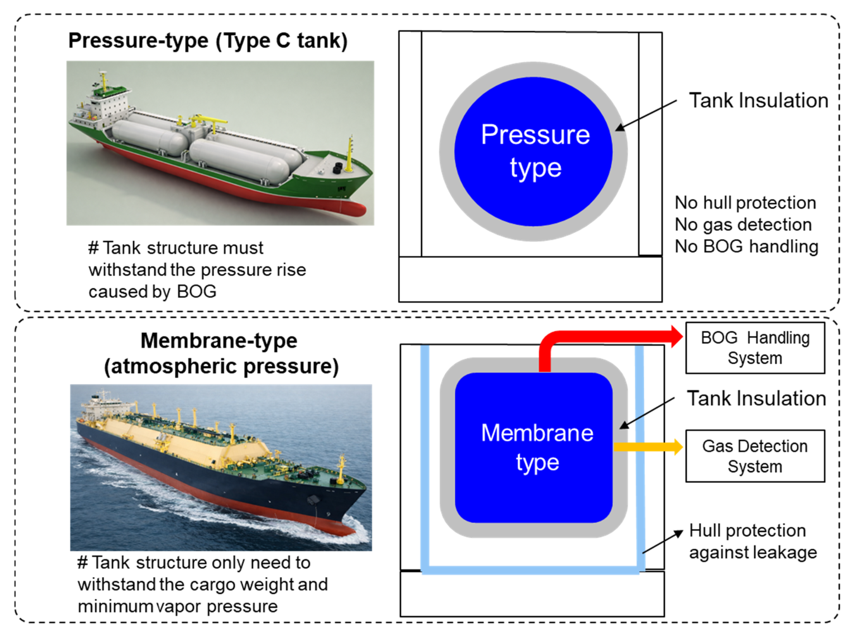
As illustrated in Figure 1, pressure-type containment systems (Type C tanks) operate as closed systems, in which internal pressure increases due to BOG accumulation. In contrast, membrane-type containment systems operate near atmospheric pressure by continuously managing BOG through gas handling systems and require additional safety measures such as gas detection for leakage monitoring. This fundamental difference leads to distinct design approaches, with Type C tanks being more suitable for pressurized storage applications such as LCO2 transport.
Figure 1.
Comparison between pressure-type (Type C) and membrane-type containment systems.
Carbon dioxide can be stored either in a low-temperature moderate-pressure region or in a high-pressure near-ambient-temperature region. In marine applications, the high-pressure option is generally avoided due to the excessive structural thickness required. Therefore, cryogenic pressurized storage is adopted as a balanced design approach in terms of safety, storage efficiency, and structural feasibility. The selected tank has a cylindrical geometry with hemispherical end caps and a total internal volume of 5000 m3. The inner diameter is 13.4 m and the total length is 40.0 m, including the end caps. This capacity represents the upper practical range of Type C tanks, where structural constraints such as shell thickness become critical. Two identical tanks are arranged longitudinally within the hull of a 10,000 m3-class carrier. The principal dimensions of the vessel are summarized in Table 1.
Table 1.
Estimated principal particulars of the carrier.
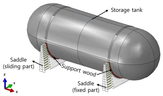
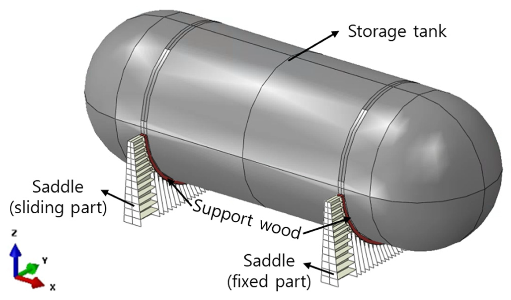
The cargo tank system consists of pressure vessels, saddle support structures, and support wood blocks. The detailed configuration of the system is illustrated in Figure 2.
Figure 2.
Configuration of the Type C tank system showing fixed and sliding saddle supports.
To accommodate thermal contraction under cryogenic conditions, one saddle is fixed while the other allows longitudinal sliding. This arrangement enables thermal expansion and contraction of the tank without inducing excessive constraint forces. The saddle supports transfer loads from the tank to the hull structure through support wood blocks. The support wood blocks are fabricated from a high-density cross-ply laminated compressed wood (product grade YongWooden 7502S/2005S, YONG WOO., LTD., Yangsan-si, Gyeongnam, Republic of Korea), produced by a cross-ply hot-press compression process. This yields a density of 1350 kg/m3 and a compressive strength of 250 MPa perpendicular to grain (conservative lower bound of the manufacturer-reported range of 250–270 MPa, cryogenic condition) with an application temperature range of −196 to 100 °C suitable for cryogenic service. This material class has been used as standard support wood in cryogenic LPG and LCO2 IMO Type C tank installations and holds type approval from DNV-GL, Lloyd’s Register, Korean Register, ABS, and Bureau Veritas. The tank is fabricated from low-temperature carbon–manganese steel (LT-FH70), while the saddle structures are made of marine structural steel (DH36). Polyurethane foam (PUF) insulation with a thickness of 200 mm is applied for thermal protection but is excluded from structural analysis due to its negligible stiffness contribution. Table 2 shows the summary of tank system components.
Table 2.
Summary of tank system components.
Mechanical properties of the structural materials are presented in Table 3. The allowable membrane stress is defined as:
where is the yield strength, is the ultimate tensile strength, and and are safety factors. For carbon–manganese steels, values of and are adopted.
Table 3.
Mechanical properties of main structural materials.
Based on these criteria, the allowable stress for LT-FH70 under combined membrane and bending conditions is 385 MPa, while that for DH36 is 245 MPa. For the support wood, a conservative compressive stress limit of 80 MPa is applied.
3. Design Pressure and Structural Analysis Methodology
3.1. Design Pressure Determination and Thickness Design
The design pressure for IMO Type C tanks is defined as the sum of the design vapor pressure and the maximum liquid head pressure in accordance with the IMO IGC Code [4]. According to the IGC Code, the minimum design vapor pressure is determined based on fatigue crack propagation considerations rather than thermodynamic storage conditions. The rule formulation is expressed as:
where is a coefficient related to the allowable dynamic membrane stress, is a characteristic tank dimension, and is the relative density of the cargo. For the present configuration, the minimum design vapor pressure calculated from the rule is approximately 10.3 barg.
However, for LCO2 storage, the vapor pressure is primarily governed by thermodynamic conditions. In this study, the initial storage condition is set to 14 barg at −35 °C. To account for pressure increase due to boil-off gas (BOG) accumulation during operation, the pressure rise is estimated based on thermodynamic analysis following the methodology presented in Ref. [17]. Specifically, the pressure increase over time is evaluated by considering heat ingress through the insulation system and subsequent vapor generation. The heat transfer is modeled using a one-dimensional conduction approach based on Fourier’s law, considering the insulation thickness (200 mm polyurethane foam) and thermal properties. The initial filling condition assumes 90% liquid volume to allow vapor space for pressure buildup. The following thermal parameters were adopted: PUF insulation thermal conductivity k = 0.02 W/m·K; support wood thermal conductivity k = 0.227 W/m·K (perpendicular to grain, cross-section 500 mm × 300 mm per saddle); ambient temperature T_amb = 20 °C; inner tank surface temperature T_inner = −35 °C (ΔT = 55 °C); initial liquid fill ratio 90%. Convective resistance at the outer surface was conservatively neglected. Heat ingress through the PUF shell and support wood heat bridges was computed separately and summed to obtain the total heat ingress rate. The total heat ingress rate through the insulation system is expressed as: = _PUF + _wood = (k_PUF × A_PUF/t_PUF) × ΔT + (k_wood × A_wood/t_wood) × ΔT, where A_PUF is the outer surface area covered by PUF, t_PUF = 0.2 m, A_wood is the total cross-sectional area of support wood heat bridges, t_wood = 0.3 m, and ΔT = 55 °C. The energy balance for the closed two-phase system is ΔU = Q_in, with m_total = m_liquid + m_vapor and V_total = V_liquid + V_vapor enforced at each time step. The updated thermodynamic state is determined using the REFPROP database. Using REFPROP thermodynamic properties, the relationship between temperature and pressure under saturated conditions is established. Based on the estimated heat ingress and a 30-day holding time, the internal pressure is found to increase by approximately 1 bar. Accordingly, the design vapor pressure is set to 15 barg. A comprehensive parametric study evaluating the sensitivity of the BOG-induced pressure rise to liquefaction temperature, tank volume, L/D ratio, ambient temperature, holding time, and insulation thickness is reported in Ref. [17], confirming that the 1 bar pressure rise estimate is conservative and robust across the practical range of operating conditions for medium-to-large LCO2 storage tanks. The thermodynamic model adopted in this study assumes quasi-static saturated equilibrium between the liquid and vapor phases. While non-equilibrium transient behavior may arise during rapid operations such as filling or venting, these phenomena are short-lived and do not govern the sustained pressure accumulation over the 30-day holding period considered here. The saturated-state assumption represents an upper bound for the equilibrium vapor pressure at any given temperature and is therefore conservative for structural design purposes. This approach is consistent with standard practice in rule-based design of IMO Type C tanks, and its applicability across a broad range of storage conditions is validated in Ref. [17].
The maximum liquid head pressure is calculated considering both static and dynamic effects due to ship motion. According to IGC Code Section 4.28.2 and KR rule guidance, the dynamic liquid pressure is given by:
where is the non-dimensional design acceleration, is the vertical distance from the free surface, and is the cargo density (1100 kg/m3 at −35 °C).
Using the design accelerations (0.87 g vertical, 0.70 g transverse, 0.25 g longitudinal), the maximum dynamic liquid head pressure is estimated as approximately 0.29 MPa (≈2.9 barg). Accordingly, the design pressure is determined as . For conservative structural design, a value of 18 barg is adopted. For conservative structural design, a value of 18 barg is adopted. This clearly indicates that the design of Type C tanks for LCO2 is primarily governed by thermodynamic pressure conditions rather than rule-based minimum requirements. To summarize the design pressure derivation: the initial storage condition of 14 barg at −35 °C already exceeds the rule-based minimum vapor pressure of 10.3 barg; the addition of approximately 1 bar pressure rise due to BOG accumulation over a 30-day holding period yields a design vapor pressure (MARVS) of 15 barg; and the maximum dynamic liquid head pressure of approximately 2.9 barg, calculated from the ship motion accelerations per IGC Code Section 4.28.2, brings the total design pressure to 15 + 2.9 ≈ 18 barg, adopted conservatively as 18 barg for structural design.
The required shell thickness is determined based on the internal design pressure, tank geometry, allowable stress, and corrosion allowance. According to KR rules, the minimum required thickness for a cylindrical shell is given by:
where is the design pressure, is the internal radius, is the allowable primary membrane stress, is the weld joint efficiency (assumed as 1.0), and is the corrosion allowance.
Using the design parameters: , , , the minimum required shell thickness is calculated as approximately 48.2 mm. Accordingly, a nominal thickness of 50 mm is adopted for the cylindrical section and 25 mm for the end caps, as summarized in Table 4.
Table 4.
Final shell thickness design.
3.2. Finite Element Analysis (FEA) Methodology
Finite element analysis (FEA) was performed to evaluate the structural response of the Type C tank under the design pressure and loading conditions determined in Section 3.1. The objective of the analysis is to verify structural integrity and to identify dominant stress components under realistic operating conditions. The finite element model was developed using ABAQUS/Standard. The storage tank and saddle structures were modeled using four-node reduced-integration shell elements (S4R) to efficiently capture membrane and bending behavior of the cylindrical shell and end caps. The support wood was modeled using eight-node solid elements (C3D8R) to account for local compressive load transfer between the tank and the saddle supports. The interaction between the storage tank, support wood, and saddle structures was defined using surface-to-surface contact with a penalty formulation, allowing realistic simulation of load transfer and local deformation at the interfaces.
The boundary conditions were defined based on the actual support configuration shown in Figure 2. One saddle was fully constrained (fixed saddle), while the other was allowed to slide in the longitudinal direction (sliding saddle) to accommodate thermal contraction of the tank under cryogenic conditions. This support arrangement enables realistic representation of constraint effects and prevents artificial restraint of thermal deformation. At the fixed saddle, the interface between the storage tank and the support wood was constrained using tie conditions to prevent relative motion. At the sliding saddle, no tie constraint was applied at the tank–wood interface; instead, a frictionless surface-to-surface contact interaction was defined at this interface, allowing free longitudinal translation of the tank (x-direction) while maintaining vertical load transfer through the contact normal force. Tie constraints were retained at the wood–saddle interface at both saddles to prevent separation of the support wood from the saddle structure. This configuration replicates the physical sliding mechanism, in which thermal contraction of the tank is accommodated by free longitudinal displacement at the sliding saddle without generating additional constraint forces in that direction. The bases of the saddle structures were assumed to be rigidly connected to the hull, and all translational degrees of freedom were constrained.
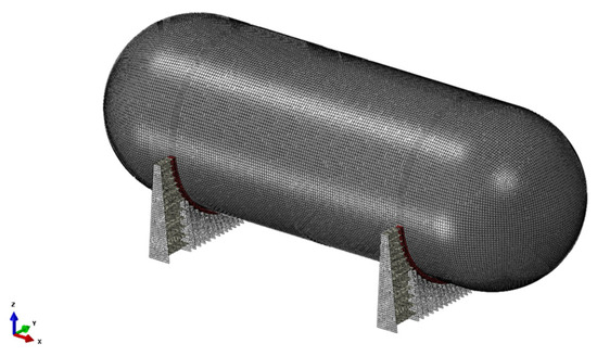
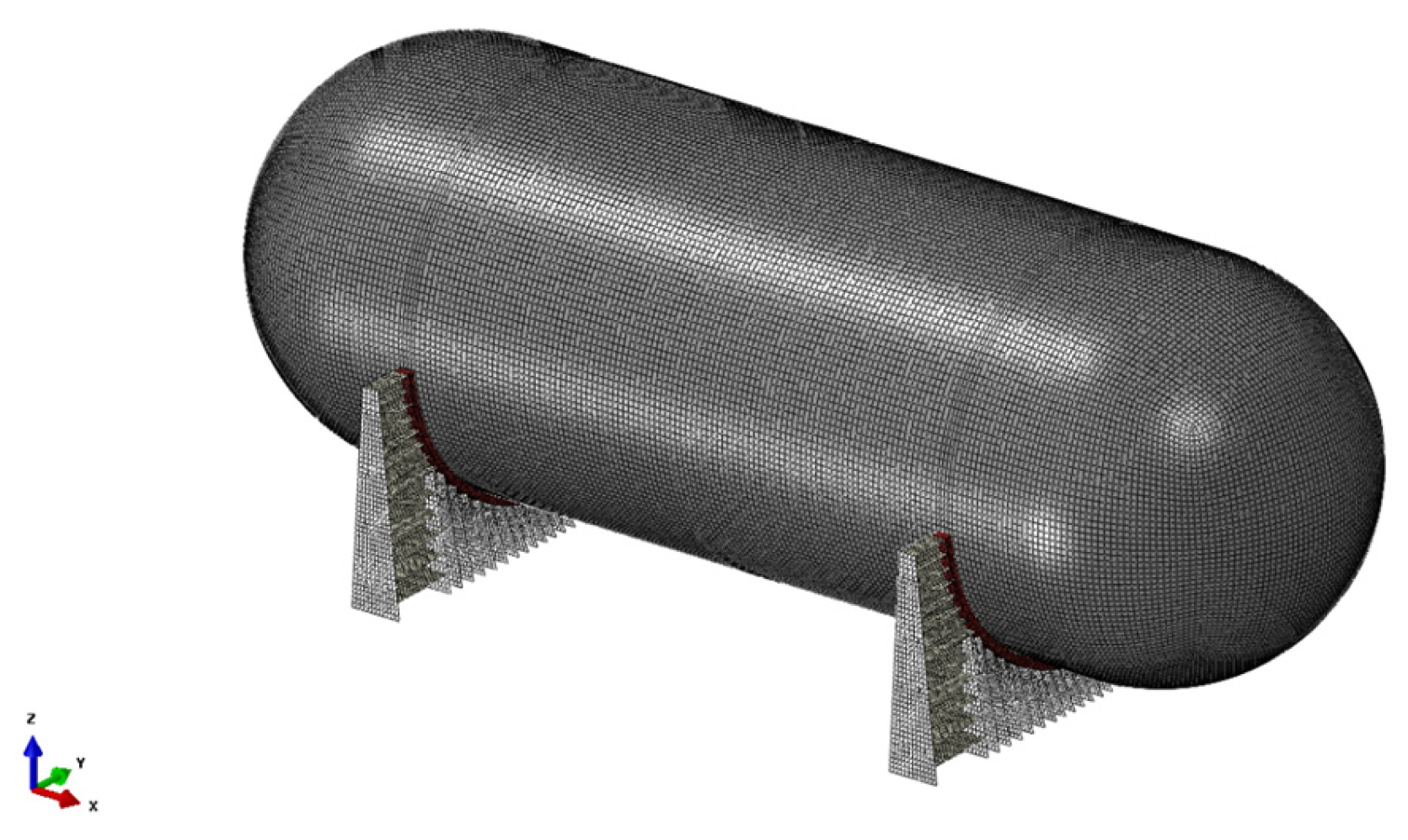
The finite element model used in this study is illustrated in Figure 3, which shows the mesh discretization and contact regions at the saddle supports. A relatively refined mesh was applied in regions of expected stress concentration, such as the saddle contact areas, while a coarser mesh was used in regions with relatively uniform stress distribution. The mesh configuration and element types adopted for each component are summarized in Table 5. This modeling strategy ensures an appropriate balance between computational efficiency and solution accuracy. The adopted mesh sizes were selected based on best-practice guidelines for shell FEA of cylindrical pressure vessels. The 200 mm S4R discretization of the tank shell corresponds to an element-size-to-thickness ratio of 4:1, which is within the established adequate range of 3:1 to 5:1 for accurate capture of membrane and bending response without shear locking. Locally refined meshes are applied at the saddle contact regions to resolve stress concentrations at the critical load transfer interfaces. A formal mesh convergence study is identified as a direction for future work.
Figure 3.
Finite element model of the Type C tank system showing mesh discretization and support boundary conditions.
Table 5.
Summary of finite element model.
The analysis was conducted under linear elastic assumptions to evaluate structural response within allowable stress limits. The model incorporates the thickness design obtained from the design pressure calculation, ensuring consistency between the design and verification stages.
3.3. Loading Conditions
The structural response of the Type C tank was evaluated under representative loading conditions corresponding to realistic marine operating scenarios. The applied load cases were selected to reflect the combined effects of internal pressure, cargo weight, and ship-induced accelerations.
A total of five load cases were considered:
- -
- LC1: maximum longitudinal acceleration;
- -
- LC2: maximum transverse acceleration;
- -
- LC3: maximum vertical acceleration;
- -
- LC4: 30° heeling condition;
- -
- LC5: collision condition.
The acceleration components were defined based on typical design values for liquefied gas carriers. The maximum accelerations considered in this study were 0.25 g in the longitudinal direction, 0.70 g in the transverse direction, and 0.87 g in the vertical direction.
In all load cases, the following loads were simultaneously applied:
- -
- Internal design pressure determined in Section 3.1;
- -
- Static and dynamic liquid head pressure;
- -
- Self-weight of the tank and supporting structures;
- -
- Thermal loads associated with the temperature difference between the storage condition and ambient environment.
Both static and dynamic load components were considered in each load case to capture the combined loading effects acting on the tank structure. The 30° heeling condition was included to evaluate asymmetric load distribution and its influence on stress concentration, particularly near the saddle supports. The collision condition (LC5) represents an extreme loading scenario defined in accordance with the IMO IGC Code, in which a forward longitudinal inertial force of 0.5 g is applied to the fully loaded cargo containment system. This criterion is adopted in Korean Register structural evaluation guidance for Type C tanks and is intended to verify structural integrity under emergency scenarios such as a forward collision. These load cases enable identification of the governing structural response under both normal operating and extreme conditions. The loading conditions considered in this study are summarized in Table 6.
Table 6.
Summary of design load cases and applied acceleration conditions.
4. Structural Analysis Results
4.1. Thermal Response
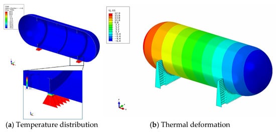
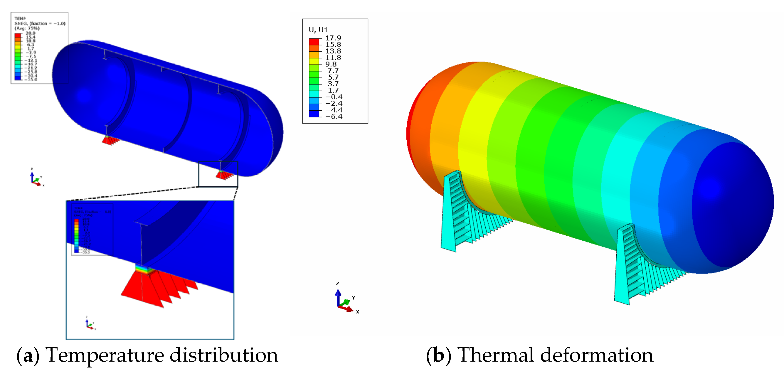
The thermal response of the tank structure was evaluated to assess the influence of temperature differences between the cryogenic storage condition and the ambient environment. The applied temperature distribution and the resulting deformation are shown in Figure 4. As shown in Figure 4a, the tank inner surface was subjected to −35 °C, while the saddle structures remained at ambient temperature, resulting in a localized thermal gradient at the interface between the tank, support wood, and saddle. The temperature variation is primarily concentrated in the support region due to thermal mismatch between the cryogenic tank and ambient structures. The corresponding thermal deformation is presented in Figure 4b. Due to the boundary condition in which one saddle is fixed and the other allows sliding, the tank undergoes longitudinal contraction along its axis. The total contraction was approximately 18 mm.
Figure 4.
Thermal response of the tank structure under low temperature condition.
This deformation behavior indicates that the thermal load is largely accommodated through global shrinkage of the structure rather than inducing significant constraint stresses. As a result, the thermal stresses remain relatively low. The maximum von Mises stresses obtained from the thermal analysis are summarized in Table 7. The highest stress occurs in the saddle structure (47.2 MPa), followed by the tank shell (26.2 MPa) and support wood (15.5 MPa). All stress values are significantly lower than the corresponding allowable limits, confirming that the thermal loading does not compromise structural safety. These results demonstrate that thermal loading contributes primarily to deformation rather than stress, and therefore does not govern the structural design of the tank.
Table 7.
Maximum von Mises stress under thermal loading.
4.2. Structural Response Under Loading Conditions
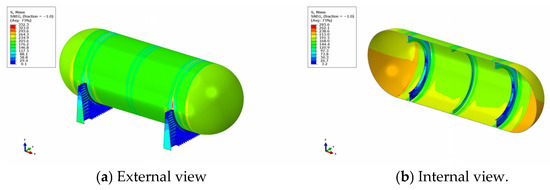
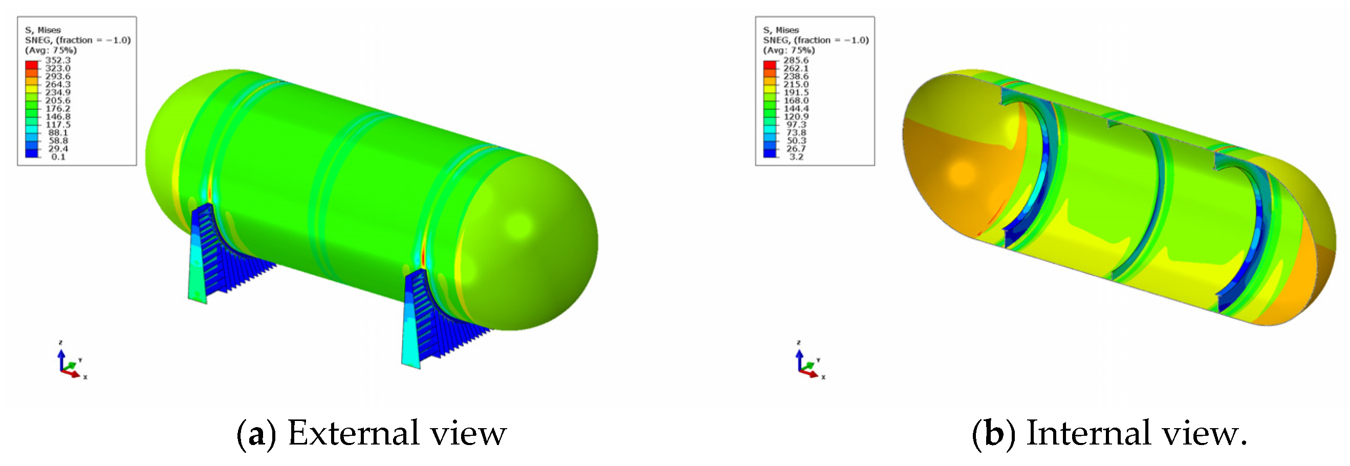
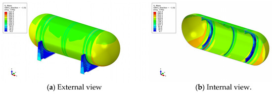
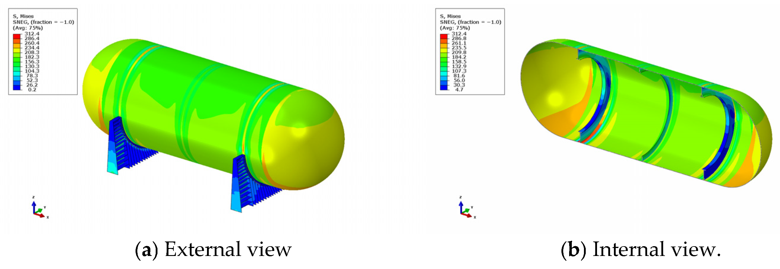
The structural behavior of the Type C tank was evaluated under the five representative load cases defined in Section 3.3. Representative stress distributions for selected load cases (LC2, LC3, and LC5) are shown in Figure 5, Figure 6 and Figure 7.
Figure 5.
Stress distribution under LC2 (maximum transverse acceleration).
Figure 6.
Stress distribution under LC3 (maximum vertical acceleration).
Figure 7.
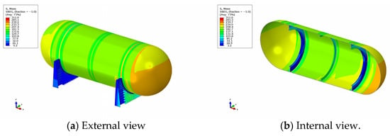
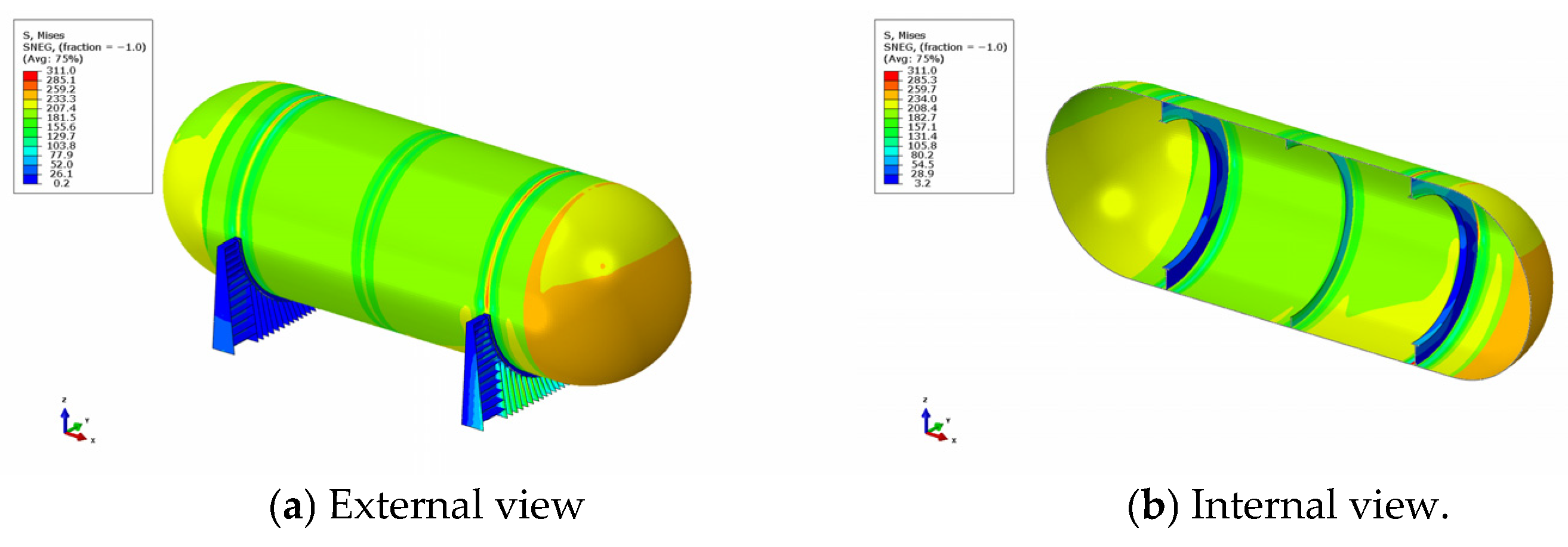
Stress distribution under LC5 (collision condition).
In all loading conditions, the highest stress concentrations are consistently observed near the saddle support regions, particularly at the junction between the tank shell and the support ring. This indicates that the structural response is primarily governed by local load transfer mechanisms at the supports rather than by global shell behavior.
Among the considered load cases, LC2 (maximum transverse acceleration) produced the highest stress level. As shown in Figure 5, pronounced stress concentration occurs near the saddle region due to asymmetric load distribution induced by transverse acceleration. The maximum von Mises stress reached 352.3 MPa in the tank shell, which approaches the allowable limit but remains within the permissible range.
For comparison, Figure 6 presents the stress distribution under LC3 (maximum vertical acceleration), where the stress is more uniformly distributed along the tank shell due to the combined effect of gravity and vertical inertial loading. Although the overall stress level is significant, it is lower than that observed in LC2.
Figure 7 illustrates the stress distribution under LC5 (collision condition), representing an extreme loading scenario. In this case, elevated stress is observed near the forward region of the tank and the saddle supports due to increased longitudinal inertial forces. However, the maximum stress remains below the allowable limits.
The maximum von Mises stresses for all load cases are summarized in Table 8, together with the corresponding allowable limits. All stress values remain below the allowable limits for the tank shell, saddle structures, and support wood, confirming structural safety under all considered loading conditions.
Table 8.
Maximum von Mises stress and allowable limits for all load cases.
Among all cases, LC2 clearly governs the structural design, as it produces the highest stress level. This behavior is consistent with the load transfer mechanism in saddle-supported pressure vessels, where transverse acceleration induces the most severe asymmetric loading. To clarify the interaction mechanism: under LC2, the transverse liquid head pressure is applied as a hydrostatic distribution proportional to the transverse acceleration (0.70 g) and cargo density, referenced to the lowest water-level point in the transverse direction. This asymmetric loading induces lateral bending of the tank shell, concentrating the reaction force at the fixed saddle junction via the support ring. At the fixed saddle, tie constraints at the tank–wood interface fully restrain all relative motion, transmitting the combined vertical and lateral reaction to the hull. At the sliding saddle, the absence of tank–wood tie constraints prevents accumulation of additional transverse constraint forces, isolating the critical stress concentration to the fixed saddle region.
4.3. Additional Structural Assessments
In addition to the primary structural analysis, supplementary evaluations were conducted to assess buckling resistance and fatigue-related design considerations in accordance with classification requirements. The buckling strength of the tank was evaluated using linear eigenvalue analysis based on the design external pressure defined in the IGC Code. The design external pressure was calculated as the combined effect of vacuum pressure, insulation weight, and other external loads, resulting in a total value of 0.035 MPa.
The first three buckling eigenvalues were obtained as 17.91, 17.91, and 20.28, respectively, which significantly exceed the minimum safety factor requirement of 3. This indicates that the tank structure possesses sufficient resistance against buckling under the given loading conditions. It is noted that the 50 mm shell thickness adopted in this study is governed by the internal design pressure of 18 barg, not by buckling requirements. As a result, the structure inherently possesses a large buckling reserve: the obtained eigenvalues exceed the required safety factor of 3.0 by a factor of approximately six. While linear eigenvalue analysis provides an upper bound of the actual buckling load, and geometric imperfections or material nonlinearity may reduce the actual resistance, applying a typical knockdown factor of 0.5–0.7 for cylindrical shells still yields an effective safety factor of approximately 8–12—well above the minimum requirement. Therefore, the linear eigenvalue approach is considered adequate for this pressure-dominated configuration, and a nonlinear buckling analysis is not warranted. The IGC Code minimum design vapor pressure formula (Equation (2)) is itself derived from fracture mechanics-based fatigue crack propagation criteria: it defines the minimum vapor pressure at which the primary membrane stress σ_m is sufficiently low that an initial surface flaw of assumed depth a0 = 0.2 t will not propagate beyond half the shell thickness over the vessel’s service life, given an allowable dynamic membrane stress Δσ_A = 55 N/mm2 for ferritic-pearlitic steels. Satisfying this minimum vapor pressure criterion is therefore both necessary and sufficient to ensure fatigue safety of the tank shell. In the present study, the actual design vapor pressure of 15 barg substantially exceeds the rule-based minimum of 10.3 barg, and the resulting shell thickness of 50 mm is correspondingly greater than the minimum criterion alone would require. The fatigue criterion for the tank shell is therefore self-evidently satisfied with margin, and no additional fatigue evaluation is necessary for the present configuration.
In the present study, since the design pressure exceeds the minimum vapor pressure requirement, the fatigue-related criteria are inherently satisfied without the need for additional fatigue analysis. This is consistent with the design philosophy of Type C tanks, where pressure-based design implicitly ensures fatigue safety. These results confirm that both buckling and fatigue do not govern the structural design in the present configuration.
4.4. Governing Design Factors
Based on the comprehensive structural analyses, it is evident that the design of the Type C tank is predominantly governed by internal pressure rather than other load components. Although ship-induced accelerations and liquid head pressure contribute to variations in stress distribution, their influence remains secondary compared to the internal pressure associated with liquefaction conditions and boil-off gas (BOG) accumulation. This is demonstrated by the fact that the highest stress levels observed under transverse acceleration (LC2) approach the allowable limits primarily due to the pressure-determined shell thickness. In the present design, the required shell thickness approaches the upper practical limit of approximately 50 mm. This thickness is primarily dictated by the internal design pressure rather than by external loads or classification rule minimum requirements. As a result, the increased structural stiffness inherently reduces the relative influence of secondary load effects, including thermal stress, external pressure, and local acceleration-induced loads.
Furthermore, the supplementary assessments indicate that both buckling and fatigue criteria are satisfied with sufficient safety margins once the pressure-driven thickness is applied. This confirms that these factors do not govern the design under the considered operating conditions. These observations clearly indicate that the design of Type C tanks for LCO2 storage is fundamentally pressure-driven, rather than governed by rule-based minimum design pressure or secondary loading conditions.
From a practical design perspective, this suggests that accurate estimation of internal pressure—particularly considering BOG accumulation and operational scenarios—is more critical than detailed refinement of secondary load components. Therefore, future design optimization efforts should prioritize pressure evaluation and management rather than structural configuration adjustments.
4.5. Discussion
The present results collectively demonstrate that the structural design of IMO Type C tanks for medium-pressure LCO2 storage is fundamentally governed by the internal design pressure of 18 barg, which is driven by thermodynamic storage conditions (initial vapor pressure 14 barg at −35 °C, plus approximately 1 bar BOG accumulation over 30 days) rather than the classification rule-based minimum of 10.3 barg. The resulting shell thickness of 50 mm—approaching the practical fabrication limit for a 13.4 m diameter vessel—inherently provides sufficient structural stiffness to satisfy all secondary structural criteria without additional design intervention: the buckling safety factor (minimum eigenvalue 17.91) exceeds the required value of 3.0 by a factor of approximately six, and the fatigue criterion is self-evidently satisfied as discussed in Section 4.3.
Among the five load cases examined, LC2 (transverse acceleration, 0.70 g) produces the most critical stress state (352.3 MPa, 91.5% of allowable), consistent with the well-established governing role of transverse inertial loading in saddle-supported pressure vessels. The remaining load cases (LC1: 270.8 MPa, LC3: 312.4 MPa, LC4: 322.2 MPa, LC5: 311.0 MPa) all remain within allowable limits with greater margin. Thermal loading contributes a longitudinal contraction of approximately 18 mm but generates stresses well below allowable limits (maximum 47.2 MPa in the saddle structure), confirming the effectiveness of the fixed/sliding saddle arrangement in relieving thermal constraint forces.
These findings suggest that for LCO2 storage applications in this pressure−temperature regime, design effort is most productively directed toward accurate BOG pressure estimation rather than structural configuration optimization. The parametric sensitivity of BOG pressure rise to storage conditions, insulation performance, and holding time—and its implications for tank size-dependent design strategy—are discussed in detail in Ref. [17].
5. Conclusions
This study presented a structural integrity evaluation of a 5000 m3 IMO Type C tank for liquefied carbon dioxide (LCO2) storage under cryogenic and pressurized conditions based on the IGC Code and Korean Register rules. The main findings are summarized as follows:
- (1)
- The structural response of the tank is primarily governed by internal pressure associated with liquefaction conditions and boil-off gas (BOG) accumulation. The required shell thickness of 50 mm (minimum required: 48.2 mm) approaches the practical upper limit, which dominates the overall structural behavior. It should be noted that this pressure-driven characteristic is specific to the medium-pressure LCO2 storage scenario (15 barg, −35 °C, 5000 m3) where the thermodynamic vapor pressure substantially exceeds the rule-based minimum. For lower storage pressures, smaller tank capacities, or cargoes with lower saturation pressures, the rule-based minimum design pressure may govern and the relative influence of secondary loads would increase accordingly.
- (2)
- Among the considered loading conditions, transverse acceleration (LC2) produces the highest stress level (maximum von Mises stress of 352.3 MPa, utilization ratio: 91.5%) due to asymmetric load distribution at the saddle supports. However, all stress values remain within allowable limits, confirming structural safety.
- (3)
- Thermal loading induces a total longitudinal contraction of approximately 18 mm and mainly causes global shrinkage deformation rather than significant constraint stresses, with maximum von Mises stresses of 47.2 MPa in the saddle structure, well within allowable limits.
- (4)
- Buckling and fatigue criteria are inherently satisfied once the pressure-driven shell thickness is applied, indicating that these factors do not govern the structural design in the present configuration. This conclusion is contingent on the pressure-driven shell thickness approaching the practical fabrication limit; configurations with lower internal pressures and thinner shells may require independent buckling evaluations.
Overall, the results demonstrate that the design of type C tanks for LCO2 storage is fundamentally pressure-driven. This suggests that accurate estimation of internal pressure, particularly considering BOG accumulation, is more critical than detailed refinement of secondary loading conditions. The findings provide practical insights for efficient and rational design of LCO2 storage systems in marine applications.
Author Contributions
Conceptualization, J.L.; methodology, Y.S. and J.L.; formal analysis, Y.S.; software, J.L.; validation, Y.S. and J.L.; investigation, Y.S.; resources, J.L.; writing—original draft preparation, Y.S. and J.L.; writing—review and editing, J.L.; visualization, Y.S.; supervision, J.L. All authors have read and agreed to the published version of the manuscript.
Funding
This research was supported by Korea Institute of Marine Science & Technology Promotion (KIMST) funded by the Ministry of Oceans and Fisheries (RS-2024-00420021).
Data Availability Statement
Data are contained within the article.
Conflicts of Interest
The authors declare no conflicts of interest.
References
- IPCC. Climate Change 2022: Mitigation of Climate Change; Cambridge University Press: Cambridge, UK, 2022. [Google Scholar]
- IEA. CCUS in Clean Energy Transitions; International Energy Agency: Paris, France, 2020. [Google Scholar]
- Global CCS Institute. Global Status of CCS 2023; Global CCS Institute: Melbourne, Australia, 2023. [Google Scholar]
- Aspelund, A.; Jordal, K. Gas conditioning—The interface between CO2 capture and transport. Int. J. Greenh. Gas Control 2007, 1, 343–354. [Google Scholar] [CrossRef] [Scilit]
- IEAGHG. Ship Transport of CO2; Report No. 2011/04; IEAGHG: Cheltenham, UK, 2011. [Google Scholar]
- ABS. Requirements for Liquefied Carbon Dioxide Carriers; American Bureau of Shipping: Houston, TX, USA, 2024. [Google Scholar]
- Span, R.; Wagner, W. A New Equation of State for Carbon Dioxide Covering the Fluid Region from the Triple Point Temperature to 1100 K at Pressures up to 800 MPa. J. Phys. Chem. Ref. Data 1996, 25, 1509–1596. [Google Scholar] [CrossRef] [Scilit]
- Lemmon, E.W.; Huber, M.L.; McLinden, M.O. NIST REFPROP, Version 10.0; NIST: Gaithersburg, MD, USA, 2022.
- de Visser, E.; Hendriks, C.; Barrio, M.; Mølnvik, M.J.; de Koeijer, G.; Liljemark, S.; Le Gallo, Y. Dynamis CO2 quality recommendations. Int. J. Greenh. Gas Control 2008, 2, 478–484. [Google Scholar] [CrossRef] [Scilit]
- ABS. Guide for CO2 Transport Vessels; American Bureau of Shipping: Houston, TX, USA, 2022. [Google Scholar]
- IMO. International Code for the Construction and Equipment of Ships Carrying Liquefied Gases in Bulk (IGC Code); IMO: London, UK, 2016. [Google Scholar]
- Korean Register. Rules for Classification of Steel Ships; Korean Register: Busan, Republic of Korea, 2024. [Google Scholar]
- ABS. Strength Assessment of Independent Type C Tanks; ABS: Houston, TX, USA, 2022. [Google Scholar]
- Paik, J.K.; Thayamballi, A.K. Ultimate Limit State Design of Steel-Plated Structures; Wiley: Chichester, UK, 2003. [Google Scholar]
- Park, Y.-I.; Cho, J.-S.; Kim, J.-H. Structural Integrity Assessment of Independent Type-C Cylindrical Tanks Using Finite Element Analysis: Comparative Study Using Stainless Steel and Aluminum Alloy. Metals 2021, 11, 1632. [Google Scholar] [CrossRef] [Scilit]
- Choi, U.; Chang, D.; Jo, C. Estimation of the design pressure of a prismatic LNG storage vessel. Ocean Eng. 2015, 101, 40–46. [Google Scholar] [CrossRef] [Scilit]
- Choi, Y.; Lee, J.; Lee, J.M. Comparative study of vapor pressure requirements for rule-based design of IMO Type C tanks for LCO2: Guidelines for optimizing pressure conditions. Int. J. Nav. Archit. Ocean Eng. 2025, 17, 100668. [Google Scholar] [CrossRef] [Scilit]

Disclaimer/Publisher’s Note: The statements, opinions and data contained in all publications are solely those of the individual author(s) and contributor(s) and not of MDPI and/or the editor(s). MDPI and/or the editor(s) disclaim responsibility for any injury to people or property resulting from any ideas, methods, instructions or products referred to in the content. |
© 2026 by the authors. Licensee MDPI, Basel, Switzerland. This article is an open access article distributed under the terms and conditions of the Creative Commons Attribution (CC BY) license.