


Abstract
This paper presents a numerical investigation of vortex-induced vibration (VIV) of six elastically mounted circular cylinders in oscillatory flow, three smooth and three biofouled with triangular surface roughness elements. The study aims to characterise the influence of the longitudinal spacing ratio ( and ) on the two-degree-of-freedom (2DOF) vibration response at a constant Keulegan–Carpenter number of . Simulations are performed using the transient RANS equations with the SST turbulence model, and structural motion is resolved using a dynamic mesh approach. Lock-in behaviour is observed over the reduced velocity range . Biofouled cylinders generally exhibit higher in-line displacement amplitudes than smooth cylinders in the initial and lower lock-in branches, whereas smooth cylinders tend to attain higher in-line amplitudes in the upper lock-in branch. The spacing ratio is found to significantly influence the response, with peak vibration amplitudes varying non-uniformly across the array and no single spacing configuration being optimal for all cylinders. This behaviour is further supported by analyses of trajectories, frequency content, and vorticity fields. Among the smooth cylinders, the middle cylinder exhibits the largest in-line displacement amplitude of at and the largest cross-flow displacement of at . For the biofouled configurations, the middle and upstream cylinders show the highest in-line displacement amplitude of at , while the maximum cross-flow displacement of is observed for the upstream cylinder at .
1. Introduction
Vortex-induced vibration (VIV) is a major driver of fatigue and reliability concerns in slender offshore structures, including risers, flow lines, mooring lines, and umbilicals, used in offshore energy production [1,2,3,4]. While VIV of isolated cylinders in uniform steady flows has been extensively studied, offshore installations commonly involve arrays of closely spaced structural elements, exposed to time-varying flows, and their hydrodynamic interaction can significantly modify vortex shedding and structural response. In realistic ocean environments, these structures are also subject to biofouling caused by the accumulation of marine organisms, the growth of which depends on the depth [5,6,7] and changes the effective geometry of structural members. Marine growth rarely develops uniformly across an array, often producing mixed configurations, in which some elements remain relatively clean, while others are biofouled with a different coverage ratio. Such heterogeneous conditions fundamentally alter wake interference and vibration dynamics, and understanding the VIV behaviour of partially biofouled structural arrays in time-varying flows is an essential challenge for the offshore industry on the pathway to the structural integrity and longevity of slender elements.
The central problem in VIV analysis is the prediction of a lock-in or synchronisation condition, which often manifests in increasing fluid forces acting on the structure, increased displacement amplitudes of the structure and nearly constant values of the vibration frequency for a range of flow velocities. The lock-in state develops when the vortex shedding frequency approaches the natural frequency of the structure, and this phenomenon is well described in reviews by [8,9,10]. The onset and extent of the lock-in regime is highly dependent on multiple structural and flow parameters. These include but are not limited to the structural parameters of the mass ratio [11,12], damping ratio [13], number of degrees of freedom [11,12], cross-sectional shapes [14,15], and the number and position of structures relative to each other in a group [16,17] and the flow parameters of the Reynolds number [13], sheared flow parameter [18], time variation [19], or the steadiness of the current.
Oscillatory flows, modelled using sinusoidal equations for flow velocity, represent one of the types of unsteady flows, approximating the impact of waves, tidal currents or combined wave–current flows. The velocity magnitude and direction in oscillatory flows vary periodically, which substantially complicates the synchronisation regimes of offshore structures, compared to the VIV dynamics observed in steady flows. Oscillatory flows are often characterised by the Keulegan–Carpenter (KC) number [20], and the first mapping of vortex shedding regimes based on this dimensionless quantity is performed in [21]. The first changes to the lock-in condition in oscillatory flows are reported in [22], and the time-varying nature of drag and added mass coefficients in oscillatory flows is discussed in [23]. Single-, double- and triple-frequency responses of a two-degree-of-freedom (2DOF) rigid structure are discussed in the numerical study by [24], which also finds that the dominant in-line vibration frequency is equal to the oscillatory flow frequency.
Oscillatory flows have even a more complex impact on fluid forces and structural dynamics when slender bodies are arranged in a group and wake interactions take place. Hydrodynamic forcing on multiple bluff circular objects in oscillatory flows is first discussed in [25], where a single structure, two structures and a group of 3-by-3 structures are considered in a series of experimental tests. Further work in [26,27] focuses on two circular cylinders in tandem and staggered arrangements, revealing complex vortex streets and patterns in the in-line force coefficient, related to the gap ratio. The investigation by [28] covers a side-by-side configuration of two square cylinders and suggests an empirical equation, connecting the in-line force coefficient with the KC number from the range of 1–15. The numerical work by [29] further examines tandem and side-by-side arrangements of circular structures for a range of gap ratios and KC numbers. Following this research, the comprehensive study by [30] considers the same gap ratios and similar KC numbers, but evaluates tandem, staggered and side-by-side arrangements of circular cylinders by altering the flow incidence angle. This work identifies four distinct flow regimes for tandem and side-by-side configurations and eleven regimes for staggered configurations. Two circular structures of different diameters are examined in [31,32], and the latter work reports a single-vortex regime and synchronisation of the lift-force frequency with the oscillatory flow frequency.
Arrays of four circular structures in square and diamond layouts in oscillatory flows are studied in [33,34]. The work by [33] for the square structural arrangement reveals reflection symmetry vortex shedding regimes, spatio-temporal symmetry regimes and symmetry-breaking regimes. The study by [34] for the diamond configuration identifies synchronous, quasi-periodic and desynchronized flow patterns, and reports flow maps for each gap ratio. These two works present the practical extent of the published knowledge about the dynamics of multiple bluff bodies in oscillatory flows. This literature survey indicates that configurations of three, five and a larger number of structures have not been considered in oscillatory flows in general: neither in the stationary setting, nor with one degree of freedom (1DOF), nor with 2DOFs.
The recent simulation research by [35] extends the branch of oscillatory flow VIV studies to the area of biofouling, considering a single 2DOF rigid structure with a hard marine growth. This investigation reveals the increasing lock-in duration in the reduced velocity range and increasing maximum vibration amplitudes in both directions of vibration with the increasing KC number. Less recent biofouling studies focus on the dynamics of 2DOF rigid structures [36] and tandem cylinders with marine growth [37] in uniform flows. It is generally reported that settling aquatic organisms reduce vibration amplitudes, which has a positive impact on the predicted lifespan of subsea structures and a negative impact on marine energy harvesting [38,39]. The current state of VIV-with-biofouling research indicates that only a limited number of works consider the dynamics of structural arrays [37,40], and partially biofouled groups of slender objects are not studied in general.
On the contrary, arrays of smooth slender structures in uniform flows are relatively well studied, and their first categorization dates back as far as [41]. This work by [41] identifies tandem, side-by-side and staggered arrangements of objects, which are further studied and mapped in terms of vortex shedding regimes in [42,43,44]. This research direction at present includes findings about fluid forces for an array of six bare structures by [19], including altered cross-sectional shapes, and about the vibration of a cluster of up to seventeen structures, as in [45], while the upstream cylinder is assumed to be fixed. The latter study indicates that resulting steady-state positions of considered objects are not necessarily symmetric relative to the fixed cylinder. Overall, large structural arrays are not considered in time-varying flows.
Building on the findings of [19,35] and the identified gaps in the published research, the current study attempts to investigate the VIV dynamics of a 2-by-3 structural array, subjected to the oscillatory flow of KC = 10 and aquatic organisms, settling on half of the members. This work presents a logical continuation of already undertaken investigations in the areas of the VIV dynamics of objects with biofouling, smooth cylinders in oscillatory flows and large groups of smooth slender structures, typically considered in uniform flows.
The paper is arranged as follows. Section 1 identifies reasonable research gaps during the literature survey. Section 2 presents the simulation methodology. Section 3 provides the problem description. Section 4 outlines the main results, and the limitations and directions for future research are listed in Section 5. Section 6 summarises the major contributions of this work.
2. Numerical Model
2.1. Flow Model
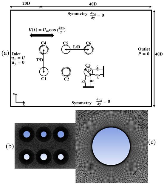
Six elastically mounted mixed circular 2DOF cylinders in array (three smooth cylinders and three biofouled cylinders), subjected to an oscillatory flow, are considered in this study and are illustrated in Figure 1a. The transient, incompressible 2D Reynolds-Averaged Navier–Stokes (RANS) equations are used to model the flow past these cylinders. The RANS system, which includes the continuity and momentum equations, is mathematically expressed as
where is the mean pressure, are average Cartesian components of the velocity vector, are the Reynolds stresses, is the fluid density, and is the mean viscous stress vector components, as follows:
where denotes the dynamic viscosity.
Figure 1.
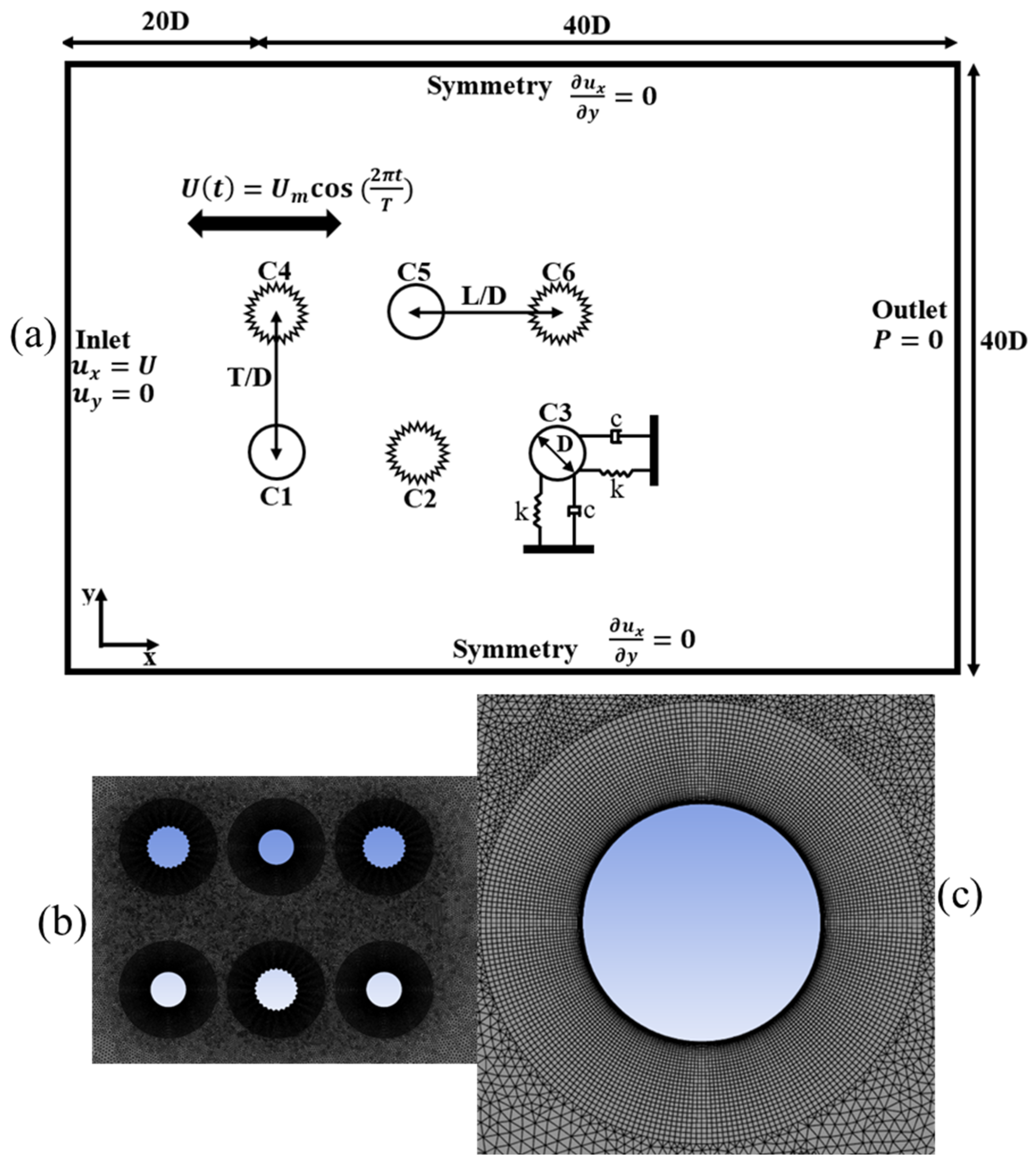
Array of six structures with partial biofouling in oscillatory flow: (a) schematic of the computational domain; (b) mesh around six cylinders with and without biofouling; (c) zoomed region around the cylinder.
To model turbulence and approximate eddy viscosity, the present study employs the Shear Stress Transport (SST) turbulence model, which includes transport equations for the turbulent kinetic energy k and specific dissipation rate ω:
where is the production term, is the eddy viscosity, is the velocity component in the j direction, is the empirically calibrated constant, is the dissipation coefficient, is the blended coefficient, is the near-wall diffusion coefficient, is the free-stream diffusion coefficient, and is the blending function activating near-wall behaviour.
Originally proposed in [46], this model has been shown in [47,48] to provide reliable predictions for flows subjected to adverse pressure gradients. However, the authors acknowledge that the use of a RANS-based framework with the SST model introduces limitations in resolving the unsteady wake dynamics associated with vortex-induced vibration. Since the RANS formulation is based on time-averaged governing equations, it tends to smooth transient flow structures and may underpredict peak force fluctuations, particularly under lock-in conditions at higher Reynolds numbers. Consequently, the predicted vibration amplitudes may be conservative.
These limitations should be considered when interpreting the computed oscillation amplitudes. Nevertheless, it is worth noting that two-dimensional RANS approaches remain widely used for flows within the present regime even at relatively high Reynolds numbers [49]. The applicability of the 2D RANS framework to capture the complexity of the three-dimensional complex phenomenon of flow-induced vibration is generally supported by studies [50,51,52]. In this work, the applicability of the 2D RANS framework is further supported by the mesh and time-step independence studies presented in Section 3.3, as well as the validation results discussed in Section 3.4. These assessments provide confidence that the overall trends reported herein remain physically meaningful and robust.
The simulations are performed using ANSYS Fluent 2025 R1, with the Pressure Implicit with Splitting of Operators (PISO) algorithm [53] used to solve the coupled pressure–velocity field at each time step, ensuring mass conservation. To accurately capture flow features such as wakes and shear layers while limiting numerical diffusion, a second-order scheme is applied for pressure, and a second-order upwind scheme is used for momentum. Gradients are computed using the Green–Gauss cell-based method, and a first-order implicit scheme is adopted for temporal discretisation.
The motion of the cylinders is prescribed using a user-defined function (UDF), and the dynamic mesh is handled through a combination of spring-based smoothing and remeshing. A size-based remeshing interval of 1 is applied, meaning that cell size criteria are evaluated at every time step. In addition, skewness-based remeshing is triggered when mesh quality exceeds a threshold of 0.85, preventing excessive cell distortion during cylinder motion. All cylinders are initially positioned at stationary equilibrium conditions before the start of the simulations.
The velocity of the oscillatory flow is mathematically formulated as
where and T are the amplitude and period of the oscillatory flow velocity, respectively.
The KC number is expressed as
where D is diameter of all cylinders, equal to 0.02 m.
The kinematic fluid viscosity and density of the fluid are set to be 10−6 m2/s and 998.2 kg/m3, respectively.
2.2. Structural Dynamic Model
From [53], oscillations of each elastically supported 2DOF cylinder are mathematically given as
where denotes the structure’s mass per unit length, is the damping coefficient per unit length, k is the stiffness coefficient per unit length of the elastic support, , are hydrodynamic forces acting in the in-line and transverse directions, and X and Y are the in-line and cross-flow displacements.
In the present study, six cylinders in the array are assumed to have the same structural properties, and these properties are identical in the in-line and cross-flow directions. The mass ratio of the cylinders is expressed as
where represents the mass of the displaced fluid, or
The reduced velocity and the natural frequency of the system are mathematically expressed respectively as
where
where the added mass coefficient is taken as 1 in the current work for simplicity.
3. Description of the Problem
3.1. Simulation Parameters
Vortex-induced vibrations of six elastically mounted circular cylinders are numerically investigated in the present study. Three cylinders (Cylinders 1, 3, and 5) are smooth, while the remaining three (Cylinders 2, 4, and 6) are fully biofouled.
The configuration is intentionally designed as a mixed system in which half of the cylinders are smooth and half are roughened by marine growth. This controlled setup allows the isolated effect of surface roughness to be examined within a multi-cylinder arrangement. By comparing smooth and biofouled cylinders under identical flow conditions, the influence of biofouling on wake interaction and vibration response can be more clearly identified.
In practical offshore environments, biofouling rarely develops uniformly across structural arrays. Variations in local flow conditions, shielding effects, and maintenance cycles often lead to heterogeneous distributions of marine growth. For instance, cylinders located in wake regions may experience different fouling characteristics compared to those directly exposed to the incoming flow. Accordingly, the present configuration represents an idealised yet physically plausible case of non-uniform biofouling. However, it does not capture the full complexity of irregular or partially distributed marine growth. Future work should therefore consider more realistic fouling patterns, including spatially non-uniform and stochastic roughness distributions, to better represent field conditions.
The cylinders are allowed to vibrate freely in both the in-line and cross-flow directions and are subjected to oscillatory flow at a constant Keulegan–Carpenter number of , consistent with [32]. The longitudinal spacing ratio is varied as 3, 4, and 5, while the transverse spacing ratio is kept constant at 4 throughout all simulations. The choice of is made to avoid vertical interaction between cylinders, as preliminary tests showed that may lead to vertical collision, which lies outside the scope of this study. A mass ratio of 1.62, following [54], and zero structural damping are adopted. The low mass ratio is representative of offshore pipeline applications, while zero damping is used to capture the upper-bound vibration response. As in [55], identical in-line and cross-flow natural frequencies are prescribed for each cylinder, with Hz. The reduced velocity is varied from 2 to 15 by adjusting the flow velocity, corresponding to a Reynolds number range of 955–7166, which lies within the subcritical regime for circular cylinders.
Biofouling is modelled as simplified two-dimensional barnacle-like roughness elements, each represented by triangular shapes with a height of 0.003 m, following [53]. A total of 25 elements are distributed around the cylinder circumference to ensure full surface coverage. In this study, the roughness elements are uniformly distributed, consistent with [56], although real marine biofouling is typically irregular and spatially non-uniform.
This idealisation does not aim to reproduce the exact morphology of marine organisms. Instead, it captures the dominant hydrodynamic effects of surface roughness, including earlier boundary-layer separation, enhanced shear-layer instability, and modifications to vortex shedding behaviour. The use of uniformly distributed triangular elements provides a controlled and repeatable representation of marine growth, suitable for parametric analysis. However, this modelling approach has inherent limitations, as discussed in Section 5. In particular, uniform roughness may overestimate the spatial coherence of wake structures compared with realistic heterogeneous fouling, where local clustering can introduce additional asymmetry and flow complexity. Consequently, the present model should be interpreted as an idealised roughness representation rather than a fully realistic biofouling configuration.
3.2. Computational Domain and Boundary Conditions
A 60D × 40D rectangular computational domain, similar to [57], is used in this current study, as shown in Figure 1a above. The upstream cylinders are positioned at 20D from the inlet boundary, which is specified as the velocity inlet and is mathematically presented as
with and being the flow velocities in the x and y directions respectively, and is the simulation time.
The outlet boundary, which is located at x = 40D, has a zero-gauge pressure and convective (zero-gradient) conditions for the velocity components
The top and bottom boundaries are given as symmetry [58], which is mathematically expressed as
No-slip conditions are imposed on the surface of all cylinders.
3.3. Mesh and Time-Step Tests
The computational grid around the cylinders is shown in Figure 1b. The computational domain is discretised using an unstructured triangular mesh, following a similar approach to [59]. A refined mesh is applied in the vicinity of the cylinder surfaces to satisfy the requirement . To this end, a first-layer cell height of m is used, together with a growth ratio of 1.2 and a total of 25 inflation layers. In addition, an edge sizing of m is imposed around the cylinder surfaces to further enhance local resolution.
To ensure the accuracy and mesh independence of the numerical results, a grid independence study is performed using four different meshes, based on the same structural parameters as in [57], wherein a mass ratio of 2.5 and zero damping are considered. The details of the grid configurations and corresponding results are presented in Table 1. Based on this analysis, Grid 3 is selected for the main simulations.
Table 1.
Mesh independence test results for the mass ratio of 2.5.
Furthermore, a validation case is carried out against the results of [60] for a two-degree-of-freedom vibration of a single smooth cylinder in oscillatory flow, using a mass ratio of 1.62 and a time step of 0.005 s. The comparison, presented in Table 2, shows good agreement with the published data. Further simulation is carried out for a 0.065 m diameter single biofouled cylinder oscillating in 1DOF by employing the same parameters as in [56] using Grid 3. The results of this simulation are presented in Table 3 against the data from [56], indicating that the model is capable of capturing the physics of the biofouled cylinders.
Table 2.
Mesh validation for the mass ratio of 1.62 and time step of 0.005 s for a single 2DOF cylinder in oscillatory flow.
Table 3.
Mesh validation for the mass ratio of 4.8 and time step size of 0.005 s for a single biofouled 1DOF cylinder in uniform flow.
To ensure that the results are not affected by temporal discretisation, a time-step sensitivity study is also conducted using Grid 3 and three different time-step sizes. The results are reported in Table 4, and a time step of 0.005 s is selected for the main simulations. Both the grid and time sensitivity analyses are based on the use of the cross-flow displacement amplitude as the primary comparison metric.
Table 4.
Time step independence test results for the mass ratio of 2.5.
3.4. Validation Test
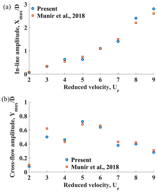
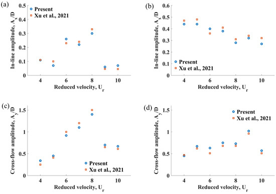
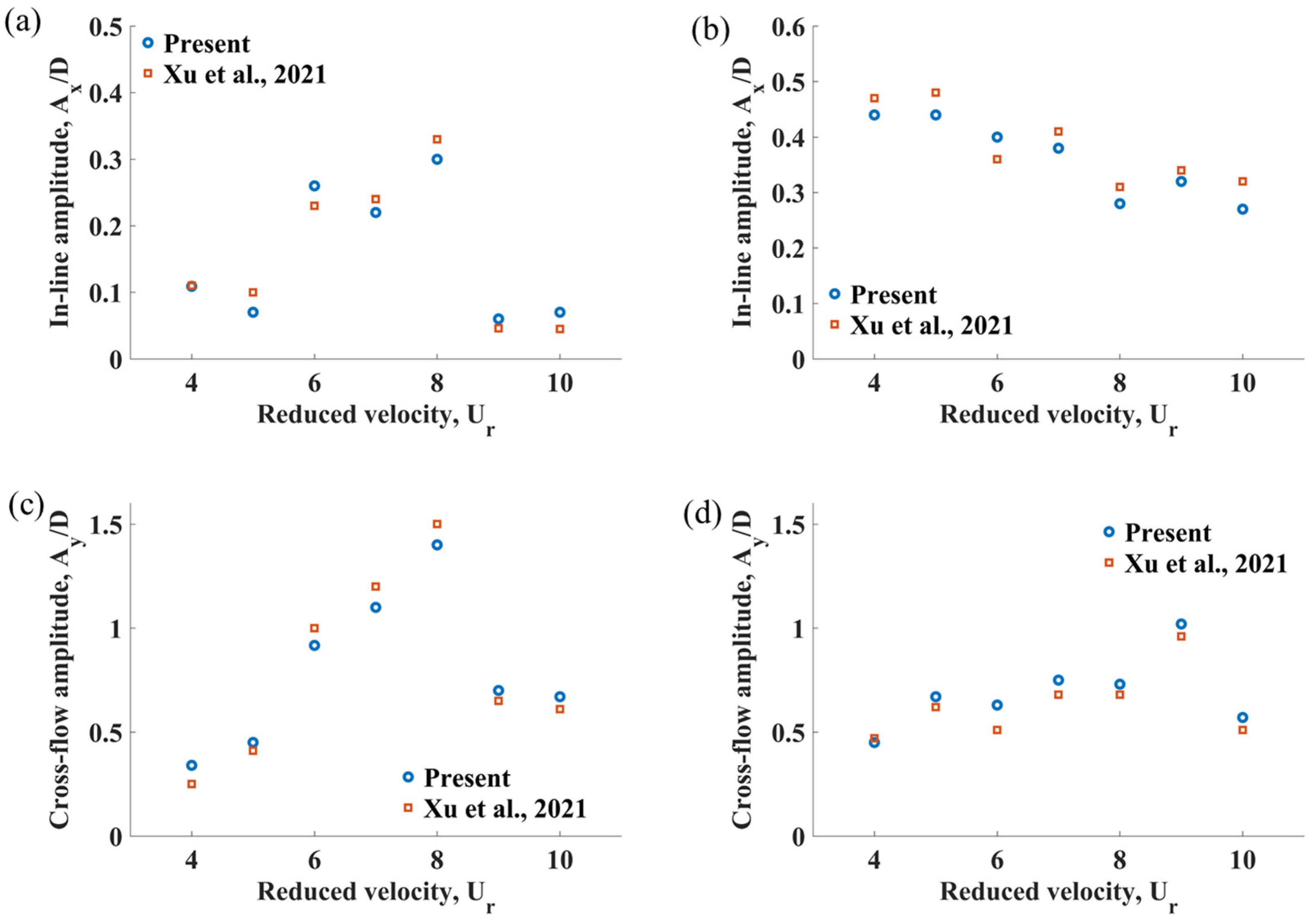
Further simulations are conducted to validate the numerical model for the vortex-induced vibration of an elastically mounted smooth circular 2DOF cylinder subjected to oscillatory flow at , using the same parameters as those reported in [61], as summarised in Table 5. Figure 2 presents a comparison of the in-line and cross-flow response amplitudes obtained in the present study with the numerical results of [61], showing good agreement between the two datasets. To ensure the grid capability of capturing the physics of the multiple cylinders accurately in this work, a validation test is performed for the two tandem smooth 2DOF cylinders for a reduced velocity ranging from 4 to 10 using the same parameters, as in [62]. The results for this validation test are shown in Figure 3 for L/D = 4.
Table 5.
Parameters for the validation test.
Figure 2.
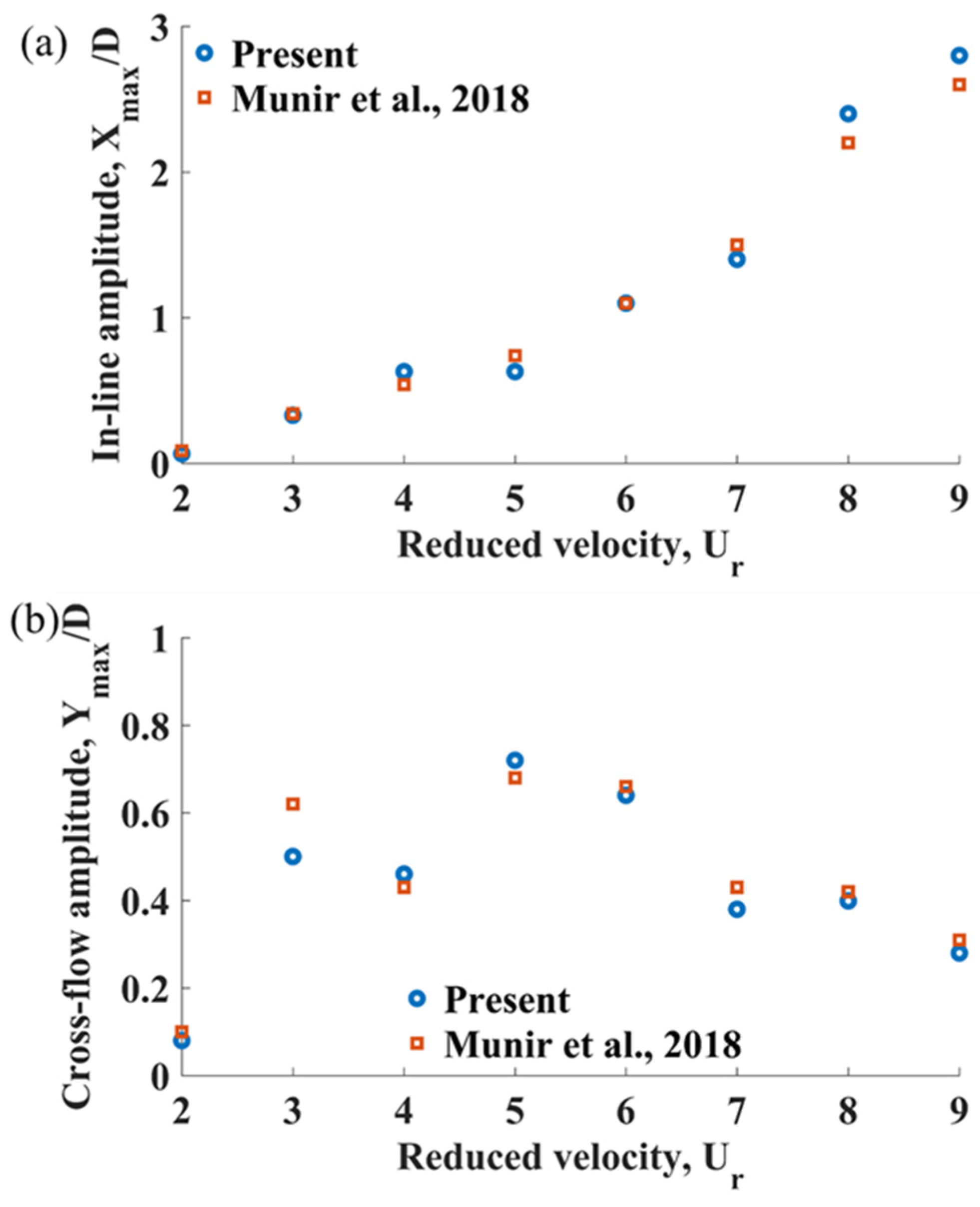
Comparison of maximum displacement amplitudes, generated using settings of Grid 3 and the time step of 0.005 s in the current work, with the results of [61]: (a) for the in-line direction; (b) for the cross-flow direction.
Figure 3.
Comparison of displacement amplitudes, obtained in the current work, with the results of [62]: (a) for the in-line direction for the upstream cylinder; (b) for the in-line direction for the downstream cylinder; (c) for the cross-flow direction for the upstream cylinder; (d) for the cross-flow direction for the downstream cylinder.
4. Results and Discussion
The present study numerically investigates the effect of the spacing ratio on the dynamics of six elastically mounted circular cylinders with two degrees of freedom and partial biofouling in an oscillatory flow at a constant Keulegan–Carpenter number of 10. The influence of on the vibration amplitudes, transverse frequency ratios, and the trajectories of the cylinders is examined.
The results are presented as follows. First, the overall response amplitudes of the six cylinders at are analysed to establish a reference behaviour. Next, the effect of on the vibration amplitudes is discussed. Finally, the cross-flow frequency ratios, the motion of individual cylinders at increasing spacing ratios, and the associated vortex shedding patterns are examined.
4.1. Response Amplitudes for the Six Cylinders at L/D = 5
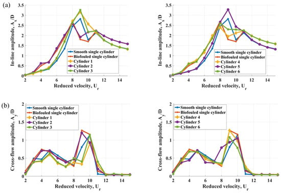
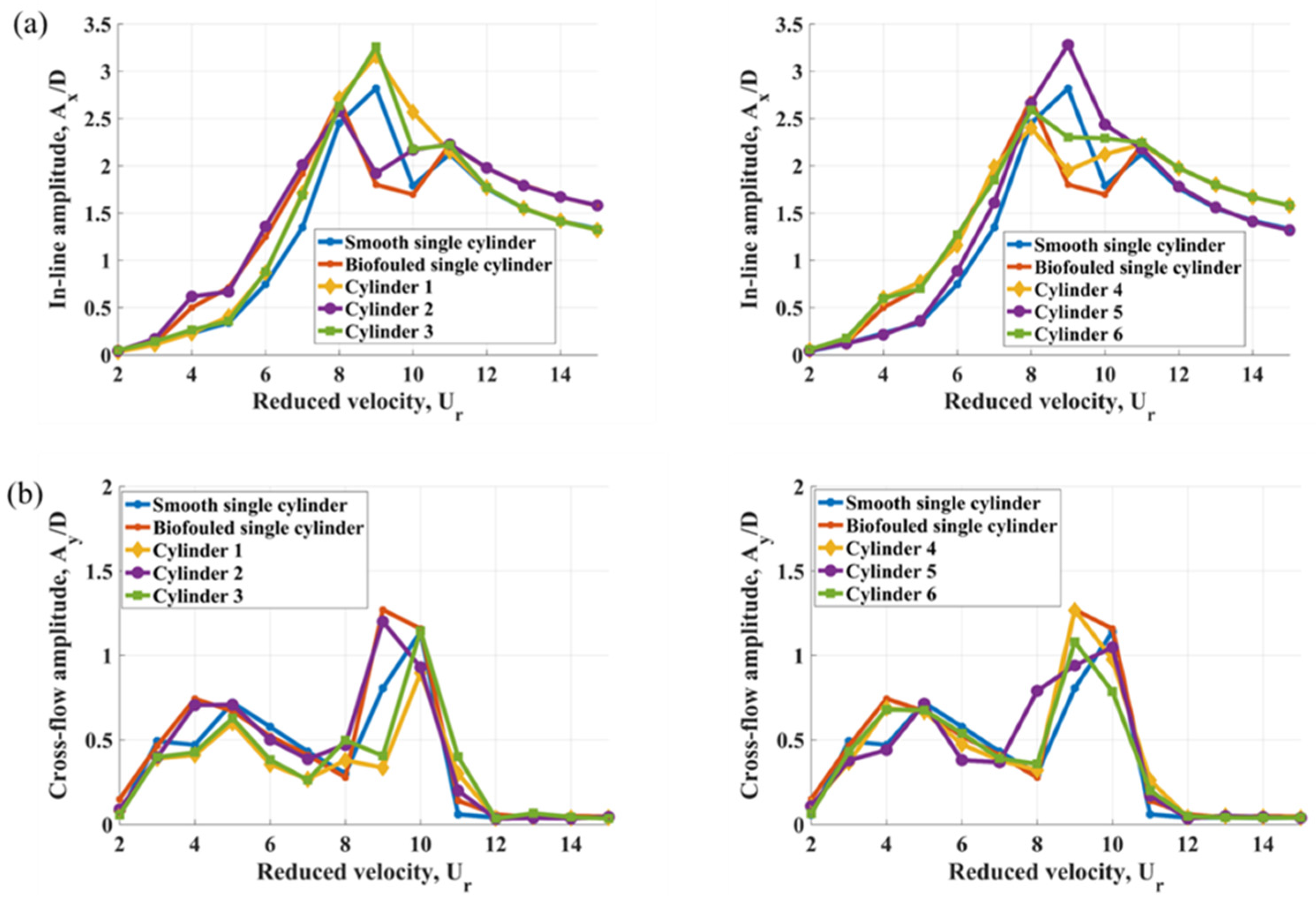
Figure 4 presents the in-line and cross-flow vibration amplitudes of the six-cylinder configuration at as a function of reduced velocity. For comparison, the responses of a single isolated smooth circular cylinder and a single isolated biofouled cylinder under identical flow conditions are also included. The vibration amplitudes are obtained from the time histories of cylinder displacements over 25 periods of the oscillatory flow. The in-line and cross-flow amplitudes are defined as and , respectively.
Figure 4.
Maximum displacement amplitudes for L/D = 5 for Cylinders 1–6 in: (a) the in-line direction; (b) the cross-flow direction.
Following [61], the lock-in range of reduced velocity is defined as the interval between the onset of the first response peak and the end of the last peak in cases where multiple lock-in peaks are observed. This definition is applicable to both the in-line and cross-flow responses shown in Figure 4. For , synchronisation between vortex shedding and structural motion occurs within the reduced velocity range , corresponding to the classical lock-in region for oscillatory flow past a circular cylinder.
For flow past single smooth and biofouled cylinders, the published literature reports differing trends in vibration response. Experimental studies [56,63] indicate a reduction in the maximum cross-flow amplitude for biofouled cylinders compared to smooth ones. In contrast, ref. [64] shows that at higher reduced velocities, particularly within the lock-in regime, roughened cylinders can exhibit larger amplitudes. Similarly, refs. [65,66] report that marine fouling alters the hydrodynamic behaviour of risers, potentially leading to increased oscillation amplitudes. The study in [35] provides a more nuanced perspective, demonstrating that in oscillatory flow where the in-line response is dominant, the upper branch amplitude of a smooth cylinder exceeds that of a biofouled cylinder, whereas the initial and lower branches are higher for the biofouled case.
The present results, shown in Figure 4a, are in overall agreement with [35]. In particular, the influence of surface roughness becomes more pronounced at higher reduced velocities, consistent with the observations of [64], where biofouled cylinders exhibit consistently larger cross-flow amplitudes than smooth cylinders. This behaviour can be attributed to the modification of the boundary layer by surface roughness: the presence of triangular fouling elements promotes earlier flow separation and enhances shear-layer instability, thereby intensifying the fluid–structure interaction.
As shown in Figure 4a, Cylinders 1 and 5 exhibit a single-peak lock-in response, whereas the remaining cylinders display two distinct peaks within the lock-in region. For the smooth cylinders, including the isolated case and Cylinders 1, 3, and 5, the maximum in-line displacement amplitudes occur at . In contrast, the biofouled cylinders, including the isolated case and Cylinders 2, 4, and 6, generally reach their peak in-line amplitudes at a lower reduced velocity, .
A similar trend is observed in Figure 4b for the cross-flow response. Biofouled cylinders attain their maximum cross-flow amplitudes at , whereas smooth cylinders reach their peak later, at . In the lower lock-in range (–5), the first cross-flow peak follows a consistent pattern: the largest amplitudes occur at for biofouled cylinders and at for smooth cylinders.
Within the lock-in region shown in Figure 4b, the cross-flow amplitudes increase significantly, reaching values up to for the biofouled single cylinder at , in agreement with [63]. Such large oscillations are characteristic of the super-upper response branch reported in previous vortex-induced vibration studies, e.g., [67].
A reduction in cross-flow amplitude is observed for all cases in the range , which can be attributed to partial desynchronization between the vortex shedding and the structural natural frequency. As the reduced velocity increases further, cross-flow oscillations diminish and eventually cease beyond for both the isolated cylinders and the cylinder array at all ratios. This behaviour is consistent with [61] for and with the observations of [35].
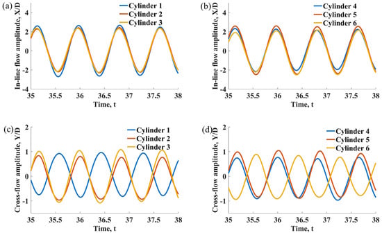
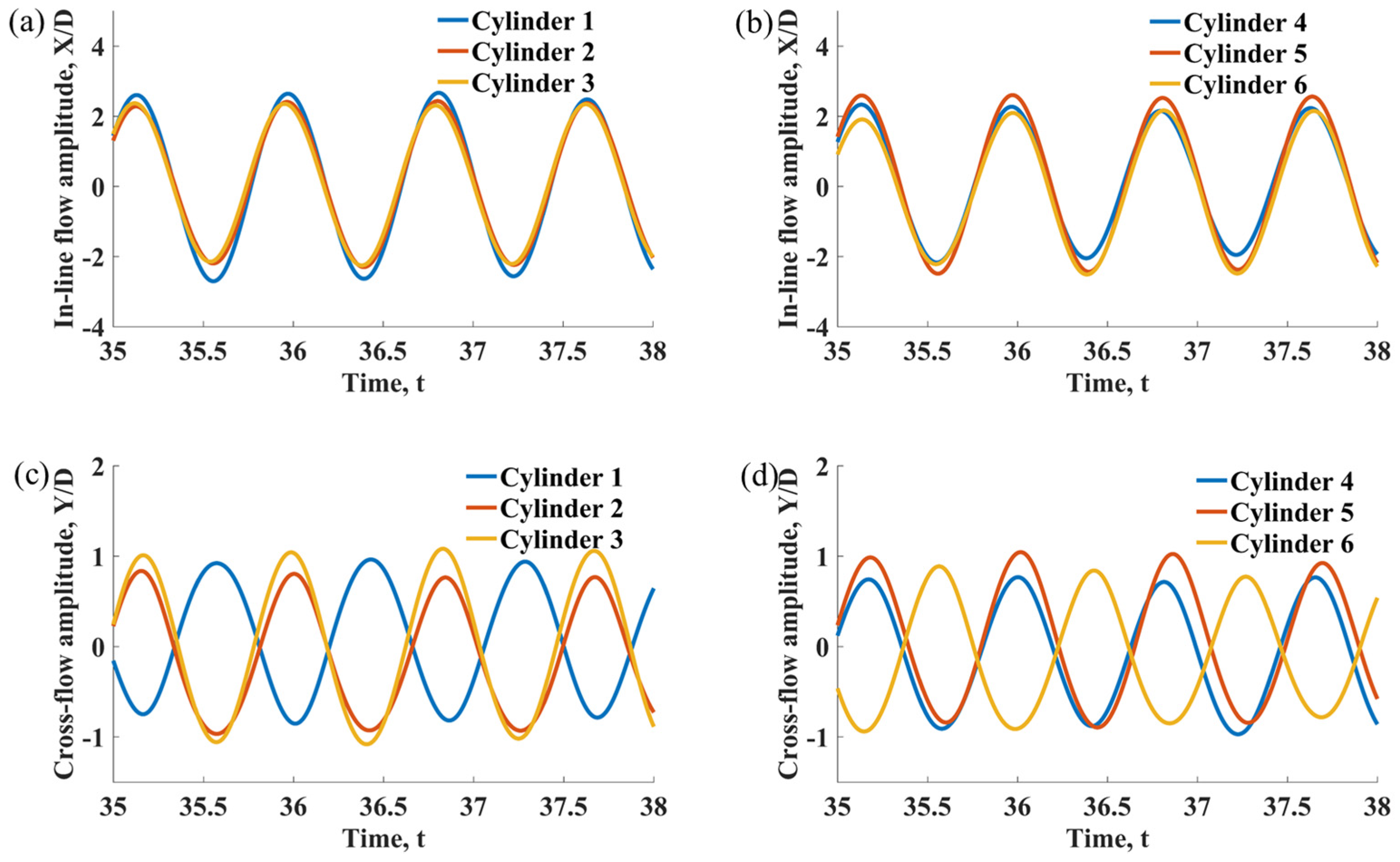
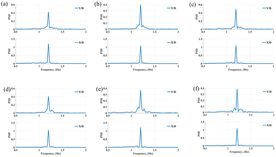
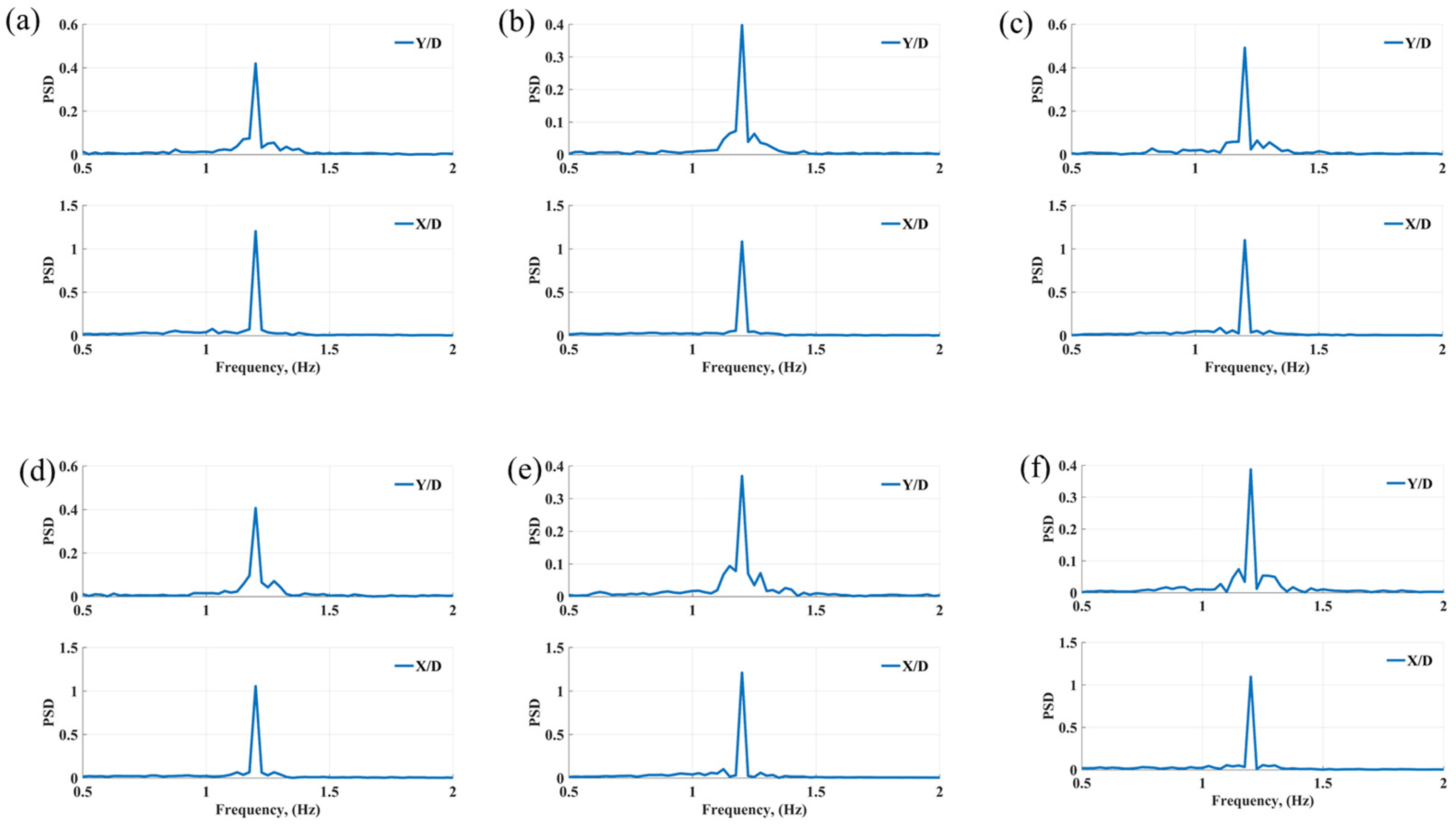
Figure 5 illustrates the time histories of the cylinder displacements. The in-line responses of all six cylinders are observed to be symmetric and predominantly in-phase. The corresponding FFT spectra in Figure 6 of both in-line and cross-flow motions at and indicate a single dominant frequency, demonstrating synchronisation between the structural response and the imposed oscillatory flow.
Figure 5.
Time histories of displacement signals of cylinders at L/D = 5 and = 10: (a) for Cylinders 1–3 in the in-line direction; (b) for Cylinders 4–6 in the in-line direction; (c) for Cylinders 1–3 in the cross-flow direction; (d) for Cylinders 4–6 in the cross-flow direction.
Figure 6.
FFT spectra of the cross-flow (top) and in-line (bottom) amplitude at L/D = 5 and = 10 of: (a) Cylinder 1; (b) Cylinder 2; (c) Cylinder 3; (d) Cylinder 4; (e) Cylinder 5; (f) Cylinder 6.
4.2. Response Amplitudes for Individual Cylinders at the Increasing L/D Ratio
In the present six-cylinder configuration, the vibration response varies significantly with both the relative position of the cylinders in the incoming flow and the spacing ratio. The upstream cylinders interact directly with the oscillatory inflow and therefore exhibit vibration characteristics similar to those of the isolated cylinders. Their response is primarily governed by synchronisation between vortex shedding and the structural natural frequency.
In contrast, the downstream cylinders are subjected to the wakes generated by the upstream bodies. These wakes contain coherent vortex structures that modify the local hydrodynamic forces acting on the downstream cylinders. When these vortices interact constructively with the structural motion, wake-induced excitation can lead to amplified oscillations. Conversely, the velocity deficit within the wake reduces the effective inflow velocity, weakening the hydrodynamic forcing and resulting in smaller vibration amplitudes. The variation in response across the array thus reflects the complex interplay between vortex-induced vibration and wake interference.
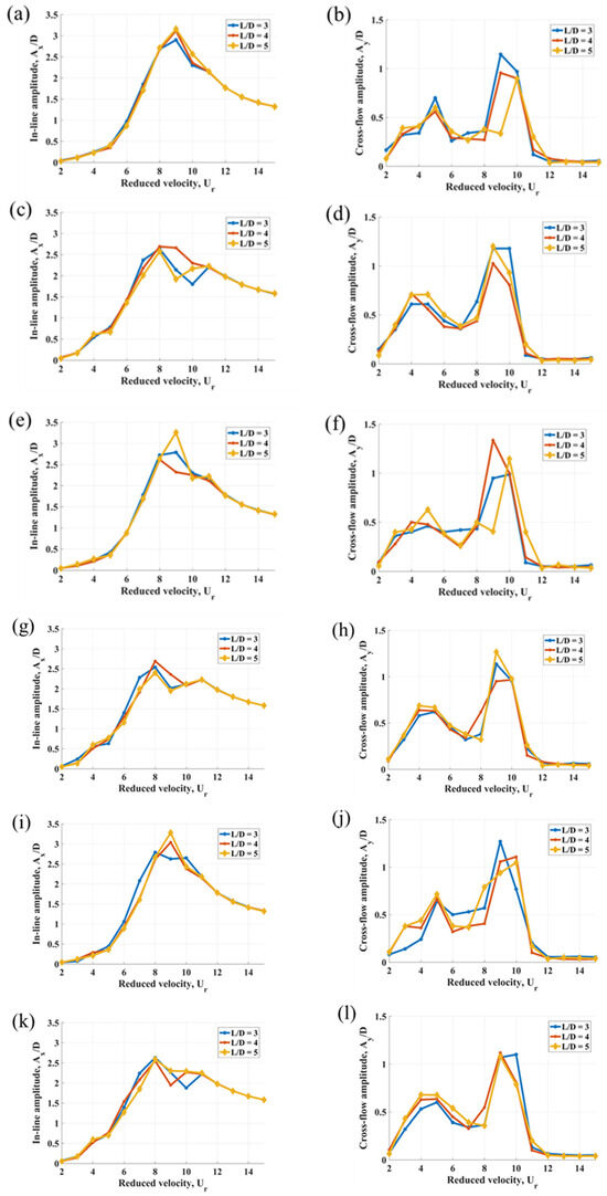
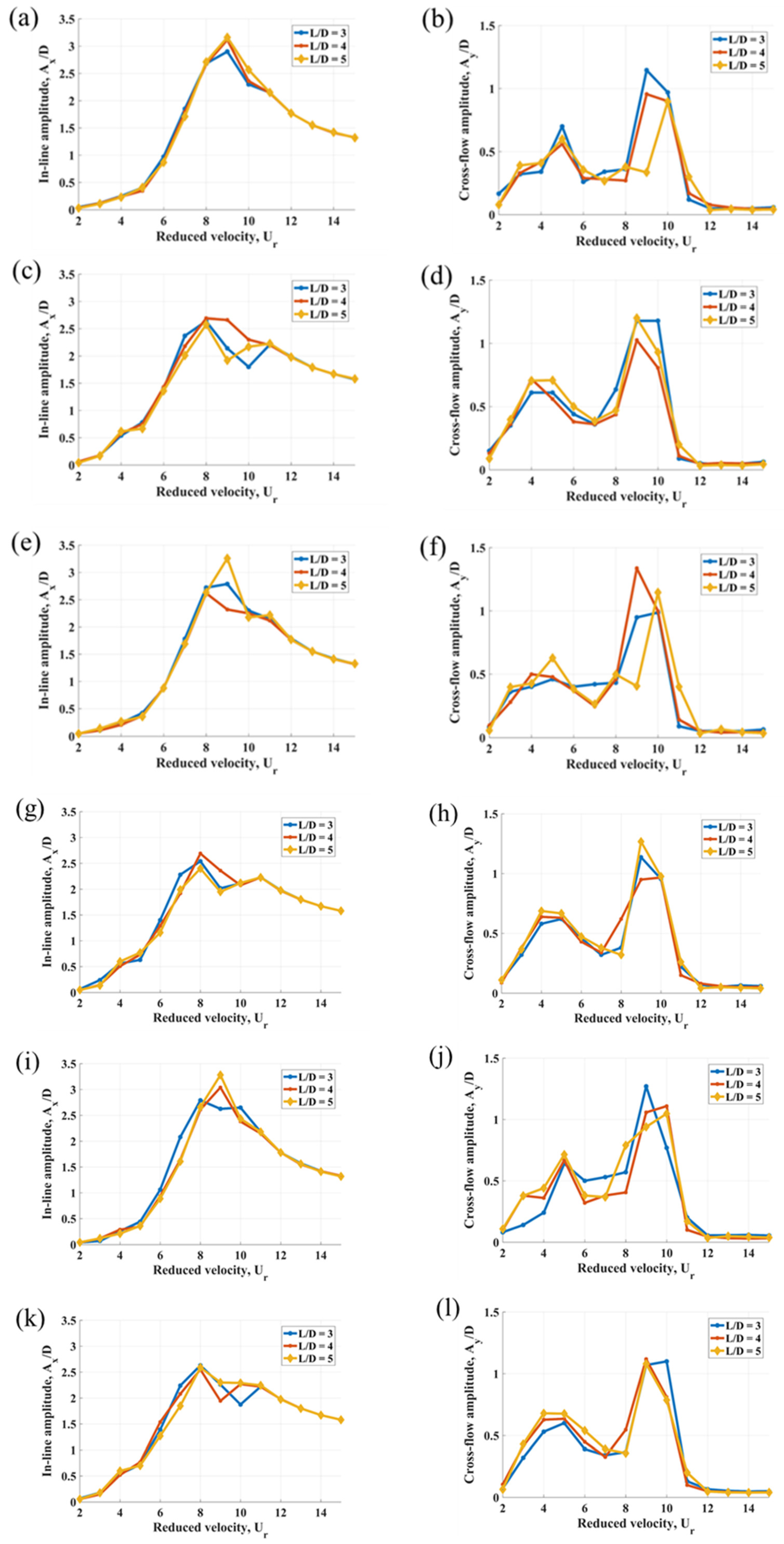
The spacing ratio plays a critical role in determining the vibration characteristics of the individual cylinders. Figure 7 presents the response amplitudes of the six cylinders as a function of reduced velocity for increasing . The maximum amplitudes summarised in Table 6 show a non-uniform dependence on spacing, indicating that each cylinder is strongly influenced by interactions with neighbouring wakes rather than behaving as an isolated structure.
Figure 7.
Maximum displacement amplitudes in: (a) the in-line direction for Cylinder 1; (b) the cross-flow direction for Cylinder 1; (c) the in-line direction for Cylinder 2; (d) the cross-flow direction for Cylinder 2; (e) the in-line direction for Cylinder 3; (f) the cross-flow direction for Cylinder 3. (g) the in-line direction for Cylinder 4; (h) the cross-flow direction for Cylinder 4; (i) the in-line direction for Cylinder 5; (j) the cross-flow direction for Cylinder 5; (k) the in-line direction for Cylinder 6; (l) the cross-flow direction for Cylinder 6.
Table 6.
Summary of the highest maximum displacement amplitudes of the considered structures.
As shown in Figure 7a, Cylinder 1 exhibits a monotonic increase in in-line vibration amplitude with increasing spacing ratio. The amplitude rises from at to 3.12 at , and further to 3.16 at . In contrast, the cross-flow amplitude in Figure 7b decreases steadily from at to 0.96 at and 0.90 at . This trend indicates that increasing spacing weakens vortex-induced synchronisation in the cross-flow direction. At smaller spacing (), strong wake interactions between neighbouring cylinders generate coherent alternating vortices, leading to enhanced lift forces and larger cross-flow oscillations.
Cylinder 2 displays a different behaviour. The in-line amplitude in Figure 7c increases slightly from at to 2.69 at , before decreasing to 2.58 at . The cross-flow amplitude in Figure 7d initially decreases from at to 1.03 at , followed by an increase to 1.20 at . The reduction at can be attributed to partial disruption of coherent vortex structures present at smaller spacing. As the spacing increases to , the wake has sufficient distance to reorganise, allowing more coherent vortices to develop and interact with Cylinder 2, thereby enhancing the cross-flow response.
Cylinder 3 shows pronounced sensitivity to spacing. Its cross-flow amplitude increases significantly from at to 1.34 at , before decreasing to 1.15 at . The in-line amplitude also increases from to 3.26 as the spacing increases from to 5. The peak cross-flow response at suggests that this intermediate spacing promotes favourable wake interaction. At this condition, vortices shed by upstream cylinders impinge on Cylinder 3 in a coherent manner, leading to strong synchronisation and amplified oscillations. With a further increase in spacing to , the wake structures lose coherence due to increased instability, reducing the effectiveness of periodic forcing and, consequently, the cross-flow amplitude.
Cylinder 4 exhibits a comparatively complex response. The in-line amplitude increases slightly from at to at , before decreasing to 2.40 at . In contrast, the cross-flow amplitude decreases from at to at , followed by a marked increase to at .
Because Cylinder 4 is located in the upstream region of the array, its response is primarily governed by direct interaction with the incoming oscillatory flow. However, neighbouring cylinders can still influence the local flow field through lateral interference and downstream wake feedback. At the smaller spacing ratio , the proximity of adjacent cylinders constrains the lateral development of the shear layers around Cylinder 4. This confinement can promote stronger vortex formation close to the cylinder surface, generating higher fluctuating lift forces and, consequently, a relatively large cross-flow response.
When the spacing increases to , the interaction between Cylinder 4 and its neighbours weakens. The reduced confinement allows the separated shear layers to develop more freely, which can diminish the coherence of the alternating vortex shedding responsible for cross-flow excitation. As a result, the fluctuating lift force decreases, leading to a reduction in cross-flow amplitude to .
A different behaviour of Cylinder 4 emerges when the spacing is further increased to . At this larger spacing, the influence of neighbouring cylinders becomes sufficiently weak, and Cylinder 4 behaves more like an isolated cylinder in oscillatory flow. Under these conditions, the vortex shedding process becomes more coherent and periodic, which can enhance the synchronisation between the fluid forcing and the structural response. The improved vortex coherence strengthens the fluctuating lift forces acting on the cylinder, leading to the observed increase in cross-flow amplitude to .
The in-line amplitude of Cylinder 4 follows a different trend, as the in-line motion is primarily driven by oscillatory drag forces rather than lift forces. The slight increase in between and suggests that drag oscillations intensify moderately as lateral confinement decreases. However, when the spacing is further increased to , the reduction in hydrodynamic interference from neighbouring cylinders leads to a decrease in overall drag fluctuation amplitude, resulting in a smaller in-line displacement.
Cylinder 5 exhibits a gradual increase in in-line amplitude with spacing, rising from at to at and reaching at . In contrast, the cross-flow amplitude decreases from at to at , and further to at . This behaviour indicates that Cylinder 5 gradually transitions towards a drag-dominated vibration regime as the spacing increases. At smaller spacing, strong vortex interactions between adjacent cylinders generate large fluctuating lift forces and, consequently, higher cross-flow amplitudes. As the spacing increases, these wake interactions weaken, reducing lift-induced oscillations while allowing drag-induced in-line motion to become more dominant.
Cylinder 6 exhibits the smallest variation with spacing. The in-line amplitude decreases slightly from at to at , before increasing marginally to at . The cross-flow amplitude remains nearly constant, varying only slightly from to , and then to .
This relatively stable response suggests that Cylinder 6 experiences weaker wake interference compared with the other cylinders. This occurs if its position within the array exposes it to a more balanced flow field, where vortical structures generated by neighbouring cylinders partially counteract one another. As a result, the hydrodynamic forcing acting on the cylinder remains relatively steady across the investigated spacing ratios.
Overall, the results demonstrate that increasing the spacing ratio does not produce a uniform response across the cylinder array. Instead, each cylinder responds differently depending on the local wake environment created by upstream bodies. At smaller spacing ratios, strong wake interactions generate coherent vortex structures that enhance cross-flow oscillations through lift-force synchronisation. As the spacing increases, wake interactions weaken for some cylinders but can become more organised for others, depending on the stability and development of the shed vortices.
Consequently, some cylinders exhibit reduced cross-flow vibration with increasing spacing, while others experience amplified responses due to constructive wake interactions. This non-uniform behaviour highlights the complex hydrodynamic coupling inherent in multi-cylinder systems subjected to oscillatory flow.
4.3. Frequency Ratios for the Individual Cylinders at the Increasing L/D Ratio
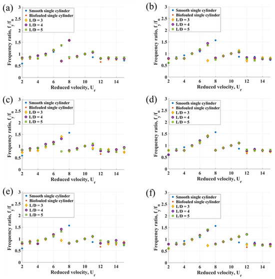
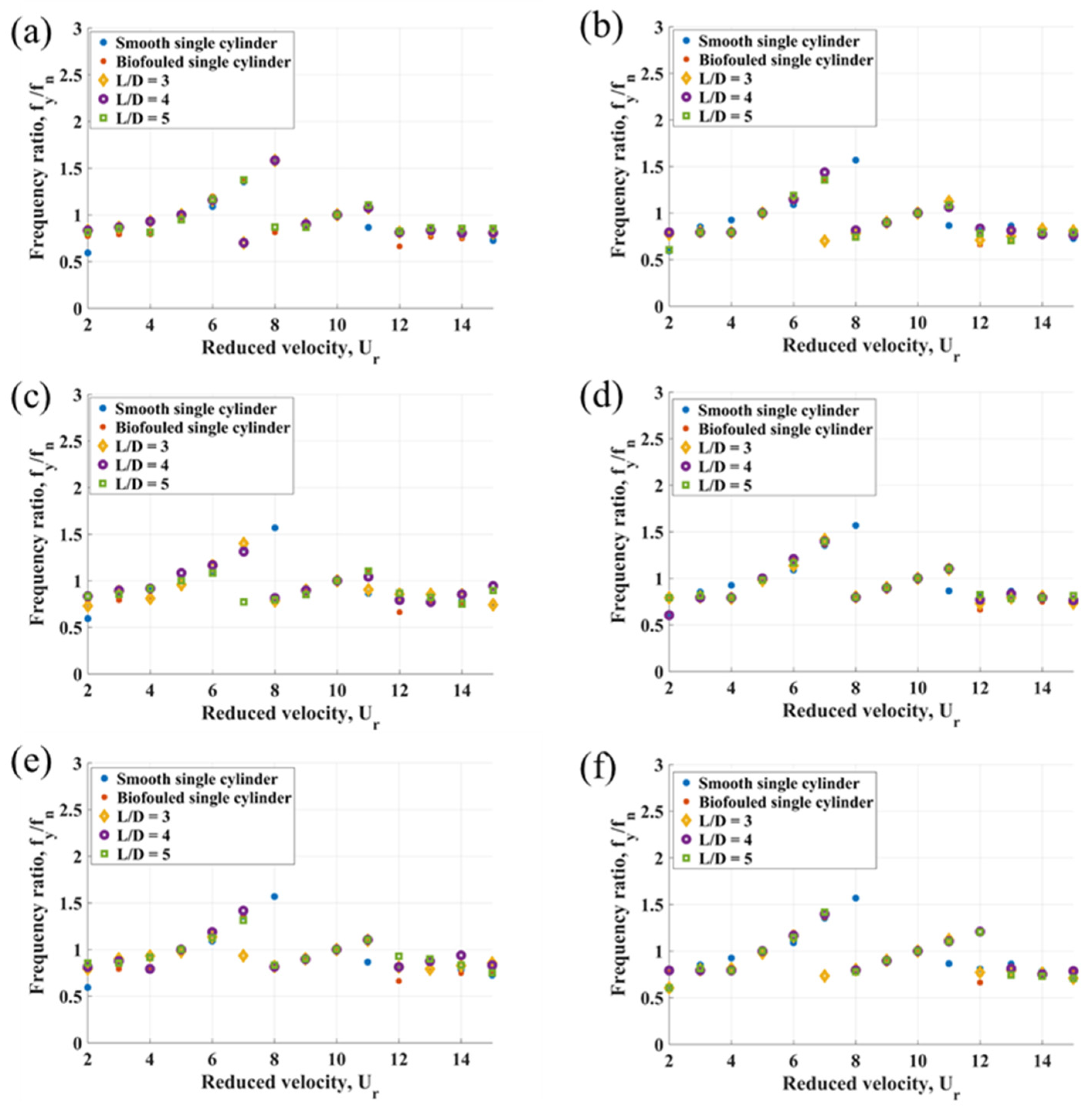
The frequency ratio , defined as the ratio between the structural vibration frequency and the natural frequency of the cylinder, provides key insight into the synchronisation between vortex shedding and structural motion. In addition, this study considers a second frequency ratio, , where is the oscillatory flow frequency. In vortex-induced vibration systems, large oscillation amplitudes typically occur when the vortex shedding frequency approaches the natural frequency of the structure. Within the lock-in regime, the vibration frequency remains close to the natural frequency over a range of reduced velocities.
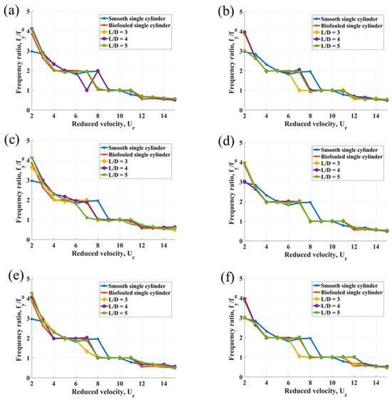
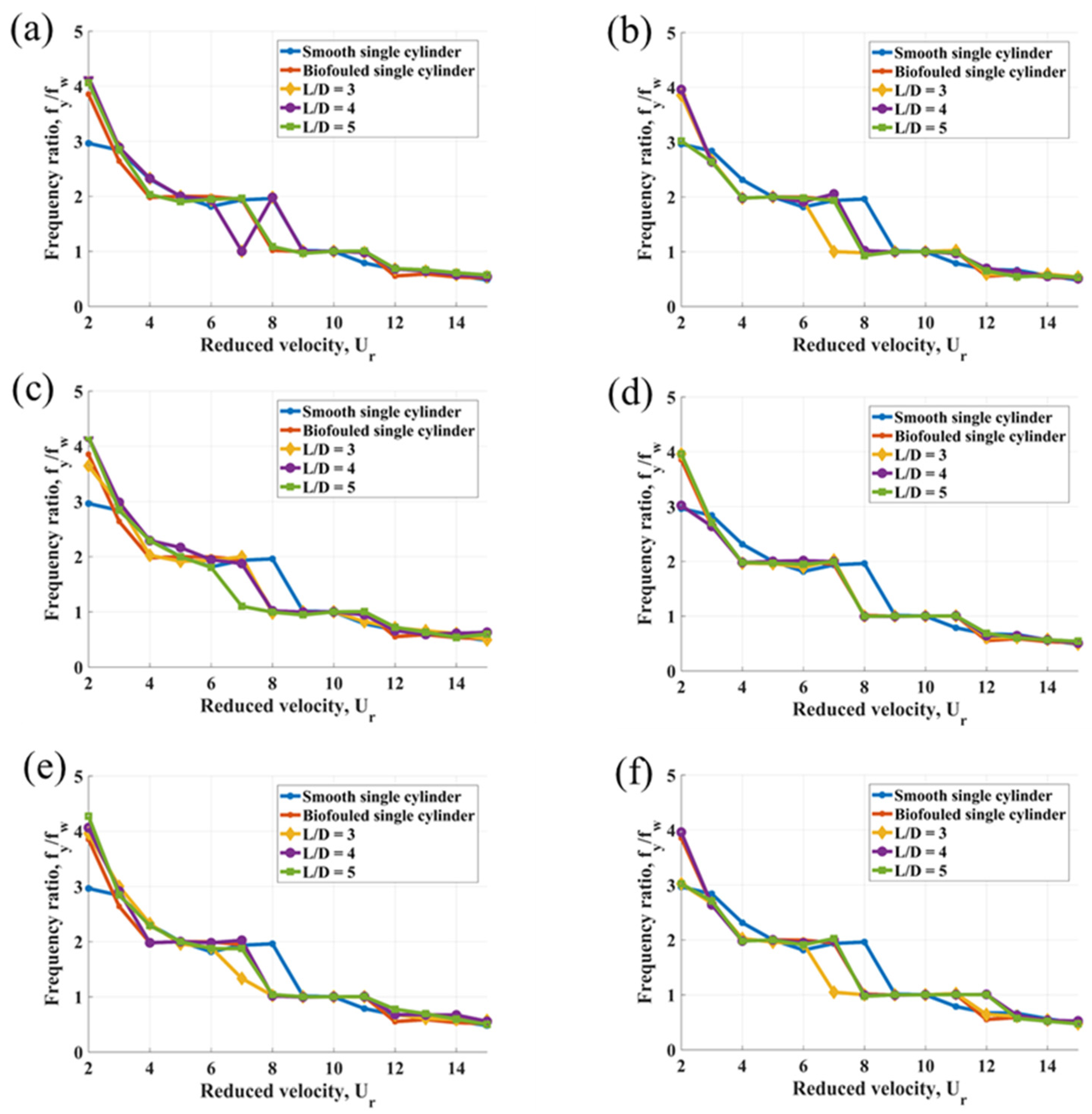
Figure 8 and Figure 9 present the frequency ratios for individual cylinders as a function of reduced velocity. To identify the dominant frequency components of the cross-flow response, a Fast Fourier Transform (FFT) analysis is applied. In oscillatory flow conditions, the fundamental flow frequency is given by . Consistent with previous studies [57,60], the present results show that, at a constant Keulegan–Carpenter number, the cross-flow vibration frequency decreases as the reduced velocity increases.
Figure 8.
Frequency ratio fy/fn for: (a) Cylinder 1; (b) Cylinder 2; (c) Cylinder 3; (d) Cylinder 4; (e) Cylinder 5; (f) Cylinder 6.
Figure 9.
Frequency ratio fy/fw for: (a) Cylinder 1; (b) Cylinder 2; (c) Cylinder 3; (d) Cylinder 4; (e) Cylinder 5; (f) Cylinder 6.
In the present study, the frequency ratio for both smooth and biofouled cylinders in Figure 8 approaches unity within the lock-in region, indicating that the structural oscillation becomes synchronised with the vortex shedding process. This behaviour is consistent with classical vortex-induced vibration theory, in which the transverse vibration frequency remains close to the natural frequency during lock-in. A comparison between smooth and biofouled cylinders shows a similar overall trend, although differences appear in the extent of the lock-in bandwidth. In general, biofouled cylinders exhibit slightly higher frequencies than smooth cylinders, consistent with [68].
Synchronisation is observed at reduced velocities of and for the investigated ratios. At , the cross-flow frequency coincides closely with the structural natural frequency. At , both the cross-flow vibration frequency and the oscillatory flow frequency align with the natural frequency, as shown in Figure 7 and Figure 8. In the intermediate range , Figure 8 indicates a temporary lock-out, where the vibration frequency increases between two synchronised states while the displacement amplitudes decrease, as discussed previously. This range also reveals a relative shift between the transverse vibration frequency and the oscillatory flow frequency for each cylinder in Figure 9. These two features—transition between frequency modes and lock-out—lead to fluctuations in cross-flow amplitude between successive peaks.
Previous studies [54,69,70] have shown that cross-flow vibrations in pure oscillatory flow often occur at frequencies that are integer multiples of the flow frequency. As defined in [68], a single-frequency mode corresponds to vibration at the flow frequency, while a double-frequency mode corresponds to vibration at twice the flow frequency.
The present results, illustrated in Figure 9, reveal the following mode transitions. For Cylinder 1 at and , the response shifts from a double-frequency mode at to a single-frequency mode at , then returns to a double-frequency mode at , before reverting again to a single-frequency mode at . At , Cylinder 1 exhibits a double-frequency mode at and , and transitions to a single-frequency mode for .
For Cylinder 2, at , a transition from double-frequency behaviour at to single-frequency behaviour at is observed. At , the system exhibits double-frequency behaviour at and single-frequency behaviour at , while at the transition occurs from double-frequency behaviour at to single-frequency behaviour at .
For Cylinder 3, a double-frequency mode is observed at for and at for , while a single-frequency mode is maintained at for all spacing ratios. At , Cylinder 4 transitions from a double-frequency mode at to a single-frequency mode at .
At , Cylinder 5 also exhibits a transition from a double-frequency mode at to a single-frequency mode at .
For Cylinder 6, at , a shift from a double-frequency mode at to a single-frequency mode at is observed. At and , the response similarly transitions from a double-frequency mode at to a single-frequency mode at .
4.4. XY Trajectories for Cylinders 1 and 2 at the Increasing L/D Ratio
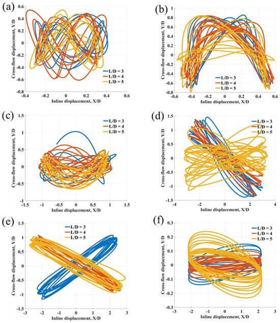
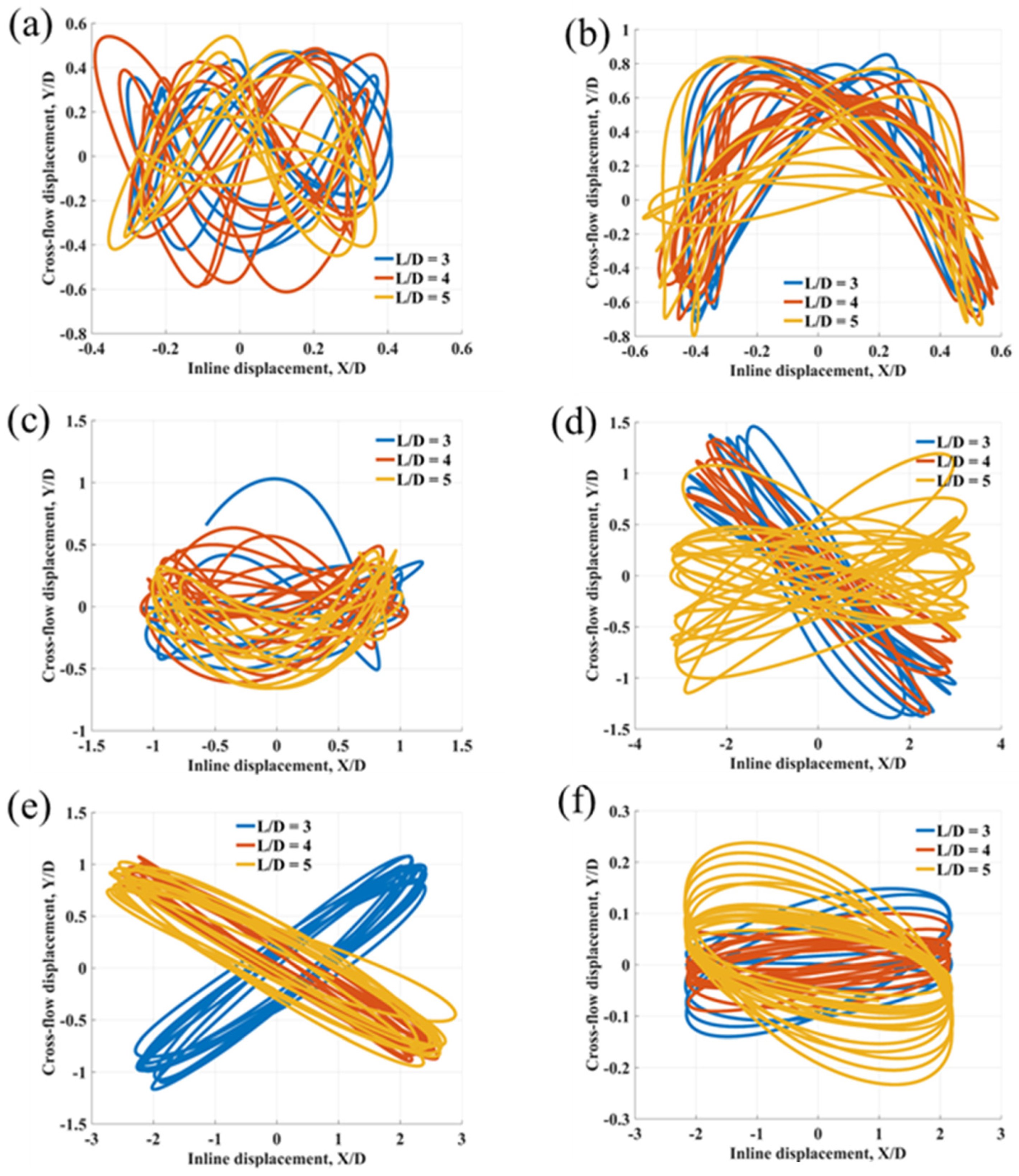
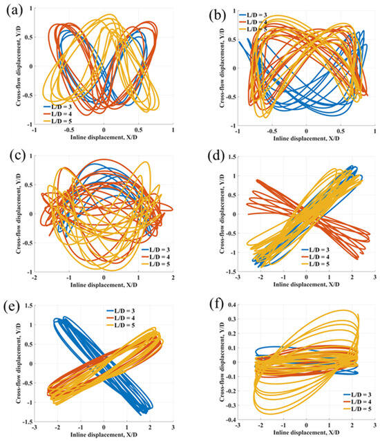
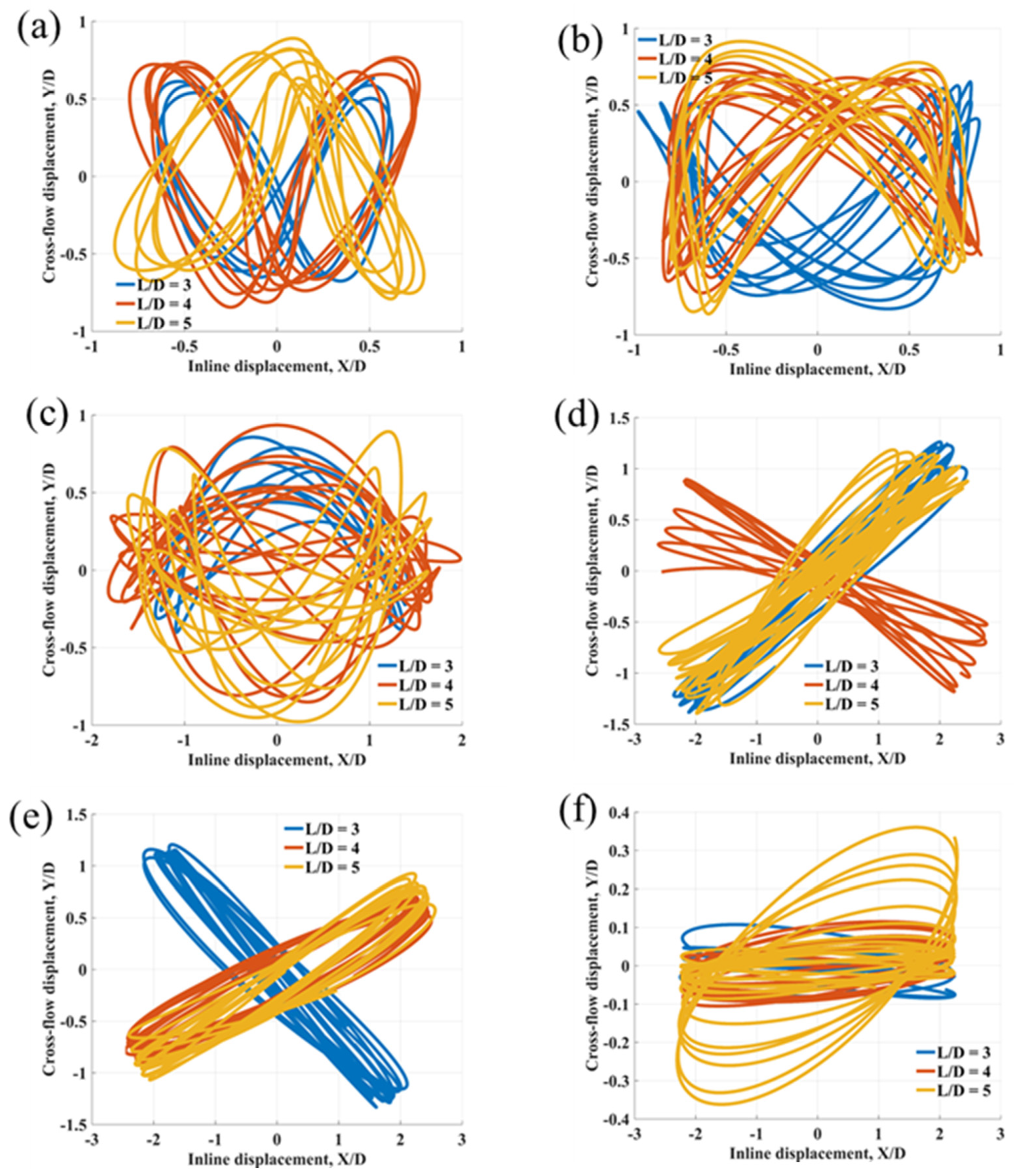
Figure 10 and Figure 11 illustrate the XY motion of Cylinders 1 and 2 at selected reduced velocities for the investigated ratios. Trajectories of other structures do not differ qualitatively from Cylinders 1 and 2. The XY trajectories provide detailed insight into the lock-in regimes and the associated vibration modes induced by the oscillatory flow and cylinder–cylinder interference.
Figure 10.
XY trajectories of Cylinder 1 at: (a) = 4; (b) = 5; (c) = 6; (d) = 9; (e) = 10; (f) = 11.
Figure 11.
XY trajectories of Cylinder 2 at: (a) = 4; (b) = 5; (c) = 6; (d) = 9; (e) = 10; (f) = 11.
At for all considered ratios, the cylinders exhibit a well-defined figure-of-eight pattern, which is characteristic of vortex-induced vibration lock-in for a two-degree-of-freedom rigid structure in oscillatory flow. In this condition, the vibration frequency matches the structural natural frequency () and is approximately twice the flow frequency (), corresponding to a double-frequency mode, as discussed in the previous subsection.
Within the reduced velocity range , the motion of Cylinders 1 and 2 becomes increasingly irregular. The trajectories gradually transition from organised patterns to distorted shapes, including elongated loops and multi-loop structures. At , the cylinders exhibit a distinct arc-shaped trajectory, indicating a single-frequency mode in which the vibration frequency synchronises with the oscillatory flow frequency. The motion is characterised by relatively large in-line and cross-flow displacements, forming an elliptic orbit approaching a near-linear response in certain phases.
At , a ring-like or oval-shaped trajectory is observed, marking a transitional state preceding the in-line-dominated response at , where cross-flow vibrations begin to diminish significantly.
4.5. Vorticity Magnitude
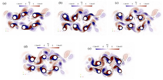
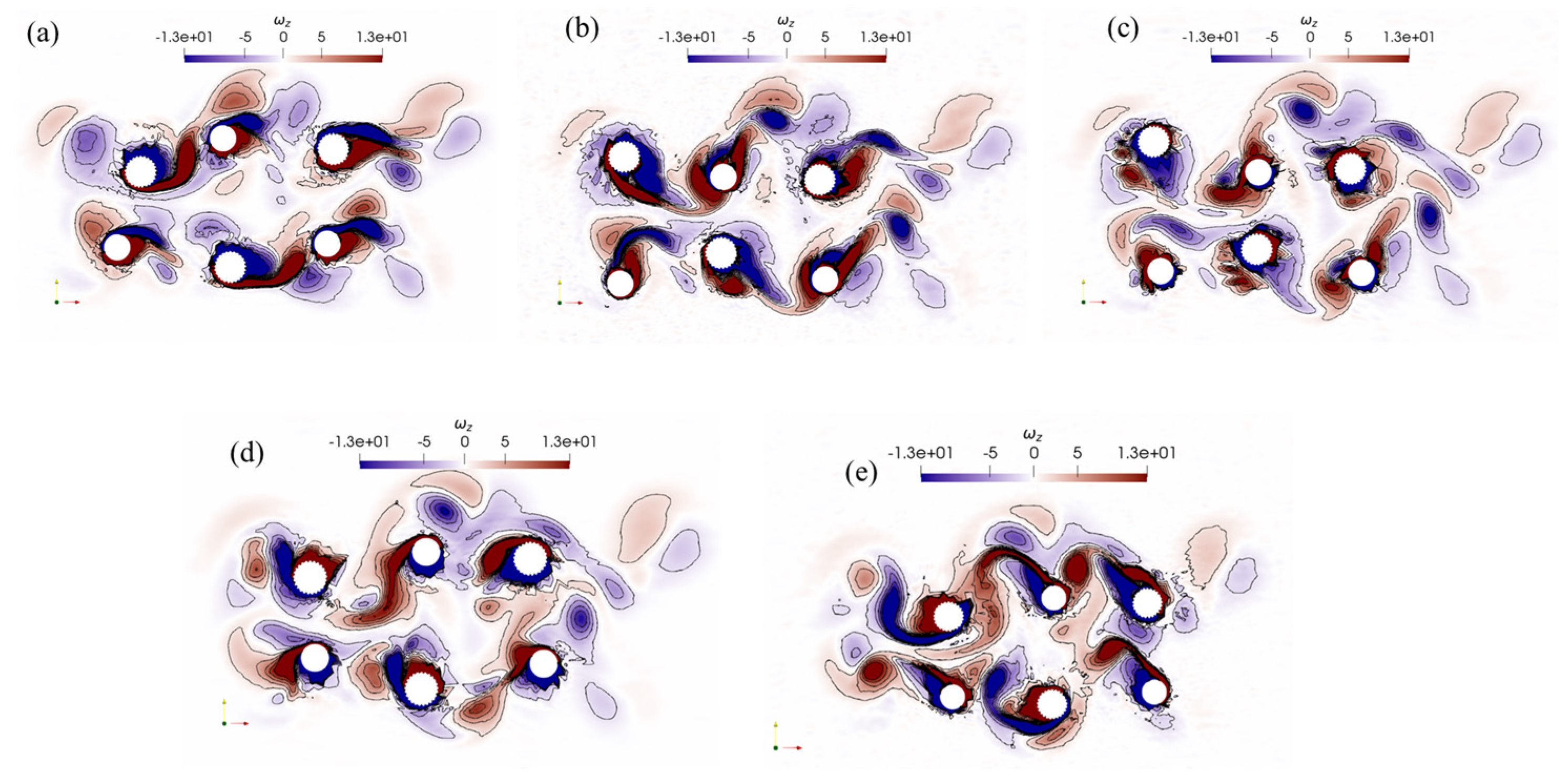
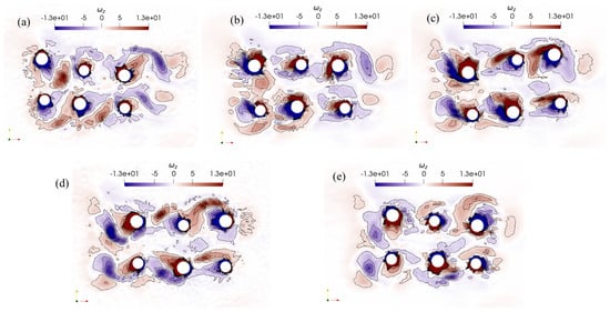
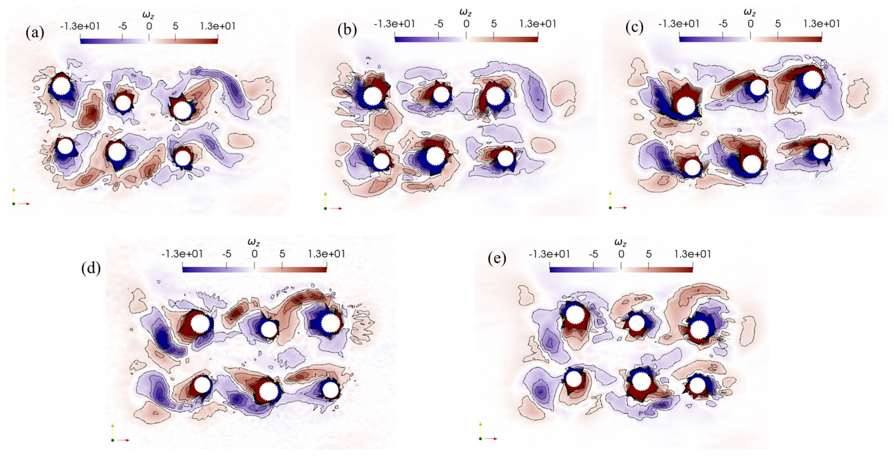
Figure 12 shows the vorticity field around the six-cylinder array with partial biofouling at and a reduced velocity of . This value lies within the lock-in regime identified previously, where the cross-flow vibration frequency synchronises with the structural natural frequency in a double-frequency mode.
Figure 12.
Vorticity magnitude contour for L/D = 4 at = 5 within one oscillatory flow period at the time of: (a) 3.5 s; (b) 3.755 s; (c) 4.0 s; (d) 4.215 s; (e) 4.5 s.
At the early stage of the oscillation cycle (Figure 12), the wake is characterised by relatively organised vortex shedding from individual cylinders. Distinct alternating vortices of opposite sign form near the shear layers, particularly for cylinders directly exposed to the incoming flow. This suggests that, at this stage, the flow retains a degree of spatial coherence, and vortex formation is still largely governed by local boundary-layer separation rather than strong inter-cylinder interference. However, even at this early instant, deviations from a classical Kármán vortex street are already evident. The proximity of neighbouring cylinders disrupts the symmetry of vortex formation, so that instead of a regular staggered pattern, vortices interact shortly after shedding, leading to partial merging and deformation of the wake structures.
As the flow evolves within the same oscillation cycle, the wake becomes increasingly complex. The later snapshots in Figure 13 show a marked loss of coherence, with the vorticity field populated by a mixture of small- and large-scale structures, indicating intensified vortex interaction, breakdown, and reorganisation. This transition is driven by strong wake–wake interactions inherent to the multi-cylinder configuration, where vortices shed from upstream cylinders, convect downstream and impinge on neighbouring bodies, either enhancing or suppressing local vortex formation.
Figure 13.
Vorticity magnitude contour for L/D = 4 at = 5 within one oscillatory flow period at the time of: (a) 20.6 s; (b) 20.84 s; (c) 21.07 s; (d) 21.29 s; (e) 21.6 s.
Despite the apparent disorder at later stages, the flow does not become fully irregular. The persistence of alternating-sign vorticity structures in the vicinity of the cylinders indicates that vortex shedding remains phase-locked with the structural motion. This is consistent with the lock-in condition observed in the amplitude and frequency responses. The observed disorganisation therefore reflects increased spatial complexity rather than a loss of synchronisation.
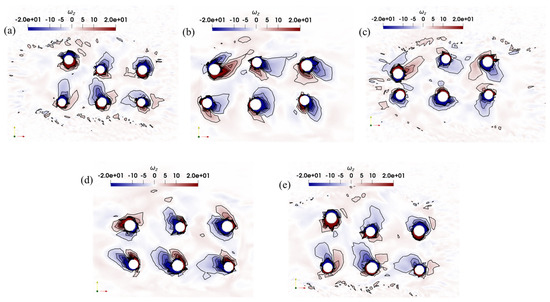
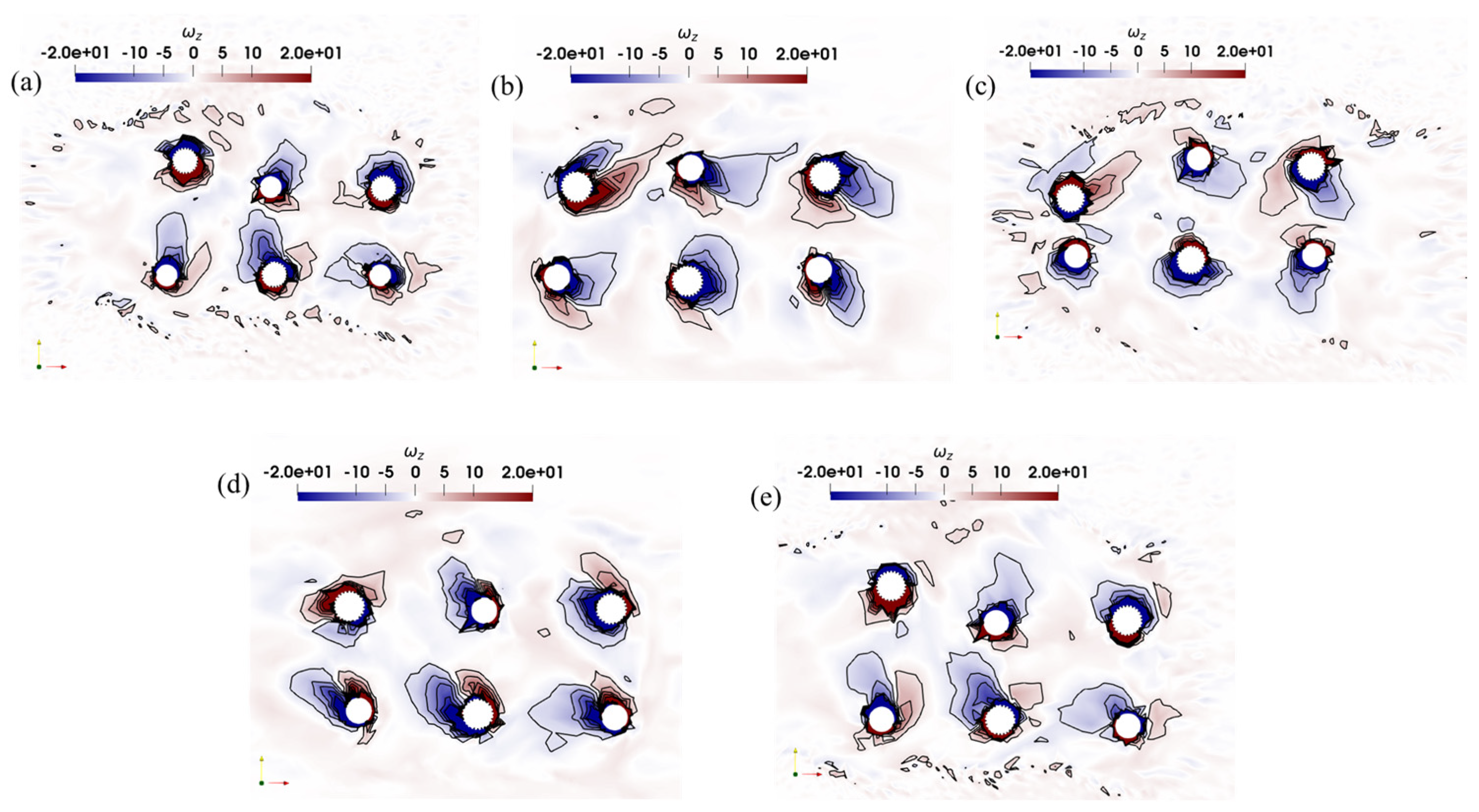
Figure 14 shows the vorticity field at and a reduced velocity of . This flow condition corresponds to the upper limit of the lock-in regime identified previously and is associated with a transition toward a single-frequency response mode, where the vibration frequency synchronises with both the flow oscillation frequency and the structural natural frequency. In this regime, the motion becomes dominated by large in-line displacements.
Figure 14.
Vorticity magnitude contour for L/D = 5 at = 10 within one oscillatory flow period at the time of: (a) 19.4 s; (b) 19.6 s; (c) 19.8 s; (d) 20.0 s (e) 20.2 s.
Compared with Figure 12 and Figure 13, the vorticity structures appear more elongated and diffuse, rather than compact and well-defined. This reflects a reduction in the strong constructive wake interactions observed at smaller spacing. At , the increased separation allows the wakes of upstream cylinders more space to develop before interacting with downstream bodies. However, instead of promoting stronger coherent structures, the vortices progressively weaken and lose coherence as they convect downstream, indicating that wake dynamics are increasingly governed by oscillatory flow acceleration and reversal rather than inter-cylinder interference.
Unlike the well-defined alternating vortex shedding observed at , the shear layers at tend to elongate downstream before rolling up into vortical structures. The effect of increased spacing is also evident: while interaction between cylinders is reduced, the vortices do not organise into more coherent patterns but instead exhibit progressive diffusion and decay.
Notably, there is no clear formation of a classical Kármán vortex street behind individual cylinders. Instead, the wake is characterised by intermittent and asymmetric vorticity patches, reflecting the strong influence of oscillatory flow reversal. As the flow direction changes within each cycle, previously shed vortices are stretched, weakened, or partially reabsorbed by the surrounding flow field. This continuous reorganisation inhibits the development of a stable, periodic shedding pattern.
5. Limitations, Future Work and Practical Applications
The present study is constrained by several aspects of the numerical configuration. The results are strictly valid within the parameter range investigated, specifically for Reynolds numbers between 955 and 7166, the mass ratio of 1.62, and the damping ratio of 0.0, all of which strongly influence the vortex-induced vibration behaviour. In addition, the analysis considers only the fixed T/D = 4 and three spacing ratios of L/D = 3, 4 and 5. Consequently, applying these findings to different flow or structural conditions should be approached with caution and would normally require additional simulations for verification. The adopted modelling strategy also reduces the inherently three-dimensional fluid–structure interaction problem to a two-dimensional RANS model. This simplification is supported by the validation against previously published results. Furthermore, biofouling is represented using an idealised configuration of uniformly distributed triangular elements based on earlier studies, including [35], whereas natural marine fouling typically occurs in irregular and non-uniform patterns. It should be noted that the current study does not consider alternative coverage ratios, as appears in [71]. This means that if not fully biofouled structures are in place of fully biofouled objects investigated in the present work, the dynamic response during the lock-in state could be significantly altered or reduced, also affecting wake interactions with bare objects in the six-cylinder array. Additionally, changes in the structural mass related to full biofouling are not accounted for, so that only the effects of changes in the volume and geometrical shape of the cross-section are observed in the current results. The assumption of the constant added mass coefficient also leads to a simplified description of inertial effects, affecting reported response amplitudes and frequencies. Another assumption of the zero damping leads to some overestimation of response amplitudes, which is supported by the practical necessity to account for the dynamics in the worst-case scenario.
These limitations also point to several promising directions for future research. One natural extension would be to perform fully three-dimensional simulations using higher-fidelity approaches such as Large Eddy Simulation (LES) or hybrid turbulence modelling techniques, in order to resolve more detailed wake dynamics and turbulence–structure interactions. Since the present study focuses on a specific combination of flow and structural parameters, future work should also explore a broader range of spacing ratios ( and ), variations in structural properties such as mass and damping ratios, an increased number of cylinders in the array, different inflow conditions, and alternative distributions of smooth and biofouled cylinders. Such investigations would provide a more comprehensive understanding of their combined influence on lock-in behaviour and overall vortex-induced vibration response.
In practical offshore applications, multiple pipelines are often installed in parallel bundles to reduce installation costs. In such configurations, hydrodynamic interference between neighbouring pipes becomes a key concern. The spacing ratio between cylinders strongly governs wake interaction and, consequently, the vibration response. Studying multi-cylinder arrangements with varying spacing ratios can therefore provide valuable insight into how pipeline spacing affects VIV, helping to define safe separation distances that minimise vibration amplification due to wake interference.
Vertical risers transporting hydrocarbons from the seabed to floating production platforms are also cylindrical structures exposed to oscillatory wave- and current-induced flows. Marine growth is commonly observed on these structures, and the resulting surface roughness can significantly modify vortex shedding behaviour. Understanding how roughness affects vibration frequency and amplitude is therefore essential for reliable fatigue assessment. Excessive VIV can lead to long-term fatigue damage and eventual structural failure. Based on the predicted vibration amplitudes in both in-line and cross-flow directions, the present results suggest that configurations with six partially biofouled cylinders operating at reduced velocities below the lock-in regime (around ) are more favourable, whereas operation above the lock-in region leads to significantly amplified in-line responses.
6. Conclusions
This study numerically investigates the vortex-induced vibration of six elastically mounted, two-degree-of-freedom circular cylinders, three smooth and three biofouled. The array is subjected to oscillatory flow at a constant Keulegan–Carpenter number of . The main objective is to examine the influence of the longitudinal spacing ratio ( and ) on the vibration response in the lock-in regime, including vibration amplitudes, frequency ratios, trajectory patterns, and vortex dynamics, while the transverse spacing ratio is kept fixed at .
The key findings of this work are as follows:
- The cross-flow vibration amplitudes for both isolated and grouped cylinders exhibit a clear lock-in regime within the reduced velocity range . Biofouled cylinders generally attain higher peak cross-flow amplitudes than smooth cylinders at specific reduced velocities (e.g., ), supporting previous observations that surface roughness can enhance oscillatory responses under certain flow conditions. In-line vibration amplitudes become dominant for .
- The spacing ratio is found to significantly influence the response of individual cylinders. No single configuration is optimal for all cylinders, as the peak amplitudes are strongly dependent on each cylinder’s position within the array and the prevailing flow regime. The highest displacement amplitudes occur at different reduced velocities for biofouled structures compared with smooth ones, with biofouled cylinders generally reaching their peak response earlier in the reduced velocity range. This highlights the strong role of wake interference and fluid–structure interaction within the array.
- Frequency analysis reveals two key synchronisation points at and . At , the cross-flow vibration frequency synchronises with the structural natural frequency, corresponding to a double-frequency mode relative to the flow. At , synchronisation occurs with the oscillatory flow frequency, indicating a single-frequency mode. The transition between these regimes in the range is characterised by irregular amplitude fluctuations.
- The XY trajectories provide clear visual evidence of lock-in behaviour. A well-defined figure-of-eight pattern, characteristic of two-degree-of-freedom lock-in in the double-frequency mode, is observed at . At higher reduced velocities (), the trajectories evolve into arc-like shapes, indicating a single-frequency mode dominated by strong in-line motion. For , the motion becomes predominantly in-line as cross-flow oscillations diminish.
In summary, this numerical study demonstrates that both biofouling and the longitudinal spacing ratio are key parameters governing the vortex-induced vibration response of multi-cylinder arrays in oscillatory flow. These effects give rise to complex, non-uniform response patterns across the array, with important implications for the design and fatigue assessment of offshore structures such as pipelines and risers, where multi-body interference and marine growth are commonly encountered. The results provide new insight into lock-in behaviour, mode transitions, and the coupled fluid–structure interaction of rough cylinders in close proximity.
Author Contributions
Conceptualization, methodology, formal analysis, investigation, validation, data curation, visualisation, writing—original draft preparation, H.F.A.; writing—original draft preparation, writing—review and editing, supervision, funding acquisition, project administration, V.K. All authors have read and agreed to the published version of the manuscript.
Funding
Authors would like to acknowledge the support of the Ministry of Science and Higher Education of the Russian Federation, grant number FEWN-2024-0005.
Data Availability Statement
The results are provided within the article.
Conflicts of Interest
The authors declare no conflicts of interest.
References
- Sparks, C. Fundamentals of Marine Riser Mechanics: Basic Principles and Simplified Analyses; PennWell Books, LLC: Tulsa, OK, USA, 2018; Available online: https://books.google.ru/books/about/Fundamentals_of_Marine_Riser_Mechanics.html?id=SrcfEAAAQBAJ&redir_esc=y (accessed on 20 March 2026).
- Blevins, R.D. Flow-Induced Vibration; Elsevier: New York, NY, USA, 1977; Available online: https://books.google.ru/books/about/Flow_induced_Vibration.html?id=yJ9RAAAAMAAJ&redir_esc=y (accessed on 20 March 2026).
- Griffin, O.M. Vortex-Induced Vibrations of Marine Cables and Structures; Naval Research Laboratory: Washington, DC, USA, 1985. Available online: https://www.bsee.gov/sites/bsee.gov/files/tap-technical-assessment-program//074af.pdf (accessed on 20 March 2026).
- DNV. DNV-RP-F204 Riser Fatigue; Recommended Practice; DNV: Hovik, Norway, 2005; Available online: https://www.dnv.com/energy/standards-guidelines/dnv-rp-f204-riser-fatigue/ (accessed on 20 March 2026).
- Harandi, M.A.; Tamimi, V.; Zeinoddini, M.; Rashki, M.R.; Ashrafipour, H. Effects of soft marine growth on vortex-induced vibration: A comparative analysis with hard marine growth. Appl. Ocean Res. 2024, 144, 103906. [Google Scholar] [CrossRef] [Scilit]
- Terry, L.A.; Picken, G.B. Algal fouling in the North Sea. In Studies in Environmental Science; Elsevier: Amsterdam, The Netherlands, 1986; Volume 28, pp. 179–192. [Google Scholar] [CrossRef] [Scilit]
- Kokabi, M.; Yousefzadi, M. Checklist of the marine macroalgae of Iran. Bot. Mar. 2015, 58, 307–320. [Google Scholar] [CrossRef] [Scilit]
- Williamson, C.H.; Govardhan, R. Vortex-induced vibrations. Annu. Rev. Fluid Mech. 2004, 36, 413–455. [Google Scholar] [CrossRef] [Scilit]
- Sarpkaya, T. A critical review of the intrinsic nature of vortex-induced vibrations. J. Fluids Struct. 2004, 19, 389–447. [Google Scholar] [CrossRef]
- Gabbai, R.D.; Benaroya, H. An overview of modeling and experiments of vortex-induced vibration of circular cylinders. J. Sound Vib. 2005, 282, 575–616. [Google Scholar] [CrossRef] [Scilit]
- Stappenbelt, B.; Lalji, F.; Tan, G. Low mass ratio vortex-induced motion. In Proceedings of the 16th Australasian Fluid Mechanics Conference, Crown Plaza, Gold Coast, Australia, 2–7 December 2007; Available online: https://people.eng.unimelb.edu.au/imarusic/proceedings/16/Stappenbelt.pdf (accessed on 20 March 2026).
- Stappenbelt, B.; Lalji, F. Vortex-induced vibration super-upper response branch boundaries. Int. J. Offshore Polar Eng. 2008, 18, 99–105. Available online: https://onepetro.org/IJOPE/article-abstract/29312/Vortex-induced-Vibration-Super-Upper-Response (accessed on 20 March 2026).
- Blevins, R.D.; Coughran, C.S. Experimental investigation of vortex-induced vibration in one and two dimensions with variable mass, damping, and Reynolds number. J. Fluids Eng. 2009, 131, 101202. [Google Scholar] [CrossRef] [Scilit]
- Annapeh, H.F.; Kurushina, V. VIV of 2DOF square and 1DOF circular structures in tandem. Mech. Res. Commun. 2025, 146, 104423. [Google Scholar] [CrossRef] [Scilit]
- Annapeh, H.F.; Kurushina, V. Hydrodynamic loads on a group of six structures of different cross-sections in uniform and sheared flow. J. Mar. Sci. Eng. 2023, 11, 383. [Google Scholar] [CrossRef] [Scilit]
- Annapeh, H.F.; Kurushina, V.; Franzini, G.R. Flow-Induced Vibrations of Five Cylinders in Uniform Current. Vibration 2025, 8, 31. [Google Scholar] [CrossRef] [Scilit]
- Annapeh, H.F.; Kurushina, V. Transversal vortex-induced vibration of a circular cylinder in tandem with a stationary square structure. Appl. Mech. 2024, 5, 978–996. [Google Scholar] [CrossRef] [Scilit]
- Annapeh, H.F.; Kurushina, V. Linear Sheared Flow Effects in Vortex-Induced Forces on Three Tandem Subsea Structures in Proximity to Larger Objects. In Advances in Nonlinear Dynamics, Volume I; Springer Nature: Cham, Switzerland, 2023. [Google Scholar] [CrossRef] [Scilit]
- Annapeh, H.F.; Kurushina, V. Flow-Induced Vibrations of a Square Cylinder in the Combined Steady and Oscillatory Flow. J. Mar. Sci. Eng. 2025, 13, 1621. [Google Scholar] [CrossRef] [Scilit]
- Keulegan, G.H.; Carpenter, L.H. Forces on cylinders and plates in an oscillating fluid. J. Res. Natl. Bur. Stand. 1958, 60, 423–440. Available online: https://books.google.ru/books?hl=en&lr=&id=n1MXAQAAMAAJ&oi=fnd&pg=PA423&ots=LalrRk2l3P&sig=nBkKP-Yv5PQjH07HC3giF1sttjs&redir_esc=y#v=onepage&q&f=false (accessed on 20 March 2026). [CrossRef] [Scilit]
- Williamson, C.H.K. Sinusoidal flow relative to circular cylinders. J. Fluid Mech. 1985, 155, 141–174. [Google Scholar] [CrossRef] [Scilit]
- Barbi, C.; Favier, D.P.; Maresca, C.A.; Telionis, D.P. Vortex shedding and lock-on of a circular cylinder in oscillatory flow. J. Fluid Mech. 1986, 170, 527–544. [Google Scholar] [CrossRef] [Scilit]
- Ren, H.; Zhang, M.; Wang, Y.; Xu, Y.; Fu, S.; Fu, X.; Zhao, B. Drag and added mass coefficients of a flexible pipe undergoing vortex-induced vibration in an oscillatory flow. Ocean Eng. 2020, 210, 107541. [Google Scholar] [CrossRef] [Scilit]
- Zhao, M. Numerical investigation of two-degree-of-freedom vortex-induced vibration of a circular cylinder in oscillatory flow. J. Fluids Struct. 2013, 39, 41–59. [Google Scholar] [CrossRef] [Scilit]
- Bushnell, M.J. Forces on cylinder arrays in oscillating flow. In Proceedings of the Offshore Technology Conference, Houston, TX, USA, 2–5 May 1977. [Google Scholar] [CrossRef] [Scilit]
- Skomedal, N.G.; Vada, T.; Sortland, B. Viscous forces on one and two circular cylinders in planar oscillatory flow. Appl. Ocean Res. 1989, 11, 114–134. [Google Scholar] [CrossRef] [Scilit]
- An, H.W.; Cheng, L.; Zhao, M.; Dong, G.H. Numerical simulation of the oscillatory flow around two cylinders in tandem. J. Hydrodyn. 2006, 18, 189–195. [Google Scholar] [CrossRef] [Scilit]
- Chern, M.J.; Kanna, P.R.; Lu, Y.J.; Cheng, I.C.; Chang, S.C. A CFD study of the interaction of oscillatory flows with a pair of side-by-side cylinders. J. Fluids Struct. 2010, 26, 626–643. [Google Scholar] [CrossRef] [Scilit]
- Zhao, M.; Cheng, L. Two-dimensional numerical study of vortex shedding regimes of oscillatory flow past two circular cylinders in side-by-side and tandem arrangements at low Reynolds numbers. J. Fluid Mech. 2014, 751, 1–37. [Google Scholar] [CrossRef] [Scilit]
- Lu, L.; Zhou, Z.; Zhang, C. Flow regime identification and flow instability analysis of oscillatory flows over twin circular cylinders. Phys. Fluids 2023, 35, 103601. [Google Scholar] [CrossRef] [Scilit]
- An, H.; Cheng, L.; Zhao, M.; Dong, G. Numerical simulation of oscillatory flow around two circular cylinders of different diameters. In Proceedings of the 25th International Conference on Offshore Mechanics and Arctic Engineering, Hamburg, Germany, 4–9 June 2006. [Google Scholar] [CrossRef] [Scilit]
- Pearcey, T.; Zhao, M.; Xiang, Y.; Liu, M. Vibration of two elastically mounted cylinders of different diameters in oscillatory flow. Appl. Ocean Res. 2017, 69, 173–190. [Google Scholar] [CrossRef] [Scilit]
- Tong, F.; Cheng, L.; Zhao, M.; An, H. Oscillatory flow regimes around four cylinders in a square arrangement under small KC and Re conditions. J. Fluid Mech. 2015, 769, 298–336. [Google Scholar] [CrossRef] [Scilit]
- Ren, C.; Cheng, L.; Tong, F.; Xiong, C.; Chen, T. Oscillatory flow regimes around four cylinders in a diamond arrangement. J. Fluid Mech. 2019, 877, 955–1006. [Google Scholar] [CrossRef] [Scilit]
- Annapeh, H.F.; Kurushina, V. Vortex-Induced Vibrations of a 2DOF Rigid Cylinder with Hard Marine Growth in Turbulent Oscillatory Flow. Fluids 2026, 11, 55. [Google Scholar] [CrossRef] [Scilit]
- Ashrafipour, H.; Zeinoddini, M.; Tamimi, V.; Rashki, M.R.; Jadidi, P. Two-degrees-of-freedom vortex-induced vibration of cylinders covered with hard marine fouling. Int. J. Mech. Sci. 2022, 233, 107624. [Google Scholar] [CrossRef] [Scilit]
- Bakhtiari, A.; Zeinoddini, M.; Ashrafipour, H.; Tamimi, V.; Harandi, M.A.; Jadidi, P. The effects of marine fouling on the wake-induced vibration of tandem circular cylinders. Ocean Eng. 2020, 216, 108093. [Google Scholar] [CrossRef] [Scilit]
- Jadidi, P.; Zeinoddini, M. Influence of hard marine fouling on energy harvesting from Vortex-Induced Vibrations of a single-cylinder. Renew. Energy 2020, 152, 516–528. [Google Scholar] [CrossRef] [Scilit]
- Rashki, M.R.; Hejazi, K.; Tamimi, V.; Zeinoddini, M.; Ashrafipour, H. Impacts of hard marine growth on 2DoF VIV-based piezoelectric energy harvesting. Renew. Energy 2024, 231, 120913. [Google Scholar] [CrossRef] [Scilit]
- Zhao, H.; Yin, Y.; Gao, P.; Tian, R.; Li, X.; Tan, S. Numerical studies on the effect of surface roughness on flow field and flow-induced vibration in the in-line tube bundle. Nucl. Eng. Des. 2024, 424, 113313. [Google Scholar] [CrossRef] [Scilit]
- Zdravkovich, M.M. Review of Flow Interference Between Two Circular Cylinders in Various Arrangements. J. Fluids Eng. 1977, 99, 618–633. [Google Scholar] [CrossRef] [Scilit]
- Assi, G.R.D.S.; Bearman, P.W.; Meneghini, J.R. On the wake-induced vibration of tandem circular cylinders: The vortex interaction excitation mechanism. J. Fluid Mech. 2010, 661, 365–401. [Google Scholar] [CrossRef] [Scilit]
- Lin, K.; Sun, Y.; Liu, H.; Zhu, Y.; Wang, J.; Triantafyllou, M.S.; Fan, D. Mapping the properties of wake-induced vibration on a circular cylinder. J. Fluid Mech. 2024, 1001, A33. [Google Scholar] [CrossRef] [Scilit]
- Kim, S.; Alam, M.M.; Sakamoto, H.; Zhou, Y. Flow-induced vibrations of two circular cylinders in tandem arrangement. Part 1: Characteristics of vibration. J. Wind Eng. Ind. Aeodyn. 2009, 97, 304–311. [Google Scholar] [CrossRef] [Scilit]
- Caraeni, D.; Modarres-Sadeghi, Y. Collective Behavior of Clusters of Free-to-Move Cylinders in the Wake of a Fixed Cylinder. arXiv 2024, arXiv:2411.11160. [Google Scholar] [CrossRef] [Scilit]
- Menter, F.R. Two-equation eddy-viscosity turbulence models for engineering applications. AIAA J. 1994, 32, 1598–1605. [Google Scholar] [CrossRef] [Scilit] [PubMed]
- Zhao, M.; Cheng, L. Numerical simulation of two-degree-of-freedom vortex induced vibration of a circular cylinder close to a plane boundary. J. Fluids Struct. 2011, 27, 1097–1110. [Google Scholar] [CrossRef] [Scilit]
- Gao, Y.; Zong, Z.; Zou, L.; Takagi, S.; Jiang, Z. Numerical simulation of vortex-induced vibration of a circular cylinder with different surface roughness. Mar. Struct. 2018, 57, 165–179. [Google Scholar] [CrossRef] [Scilit]
- Elmiligui, A.; Abdol-Hamid, K.; Massey, S.; Pao, S. Numerical study of flow past a circular cylinder using RANS, Hybrid RANS/LES and PANS formulations. In Proceedings of the 22nd Applied Aerodynamics Conference and Exhibit, Providence, PI, USA, 16–19 August 2004. [Google Scholar] [CrossRef] [Scilit]
- Wang, X.; Yu, M.; Wang, F.; Brazhenko, V.; Cai, J.; Xu, Z. Analysis on flow-induced transverse vibration and pivoted rotation of a trapezoidal prism with single degree of freedom. Ocean Eng. 2025, 322, 120523. [Google Scholar] [CrossRef] [Scilit]
- Khan, N.B.; Ibrahim, Z.; Khan, M.I.; Hayat, T.; Javed, M.F. VIV study of an elastically mounted cylinder having low mass-damping ratio using RANS model. Int. J. Heat Mass Transf. 2018, 121, 309–314. [Google Scholar] [CrossRef] [Scilit]
- Cui, Z.; Zhao, M.; Teng, B.; Cheng, L. Two-dimensional numerical study of vortex-induced vibration and galloping of square and rectangular cylinders in steady flow. Ocean Eng. 2015, 106, 189–206. [Google Scholar] [CrossRef] [Scilit]
- Postnikov, A.; Pavlovskaia, E.; Wiercigroch, M. 2DOF CFD calibrated wake oscillator model to investigate vortex-induced vibrations. Int. J. Mech. Sci. 2017, 127, 176–190. [Google Scholar] [CrossRef] [Scilit]
- Kozakiewicz, A.; Sumer, B.M.; Fredsøe, J.; Hansen, E.A. Vortex regimes around a freely vibrating cylinder in oscillatory flow. Int. J. Offshore Polar Eng. 1997, 7, 94–103. Available online: https://onepetro.org/IJOPE/article-abstract/26998/Vortex-Regimes-Around-a-Freely-Vibrating-Cylinder (accessed on 20 March 2026).
- Daneshvar, S.; Morton, C. On the vortex-induced vibration of a low mass ratio circular cylinder near a planar boundary. Ocean Eng. 2020, 201, 107109. [Google Scholar] [CrossRef] [Scilit]
- Zeinoddini, M.; Bakhtiari, A.; Ehteshami, M.; Seif, M.S. Towards an understanding of the marine fouling effects on VIV of circular cylinders: Response of cylinders with regular pyramidal roughness. Appl. Ocean Res. 2016, 59, 378–394. [Google Scholar] [CrossRef] [Scilit]
- Zhao, M.; Kaja, K.; Xiang, Y.; Yan, G. Vortex-induced vibration (VIV) of a circular cylinder in combined steady and oscillatory flow. Ocean Eng. 2013, 73, 83–95. [Google Scholar] [CrossRef] [Scilit]
- Han, Z.; Zhou, D.; Malla, A.; Nepali, R.; Kushwaha, V.; Li, Z.; Bao, Y. Wake-induced vibration interference between a fixed square cylinder and a 2-DOF downstream square cylinder at low Reynolds numbers. Ocean Eng. 2018, 164, 698–711. [Google Scholar] [CrossRef] [Scilit]
- Li, Z.; Yao, W.; Yang, K.; Jaiman, R.K.; Khoo, B.C. On the vortex-induced oscillations of a freely vibrating cylinder in the vicinity of a stationary plane wall. J. Fluids Struct. 2016, 65, 495–526. [Google Scholar] [CrossRef] [Scilit]
- Zhao, M.; Cheng, L.; Zhou, T. Numerical investigation of vortex-induced vibration (VIV) of a circular cylinder in oscillatory flow. In Proceedings of the ASME 2011 30th International Conference on Ocean, Offshore and Arctic Engineering, Rotterdam, The Netherlands, 19–24 June 2011; pp. 597–603. [Google Scholar] [CrossRef] [Scilit]
- Munir, A.; Zhao, M.; Wu, H.; Ning, D.; Lu, L. Numerical investigation of the effect of plane boundary on two-degree-of-freedom of vortex-induced vibration of a circular cylinder in oscillatory flow. Ocean Eng. 2018, 148, 17–32. [Google Scholar] [CrossRef] [Scilit]
- Xu, W.; Wu, H.; Jia, K.; Wang, E. Numerical investigation into the effect of spacing on the flow-induced vibrations of two tandem circular cylinders at subcritical Reynolds numbers. Ocean Eng. 2021, 236, 109521. [Google Scholar] [CrossRef] [Scilit]
- Hover, F.S.; Tvedt, H.; Triantafyllou, M.S. Vortex-induced vibrations of a cylinder with tripping wires. J. Fluid Mech. 2001, 448, 175–195. [Google Scholar] [CrossRef] [Scilit]
- Okajima, A.; Nagamori, T.; Matsunaga, F.E.; Kiwata, T. Some experiments on flow-induced vibration of a circular cylinder with surface roughness. J. Fluids Struct. 1999, 13, 853–864. [Google Scholar] [CrossRef] [Scilit]
- Baarholm, R.; Skaugset, K. Modelling and characterization of artificial marine growth. In Proceedings of the ASME 2008 27th International Conference on Offshore Mechanics and Arctic Engineering, Estoril, Portugal, 15–20 June 2008. [Google Scholar] [CrossRef] [Scilit]
- Resvanis, T.L.; Rao, Z.; Vandiver, J.K. Effects of strake coverage and marine growth on flexible cylinder VIV. In Proceedings of the ASME 2014 33rd International Conference on Ocean, Offshore and Arctic Engineering, San Francisco, CA, USA, 8–13 June 2014. [Google Scholar] [CrossRef] [Scilit]
- Jauvtis, N.A.; Williamson, C.H.K. The effect of two degrees of freedom on vortex-induced vibration at low mass and damping. J. Fluid Mech. 2004, 509, 23–62. [Google Scholar] [CrossRef] [Scilit]
- Gao, Y.; Fu, S.; Wang, J.; Song, L.; Chen, Y. Experimental study of the effects of surface roughness on the vortex-induced vibration response of a flexible cylinder. Ocean Eng. 2015, 103, 40–54. [Google Scholar] [CrossRef] [Scilit]
- Zhao, M.; Cheng, L.; An, H. Numerical investigation of vortex-induced vibration of a circular cylinder in transverse direction in oscillatory flow. Ocean Eng. 2012, 41, 39–52. [Google Scholar] [CrossRef] [Scilit]
- Sumer, B.M.; Fredsøe, J. Transverse vibrations of an elastically mounted cylinder exposed to an oscillating flow. J. Offshore Mech. Arct. Eng. 1988, 110, 387–394. [Google Scholar] [CrossRef] [Scilit]
- Jadidi, P.; Zeinoddini, M.; Soltanpour, M.; Zandi, A.P.; Seif, M.S. Towards an understanding of marine fouling effects on VIV of circular cylinders: Aggregation effects. Ocean Eng. 2018, 147, 227–242. [Google Scholar] [CrossRef] [Scilit]

Disclaimer/Publisher’s Note: The statements, opinions and data contained in all publications are solely those of the individual author(s) and contributor(s) and not of MDPI and/or the editor(s). MDPI and/or the editor(s) disclaim responsibility for any injury to people or property resulting from any ideas, methods, instructions or products referred to in the content. |
© 2026 by the authors. Licensee MDPI, Basel, Switzerland. This article is an open access article distributed under the terms and conditions of the Creative Commons Attribution (CC BY) license.