


Abstract
To meet the dual requirements of selectivity and rapidity in fuse-based short-circuit protection for shipboard DC Integrated Power Systems (DC IPS), this paper proposes a novel coordination method. This approach employs an artificial neural network (ANN) to map the inherent time–current characteristic (TCC) curves of all fuses onto a unified time–current coordinate plane. Protection selectivity is then evaluated based on the relative positions of these curves, and by prioritizing fuses with shorter operating times, both selectivity and rapid fault clearance are achieved. Furthermore, through a mathematical analysis of the current relationships between faulted and non-faulted distribution circuits, the ANN is formulated to require only current and time data while maintaining robustness to moderate variations in short-circuit transition resistance. The effectiveness of the proposed method is validated using DC IPS cases of a hybrid passenger vessel and a pure electric sightseeing vessel. Compared with conventional coordination methods, the proposed method simultaneously accounts for the TCCs of protective devices and the influence of transition resistance on short-circuit current behavior. The case study results demonstrate that the proposed method achieves both selective and rapid protection, and shows strong potential for broader application in the coordination of multi-source DC power systems.
1. Introduction
As shipboard power systems continue to evolve, the shipboard DC Integrated Power System (DC IPS) has emerged as a central component in the third revolution of naval propulsion, owing to its superior efficiency, enhanced reliability, and flexible power distribution capabilities [1,2]. However, short-circuit faults remain one of the most dangerous electrical faults in DC IPS. Short-circuit faults can induce substantial voltage sags, potentially electrical equipment malfunction, fire hazards, and even a ship blackout. Accordingly, the formulation of effective short-circuit protection is essential for ensuring the operational safety and resilience of DC IPS [3,4].
The inherently low impedance of DC IPS leads to the rapid rise and high magnitude of short-circuit currents, accompanied by strong coupling effects among fault currents in different distribution lines [5,6]. In addition, power electronic devices extensively utilized in DC IPS have limited short-circuit current withstand capability [7,8]. As a result, short-circuit protection in DC IPS must achieve both high selectivity and fast response [9]. Coordinating protection while ensuring the fast clearance of short-circuit faults has therefore become a critical challenge.
Fuse-based short-circuit protection is widely applied in DC IPS and low-voltage DC distribution networks due to its simplicity, reliability, low cost, and fast response characteristics [9,10,11]. Fuses can rapidly interrupt the fault zone once the heat generated by the short-circuit current reaches a certain threshold [12]. With faster operation than mechanical circuit breakers and superior cost and efficiency compared to solid-state circuit breakers, fuses serve as the principal protection components in DC IPS and DC distribution networks [13]. In recent years, fuse-based fault protection schemes have received increasing attention as a promising solution for short-circuit fault clearing in DC IPS and similar low-voltage DC distribution networks [14]. Reference [15] proposes a fuse-based short-circuit protection scheme for radial low-voltage DC microgrids aimed at achieving fast and selective protection. In this method, the coordination between fuses and the output capacitance of voltage balancing converters is established based on the short-circuit current characteristics of the DC microgrid. However, this strategy assumes the short-circuit current is contributed by a single converter, as not all sources may remain continuously available in multi-source DC microgrids. This assumption differs significantly from the conditions in DC IPS. Furthermore, the time–current characteristic (TCC) of the fuse is not considered. Reference [16] presents a fuse-based protection coordination scheme for rural AC distribution networks. Coordination is achieved by comparing the relative positions of the minimum melting and total clearing TCC curves of each fuse. Due to the high impedance typically found in AC networks, the fault current contribution from non-faulted branches can be neglected. As a result, the main and backup fuses experience the same current, allowing for direct comparison of their inherent TCC curves. However, in DC networks or DC IPS, the low impedance and multiple feeding terminals cause strong coupling of fault currents among branches [17]. Consequently, the currents through main and backup fuses differ, making direct comparison of their TCC curves invalid. References [18,19] highlight that the introduction of distributed generation alters the current profiles in distribution networks, undermining the effectiveness of traditional fuse coordination schemes. In response, a coordination principle is proposed based on the impedance ratios of distribution lines and the inherent TCC curves of protective devices. Nevertheless, in multi-source systems with complex network topologies, impedance ratios alone cannot accurately reflect the relationships between fault currents across different branches. Reference [20] formulates overcurrent relay coordination as a mixed integer nonlinear optimization problem. Using clustering techniques and artificial intelligence algorithms, the optimal settings for protection devices are obtained. In this method, device operation characteristics are modeled using a standard inverse time function. However, as noted in Reference [21], the actual TCC curves of fuses commonly used in DC IPS are influenced by fuse material, structural design, and environmental conditions, and often do not strictly conform to standard inverse time functions.
In summary, fuse coordination in DC IPS presents several key challenges. First, due to the nonlinear and strongly coupled nature of circuit currents during short-circuit faults, the inherent TCC of fuses employed in different distribution lines cannot be directly compared. Second, the current profile in DC IPS is governed by a high-order system model, which renders analytical solutions intractable. Therefore, a fast and efficient computational approach is essential for effective protection coordination analysis.
Currently, in the field of DC power system protection, machine learning techniques—such as artificial neural networks—are primarily applied to fault detection, classification, and location [22,23]. For instance, in [23], voltage and current data are collected using intelligent electronic devices, and machine learning techniques, including support vector machines, decision trees, and deep neural networks, are employed to identify fault types. Subsequently, neural networks are utilized for fault location, and the faulted branch is isolated by intelligent electronic devices.
Considering the strong capability of artificial neural networks (ANNs) in short-circuit current prediction [24], this study employs an ANN to characterize the current mapping relationships among circuits in the DC IPS. The inherent TCC curves of fuses installed in each circuit are mapped onto a unified time–current coordinate plane. The relative positions of these mapped curves are then analyzed conveniently to evaluate the selectivity and rapidity of the protection scheme. Based on this analysis, a coordination method for fuse-based short-circuit protection is proposed.
The main contributions of this work are as follows.
- (1)
- The key factors influencing the short-circuit current mapping relationships in DC IPS are identified, providing a theoretical basis for establishing inter-circuit current correlations.
- (2)
- An ANN-based approach is proposed to model the short-circuit current mapping relationships, serving as a foundation for coordinating the TCCs of protective switchgears across different circuits.
- (3)
- A fuse coordination method tailored for DC IPS is developed, which incorporates the influence of fault transition resistance and effectively balances the tradeoff between protection speed and selectivity.
The remainder of this paper is organized as follows. Section 2 establishes the mathematical formulation of current mapping relationships between a given circuit and the short-circuit fault circuit in the DC IPS. Section 3 details the proposed fuse coordination method. Section 4 presents a DC IPS case study based on a hybrid passenger vessel and a pure electric sightseeing vessel to demonstrate the application of the current mapping model and the fuse coordination method. Section 5 shows the conclusions.
2. Parameters of ANN
2.1. Inputs and Outputs
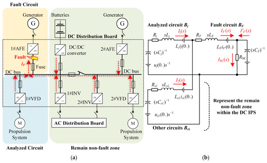
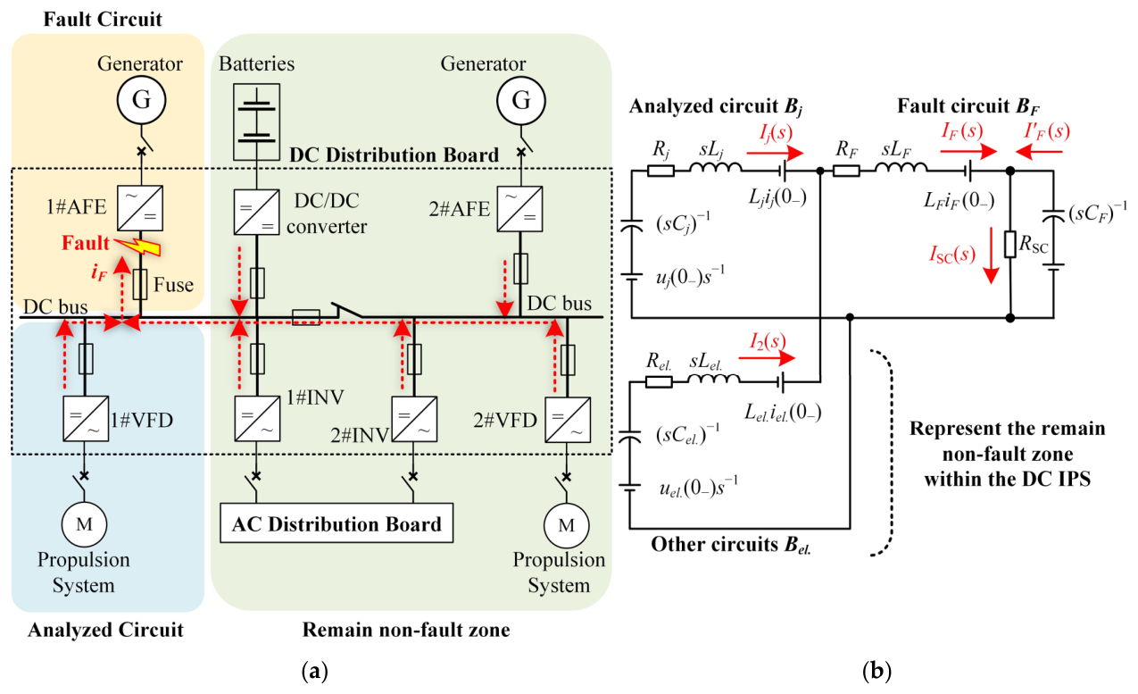
The typical structure of a DC integrated power system (DC IPS) for a small hybrid vessel is illustrated in Figure 1a. The vessel is a passenger ship (FANNENG Co., Ltd., Xiamen, China) designed for Guilin, China. The generators supply power to the DC bus through active front ends (AFEs), while the battery delivers power via DC/DC converters. Variable frequency drives (VFDs) are used to supply power to the propulsion motors, and inverters (INVs) feed the onboard AC distribution system. Each power electronic converter is connected to the DC bus through a fuse. The port and starboard DC buses are interconnected via a fuse and a disconnect switch. The DC distribution board is responsible for power distribution and short-circuit fault protection.
Figure 1.
The typical structure of the DC IPS and its simplified analysis model for a single-point short-circuit fault. (a) Structure of a DC IPS. 1# and 2# are the indices. (b) Analysis model for a single-point short-circuit fault.
Short-circuit faults within the DC IPS distribution board are cleared by fuses. The fault current flowing through the fuse in the faulted circuit is primarily supplied by converters in non-faulted circuits. Due to the rapid transient behavior, the short-circuit current is mainly contributed by the discharge of the input or output capacitors of the converters. The Joule integral generated by this capacitor discharge current is the dominant factor triggering fuse operation.
Prior to fuse operation, each converter is equivalently modeled (see Figure 1b) as a capacitor with parasitic resistance, while busbars, cables, and other components are represented by series resistance–inductance elements. The fuse is modeled as a resistor. In this equivalent model, the capacitance, resistance, and inductance of each circuit are denoted as Cind, Rind, and Lind, respectively, where ind represents the circuit index. The short-circuit transition resistance is denoted as RSC. The non-faulted circuit under analysis is denoted as circuit Bj, the remaining non-faulted circuits are collectively represented as circuit Bel., and the faulted circuit is denoted as circuit BF.
According to Kirchhoff’s laws, the relationships among these circuits are
where i is the current in a circuit, I is the Laplace transform of i, u is the voltage of the output or input capacitor of the converters, and s is the complex frequency in the Laplace domain.
Since Equation (1) is difficult to solve analytically, the following assumptions are introduced to simplify the analysis. (a) The discharge duration of C2 is extremely short and has a negligible effect on IF. (b) The short-circuit current is significantly larger than the steady-state operating current, allowing the initial currents in all circuits to be neglected. (c) All capacitors have the same initial voltage, denoted as U0.
Then, Equation (1) can be simplified as
From Equation (2), the currents in each circuit can be obtained as
where
According to Equation (3), in the correlation between the short-circuit fault current IF and the current Ij, α can be eliminated. Therefore, the relationship between IF and Ij can be expressed as
It can be seen that the correlation between the IF and the Ij is mainly determined by the circuits’ parameters and time.
We define the relationship IF(s) = g(s)Ij(s). Because the system parameters of the DC IPS are constant, g(s) is a function of s alone. The inverse Laplace transform of Equation (5) is then expressed as
where denotes the inverse Laplace transform.
A further analysis is performed to examine the relationship among the Joule integrals of different DC IPS circuits. Based on the definition of the Joule integral, the equivalent short-circuit current, which is the root-mean-square (RMS) of the current in a circuit, is defined as
Thus, an important inference can be drawn: the mapping relationship from the current in a non-fault circuit to in the fault circuit is governed by the resistance, inductance, and capacitance parameters of the non-fault circuits, and varies with the fault duration.
Consequently, Equation (7) can be expressed as
where GRFT(j→F) represents the mapping from the equivalent short-circuit current of a single non-fault circuit Bj to that of the fault circuit BF.
However, since the circuit Bel. is an equivalent model synthesized from multiple non-fault circuits, its resistance, inductance, and capacitance parameters cannot be directly derived from the physical configuration of the DC IPS. Therefore, an artificial neural network (ANN) is introduced to establish the mapping relationship GRFT(j→F).
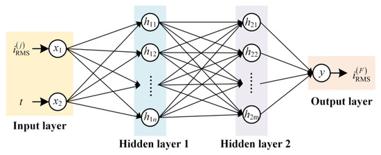
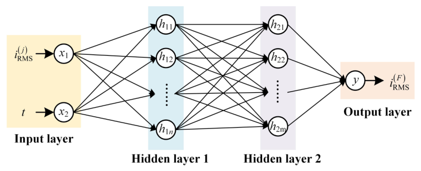
The ANN used to establish GRFT(j→F) is a fully connected neural network with two hidden layers, as shown in Figure 2. The network takes the RMS short-circuit current of circuit Bj and its corresponding time series t as inputs, and outputs the RMS current of the faulted circuit BF. Based on the analysis presented in this paper, a two-hidden-layer architecture is selected, with 9 and 4 neurons in the first and second hidden layers, respectively. Considering that the number of DC IPS branches increases, the size of the training dataset and the number of neural networks need to grow significantly. To reduce the computational burden and shorten the fuse-setting time, the Tansig function is selected as the activation function and Bayesian regularization is applied as the training method in this study. The Tansig function is as shown in Equation (9). The network performance is evaluated using the covariance between the predicted and actual values. By training the ANN with data generated from the equivalent short-circuit fault model of the DC IPS, the mapping relationship GRFT(j→F) can be obtained.
Figure 2.
Structure of the ANN for establishing the mapping relationship GRFT(j→F) between non-faulted and faulted circuits.
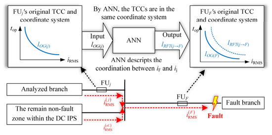
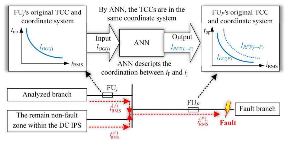
The time–current characteristic (TCC) curve of a fuse is defined by the operating time top and the corresponding equivalent short-circuit current iRMS, where top decreases as iRMS increases. Here, iRMS denotes the root-mean-square current flowing through the fuse. In DC IPS, due to the discrepancy between faulted and non-faulted circuit currents, the TCC curves of fuses in different circuits cannot be directly compared to assess coordination. To address this issue, an ANN is constructed using short-circuit current data of the DC IPS to establish the mapping relationship GRFT(j→F) between circuits under fault conditions. Based on this mapping, the inherent TCC of a fuse in one circuit can be transformed into the time–current coordinate system of another circuit, thereby, as shown in Figure 3, enabling the systematic development of a fuse coordination method.
Figure 3.
ANN-based TCC curves mapping.
2.2. Neurons and Hidden Layers
The number of hidden layers and the number of neurons in each layer of the ANN have a direct impact on the mapping accuracy of GRFT(j→F). Accordingly, an orthogonal experimental design is employed to determine the optimal network depth and width.
Based on the simplified short-circuit fault model of the DC IPS shown in Figure 1b, a simulation model is established in MATLAB/Simulink 2022b. According to the parameters of the practical DC IPS, an 11-factor, 3-level orthogonal table is set, as shown in Table 1. The L27(310) orthogonal array is used to design the experiments, resulting in a total of 27 test cases. For each test case, the ANN is trained and validated using the short-circuit current waveforms obtained from the simulation model with the corresponding test case’s configuration. The ANN training is conducted on the MATLAB platform using an AMD EPYC 7R32 CPU.
Table 1.
Orthogonal table.
The trained ANN is then used to estimate the which is in or not in the training data. The suitability of each network configuration (i.e., number of layers and neurons) is evaluated based on the maximum absolute error between the estimated and actual . This error represents the worst-case prediction error across the orthogonal experiments.
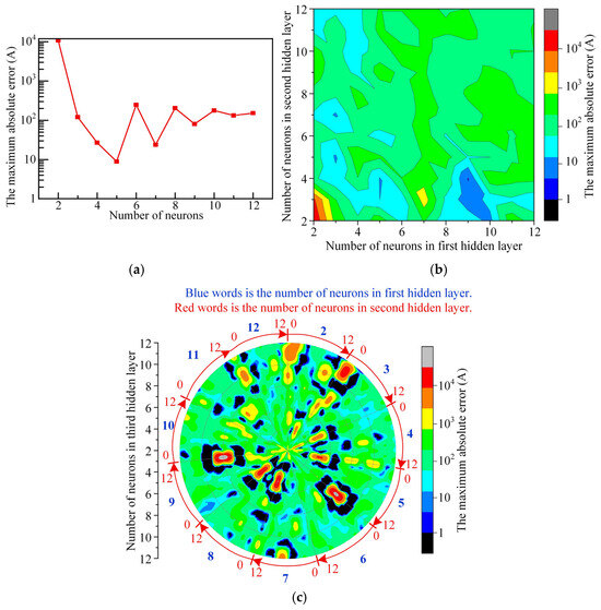
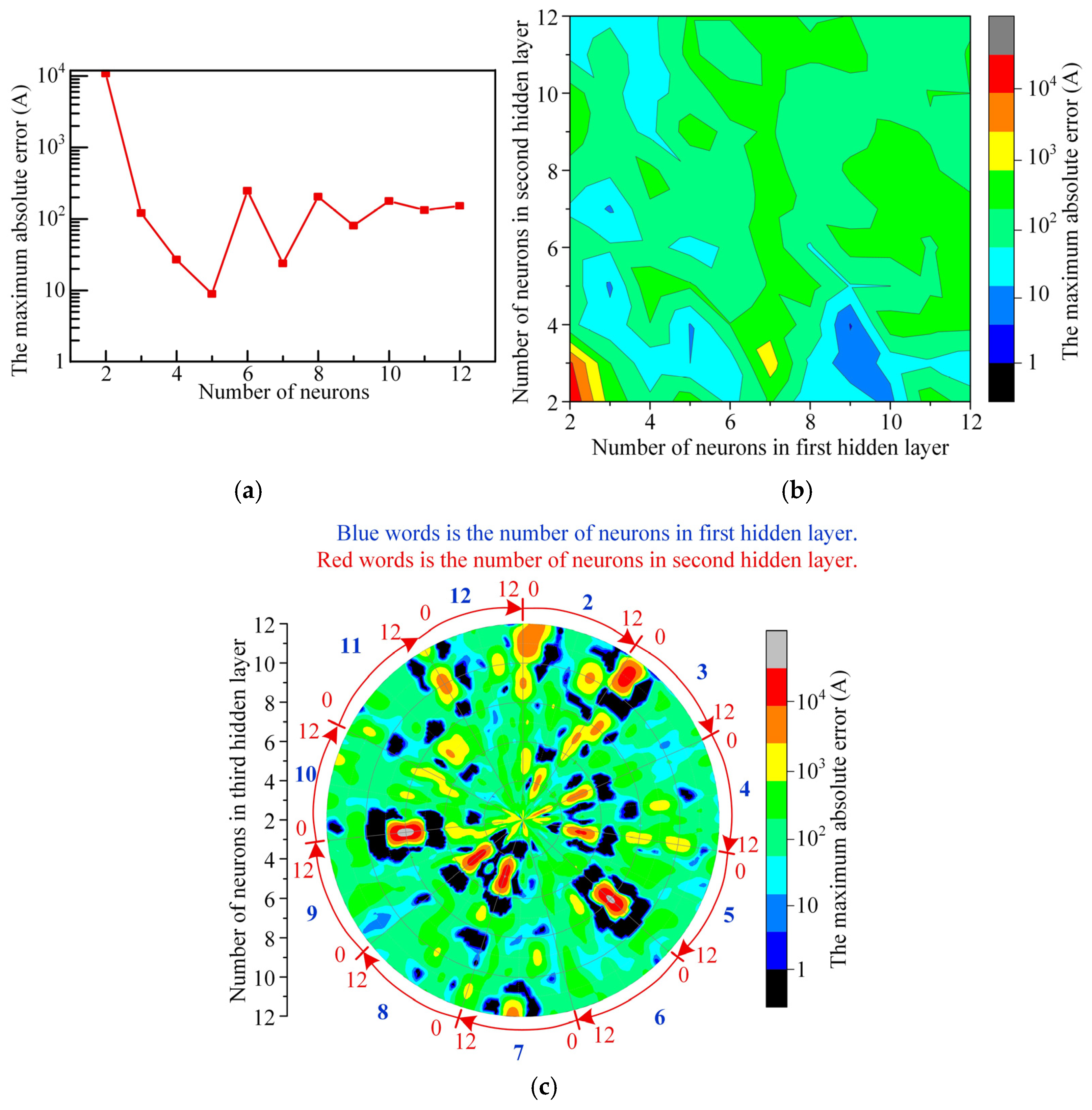
The maximum absolute error for different numbers of neurons and hidden layers is presented in Figure 4. When the neural network contains a single hidden layer, the maximum absolute error decreases below approximately 200 A as the number of neurons increases, reaching a minimum of 10 A. With two hidden layers, the error remains relatively small when the first and second hidden layers contain 8–10 and 2–5 neurons, respectively. For three hidden layers, the region with minimal maximum error expands slightly, but the overall improvement is insignificant.
Figure 4.
The maximum absolute error for different numbers of neurons and hidden layers. (a) Single hidden layer. (b) Two hidden layers. (c) Three hidden layers.
Table 2 summarizes the analysis results for neural networks with different numbers of hidden layers and neurons. In terms of training data fitting accuracy, the minimum value of the maximum absolute error is 8.83 A for the single-hidden-layer network (with 5 neurons), 3.32 A for the two-hidden-layer network (with 9 and 4 neurons in the first and second hidden layers, respectively), and 3.15 A for the three-hidden-layer network (with 9, 7, and 4 neurons, respectively). In terms of training time, the single-epoch training time is 1.64 s for the single-hidden-layer network, 6.29 s for the two-hidden-layer network, and 12.94 s for the three-hidden-layer network.
Table 2.
Analysis of hidden layer configurations and neuron numbers in the ANN.
Compared with the single-hidden-layer network, the two-hidden-layer network improves the fitting accuracy by approximately 60%, while it is only about 5% lower than that of the three-hidden-layer network. Meanwhile, its training time is reduced by approximately 51% compared with the three-hidden-layer network. Considering both fitting accuracy and computational efficiency, the neural network with two hidden layers is selected in this study, with 9 neurons in the first hidden layer and 4 neurons in the second.
2.3. Generalization Capability Analysis
Further analysis is conducted to evaluate the generalization capability of the ANN. This capability was assessed by examining the mapping accuracy under conditions with larger short-circuit transition resistances and extended fault durations. The data of these conditions is untrained for the ANN.
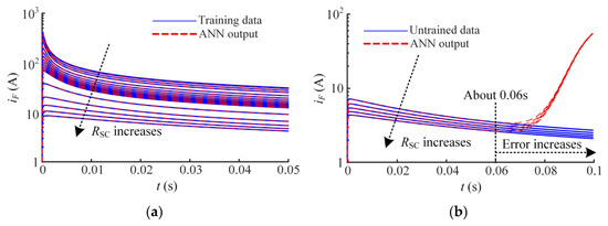
Figure 5a illustrates the mapping performance of the ANN under training data conditions, where the short-circuit transition resistance ranges from 1 μΩ to 100 mΩ, and the fault duration is within 0.05 s. The ANN maps the RMS short-circuit current of circuit Bj to that of circuit BF, and as shown in the figure, it demonstrates excellent mapping accuracy.
Figure 5.
ANN’s performance and generalization. (a) Accuracy of ANN with training data. (b) Generalization of ANN with untrained data.
Figure 5b presents the mapping results under extrapolated conditions, where the short-circuit transition resistance varies from 120 mΩ to 200 mΩ, and the fault duration extends to 0.1 s. It can be observed that the mapping accuracy remains high before approximately 0.05 s, indicating that the ANN maintains good generalization capability when dealing with short-circuit conditions involving higher transition resistances. However, after about 0.06 s, the mapping error increases rapidly, suggesting that the ANN’s generalization deteriorates for longer fault durations.
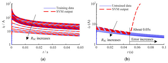
The performance and generalization of ANN and Support Vector Machines (SVM) are further compared. An SVM model is trained and validated on the same training platform as the ANN. The results are presented in Table 3 and Figure 6. As shown in Table 3, the ANN exhibits both faster training speed and lower prediction error compared with the SVM. As illustrated in Figure 5 and Figure 6, the SVM demonstrates inferior generalization performance under higher transition resistances, while showing no significant improvement for longer short-circuit durations compared to the ANN.
Table 3.
Comparison between ANN and SVM.
Figure 6.
SVM’s performance and generalization. (a) Accuracy of SVM with training data. (b) Generalization of SVM with untrained data.
In addition, ANNs are generally more suitable for handling large-scale datasets than SVMs. During the acquisition of short-circuit current data in DC IPS, due to the low system impedance, the current typically rises to tens of kiloamperes within a few milliseconds. To accurately capture the full evolution of the short-circuit current, the sampling interval is typically in the order of microseconds or even nanoseconds. Consequently, for fault durations on the order of tens of milliseconds—which are already relatively short in the context of protection coordination—the dataset size can reach hundreds of thousands to millions of samples.
In summary, the ANN is adopted in this study to characterize the mapping relationships of short-circuit currents among different circuits in the DC IPS. Due to the limited generalization capability of the ANN for extended fault durations, it is necessary to truncate the TCC curves of fuses according to the short-circuit fault duration during fuse coordination. This prevents deviations in the mapped TCC curves from the actual values, which could otherwise lead to incorrect judgments regarding the satisfaction of selective protection requirements. If a longer time range of the TCC curves is required, the short-circuit fault duration used for generating the ANN training data should be correspondingly extended. In practical fuse coordination, the short-circuit fault duration can be determined based on the maximum allowable fuse operation time between fault occurrence and fuse operation.
3. ANN-Based Fuse Coordination
3.1. Requirements for Fuse Coordination
Section 3.2.2 of the “Inspection Guidelines for Shipboard DC Integrated Power Systems” [25] and Section 2.5.4 of Part Four of the “Rules for Classification of Seagoing Steel Ships” [26] issued by the China Classification Society clearly specify the requirements for fuse-based protection schemes and the selection of fuses in DC IPS.
- (1)
- For short-circuit protection schemes
To ensure effective short-circuit protection, only the fuse closest to the fault location should disconnect the faulty circuit, while other fuses must withstand the short-circuit current without tripping. Given the high amplitude and rapid rise rate of short-circuit currents in DC systems, fault clearance must be achieved as quickly as possible. Consequently, short-circuit protection in DC IPS must simultaneously satisfy the dual requirements of selectivity and rapidity.
- (2)
- For the selection of fuses
Requirement I: The fuse rated current Ie must be greater than the maximum normal continuous operating current IS of the associated distribution line, with an appropriate margin. This requirement can be expressed as
where λ1 is a coordination margin that accounts for ambient temperature, cooling conditions, and the safety margin. λ1 must be greater than 1.
Requirement II: During the interval between short-circuit fault initiation and clearance, the Joule integral I2t of each fuse in the non-faulted area must remain below half of its inherent pre-arcing Joule integral I2tpre-arcing. This requirement can be expressed as
where λ2 is another coordination margin that accounts for the DC IPS recovery process following short-circuit protection, as well as the thermal stress experienced by fuses in non-faulted zones. Typically, λ2 should be no less than 2.
Fuses interrupt fault currents based on the thermal melting principle, thereby exhibiting inverse TCCs. Under different fault transition resistances RF, the fuse’s minimum melting time top and RMS short-circuit current change. The curve formed by points (top, ) when the fuse melt represents the fuse’s TCC curve. Let the inherent TCC curve of the fuse in circuit Bj be denoted as l(j). Since each fuse operates based on its own current, analyzing protection coordination across different circuits requires mapping all fuses’ TCC curves onto a unified time–current coordinate plane.
In the proposed coordination method, all fuses’ TCC curves are mapped onto the time–current coordinate plane of the faulted circuit. Based on Equation (8), the equivalent TCC curve leq(j→F), representing the mapping of the original curve l(j) from the circuit Bj onto the faulted circuit BF’s coordinate system, is defined as
Then, Requirement II can be expressed as:
Equation (13) indicates that when the equivalent TCC curve leq(j→F) of the non-faulted circuit Bj lies above l(F) by , the fuse in circuit BF will operate first upon the occurrence of a short-circuit fault in that circuit.
In summary, when the fuse selection satisfies the criteria specified in Equations (10) and (13), effective short-circuit fault protection of the DC IPS is ensured.
3.2. Fuse Coordination Method
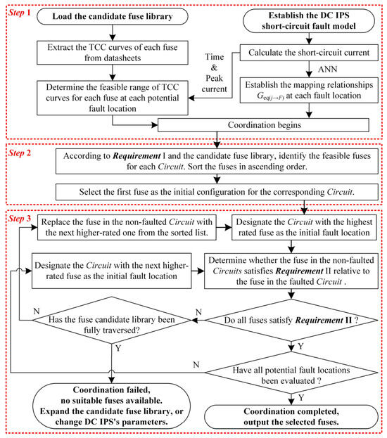
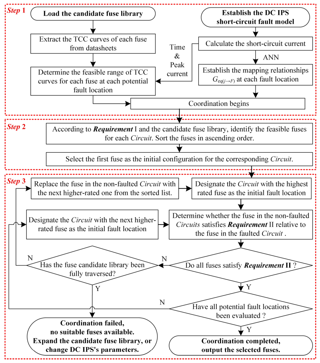
Based on the above analysis, the coordination method shown in Figure 7 is established. The coordination steps are as follows.
Figure 7.
Flowchart of the proposed fuse coordination method.
Step 1: Select the fuse brands and specifications to construct a candidate fuse library for the DC IPS, and extract their corresponding TCC curves from datasheets. Establish a short-circuit fault model of the DC IPS and compute the short-circuit current at each potential fault location. Using these results, derive the current mapping relationships Geq(j→F) between the non-faulted and faulted circuit. Based on the peak short-circuit current of each circuit and the simulation time, determine the feasible range of TCC curves for each fuse at each potential fault location. These TCC curves serve as the criterion for evaluating whether a candidate fuse will operate under given fault conditions. Fuse coordination is then performed accordingly.
Step 2: According to Requirement I and the candidate fuse library, identify the feasible fuses for each circuit. Group these fuses into sets corresponding to each circuit. Within each set, sort the fuses in ascending order based on their TCCs. Select the first fuse in each set as the initial configuration for the corresponding circuit.
Step 3: Sort the initially selected fuses and designate the circuit with the highest rated fuse as the initial fault location. Then, evaluate whether the fuses in the non-faulted circuits, together with the fuse in the faulted circuit, satisfy Requirement II.
If Requirement II is not satisfied, update the fuse in the first non-faulted branch that fails to meet the criterion to the next specification in its candidate set, and reevaluate the satisfaction of Requirement II. If a circuit exhausts all fuse options in its candidate set without achieving compliance with Requirement II, this indicates that the current candidate fuse library is insufficient, and the candidate fuse library must be expanded; the DS IPS’s parameters should change, such as the capacitors [15].
If Requirement II is satisfied, proceed by identifying the circuit with the second-highest-rated fuse as the next fault location. Reassess whether the coordination between this faulted circuit and the remaining non-faulted circuits still meets Requirement II. Once all potential fault locations in the DC IPS have been evaluated and successfully satisfy Requirement II, the fuse coordination process is considered complete. The resulting fuse selection ensures both selectivity and speed in short-circuit protection for the DC IPS.
4. Case Studied and Results
Based on a hybrid vessel DC IPS design developed by our industrial partner, the proposed fuse coordination method is verified. The vessel is a passenger vessel. The structure of the DC IPS for this vessel is shown in Figure 1a. The power sources consist of a 196 kWh battery, a 75 kW generator, and a 200 kW generator. The load side includes two 75 kW propulsion systems and two 48 kW inverters.
4.1. DC IPS Short-Circuit Fault Model
4.1.1. Short-Circuit Fault Model
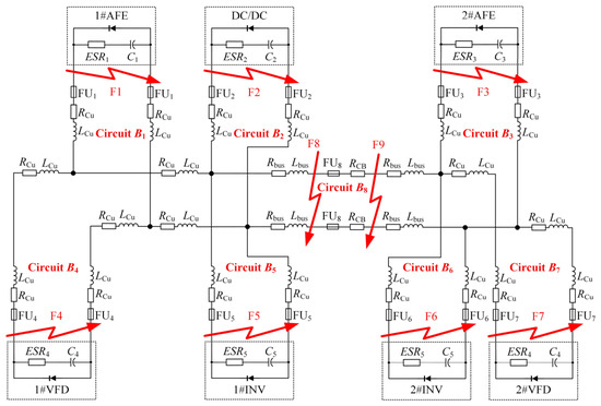
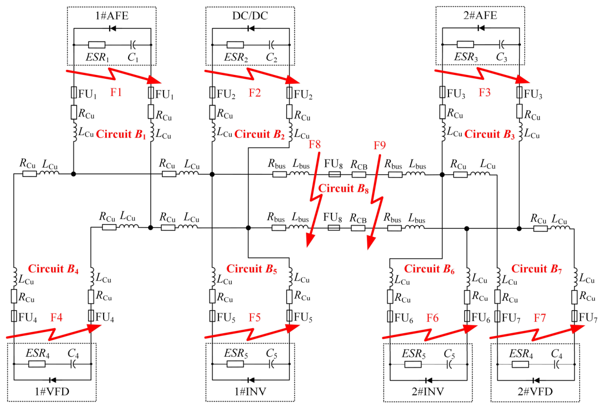
Based on the structure of the DC IPS (see Figure 1a), the short-circuit fault model of the DC IPS, as shown in Figure 8, is established in MATLAB/Simulink. The model parameter list is in Appendix A Table A1. This simulation model is used to generate short-circuit current data, train the ANN, derive the mapping relationship between faulted and non-faulted circuits, and verify fuse coordination. In the model, each converter is represented by a capacitor Cj, a capacitor series parasitic resistance ESRj, and an antiparallel diode. Cables and busbars are modeled by a resistor Rj and an inductor Lj. The fuse model FUj is described below. Here, j is a positive integer representing the index of the circuits.
Figure 8.
Equivalent model for the single-point short-circuit fault in the DC IPS case. F1 to F9 are fault points. #1 to #7 are the indices.
4.1.2. Fuse Model
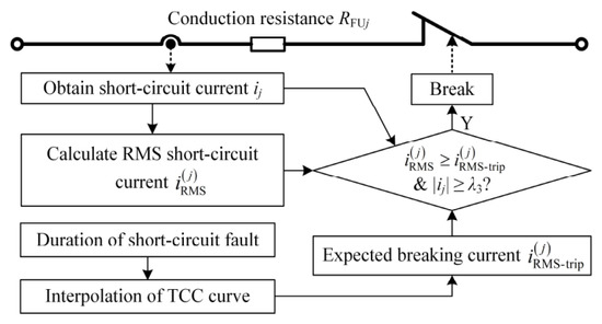
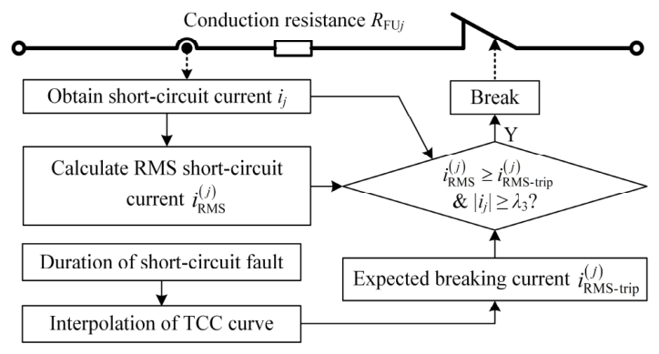
The equivalent model of the fuse is illustrated in Figure 9. In the conducting state, the fuse is represented by a resistance RFUj. After a short-circuit fault occurs, the fuse determines whether to interrupt the current based on its TCC curve. The decision process is as follows: once a fault is detected, the short-circuit current is continuously monitored, and the RMS short-circuit current is calculated according to Equation (7). Simultaneously, based on the fault duration and the TCC curve, the expected RMS short-circuit current that triggers fuse breaking is obtained through interpolation. When the absolute short-circuit current ij is larger than a very small threshold λ3, which is 1 A in this paper, the fuse blows, and the normally closed switch in Figure 9 opens to interrupt the current. The candidate fuse models used in this study and their TCC curves are acquired from datasheets [27]. The conduction resistance RFUj of the fuse FUj is
where Ie is the rated current and Pe is the rated power loss.
Figure 9.
Fuse model.
4.2. Coordination Results
Based on the process shown in Figure 7, the fuse coordination for the DC IPS case is performed. In the coordination, λ1 is 1.1 and λ2 is 2. According to the fuse candidate library shown in Appendix A Table A2, the fuse coordination results are shown in Table 4.
Table 4.
Fuse coordination results.
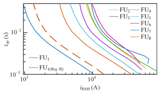
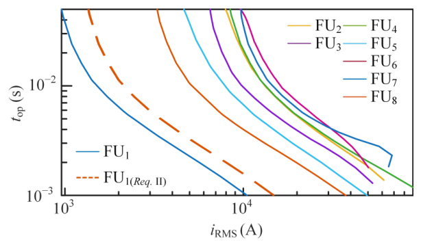
Under the fuse configuration shown in Table 4, the relationships among the TCC curves of each fuse at different short-circuit fault locations are analyzed. In the results (see Figure 10), the solid lines represent the TCCs of each fuse mapped onto the time–current coordinate plane of the faulted circuit, while the dashed lines indicate the margin TCC curve of the fuse in the faulted circuit as specified by Requirement II. The inherent TCC curve of the fuse in the faulted circuit lies entirely below the equivalent TCC curves of fuses from non-faulted circuits mapped onto the same plane. Moreover, equivalent TCC curves of fuses from non-faulted circuits are all positioned above the margin TCC curve, thereby satisfying Requirement II. This ensures that the fuse in the faulted circuit operates before those in other branches, achieving full selectivity in short-circuit protection.
Figure 10.
Illustrative fuse coordination analysis at fault point F1.
4.3. Short-Circuit Fault Protection Verification
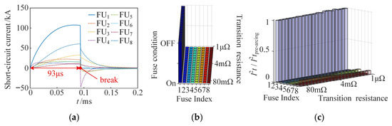
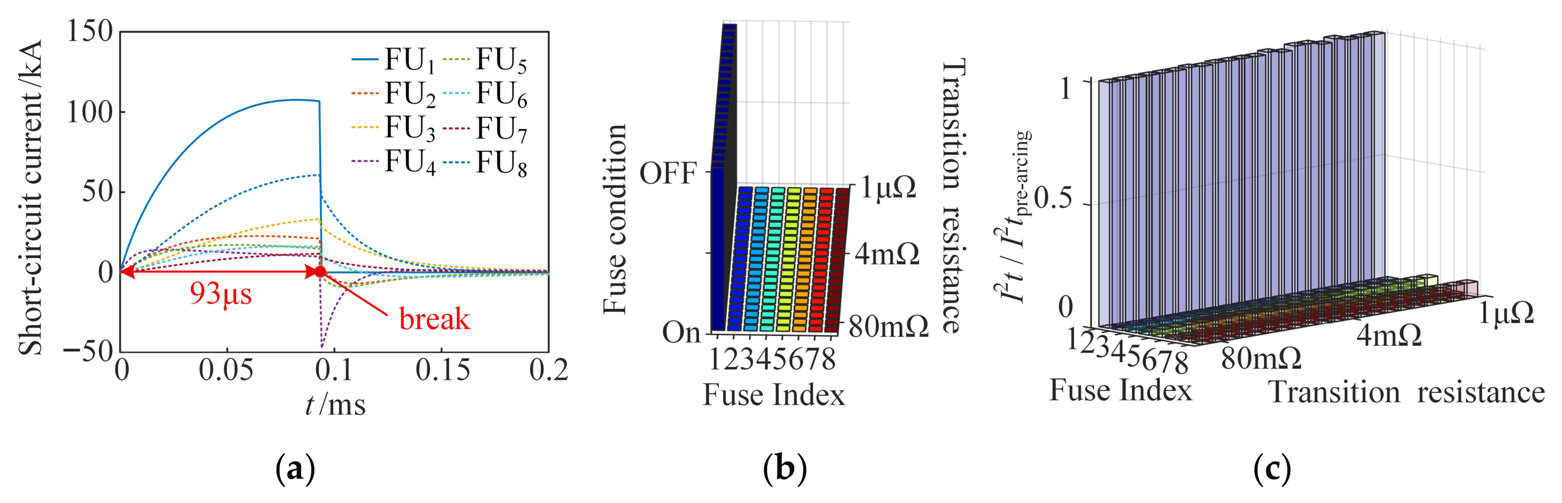
Figure 11a shows the short-circuit current flowing through each fuse when the short-circuit transition resistance is 1 μΩ at fault location F1 (see Figure 8). Among them, FU1 experiences the highest current amplitude. FU1 operates 93 μs after the fault occurs, isolating the faulted zone, while the other fuses remain closed—thus meeting the selectivity requirement for short-circuit protection. The operating status of each fuse under varying short-circuit transition resistances is shown in Figure 11b, all of which satisfy the selectivity requirements of the DC IPS. Further analysis of the Joule integral of the fuses at the moment FU1 operates is provided in Figure 11c, showing that all fuses meet Requirement II. In combination with Figure 11 and other fault locations, it can be concluded that the selected fuses listed in Table 4 meet the short-circuit protection coordination requirements under various fault locations and short-circuit transition resistances.
Figure 11.
Illustrative protection coordination verification at fault point F1. (a) Short-circuit currents. (b) The condition of each fuse. (c) The rate of Joule integral.
4.4. Comparison
Two fuse coordination methods established based on [28,29] are compared in this study. Reference [28] determines the fuse operation time based on the intersection between the Joule integral and the RMS short-circuit current curve, and subsequently evaluates coordination according to the resulting fuse operation times. Reference [29] indicates that TCC curves reflect the operating characteristics of protective devices under different system conditions and can be directly used for selective coordination.
Method 1 is based on [28]. In this method, first, the pre-arcing Joule integral is obtained from the fuse datasheet and treated as a constant. Then, a short-circuit transition resistance of 1 μΩ is assumed to calculate the short-circuit current and its corresponding Joule integral. For each circuit, the fuse is considered to operate when the Joule integral of the short-circuit current reaches the pre-arcing value. By comparing the operating times of fuses under different fault locations, the protection coordination is evaluated. A fuse setting that satisfies selective protection under the 1 μΩ condition is selected, and its effectiveness is subsequently verified under varying short-circuit transition resistances.
Method 2 is based on [29]. This method is generally similar to Method 1, with the key difference being that the fuse operation time is determined from the intersection between the fuse TCC curve and the RMS short-circuit current curve. Consequently, the corresponding Joule integral is no longer constant but varies with the system conditions of the DC IPS. Finally, the effectiveness of the resulting fuse settings is also verified under different short-circuit transition resistances.
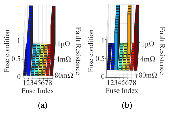
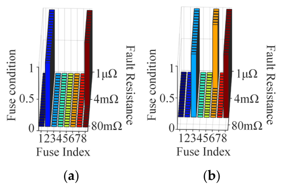
For both methods, λ1 is 1.1 and λ2 is 2. The coordination results are shown in Table 5, and the verification results are illustrated in Figure 12. As shown in Figure 12, both traditional methods result in the misoperation of fuses in non-faulted branches. This occurs because Method 1 neglects the fuse’s intrinsic TCC, while Method 2 overlooks the effect of varying transition resistance on the short-circuit behavior of the DC IPS. Consequently, these methods fail to ensure selective protection under conditions with low λ1 and λ2, which are essential for achieving rapid fault clearance in DC IPS short-circuit scenarios.
Table 5.
Coordination results with Method 1 and 2.
Figure 12.
Protection coordination verification. (a) With Method 1, F2 does not meet the protection requirements. (b) With Method 2, F3 does not meet the protection requirements.
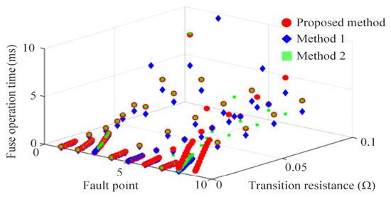
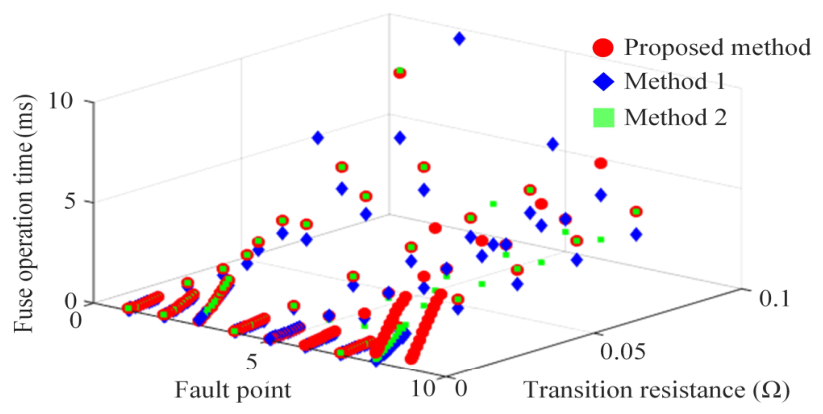
To further evaluate the superiority of the proposed fuse coordination scheme in terms of response speed, a comparative analysis of the fuse operation time in faulted circuits is conducted. In this analysis, the limitations of Methods 1 and 2 in protection selectivity are disregarded.
Figure 13 presents the comparison results of fuse operation time between the proposed scheme and Methods 1 and 2. The results show the operation time of the fuses when short-circuit faults occur in their corresponding circuits. Under fault conditions F1 to F7, the fuses configured using the proposed scheme exhibit slightly shorter or comparable operation times relative to those obtained with Method 1 or 2. Under fault points F8 and F9, the conventional approaches fail to satisfy the protection selectivity requirements, whereas the proposed method maintains the fuse operation times within 6 ms.
Figure 13.
Comparison of fuse operation time.
These results demonstrate that the fuse coordination method proposed in this paper achieves faster protection response while simultaneously ensuring protection selectivity, thereby offering a more effective and reliable short-circuit protection scheme for DC IPS.
4.5. Additional DC IPS Case
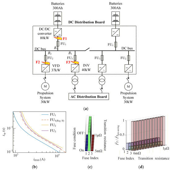
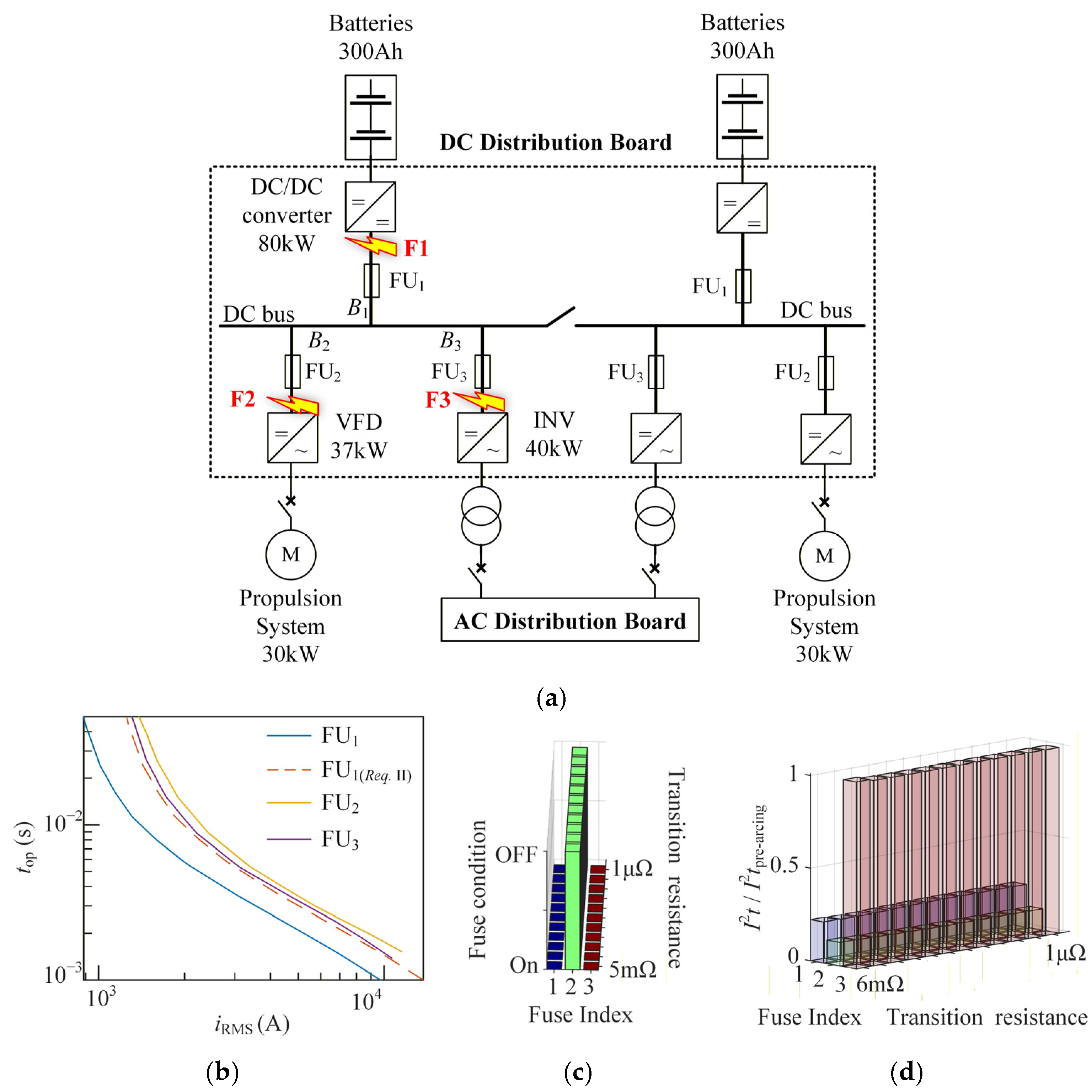
To further demonstrate the effectiveness of the proposed fuse coordination method, an additional DC IPS case study is incorporated. The proposed method is validated based on a pure electric sightseeing vessel currently under development by our industrial partner (FANNENG Co., Ltd., Xiamen, China). The DC IPS configuration of the vessel is shown in Figure 14a, and the parameters of the short-circuit fault equivalent model are listed in Appendix A Table A3. The power sources consist of two 300 Ah battery systems, while the loads include two 30 kW propulsion systems and two 40 kW inverters. Each converter is connected to the DC bus through fuses. Under normal operating conditions, the port and starboard DC busbars operate independently to supply power to their respective loads, without interconnection. Due to the symmetrical arrangement of the port and starboard systems, the fuse selection is also symmetric. Therefore, the fuse coordination can be performed based on either the port-side or starboard-side configuration.
Figure 14.
Structure of the additional DC IPS case and verification results of fuse coordination. (a) Configuration of the DC IPS case. (b) Comparison of the fuses’ TCC curves at the fault point F1. (c) Fuse operating states under short-circuit fault conditions at the fault point F2 (OFF indicates fuse operation, while ON indicates that the fuse remains conducting). (d) Joule integral responses of fuses under short-circuit fault conditions at the fault point F3.
The resulting fuse coordination result is presented in Appendix A Table A4, and the protection verification results are shown in Figure 14b,c. It can be observed that, under various single-point short-circuit fault conditions, only the fuse closest to the fault location operates, while the remaining fuses continue to conduct. Moreover, the Joule integral values of the fuses in non-faulted circuits remain below half of their respective pre-arcing Joule integral limits. These results confirm that the proposed fuse coordination method satisfies the selective protection requirements of the DC IPS.
5. Conclusions
This paper proposes a fuse coordination method for DC IPS that satisfies both selectivity and rapidity requirements for short-circuit fault protection. The method employs an ANN to model the mapping relationship between the short-circuit currents of faulted and non-faulted circuits. Once this mapping relationship is established, the TCC curves of fuses in different circuits can be transformed into a unified time–current coordinate system, enabling engineers to directly evaluate protection coordination based on the relative positions of TCC curves.
- (1)
- In DC IPS, the relationship between the short-circuit currents of faulted and non-faulted circuits is primarily determined by the converter capacitance, the resistance and inductance of the circuits, and the short-circuit duration. This relationship is largely independent of the short-circuit transition resistance.
- (2)
- A two-hidden-layer artificial neural network can effectively model the current relationship between faulted and non-faulted circuits. While the network demonstrates good generalization under higher short-circuit transition resistances, it fails to accurately capture the current relationship for longer fault durations.
- (3)
- By mapping the TCC curves of protective switching devices onto a unified time–current coordinate plane, the selectivity of short-circuit fault protection can be intuitively evaluated based on the relative positions of the curves. Prioritizing the selection of protective devices with lower TCC curves can ensure both selectivity and rapidity in DC IPS short-circuit protection.
The DC IPS short-circuit protection coordination method proposed in this study has been validated on a hybrid passenger vessel and a pure electric sightseeing vessel. By considering both the TCCs of fuses and the influence of short-circuit transition resistance on system fault behavior, this method addresses key limitations of traditional approaches. In the future, as solid-state circuit breakers and other intelligent electronic devices become more compact and cost-effective, the proposed method can also be extended to the self-coordination of TCCs for such devices. The proposed method demonstrates strong potential for wider application in short-circuit protection analysis and fuse coordination in other multi-source DC power systems.
Author Contributions
Conceptualization, C.Z., X.D., Y.M. and R.Y.; methodology, C.Z., X.D., W.L. and C.L.; software, C.Z., X.D., Y.M., R.Y. and C.L.; validation, C.Z., X.D., Y.W. and C.L.; formal analysis, C.Z., Y.W. and Y.C.; investigation, C.Z., X.D., W.L. and W.Y.; resources, C.Z., W.L. and Y.C.; data curation, C.Z., X.D. and Y.M.; writing—original draft preparation, C.Z., X.D., Y.M. and R.Y.; writing—review and editing, C.Z., W.L., C.L.,Y.C., Y.W. and W.Y.; visualization, C.Z., X.D., Y.M. and R.Y.; supervision, C.Z., W.L., C.L., Y.C., Y.W. and W.Y.; project administration, C.Z., W.L. and C.L.; funding acquisition, C.Z., Y.C. and C.L. All authors have read and agreed to the published version of the manuscript.
Funding
This work was supported by Natural Science Foundation of Fujian Province (2025J01868, 2024J01710, 2022J01813), Middle-aged and Young Teacher Education Research Project of Education Bureau of Fujian Province (JZ240032), and Key Laboratory Open Topics of New Energy Generation and Power Conversion (KFKL202505).
Data Availability Statement
Data are contained within the article.
Conflicts of Interest
The authors declare no conflicts of interest.
Appendix A
Table A1.
Key parameters of DC IPS short-circuit fault model for the hybrid passenger ship.
Table A2.
Fuse candidate library.
Table A3.
Key parameters of DC IPS short-circuit fault model for pure electric sightseeing ship.
Table A4.
Fuse coordination result.
References
- Ma, W.; Xiao, F.; Ma, F. Research Progress and Application Suggestions of Integrated Power System for Ships. Proc. CSEE 2024, 44, 6761–6775. [Google Scholar]
- Yin, H.; Lan, H.; Hong, Y.-Y.; Wang, Z.; Cheng, P.; Li, D.; Guo, D. A Comprehensive Review of Shipboard Power Systems with New Energy Sources. Energies 2023, 16, 2307. [Google Scholar] [CrossRef] [Scilit]
- Jithin, K.; Haridev, P.P.; Mayadevi, N.; Harikumar, R.P.; Mini, V.P. A Review on Challenges in DC Microgrid Planning and Implementation. J. Mod. Power Syst. Clean Energy 2023, 11, 1375–1395. [Google Scholar] [CrossRef] [Scilit]
- Yang, Y.; Tai, N.; Huang, W.; Yu, M.; Liu, Y. Medium-voltage DC Integrated Power System for Ships (Part II): Fault Protection Management Technology. Trans. China Electrotech. Soc. 2024, 39, 7341–7364. [Google Scholar]
- Sun, Y.; Fan, Y.; Hou, J.; Song, G. A Unit Protection Scheme Based on the Transient Current Coordinate Mapping Interval. Prot. Control Mod. Power Syst. 2025, 10, 103–120. [Google Scholar] [CrossRef] [Scilit]
- Godoy, J.V.; Negri, S.; Oliva, F.; Antoniazzi, A.; Faranda, R.S. Innovative Fault Current Evaluation Method for Active DC Grids. Electronics 2024, 13, 847. [Google Scholar] [CrossRef] [Scilit]
- Mahdi, H.; Hoff, B.; Ostrem, T. A Review of Power Converters for Ships Electrification. IEEE Trans. Power Electron. 2023, 38, 4680–4697. [Google Scholar] [CrossRef] [Scilit]
- Singh, P.; Kumar, U.; Choudhary, N.K.; Singh, N. Advancements in Protection Coordination of Microgrids: A Comprehensive Review of Protection Challenges and Mitigation Schemes for Grid Stability. Prot. Control Mod. Power Syst. 2024, 9, 156–183. [Google Scholar] [CrossRef] [Scilit]
- Mayer, C.; Baumann, M.; Eisenmann, B.; Herzog, H.-G. A Review of Electronic Fuses: Challenges and Opportunities for Future Vehicular Power Systems. IEEE Trans. Transp. Electrif. 2025, 11, 8548–8560. [Google Scholar] [CrossRef] [Scilit]
- Zhang, C.; Dong, Z.; Lu, F.; Ma, R.; Wang, L.; Zhao, H.; Wang, X.; Wang, X.; Tang, H.; Wang, A. Fuse-Based Field-Dispensable ESD Protection for Ultra-High-Speed ICs. IEEE Electron Device Lett. 2014, 35, 381–383. [Google Scholar] [CrossRef] [Scilit]
- Yousaf, M.; Jalilian, A.; Muttaqi, K.M.; Sutanto, D. An Adaptive Overcurrent Protection Scheme for Dual-Setting Directional Recloser and Fuse Coordination in Unbalanced Distribution Networks with Distributed Generation. IEEE Trans. Ind. Appl. 2022, 58, 1831–1842. [Google Scholar] [CrossRef] [Scilit]
- Bui, D.M.; Chen, S.-L.; Wu, C.-H.; Lien, K.Y.; Huang, C.H.; Jen, K.K. Review on protection coordination strategies and development of an effective protection coordination system for DC microgrid. In Proceedings of the 2014 IEEE PES Asia-Pacific Power and Energy Engineering Conference (APPEEC), Hong Kong, China, 7–10 December 2014; IEEE: Piscataway, NJ, USA, 2014; pp. 1–10. [Google Scholar]
- Choi, S.-M.; Kim, J.-M.; You, H.-S.; Lee, N.-K.; Son, M.-S.; Rho, D.-S. A Study on Protection Coordination Method in 5 kV MVDC Off-Grid MG System. J. Electr. Eng. Technol. 2024, 19, 4737–4748. [Google Scholar] [CrossRef] [Scilit]
- Fu, R.; Montross, K.C. A New Method of Coordinating ZCBs and Fuses for a Reliable Short-Circuit Protection in DC Power Networks. IEEE Access 2022, 10, 63270–63279. [Google Scholar] [CrossRef] [Scilit]
- Ravyts, S.; Broeck, G.V.D.; Hallemans, L.; Vecchia, M.D.; Driesen, J. Fuse-Based Short-Circuit Protection of Converter Controlled Low-Voltage DC Grids. IEEE Trans. Power Electron. 2020, 35, 11694–11706. [Google Scholar] [CrossRef] [Scilit]
- Pindado, S.; Alcala-Gonzalez, D.; Alfonso-Corcuera, D.; del Toro, E.M.G.; Más-López, M.I. Improving the Power Supply Performance in Rural Smart Grids with Photovoltaic DG by Optimizing Fuse Selection. Agronomy 2021, 11, 622. [Google Scholar] [CrossRef] [Scilit]
- Chen, L.; Yi, W.; Deng, P.; Ma, S.; Kuang, D.; Cai, H. The Pole-to-Ground Fault Current Calculation Method and Impact Factor Investigation for Monopole DC Grids. Electronics 2025, 14, 1067. [Google Scholar] [CrossRef] [Scilit]
- Bisheh, H.; Fani, B.; Shahgholian, G.; Sadeghkhani, I. Fuse saving coordination scheme for active distribution systems: State-of-the-art and a novel quasi-voltage current based scheme. IET Gener. Transm. Distrib. 2024, 18, 729–755. [Google Scholar] [CrossRef] [Scilit]
- Bisheh, H.; Fani, B.; Shahgholian, G.; Sadeghkhani, I.; Guerrero, J.M. An adaptive fuse-saving protection scheme for active distribution networks. Int. J. Electr. Power Energy Syst. 2023, 144, 108625. [Google Scholar] [CrossRef] [Scilit]
- Barranco-Carlos, A.; Orozco-Henao, C.; Marín-Quintero, J.; Mora-Flórez, J.; Herrera-Orozco, A. Adaptive Protection for Active Distribution Networks: An Approach Based on Fuses and Relays with Multiple Setting Groups. IEEE Access 2023, 11, 31075–31091. [Google Scholar] [CrossRef] [Scilit]
- Murashov, I.; Chishko, S.; Obraztsov, N.; Borovkov, A.; Kamaev, V.; Ponedelchenko, M.; Dolzhenkov, A. Development of a fuse digital model for virtual testing of breaking capacity. Electr. Eng. 2024, 107, 4257–4269. [Google Scholar] [CrossRef] [Scilit]
- Zhao, S.; Blaabjerg, F.; Wang, H. An Overview of Artificial Intelligence Applications for Power Electronics. IEEE Trans. Power Electron. 2021, 36, 4633–4658. [Google Scholar] [CrossRef] [Scilit]
- Esmaeilbeigi, S.; Karegar, H.K.; Akbarisharif, A. An intelligent protection scheme for DC networks using a machine learning-based multi-agent platform. Sci. Rep. 2025, 15, 33124. [Google Scholar] [CrossRef] [Scilit] [PubMed]
- Chen, L. Prediction for Magnitude of Short Circuit Current in Power Distribution System Based on ANN. In Proceedings of the 2011 International Symposium on Computer Science and Society, Kota Kinabalu, Malaysia, 16–17 July 2011; IEEE: Piscataway, NJ, USA, 2011; pp. 130–133. [Google Scholar]
- China Classification Society. Inspection Guidelines for Shipboard DC Integrated Power Systems; China Classification Society: Beijing, China, 2023; p. 14. Available online: https://www.ccs.org.cn/ccswz/specialDetail?id=202303201049576772 (accessed on 10 April 2026).
- China Classification Society. Rules for Classification of Seagoing Steel Ships; China Classification Society: Beijing, China, 2022; Volume 4, p. 23. Available online: https://www.ccs.org.cn/ccswz/articleDetail?id=202506120351271512&columnId=201900002000000016 (accessed on 10 April 2026).
- British EV88 Style Stud-Mount Fuses EV88 Series 750Vdc. Available online: https://offer-product.oss-cn-beijing.aliyuncs.com/product/offer/attachment/947663579/file/subPdf_174150_87618_20220111-131802227.pdf (accessed on 10 April 2026).
- Kim, S.; Kim, S.-N.; Dujic, D. Extending Protection Selectivity in DC Shipboard Power Systems by Means of Additional Bus Capacitance. IEEE Trans. Ind. Electron. 2020, 67, 3673–3683. [Google Scholar] [CrossRef] [Scilit]
- Papallo, T.; Valdes, M.E. Traditional Time Current Curves (TCC) are not enough, adding I2T considerations. In Proceedings of the 2011 IEEE Industrial and Commercial Power Systems Technical Conference, Newport Beach, CA, USA, 1–5 May 2011; IEEE: Piscataway, NJ, USA, 2011; pp. 1–12. [Google Scholar]

Disclaimer/Publisher’s Note: The statements, opinions and data contained in all publications are solely those of the individual author(s) and contributor(s) and not of MDPI and/or the editor(s). MDPI and/or the editor(s) disclaim responsibility for any injury to people or property resulting from any ideas, methods, instructions or products referred to in the content. |
© 2026 by the authors. Licensee MDPI, Basel, Switzerland. This article is an open access article distributed under the terms and conditions of the Creative Commons Attribution (CC BY) license.