


Abstract
As the development of the ocean extends to the deep and open seas, the application of multi-hull floating systems is becoming increasingly widespread, covering offshore oil and gas transfer and material replenishment operations. In multi-body floating systems, the hydrodynamic interactions between adjacent floating bodies significantly affect the overall motion response and load distribution. However, there is currently a lack of systematic experimental research on systems involving three or more units under the combined action of wind, waves, and currents. This study presents a 1:50 scale model experiment on a five-body offshore replenishment station, comprising a central transfer platform and four surrounding vessels. Absolute six-degree-of-freedom motions and relative displacements between the transfer platform and neighboring vessels were measured. The results indicate distinct differences among the units. The peripheral vessels have greater horizontal and yaw motions, while the central units are more restricted. The relative motions are substantially increased for beam and oblique wave conditions, implying increased interaction effects in the gaps between neighboring bodies. Moreover, the combined oblique environmental loading and asymmetric mooring stiffness result in increased global drift and yaw motions. These findings provide benchmark data for numerical validation and practical guidance for the design and operation of multi-body floating systems.
1. Introduction
As marine development activities extend to the open and deep seas, offshore operations increasingly involve coordinated multi-body systems. Multi-body floating systems, including transfer platforms, side-by-side unloading configurations, and multi-module floating platforms, are widely applied in engineering practice. Among them, the offshore replenishment system represents a typical multi-body collaborative operation, primarily responsible for providing offshore vessels with fuel, fresh water, and living supplies. Some systems also incorporate high-speed crafts and barges to facilitate rapid transfer, supporting diverse operations such as emergency rescue, island and reef resupply, and urgent material delivery.
In realistic sea conditions, hydrodynamic interactions among adjacent floating bodies can induce significant variations in wave loads, motion responses, and mooring and fender forces as the separation distances decrease. These interactions can significantly affect operational ranges for cargo or personnel transfer and influence both the motion characteristics and load distribution of the entire system.
Current research on hydrodynamic responses of multi-body floating systems can be broadly categorized into three approaches: theoretical analysis, numerical simulation, and experimental investigation.
The initial theoretical research on multi-body interaction in marine environments mainly focused on understanding the basic fluid dynamics around the structure. For example, Ohkusu [1] successfully predicted the hydrodynamic loads between cylinders in the flow field by using the two-dimensional slice theory. Newman [2] further systematized the theory of wave effects on multiple bodies, establishing a frequency-domain framework for diffraction and radiation analysis. Hong et al. [3] adopted the higher order boundary element method (HOBEM) to calculate the hydrodynamic coefficients, wave drift forces and motion responses of the two hulls alongside the mooring and compared the numerical results with the model test results. The research results showed that the results calculated by the higher-order boundary element method were in better agreement with the test results. Feng and Bai [4] detailed the complex dynamics of floating structures under various wave conditions, which helps to optimize design parameters and improve safety and efficiency. More recently, Fan et al. [5] proposed an innovative concept of a five-body antipitching semi-submersible floating wind turbine, showing the potential of multi-body layouts and coupling designs to reduce pitch motion and enhance stability under wave excitation.
Numerical simulations have been increasingly used to investigate complex multi-body configurations. Coupled frequency and time-domain methods enable the simulation of multi-body dynamics under irregular seas with mooring and power-take-off devices. Konispoliatis et al. [6] conducted coupled analyses on a multi-purpose floating platform integrating wind turbines, oscillating water column (OWC) devices, and a mooring system, emphasizing the sensitivity of dynamic responses to sea state and structural arrangement. Jiang et al. [7] numerically investigated viscous hydrodynamic interactions between side-by-side floating bodies using RANS CFD, demonstrating that narrow-gap effects significantly modify added mass, damping coefficients, and wave-induced loads, with interaction forces governed by asymmetric free-surface elevations. Chen et al. [8] developed a numerical model of a floating wind–wave hybrid platform, demonstrating how the arrangement of bodies and wave incidence directions affect motion responses and power performance. Lamei et al. [9] analyzed the dynamic responses of a multi-unit floating offshore wind turbine using frequency-domain formulations, demonstrating that hydrodynamic coupling among adjacent units governs both rigid-body motions and elastic responses under combined wave–current loading. Extending similar numerical approaches to modular renewable platforms, Wu et al. [10] showed that inter-module hydrodynamic interaction in a dual-module offshore floating photovoltaic system suppresses motions while redistributing mooring loads. Related studies by Jifaturrohman et al. [11,12] further demonstrated that mooring length and hull configuration significantly affect the hydrodynamic performance of floating PV systems. Focusing on offshore operational scenarios, Shi et al. [13] numerically examined side-by-side berthing between a floating crane vessel and a floating wind turbine, revealing that appropriate hydrodynamic coupling and mechanical constraints can reduce relative motions and crane tip responses by more than 30%. Moreover, Meduri and Kang [14] established a coupled dynamic model including two types of floating bodies. The study clearly pointed out and simulated the interaction between the WEC array and FOWT. Through simulation, the influence of this interaction on the overall performance of the system is quantified. For engineering safety and berthing layout, Men et al. [15] established a multi-body floating dynamic model including five different types of fishing vessels and their auxiliary systems. A variety of connection and constraint relationships between multiple floating bodies are simulated, and the amplified relative motion and load caused by multi-body coupling are determined.
Experimental studies remain the most reliable means for validating theoretical and numerical predictions. Zhao et al. [16] carried out experiments on a multi-body aquaculture platform under wave loading and sloping seabed conditions, providing rare physical data for validation. Chen et al. [17] experimentally investigated gap resonance effects in a multi-module floating system with narrow gaps, highlighting the amplification mechanisms of hydrodynamic interference. Mohapatra et al. [18] numerically and experimentally studied the hydrodynamic responses of a large interconnected multi-body floating structure under waves, current, and wind, revealing that current-induced coupling effects significantly amplify global motions while wind plays a secondary role. Despite these efforts, systematic experimental studies on multi-body floating systems involving more than three units under combined wind–wave–current conditions remain extremely limited. Existing research is dominated by numerical simulations or simplified configurations, and reliable experimental datasets for validating multi-body hydrodynamic interaction models are still scarce.
Therefore, the present study addresses this gap by conducting a comprehensive physical model experiment on a five-body floating system subjected to combined wind, wave, and current loading. This study experimentally investigates an offshore replenishment operation scenario in which a transfer platform equipped with a barge and a high-speed craft conducts supply operations for two transport vessels, forming a complex five-body floating system. The experiments quantify absolute six-degree-of-freedom motions and relative displacements between the central platform and adjacent units, providing benchmark data for numerical validation and insight into hydrodynamic coupling mechanisms. Consequently, the paper is structured into five sections. Section 1 (this section) provides an overview of the topic and summarizes related studies in the field. Section 2 describes the experimental methodology, including the similarity laws adopted, the physical model arrangement, the design of the mooring and fender systems, and the procedure for generating combined wind–wave–current conditions. Section 3 presents the experimental results, with an emphasis on six-degree-of-freedom motions, relative displacements between bodies, and the corresponding mooring and fender loads. Section 4 discusses the dynamic mechanism of the multi-body floating system under wave action, such as shielding effect, local resonance, etc. On this basis, its influence on engineering design and operational safety is pointed out. Finally, Section 5 summarizes the main findings and highlights the value of the present dataset as a reference for subsequent numerical validation and practical applications involving multi-body offshore systems.
2. Methods
2.1. Experimental Basis
The experimental program was conducted in accordance with multiple standards to ensure the reliability, reproducibility, and engineering relevance of the results. The procedures followed the Wave Model Test Code (JTJ/T234-2001) [19], the General Code for Design of Sea Ports (JTS 165-2013) [20], and the Code for Loads of Port Engineering (JTS 144-1-2010) [21], which were issued by the Ministry of Transport of China. Other guidelines were also referenced, including OCIMF Mooring Equipment Guidelines 3rd Edition (2008) [22], BRITISH STANDARD Maritime works. General-Code of practice for planning and design for operations (2013) [23], and PIANC Criteria for movements of moored ships in harbors a practical guide (1995) [24].
All experimental procedures were implemented in line with the above specifications. Before the formal tests, the physical properties of each model were checked. Displacement, longitudinal and vertical centers of gravity, and moments of inertia were measured and adjusted to meet similarity requirements. These efforts minimized uncertainties, thereby guaranteeing the reproducibility and scientific robustness of the experimental results.
2.2. Similarity Criteria
The model test is designed according to the Froude similarity law, which requires that the Froude number (Fr) of the prototype and model should be consistent:
where v is the velocity, g is gravitational acceleration, and L is the characteristic length (taken as ship length).
For surface ships, the physical model is designed according to Froude similarity to ensure that the conditions of gravity similarity are met. All linear dimensions use a geometric scale of 1:50. Therefore, the displacement is measured by the cube of the length ratio, and the mass moment of inertia is measured by the fifth power. The velocity is proportional to the square root of the length ratio, while the acceleration remains constant. The hydrodynamic force follows the cubic length ratio multiplied by the density ratio.
The ship model and the actual ship cannot meet the same Reynolds number and Froude number at the same time. So, the viscous effect related to Reynolds Number cannot be completely reproduced. However, for large floating bodies in waves, the overall motion is mainly controlled by inertia and wave radiation, and the viscous effect plays a secondary role. During the experiment, the damping characteristics and the possible viscous effects were noted, and the results were interpreted accordingly. This treatment method is in line with the general practice of offshore engineering model test and is supported by relevant guidelines.
2.3. Model Description
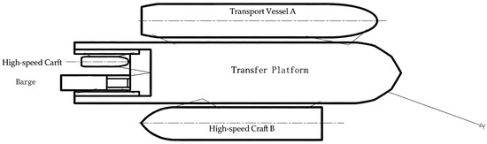
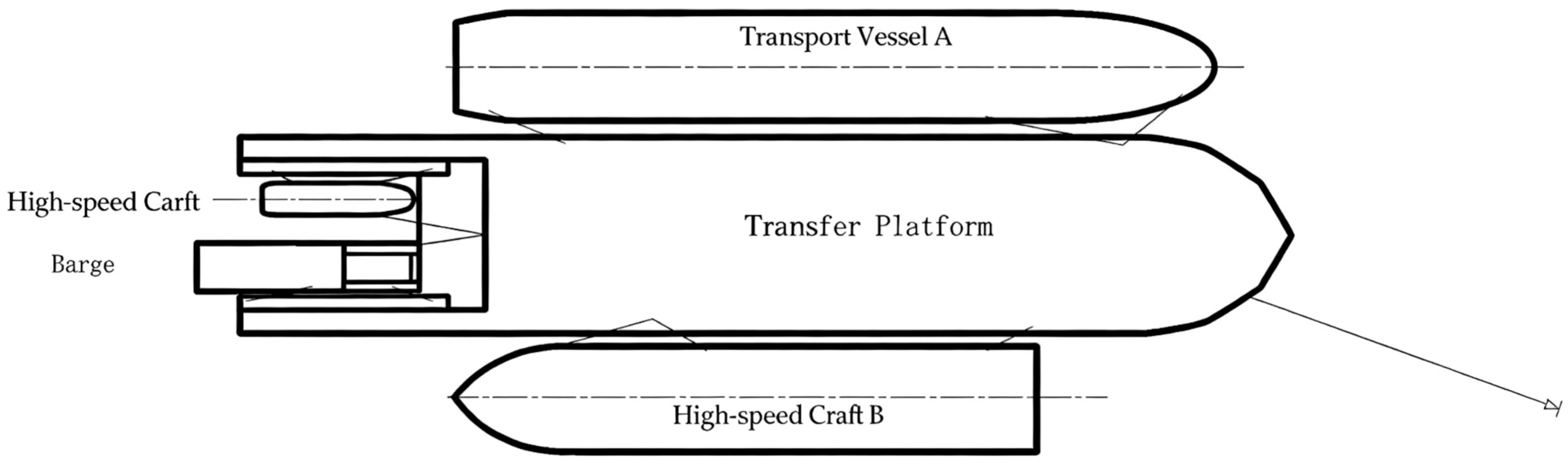
The experimental object is an offshore multi-body system. It is composed of one transfer platform, two transport ships, one high-speed craft, and one barge. See Table 1 for the principal particulars of each prototype vessel in the system.
Table 1.
Principal particulars of the prototype vessels.
The multi-body platform is a single-point mooring system, which uses the anchor system of the offshore platform to realize the mooring positioning. Mooring connections are arranged between adjacent floating bodies in the system, and the general layout is shown in Figure 1.
Figure 1.
Multi-body system.
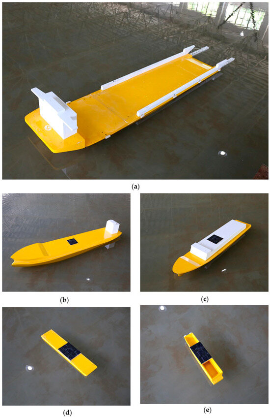
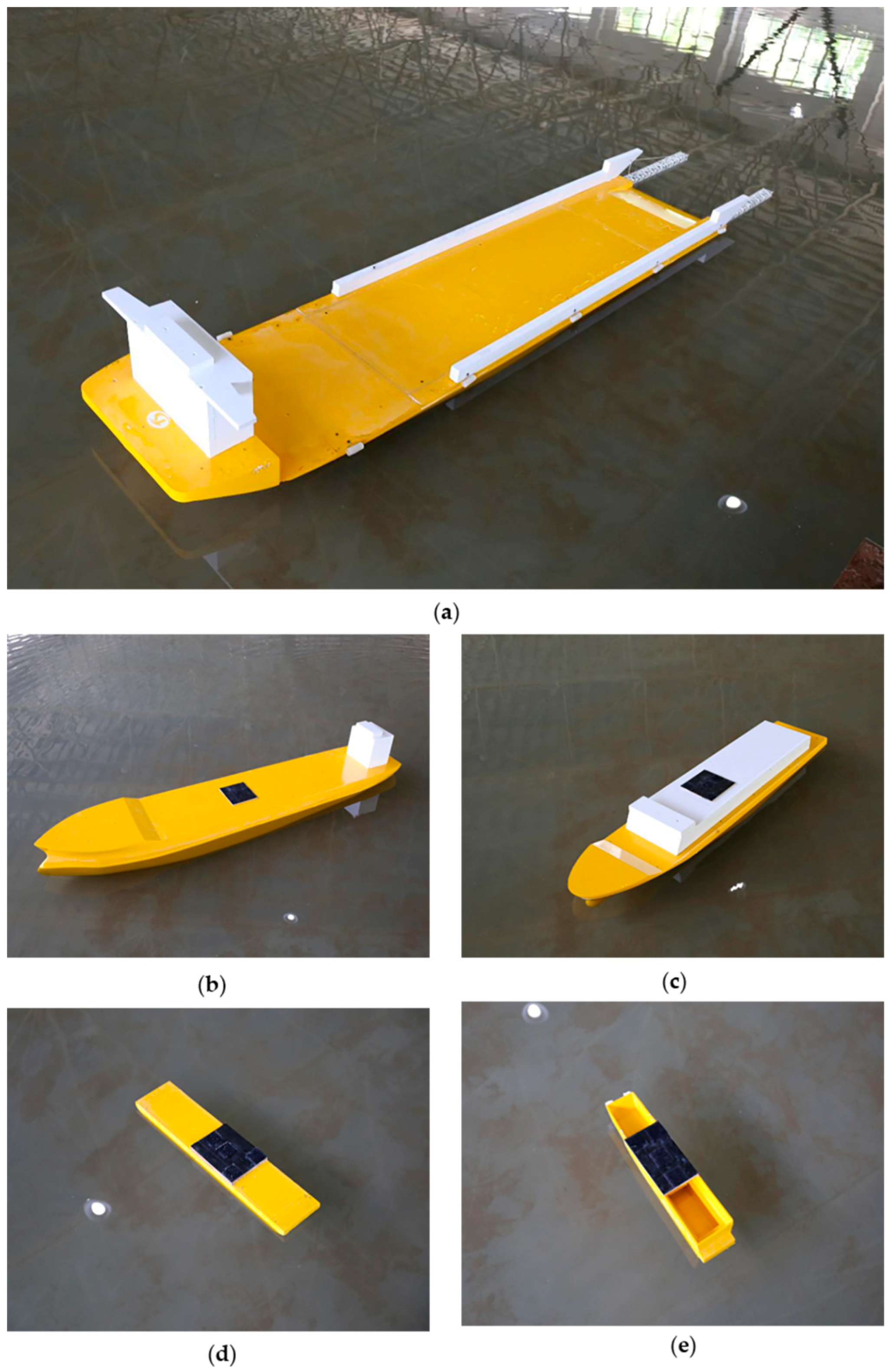
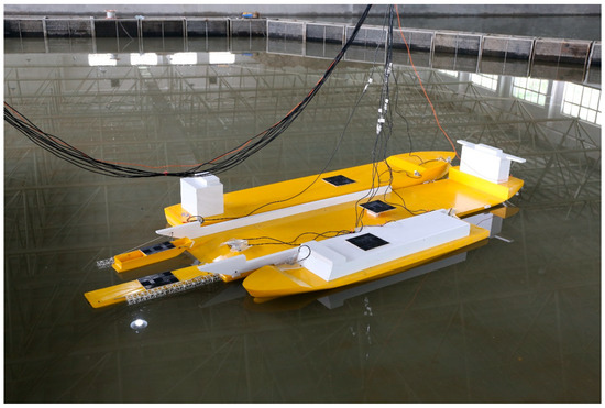
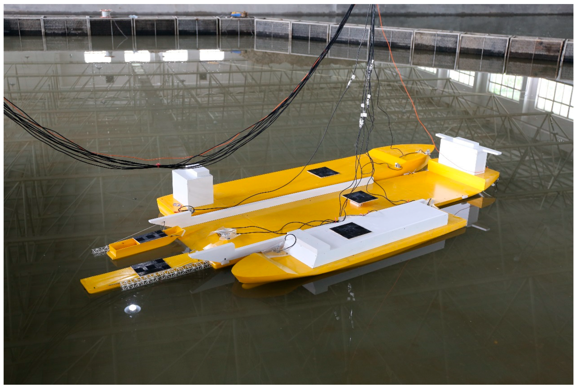
The scale ratio between the model and the actual ship is 1:50. The test models are shown in Figure 2 and Figure 3.
Figure 2.
(a) Transfer platform model; (b) Transport vessel A model; (c) Transport vessel B model; (d) Barge model; (e) High-speed craft model.
Figure 3.
Multi-body system model.
The transfer platform was single-point moored, while the other vessels were attached using mooring lines and fenders. Polypropylene mooring lines were used to connect adjacent vessels: a 60 mm diameter line (breaking strength 416 kN) with 2.0 t pretension was applied between the transport vessel B and the transfer platform, while 40 mm diameter lines (breaking strength 197 kN) with 1.0 t pretension were used for all other connections.
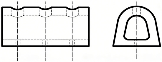
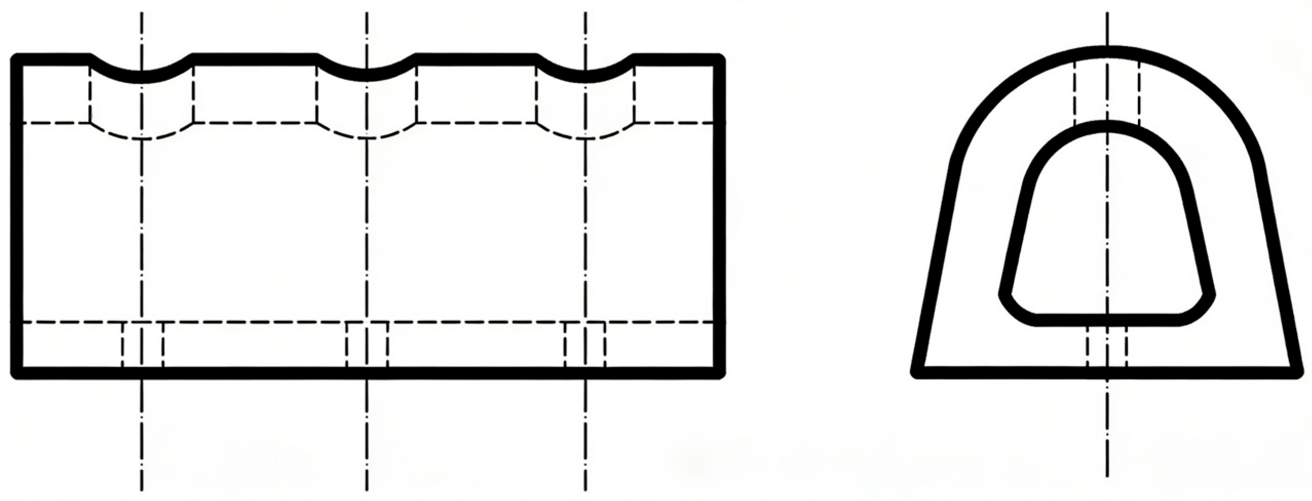
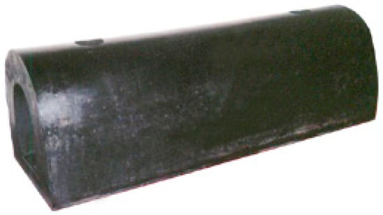
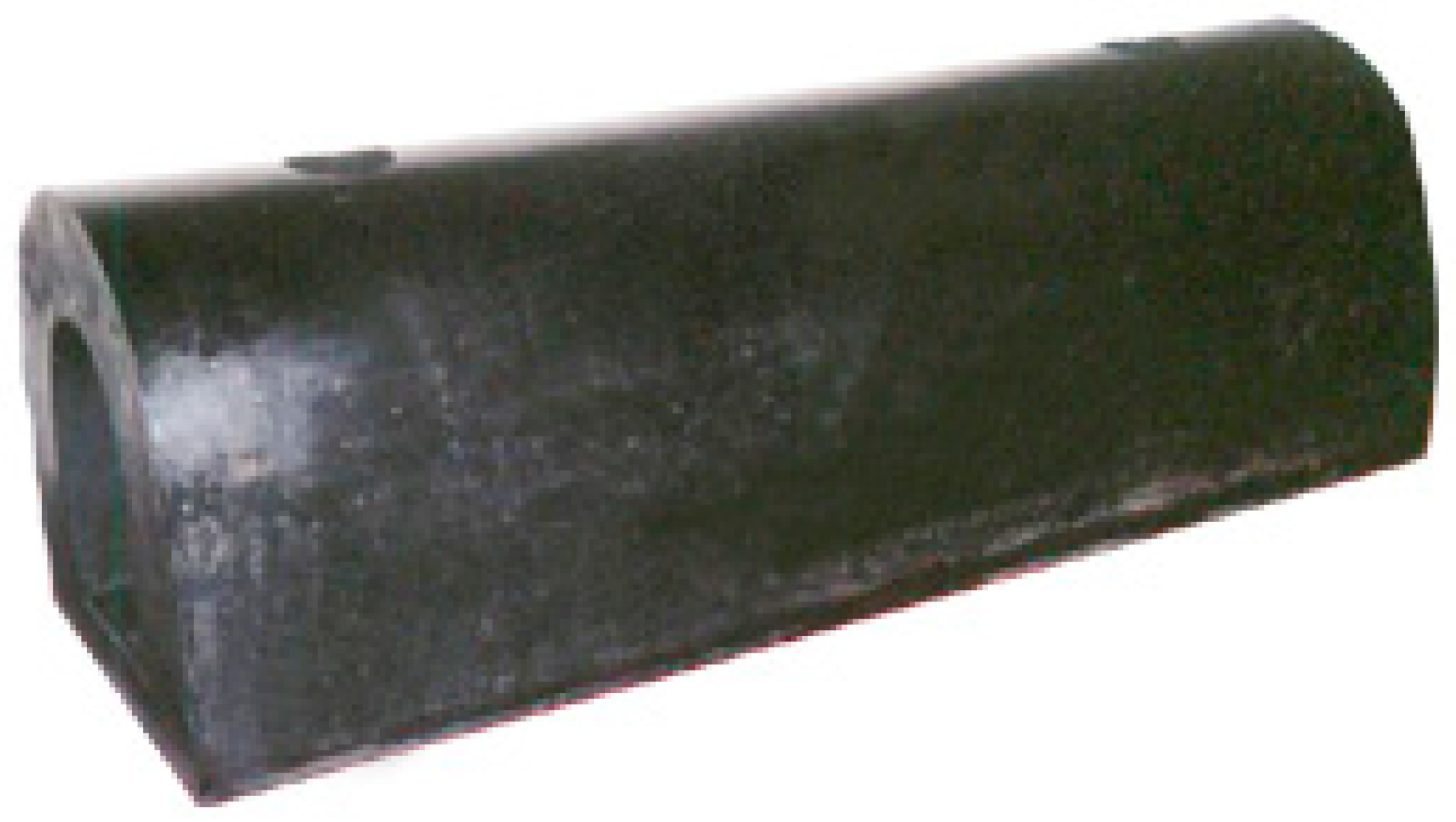
Fenders were installed at the contact positions: arch-type D400 × 400 × 1500 mm fenders (design force 564 kN) were used between the transport vessel B and the transfer platform, while D300 × 300 × 1500 mm fenders (design force 441 kN) were used for the other connections. Their nonlinear force–deformation relationships were reproduced at model scale using calibrated rubber elements. Figure 4 and Figure 5 show the fender models.
Figure 4.
Schematic diagram of the fender structure.
Figure 5.
Physical model of the fender.
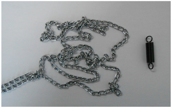
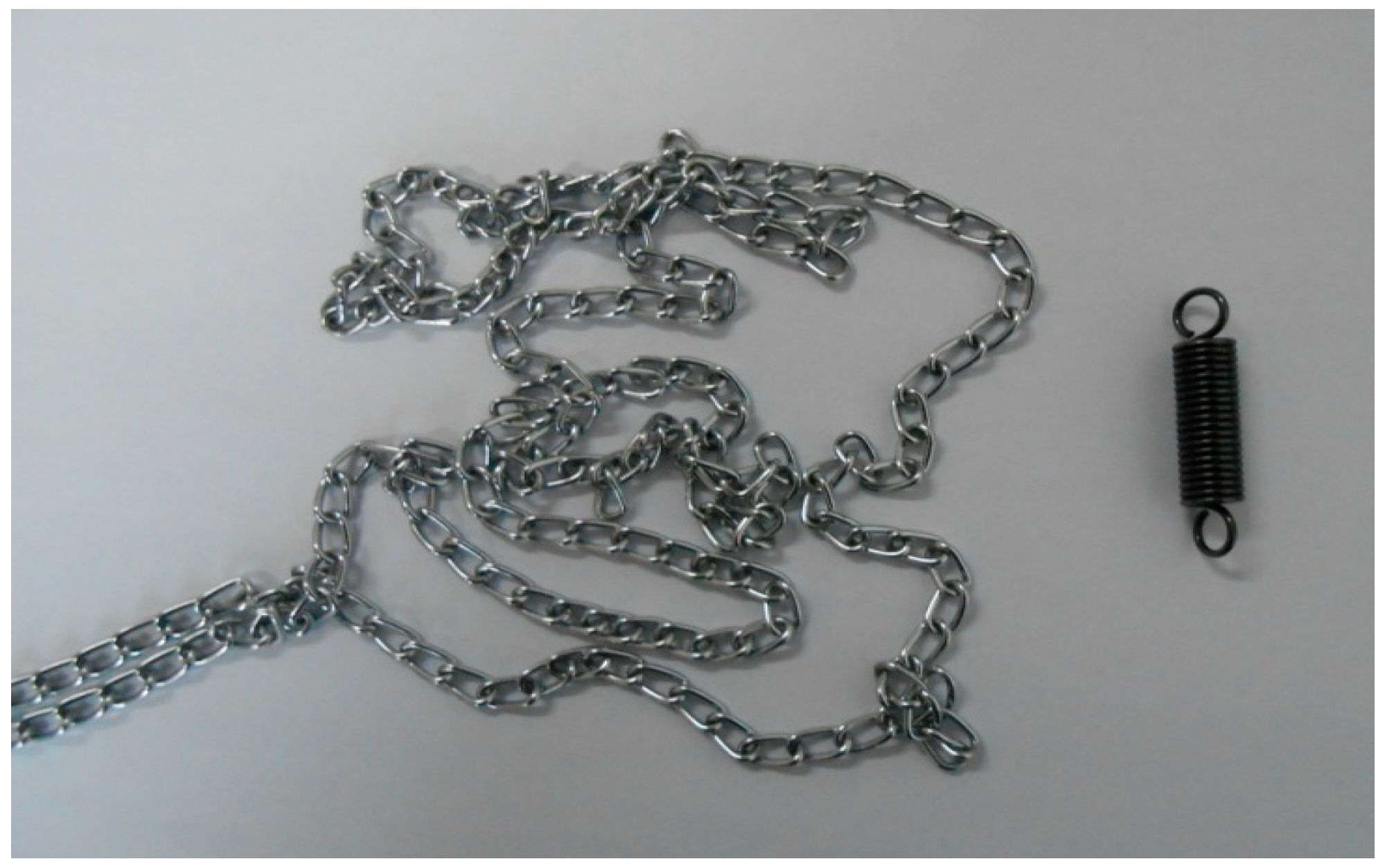
The offshore transfer system is a single-point mooring system, moored to the side of the transfer platform’s bow. The anchor chain was modeled using a combination of fine steel chains and calibrated springs to match the prototype’s stiffness–elongation characteristics. The physical properties of anchor chains are shown in Table 2 and the model is shown in Figure 6.
Table 2.
Physical properties of anchor chain.
Figure 6.
Anchor chain modeling using fine chains and calibrated springs.
The anchor chain modeling is shown in Figure 6. The prototype mooring chain had a length of 50 m, diameter of 60 mm, weight of 78.79 kg/m, and breaking strength of 2713.8 kN. In the model, the chain was simulated using fine steel chains (29.4 g/m) combined with calibrated springs to reproduce the prototype’s linear stiffness characteristics.
2.4. Experimental Facilities and Instrumentation
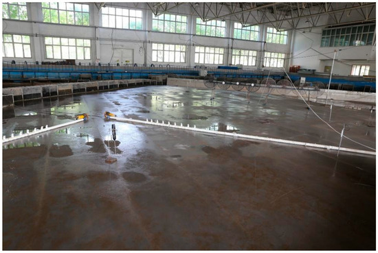
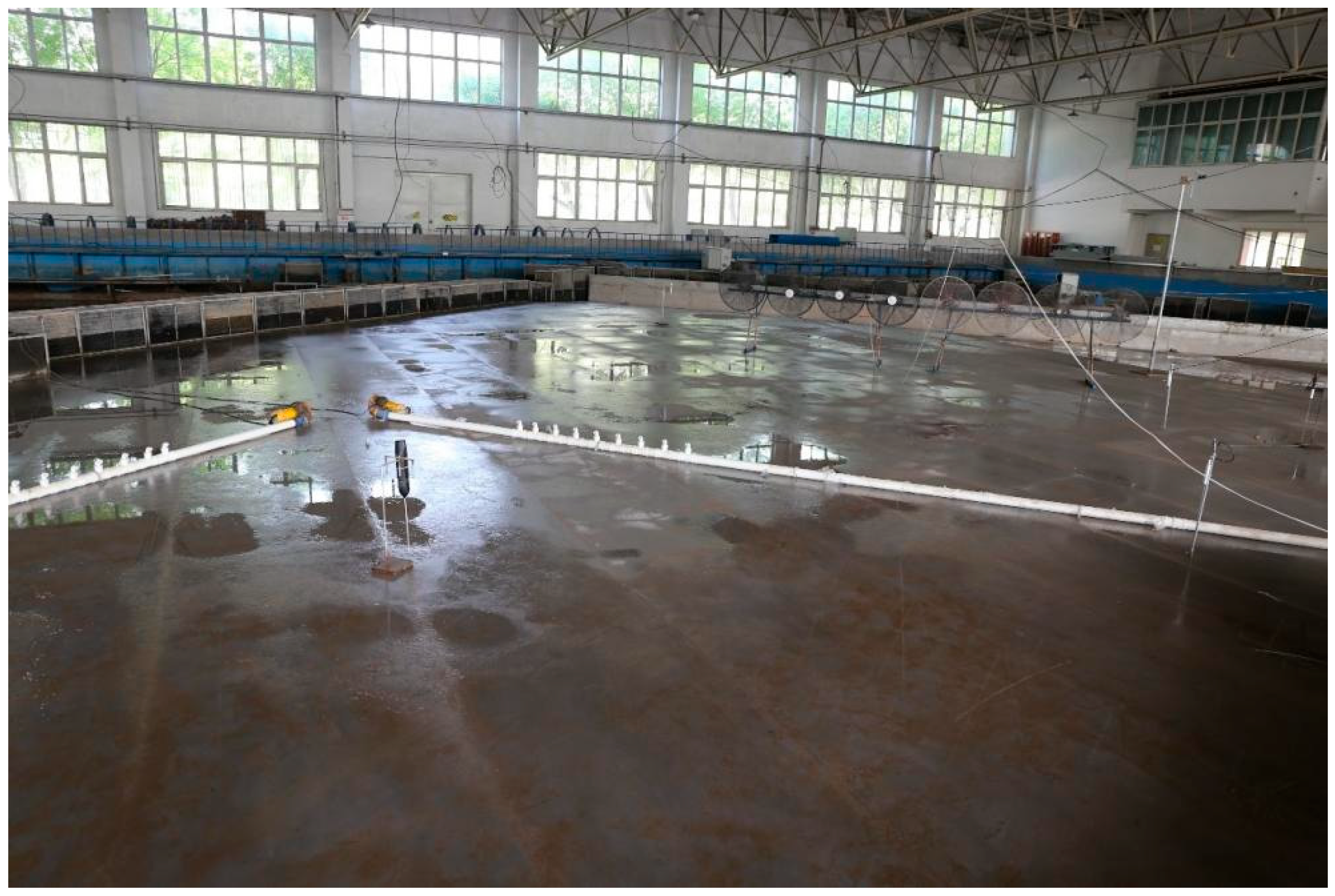
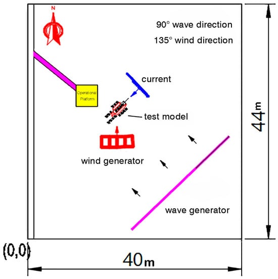
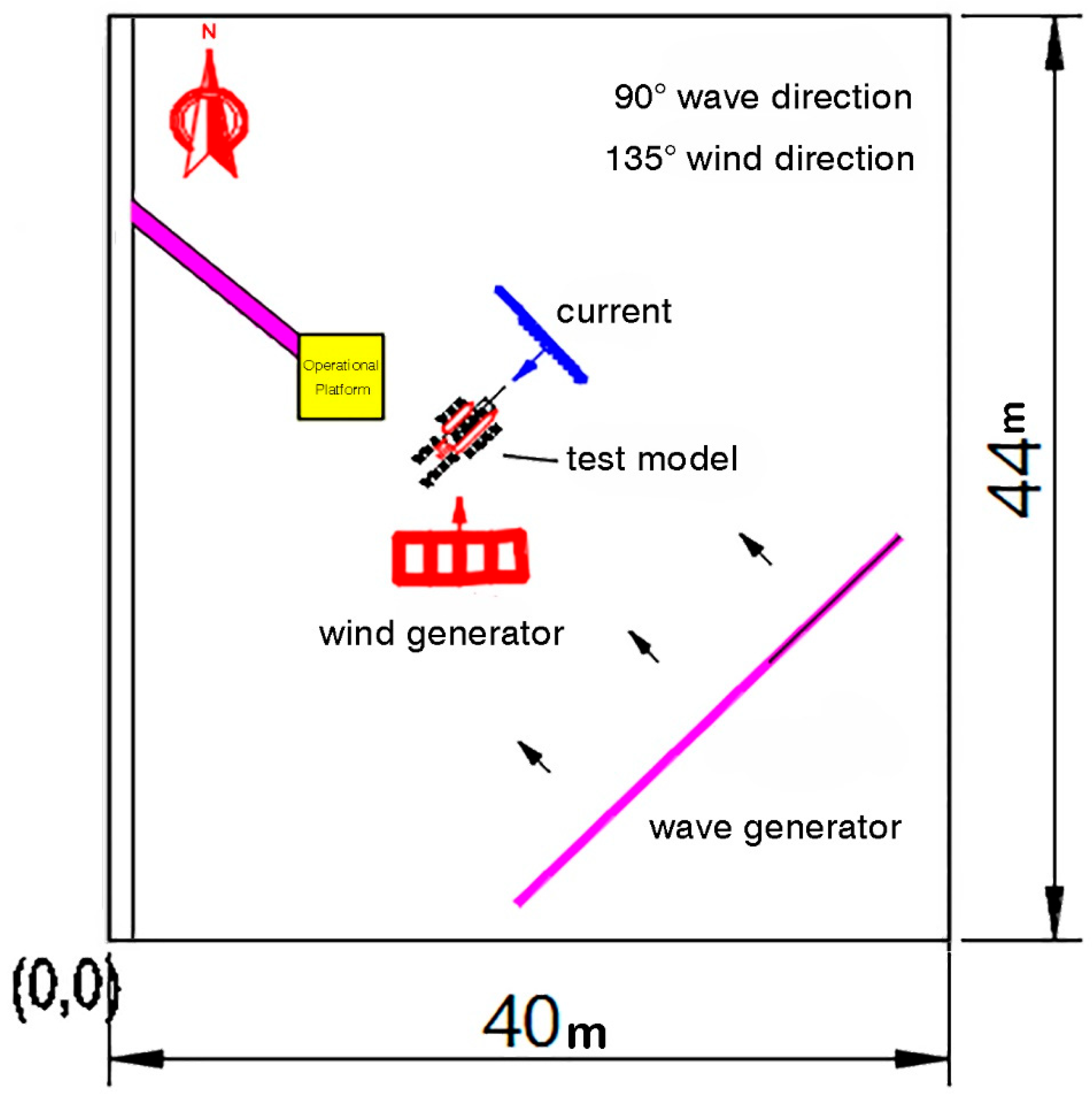
The tests were carried out in a rectangular basin of dimensions 44 m × 40 m, equipped with integrated wave, current, and wind generation systems. The basin was fitted with absorbing boundaries to minimize reflection and spurious interference. As shown in Figure 7.
Figure 7.
Experimental basin layout.
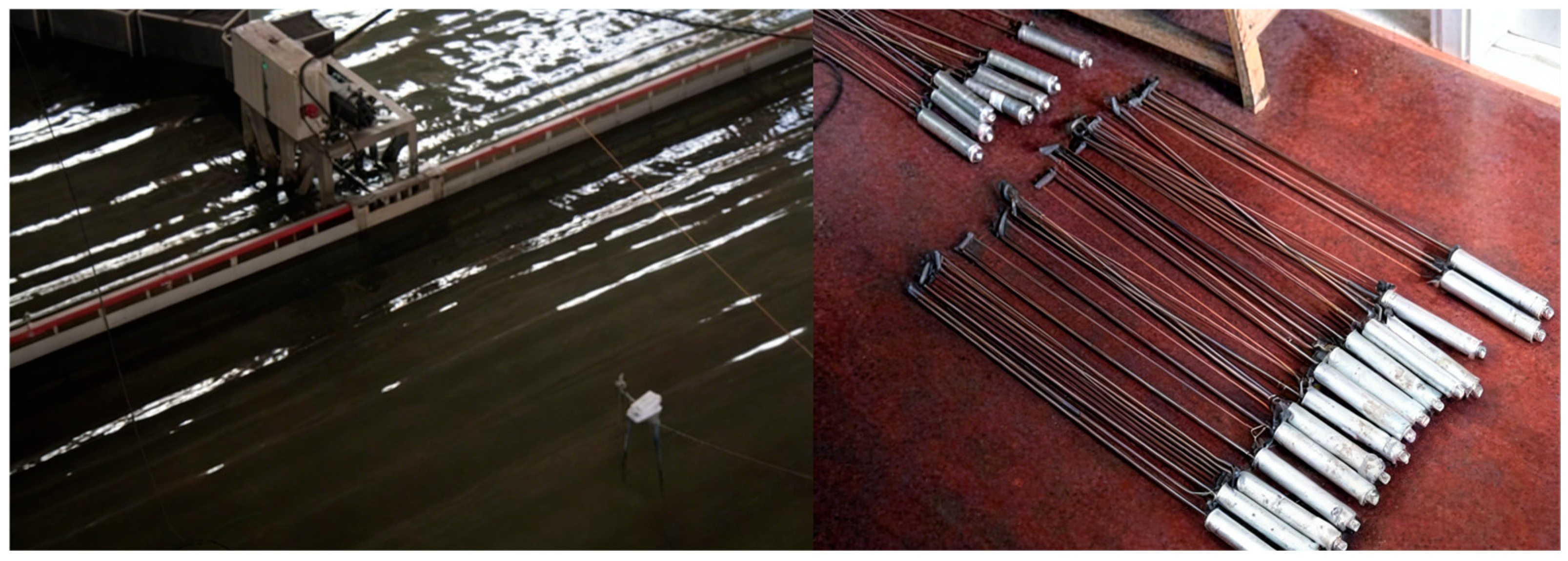
The wave generation and measurement system is shown in Figure 8. Irregular waves in the basin were generated by a movable wave maker, which allowed adjustment of both wave direction and location to reproduce diverse sea states. The system consisted of a wave board driven by a servo motor, servo controller, encoder, server, and a host computer with dedicated peripherals. Control signals for wave generation were computed in real time by the computer, transmitted to the servo driver, and executed by the servo motor to drive the wave board and produce the target wave conditions. Wave elevations were measured using the SG2000 wave acquisition system (Institute of Water Transport Engineering Science, Tianjin, China), which provides high-resolution monitoring of surface elevations. Prior to each test scenario, the generated waves were calibrated against the target spectrum using the measurement system to ensure accuracy and repeatability of the wave conditions.
Figure 8.
Movable irregular wave generator and wave elevation sensors.
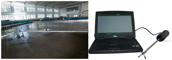
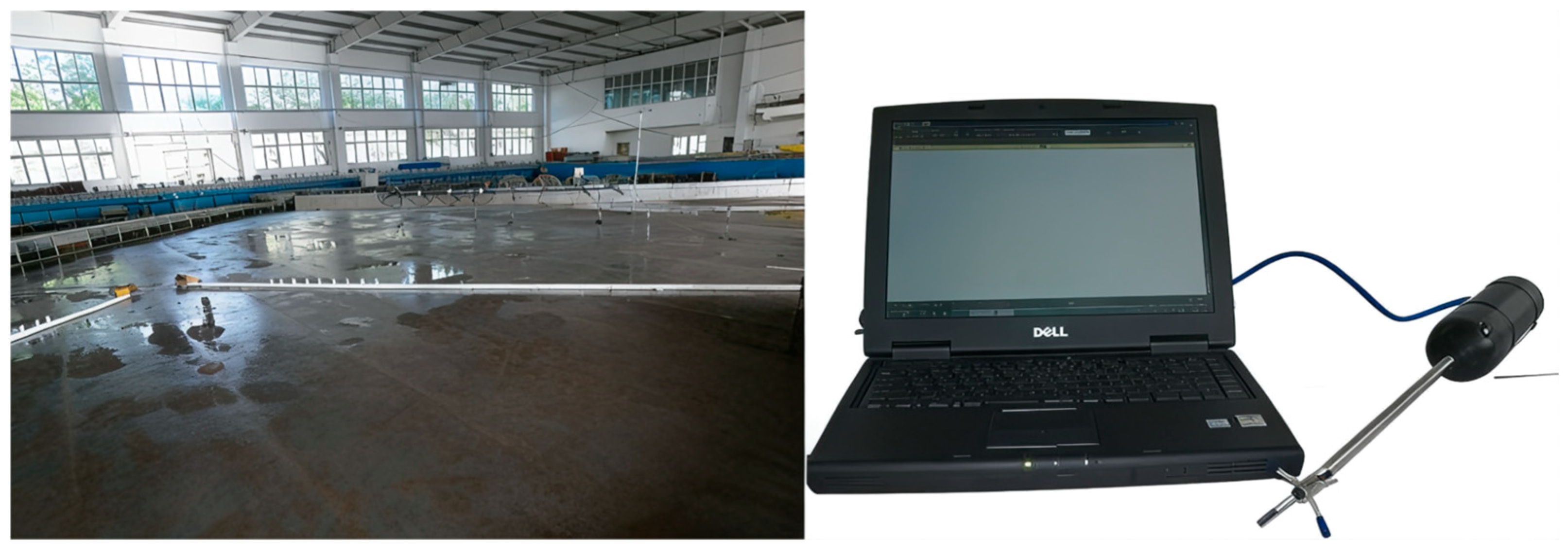
The current generation and measurement system is shown in Figure 9. The current field in the basin was produced using a localized pumping system, whereby water was injected into dedicated ducts to create controlled flow conditions. At a water depth of 0.3 m, the system was capable of generating a maximum depth-averaged velocity of approximately 0.3 m/s. The current-generation system was designed to operate independently of the wave-generation system, ensuring that the two subsystems did not interfere with each other during tests. The Doppler three-dimensional velocity measurement system (Nortek, Norway) was mainly used for data acquisition to measure the velocity of the pool. Before the test of each working condition, the velocity test system was employed to test and calibrate the velocity of the pool.
Figure 9.
Basin current-generation pump and NDV high-precision acoustic Doppler velocimeter.
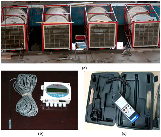
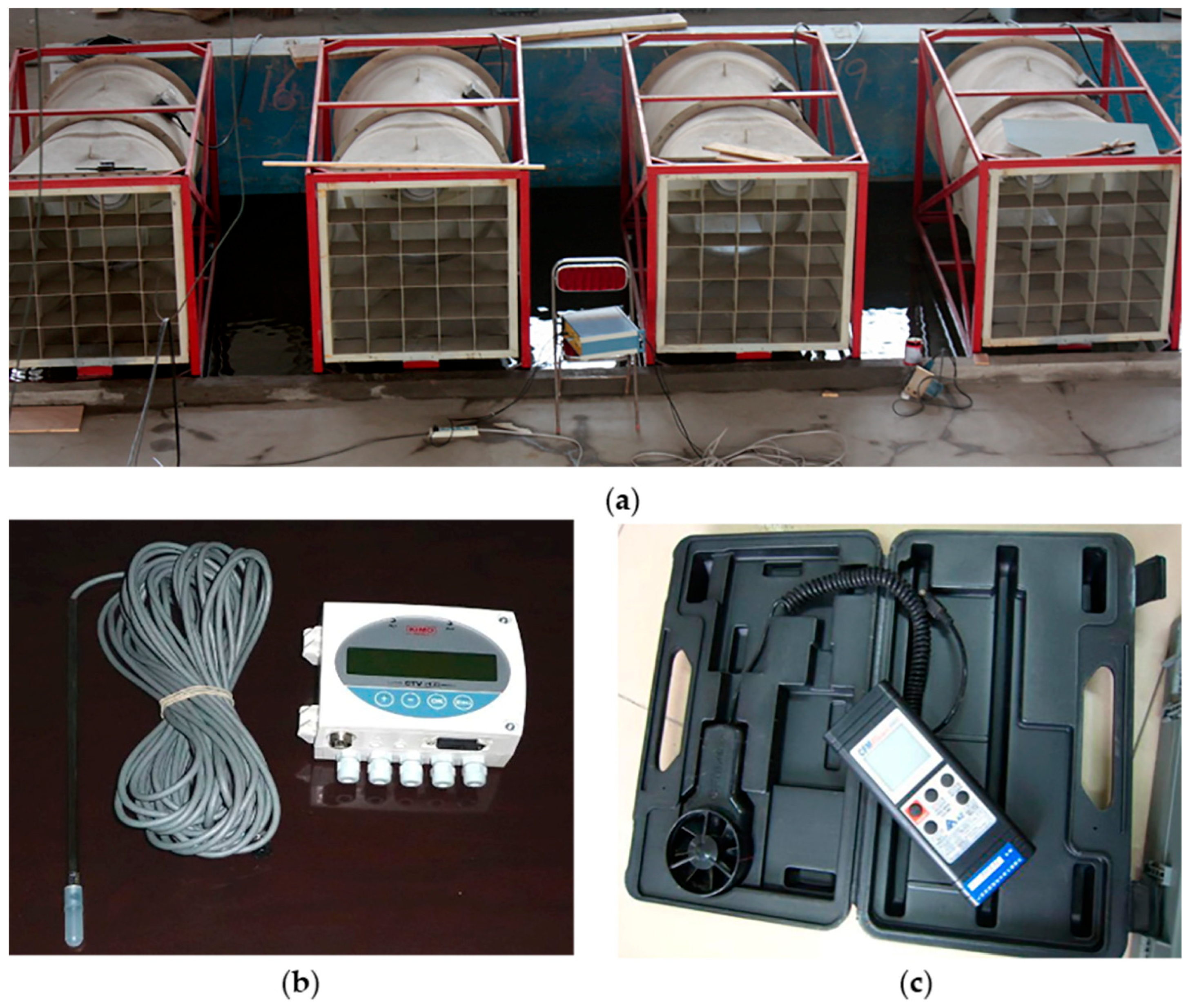
The wind generation and measurement system is shown in Figure 10. The wind generation system was composed of a series of independently controlled fans, which could move to change the wind direction. The wind speed was controlled by frequency conversion, and the maximum wind speed could reach 10.0 m/s. Wind velocity was monitored using hot-wire anemometers (CEM Instruments Co., Shenzhen, China). Before the test of each working condition, the wind speed test system was calibrated.
Figure 10.
(a) Wind generation system; (b,c) Data acquisition equipment.
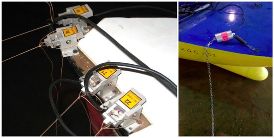
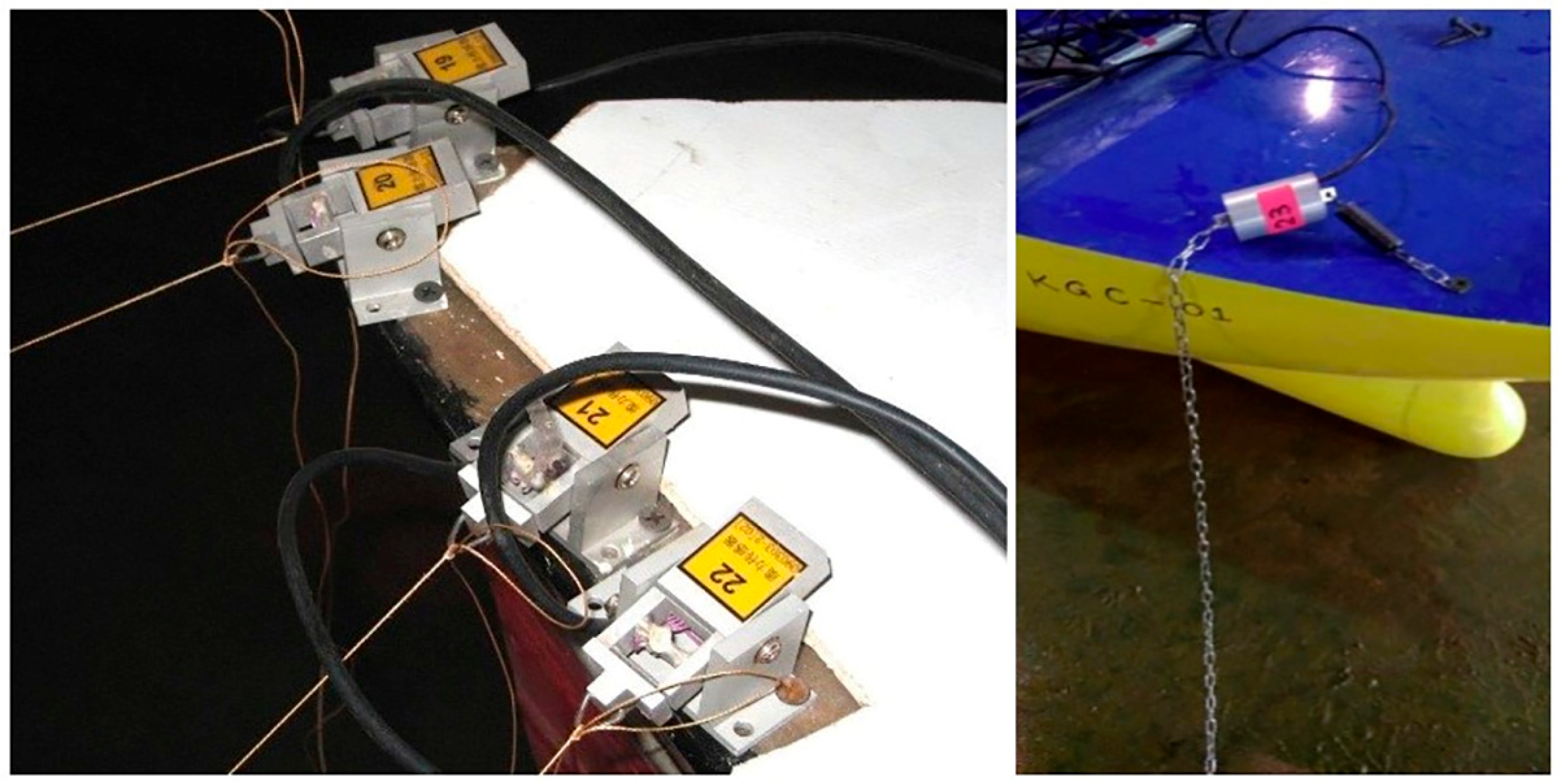
In this experiment, the mooring force was primarily measured using the comprehensive testing system for hydrodynamic forces on factory ship models, as illustrated in Figure 11.
Figure 11.
Integrated hydrodynamic force measurement system for ship models.
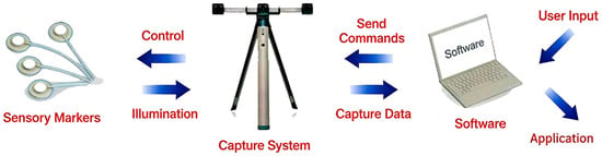
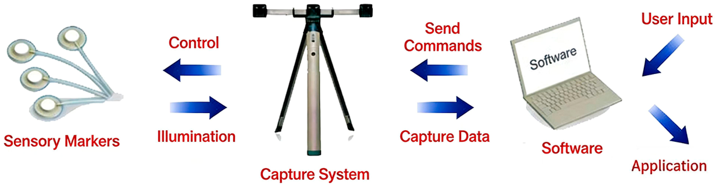
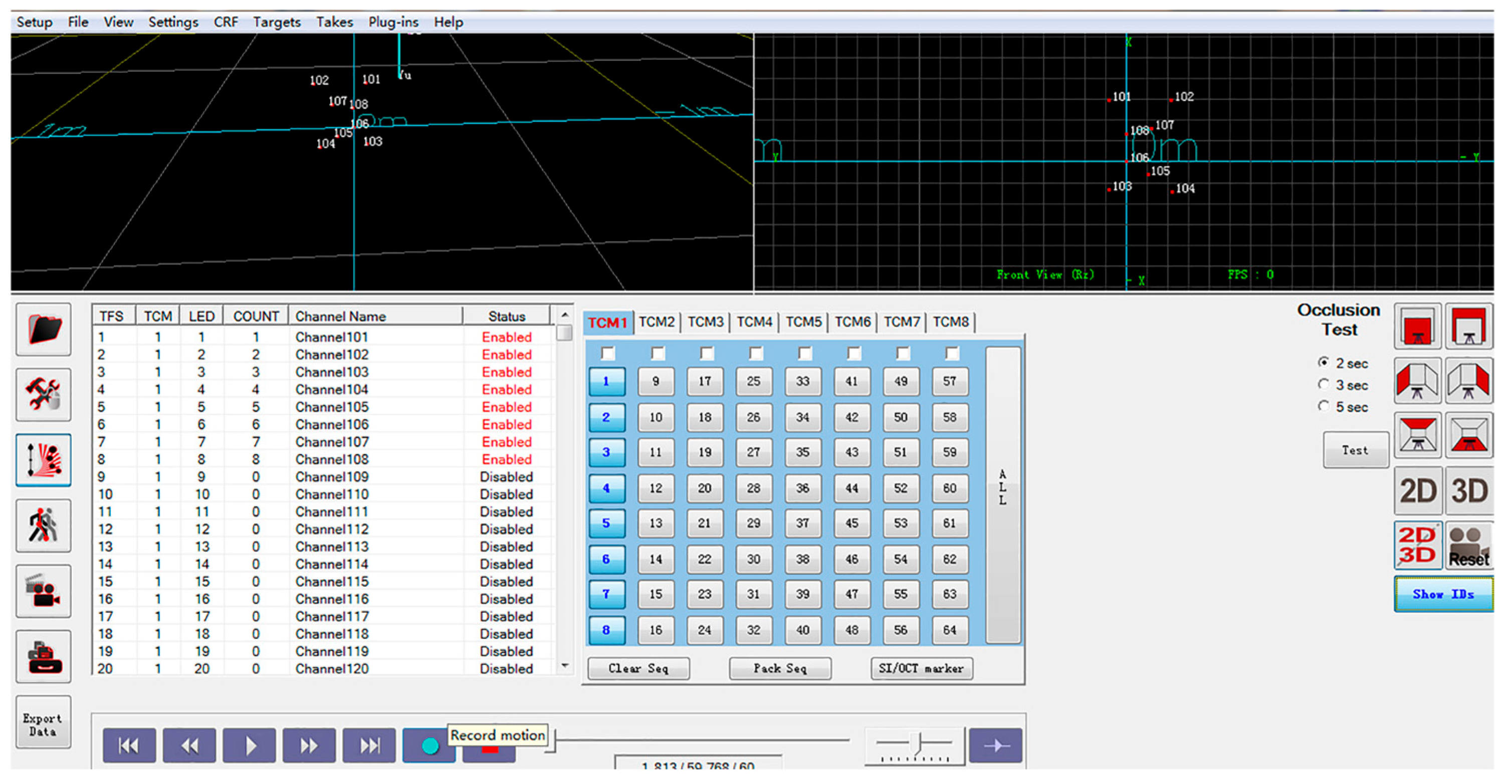
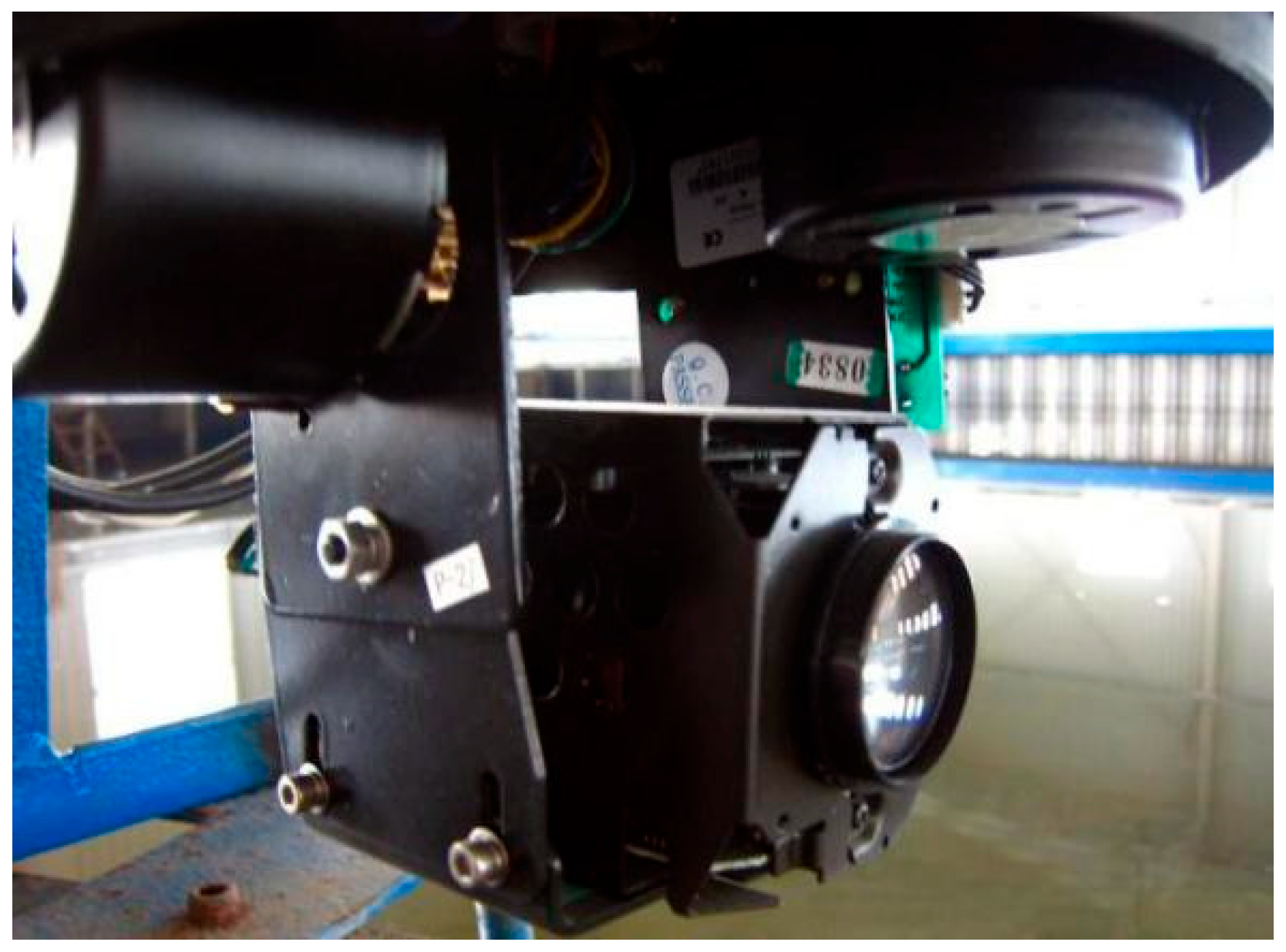
In this test, a Canadian PTI three-dimensional optical tracking system (Northern Digital Inc., Waterloo, ON, Canada) is used for ship motion capture, as shown in Figure 12 and Figure 13. The system uses the principle of optical positioning to measure the movement of the ship, and is composed of multiple cameras, signal transmitter, receiver and dedicated data acquisition software (NDI 6D Architect Version 3.2.1). It provides a measurement volume of up to 190 m3, with a spatial accuracy of 0.015 mm. The system is capable of tracking up to 512 independent ID markers simultaneously, with a maximum sampling frequency of 10,000 Hz. Each camera covered a capture range of approximately 7 × 9 × 9 m, ensuring that the six degrees of freedom (6-DoF) motions of all ship models could be accurately and continuously monitored during the tests.
Figure 12.
Optical motion capture system.
Figure 13.
Motion acquisition software interface.
The lab-assembled digital video cameras and still cameras were employed throughout the experiments to document test conditions and vessel responses. As shown in Figure 14, these devices provided continuous visual records that complemented the quantitative measurements, enabling post-test verification of system performance and qualitative analysis of hydrodynamic interactions.
Figure 14.
Digital video camera used for experimental documentation.
To ensure the reliability of the experimental results, all measurement systems were carefully calibrated prior to testing. The motion capture system provides a spatial accuracy of up to 0.015 mm, ensuring high-resolution measurement of six-degree-of-freedom motions. Wave elevation measurements were validated against the target spectrum before each test case, while wind and current velocities were calibrated using standard measurement procedures.
Repeatability tests were conducted under selected representative conditions, showing consistent results with negligible variation in key motion parameters. The overall experimental uncertainty is considered to be within an acceptable range for hydrodynamic model testing. Potential sources of error include scaling effects associated with Froude similarity, residual wave reflections in the basin, and minor deviations in environmental condition generation. These effects were minimized through calibration and controlled experimental procedures.
2.5. Test Conditions and Layout
The test program simulated offshore operating conditions in terms of water depth, waves, wind, and currents.
Prototype water depth was 10 m. Wave conditions were defined using the JONSWAP spectrum with significant heights Hs = 0.8, 1.0, 1.5, 2.0 m and mean zero-crossing periods Tp between 4.0 and 5.94 s. Wind conditions were steady velocities of 10.7 m/s and 17.1 m/s at 10 m height. A uniform current of approximately 3 knots was applied in all cases.
The environmental conditions adopted in the present experiments were selected to represent typical offshore operational scenarios rather than extreme design conditions. The wave heights and periods were defined based on commonly encountered sea states in moderate offshore environments, ensuring the relevance of the results to practical replenishment operations. The selected wind speeds correspond to operational limits under which offshore transfer activities can still be safely conducted, while the current velocity reflects typical background flow conditions observed in coastal and nearshore regions.
The sea wave spectrum adopts the JONSWAP spectrum, with the expression as follows:
In the formula:
- S(f)—wave spectral density (m2·s)
- f—wave frequency (Hz)
- Hs—significant wave height (m)
- Tp—spectral peak period (s)
- fp—spectral peak frequency (Hz) fp = 1/Tp
- γ—peak enhancement factor
- σ = 0.07 for f ≤ fp and σ = 0.09 for f > fp
In addition, the combination of multiple wave headings and wind directions was designed to capture representative loading scenarios, including head, beam, and oblique conditions, which are known to induce significantly different hydrodynamic responses in multi-body systems. This approach allows for a systematic evaluation of the coupled effects of wind, wave, and current under realistic operating conditions.
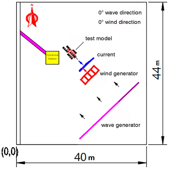
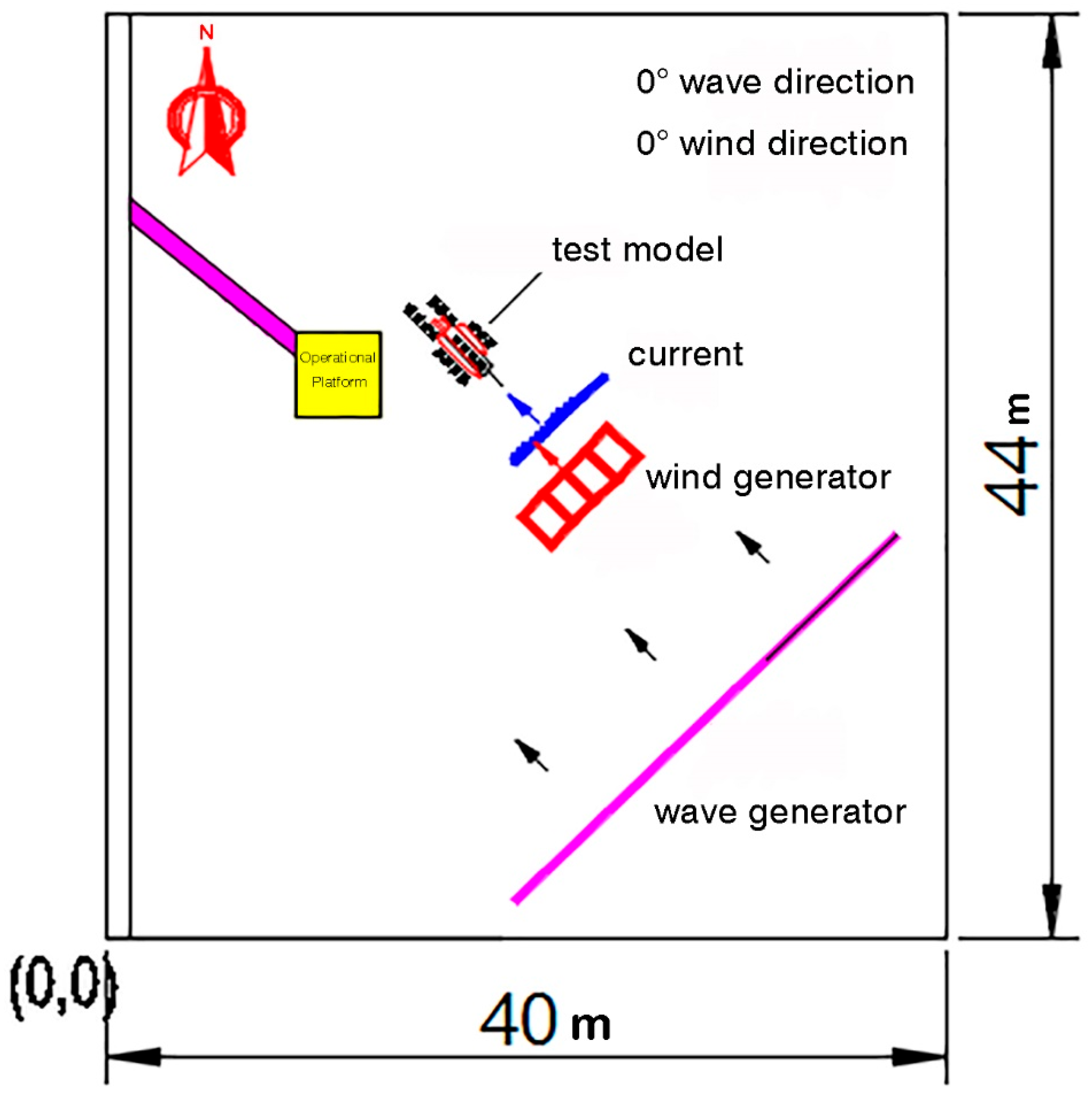
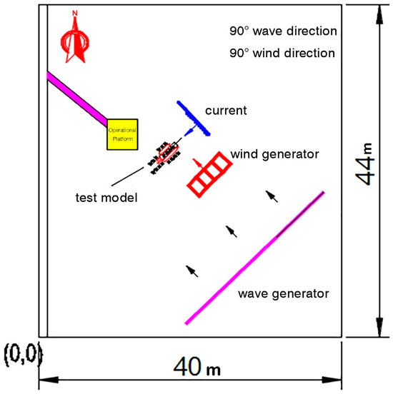
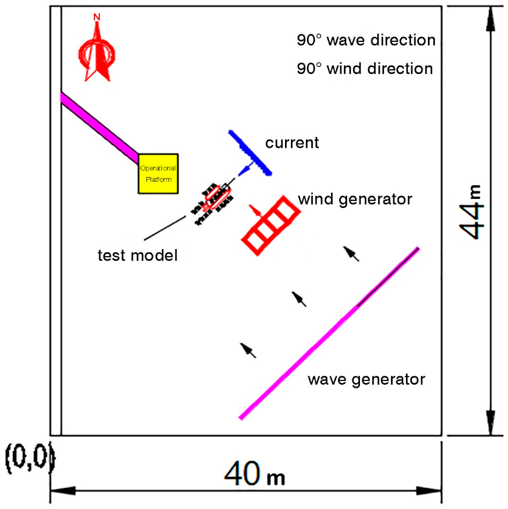
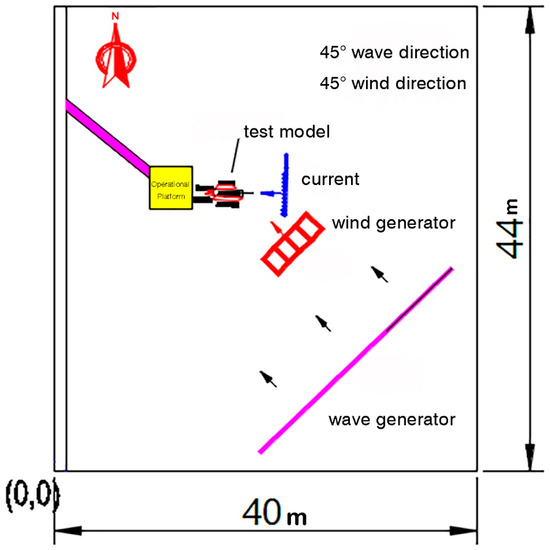
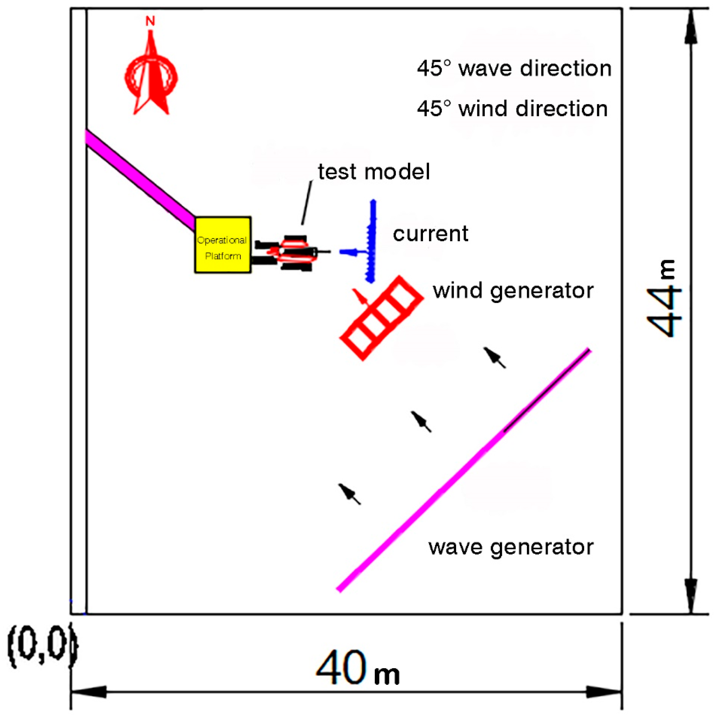
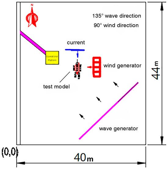
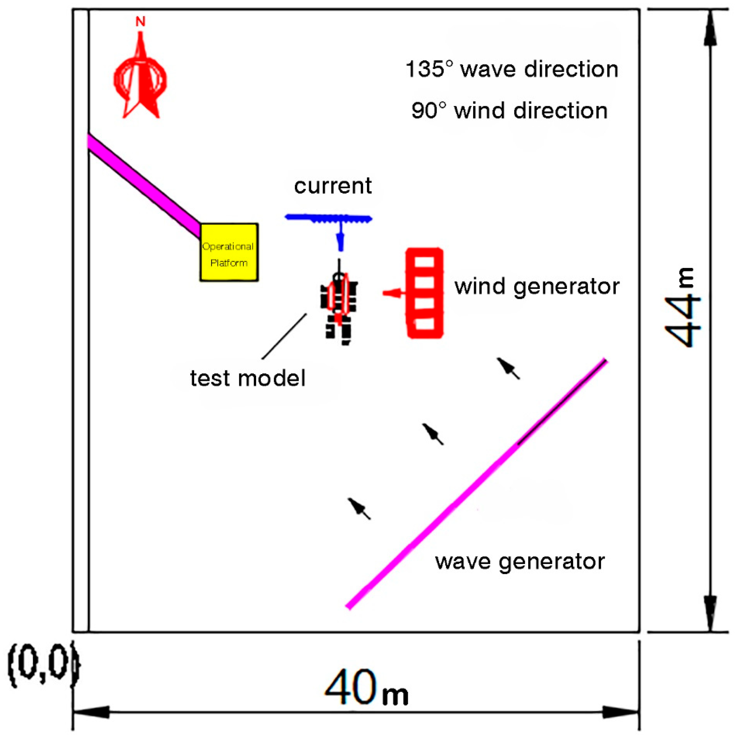
For the present tests, a right-handed coordinate system was adopted in which the head-on direction of the vessel was defined as 0°, and the starboard beam direction as 90°, with headings increasing clockwise. To capture the representative influence of different approach angles, four incident wave directions were selected: head seas (0°), quartering seas (45°), beam seas (90°), and stern-quartering seas (135°). Among the oblique headings, 45° and 135° were chosen, as these conditions provide the largest projected hydrodynamic area and produce the most pronounced motions, while reducing the total number of cases without losing representativeness. In total, five combined wind–wave–current cases were examined, with the current direction fixed at 0° while varying the relative headings of waves and wind. The corresponding experimental layouts are illustrated in Figure 15, Figure 16, Figure 17, Figure 18 and Figure 19.
Figure 15.
Experimental layout under 0° wave direction and 0° wind direction.
Figure 16.
Experimental layout under 90° wave direction and 90° wind direction.
Figure 17.
Experimental layout under 45° wave direction and 45° wind direction.
Figure 18.
Experimental layout under 135° wave direction and 90° wind direction.
Figure 19.
Experimental layout under 90° wave direction and 135° wind direction.
3. Results
This section presents the experimental observations of the multi-body floating system under five representative combined wind–wave–current conditions. The results are organized into two categories: (i) absolute motions of each unit in six degrees of freedom (surge, sway, heave, roll, pitch, and yaw), and (ii) relative motions between the central transfer platform and the companion vessels.
3.1. Absolute Motions
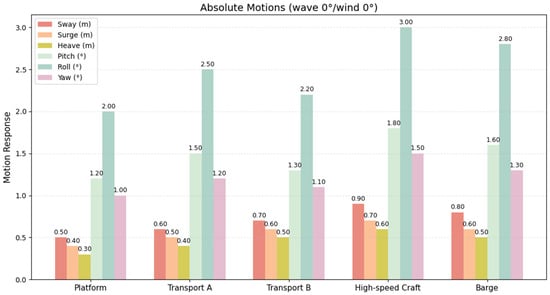
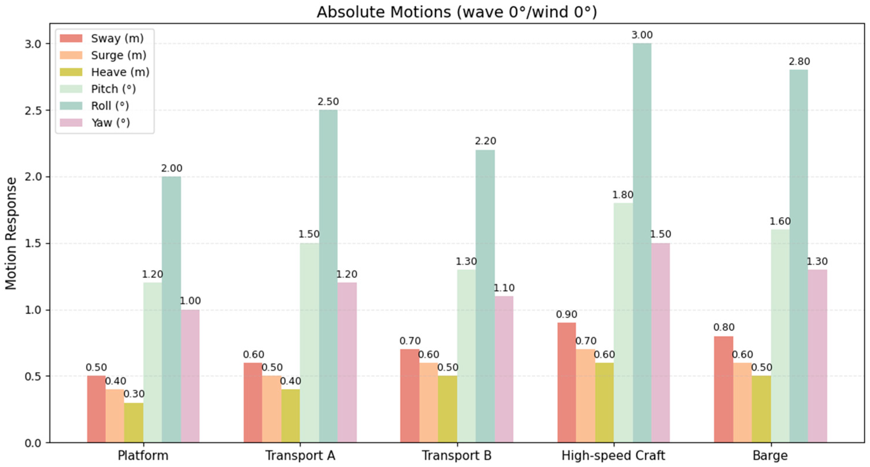
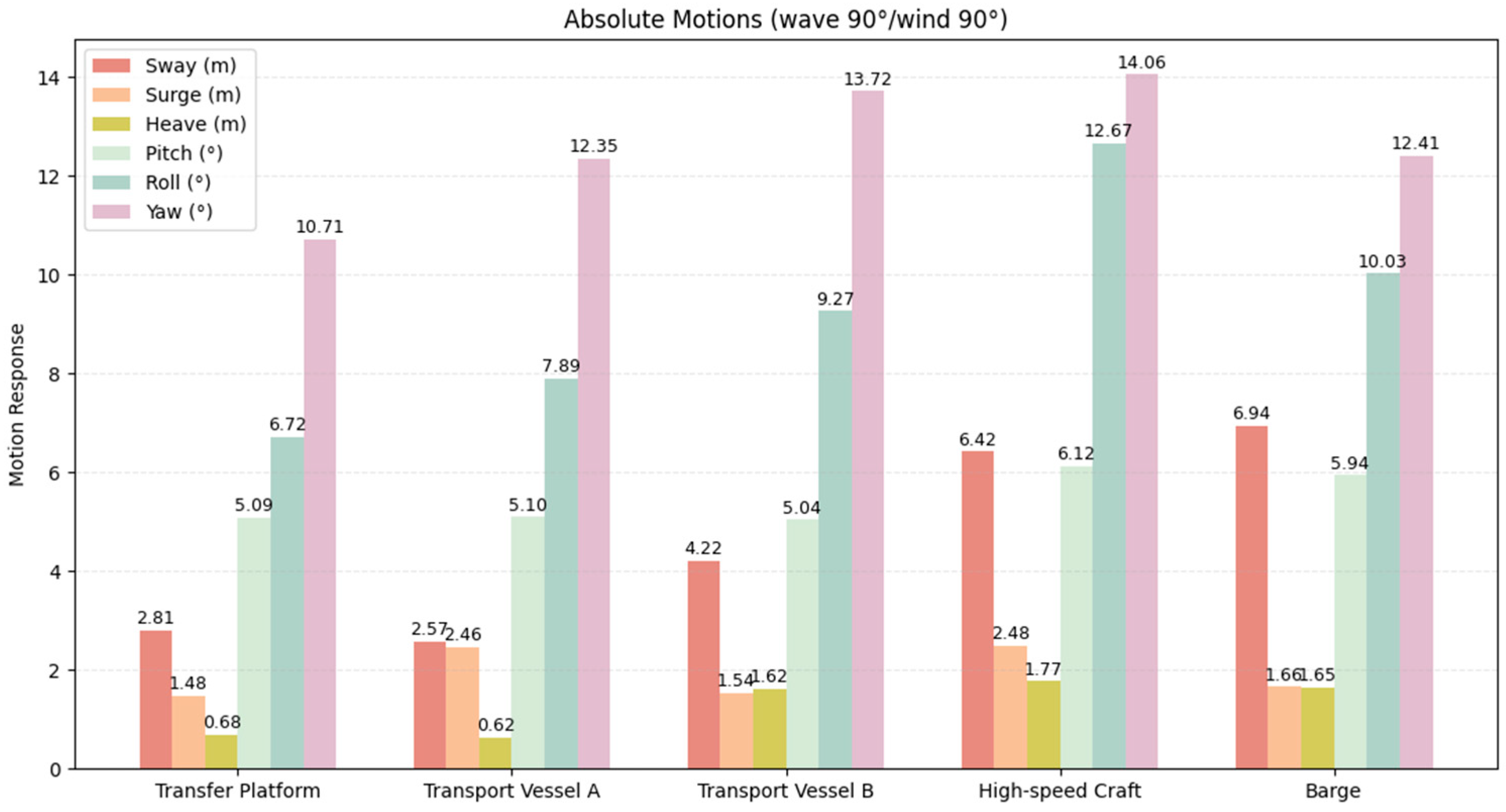
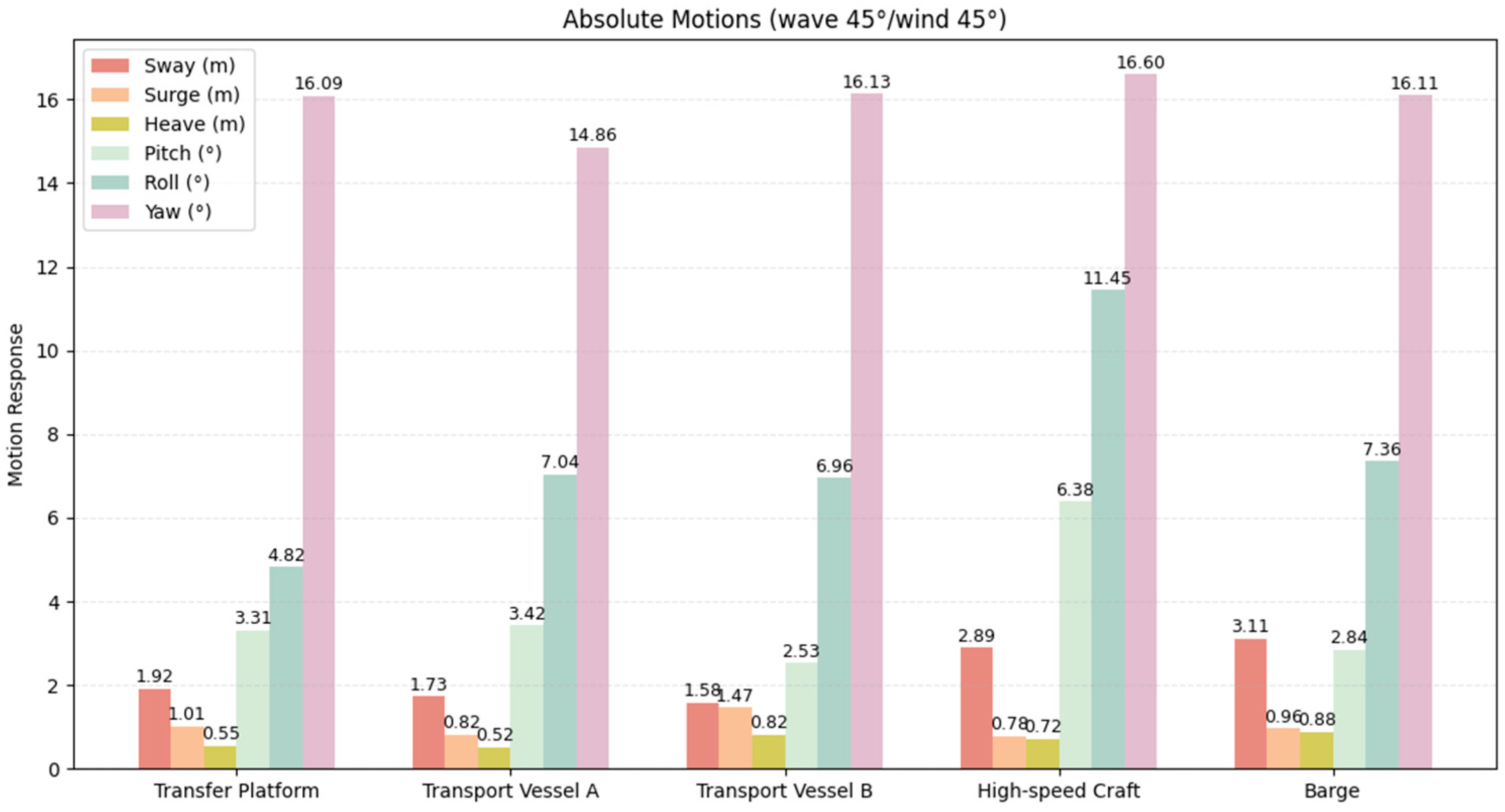
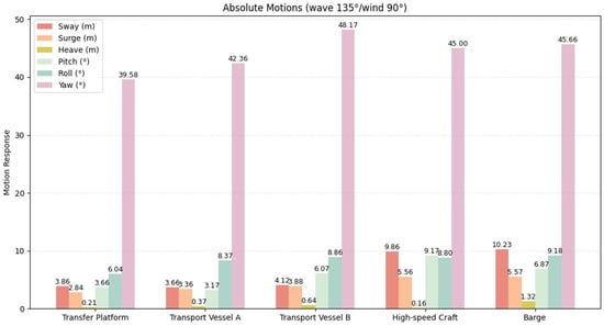
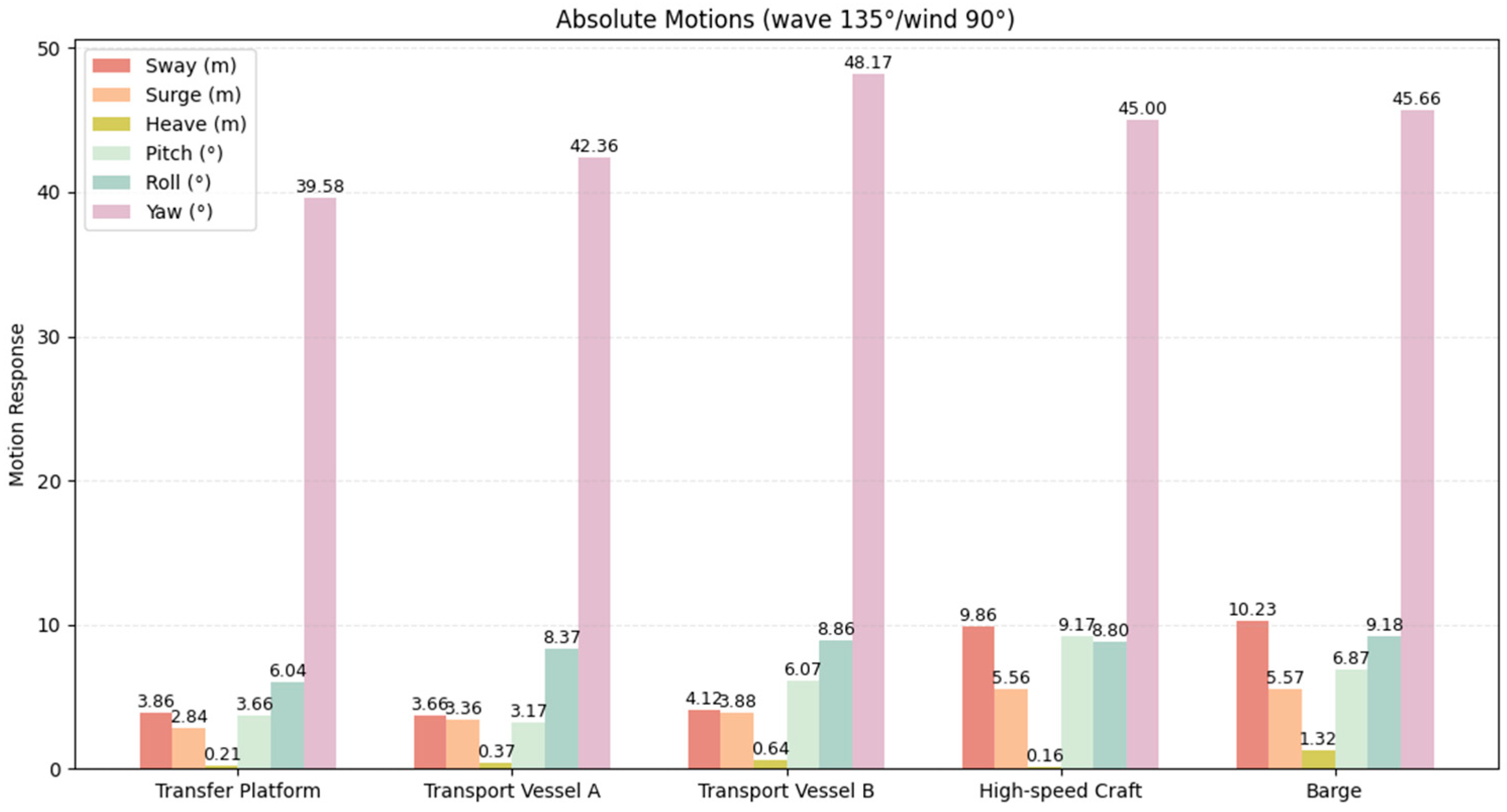
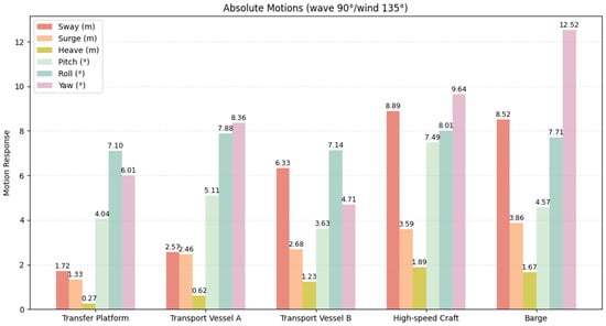
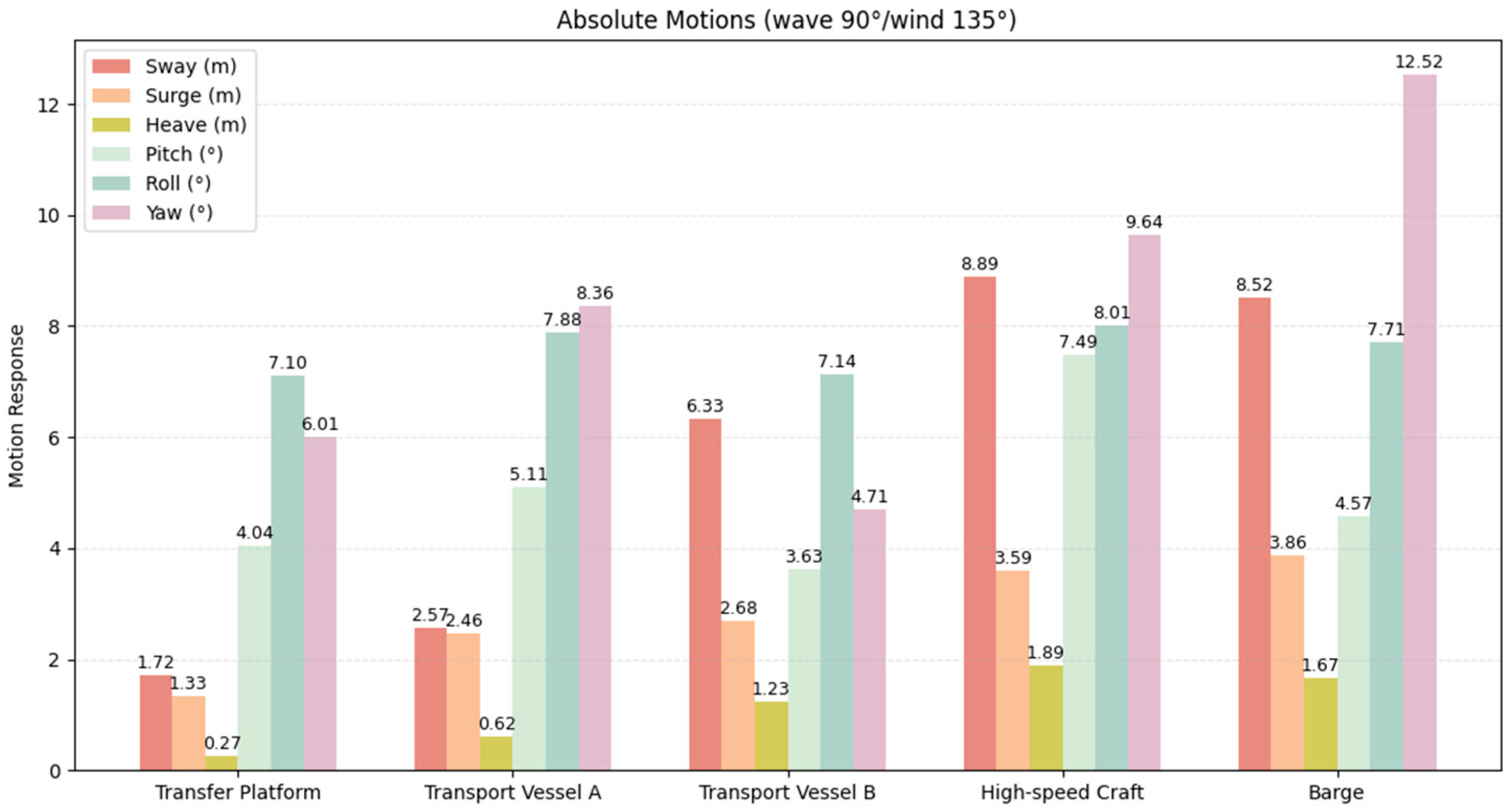
This section reports the measured motions of each floating unit under the five combined wind–wave–current cases. The results are visualized in Figure 20, Figure 21, Figure 22, Figure 23 and Figure 24, which illustrate maximum values for each motion component.
Figure 20.
Maximum motions of all vessels under 0° wave and 0° wind conditions.
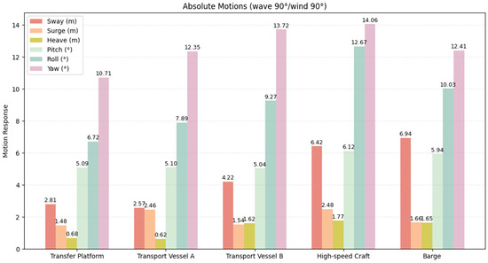
Figure 21.
Maximum motions of all vessels under 90° wave and 90° wind conditions.
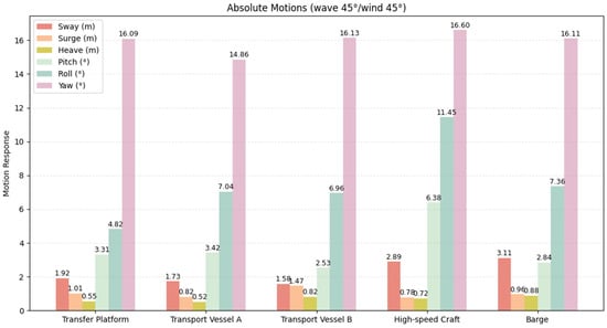
Figure 22.
Maximum motions of all vessels under 45° wave and 45° wind conditions.
Figure 23.
Maximum motions of all vessels under 135° wave and 90° wind conditions.
Figure 24.
Maximum motions of all vessels under 90° wave and 135° wind conditions.
3.1.1. Sway
Significant differences in sway response are observed among the floating units and loading cases. The overall maximum sway is recorded for the barge, reaching 10.23 m under 135° waves combined with 90° wind (Figure 23). Under the same condition, the high-speed craft exhibits a comparable but slightly smaller sway amplitude of 9.86 m (Figure 23). A similarly large value (9.90 m) is also observed for the high-speed craft under 0° waves + 0° wind (Figure 20).
For Transport Vessel A, the maximum sway is 4.42 m, occurring under head seas (0° waves + 0° wind, Figure 20). Transport Vessel B shows its largest sway of 6.33 m under 90° waves + 135° wind (Figure 24). The transfer platform experiences comparatively smaller lateral excursions, with a maximum sway of 3.86 m under 135° waves + 90° wind (Figure 23). Overall, the outer vessels show the most pronounced sway motions under oblique and stern-quartering wave conditions, whereas the central transfer platform exhibits comparatively smaller lateral responses.
3.1.2. Surge
The data indicate that under the combined action of a 135° wave direction and a 90° wind direction, the surge response of the barge is most significant, with a maximum value of 5.57 m (Figure 23). The high-speed craft also exhibits almost the same motion amplitude, with a value of 5.56 m. This suggests that in a multi-body system, the outer units are more sensitive to oblique wind and wave conditions.
Under the conditions of 135° waves + 90° wind, the maximum surge amplitude of the Transport Vessel A is 3.36 m, and in the same case, the transfer platform reaches a peak surge of 2.84 m (Figure 23). In contrast, the transport vessel B exhibits its largest surge response under head seas, with a maximum value of 4.43 m occurring at 0° waves + 0° wind (Figure 20), rather than in oblique wave conditions.
3.1.3. Heave
Heave motions remain moderate across all vessels and loading cases when compared with horizontal motions. The overall maximum heave amplitude is 1.89 m, observed for the high-speed craft under 90° waves + 135° wind (Figure 24). The barge also shows relatively large heave responses, reaching 1.67 m under the same condition.
For the remaining units, heave amplitudes are generally below 1.3 m, with limited variation among different wave and wind directions. Compared with sway and surge, the sensitivity of heave to environmental directionality is less pronounced.
3.1.4. Pitch, Roll, Yaw
Among the rotational motions, the maximum pitch angle is recorded for the high-speed craft, reaching 9.17° under 135° waves + 90° wind (Figure 23). Roll motion is most significant under beam-sea conditions, with a maximum roll of 12.67° observed for the high-speed craft at 90° waves + 90° wind (Figure 21).
Yaw motion exhibits the largest amplitudes in oblique and stern-quartering seas. The overall maximum yaw angle is 48.17°, occurring for the transport vessel B under 135° waves + 90° wind (Figure 23). Other units also show increased yaw responses in this condition, though with smaller magnitudes.
In general, beam and oblique wave directions tend to amplify roll and yaw motions, while pitch responses are more sensitive to stern-quartering wave conditions, particularly for lighter and more compliant units.
3.2. Relative Motions
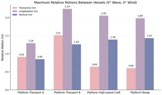
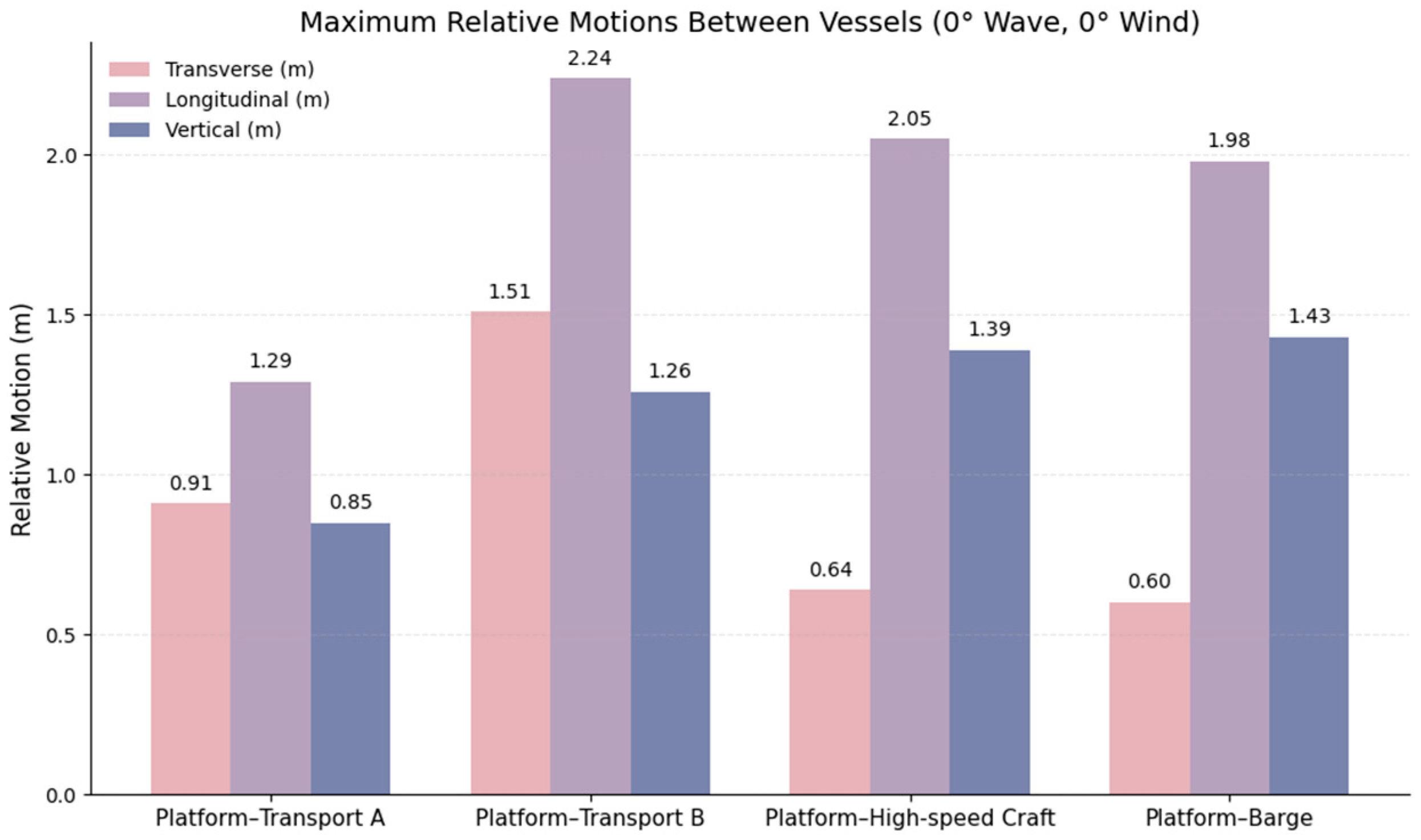
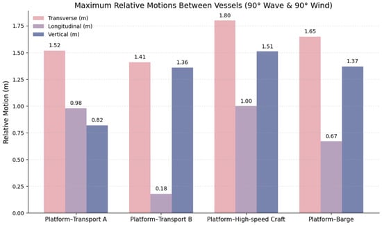
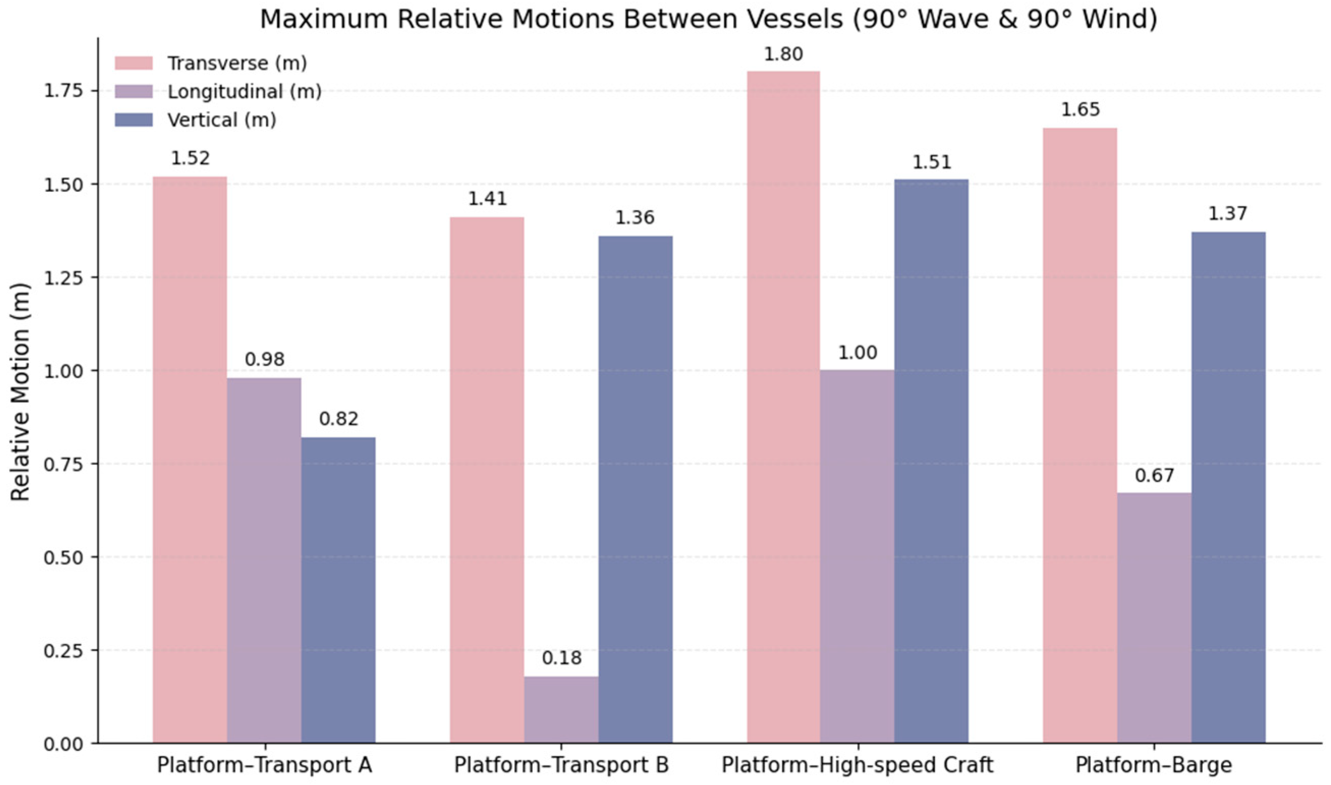
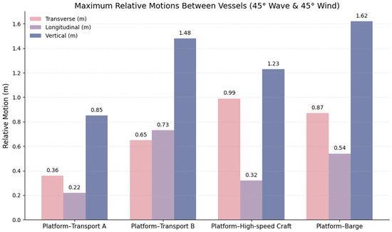
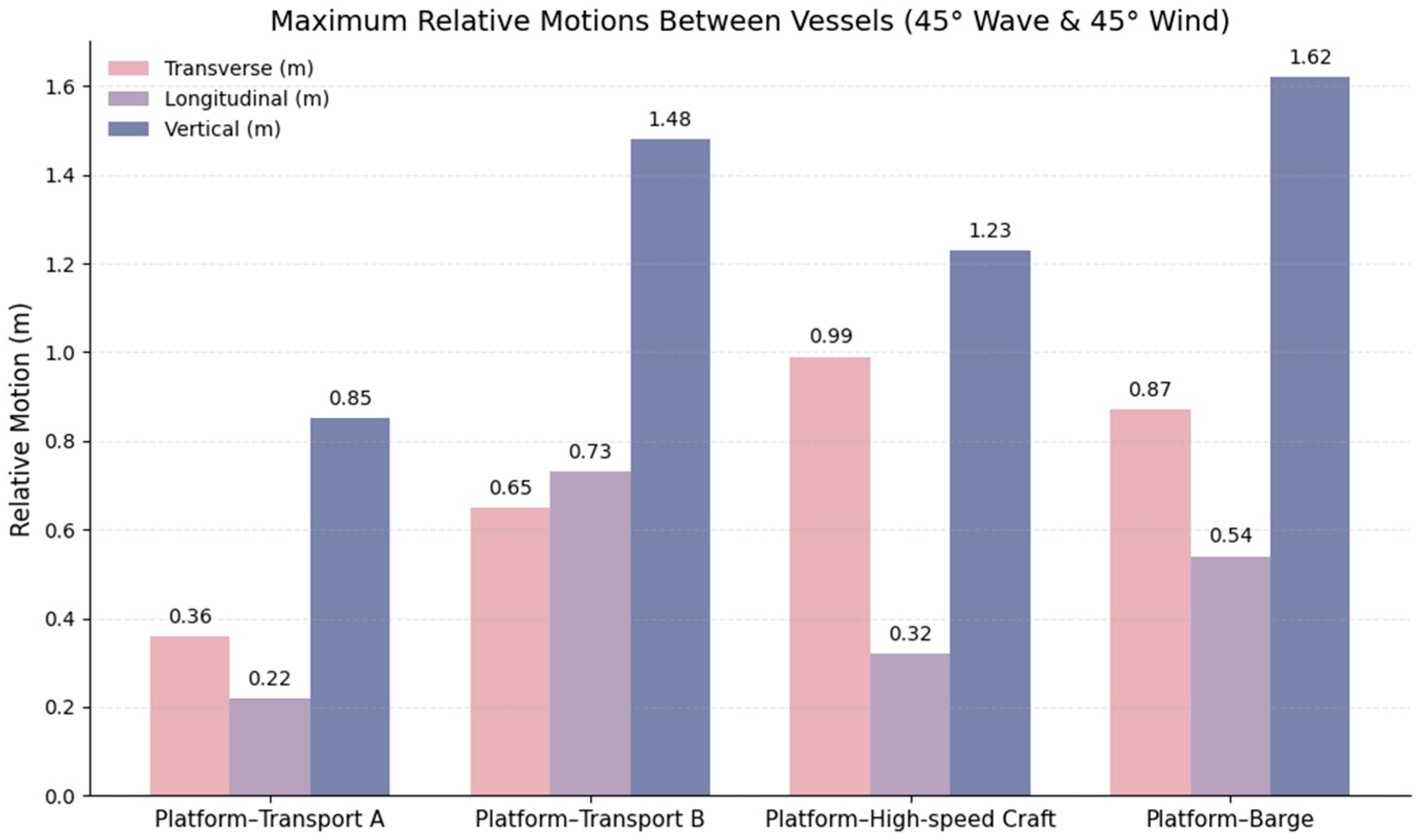
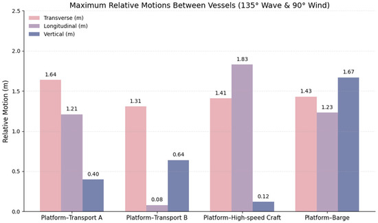
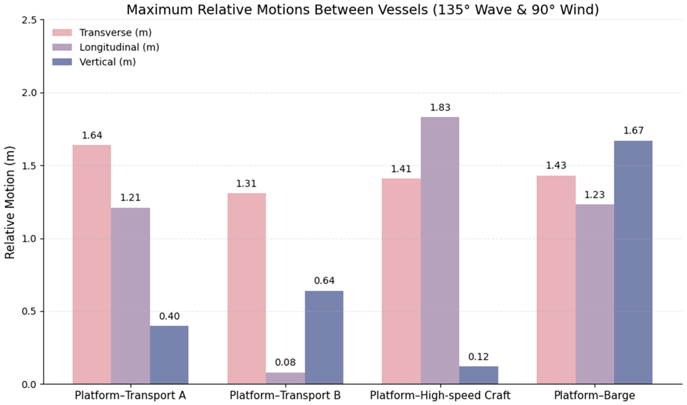
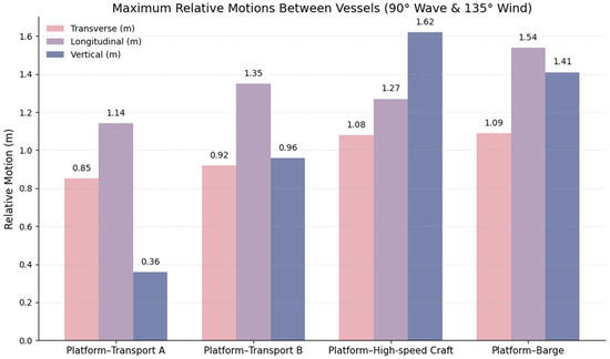
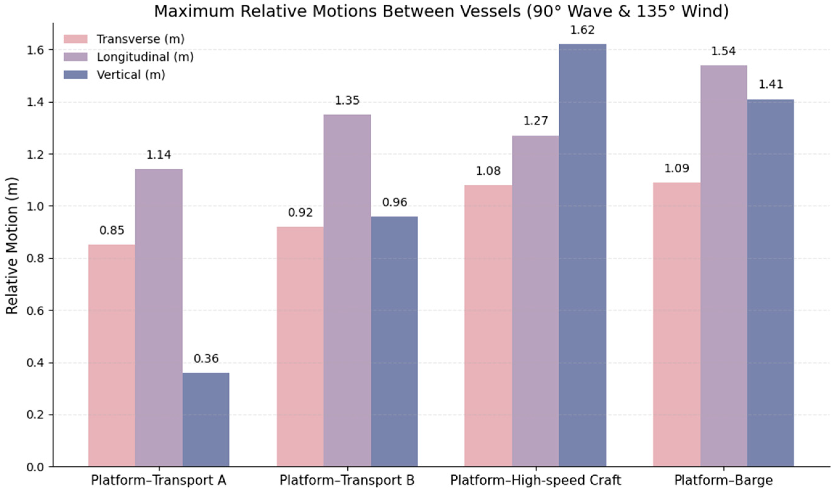
Relative motions between the transfer platform and the companion vessels are of primary importance for assessing cargo transfer operability and collision risk. Maximum relative displacements in the lateral (Transverse), longitudinal, and vertical directions are summarized in Figure 25, Figure 26, Figure 27, Figure 28 and Figure 29.
Figure 25.
Maximum relative motions between vessels under 0° wave and 0° wind conditions.
Figure 26.
Maximum relative motions between vessels under 90° wave and 90° wind conditions.
Figure 27.
Maximum relative motions between vessels under 45° wave and 45° wind conditions.
Figure 28.
Maximum relative motions between vessels under 135° wave and 90° wind conditions.
Figure 29.
Maximum relative motions between vessels under 90° wave and 135° wind conditions.
3.2.1. Transfer Platform and Transport Vessel A
For the transfer platform and transport vessel A pair, the maximum lateral relative displacement is 1.64 m, occurring under 135° waves + 90° wind (Figure 28). The largest longitudinal relative motion reaches 1.29 m under 0° waves + 0° wind (Figure 25). Vertical relative motion attains a maximum value of 0.85 m, which is observed under both 0° waves + 0° wind (Figure 25) and 45° waves + 45° wind (Figure 27).
Overall, the relative motions for this pair remain moderate, with vertical displacements generally smaller than those observed for lighter vessels.
3.2.2. Transfer Platform and Transport Vessel B
For the platform and transport vessel B pair, the largest lateral relative displacement is 1.51 m, occurring under 0° waves + 0° wind (Figure 25). The maximum longitudinal relative motion reaches 2.24 m, also under 0° waves + 0° wind, representing the largest longitudinal relative displacement among all vessel pairs considered.
The maximum vertical relative displacement for this pair is 1.48 m, occurring under 45° waves + 45° wind (Figure 27). Compared with other pairs, this combination of head seas and oblique seas results in relatively large longitudinal and vertical relative motions.
3.2.3. Transfer Platform and High-Speed Craft
The platform–high-speed craft pair exhibits some of the largest relative motions among all vessel combinations. The maximum lateral relative displacement reaches 1.80 m under 90° waves + 90° wind (Figure 26). The largest longitudinal relative motion is 2.05 m, occurring under 0° waves + 0° wind (Figure 25).
Vertical relative motion is most pronounced for this pair, with a maximum value of 1.62 m observed under 90° waves + 135° wind (Figure 29). These results indicate a strong sensitivity of the relative motion response to both beam and oblique wave–wind conditions.
3.2.4. Transfer Platform and Barge
For the platform–barge pair, the maximum lateral relative displacement is 1.65 m, occurring under 90° waves + 90° wind (Figure 26). The largest longitudinal relative motion reaches 1.98 m under 0° waves + 0° wind (Figure 25).
The maximum vertical relative displacement for this pair is 1.67 m, observed under 135° waves + 90° wind (Figure 28), which is the largest vertical relative motion among all vessel pairs considered.
3.2.5. Overall Characteristics of Relative Motions
Across all vessel pairs, the most demanding relative horizontal motions tend to occur under beam or oblique wave conditions (90–135°), particularly when combined with cross winds. In contrast, maximum vertical relative motions are observed either under oblique wave conditions (45°) or stern-quartering seas (135°), depending on the vessel pair.
Compared with absolute motions, the amplitude of relative motion is smaller, but it is more sensitive to phase differences between neighboring units, highlighting their importance for transfer safety assessment.
4. Discussion
4.1. Shielding Effect
The results presented in Section 3 show that there are significant differences in the motion responses of the five floating bodies. Under most environmental conditions, the transfer platform and Transport Vessel A exhibit smaller horizontal and rotational motions, whereas the high-speed craft and the barge show much larger responses. This contrast is particularly evident under the 135° wave and 90° wind condition, where the sway motions of the barge and the high-speed craft reach 10.23 m and 9.86 m, respectively, while the transfer platform shows a markedly smaller value of 3.86 m. Similar differences are also observed in surge and yaw responses. These systematic response differences indicate that the motion distribution within the system is strongly position-dependent rather than uniform.
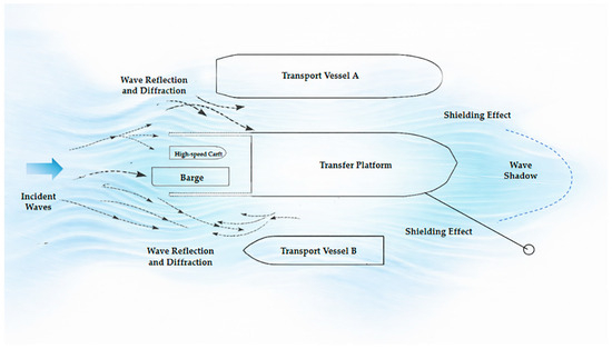
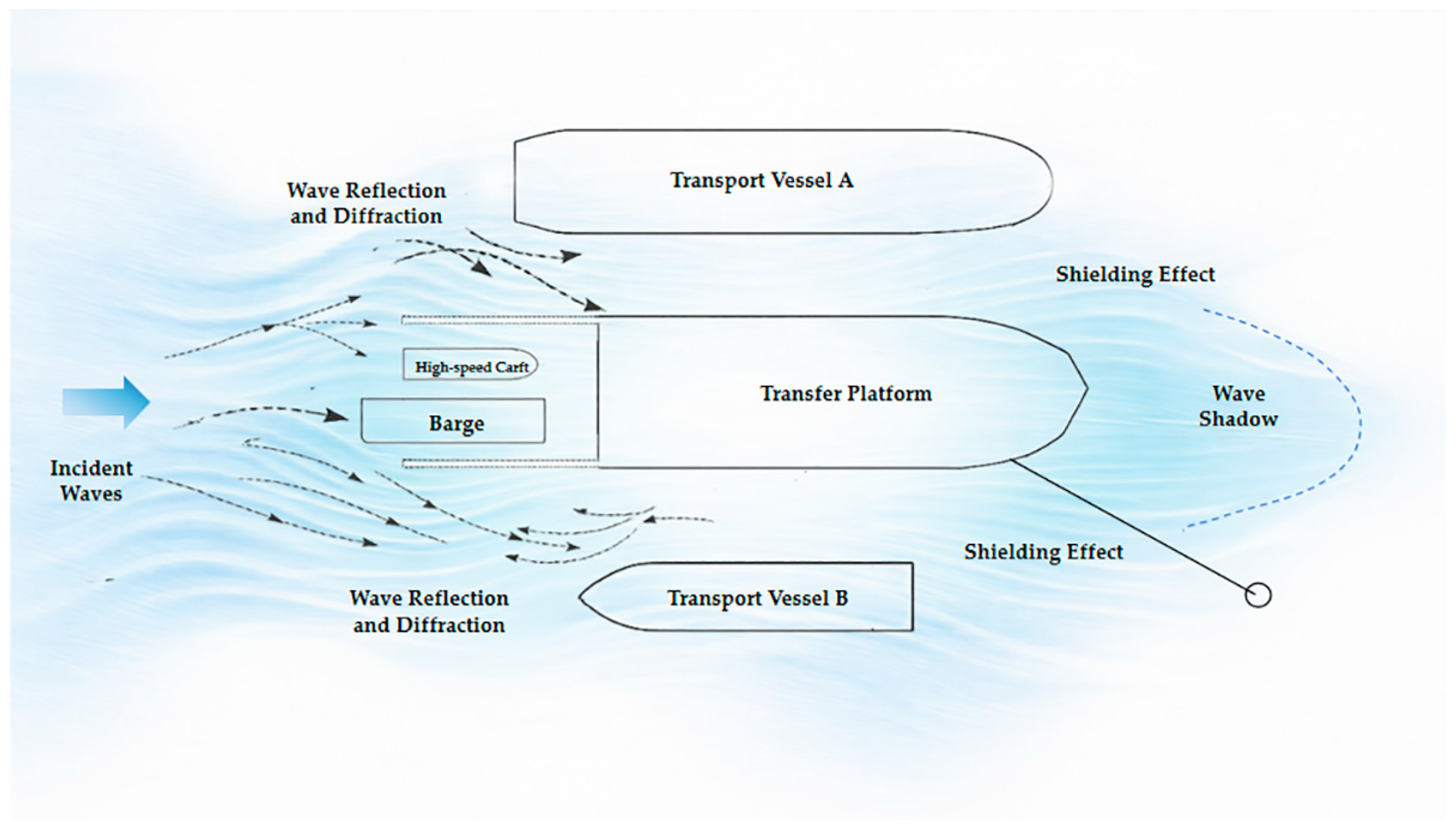
This behavior can be interpreted as a shielding effect within the multi-body arrangement, as is shown in Figure 30. The large floating body near the center of the system intercepts the incident wave energy, thus reducing the impact on the floating body at the leeward sides. The outer vessels facing the waves, however, may also be influenced by reflected and diffracted wave components generated by the central body, thus enduring stronger wave loads. As a result, the outer vessels tend to exhibit amplified motions, especially in horizontal directions.
Figure 30.
Schematic diagram of the shielding effect in the multi-body floating system.
The present observations provide experimental support for the statement that the system response cannot be interpreted as a simple superposition of isolated-body motions. If the motions of each unit were governed only by direct far-field loading, the response differences among the units under the same environmental condition would be expected to be much smaller. Instead, the measured results show that system position, neighbor arrangement, and hydrodynamic interaction jointly govern the response pattern. This finding is consistent with previous studies showing that diffraction–radiation interactions and narrow-gap effects can redistribute hydrodynamic loads and modify body motions in closely spaced multi-body systems, as reported by Newman [2], Hong et al. [3].
4.2. Gap Amplification
In addition to the global shielding effect, the test data also show that the relative motion between adjacent floating bodies is significantly amplified. As shown in Section 3.2, the largest transverse relative motions are mainly observed under beam and oblique wave conditions, while large vertical relative motions occur in several 45°, 90°, and 135° cases. The platform–high-speed craft and platform–barge pairs are particularly sensitive, with peak transverse relative motions of 1.80 m and 1.65 m under 90° wave and 90° wind, and vertical relative motions of up to 1.67 m for the platform–barge pair under 135° wave and 90° wind.
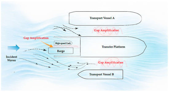
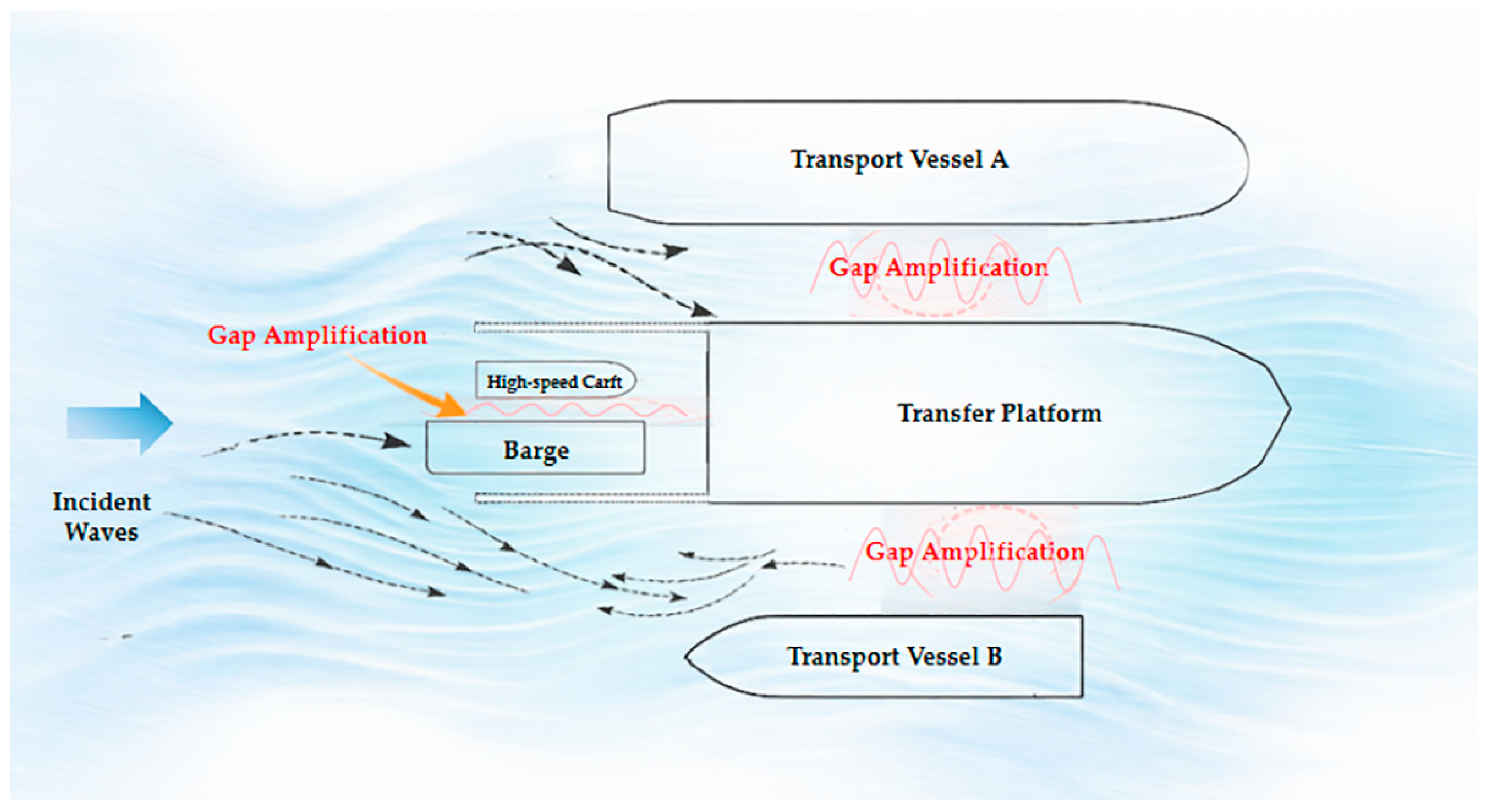
These results suggest that local hydrodynamic interaction within narrow or semi-confined gaps plays an important role in amplifying pairwise relative response. When waves propagate into the space between adjacent bodies, part of the wave energy may be trapped and repeatedly reflected, intensifying oscillatory flow within the gap, as is shown in Figure 31. Under favorable incident directions, the longitudinal and transverse components of wave excitation act simultaneously on the confined water body, which may enhance local free-surface oscillation and thus increase relative motion between neighboring vessels.
Figure 31.
Schematic diagram of gap amplification in the narrow gaps between floating bodies.
It should be noted that the present experiments do not directly measure the free-surface elevation inside the gaps; therefore, the term gap amplification is used here in an interpretation based on the measured relative-motion pattern rather than as a direct proof of resonance frequency identification. Nevertheless, the fact that relative motions are consistently enlarged under beam and oblique conditions, together with the greater sensitivity of lighter peripheral units, supports the existence of strong gap-related interaction effects. This interpretation is also in qualitative agreement with previous experimental and numerical studies on narrow-gap hydrodynamics in multi-body systems, particularly the experimental work of Chen et al. [17] and the numerical study of Jiang et al. [7].
4.3. Influence of Mooring Asymmetry on Global Motions
Another important feature observed in the tests is the strong influence of mooring asymmetry on the global horizontal response of the system. The most severe combined drift-type response occurs under the 135° wave and 90° wind condition, where the peripheral units exhibit simultaneously large sway, surge, and yaw motions.
This behavior is closely related to the asymmetric restoring characteristics of the mooring arrangement. The system is centered on a single-point mooring transfer platform, so the restoring stiffness is not distributed uniformly over all floating bodies. When the incident environmental loads are aligned unfavorably with the principal restoring direction of the mooring system, the restoring forces become unevenly shared among the connected bodies. Units located farther from the mooring reference point are then less effectively restrained and become more susceptible to coupled drift and yaw motions.
The experimental results therefore suggest that the observed global response is governed by the combined action of environmental directionality and nonuniform restoring stiffness. This mechanism helps explain why oblique loading cases produce larger horizontal excursions than some head-sea cases, even though the latter may appear simpler from the perspective of wave incidence alone. It also indicates that, in engineering assessment, the global dynamic behavior of a multi-body offshore operation system should not be evaluated solely from incident wave direction, but also from the spatial relation between load direction and mooring restoring layout.
4.4. Engineering Implications
From an engineering perspective, the results highlight three coupled design concerns in offshore replenishment operations: shielding effect, gap effect, and mooring asymmetry. These effects should be considered simultaneously rather than independently.
First, the amplified motions of peripheral units indicate that outer vessels may govern the operational limit of the entire system, even when the centrally moored platform remains relatively stable. Second, the increase in transverse and vertical relative motions implies a higher risk of excessive fender compression, repeated impact, and local collision during close-proximity operations. Third, large horizontal drift and yaw under oblique environmental loading may cause unfavorable redistribution of mooring forces and reduce positional control of the system.
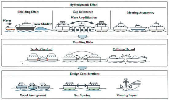
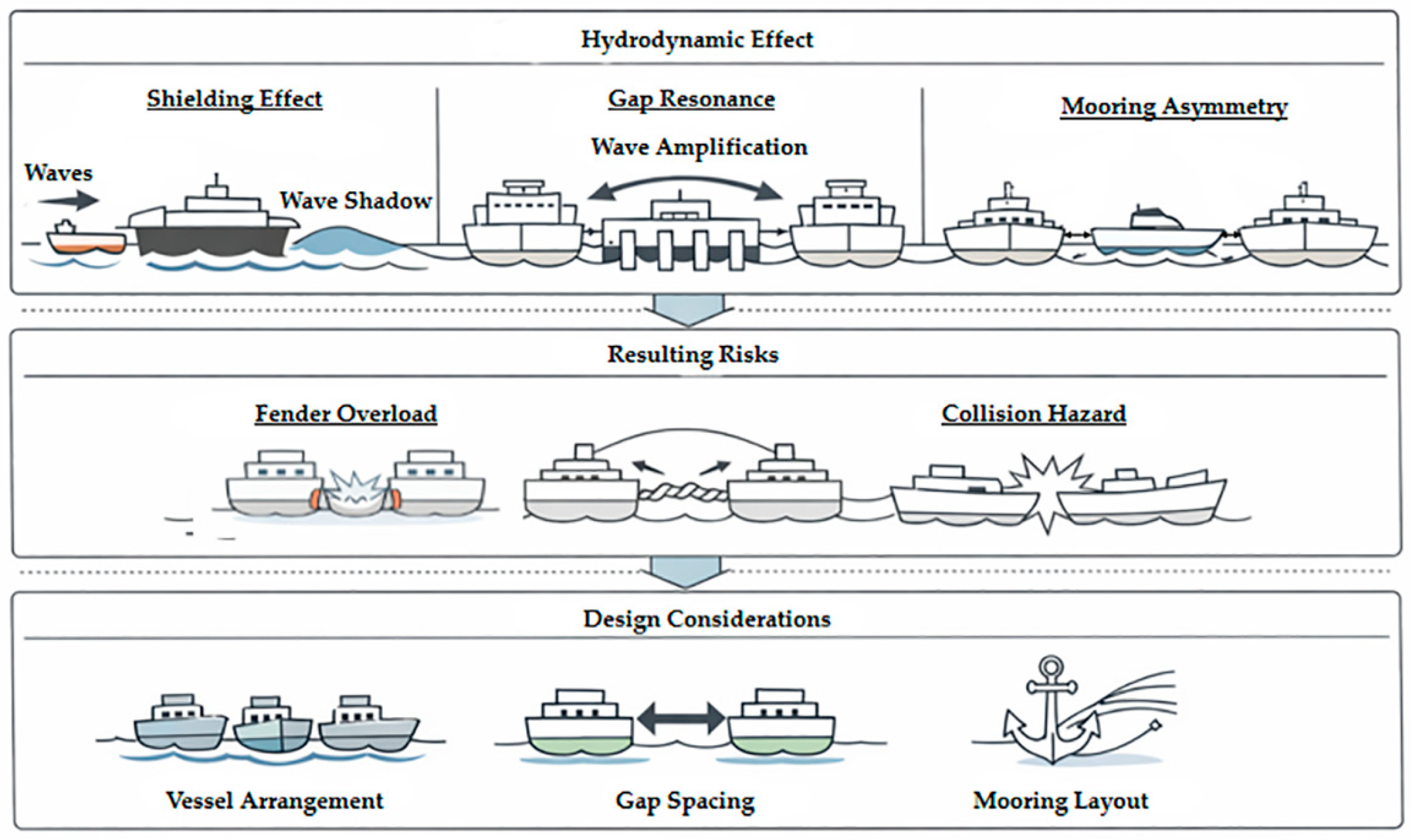
Therefore, as shown in Figure 32, the layout of vessels, the spacing between adjacent units, and the distribution of restoring stiffness should be jointly optimized in the planning and design stage. Particular attention should be paid to oblique wind–wave conditions, which tend to produce the most unfavorable responses in the present system.
Figure 32.
Schematic illustration of hydrodynamic effects, associated risks, and engineering considerations in a multi-body floating system.
5. Conclusions
Based on the physical model test of the five-body floating system under the combined action of wind, wave and current loading, the main conclusions are as follows.
- There are significant hydrodynamic interactions in the multi-body floating system, and its overall dynamic response cannot be approximated by the superposition of independent motions of each floating body. The range of motion among the five bodies is quite different, which indicates that the overall system behavior should be assessed at the system level rather than by considering each unit independently.
- A pronounced shielding effect was identified in the experiments. The translation and rotation amplitudes of the large floating body located in the center of the system were small. In contrast, the responses of outer vessels, including high-speed craft and barge, were significantly amplified. This result indicates that wave energy was redistributed within the multi-body arrangement.
- Relative motions between adjacent bodies increased markedly under beam and oblique wave conditions. Large transverse and vertical relative displacements were observed for several vessel pairs, suggesting strong gap-related hydrodynamic interaction effects. These impacts are critical for assessing the safety of close operations.
- The asymmetry of the mooring system has a significant impact on the overall response, especially under oblique environmental loads. When the incident directions of wind and waves are not aligned, the distribution of mooring restoring force is unbalanced, making the units farther from the mooring reference point more susceptible to large drift and yaw motions.
- From an engineering perspective, shielding effect, gap amplification effect and mooring stiffness distribution must be considered simultaneously. The experimental data presented in this paper provide a useful reference for verifying the numerical tools and guiding the layout and mooring design of multi-body floating systems in complex marine environments.
Author Contributions
The manuscript was written by L.S.; all authors discussed the original idea; conceptualization, L.S. and H.T.; methodology, L.S.; formal analysis, L.S. and R.G.; investigation, J.M.; resources, J.Y.; data curation, J.M.; writing—original draft preparation, L.S.; writing—review and editing, L.S., J.Y., H.T. and Z.J.; visualization, R.G.; supervision, J.Y.; project administration, J.Y.; funding acquisition, J.Y. All authors have read and agreed to the published version of the manuscript.
Funding
This work was supported by the National Natural Science Foundation of China (52471299), the Tianjin Science and Technology Plan Major Project (24ZXZSSS00410), and the Tianjin Renai College-Tianjin University Teacher Development Fund Cooperation Project (FZ231007).
Data Availability Statement
Data are contained within the article.
Acknowledgments
During the preparation of this manuscript, the authors used AI-assisted language editing tools for the purposes of grammar correction. The authors have reviewed and edited the output and take full responsibility for the content of this publication.
Conflicts of Interest
The authors declare that this study received funding from the Tianjin Renai College-Tianjin University Teacher Development Fund Cooperation Project (FZ231007). The funder was not involved in the study design, collection, analysis, interpretation of data, the writing of this article or the decision to submit it for publication.
References
- Ohkusu, M. Hydrodynamic Forces on Multiple Cylinders in Waves; A research report; Research Institute for Applied Mechanics, Kyushu University: Fukuoka, Japan, 1969; Volume 18, pp. 127–142. [Google Scholar]
- Newman, J.N. Wave Effects on Multiple Bodies; MIT Report; Massachusetts Institute of Technology: Cambridge, MA, USA, 2001. [Google Scholar]
- Hong, S.Y.; Kim, J.H.; Cho, S.K.; Choi, Y.; Kim, Y. Numerical and experimental study on hydrodynamic interaction of side-by-side moored multiple vessels. Ocean Eng. 2004, 32, 783–801. [Google Scholar] [CrossRef] [Scilit]
- Feng, X.; Bai, W. Hydrodynamic analysis of marine multi-body systems by a substructure coupling model. Appl. Ocean Res. 2017, 64, 217–229. [Google Scholar]
- Fan, T.; Fang, J.; Yan, X.; Ma, Y. Numerical study of an innovative concept for a multi-body anti-pitching semi-submersible floating offshore wind turbine. J. Mar. Sci. Eng. 2024, 12, 553. [Google Scholar] [CrossRef] [Scilit]
- Konispoliatis, D.N.; Manolas, D.I.; Voutsinas, S.G.; Mavrakos, S.A. Coupled dynamic response of an offshore multi-purpose floating structure. Front. Energy Res. 2022, 10, 920151. [Google Scholar] [CrossRef] [Scilit]
- Jiang, Z.; Li, F.; Tavakoli, S.; Kujala, P.; Suominen, M.; Hirdaris, S. A viscous investigation on the hydrodynamic coefficients and wave loads under the interaction of side-by-side cylinders in regular waves. Ocean Eng. 2024, 297, 117156. [Google Scholar] [CrossRef] [Scilit]
- Chen, M.; Deng, J.; Yang, Y.; Zhou, H.; Tao, T.; Liu, S.; Sun, L.; Hua, L. Performance analysis of a floating wind–wave power platform. J. Mar. Sci. Eng. 2024, 12, 206. [Google Scholar] [CrossRef] [Scilit]
- Lamei, A.; Hayatdavoodi, M.; Riggs, H.R.; Ertekin, R.C. Dynamic response of multi-unit floating offshore wind turbines to wave, current, and wind loads. J. Renew. Sustain. Energy 2024, 16, 013307. [Google Scholar] [CrossRef] [Scilit]
- Wu, F.; Zhang, K.; Cheng, X.; Wang, J.; Xie, C.; Yu, J.; Gu, Y. Analysis of hydrodynamic performance and mooring dynamic response of offshore dual-module floating photovoltaic platform. In Proceedings of the ASME 2024 43rd International Conference on Ocean, Offshore and Arctic Engineering, Singapore, 9–14 June 2024; Volume 1, p. OMAE2024-125502. [Google Scholar] [CrossRef] [Scilit]
- Jifaturrohman, M.I.; Utama, I.K.A.P.; Putranto, T.; Setyawan, D.; Huang, L. A study into the effect of hull configuration on the performance of floating solar PV structure. J. Adv. Res. Fluid Mech. Therm. Sci. 2024, 124, 124–141. [Google Scholar] [CrossRef] [Scilit]
- Jifaturrohman, M.I.; Utama, I.K.A.P.; Putranto, T.; Setyawan, D.; Suastika, I.K.; Sujiatanti, S.H.; Satrio, D.; Hayati, N.; Huang, L. Hydrodynamic modeling of unstretched length variations in nonlinear catenary mooring systems for floating PV installations in small Indonesian islands. Modelling 2025, 6, 31. [Google Scholar] [CrossRef] [Scilit]
- Shi, J.; Hu, M.; Zhang, Y.; Chen, X.; Yang, S.; Hallak, T.S.; Chen, M. Dynamic analysis of crane vessel and floating wind turbine during temporary berthing for offshore on-site maintenance operations. J. Mar. Sci. Eng. 2024, 12, 1393. [Google Scholar] [CrossRef] [Scilit]
- Meduri, A.; Kang, H. Synergistic integration of multiple wave energy converters with adaptive resonance and offshore floating wind turbines through Bayesian optimization. J. Mar. Sci. Eng. 2024, 12, 1455. [Google Scholar] [CrossRef] [Scilit]
- Men, X.; He, J.; Jiao, B.; Zhu, G.; Lin, H.; Sun, H. Time-domain simulation of coupled motions for five fishing vessels moored side-by-side in a harbor. J. Mar. Sci. Eng. 2025, 13, 307. [Google Scholar] [CrossRef] [Scilit]
- Zhao, Y.; Xie, S.; Ma, C. Experimental investigations on the hydrodynamics of a multi-body floating aquaculture platform exposed to sloping seabed environment. Front. Mar. Sci. 2022, 9, 1049769. [Google Scholar] [CrossRef] [Scilit]
- Chen, M.; Guo, H.; Wang, R.; Tao, R.; Cheng, N. Effects of gap resonance on the hydrodynamics and dynamics of a multi-module floating system with narrow gaps. J. Mar. Sci. Eng. 2021, 9, 1256. [Google Scholar] [CrossRef] [Scilit]
- Mohapatra, S.C.; Amouzadrad, P.; Bispo, I.B.d.S.; Soares, C.G. Hydrodynamic response to current and wind on a large floating interconnected structure. J. Mar. Sci. Eng. 2025, 13, 63. [Google Scholar] [CrossRef] [Scilit]
- JTJ/T234-2001; Wave Model Test Code. Ministry of Transport of the People’s Republic of China: Beijing, China, 2001.
- JTS 165-2013; General Code for Design of Sea Ports. Ministry of Transport of the People’s Republic of China: Beijing, China, 2013.
- JTS 144-1-2010; Code for Loads of Port Engineering. Ministry of Transport of the People’s Republic of China: Beijing, China, 2010.
- Oil Companies International Marine Forum (OCIMF). Mooring Equipment Guidelines, 3rd ed.; OCIMF: London, UK, 2008. [Google Scholar]
- British Standards Institution (BSI). Maritime Works—General Code of Practice for Planning and Design for Operations; BSI: London, UK, 2013. [Google Scholar]
- PIANC. Criteria for Movements of Moored Ships in Harbors: A Practical Guide; PIANC: Brussels, Belgium, 1995. [Google Scholar]

Disclaimer/Publisher’s Note: The statements, opinions and data contained in all publications are solely those of the individual author(s) and contributor(s) and not of MDPI and/or the editor(s). MDPI and/or the editor(s) disclaim responsibility for any injury to people or property resulting from any ideas, methods, instructions or products referred to in the content. |
© 2026 by the authors. Licensee MDPI, Basel, Switzerland. This article is an open access article distributed under the terms and conditions of the Creative Commons Attribution (CC BY) license.