


Abstract
Unlike traditional marine floating platforms, floating offshore wind turbines (FOWTs) are subjected to larger overturning moments. This study presents a novel floating offshore wind turbine concept—termed the Multi-Body Anti-Pitching Floating Wind Turbine (MAFWT)—designed to mitigate excessive pitching motion of semi-submersible FOWTs. The MAFWT integrates three Wave-star-like appendages arranged in the UMaine VolturnUS-S platform. A fully coupled dynamic model is developed within the FAST-to-AQWA (F2A) simulation framework. Parametric time- and frequency-domain analyses are subsequently conducted under both regular wave/steady wind and irregular wave/turbulent wind conditions to investigate the influence of stiffness parameter K and damping parameter B on system dynamics. Results demonstrate that increasing stiffness enhances the restoring moment, thereby reducing the static pitching offset and overall dynamic response (with the maximum and average values decreasing by 27.6% and 31.9%, respectively). However, it may amplify low-frequency slow-drift motions (with the maximum and average values of surge increasing by 9.4% and 9.5%, respectively). In contrast, damping primarily dissipates kinetic energy, yielding up to a 25.5% reduction in pitch angular velocity and significantly mitigating power output fluctuations (the standard deviation decreased by 16.4%). Furthermore, increases in the stiffness coefficient and damping coefficient result in respective slight increments of 0.12% and 0.18% in the average power output. This work elucidates the distinct physical mechanisms through which stiffness and damping govern pitch suppression.
1. Introduction
Offshore wind power is one of the most important renewable energy resources. The development of fixed offshore wind power generation in deep water poses a great challenge in terms of safety and economy [1]. Currently, almost all offshore wind turbines are using fix-bottom foundations, mostly monopiles, in shallow waters. While when the water depth exceeds 60 m, floating offshore wind turbines (FOWTs) are considered more economical than fixed-bottom ones [2]. Offshore wind turbines with floating substructures experience complex dynamics compared with those on bottom-fixed foundations. The motion of the floating platform is due to the simultaneous effect of waves and current, hydrostatic and mooring restoring forces, and loads due to the aerodynamic load on the rotor and the tower of the wind turbine [3]. It is well established that the hydrodynamic performance of submerged structures is highly sensitive to their geometric configuration and submergence depth. For instance, the power coefficient of tidal turbines is critically dependent on the immersion depth [4]. Unlike traditional offshore oil and gas platforms, FOWTs exhibit more pronounced pitch motion responses due to the substantial aerodynamic loads generated by the rotor. Water tank model tests on semi-submersible floating wind turbines have demonstrated that the maximum pitch angle can reach up to 10° under operational conditions [5]. Such increased pitch motion intensifies dynamic oscillations at the tower top and blade tips, leading to significantly higher bending moments and shear forces at critical structural locations, including the tower base and blade roots [6]. These load amplifications adversely affect the structural fatigue life of floating wind systems. Studies indicate that a 15% reduction in pitch motion amplitude can extend the safe service life of the turbine by over two-fold [7]. Therefore, mitigating pitch motion response is crucial for enhancing the long-term reliability and operational safety of FOWTs.
Meanwhile, the pitch-restoring moment of a floating body is governed by the center of gravity (COG), the center of buoyancy (COB), and the moment of inertia of the waterplane area. However, in the case of FOWTs, lowering the COG and raising the COB is challenging due to the presence of the tall wind turbine structure, thereby limiting the enhancement of the restoring moment. Consequently, for the pitch and roll motions of semi-submersible platforms, increasing the moment of inertia of the waterplane area is widely regarded as the most effective approach to achieving favorable dynamic stability [8].
Based on the aforementioned analysis, this study proposes a Multi-body Anti-Pitching Floating Wind Turbine (MAFWT) concept, which comprises the UMaine VolturnUS-S semi-submersible platform and three pendulum-type floaters with a Wave-Star configuration [9]. Each oscillating-arm appendage consists of two parts: the upper part of the float is cylindrical, while the lower part is hemispherical, with the waterline located at their junction. The three anti-pitching appendages are arranged in a circular array with an inter-appendage angle of 120°. More specifically, the UMaine VolturnUS-S model is adopted as it represents a well-documented and representative semi-submersible FOWT design. Meanwhile, the coupling between the prototype Wave-Star floaters and the 5 MW FOWT has been thoroughly investigated [10]. Thus, its dimensions are redesigned in this study and designated as the Big Wave-Star (BWS). In this study, we propose a concept for an anti-pitching floating wind turbine, which comprises a 15-megawatt (MW) semi-submersible Floating Offshore Wind Turbine (FOWT) and three BWSs (Big Wave-Star WECs). More specifically, the UMaine VolturnUS-S model is employed, as it represents a representative and well-documented semi-submersible FOWT design. Concurrently, the three BWSs are respectively mounted on the three offset columns of the semi-submersible platform.
The MAFWT system proposed in this study shares a comparable configuration with conventional floating wind-wave hybrid power generation systems. Its specific design draws upon and advances multiple key technological developments achieved in recent years. Yang et al. constructed a fully coupled model of a 15 MW offshore wind turbine and flapping-wing motion-reducing appendages using F2A, and explored the influence of the multi-body motion-reducing device on the platform under the combined action of regular waves and turbulent wind [11]. Wei et al. proposed a scheme combining a floating semi-submersible platform with a concentric rocker arm appendage array, and conducted model tests to study the effect of the appendage array on platform motion [12]. Cheng et al. investigated the coupling effect between heave buoys and a Spar platform with a vertical-axis wind turbine, and analyzed the motion suppression effect of annular buoys on the platform [13]; Kamarloei et al. experimentally confirmed that the interaction between buoys and the platform can effectively reduce the heave and roll motions of the platform, and the degree of reduction is closely related to the PTO damping characteristics [14]. Luan et al. used a combination of numerical simulation and experiments to compare and analyze the motion responses and energy capture characteristics of the STC (Spar–Torus Combination) single-buoy system and the SFC three-pendulum buoy system [15]. Li et al. studied an integrated energy platform integrating heave buoys, horizontal-axis turbines, and wind turbines, and found that the addition of wave energy and tidal current energy devices can reduce the platform’s heave and pitch motions by 22–45% while significantly improving the total power generation efficiency of the system [16]; Gaspar et al. and Kamarlouei et al. studied the FOWT, connecting a concentric array of WECs, by using experimental methods [17,18]. Other researchers have followed this idea by combining the Wave-star WEC with the FOWTs [18,19,20,21].
Concurrently, studies focusing on the optimization of damping and stiffness parameters for enhancing the energy capture efficiency of wave energy converters (WECs) also offer relevant reference insights. Wang et al. established a numerical model of a hybrid energy system combining a floating offshore wind turbine (FOWT) and a wave energy converter (WEC) based on the coupled framework of OpenFAST and WEC-sim (OWS), and developed a multi-objective, multi-parameter configuration optimization solver to find the optimal power take-off (PTO) damping [22]. Borg et al. innovatively proposed using heave buoys as motion dampers for floating wind turbines, and achieved a balance between minimizing heave motion amplitude and maximizing energy capture by optimizing damping and stiffness coefficients, but the study did not involve motions in other degrees of freedom [23].
Although existing literature has made significant progress in optimizing floating wind-wave hybrid systems, most studies focus primarily on power output metrics or control strategies, often overlooking the underlying physical mechanisms governing structural parameters. Typically, stiffness and damping are treated as coupled variables, or optimization efforts are restricted to damping alone. This study aims to bridge this gap by conducting a rigorous decoupling analysis of stiffness and damping effects specifically for Multi-Body Anti-pPitching Floating Wind Turbines (MAFWTs). This paper is divided into five parts. Section 2 provides a detailed introduction to the adopted coupled numerical model, including the hydrodynamic model based on the three-dimensional frequency-domain potential flow theory, the aerodynamic model based on the blade element momentum theory, and the time-domain fully coupled model implemented through the F2A framework. Section 3 validates the reliability of the basic numerical model through static water stiffness and free decay tests. Then, this section conducts parametric studies and comparative discussions on the system under different stiffness and damping coefficient configurations, covering time-domain and frequency-domain responses under various conditions such as free decay, regular waves, and irregular waves. Section 4 summarizes the key conclusions of stiffness and damping.
2. Numerical Model
2.1. Hydrodynamic Model
The FOWT based on multi-body Anti-Pitching appendages proposed in this study is a multi-float system comprising a floating platform and anti-pitching floaters. The interactions between the multi-float structures exert a significant influence on the overall performance of FOWTs. In accordance with the three-dimensional linear frequency-domain potential flow theory, assuming the fluid is ideal and incompressible with irrotational flow, the velocity potential of the fluid can be expressed as [24]:
In the equation, denotes the incident wave velocity potential, denotes the diffraction velocity potential, and denotes the radiation velocity potential.
In a marine environment with water depth , the incident wave velocity potential can be written as:
In the formula, denotes wave number, denotes angular frequency, denotes the incident wave amplitude, and denotes the wave direction angle.
If the displacement of the -th motion mode of the -th floating body is denoted as (where , corresponding to surge, sway, heave, roll, pitch, and yaw, respectively), and is the corresponding motion amplitude, then the radiation velocity potential can be expressed as:
In the formula, denotes the radiation unit velocity potential corresponding to the -th mode motion of the -th floating body, and it satisfies the following boundary conditions:
In the equation, denotes the partial derivative along the inward normal direction of the floating body surface, and denotes the wetted surface of the -th floating body. By analogy, the boundary condition satisfied by the diffraction velocity potential can be derived by modifying the body surface condition to .
2.2. Aerodynamic Model
The Blade Element Momentum (BEM) theory is employed in the calculation of torque and thrust for wind turbine blades. This theory assumes that the blade is partitioned into a series of independent blade elements along the spanwise direction. The lift and drag forces exerted on each blade element are computed based on incoming flow conditions and momentum theory, following which the aerodynamic loads on the blade elements are integrated spanwise to derive the overall forces and moments acting on the entire blade. The rotor thrust, , and torque, , can be expressed as
In the equation, denotes the relative inflow wind speed; is the number of blade elements; and and denote the lift and drag coefficients of the blade element airfoil, respectively. is the inflow angle, and is the radius of the blade. Aerodynamic coefficients under unsteady conditions are corrected using the Beddoes-Leishman dynamic stall model. Subsequently, the total thrust and total torque of the entire rotor are derived by integrating the forces acting on each blade element [25].
2.3. Coupled Model
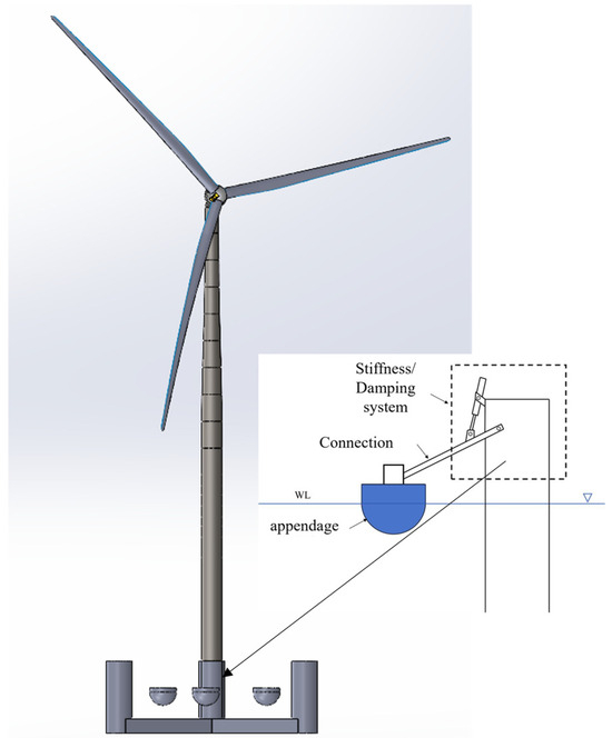
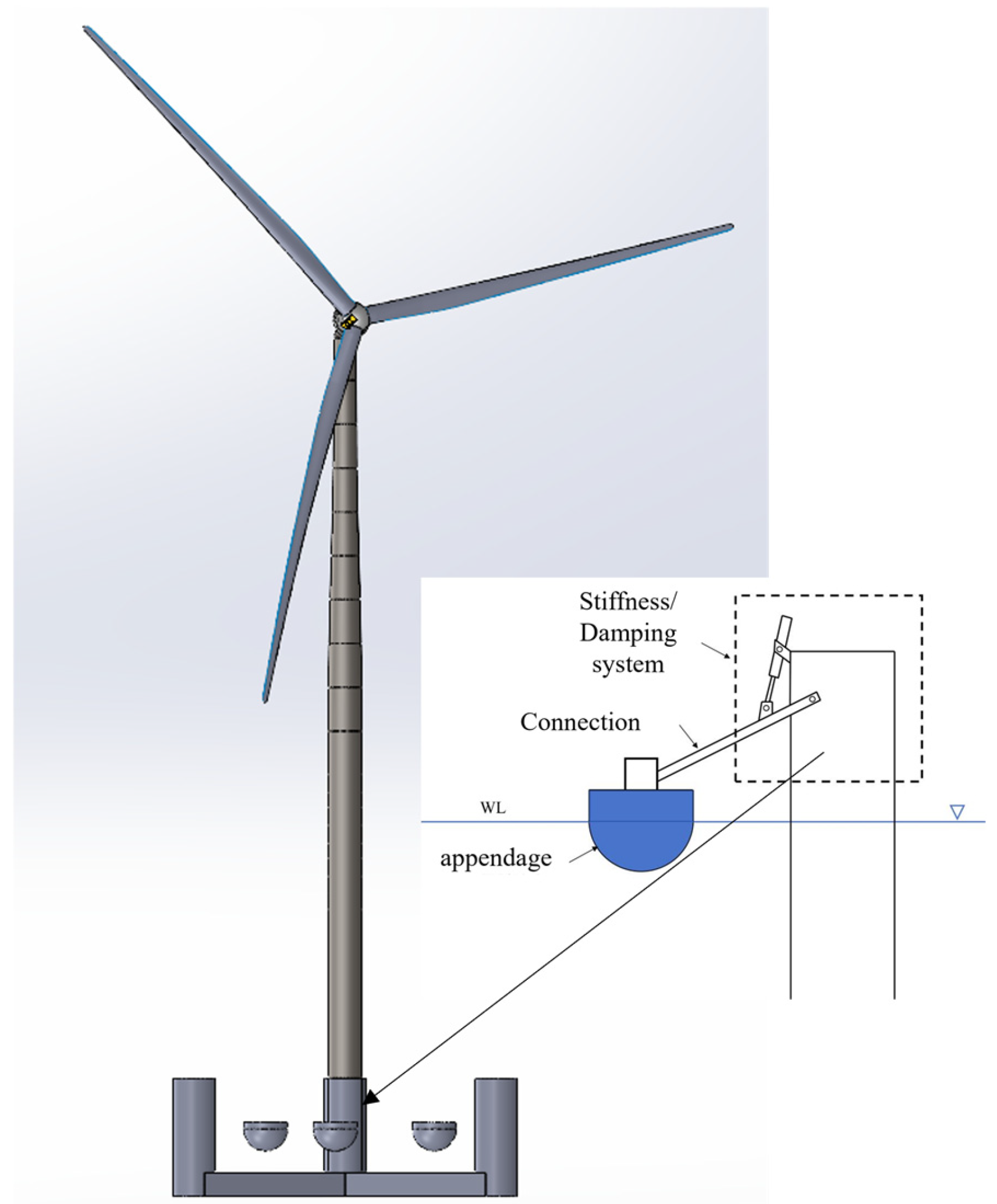
The motion responses of the floating platform integrated with the BWSs were calculated using the built-in time-domain solver of the hydrodynamic simulation software AQWA (version 2025 R1). The accuracy of its calculation results has been verified by extensive comparisons with theoretical analyses and model tests, indicating high simulation reliability. Considering the balance between calculation accuracy and computational cost, a grid size of 1 m was adopted for the platform and multi-body Anti-Pitching appendages in this study. To facilitate the calculation of the coupled dynamic response of the novel FOWT, the multi-body Anti-Pitching appendages were simplified as a spring-damper system, with the connecting rod arms assumed to be massless. In AQWA, the “Joint” connection type was employed to link the floating foundation and the wave-energy floats; the stiffness and damping coefficients of the Joint correspond to the connection parameters K and B between the appendages and the platform, respectively. The schematic diagram and specific parameters are presented in Figure 1, Table 1 and Table 2.
Figure 1.
Schematic diagram of the floating platform and anti-pitching appendages.
Table 1.
Design Parameters of UMaine VolturnUS-S Semi-submersible Foundation.
Table 2.
The main design parameters of the multi-body anti-pitching appendages used in this article.
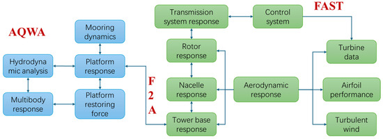
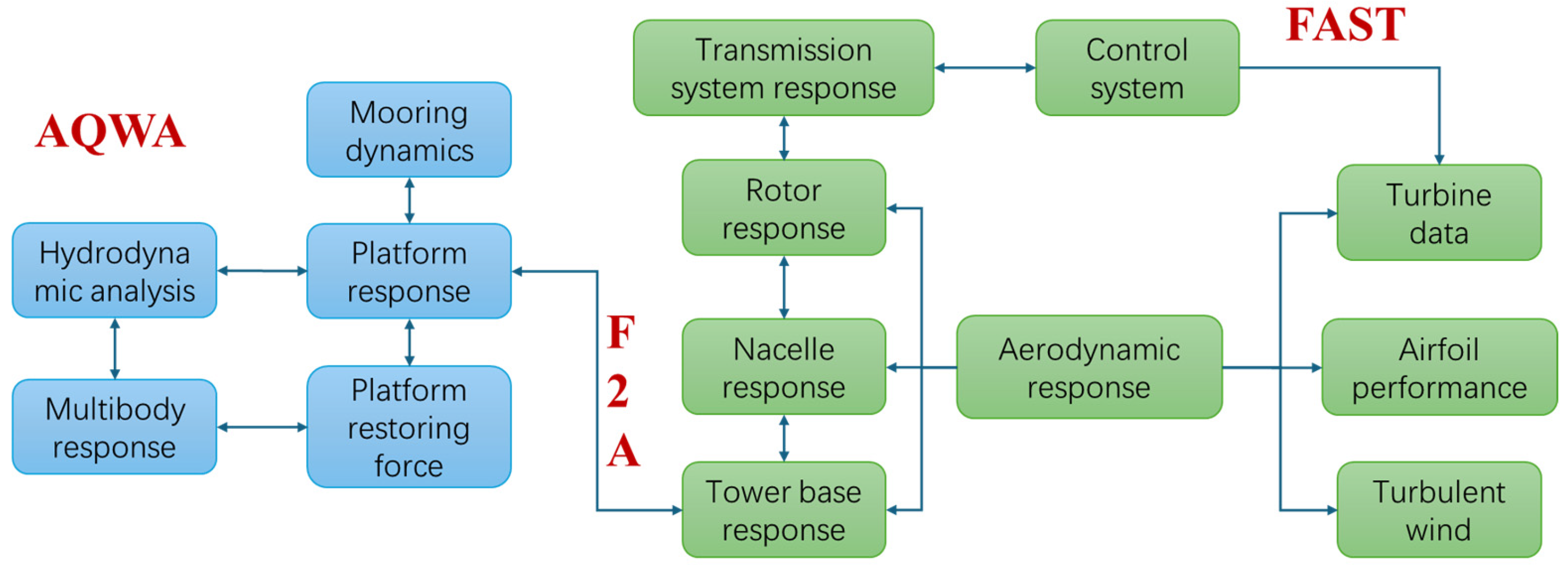
The model was constructed using the F2A (FAST-to-AQWA) fully coupled numerical simulation framework proposed by Yang et al. [26]. The analysis workflow of the F2A model is illustrated in Figure 2 and the design parameters of the IEA 15 MW wind turbine adopted in this study are presented in Table 3. This model enables bidirectional real-time data interaction between OpenFAST (version 2025) and AQWA via dynamic link libraries (DLLs): OpenFAST is responsible for calculating the wind turbine’s aerodynamic loads, structural dynamics, and control system responses, and transmits the six-degree-of-freedom (6-DOF) loads at the tower base to AQWA. AQWA solves the platform’s hydrodynamic responses based on three-dimensional potential flow theory, incorporating environmental loads such as waves and currents, and feeds back the platform’s motion states to OpenFAST in real time—thereby accurately capturing the coupling effects among aerodynamics, hydrodynamics, servo control, and structural elasticity. This coupling method has been widely applied in FOWT research and adopted by numerous scholars, exhibiting reliable accuracy and engineering applicability [20,27,28].
Figure 2.
Flowchart of the fully coupled numerical model analysis.
Table 3.
Design parameters of IEA 15 MW wind turbine.
3. Results
3.1. Model Verification
3.1.1. Static Water Stiffness
To validate the accuracy of the hydrodynamic model for the floating platform developed in this study, its hydrostatic stiffness coefficients, natural periods of surge, heave, and pitch motions, as well as the Response Amplitude Operators (RAOs) for each degree of freedom, were compared against the benchmark results provided by the National Renewable Energy Laboratory (NREL) [9]. As shown in Table 4, the hydrostatic stiffness coefficient for heave () of the platform exhibits a high level of agreement with the benchmark, whereas the hydrostatic stiffness coefficients for roll () and pitch () are approximately 8% higher than the reference benchmark values.
Table 4.
Comparison of Static Water Stiffness Calculation.
The hydrostatic stiffness coefficients for roll and pitch are composed of two components.
and denote the area moments of inertia of the waterplane about the x-axis and y-axis respectively; represents the displacement weight; denotes displacement volume; stands for the initial metacentric height; refers to the height of the center of gravity; and denotes the height of the center of buoyancy. This is attributed to the fact that the displacement volume calculated via AQWA is 2.8% greater than the value specified in the normative document, which induces a lowering of the platform’s CoB and thereby impacts the hydrostatic stiffness coefficients corresponding to roll and pitch.
3.1.2. Free Decay Tests
Free decay testing serves as a core methodology for validating the efficacy of dynamic models for floating structures. By analyzing the decaying motion of the platform in the absence of external loads, the natural periods and damping characteristics corresponding to the relevant degrees of freedom (DoFs) can be derived. These results are subsequently compared with literature data to verify the accuracy of the model’s inherent properties.
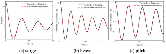
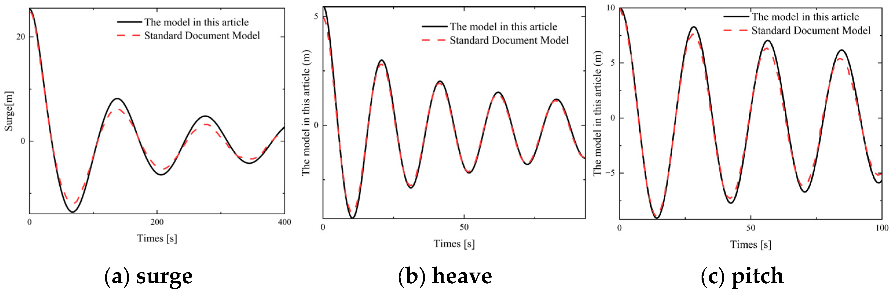
Figure 3 shows that the free decay responses of the model in the three DoFs of surge, heave, and pitch are generally in good agreement with the benchmark document. The heave time-history curves exhibit a high degree of consistency, indicating accurate modeling of vertical hydrodynamic parameters. The larger peak value in surge may be attributed to insufficient viscous damping, since the potential flow theory in AQWA does not fully account for the vortex-induced dissipation effects of columns and mooring lines, resulting in relatively low total damping. The slightly smaller pitch period and marginally higher peak value compared to the standard document are primarily due to slightly larger hydrostatic stiffness and relatively low damping levels, which align with the previous hydrostatic characteristic analysis. Overall, the response deviations across all DoFs are small, demonstrating that the model possesses excellent dynamic fidelity.
Figure 3.
Free Decay Diagram of the UM Platform and MAFWT Platform.
3.1.3. Response Amplitude Operators (RAOs)
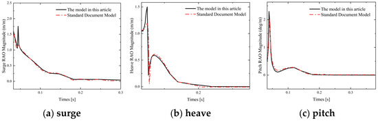
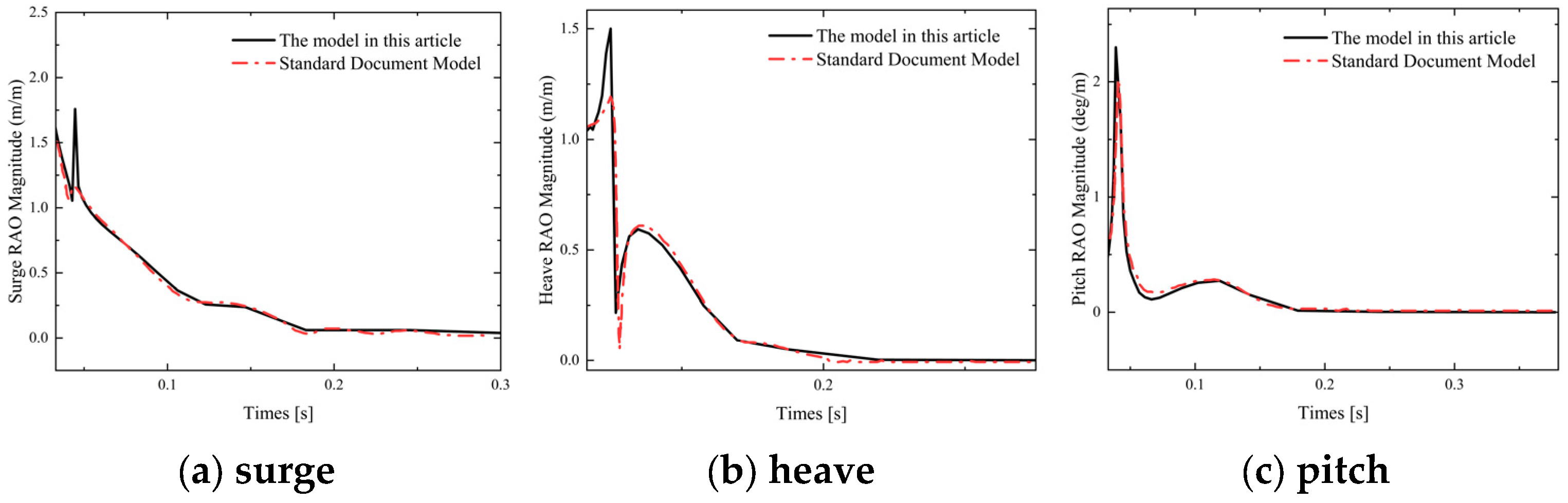
Figure 4 compares the RAOs of surge, heave, and pitch between the present model and the benchmark results. The resonance frequencies in all three degrees of freedom align closely with the reference, confirming the accuracy of the modeled hydrostatic stiffness and inertial properties. However, the peak RAO values are slightly higher than those in the benchmark, which is consistent with the earlier observation of underestimated total damping—particularly the lack of viscous contributions from columns and mooring lines in the potential-flow framework. Despite these minor amplitude discrepancies, the overall agreement in both spectral shape and resonant frequency demonstrates that the model reliably captures the platform’s linear dynamic characteristics.
Figure 4.
RAO magnitude of the UM Platform and MAFWT Platform.
Overall, the close agreement in hydrostatic stiffness, free decay periods, and RAOs with benchmark results confirms that the numerical model accurately represents the platform’s static and dynamic hydrodynamic behavior.
3.2. Fully Coupled Time Domain Analysis Under Different Stiffness Coefficients and Damping Coefficients
3.2.1. Variation Laws of Statistical Characteristics of Motion Responses with Stiffness Coefficients and Damping Coefficients
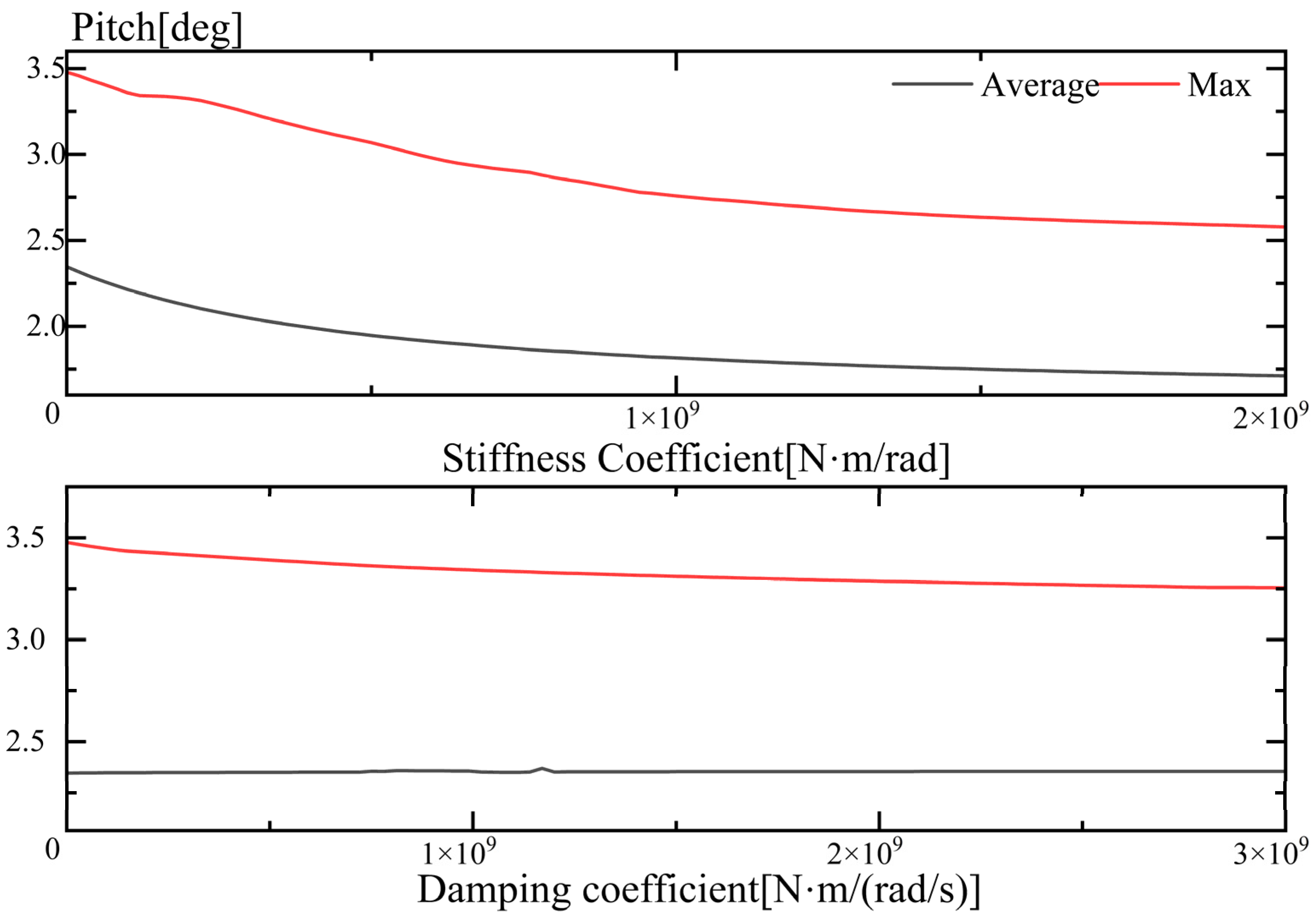
Si et al. conducted a study on the optimal control damping and stiffness of a 5 MW DeepCwind semi-submersible floating offshore wind turbine (FOWT) integrated with three point-absorber Wave-Star wave energy converters (WECs), and the corresponding optimal values were determined to be and , respectively [29]. A simplified estimation based on statics and geometric similarity yields the relationship , where denotes the overturning moment, denotes the rated power of the wind turbine and denotes the tower height. Therefore, the overturning moment acting on a 15 MW floating offshore wind turbine (FOWT) is approximately five times that of the DeepCwind FOWT. Therefore, numerical simulations were conducted under the operational conditions specified in Table 5 to systematically investigate the influence of hydrostatic stiffness and damping coefficients on the pitch motion response of the platform during normal operation. The parametric studies were conducted on the stiffness coefficient and damping coefficient respectively. Specifically, the stiffness coefficient was linearly increased from 0 to 2 × 10⁹ N·m/rad, encompassing a total of 101 sampling points with an incremental step size of 2 × 10⁷ N·m/rad. Concurrently, the damping coefficient was linearly increased from 0 to 3 × 10⁹ N·m/(rad·s), also utilizing 101 sampling points with an incremental step size of 3 × 10⁷ N·m/(rad·s).
Table 5.
Environmental condition parameters of a certain sea area in the South China Sea.
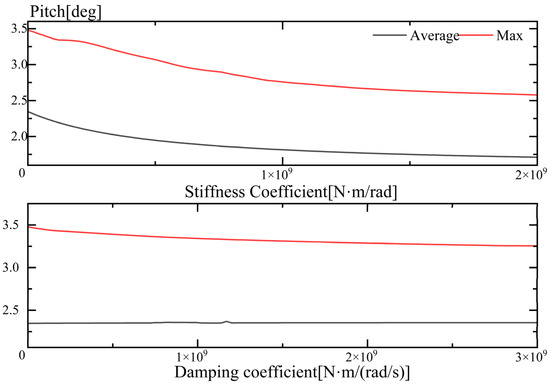
Figure 5 shows that as the stiffness coefficient increases, both the maximum and mean pitch responses exhibit a consistent decreasing trend. This indicates that higher stiffness enhances the restoring moment provided by the appendages array, effectively suppressing both the extreme and overall pitch motions of the platform. Conversely, increasing the damping coefficient leads to a reduction in the maximum pitch response, while the mean pitch amplitude remains largely unaffected. This phenomenon arises because damping primarily dissipates energy during resonant or high-amplitude events, thereby mitigating peak motions, but exerts negligible influence on the low-frequency or non-resonant components that dominate the time-averaged response.
Figure 5.
The maximum and average values of surge, heave, and pitch responses of the platform under different stiffness conditions.
3.2.2. Analysis of Motion Mechanisms
From Section 3.2.1, it can be concluded that both stiffness and damping contribute to reducing the motion response of the system. However, it must be emphasized that the underlying mechanisms by which they mitigate such responses are fundamentally distinct. To investigate the effects of stiffness and damping at the connection interface between the multi-body anti-pitching appendages and the platform on the platform’s dynamic behavior, five groups of stiffness and damping coefficients were selected respectively (as presented in Table 6 and Table 7), and comparative analyses were conducted against the floating offshore wind turbine (FOWT) without appendages installed. In this study, the UMaine VolturnUS-S semi-submersible platform is employed as the baseline configuration, and the case without appendages is denoted as “UM”.
Table 6.
Designed Stiffness Coefficients.
Table 7.
Designed Damping Coefficients.
Free Decay Tests
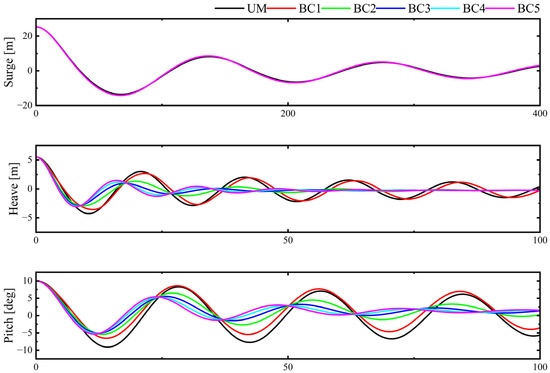
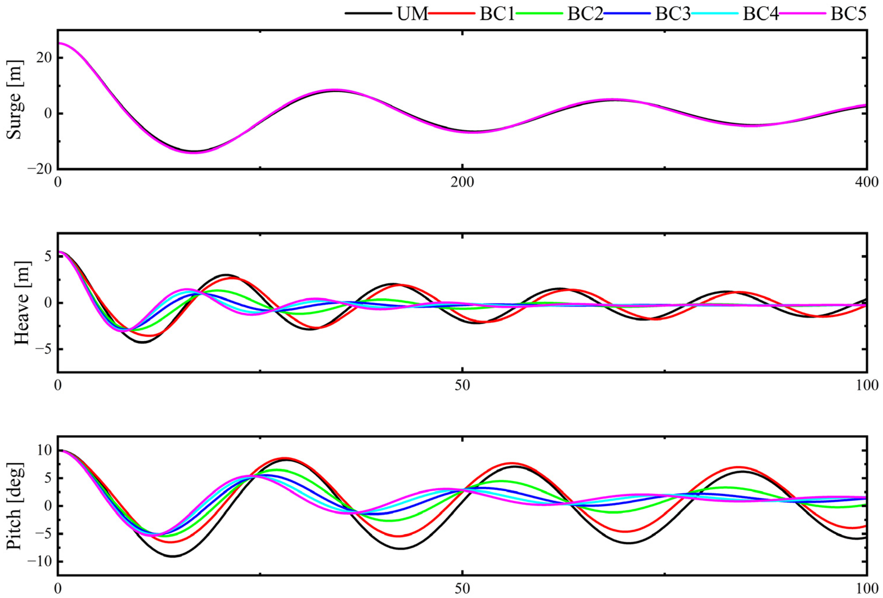
As shown in Table 8 and Table 9 and Figure 6 and Figure 7, the results indicate that for sway motion, the period remains consistently around 137 s (both with and without appendages, across all stiffness and damping configurations), and the decay rates are essentially identical. This confirms that sway dynamics are governed exclusively by the mooring system, with negligible coupling to the appendages array. In the heave degree of freedom, stiffness and damping exert different influences. An increase in connection stiffness leads to a moderate reduction in the natural period (approximately 2–3%) with nearly constant damping, indicating a mild stiffening effect on the vertical restoring characteristics. In contrast, increasing damping results in a dramatic shortening of the period (up to 23%), attributed to the indirect modification of the system’s effective stiffness or mass by damping. Concurrently, the damping ratio rises significantly (peaking at ζ ≈ 0.31% in the BC4 configuration) before slightly declining at the maximum damping level (BC5). This non-monotonic behavior suggests the existence of an optimal damping setting for maximizing vertical motion suppression; beyond this threshold, excessive damping restricts the relative motion between the platform and anti-pitching appendages, thereby reducing energy dissipation efficiency; For pitch motion, both parameters effectively modulate the system dynamics but with distinct mechanisms. Increasing stiffness induces a substantial, monotonic reduction in the natural period (from 28.18 s to 23.47 s, a 16.7% decrease) accompanied by a decrease in the damping ratio (from 2.30% to ~1.64%), reflecting the dominant role of the additional restoring moment over energy dissipation. Conversely, increasing damping moderately shortens the period (to 24.2 s, a 14.1% decrease) while monotonically elevating the damping ratio to a stable level of ζ ≈ 0.063 (6.3%). Notably, the damping-induced period reduction in pitch is comparable to that caused by stiffness adjustments, rendering damping tuning particularly effective for mitigating wave-induced resonant.
Table 8.
Comparisons of Natural Periods with Different Stiffness Coefficients.
Table 9.
Comparisons of Natural Periods with Different Damping Coefficients.
Figure 6.
Free Decay of the Platform Under Designed Stiffness Coefficient.
Figure 7.
Free Decay of the Platform Under Designed Damping Coefficient.
The equivalent linear damping ratio for each degree of freedom was quantified from the free-decay time histories using the logarithmic decrement method, a classical technique for estimating damping in lightly damped linear systems. The method relies on the exponential decay envelope of the oscillation amplitude. For a free-decay response , the damping ratio is calculated from the ratio of two successive peak amplitudes and , separated by oscillation periods:
where is the logarithmic decrement. This approach directly links the experimentally observed decay rate to the dimensionless damping ratio , a key parameter used in the subsequent dynamic analysis. The specific calculation results are shown in Table 10 and Table 11.
Table 10.
Comparisons of ζ with Different Stiffness Coefficients.
Table 11.
Comparisons of ζ with Different Damping Coefficients.
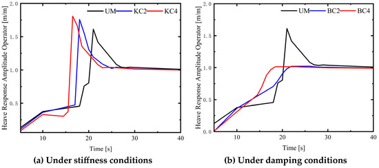
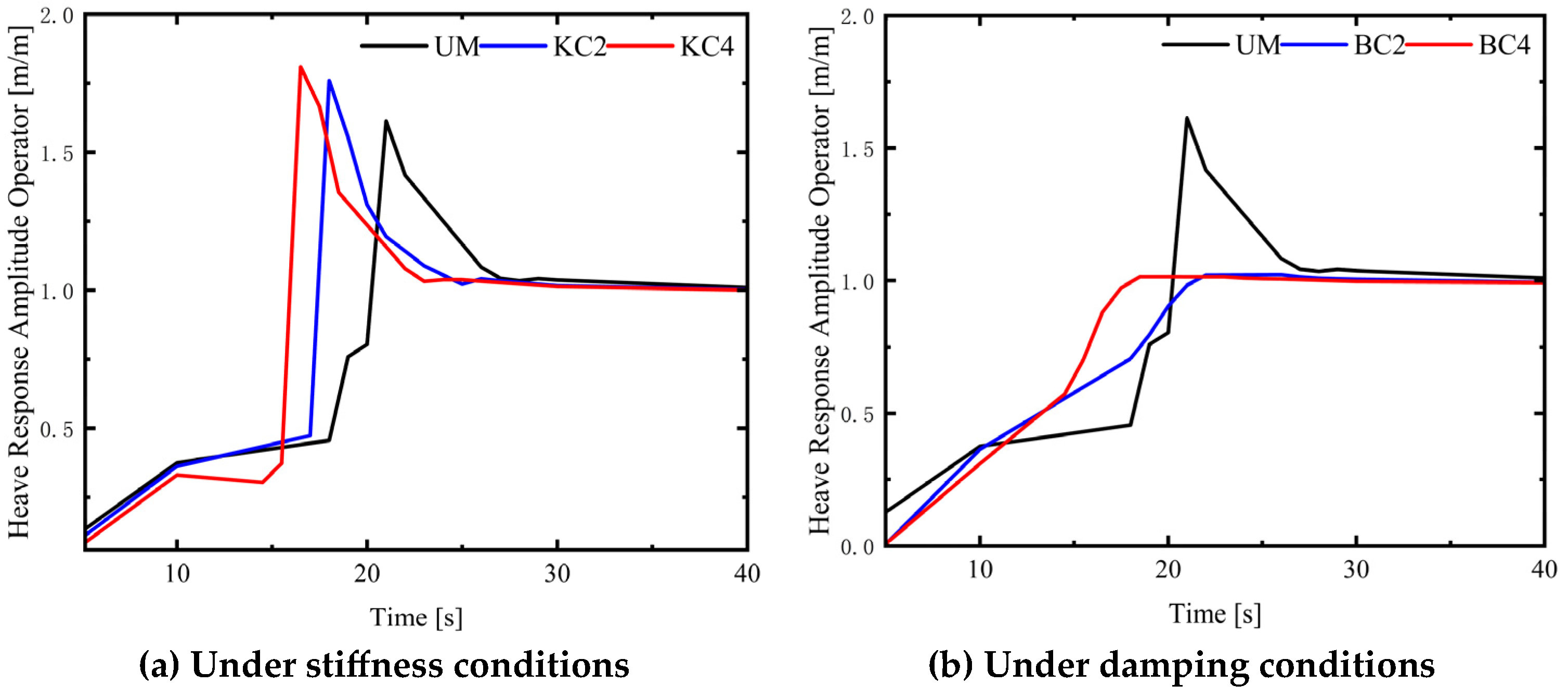
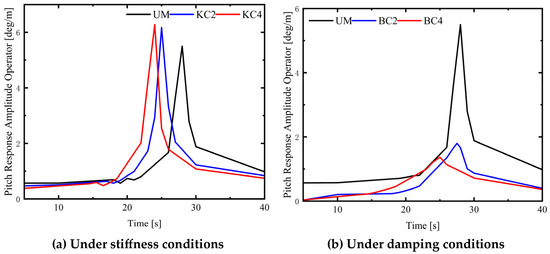
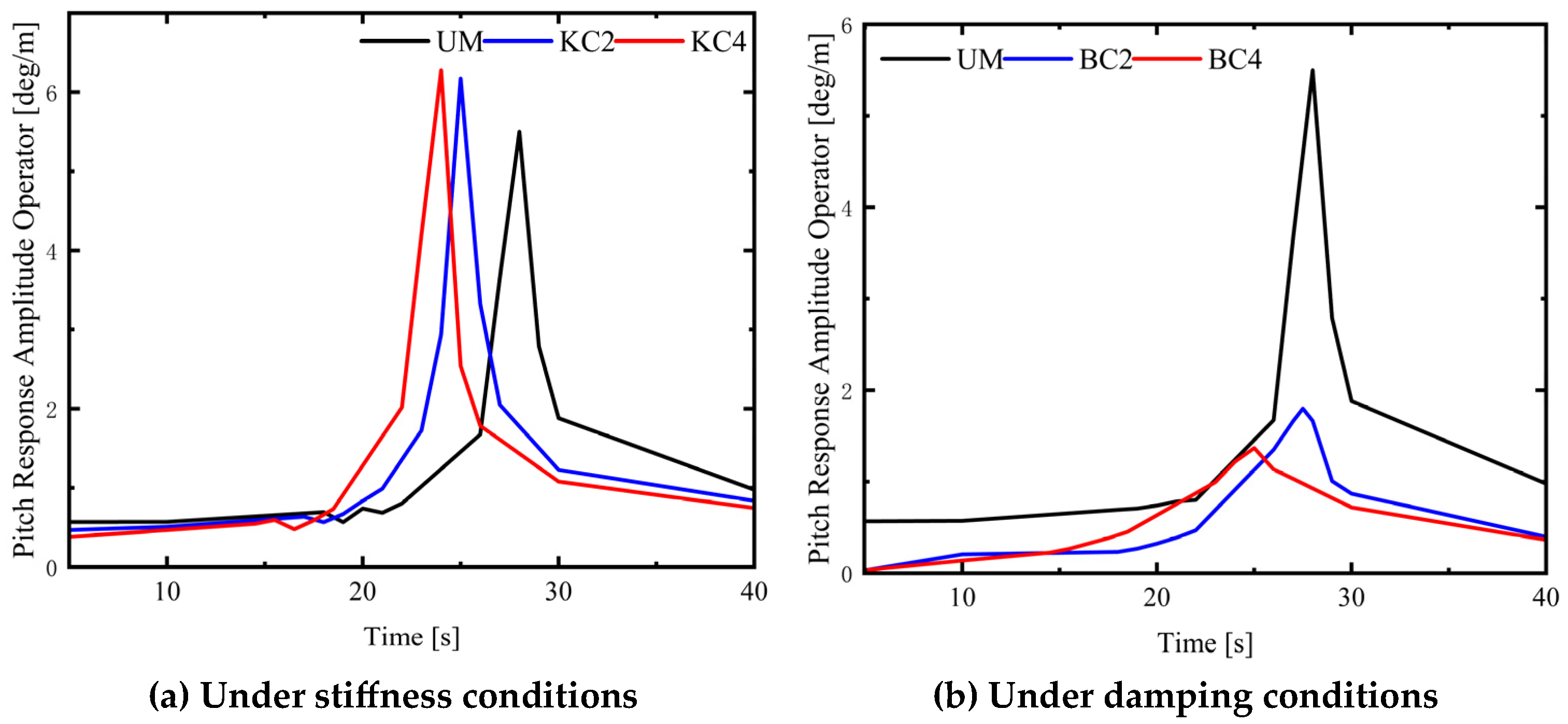
Figure 8 and Figure 9 illustrate the heave and pitch Response Amplitude Operator (RAO) curves of the MAFWT and UM under regular waves, considering varying stiffness and damping conditions. Based on linear oscillation theory, , denotes hydrostatic stiffness, denotes external stiffness, denotes the system mass, and denotes the added mass. An increase in stiffness directly enhances the system’s restoring force, leading to a higher natural frequency and a shift of the RAO peak toward shorter periods. As shown in Figure 8a and Figure 9a, variations in the stiffness coefficient primarily manifest as a period shift of the resonance peak, with a relatively minor impact on the resonance peak amplitude. Conversely, Figure 8b and Figure 9b demonstrate that changes in the damping coefficient significantly reduce the resonance amplitude. This is because near the resonance frequency, inertial forces and restoring forces cancel each other out, and the motion response is primarily balanced by damping forces. Thus, increasing the damping coefficient can substantially suppress the RAO resonance peak, effectively preventing destructive large-amplitude motions of the structure. In non-resonant regions, curves under different damping conditions nearly overlap, indicating that damping contributes minimally to non-resonant responses. Notably, due to the presence of anti-pitching appendages, variations in the damping coefficient can also influence the system’s natural frequency characteristics via the added mass effect. In summary, stiffness and damping exert distinct influence mechanisms on the MAFWT: stiffness primarily governs the system’s natural frequency characteristics, while damping mainly controls the response amplitude in the resonant region and exerts a slight influence on the natural frequency characteristics.
Figure 8.
Heave Response Amplitude Operator.
Figure 9.
Pitch Response Amplitude Operator.
3.2.3. Linear Wave and Steady Wind Condition
In accordance with the operating condition design criteria specified in Table 5, the regular wave and steady wind operating conditions are presented in Table 12, where the regular wave is defined as a fifth-order Stokes wave. To eliminate the interference of transient responses during the wind turbine startup phase, the statistical data for analysis are confined to the time window of 1000–7200 s.
Table 12.
Linear wave and steady wind environmental operating conditions.
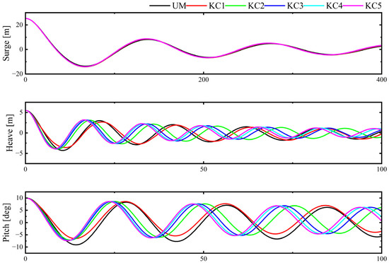
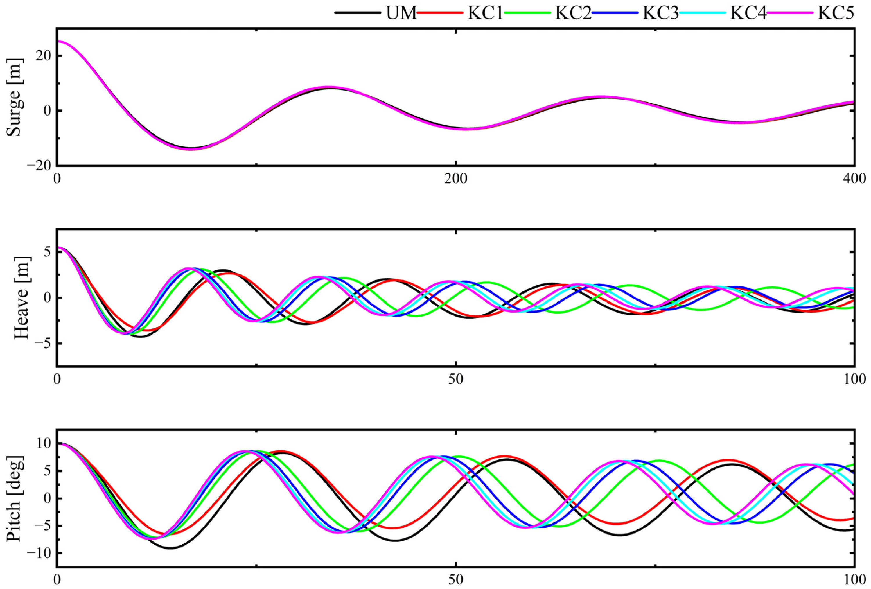
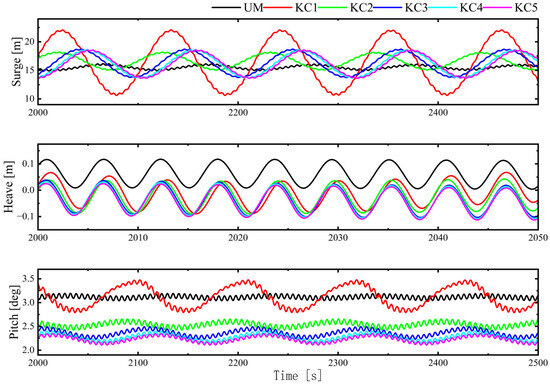
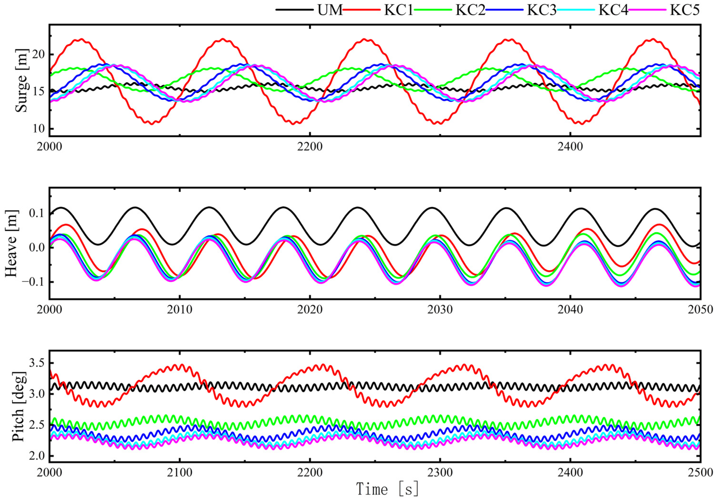
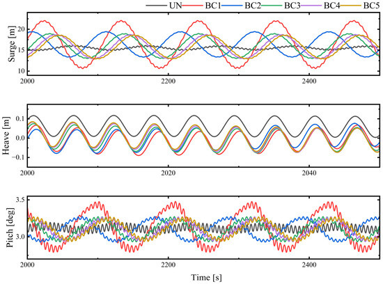
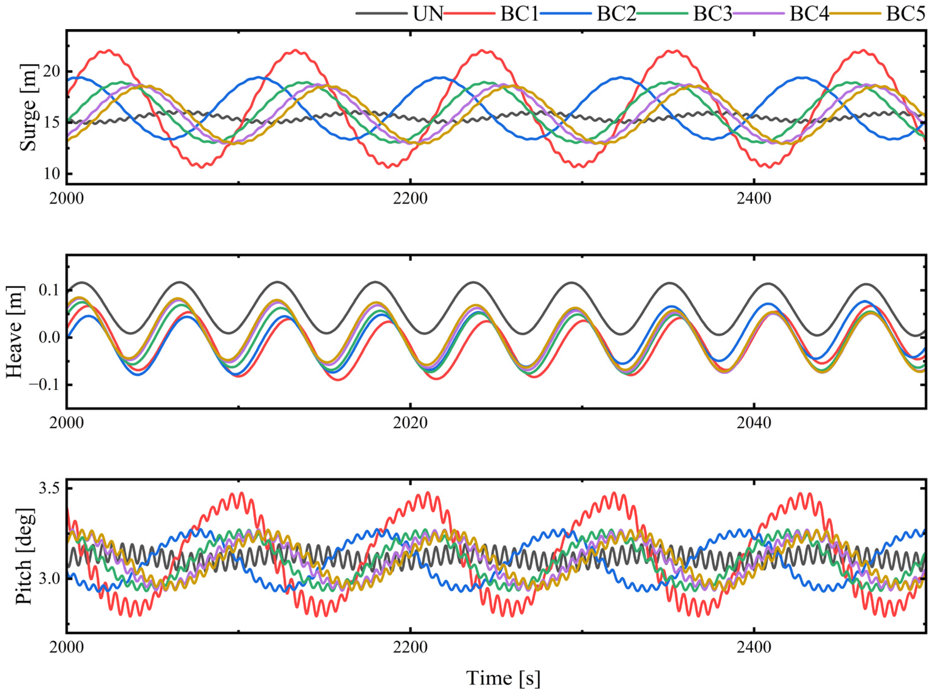
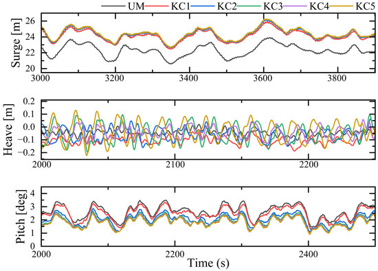
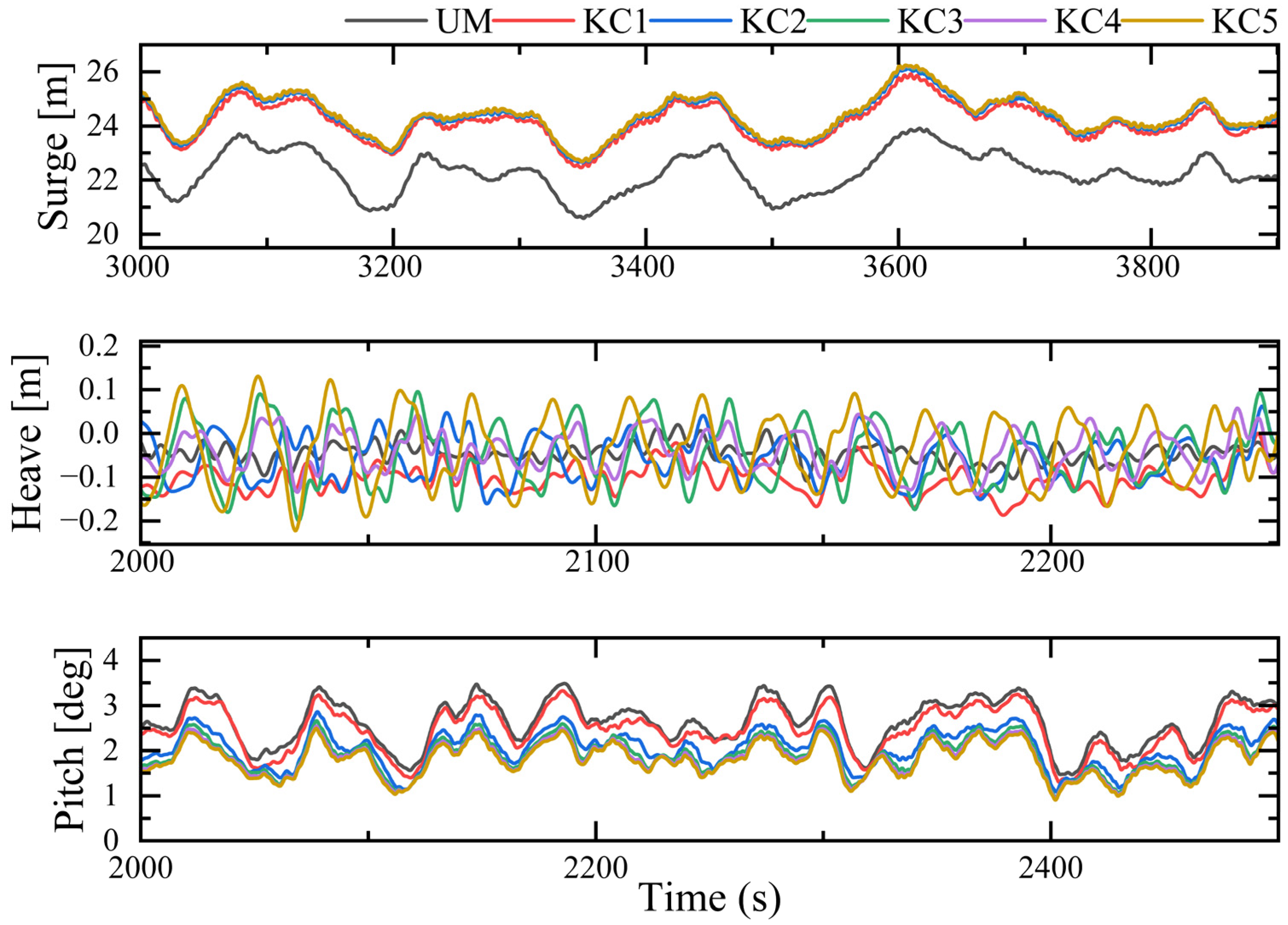
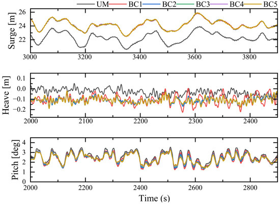
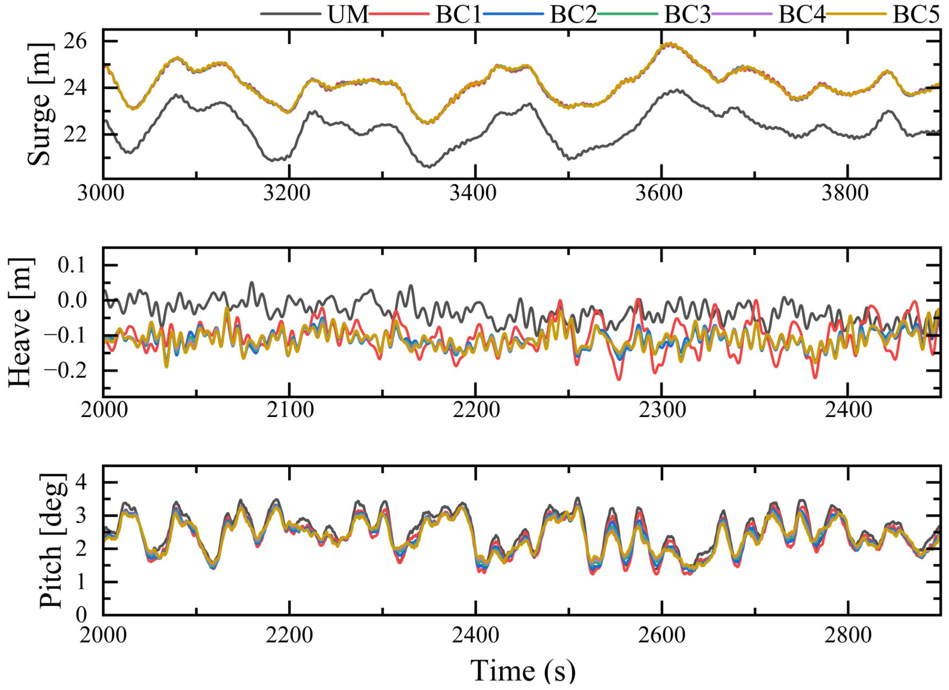
Figure 10 and Figure 11 and Table 13 and Table 14 present the motion responses of the system under the combined influence of regular waves and constant wind. It includes the platform without anti-pitching appendages (UM) alongside five configurations with anti-pitching appendages connected through gradually increasing connection stiffness (KC1–KC5) and connection damping (BC1–BC5).
Figure 10.
Time-Domain Response of the Platform Under Designed Stiffness Coefficients.
Figure 11.
Time-Domain Response of the Platform Under Designed Damping Coefficients.
Table 13.
Comparisons of with Different Stiffness Coefficients.
Table 14.
Comparisons of with Different Damping Coefficients.
The surge motion analysis indicates that the mean drift displacement (15.5–16.6 m) is predominantly governed by the aerodynamic-mooring equilibrium, showing negligible sensitivity to the anti-pitching appendage parameters. While optimized configurations (KC2–KC5 and BC2–BC5) maintain oscillation amplitudes within a controllable range (6.1–6.7 m), unconstrained cases (KC1 and BC1) exhibit severe amplification (11.67 m), attributed to uncontrolled hydrodynamic coupling. Similarly, in heave motion, the influence of stiffness and damping on oscillation amplitude is limited. However, a distinct difference emerges in static displacement: damping effectively suppresses the static heave offset to near-zero values, whereas stiffness has a minimal effect. Notably, both zero-stiffness and zero-damping configurations result in significant heave instability (0.236 m), reinforcing the necessity of constrained appendage motion.
Stiffness and damping employ distinct strategies for pitch control. Increasing stiffness (KC series) enhances the restoring moment, simultaneously suppressing both static inclination (reducing mean pitch from 3.115° to ~2.2–2.5°) and dynamic oscillation amplitude. In contrast, increasing damping (BC series) primarily dissipates kinetic energy with negligible impact on the static posture (mean pitch remains ~3.1°); notably, this leads to a slight increase (~19%) in displacement amplitude compared to the baseline. However, the critical metric for structural integrity is the pitch angular velocity, which dictates dynamic tower loads. While stiffness reduces angular velocity by 32.3%, damping proves significantly more effective, achieving a 53.5% reduction. This demonstrates that although stiffness optimizes static alignment, damping is superior for mitigating high-frequency dynamic loads.
Table 15 and Table 16 demonstrate that both stiffness and damping can significantly enhance the stability of power output while slightly improving the average power generation. Specifically, stiffness exhibits a more pronounced effect on boosting the average power generation (0.19% vs. 0.02%), whereas damping outperforms stiffness in suppressing power fluctuations (13.2% vs. 9.2%).
Table 15.
Comparison of Power Generation Output Under Different Stiffness Coefficients.
Table 16.
Comparison of Power Generation Output Under Different Damping Coefficients.
This comparison reveals the fundamental differences between the two regulatory strategies: stiffness reduces the static inclination angle and dynamic responses by enhancing the restoring moment; whereas damping, although unable to improve the static posture, dissipates kinetic energy more efficiently, thereby suppressing high-frequency dynamic loads such as angular velocity more significantly.
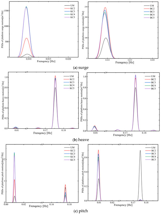
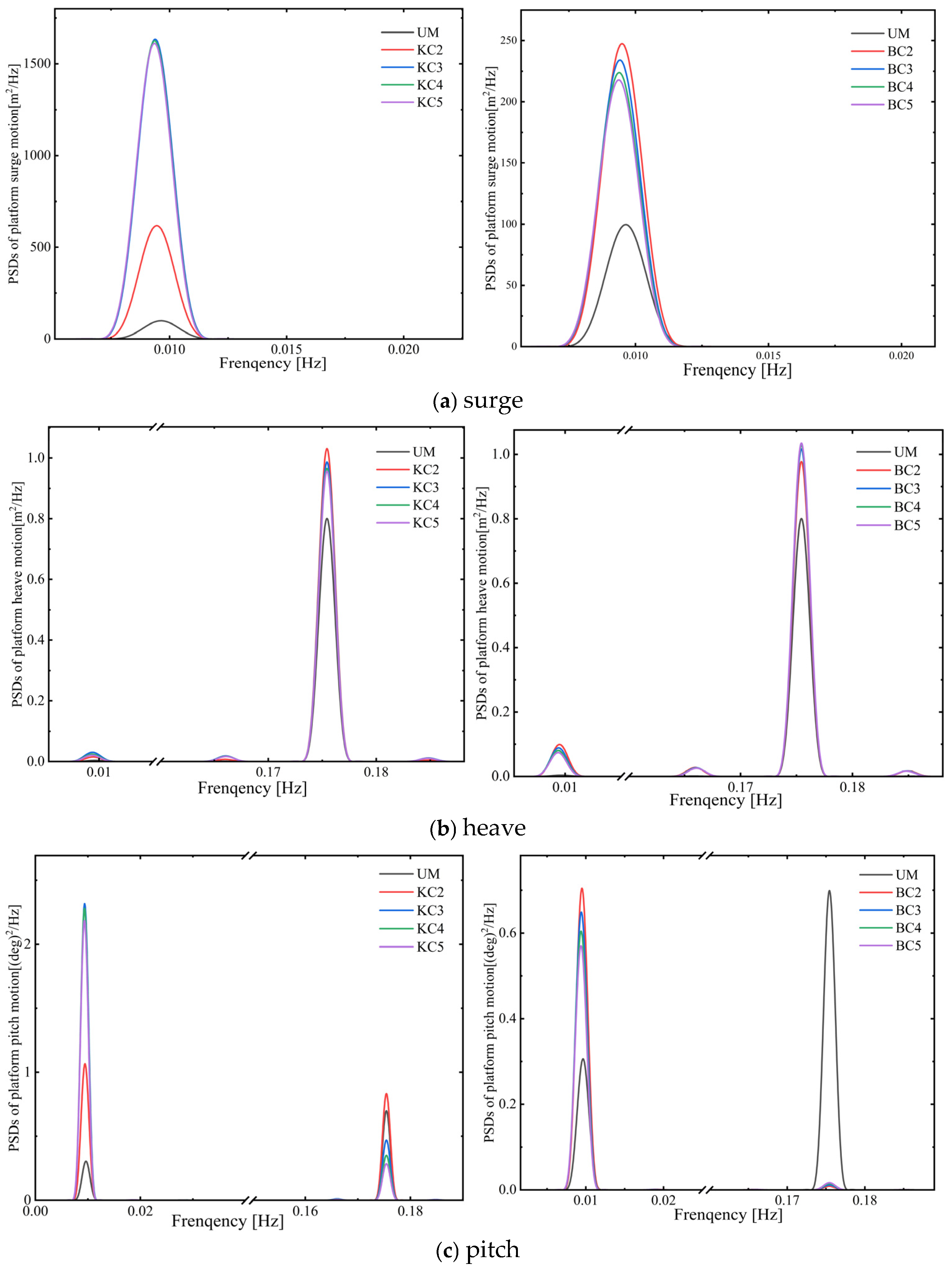
Given that the attached body remains in an unconstrained state under the KC1 and BC1 (zero stiffness and zero damping) conditions, the system response exhibits severe instability, and its frequency-domain characteristics hold no engineering reference value. Thus, this paper only analyzes the Power Spectral Density (PSD) results corresponding to the UM, KC2–KC5, and BC2–BC5 conditions.
Figure 12a presents the PSD results of the surge response. The PSD peaks of all cases are concentrated around 0.09 Hz, which corresponds to the natural frequency of the rigid-body mode of the floating platform-mooring system in the surge direction. The figure illustrates that the presence of the anti-pitching appendage excites the resonant response of the platform at its natural frequency. Moreover, the connection parameters of the anti-pitching appendage exert opposite effects on the low-frequency surge mode of the platform: increased stiffness exacerbates low-frequency resonance, whereas damping effectively suppresses the growth of its energy.
Figure 12.
Comparison of PSDs of surge, heave and pitch under Regular wave + Steady wind.
Figure 12b presents the PSD results of the heave response. A dominant peak is observed at 0.1754 Hz across all test cases, which aligns precisely with the excitation frequency of the incident regular wave—indicating that the heave response is primarily governed by first-order potential flow excitation from the wave. The results demonstrate that neither increasing the connection stiffness nor damping significantly modifies the platform’s primary response characteristics at the wave frequency. While the introduction of the appendage leads to an increase in total system energy, the response energy of the platform’s main body is reduced, as energy is dissipated at the appendage’s connection interface and through its own motion.
Figure 12c presents the PSD results of the pitch response. For the UM case, energy peaks are observed at 0.1754 Hz (wave excitation frequency) and 0.009 Hz (ultra-low frequency). Increasing the connection stiffness effectively attenuates the wave-frequency dynamic response but concurrently induces more pronounced low-frequency fluctuations in the static pitch angle, reflecting the energy transfer mechanism of stiffness—where energy is shifted from the wave-frequency band to the low-frequency band. In contrast, increasing damping not only substantially eliminates the influence of wave-frequency dynamic excitation but also simultaneously reduces the amplitude of low-frequency components. This further explains why the BC series exhibits the lowest pitch angular velocity amplitude (with a reduction of up to 53.5%) and the smallest power output fluctuations in the time domain.
3.2.4. Nonlinear Waves and Turbulent Wind Conditions
As shown in Table 17 and Table 18 and Figure 13 and Figure 14, under irregular wave and turbulent wind conditions, the pitch amplitude of the UM configuration is 3.250, with an angular velocity amplitude reaching 0.597 deg/s—reflecting intense dynamic loading induced by random excitation. For the KC1 and BC1 cases (where the appendage is in a freely connected state with the platform), not only was platform motion not suppressed, but unsteady hydrodynamic coupling was triggered by the free drift of the appendage. This resulted in a pitch amplitude as high as 3.201°, a heave amplitude of 0.332 m, and no improvement in power fluctuations (with a standard deviation of approximately 758.9 W), fully demonstrating that appendages lacking effective connection constraints degrade system stability.
Table 17.
Comparisons of with Different Stiffness Coefficients.
Table 18.
Comparisons of with Different Damping Coefficients.
Figure 13.
Time-Domain Response of the Platform Under Designed Stiffness Coefficients.
Figure 14.
Time-Domain Response of the Platform Under Designed Damping Coefficients.
In contrast, configurations with effective stiffness (KC2–KC5) or damping (BC2–BC5) both enhanced performances. Specifically, the stiffness schemes reduced the average pitch angle from 2.463° to 1.678° by increasing the restoring moment, but exhibited limited suppression of dynamic responses, and heave amplitude increased with increasing stiffness. Meanwhile, the damping schemes significantly reduced the pitch angular velocity by 25.5% to 0.445 deg/s while maintaining the average pitch angle at approximately 2.30°. In summary, stiffness significantly alters the static attitude of the platform to adjust the windward angle of the wind turbine, whereas damping enhances platform stability while preserving the original operational attitude. As can be seen from Table 19 and Table 20, increasing stiffness and damping led to respective increases of 0.18% and 0.12% in the average power output, which constitutes a relatively notable gain [30].
Table 19.
Comparison of Power Generation Output Under Different Stiffness Coefficients.
Table 20.
Comparison of Power Generation Output Under Different Damping Coefficients.
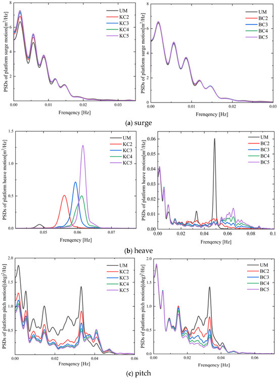
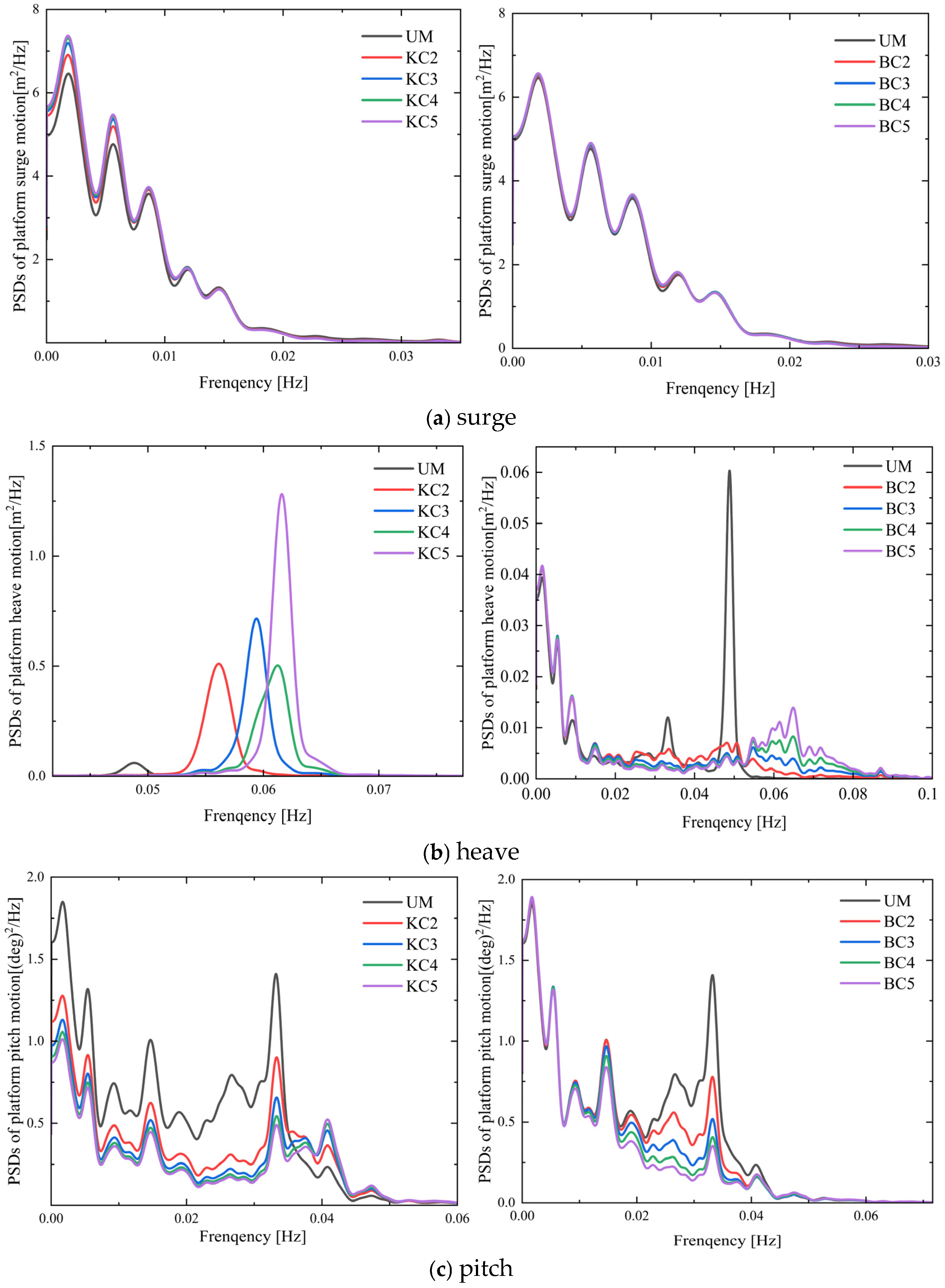
The PSD analysis in Figure 15 shows that under the combined action of irregular waves and turbulent wind, the surge motion of the platform is dominated by the second-order difference-frequency wave force (i.e., slow-drift force). In this context, the effects of connection parameters on the surge response exhibit distinct discrepancies. Damping configurations (BC2–BC5) exert a relatively weak inhibitory effect on surge motion, with the energy distribution of the power spectral density (PSD) in the ultra-low frequency band (0.002–0.02 Hz) remaining largely unchanged. In contrast, stiffness configurations (KC2–KC5) lead to a significant increase in the energy peak within this frequency band, which aligns with the trend observed in Table 17—where the standard deviation of the surge response rises with increasing stiffness. This phenomenon indicates that the introduction of connection stiffness for the appendage alters the low-frequency dynamic characteristics of the platform-mooring system, potentially amplifying the excitation effect of slow-drift forces indirectly by enhancing overall stiffness or mass coupling. In the heave direction, increasing stiffness slightly amplifies the total energy of the heave response and induces a shift in the frequency of the main energy peak, implying a modulating effect on the vertical modes of the system. Conversely, damping significantly reduces the amplitude of the main heave PSD peak, demonstrating its effective capacity to dissipate high-frequency hydrodynamic disturbances. For the critical pitch degree of freedom, both strategies effectively suppress low-frequency energy. Increased stiffness notably attenuates energy across all frequency bands, which stems from the additional anti-overturning moment provided by the appendage—directly counteracting the static and quasi-static overturning effects induced by wind thrust and slow-drift wave forces. Enhanced damping, on the other hand, exerts a more pronounced inhibitory effect on energy within the same frequency band (0.02–0.04 Hz). By continuously dissipating kinetic energy, it effectively blocks the transmission and accumulation of low-frequency disturbances in the platform-appendage system, thereby significantly improving the stability of pitch motion.
Figure 15.
Comparison of PSDs of surge, heave and pitch under Irregular wave + Turbulent wind.
4. Conclusions
This study systematically investigates the mechanisms by which stiffness (K) and damping (B) parameters influence the dynamic performance of the multi-body anti-pitching semi-submersible floating offshore wind turbine (MAFWT) via a high-fidelity fully coupled numerical model. Results indicate that while both stiffness and damping effectively suppress platform pitching motion, their operational mechanisms are fundamentally distinct, with each exhibiting unique advantages across different operating conditions.
1. Stiffness primarily acts by enhancing the system’s restoring moment. Under regular wave and steady wind conditions, increasing connection stiffness from 0 to 2 × 10⁹ N·m/rad reduced the platform’s mean pitch angle significantly from 3.115° to 2.230°, alongside a decrease in pitching oscillation amplitude from 0.317° to 0.288°. This confirms that higher stiffness concurrently mitigates static pitch offset and overall dynamic response. However, excessive stiffness induces adverse effects: under irregular wave and turbulent wind conditions, it amplifies low-frequency surge motion driven by second-order difference-frequency wave forces (slow-drift forces), as evidenced by a rising standard deviation of surge response with increasing stiffness. Thus, stiffness tuning requires a trade-off between pitching suppression and low-frequency slow-drift amplification. When designing for sites with significant low-frequency wave energy, stiffness tuning must be subordinate to surge stability constraints, potentially accepting a slightly higher mean pitch angle to avoid resonance-induced surge amplification.
2. Damping functions primarily through kinetic energy dissipation to suppress dynamic loads. It has negligible impact on static equilibrium posture (mean pitch angle remained stable at ~3.10° under regular wave conditions) but exerts a pronounced inhibitory effect on dynamic responses. Under regular wave and steady wind conditions, increasing the damping coefficient to 3 × 10⁹ N·m/(rad·s) reduced the pitching angular velocity amplitude from the baseline 0.127 deg/s to 0.059 deg/s, a maximum reduction of 53.5%. Even under complex irregular wave and turbulent wind conditions, high damping configurations performed favorably, reducing pitching angular velocity amplitude by 25.5%, and the standard deviation decreased by 16.4%. Frequency-domain analysis further revealed that damping not only eliminates wave-frequency dynamic excitation but also attenuates low-frequency component energy, thereby comprehensively enhancing platform dynamic stability. Notably, variations in the damping coefficient can also influence the natural frequency characteristics of the system via the added mass effect, which can serve as a resonance avoidance design strategy. Given that damping variations effectively modify the apparent natural frequency of the system via the added mass effect, high-damping configurations can be employed in design not only to suppress peak responses but also to shift the system’s natural frequency away from critical wave excitation bands.
It is important to acknowledge the limitations of the current study. The numerical framework employed relies on potential flow theory (AQWA) coupled with blade element momentum theory (OpenFAST). While validated against benchmark data for the baseline platform, this approach inherently simplifies viscous effects and complex flow separations around the multi-body appendages. The proposed MAFWT configuration has not yet been validated against experimental tank test data or higher-fidelity Computational Fluid Dynamics (CFD) simulations. Consequently, the absolute values of motion suppression and power enhancement reported herein should be interpreted as relative trends rather than precise predictions for full-scale deployment.
In conclusion, stiffness is a critical parameter for regulating platform static posture and overall restoring capacity, while damping serves as a core element for suppressing high-frequency dynamic loads, reducing fatigue damage, and stabilizing power output. In engineering design, parameter optimization should align with specific objectives: if the primary goal is to reduce static pitch angle and optimize wind turbine alignment with the wind, stiffness enhancement should be prioritized; if the core requirement is to minimize dynamic loads to critical components (e.g., towers), damping parameter optimization should be emphasized. However, this study only investigated the influence of stiffness–damping decoupling on system motion. In subsequent work, we will explore the combined effects of stiffness and damping, and design experiments to examine the nonlinear phenomena associated with this novel concept.
Author Contributions
Conceptualization, R.F., Y.S., T.P., J.F. and T.F.; Methodology, R.F., Y.S., T.P., J.F. and T.F.; Software, R.F., Y.S., T.P. and J.F.; Validation, R.F., Y.S. and T.P.; Formal analysis, R.F., Y.S., T.P. and J.F.; Investigation, R.F., Y.S., T.P., J.F. and T.F.; Resources, R.F.; Data curation, R.F. and Y.S.; Writing—original draft, R.F., Y.S. and T.P.; Writing—review & editing, R.F., Y.S., T.P., J.F. and T.F.; Visualization, R.F., Y.S. and J.F.; Supervision, R.F. and T.F.; Project administration, R.F. and T.F.; Funding acquisition, R.F. and T.F. All authors have read and agreed to the published version of the manuscript.
Funding
This research was funded by the Natural Science Foundation of Guangdong Province, China with grant number 2022B1515020071; the Natural Science Foundation of China with grant number 52522112; the GJYC program of Guangzhou with grant number 2024A04J6297 and 2024D03J0022.
Data Availability Statement
The original contributions presented in this study are included in the article. Further inquiries can be directed to the corresponding author.
Conflicts of Interest
Author Tianguo Pan was employed by the company New Energy Holdings Co., Ltd. The remaining authors declare that the research was conducted in the absence of any commercial or financial relationships that could be construed as a potential conflict of interest.
Abbreviations
The following abbreviations are used in this manuscript:
| MAFWT | Multi-body Anti-pitching Floating Wind Turbine |
| FOWT | Floating offshore wind turbine |
| F2A | FAST-to-AQWA simulation framework |
| COG | Center of gravity |
| COB | Center of buoyancy |
| BWS | Big wave-star WEC |
| STC | Spar-Torus combination |
| WEC | Wave energy converter |
| OWS | OpenFAST and WEC-sim |
| PTO | power take-off |
| BEM | Blade Element Momentum |
| DLL | Dynamic link library |
| DOF | Degree of freedom |
| RAO | Response Amplitude Operator |
| NREL | National Renewable Energy Laboratory |
| UM | UMaine VolturnUS-S semi-submersible platform |
| PSD | Power Spectral Density |
| Std | Standard deviation |
References
- Chen, C.; Ma, Y.; Fan, T. Review of model experimental methods focusing on aerodynamic simulation of floating offshore wind turbines. Renew. Sustain. Energy Rev. 2022, 157, 112036. [Google Scholar] [CrossRef] [Scilit]
- Jonkman, J. Dynamics Modeling and Loads Analysis of an Offshore Floating Wind Turbine; Technical Report; National Renewable Energy Laboratory (NREL): Golden, CO, USA, 2007. [Google Scholar]
- Lamei, A.; Hayatdavoodi, M.; Riggs, H.R.; Ertekin, R.C. Dynamic response of multi-unit floating offshore wind turbines to wave, current, and wind loads. J. Renew. Sustain. Energy 2024, 16, 043307. [Google Scholar] [CrossRef] [Scilit]
- Ghamati, E.; Kariman, H.; Hoseinzadeh, S. Experimental and Computational Fluid Dynamic Study of Water Flow and Submerged Depth Effects on a Tidal Turbine Performance. Water 2023, 15, 2312. [Google Scholar] [CrossRef] [Scilit]
- Zhu, H.; Hu, C. A study on control of wave energy converter for motion suppression of semi-submersible. IFAC PapersOnLine 2016, 49, 380–385. [Google Scholar] [CrossRef] [Scilit]
- Yang, J.; He, E.M.; Hu, Y.Q. Dynamic modeling and vibration suppression for an offshore wind turbine with a tuned mass damper in floating platform. Appl. Ocean Res. 2019, 83, 21–29. [Google Scholar] [CrossRef] [Scilit]
- Ou, J.; Long, X.; Li, Q.S.; Xiao, Y.Q. Vibration control of steel jacket offshore platform structures with damping isolation systems. Eng. Struct. 2007, 29, 1525–1538. [Google Scholar] [CrossRef] [Scilit]
- Cheng, Z.; Wang, K.; Gao, Z.; Moan, T. Dynamic response analysis of three floating wind turbine concepts with a two-bladed Darrieus rotor. J. Ocean Wind Energy 2015, 2, 213–222. [Google Scholar] [CrossRef] [Scilit]
- Allen, C.; Viselli, A.; Dagher, H.; Goupee, A.; Gaertner, E.; Abbas, N.; Hall, M.; Barter, G. Definition of the UMaine VolturnUS-S Reference Platform Developed for the IEA Wind 15-Megawatt Offshore Reference Wind Turbine; University of Maine: Orono, ME, USA; National Renewable Energy Laboratory: Golden, CO, USA, 2020. [Google Scholar]
- Fan, T.; Fang, J.; Yan, X.; Ma, Y. Numerical Study of an Innovative Concept for a Multibody Anti-Pitching Semi-Submersible Floating Wind Turbine. J. Mar. Sci. Eng. 2024, 12, 553. [Google Scholar] [CrossRef] [Scilit]
- Yang, Y.; Liang, C.; Liu, S.; Jiang, J.; Huang, Z.; Liang, C.; Ou, W.; Tao, T.; Chen, M. Frequency and Time Domain Simulations of a 15 MW Floating Wind Turbine Integrating with Multiple Flap-Type WECs. Sustainability 2025, 17, 2448. [Google Scholar] [CrossRef] [Scilit]
- Wei, Z.; Cao, F.; Cao, C.; Han, Z.; Shi, H.; Ji, T. Experimental study on the effects of an array of concentric wave energy converters on the dynamic of semi-submersible floating wind turbine. Renew. Energy 2025, 242, 122495. [Google Scholar] [CrossRef] [Scilit]
- Cheng, Z.; Wen, T.R.; Ong, M.C.; Wang, K. Power performance and dynamic responses of a combined floating vertical axis wind turbine and wave energy converter concept. Energy 2019, 171, 190–204. [Google Scholar] [CrossRef] [Scilit]
- Kamarlouei, M.; Gaspar, J.F.; Calvario, M.; Hallak, T.S.; Mendes, M.J.G.C.; Thiebaut, F.; Soares, C.G. Experimental analysis of wave energy converters concentrically attached on a floating offshore platform. Renew. Energy 2020, 152, 1171–1185. [Google Scholar] [CrossRef] [Scilit]
- Luan, C.; Michailides, C.; Gao, Z.; Moan, T. Modeling and analysis of a 5 MW semi-submersible wind turbine combined with three flap-Type wave energy converters. In Proceedings of the 33rd International Conference on Ocean, Offshore and Arctic Engineering, San Francisco, CA, USA, 8–13 June 2014; Volume 9B. [Google Scholar]
- Li, L.; Gao, Y.; Yuan, Z.; Day, S.; Hu, Z. Dynamic response and power production of a floating integrated wind, wave and tidal energy system. Renew. Energy 2018, 116, 412–422. [Google Scholar] [CrossRef] [Scilit]
- Gaspar, J.F.; Kamarlouei, M.; Thiebaut, F.; Soares, C.G. Compensation of a hybrid platform dynamics using wave energy converters in different sea state conditions. Renew. Energy 2021, 177, 871–883. [Google Scholar] [CrossRef] [Scilit]
- Kamarlouei, M.; Gaspar, J.F.; Calvario, M.; Hallak, T.S.; Mendes, M.J.; Thiebaut, F.; Soares, C.G. Experimental study of wave energy converter arrays adapted to a semi-submersible wind platform. Renew. Energy 2022, 188, 145–163. [Google Scholar] [CrossRef] [Scilit]
- Zhang, H.; Zhang, N.; Cao, X. Conceptualization and dynamic response of an integrated system with a semi-submersible floating wind turbine and two types of wave energy converters. Ocean Eng. 2023, 269, 113517. [Google Scholar] [CrossRef] [Scilit]
- Ghafari, H.R.; Ghassemi, H.; Abbasi, A.; Vakilabadi, K.A.; Yazdi, H.; He, G. Novel concept of hybrid wavestar-floating offshore wind turbine system with rectilinear arrays of WECs. Ocean Eng. 2022, 262, 112253. [Google Scholar] [CrossRef] [Scilit]
- Si, Y.; Chen, Z.; Zeng, W.; Sun, J.; Zhang, D.; Ma, X.; Qian, P. The influence of power-take-off control on the dynamic response and power output of combined semi-submersible floating wind turbine and point-absorber wave energy converters. Ocean Eng. 2021, 227, 108835. [Google Scholar] [CrossRef] [Scilit]
- Ghafari, H.R.; Ghassemi, H.; He, G. Numerical study of the Wavestar wave energy converter with multi-point-absorber around DeepCwind semisubmersible floating platform. Ocean Eng. 2021, 232, 109177. [Google Scholar] [CrossRef] [Scilit]
- Wang, T.; Li, D.; Greaves, D.; Hann, M.; Zhu, K.; Li, Y.; Gong, H.; Tao, J.; Cao, F.; Shi, H. Numerical modelling and PTO damping optimization of an IEA-15-MW-VolturnUS-WEC hybrid system in real sea states. Energy 2025, 330, 136693. [Google Scholar] [CrossRef] [Scilit]
- Borg, M.; Collu, M.; Brennan, F.P. Use of a Wave Energy Converter as a Motion Suppression Device for Floating Wind Turbines. Energy Procedia 2013, 35, 223–233. [Google Scholar] [CrossRef] [Scilit]
- Faltinsen, O. Sea Loads on Ships and Offshore Structures; Cambridge University Press: Cambridge, UK, 1993. [Google Scholar]
- Gonzalez, A.; Munduate, X. Unsteady modelling of the oscillating S809 aerofoil and NREL phase VI parked blade using the Beddoes-Leishman dynamic stall model. J. Phys. Conf. Ser. 2007, 75, 012020. [Google Scholar] [CrossRef] [Scilit]
- Yang, Y.; Bashir, M.; Michailides, C.; Li, C.; Wang, J. Development and application of an aero-hydro-servo-elastic coupling framework for analysis of floating offshore wind turbines. Renew. Energy 2020, 161, 606–625. [Google Scholar] [CrossRef] [Scilit]
- Ma, Y.; Chen, C.; Fan, T.; Yan, X.; Lu, H. Research on motion inhibition method using an innovative type of mooring system for spar floating offshore wind turbine. Ocean Eng. 2021, 223, 108644. [Google Scholar] [CrossRef] [Scilit]
- Liu, H.; Chen, M.; Han, Z.; Zhou, H.; Li, L. Feasibility study of a novel open ocean aquaculture ship integrating with a wind turbine and an internal turret mooring system. J. Mar. Sci. Eng. 2022, 10, 1729. [Google Scholar] [CrossRef] [Scilit]
- Yang, Y.; Sun, K.; Liu, Y.; Zhang, J.; Zhang, H.; Zhu, R.; Yao, H.-D. Coupled numerical framework for wind-wave-to-wire energy conversion in floating hybrid wind-wave systems. Appl. Energy 2026, 403, 127106. [Google Scholar] [CrossRef] [Scilit]

Disclaimer/Publisher’s Note: The statements, opinions and data contained in all publications are solely those of the individual author(s) and contributor(s) and not of MDPI and/or the editor(s). MDPI and/or the editor(s) disclaim responsibility for any injury to people or property resulting from any ideas, methods, instructions or products referred to in the content. |
© 2026 by the authors. Licensee MDPI, Basel, Switzerland. This article is an open access article distributed under the terms and conditions of the Creative Commons Attribution (CC BY) license.