


Abstract
This work focuses on evaluating the fatigue characteristics of a 66 kV wet-type submarine cable. The analysis incorporates realistic offshore environmental conditions and considers installation through a flexible pull-in system. The target system was deployed at the Southwest Offshore Wind Farm in Korea, where the structural response of the cable is governed by combined wave- and wind-induced loading. To determine the ultimate limit state (ULS) behavior of the cable arranged in the flexible pull-in installation configuration, a global dynamic analysis was initially performed, from which time-dependent displacement histories were extracted under site-specific metocean conditions. The results indicate that lateral wave-induced loading dominates the global response owing to the vertically suspended configuration of the flexible pull-in installation system. A detailed local fatigue analysis was performed based on the critical loading scenarios identified from the global analysis. Prior to the fatigue evaluation, a numerical modeling approach for the local analysis of the 66 kV wet-type submarine cable was developed and validated through comparisons with experimental tensile test results. The developed numerical model successfully captured the axial stiffness characteristics and deformation response of the cable, demonstrating a discrepancy of less than 1% between the numerical predictions and experimental measurements. Fatigue analyses were performed for 120 displacement-based time-history loading cases derived from the global dynamic response. The results show that the fatigue damage is predominantly concentrated in the steel-wire armor, particularly near the fixed boundary region, identifying it as the governing fatigue-critical component. In addition, a parametric study of the wire-armor helix angle revealed that increasing the helix angle significantly improved the fatigue life by enhancing the bending flexibility and reducing the stress concentration under transverse loading. These findings provide practical insights into the fatigue-resistant design and optimization of wet-type submarine cables installed using flexible pull-in installation systems in floating offshore wind applications.
1. Introduction
Technological innovation in offshore energy production has progressed markedly in recent decades. Major developments include floating wind turbine systems and wave-energy conversion technologies. Among these, offshore wind power has become one of the most promising renewable energy sources, garnering widespread interest from both researchers and industry stakeholders [1,2,3,4]. Offshore wind power is increasingly deployed worldwide as a stable and sustainable energy source [5]. To maximize the utilization of offshore wind resources, wind farms are expanding into deeper and more remote offshore regions, where wind conditions are more favorable and turbines are typically supported by floating platforms.
Electrical energy generated by offshore wind farms is delivered to land-based substations through submarine power cables (SPCs) [6]. Floating wind platforms necessitate the use of dynamic power cables (DPCs), a specialized form of SPC designed to accommodate platform motion. Typically, one end of the cable is secured to the floating structure, while the other is positioned on the seabed. Unlike static subsea cables, DPCs are continuously influenced by cyclic loads induced by waves, currents, and structural movement. These actions generate combined mechanical effects such as bending, axial stretching, and torsion [7]. SPCs are commonly classified into dry- and wet-type designs based on their water-ingress protection strategy and the configuration of the insulation system [8]. Wet-type SPCs do not incorporate rigid metallic water barriers, which provide significantly improved flexibility and reduced bending stiffness compared with dry-type designs [8]. These characteristics are particularly advantageous in dynamic applications, such as floating offshore wind platforms, where cables experience repeated cyclic deformation. As a result, wet-type cables generally exhibit superior fatigue performance under cyclic loading conditions. In contrast, dry-type SPCs employ metallic water barriers to prevent moisture ingress into the insulation system [9]. While this design enhances long-term electrical reliability, the presence of metallic barriers increases the overall stiffness and bending rigidity of the cable. From a mechanical perspective, this increased stiffness can lead to higher bending stresses under cyclic loading, potentially reducing fatigue performance in dynamic environments. Despite their mechanical advantages, wet-type SPCs present challenges related to long-term insulation aging and water-treeing phenomena owing to allowable water ingress. These issues must be carefully addressed during the design stage through conservative electrical stress limits, appropriate material selection, and stringent quality control during manufacturing. Nevertheless, wet-type SPCs are increasingly adopted in medium-voltage dynamic applications, where mechanical flexibility and fatigue resistance are critical design considerations.
DPCs are subjected to repeated cyclic loading arising from environmental forces and floating platform movements. This sustained loading condition heightens their susceptibility to fatigue damage and positions fatigue failure as a critical challenge within the offshore wind industry [10]. Substantial research efforts have been devoted to investigating the fatigue behavior of DPCs. In general, fatigue assessment frameworks for DPCs couple system-level (global) dynamic analyses with damage accumulation models, where time-varying tension and curvature histories obtained from cable response analyses are converted into fatigue damage metrics. Recent studies have highlighted that global response-driven fatigue evaluation remains the baseline methodology for dynamic cable design, while ongoing research aims to improve the load prediction fidelity and uncertainty treatment under site-specific metocean conditions. Early investigations largely emphasized global dynamic analyses at the system scale to quantify tension and curvature behavior in cables connected to floating wind turbines. Thies et al. [11] conducted a detailed study on a 66 kV DPC configured in a lazy-wave layout. Their findings indicated that the motion of the floating platform was the principal factor governing cable loading and fatigue accumulation. Similarly, Bakken [12] evaluated the fatigue life of a DPC using coupled numerical tools and identified regions with the maximum tension range as fatigue-critical locations. Zhao et al. [13] compared lazy- and double-wave configurations and reported that the hang-off point consistently governed fatigue life, while the secondary buoyancy section played a critical role in double-wave systems. Vortex-induced vibration (VIV) has also been recognized as a fatigue-critical mechanism in current-dominated environments. Shim [14] proposed practical fatigue assessment procedures that decomposed the workflow into static configuration analysis, modal characterization, VIV response, and fatigue calculation. These approaches are particularly relevant for cable sections exposed to sustained shear currents, where high-cycle oscillations can govern fatigue life, even when the wave-induced curvature is moderate.
Several studies have emphasized the importance of cable configuration optimization and installation geometry. Rentschler et al. [15] proposed a design optimization framework for dynamic inter-array cables, incorporating fatigue life, extreme load performance, and economic considerations. Their results showed that optimized buoyancy layouts could significantly reduce fatigue damage by lowering the curvature and tension levels. Similar conclusions were drawn in wave-energy applications, where Ballard et al. [16] identified curvature-induced fatigue as the governing damage mechanism in lazy-wave umbilicals. More recent research has highlighted the limitations of purely global analyses and shifted attention toward local-scale fatigue mechanisms within cable components. Through integrated experimental and computational analyses, Hu et al. [17] revealed that fatigue failure in multilayer copper conductors is strongly associated with their nonlinear bending characteristics. Nasution et al. [18,19] subsequently examined the interaction between tensile and bending loads, showing that friction between conductor layers—triggered by curvature effects—acts as a primary fatigue driver. In addition, Karlsen et al. [20] argued that traditional stress-based S–N curves do not adequately represent the fatigue response of copper conductors and recommended the adoption of strain-based fatigue criteria. Submarine cables are subjected to cyclic loading induced by the marine environment, with stress amplitudes generally lower than the yield strength of the conductor material (copper). Consequently, the fatigue behavior of submarine cables falls within the high-cycle fatigue regime, where elastic deformation predominates. Under such conditions, a stress-based S–N approach is commonly adopted for evaluating the fatigue performance of copper conductors [21]. In addition to bending- and tension-induced fatigue, fretting and wear mechanisms between cable layers have been recognized as critical contributors to fatigue damage. Svensson [22] developed fatigue prediction models incorporating interlayer friction forces, while Marta et al. [23] identified fretting as a major crack initiation mechanism in copper conductors of dynamic SPCs. Thies et al. [24] experimentally observed fretting-type fatigue damage in copper tapes, confirming the relevance of contact-induced degradation mechanisms. Fouvry et al. [25,26] proposed advanced global–local and multiscale approaches, which further demonstrated that the slip regime and wear evolution can either accelerate or retard fatigue crack initiation, depending on the contact conditions.
Nevertheless, the majority of previous research has concentrated mainly on dynamic cable configurations or conductor-level fatigue behavior. In offshore wind farms, submarine cables are commonly installed using a J-tube system. However, the J-tube configuration presents inherent limitations in terms of heat dissipation and stress redistribution along the cable. Zhou et al. [27] performed a structural analysis of a submarine cable system incorporating both a bend restrictor and a J-tube. Their study evaluated the maximum curvature and bending moment of the cable under varying significant wave heights, current velocities, and incident angles. The results revealed substantial differences in curvature and bending moment between the two ends and the mid-span of the J-tube section. Such non-uniform structural responses may amplify stress amplitudes under cyclic loading and increase the likelihood of fatigue-critical regions. In contrast, the Flexible Pull-in Installation System (FPIS) employs clamps installed at regular intervals along the cable, which can enhance heat dissipation characteristics and mitigate stress concentration effects. However, limited attention has been paid to the specific characteristics of 66 kV wet-type SPCs employed in modern installation concepts, such as flexible pull-in installation systems (FPIS). Thies et al. [11] and Bakken [12] conducted fatigue analyses of 66 kV submarine cables; however, their investigations were focused on conventional dynamic submarine cables rather than wet-type submarine cable configurations. In wet-type designs, the absence of rigid metallic water barriers significantly reduces bending stiffness and enhances flexibility, which is beneficial for fatigue resistance under dynamic loading. However, this structural advantage also alters the internal load transfer, contact behavior, and frictional mechanisms, requiring dedicated fatigue assessments that explicitly account for the wet-type cable architecture and installation-specific boundary conditions. A comprehensive fatigue evaluation framework that integrates the global dynamic response, local structural behavior, and installation-specific constraints is required to reliably assess the fatigue performance of 66 kV wet-type SPCs.
This study investigates the fatigue behavior of a 66 kV wet-type SPC installed using an FPIS under realistic offshore environmental conditions. The target system is deployed at the Southwest Offshore Wind Farm in Korea, where the structural response of the cable is governed by combined wave- and wind-induced loading. A global dynamic analysis was carried out to evaluate the ultimate limit state performance of the FPIS-configured cable. Based on representative site-specific metocean conditions, corresponding displacement time histories were subsequently obtained. A detailed local fatigue analysis was performed based on the critical loading scenarios identified from the global analysis. A numerical modeling approach for the local analysis of the 66 kV wet-type SPC was developed and validated through comparisons with experimental tensile test results. Fatigue analyses were performed for 120 displacement-based time-history loading cases derived from the global dynamic response. A parametric study on the wire-armor helix angle revealed that increasing the helix angle significantly improved the fatigue life by enhancing the bending flexibility and reducing the stress concentration under transverse loading.
2. Background and Theory
2.1. Configuration of the Flexible Pull-In Installation System and Submarine Cable Structure
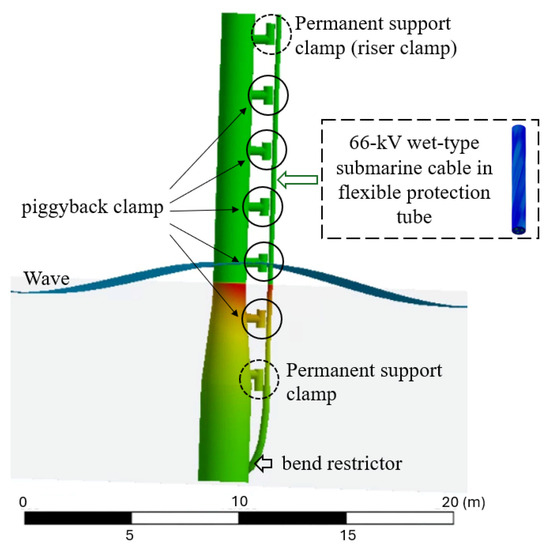
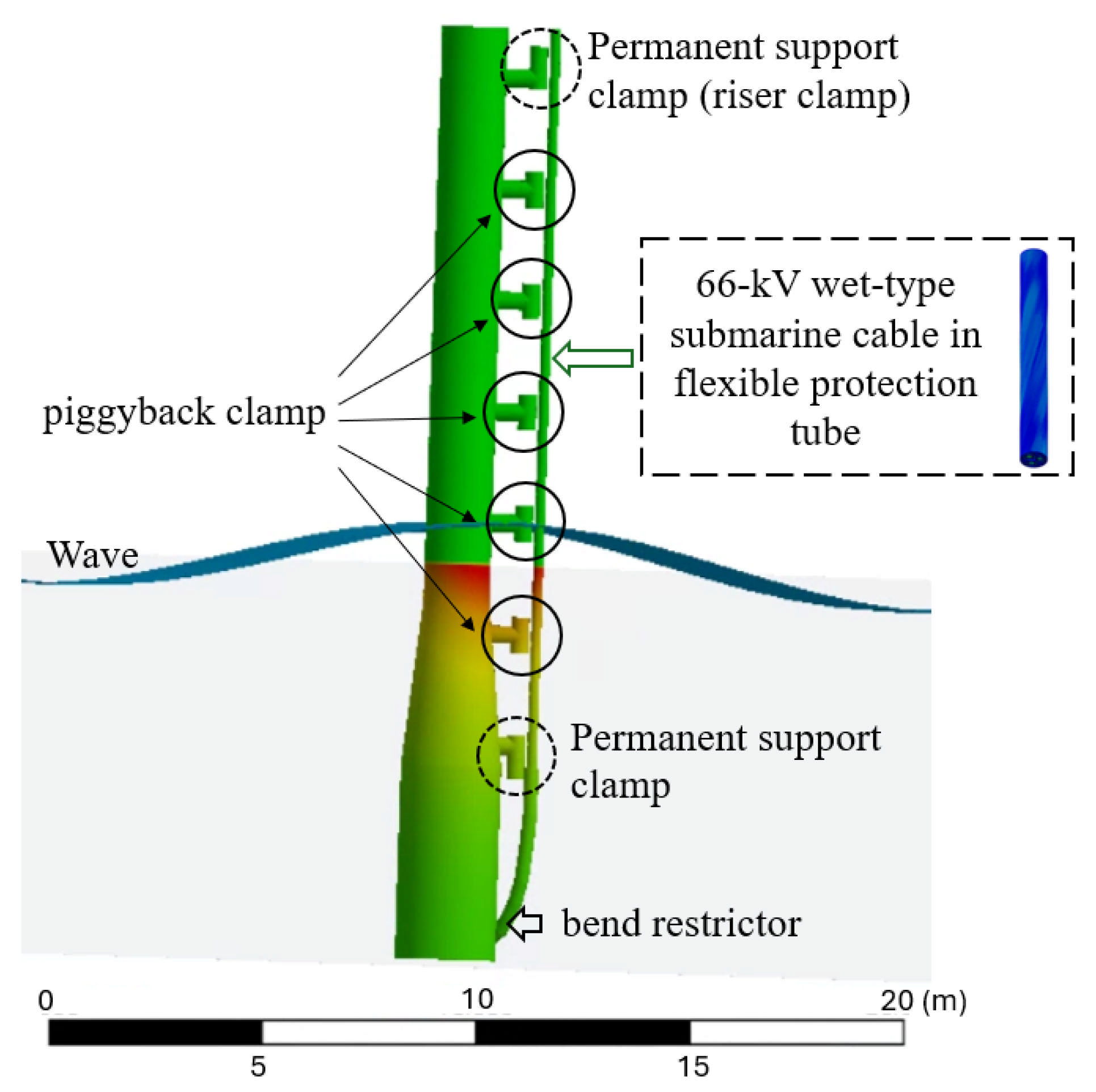
The installation of SPCs in offshore wind farms has traditionally relied on the J-tube method. The FPIS was developed as an alternative solution to overcome the limitations of this conventional approach. In the conventional J-tube approach, cables are pulled through rigid metallic conduits that provide mechanical protection during installation. However, this method has several inherent drawbacks, including restricted heat dissipation for cable sections exposed to air, accelerated material degradation due to repetitive thermal cycling, and potential deterioration of long-term cable performance [28,29]. To address these limitations, the FPIS eliminates the rigid metallic conduit and installs the SPC in a vertically suspended configuration. In this system, the cable is enclosed within a high-density polyurethane flexible protection tube and mechanically supported by a series of distributed clamps along its length. As shown in Figure 1, the FPIS configuration effectively suppressed excessive vibrations, mitigated localized compressive forces, and enhanced heat dissipation to the surrounding environment. Another advantage of the FPIS is its modular design, which facilitates inspection, maintenance, and repair. Localized damage can be addressed by replacing individual components without removing the entire cable assembly. A typical FPIS configuration consists of a flexible protection tube, modular bend restrictor, and two types of clamps: riser clamps and piggyback clamps. The spacing and arrangement of the piggyback clamps were designed in accordance with established DNV guidelines to ensure adequate mechanical support and fatigue performance under dynamic loading conditions [30]. In the present study, particular attention was focused on the cable segment located between adjacent piggyback clamps as this region is expected to experience the most pronounced dynamic response and is therefore critical for fatigue assessment.
Figure 1.
Schematics of the flexible pull-in installation system.
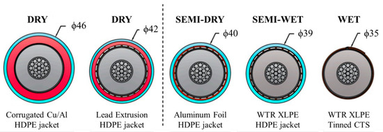
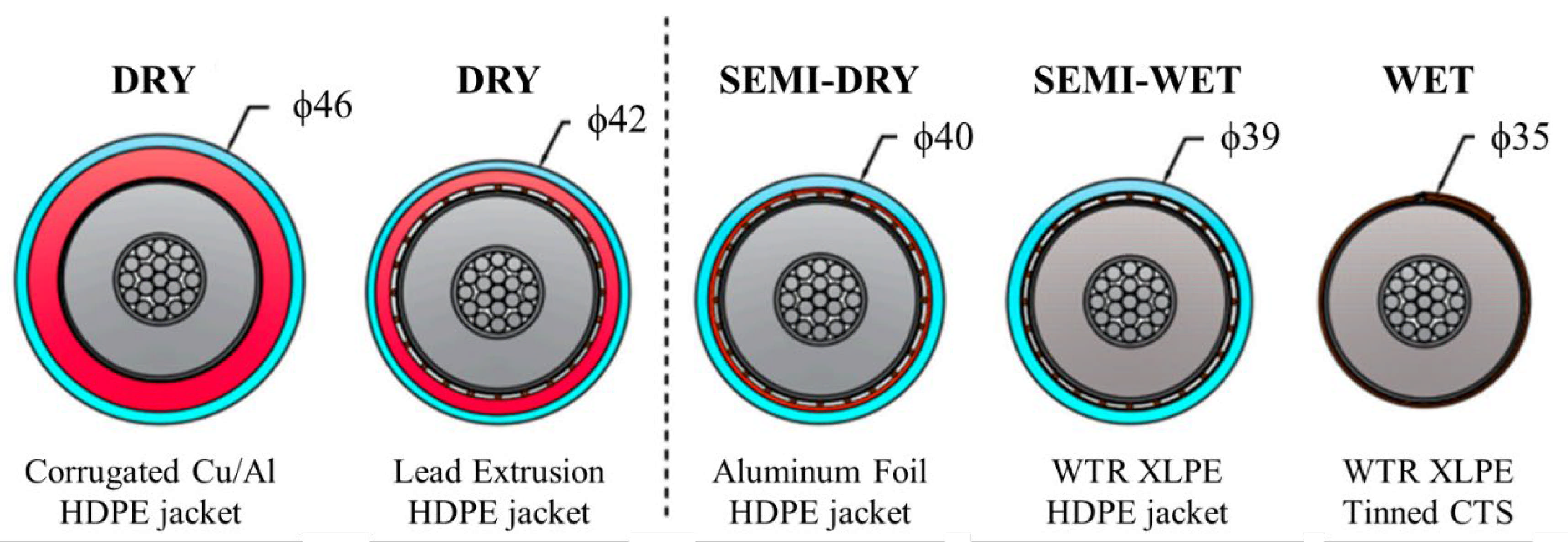
From a structural perspective, SPCs consist of multiple functional layers designed to satisfy both electrical and mechanical requirements in marine environments. The conductor, typically manufactured from copper or aluminum, may be constructed as a solid core or multiwire strands that consist of round or profiled wires, contributing to the axial stiffness and current-carrying capability of the cable. The conductor is surrounded by the insulation system, which generally comprises three co-extruded layers: an inner semiconductive conductor screen, a main insulating layer, and an outer semiconductive insulation screen. These layers play a critical role in homogenizing the electric field distribution to ensure long-term electrical reliability. Based on the configuration of the insulation system and strategy for water-ingress protection, SPCs are commonly classified into dry- and wet-type designs, as shown in Figure 2 [9]. This classification is particularly important for dynamic applications, such as floating offshore wind systems, where cables are subjected to combined mechanical, thermal, and environmental loading. Dry-type SPCs are designed to prevent water penetration into the insulation system throughout their service life. This is typically achieved by incorporating continuous radial and longitudinal water barriers, such as metallic sheaths or laminated aluminum–polymer tapes, which effectively block both radial and axial water migration, even in the presence of local damage to the outer layers. In contrast, wet-type SPCs are designed to allow controlled water ingress into the insulation system, provided that the insulation material itself can tolerate moisture without the significant degradation of electrical performance. In wet-type designs, the insulation—most commonly based on cross-linked polyethylene (XLPE)—is directly exposed to seawater, and no continuous radial metallic water barrier is employed. Instead, water resistance is ensured through appropriate material selection, sufficient insulation thickness, and conservative electrical stress management. Owing to the absence of rigid metallic barriers, wet-type cables exhibit reduced bending stiffness and enhanced flexibility, making them particularly suited for dynamic installations such as FPIS-configured floating offshore wind systems. The 66 kV wet-type SPC in the present study consists of three cores, each comprising metallic layers, including the conductor, associated metallic components, and multiple polyethylene (PE)-based layers. To mitigate the water-treeing phenomena induced by moisture ingress, a tree-retardant XLPE insulation layer was employed. A single layer of yarn and external steel-wire reinforcement was arranged around the cable to provide mechanical protection and structural integrity under tensile and cyclic loading conditions.
Figure 2.
Classification and design configurations of dry- and wet-type submarine cables [9].
2.2. Fundamentals of Fatigue Analysis for Submarine Cables
A 66 kV SPC consists of a combination of polymeric and metallic constituents [31]. The polymer-based components, including PE semiconducting screens, insulation layers, corrosion protection layers, shaped fillers, and yarn elements, are characterized by relatively low elastic moduli and high Poisson’s ratios. Owing to these material properties, polymeric layers generally exhibit limited sensitivity to fatigue damage under cyclic loading. Metallic components, including the electrical conductor, metallic sheath, and steel-wire armor, are inherently more vulnerable to fatigue damage. Accordingly, these elements demand specific and rigorous fatigue evaluation.
In the present study, the fatigue evaluation of metallic components was conducted using a stress-based fatigue assessment framework based on S–N curves. The S–N approach is commonly used in fatigue evaluation. It relates the amplitude of cyclic stress to the number of load cycles required for failure, and is widely adopted for high-cycle fatigue problems, where material behavior remains predominantly elastic. This methodology is particularly suitable for fatigue scenarios involving large numbers of loading cycles, typically exceeding 103–104 cycles, which are representative of long-term operational conditions for SPCs. To quantify fatigue damage under cyclic loading, Miner’s linear cumulative damage rule was employed. This rule evaluates fatigue damage using a cycle ratio. Specifically, it compares the number of imposed stress cycles at a certain stress amplitude with the total number of cycles to failure associated with that amplitude [32]. Fatigue failure is assumed to occur when the accumulated damage reaches or exceeds a critical value of unity. SPCs deployed in offshore environments are subjected to highly complex loading conditions arising from combined wave, current, and platform-induced motions. Environmental forces do not generate perfectly periodic stress cycles. Instead, they create time-dependent and irregular stress histories, which result in variable-amplitude fatigue loading conditions. To systematically characterize such variable loading spectra, the rainflow cycle-counting method was adopted. In this approach, stress–time histories are transformed into equivalent stress cycles through a cycle extraction process, enabling the accurate estimation of fatigue damage contributions from irregular loading sequences. Therefore, the present study performs fatigue evaluation based on irregular displacement time-series data derived from marine environmental loading. Since the fatigue loads consist of variable-amplitude cycles involving both tension and compression, the rainflow counting method was applied to determine the maximum and minimum stress for each cycle. Subsequently, a stress–life (S–N) approach combined with Miner’s rule was employed to evaluate the cumulative fatigue damage.
3. Numerical Methodology
A numerical investigation was conducted to evaluate the fatigue behavior of an SPC installed using an FPIS at the Southwest Offshore Wind Farm in Korea. In this study, a total of 120 ultimate limit state (ULS) load cases were adopted to represent the most severe metocean conditions at the installation site. These load cases were used to evaluate the relative fatigue performance of the cable under critical loading scenarios. A numerical framework was established to assess both the structural response and the associated fatigue behavior of the cable under ULS conditions. The input parameters for the analysis, including the environmental loads, cable configuration, and material properties, were defined based on the project-specific basis of analysis.
3.1. Fatigue Analysis Methodology
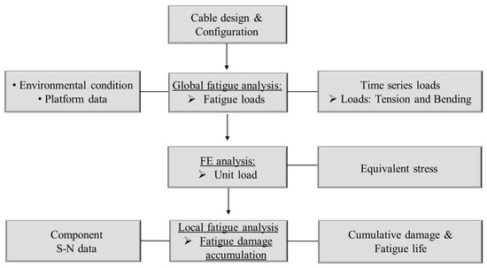
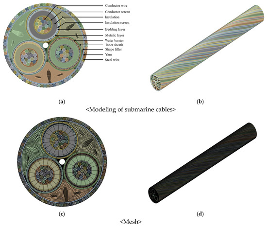
Figure 3 presents an overview of the fatigue analysis procedure used in this study. The methodology consists of two sequential stages: global dynamic analysis and detailed local structural analysis. Fatigue evaluation requires three primary inputs: (i) time-dependent load and displacement histories corresponding to ULS conditions, (ii) stress responses obtained from static finite element (FE) analysis, and (iii) material fatigue properties of individual cable components [33,34].
Figure 3.
Overview of the global–local fatigue analysis procedure adopted in this study.
To obtain the time-series load and displacement data, a global dynamic analysis of the submarine power cable (SPC) integrated within the FPIS configuration was performed. This analysis captured the dynamic response of the cable under severe environmental loads corresponding to ULS conditions. Critical loading scenarios were identified from the global analysis results, and peak responses were detected at a structurally sensitive zone located roughly 1.55 m along the cable. This area corresponded to the location where wave-induced loading effects were most dominant.
Based on the global response results, a local fatigue analysis was subsequently performed. To characterize stress variations within each cable component, a static FE model was applied under representative load cases. The computed equivalent stresses were then coupled with the displacement time-series data derived from the global analysis. The stress responses obtained from the analysis were mapped onto the S–N curves corresponding to the metallic components of the cable to estimate fatigue damage. For the local structural assessment, the same material properties used in the static FE simulation were employed. Particular emphasis was placed on fatigue-governing elements such as the conductor and steel-wire armor. The considered properties included elastic constants, yield and ultimate tensile strengths, and fatigue S–N characteristics [33]. Based on these input parameters, the cumulative fatigue damage for each component was calculated in accordance with recognized fatigue life prediction methodologies [33]. The resulting fatigue performance was assessed against the required design life criteria. The submarine cable fatigue analysis was implemented through FEM using ANSYS Mechanical and ANSYS nCode DesignLife [34] (version 14.0). Separately, global dynamic simulations were performed in OrcaFlex 11.4 (Orcina Ltd., Ulverston, UK), an industry-standard tool, to extract time-dependent load and displacement histories corresponding to FLS conditions.
3.2. Numerical Modeling
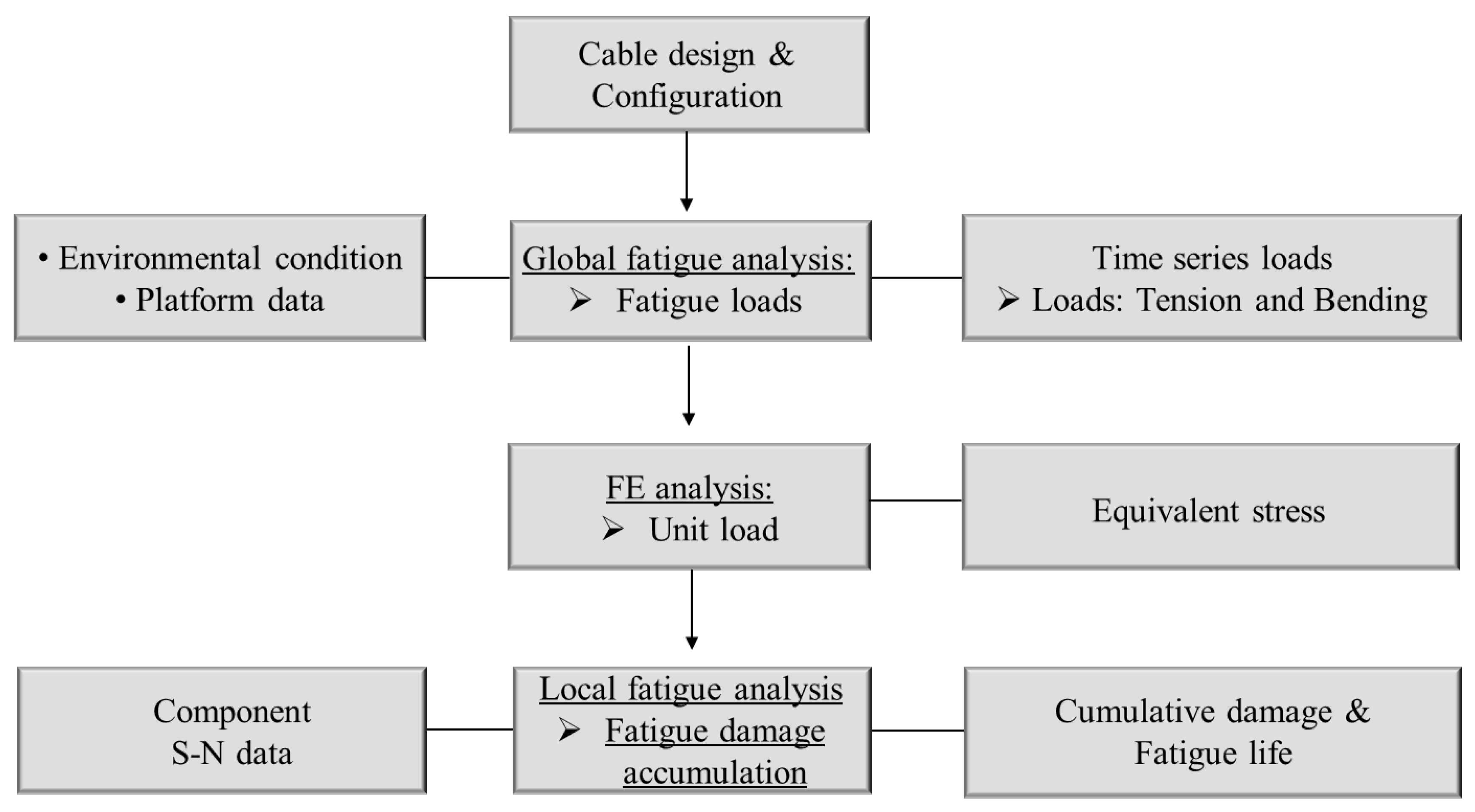
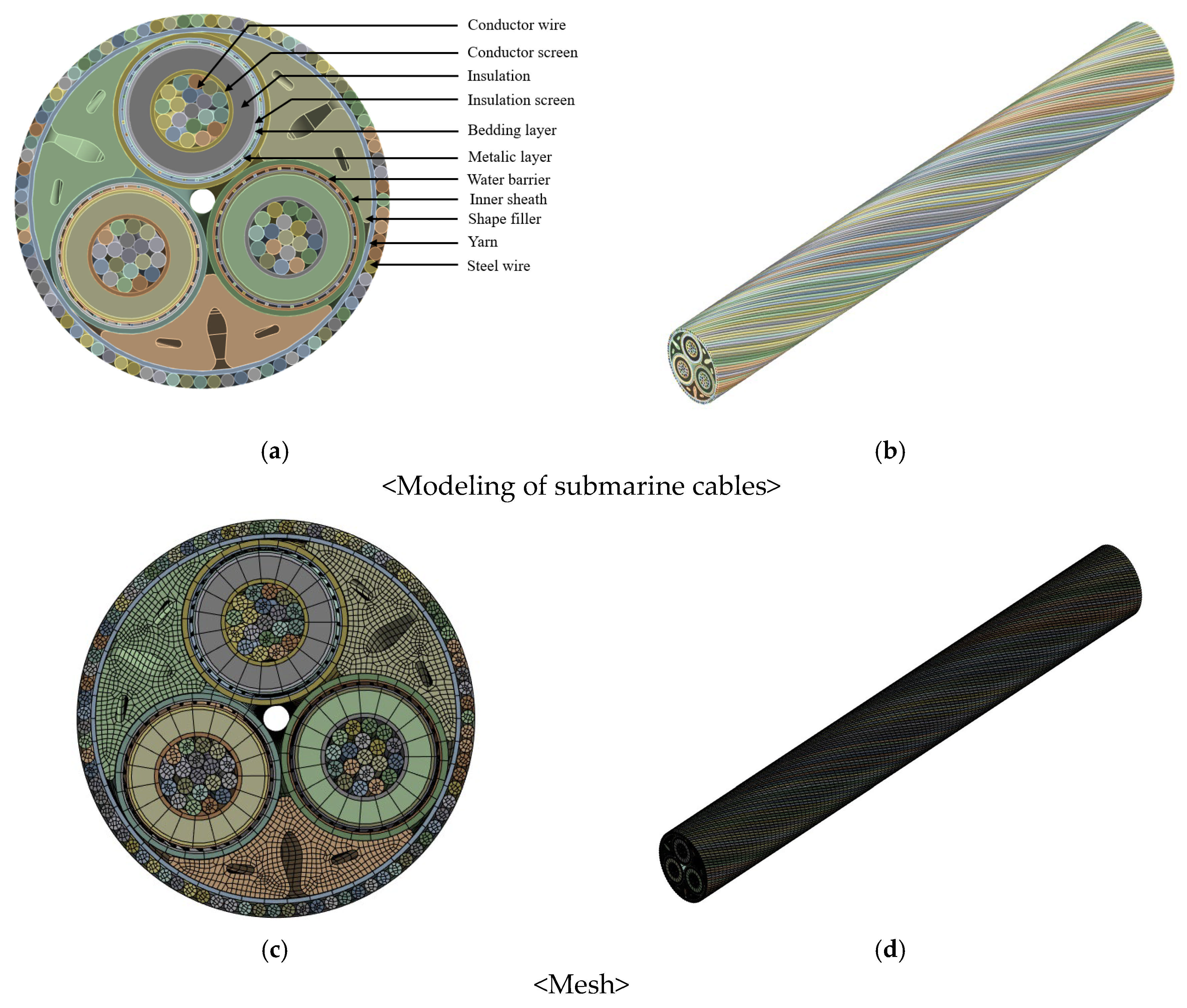
A numerical representation of the 66 kV wet-type submarine power cable was constructed. Figure 4 depicts the three-dimensional FE model, which corresponds to a cable segment measuring 0.173 m in outer diameter and 1.55 m in length. The internal structure of the cable consists of 11 concentric layers, reflecting the actual cable construction. The metallic components include the conductor, metallic layer, water barrier, and steel-wire armor, while the nonmetallic components include the semiconductive screen, insulation, bedding, inner sheath, shaped filler, and yarn. Except for the yarn layer, most components were arranged in a helical configuration. In particular, the steel-wire armor and conductor were modeled with helical pitch geometries corresponding to helix angles of 19.24° and 6.62°, respectively, to accurately capture their mechanical behaviors under tensile loading. Mesh discretization was performed using a sweep method [35], producing structured hexahedral elements throughout the model. This approach ensures the numerical stability and accuracy for stress and deformation evaluation in multilayer cable structures.
Figure 4.
Three-dimensional FE representation of the 66 kV wet-type submarine cable, showing (a,c) the plan view and (b,d) the side view.
Regarding mesh independency, a mesh convergence study was performed by progressively reducing the element size. The finite element models were categorized into coarse, medium, and fine meshes, with an incremental difference of approximately 40,000 elements between each refinement level, as summarized in Table 1. The variation in the maximum equivalent stress between the medium and fine meshes converged to within 0.17%, confirming mesh independence. Considering both accuracy and computational efficiency, the final finite element model consisted of approximately 2,671,582 nodes and 542,440 elements. Of these, the steel-wire armor region accounted for 2,549,754 nodes and 525,520 elements.
Table 1.
The mesh sensitivity results.
The material properties used in the numerical analysis were identical to those of the 66 kV wet-type SPC employed in the experimental tensile tests. The material properties used in the numerical analysis were identical to those of the 66 kV wet-type SPC employed in the experimental tensile tests. These properties were experimentally obtained from the 66 kV wet-type SPC specimens used in this study and were provided by the cable manufacturer, Taihan Cable & Solution Co., Ltd., Seoul, Republic of Korea. Table 2 provides an overview of the material characteristics used in the study. These include the density, elastic modulus, and Poisson’s ratio for the respective cable components.
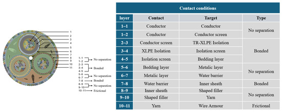
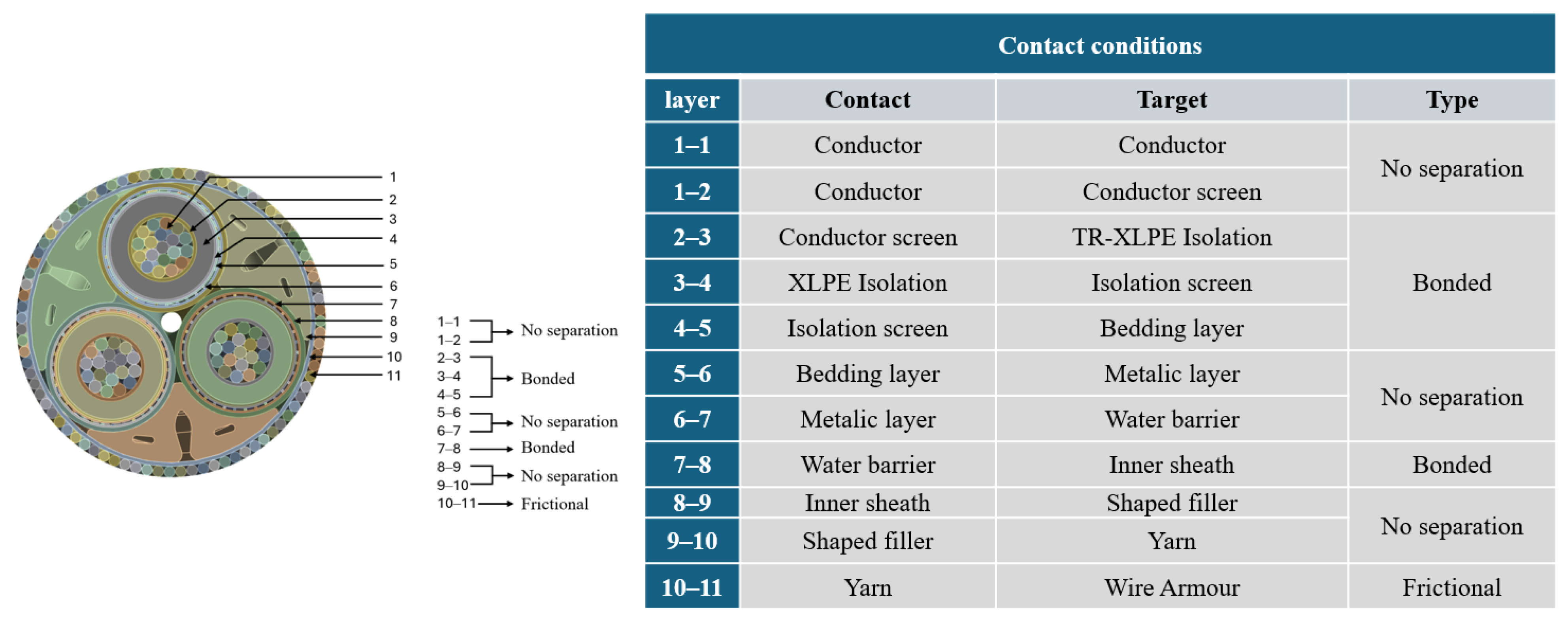
Owing to its multilayered construction, the 66 kV wet-type SPC exhibited distinct contact behaviors between adjacent layers. Accordingly, it is essential to explicitly define the contact and target surfaces, and assign the appropriate contact formulations for each interface in the numerical model. In the present analysis, three different contact conditions were considered, as shown in Figure 5. The regions in which the adjacent layers were fully constrained were modeled using a bonded contact condition to prevent any relative displacement.
Figure 5.
Contact conditions applied to the 66 kV wet-type submarine cable.
The assessment of fatigue damage targeted the metallic constituents of the SPC. Particular attention was given to the conductor and the steel-wire armor, which are known to dominate the fatigue behavior under cyclic loading. In contrast, nonmetallic components such as PE and polypropylene typically exhibit high Poisson’s ratios and relatively low elastic moduli, resulting in limited susceptibility to fatigue damage. These polymeric layers were excluded from the fatigue damage evaluation. A stress-based fatigue assessment approach using S–N (stress–life) curves [36,37] was employed to evaluate the fatigue performance of the metallic components. This method is appropriate for high-cycle fatigue conditions, in which the stress levels remain predominantly within the elastic regime. The mechanical properties of the outer sheath are summarized in Table 3. The table also includes the tensile yield strength and ultimate tensile strength of the copper conductor and steel-wire armor. Fatigue S–N data for both the conductor and the steel wire were taken from relevant literature sources [36,37], are listed in Table 4 and used to quantify the fatigue damage under cyclic loading conditions. The S–N data used in the fatigue analysis were obtained from the 66 kV SPC manufacturer, Nexans. The S–N curves correspond to products compliant with the guidelines of Det Norske Veritas (DNV) [38] and were adopted for the present evaluation [36,37].
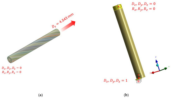
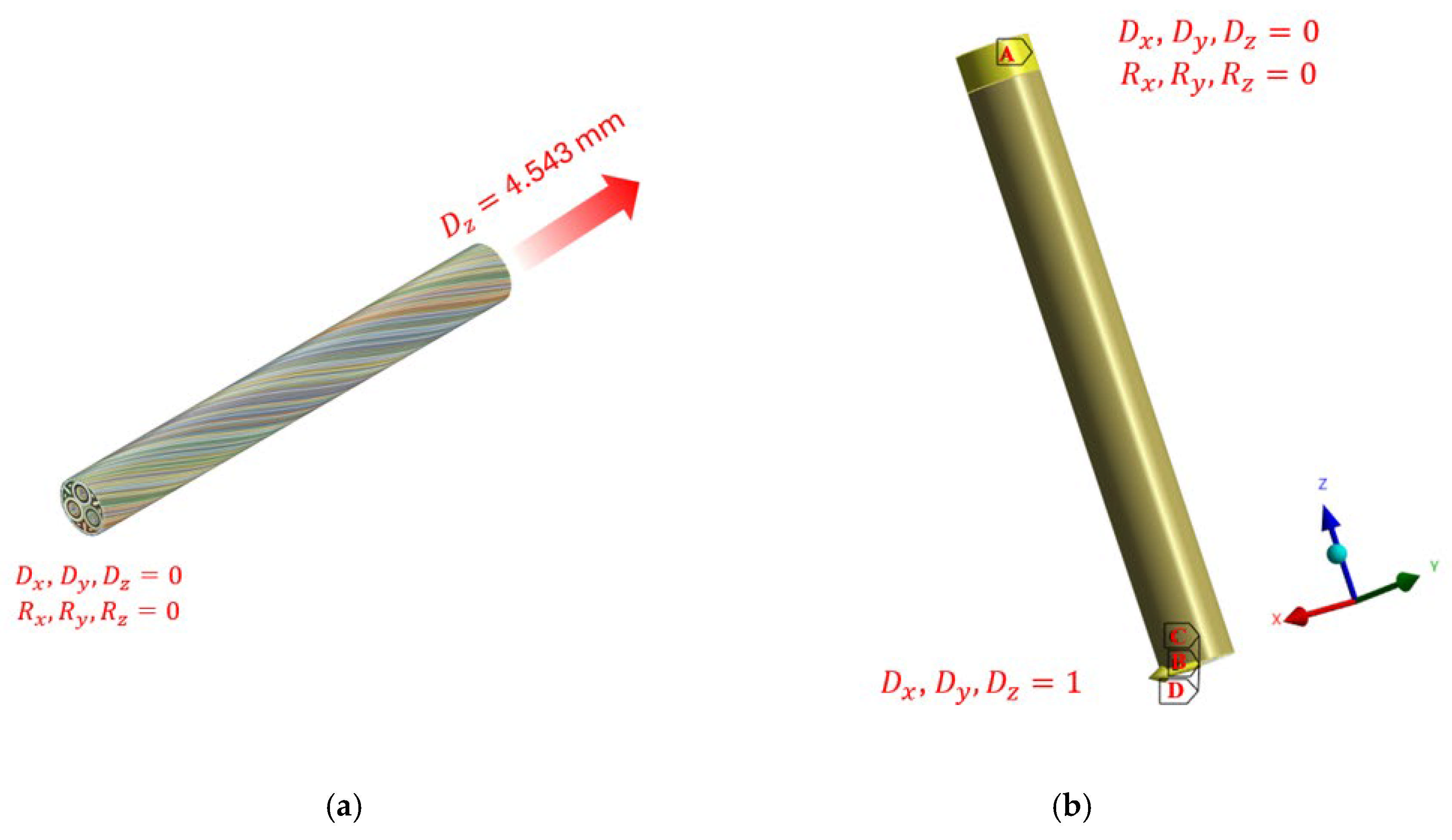
The contact conditions were updated to account for the additional outer sheath layers. The interaction between the steel-wire armor and the first outer sheath layer was modeled using a no-separation contact condition. This setup allowed relative motion in the tangential direction while suppressing normal gap formation. In contrast, a bonded contact condition was assigned between the first and second outer sheath layers (outer sheath (1st)–outer sheath (2nd)), assuming full constraint without relative motion between the two layers. The boundary conditions were determined from the imposed displacement loads. These loading conditions governed the constraint setup in the analysis, as shown in Figure 6. To apply the time-series displacement data for fatigue analysis, displacement amplitudes of 1 mm were imposed in the x-, y-, and z-directions at the lower cross-section of the cable (Point B–D). At point A, which corresponds to the clamp-fixed region, all translational (Dx, Dy, and Dz) and rotational (Rx, Ry, and Rz) degrees of freedom were fully constrained to represent the clamped boundary condition.
Figure 6.
Boundary conditions defined based on the displacement loading conditions ((a): Numerical validation (Tensile test) calculation, (b): Fatigue analysis).
Assigning a friction coefficient to all contact interfaces in the three-dimensional model can lead to excessive computational cost and potential non-convergence issues during the analysis. Moreover, previous studies have reported that the influence of the friction coefficient on the mechanical behavior of submarine cables is negligible [39,40]. Therefore, the wire armor, identified as a primary load-bearing component under external loading in the static analysis, was modeled using a frictional contact condition at its interface with the surrounding yarn layer. A friction coefficient of 0.2 was adopted, corresponding to the interaction between steel and PE materials, based on values reported in the literature [41].
Table 2.
Material properties required for the numerical analysis.
Table 3.
Mechanical properties of the outer sheath and tensile characteristics (yield and ultimate strengths) of the copper conductor and steel-wire armor.
Table 4.
S–N data for the conductor and steel obtained from the literature [36,37].
4. Results and Discussion
4.1. Tensile Test
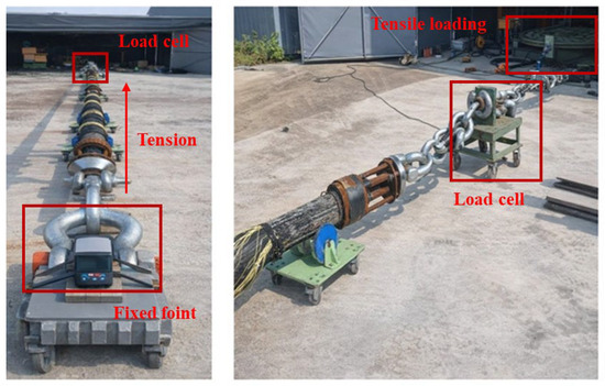
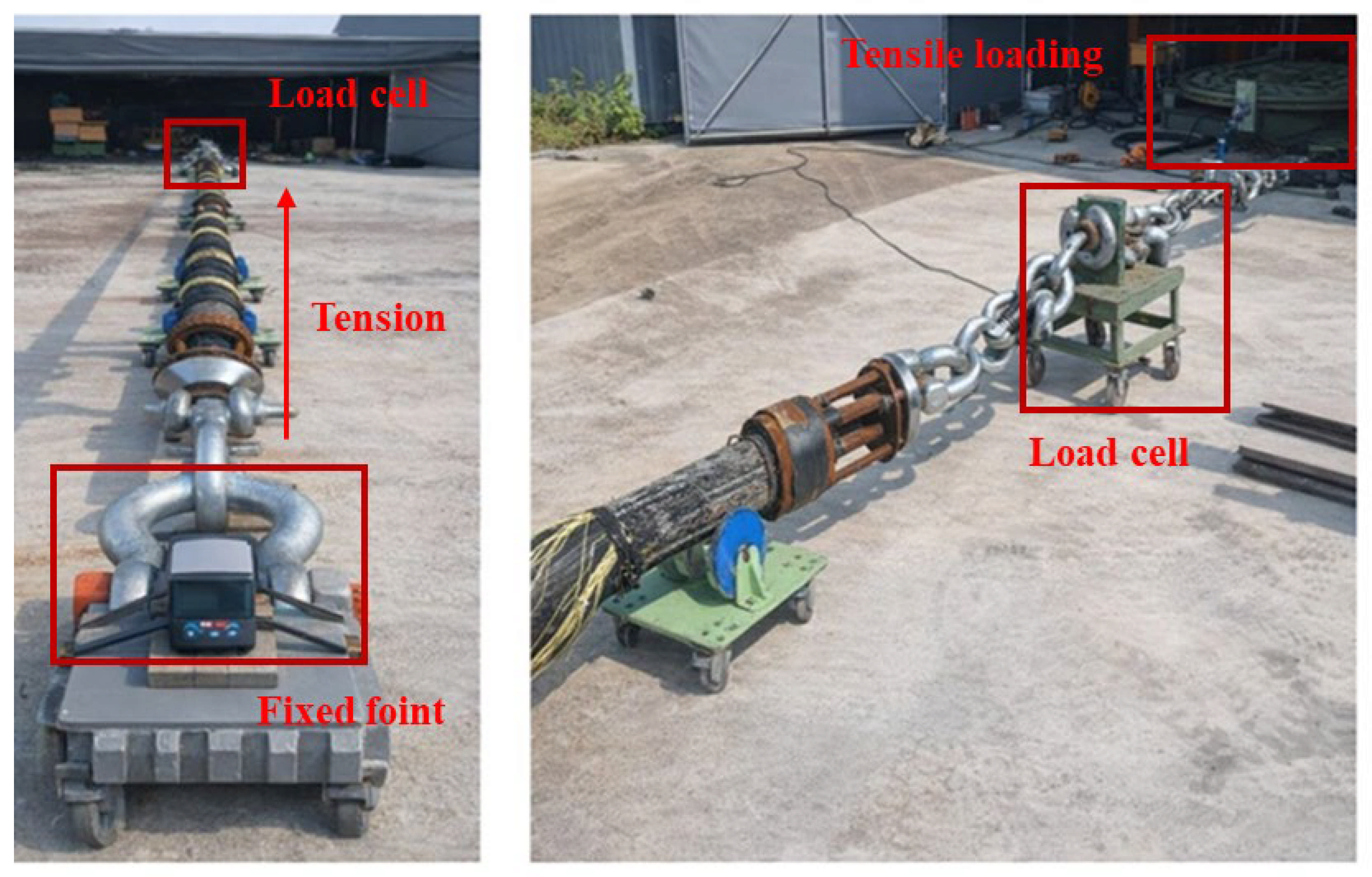
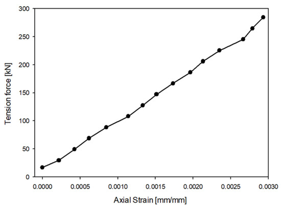
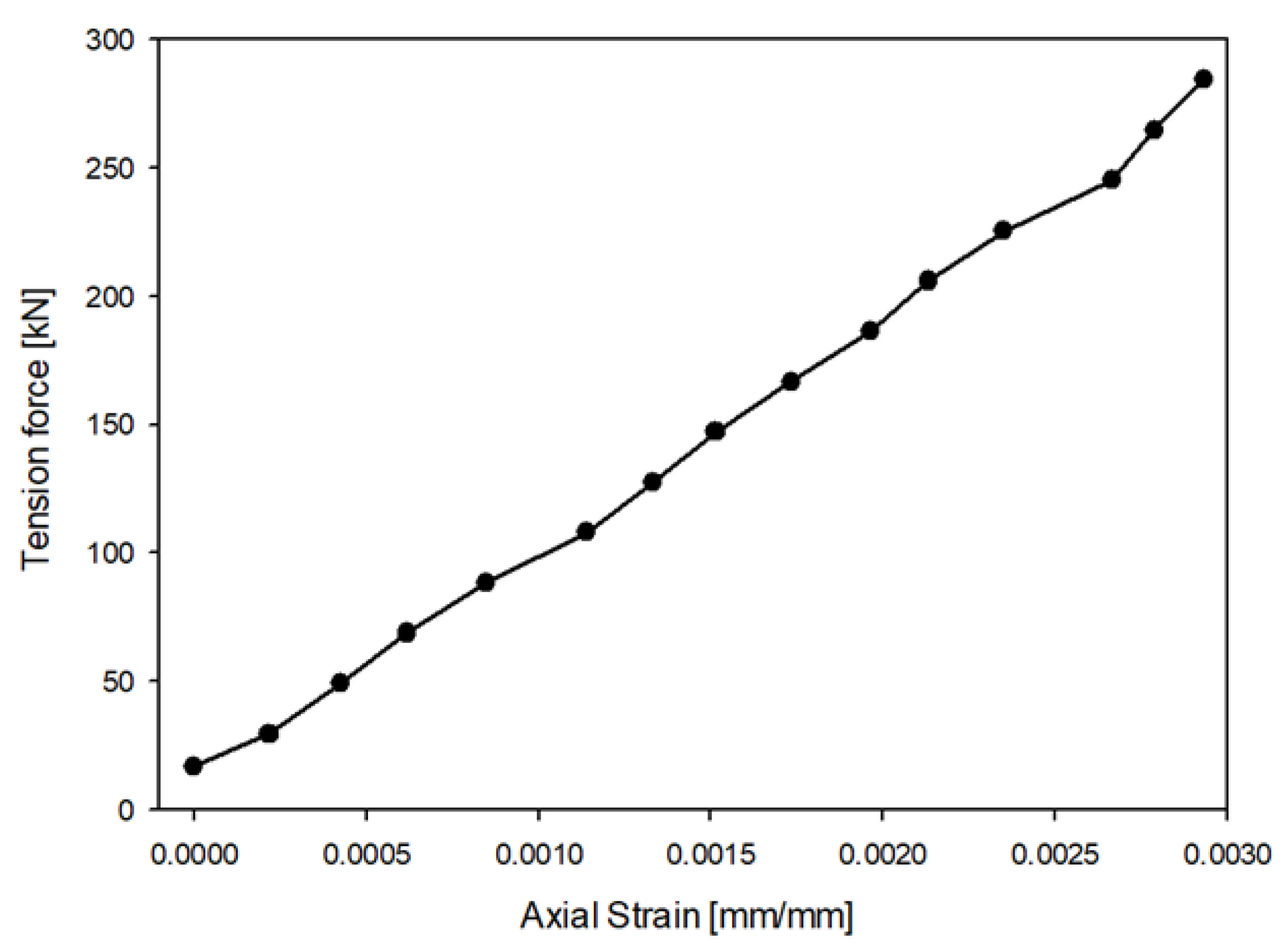
The tensile test procedure and loading conditions were determined according to the CIGRE Technical Brochure TB 623 [43]. A cable specimen with a total length of 8.256 m was prepared for the tensile test. As shown in Figure 7, the specimen was fixed at both ends using specially designed jigs, and tensile loads were applied stepwise using a universal tensile testing machine. The distance between the jig and the support was set to approximately 3619 mm measured from one side, and the load was applied to one end section up to a maximum of 284.4 kN. In order to minimize sagging induced by gravitational loading during the test, supporting fixtures were installed along the specimen length. A dedicated actuator head was fabricated to ensure uniform load application during tensile loading. One end of the specimen was rigidly fixed to establish the boundary condition. The opposite end was allowed rotational movement to prevent the development of unintended bending moments during the test. The tensile test results are presented in Figure 8, which shows the relationship between the applied tensile load and resulting axial deformation of the specimen. Under an applied tensile force of 284.4 kN, a horizontal displacement of approximately 24.2 mm was observed. These results provide essential reference data for validating the numerical model and assessing the axial stiffness characteristics of wet-type SPCs under tensile loading.
Figure 7.
Experimental setup of the tensile test equipment.
Figure 8.
Tensile test results.
4.2. Global Analysis of Time-Series Displacement Behavior
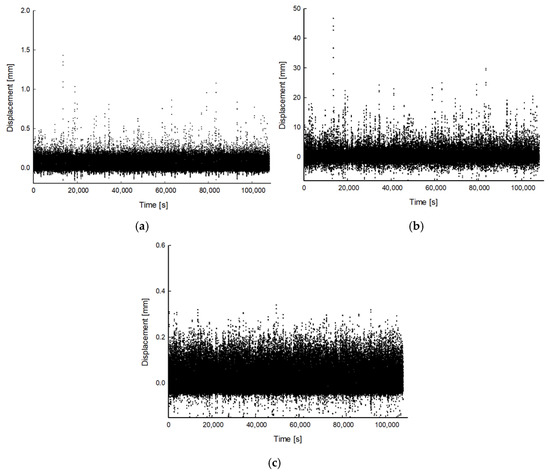
Global dynamic simulation was carried out to characterize the displacement response of the SPC installed in the FPIS arrangement. The analysis was performed under ULS conditions to obtain the corresponding time-series data. The model accounted for the main components of the FPIS. These included the flexible protection tube, bend restrictor, riser clamp, and piggyback clamp assemblies, enabling a realistic simulation of wave-induced environmental loading. A representative configuration of the global analysis model used for the SPC installed with the FPIS is shown in Figure 1. Wind and wave inputs were derived from site-specific measurements at the Southwest Offshore Wind Farm in Korea, where the FPIS installation is scheduled. The ULS analysis employed 50-year return-period metocean conditions for the wind turbine generator and offshore substation, consistent with the recommendations of IEC 61400-3 [36]. Table 5 provides the corresponding environmental input parameters. For a conservative assessment, waves were assumed to propagate perpendicular to the cable installation direction, resulting in the largest wave- and current-driven loads on the SPC and cable protection components. The displacement time-series data were obtained from the cable section between the third and fourth piggyback clamps measured from the FPIS top, as this region experienced the highest wave-induced response. The analysis procedure followed the recommendations of IEC 61400-3 [36], a total of 120 loading cases were generated by varying the significant wave height (0.25–7 m), wave period (0–20 s), and wave direction (315°) under a reference hub-height wind speed of at least 31 m/s at an elevation of 80 m. Each loading condition was simulated for a duration of 3 h. The corresponding displacement time-series data were extracted for the selected 1.55 m cable segment, which is situated within the splash zone and subjected to pronounced free-surface-induced motion. The displacements were evaluated along the three principal axes (x, y, and z) at the structurally critical region, as shown in Figure 9. Among the three principal directions, the lateral (y-axis) displacement amplitude was the greatest, while the vertical (z-axis) response was comparatively minimal. This observation indicates that the structural response is primarily driven by wave-induced lateral excitation, while vertical effects are comparatively limited owing to the vertically suspended configuration of the FPIS.
Table 5.
Environmental loading parameters for the ULS assessment based on 50-year return-period metocean conditions.
Figure 9.
Displacements along the three principal axes (x, y, and z) at the structurally critical region ((a): x-axis, (b): y-axis, (c): z-axis).
4.3. Numerical Validation
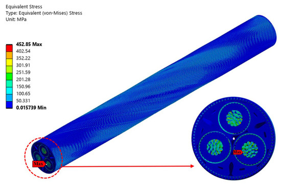
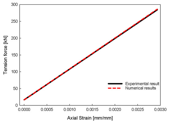
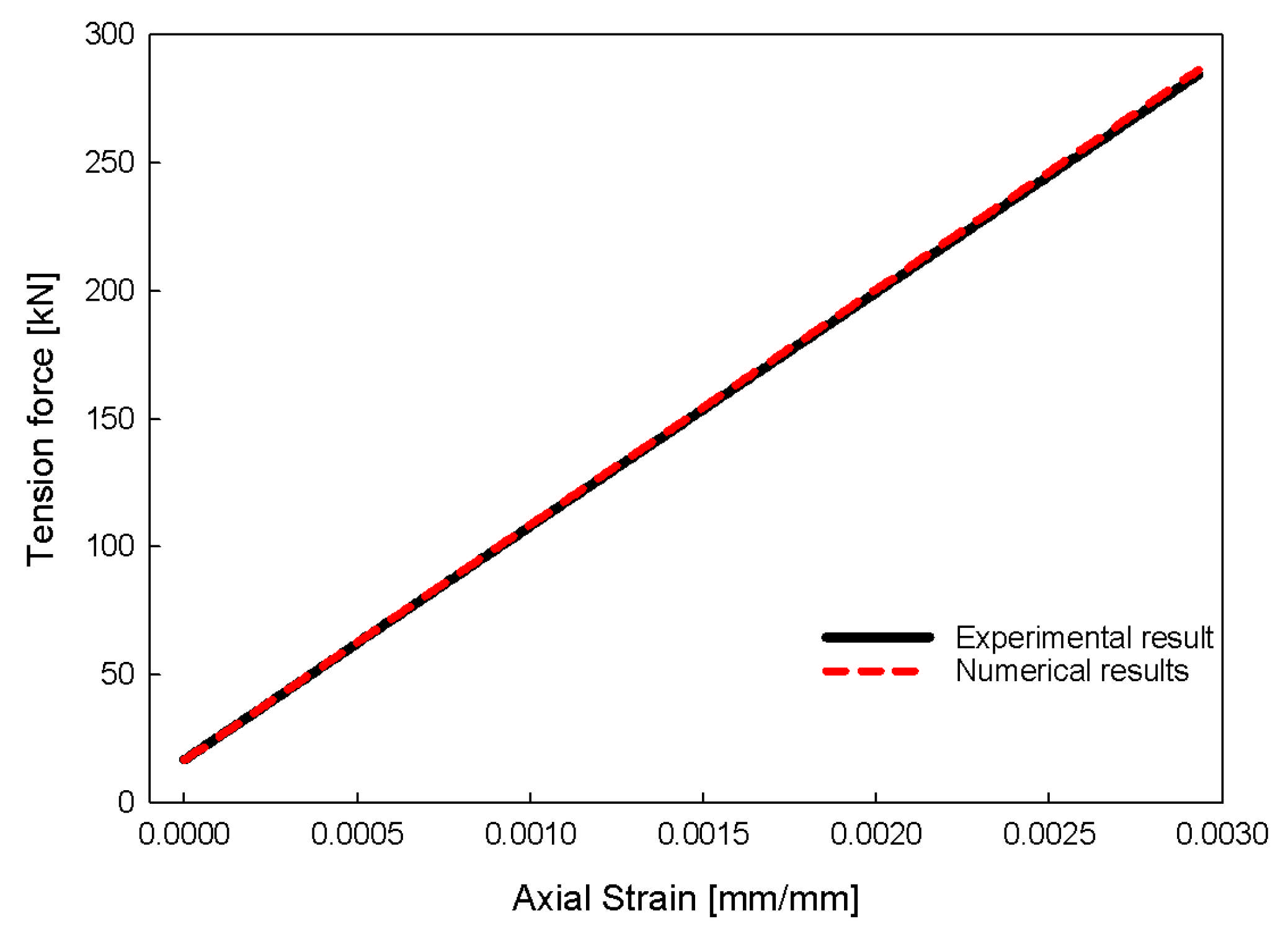
The present analysis was conducted to verify the validity of the numerical methodology based on the tensile test results of the 66 kV wet-type SPC (Section 4.1). The numerical analysis was performed to assess the reliability of the constructed FE model and evaluate its capability to accurately reproduce the mechanical behavior observed in the experiments. Figure 10 shows the distribution of the von Mises stress under tensile loading. The numerical results indicate that relatively high stress levels are concentrated in the metallic components of the cable. In particular, the maximum von Mises stress was observed in the outer conductor wires, reaching approximately 452.85 MPa. This stress distribution was consistent with the expected load-carrying role of the metallic layers under axial tension. A comparison of the experimentally measured and numerically predicted strain–tension force relationships is shown in Figure 11. At a strain level of approximately 0.293%, the tensile force predicted by the numerical analysis was 286.3 kN, which shows a discrepancy of approximately 0.67% compared with the experimental result of 284.4 kN. This close agreement demonstrates that the proposed numerical model accurately captures the axial stiffness and deformation characteristics of the wet-type SPC. Based on this validation, the developed numerical modeling approach is considered reliable for subsequent fatigue analyses of the 66 kV wet-type SPC installed using the FPIS. These results were intended to validate the reliability of the numerical model based on the mechanical response, with the primary objective of comparing the predicted mechanical behavior—considering material properties, contact conditions, and loading configurations—with the measured experimental results. However, this validation approach has inherent limitations in fully capturing the complex interlayer friction and bending stress behavior of the cable. Therefore, additional experimental verification through cyclic bending tests is required in future studies to further enhance the credibility of the numerical framework.
Figure 10.
Von Mises stress distribution under tensile loading.
Figure 11.
Comparison between the experimental and numerical results for the strain–tensile force relationship.
4.4. Static Finite Element (FE) and Fatigue Analysis
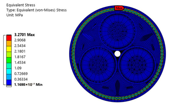
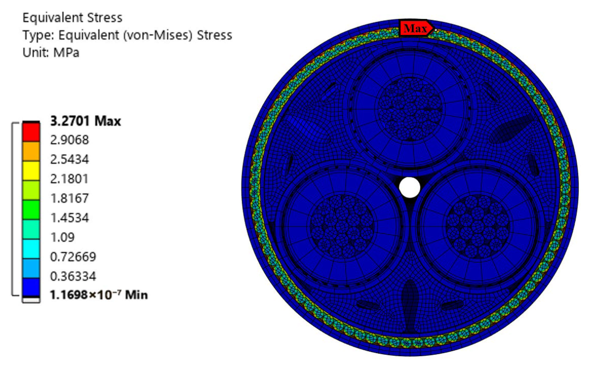
The numerical model used for the fatigue analysis of the 66 kV wet-type SPC is shown in Figure 4, where two additional layers forming the outer sheath are included at the outermost region of the cable. With the inclusion of the outer sheath, the overall cable diameter increased to approximately 0.181 m. An FE mesh was generated using the same sweep-meshing method [35], resulting in a structured hexahedral mesh. The model consisted of 2,671,582 nodes and 542,440 elements. The equivalent stress contours obtained from the static FE simulation are shown in Figure 12 for the 66 kV wet-type SPC installed within the FPIS. A displacement of 1 mm was applied in each principal direction (x, y, and z) to evaluate the stress response. The maximum stress value, about 3.27 MPa, was identified in the upper section of the steel-wire armor. This behavior is reasonable because the steel wires, having the largest elastic modulus among the cable layers, primarily resist the applied mechanical loading. The equivalent stress results were combined with the fatigue displacement time-history data (Figure 9) and the S–N curves of the metallic cable components, following the analysis procedure illustrated in Figure 3, to derive the local fatigue assessment results.
Figure 12.
Distribution of equivalent stress as predicted by the static finite element simulation for the 66 kV wet-type submarine cable.
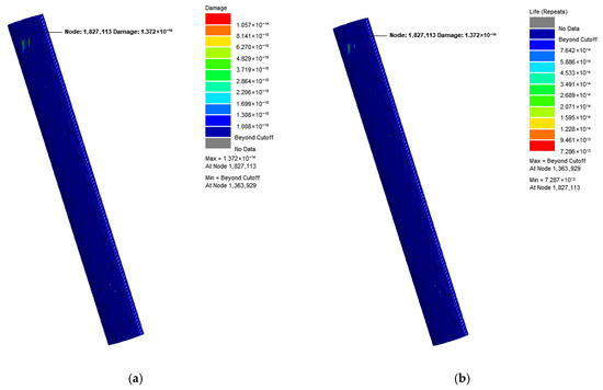
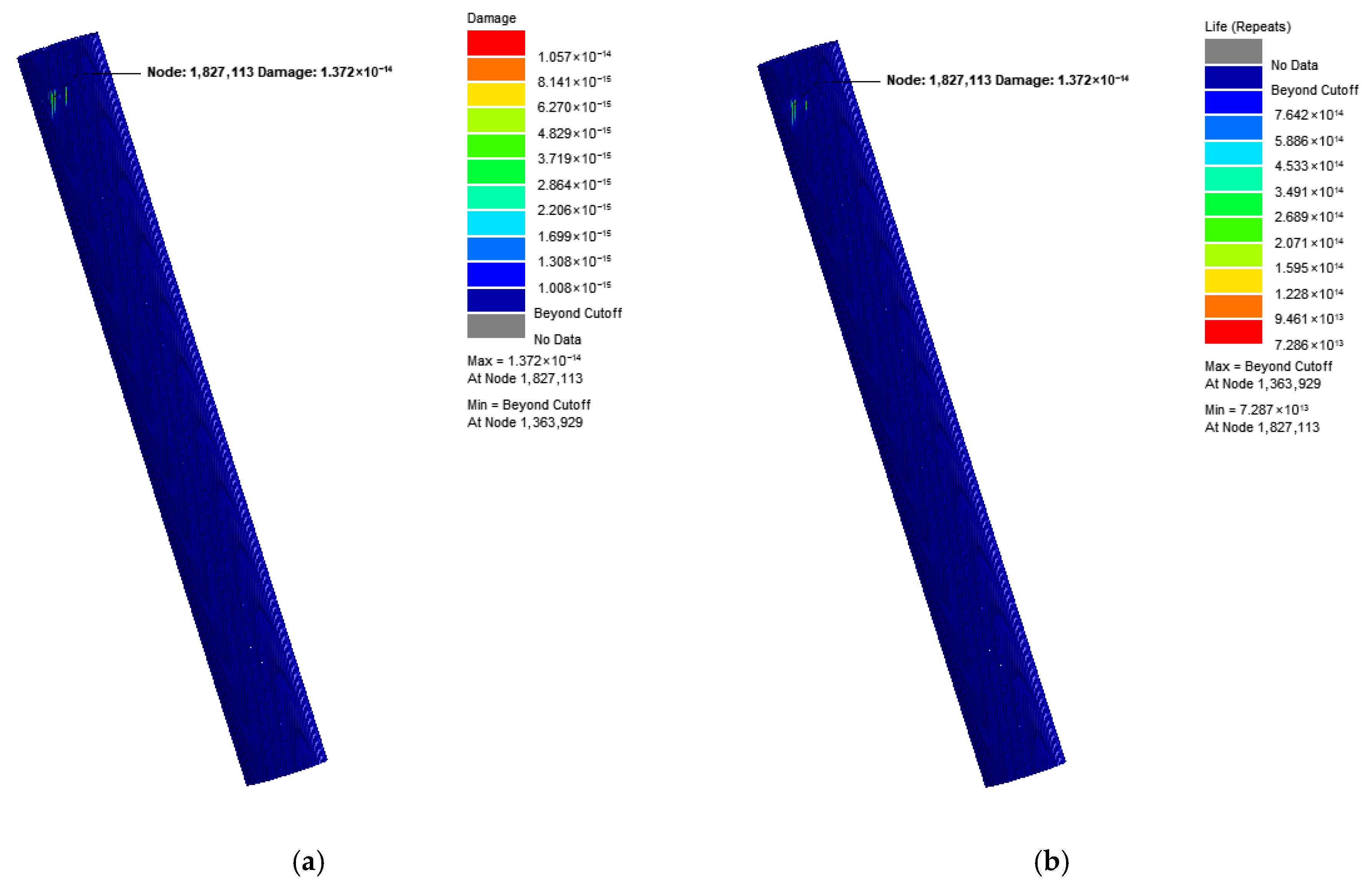
The fatigue characteristics of the 66 kV wet-type SPC were investigated in this study. Particular attention was directed toward the metallic components that sustain mechanical loads, such as the conductor, metallic sheath, and steel-wire armor. Fatigue assessments were performed under 120 displacement-based time-history loading cases derived from the global dynamic response. The most critical loading case was identified among the analyzed scenarios. In this condition, displacement values ranged from −0.4151 to 1.429 mm in the x-direction, −8.838 to 46.67 mm in the y-direction, and −0.3808 to 0.3399 mm in the z-direction. The fatigue life distribution is shown in Figure 13. The shortest fatigue life was observed in the steel-wire armor close to the fixed boundary. In this region, the predicted fatigue life was 8.71 × 10⁴ cycles. At the same location, the cumulative fatigue damage was evaluated as 1.15 × 10⁻⁵, as presented in Figure 13. Compared with the conductor and metallic sheath, the steel-wire armor exhibited a noticeably lower fatigue resistance, primarily because of its higher stress concentration and sensitivity to cyclic bending near the constrained region. Based on these findings, the steel-wire armor was found to be the most fatigue-sensitive element. It therefore governs the fatigue performance of the wet-type submarine cable under the investigated loading conditions.
Figure 13.
Fatigue analysis results: (a) cumulative damage and (b) fatigue life cycles.
4.5. Fatigue Life Evaluation According to the Helix Angle of Wire Armor
To accommodate repeated bending and axial tensile loads, most structural components of a 66 kV wet-type SPC are arranged in helical configurations to enhance the overall flexibility [39]. Because of this helical architecture, the mechanical and electrical characteristics of SPCs are strongly dependent on the geometric parameters of each component. Consequently, an accurate understanding of the mechanical behavior associated with the helix geometry of the wire armor, which is one of the primary load-bearing components, is essential for reliable cable design. Previous studies have investigated the influence of the helix angle on the mechanical response of SPCs, including stiffness, stress distribution, and load transfer characteristics [44,45], as well as its impact on electrical performance, such as current-carrying capacity and electromagnetic behavior [45,46]. For steel-wire armor, electrical losses along the cable length are generally calculated in accordance with the IEC 60287 standard [47]. However, the IEC 60287 formulation assumes the armor to be a continuous cylindrical layer rather than a helical assembly of multiple steel wires, and therefore does not account for mechanical losses or the interaction effects arising from pitch length variations [48]. Fang [44] investigated the influence of pitch length on bending behavior by arbitrarily adjusting the lay length of the steel-wire armor. In addition, Benato et al. [45] and Giussani et al. [46] analyzed the effect of pitch length on power losses by varying the armor lay length within the ranges of 1–3 m and 2.1–6 m, respectively. Overall, most previous studies have focused on evaluating the influence of pitch length in industrial submarine cables [45,46]. However, despite these efforts, quantitative assessments of how variations in the helix angle affect fatigue behavior remain limited, particularly for wet-type SPCs subjected to cyclic loading in dynamic installation systems.
In this section, the fatigue performance of the steel-wire armor, the most fatigue-critical component, is systematically evaluated as a function of the helix angle. As summarized in Table 6, the helix angle was varied by adjusting the pitch length to 1/3, 1/2, 2, and 4 times that of the reference configuration. For each case, the fatigue life was assessed to quantify the sensitivity of fatigue damage accumulation to changes in helix geometry. This parametric investigation aims to clarify the role of the wire-armor helix angle in governing fatigue endurance and to provide design-oriented insights for optimizing wet-type SPCs employed in flexible pull-in installation systems.
Table 6.
Variation in the helix angle with respect to the pitch length.
Effect of Wire-Armor Helix Angle
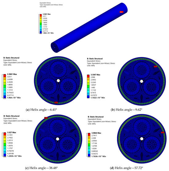
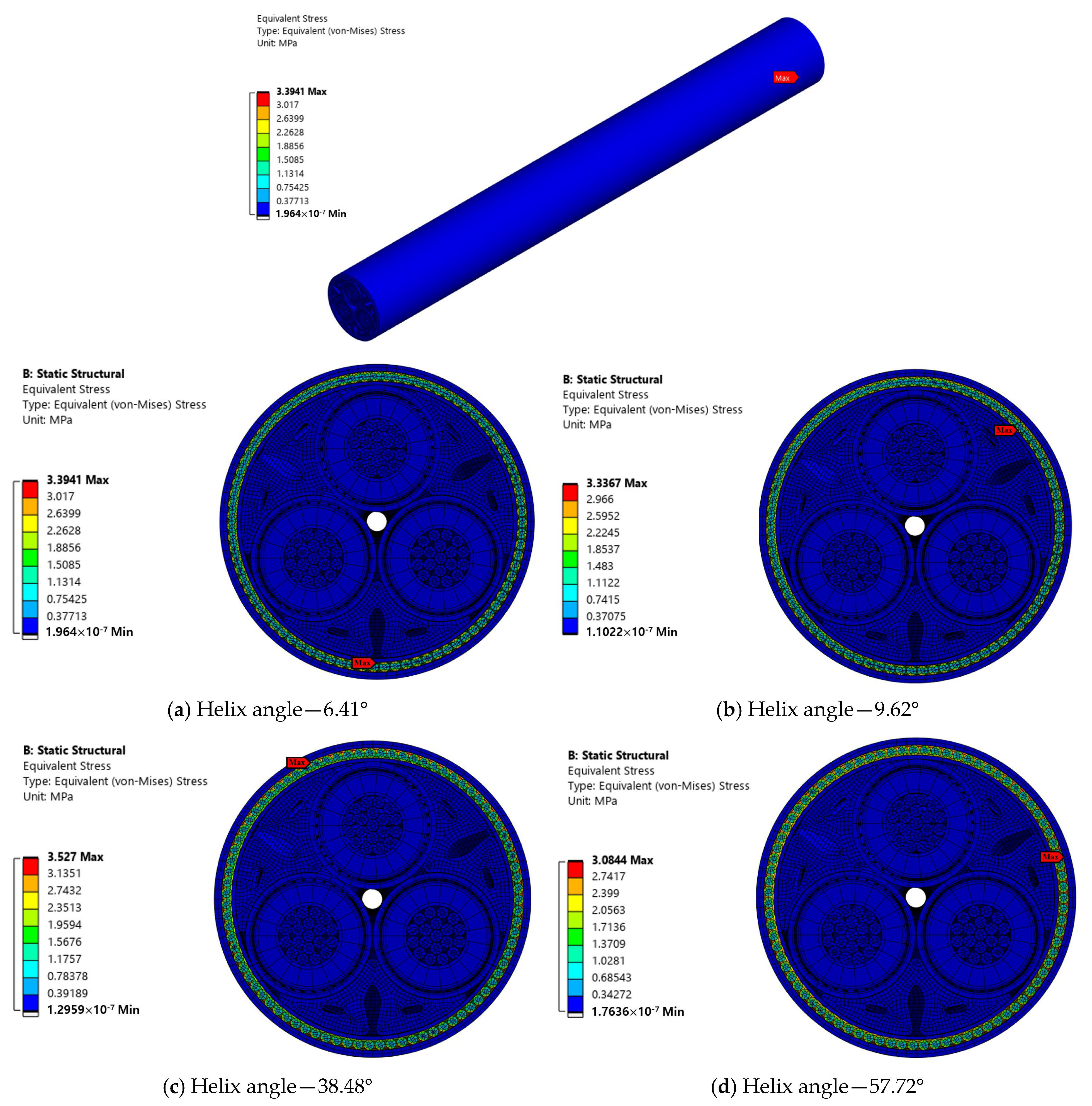
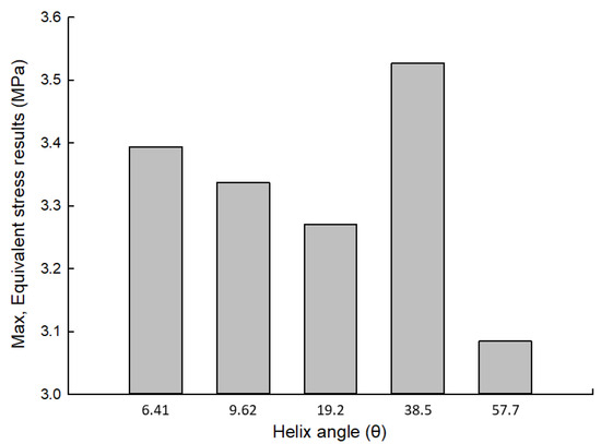
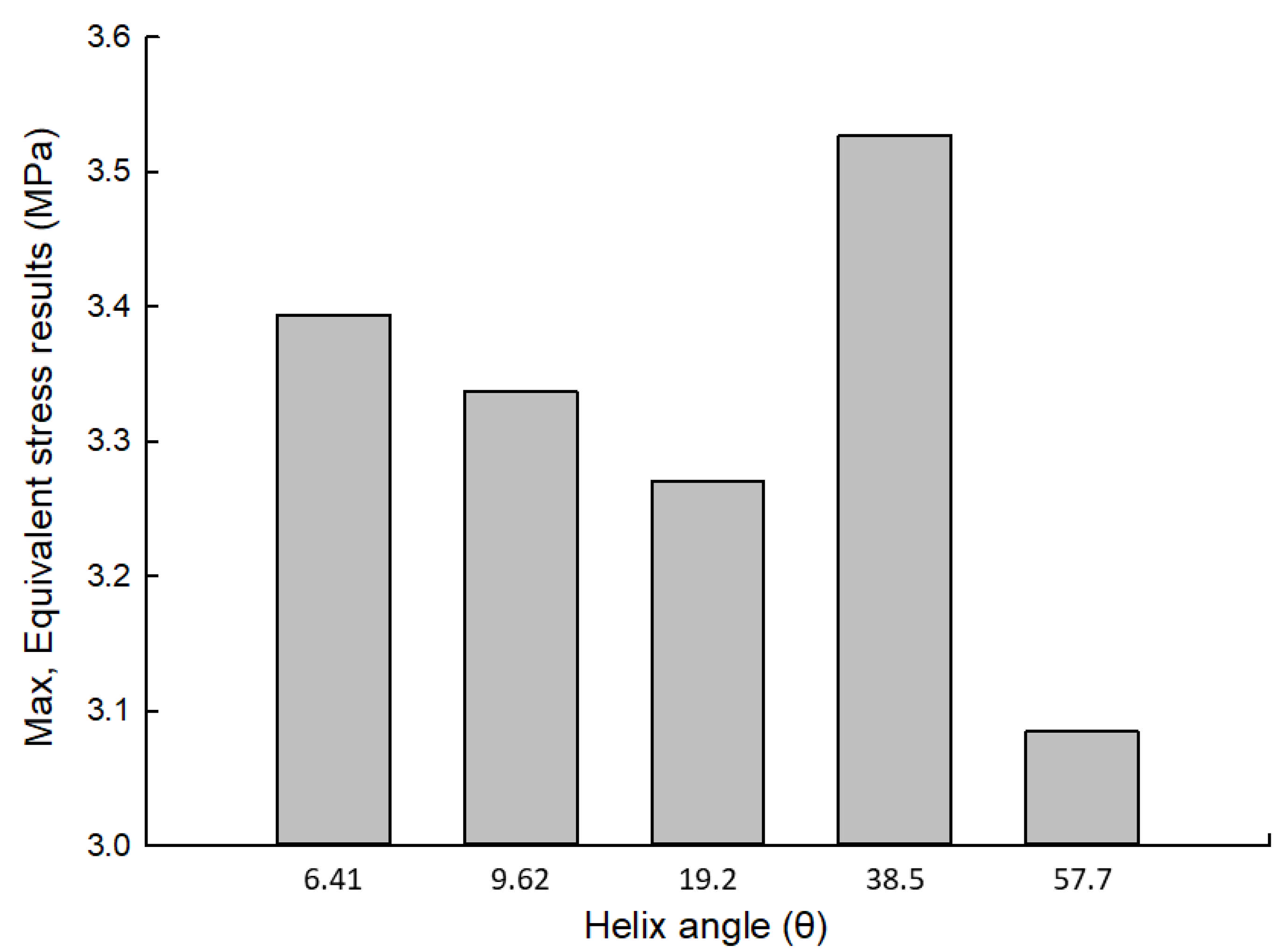
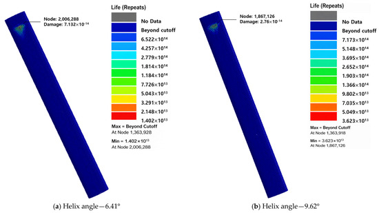
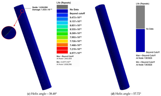
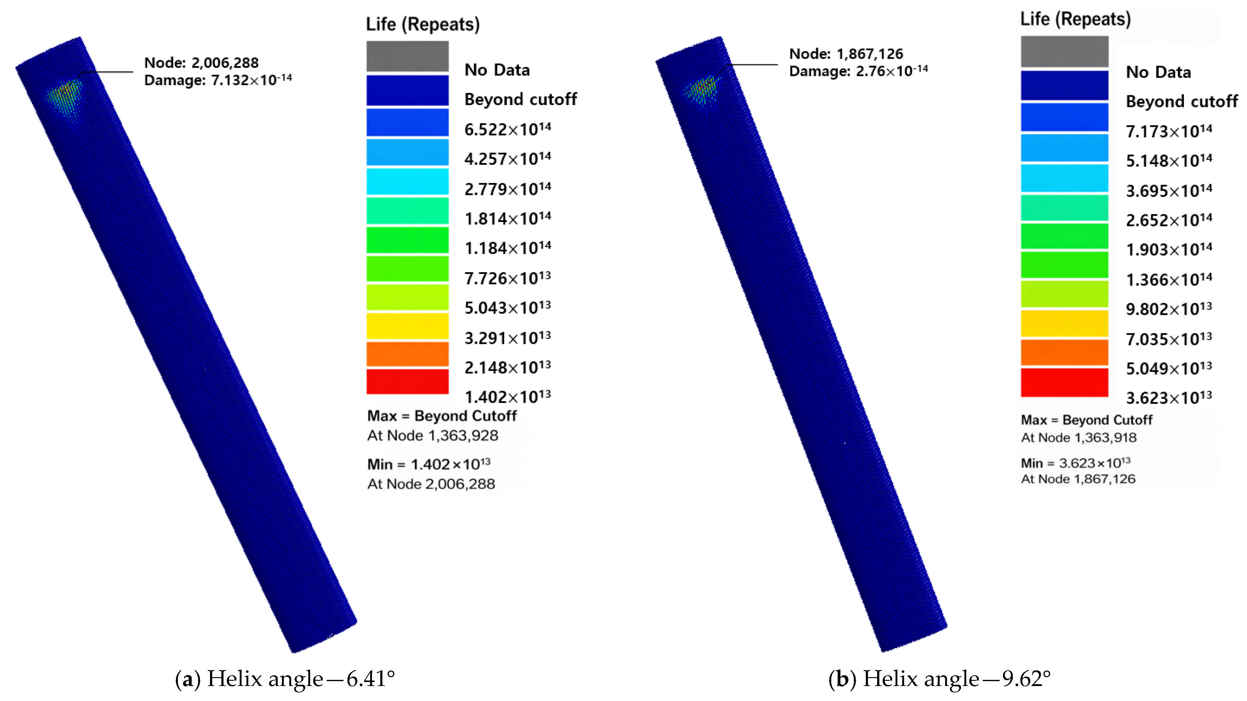
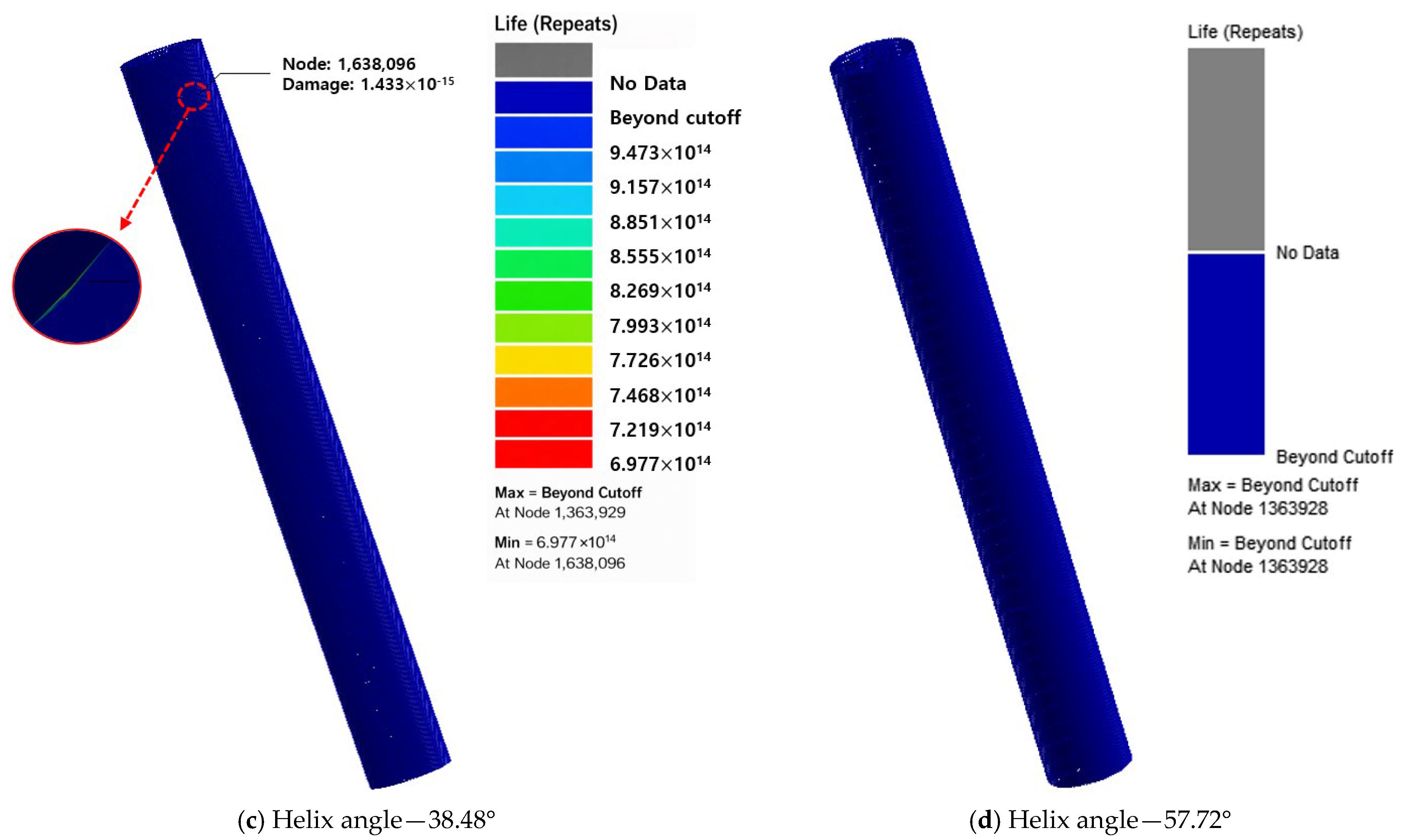
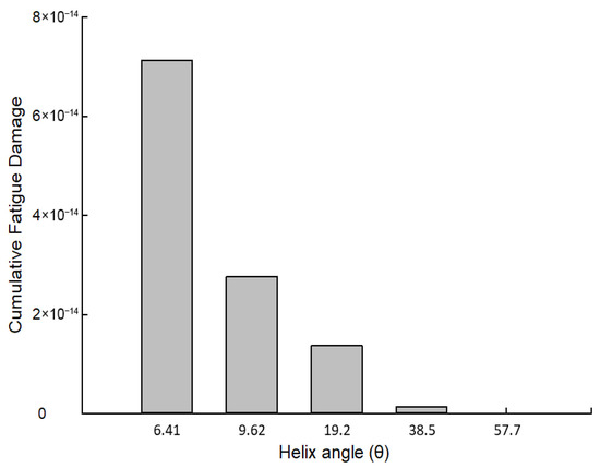
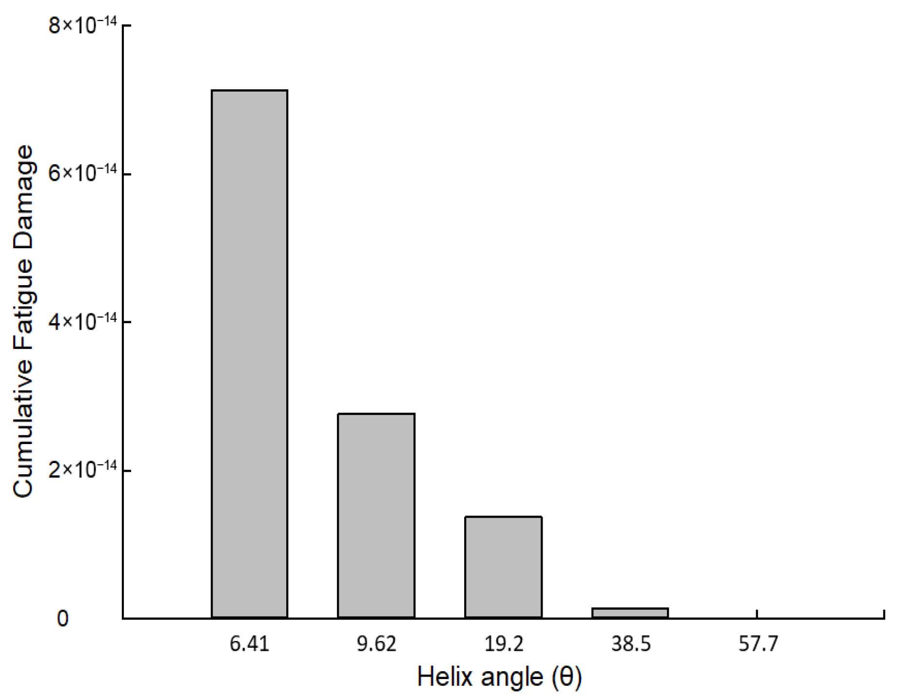
Figure 14 shows the equivalent stress distributions in the steel-wire armor of the 66 kV wet-type SPC as a function of the helix angle. For all cases considered, the maximum von Mises stress was consistently observed in the contact regions of the steel wires, where frictional interaction with adjacent layers was dominant. Among the investigated configurations, the highest stress level occurred at a helix angle of 38.48°, where the maximum von Mises stress reached approximately 3.527 MPa. This value represents an increase of approximately 7.85% compared with the reference configuration. In contrast, the lowest stress response was obtained at a helix angle of 57.72°, with a maximum von Mises stress of approximately 3.084 MPa, corresponding to a reduction of approximately 5.68% relative to the baseline case. Figure 15 shows the maximum equivalent stresses for different helix angles. As seen in the figure, the variation in the equivalent stress does not exhibit a monotonic trend with increasing helix angle. Instead, the stress response showed nonmonotonic behavior, indicating that the helix angle alone did not govern the stress distribution in a proportional manner. This nonmonotonic characteristic can be attributed to the complex coupling between bending and axial tension in the steel-wire armor, as well as changes in the interlayer contact conditions that occur with variations in the helix geometry. In particular, certain helix angle ranges promote unfavorable load-sharing and contact states, leading to localized stress amplification, while other configurations facilitate more efficient load redistribution and stress relaxation [49]. The obtained results were examined using the loading condition previously identified as fatigue-critical. Under this case, the displacement ranges were −0.4151–1.429 mm in the x-direction, −8.838–46.67 mm in the y-direction, and −0.3808–0.3399 mm in the z-direction. As shown in Figure 16, the fatigue life of the steel wire is evaluated with respect to changes in helix angle. In most cases, the minimum fatigue life was consistently observed in the upper steel wire near the fixed boundary, in agreement with previous analysis results. Among the investigated cases, the lowest fatigue life was obtained at a helix angle of 6.41°, with a predicted fatigue life of 1.402 × 10¹³ cycles. In contrast, the highest fatigue life was observed at a helix angle of 57.72°, in which the fatigue life approached infinity. These results indicate a clear trend of increasing fatigue life with increasing helix angle of the steel wire. Figure 17 illustrates the corresponding cumulative fatigue damage results, showing that the cumulative damage decreased as the helix angle increased. In particular, the cumulative fatigue damage decreased most significantly as the helix angle increased from 6.41° to 9.62°, showing a reduction of approximately 61.3%. These results indicate that, from the perspective of mechanical fatigue performance, a helix angle of around 9.62° represents a relatively favorable design range. This behavior can be attributed to the characteristics of the vertically oriented cable structure, in which transverse loading dominates the fatigue response. Under such conditions, an increase in the helix angle enhances the bending flexibility of the steel wire, thereby reducing stress concentration and resulting in lower cumulative fatigue damage.
Figure 14.
Equivalent stress distributions in the steel-wire armor of the cable as a function of the helix angle.
Figure 15.
Maximum equivalent stress for different helix angles.
Figure 16.
Variation in fatigue life with respect to the helix angle.
Figure 17.
Cumulative fatigue damage as a function of the helix angle.
5. Conclusions
A local fatigue assessment was performed using the critical loading conditions derived from the global analysis. A numerical model for the local analysis of the 66 kV wet-type SPC was developed and validated through comparisons with experimental tensile test results. Fatigue analyses were performed for 120 displacement-based time-history loading cases derived from the global dynamic response. A parametric study on the wire-armor helix angle revealed that increasing the helix angle significantly improved fatigue life by enhancing the bending flexibility and reducing the stress concentration under transverse loading. The key findings are summarized as follows:
- ▪
- Under ULS conditions, global dynamic simulation was carried out based on site-specific environmental data to obtain displacement time-series responses. The findings revealed that the response was predominantly controlled by lateral motion in the y-direction, while the vertical displacement remained relatively small owing to the vertically suspended configuration of the FPIS. The analysis confirms that wave-induced loading in the transverse direction plays a dominant role. It primarily controls both cable deformation and fatigue damage within FPIS configurations.
- ▪
- Based on the critical loading scenarios identified from the global analysis, a detailed local numerical modeling approach was developed for the 66 kV wet-type SPC. The reliability of the method was assessed through comparison with experimental tensile test outcomes. The numerical results showed good agreement with the measured data. The numerical model accurately reproduced the axial stiffness and deformation behavior of the cable, with a discrepancy of only 0.67% between the predicted and measured tensile forces at a strain level of approximately 0.293%. This close agreement confirms that the developed FE model is suitable for subsequent fatigue analysis.
- ▪
- Fatigue evaluation of 120 displacement-based load cases showed that stress concentrations were mainly confined to the metallic components, especially the steel-wire armor. The shortest fatigue life (8.71 × 10⁴ cycles) occurred near the fixed boundary. Owing to its lower fatigue resistance compared with the conductor and metallic sheath, the steel-wire armor was identified as the fatigue-critical component under FPIS operation.
- ▪
- A parametric study was conducted to quantify the influence of the wire-armor helix angle on the stress response and fatigue life. The results showed that the stress distribution and fatigue performance had a nonmonotonic dependence on the helix angle, reflecting the complex coupling between the bending, axial tension, and interlayer contact behavior. Among the investigated configurations, increasing the helix angle led to a clear improvement in fatigue life, with the highest fatigue resistance observed at a helix angle of 57.72°, where the fatigue life approached infinity. This trend was attributed to the enhanced bending flexibility of the steel wire under dominant transverse loading, which reduces the stress concentration and cumulative fatigue damage.
- ▪
- Overall, this study provides quantitative insights into the fatigue behavior of 66 kV wet-type SPCs installed using the FPIS and highlights the critical role of steel-wire armor geometry in fatigue performance. In particular, the cumulative fatigue damage decreased most significantly—by approximately 61.3%—as the helix angle increased from 6.41° to 9.62%, indicating that a helix angle of around 9.62° represents a relatively favorable design range from a mechanical fatigue perspective. These findings offer practical guidance for the design and optimization of wet-type SPCs in floating offshore wind applications, especially in terms of armor helix angle selection and identification of fatigue-critical regions
- ▪
- In this study, the validity of the numerical model in terms of mechanical response and axial stiffness was evaluated through comparison with tensile test results. However, this approach has limitations in directly capturing interlayer frictional behavior and bending responses induced by cyclic bending loads. Therefore, future work will include additional experimental and numerical validation under repeated bending conditions to further enhance the reliability of the fatigue assessment.
Author Contributions
Y.-J.K.: Conceptualization, methodology, software, validation, formal analysis, investigation, writing—original draft preparation, visualization. D.-S.H.: resources, data curation. H.-K.K.: resources, data curation. Y.-H.J.: resources, data curation. S.-W.C.: Conceptualization, methodology, software, validation, formal analysis, investigation, writing—review and editing, supervision, project administration. All authors have read and agreed to the published version of the manuscript.
Funding
This research received no external funding.
Data Availability Statement
The original contributions presented in this study are included in the article. Further inquiries can be directed to the corresponding author.
Acknowledgments
This work was supported by the Korea Institute of Energy Technology Evaluation and Planning (KETEP) grant funded by the Korea government (MOTIE) (20213000000020, Development of core equipment and evaluation technology for construction of subsea power grid for offshore wind farm).
Conflicts of Interest
Authors DongSuk Hong, HyunKyung Kim, and Yong-Hun Jung were employed by the company Taihan Cable & Solution. The remaining authors declare that the research was conducted in the absence of any commercial or financial relationships that could be construed as a potential conflict of interest.
References
- Herbert, G.M.J.; Iniyan, S.; Sreevalsan, E.; Rajapandian, S. A review of wind energy technologies. Renew. Sustain. Energy Rev. 2007, 11, 1117–1145. [Google Scholar] [CrossRef] [Scilit]
- Hannan, M.A.; Al-Shetwi, A.Q.; Mollik, M.S.; Ker, P.J.; Mannan, M.; Mansor, M.; Al-Masri, H.M.K.; Mahlia, T.M.I. Wind energy conversions, controls, and applications: A review for sustainable technologies and directions. Sustainability 2023, 15, 3986. [Google Scholar] [CrossRef] [Scilit]
- Letcher, T. (Ed.) Wind Energy Engineering: A Handbook for Onshore and Offshore Wind Turbines; Elsevier: Amsterdam, The Netherlands, 2023. [Google Scholar]
- Zhang, Z.; Liu, X.; Zhao, D.; Post, S.; Chen, J. Overview of the development and application of wind energy in New Zealand. Energy Built Environ. 2023, 4, 725–742. [Google Scholar] [CrossRef] [Scilit]
- Bilgili, M.; Alphan, H. Global growth in offshore wind turbine technology. Clean Technol. Environ. Policy 2022, 24, 2215–2227. [Google Scholar] [CrossRef] [Scilit]
- De Alegría, I.M.; Martín, J.L.; Kortabarria, I.; Andreu, J.; Ereño, P.I. Transmission alternatives for offshore electrical power. Renew. Sustain. Energy Rev. 2009, 13, 1027–1038. [Google Scholar] [CrossRef] [Scilit]
- Tom, F. Study of Dynamic Cables Layout of Floating Wind Turbines to Optimize Installation and Cost. Master’s Thesis, Université de Liège, Liège, Belgique, 2024. [Google Scholar]
- Georgallis, G. Submarine cables. In The Global Cable Industry: Materials, Markets, Products; Wiley-VCH: Weinheim, Germany, 2021; pp. 291–310. [Google Scholar]
- Resner, L.; Paszkiewicz, S. Radial water barrier in submarine cables, current solutions and innovative development directions. Energies 2021, 14, 2761. [Google Scholar] [CrossRef] [Scilit]
- Cerik, B.C.; Huang, L. Recent advances in mechanical analysis and design of dynamic power cables for floating offshore wind turbines. Ocean Eng. 2024, 311, 118810. [Google Scholar] [CrossRef] [Scilit]
- Thies, P.R.; Harrold, M.; Johanning, L.; Grivas, K.; Georgallis, G. Load and Fatigue Evaluation for 66 KV Floating Offshore Wind Submarine Dynamic Power Cable. Jicable 2019. Available online: https://ore.exeter.ac.uk/articles/conference_contribution/Load_and_fatigue_evaluation_for_66kV_floating_offshore_wind_submarine_dynamic_power_cable/29766203 (accessed on 6 June 2023).
- Bakken, K. Fatigue of Dynamic Power Cables Applied in Offshore Wind Farms. Master’s Thesis, Norwegian University of Science and Technology, Trondheim, Norway, 2019. [Google Scholar]
- Zhao, S.; Cheng, Y.; Chen, P.; Nie, Y.; Fan, K. A comparison of two dynamic power cable configurations for a floating offshore wind turbine in shallow water. AIP Adv. 2021, 11, 039221. [Google Scholar] [CrossRef] [Scilit]
- Shim, D.; Kim, M.S.; Kim, C.; Rho, Y.; Lee, J.; Chea, K.; Kim, K.; Jeong, D. A fundamental study of VIV fatigue analysis procedure for dynamic power cables subjected to severely sheared currents. J. Soc. Nav. Arch. Korea 2023, 60, 375–387. [Google Scholar] [CrossRef] [Scilit]
- Rentschler, M.U.T.; Adam, F.; Chainho, P. Design optimization of dynamic inter-array cable systems for floating offshore wind turbines. Renew. Sustain. Energy Rev. 2019, 111, 622–635. [Google Scholar] [CrossRef] [Scilit]
- Ballard, B.; Yu, Y.-H.; Rij, J.V.; Driscoll, F. Umbilical fatigue analysis for a wave energy converter. In Proceedings of the ASME 39th International Conference on Ocean, Offshore and Arctic Engineering, Virtual, 3–7 August 2020. [Google Scholar]
- Hu, H.; Yan, J.; Sævik, S.; Ye, N.; Lu, Q.; Bu, Y. Nonlinear bending behavior of a multilayer copper conductor in a dynamic power cable. Ocean Eng. 2022, 250, 110831. [Google Scholar] [CrossRef] [Scilit]
- Nasution, F.P.; Sævik, S.; Gjøsteen, J.K.Ø. Fatigue analysis of copper conductor for offshore wind turbines by experimental and FE method. Energy Procedia 2012, 24, 271–280. [Google Scholar] [CrossRef] [Scilit]
- Nasution, F.P.; Sævik, S.; Gjøsteen, J.K.Ø. Finite element analysis of the fatigue strength of copper power conductors exposed to tension and bending loads. Int. J. Fatigue 2014, 59, 114–128. [Google Scholar] [CrossRef] [Scilit]
- Karlsen, S.; Slora, R.; Heide, K.; Lund, S.; Eggertsen, F.; Osborg, P.A. Dynamic Deep-Water Power Cables. RAO/CIS Offshore, 2009. Available online: https://books-fmf.clan.su/_ld/1/101_DYNAMICDEEPWATE.pdf (accessed on 6 June 2023).
- Knych, T.; Smyrak, B.; Jurkiewicz, B. A Comparative Analysis of the Fatigue Strength of Aluminium and Copper Wires Used for Power Cables. Materials 2025, 18, 4426. [Google Scholar] [CrossRef] [Scilit]
- Svensson, G. Fatigue Prediction Models of Dynamic Power Cables by Laboratory Testing and FE Analysis. Master’s Thesis, Norwegian University of Science and Technology, Trondheim, Norway, 2020. [Google Scholar]
- Marta, M.; Mueller-Schuetze, S.; Ottersberg, H. Development of Dynamic Submarine MV Power Cable Design Solutions for Floating Offshore Renewable Energy Applications. Jicable 2015. Available online: https://ore.exeter.ac.uk/articles/conference_contribution/Development_of_dynamic_submarine_MV_power_cable_design_solutions_for_floating_offshore_renewable_energy_applications/29709344 (accessed on 6 June 2023).
- Thies, P.R.; Johanning, L.; Smith, G.H. Assessing mechanical loading regimes and fatigue life of marine power cables in marine energy applications. Proc. Inst. Mech. Eng. Part O J. Risk Reliab. 2012, 226, 18–32. [Google Scholar] [CrossRef] [Scilit]
- Said, J.; Garcin, S.; Fouvry, S.; Cailletaud, G.; Yang, C.; Hafid, F. A multi-scale strategy to predict fretting-fatigue endurance of overhead conductors. Tribol. Int. 2020, 143, 106053. [Google Scholar] [CrossRef] [Scilit]
- Said, J.; Fouvry, S.; Cailletaud, G.; Yang, C.; Hafid, F. Shear driven crack arrest investigation under compressive state: Prediction of fretting fatigue failure of aluminium strands. Int. J. Fatigue 2020, 136, 105589. [Google Scholar] [CrossRef] [Scilit]
- Zhou, P.; Gao, Y.; Wang, L.; Li, L. Investigation on dynamic response of J-tube submarine cable around monopile foundation. Appl. Ocean Res. 2025, 154, 104319. [Google Scholar] [CrossRef] [Scilit]
- Hamdan, M.A.; Pilgrim, J.A.; Lewin, P.L. Analysis of thermo-mechanical stress in three core submarine power cables. IEEE Trans. Dielectr. Electr. Insul. 2020, 27, 1288–1296. [Google Scholar] [CrossRef] [Scilit]
- Panza, L. Mechanical Performance Study of Submarine Power Cables. Ph.D. Thesis, Politecnico di Torino, Torino, Italy, 2020. [Google Scholar]
- DNV Technology Centre. Free Spanning Pipelines: Recommended Practice DNV-RP-F105; Det Norske Veritas: Singapore, 2002. [Google Scholar]
- Johannesson, P.; Lang, X.; Johnson, E.; Ringsberg, J.W. Mechanical reliability analysis of flexible power cables for marine energy. J. Mar. Sci. Eng. 2022, 10, 716. [Google Scholar] [CrossRef] [Scilit]
- Gorash, Y.; Comlekci, T.; MacKenzie, D. Comparative study of FE-models and material data for fatigue life assessments of welded thin-walled cross-beam connections. Procedia Eng. 2015, 133, 420–432. [Google Scholar] [CrossRef] [Scilit]
- Silva, J.A.; Caetano, D.A.; Filho, S.L.M.R.; Teixeira, F.N.; Guimarães, L.G.M. Calculation and enhancement of fatigue life by ε-N approach and corrosion fatigue in steam turbine rotor. Int. J. Damage Mech. 2022, 31, 845–863. [Google Scholar] [CrossRef] [Scilit]
- Chen, S.; Yang, Y.; Wang, T.; Zhang, J. Analysis of fatigue characteristics of gears based on NCode DesignLife. IOP Conf. Ser. Mater. Sci. Eng. 2019, 542, 012076. [Google Scholar]
- Lee, H.H. Finite Element Simulations with ANSYS Workbench 2020; SDC Publications: Mission, KS, USA, 2020. [Google Scholar]
- Nexans Norway AS. Subsea Composite Cable OM1052; Nexans Norway AS: Oslo, Norway, 2022. [Google Scholar]
- Beier, D.; Schnepf, A.; Van Steel, S.; Ye, N.; Ong, M.C. Fatigue analysis of inter-array power cables between two floating offshore wind turbines including a simplified method to estimate stress factors. J. Mar. Sci. Eng. 2023, 11, 1254. [Google Scholar] [CrossRef] [Scilit]
- DNV. GL AS DNVGL-RP-0005 RP-C203: Fatigue Design of Offshore Steel Structures; DNV: Høvik, Norway, 2014. [Google Scholar]
- Fang, P.; Li, X.; Jiang, X.; Hopman, H.; Bai, Y. Development of an effective modelling method for the mechanical analysis of submarine power cables under bending. Compos. Struct. 2025, 366, 119198. [Google Scholar] [CrossRef] [Scilit]
- Moreno, E. Geometrical Irregularities Effect on Lead Sheathing for Submarine Power Cable Applications. Ph.D. Thesis, Politecnico di Torino, Torino, Italy, 2020. [Google Scholar]
- Tuckart, W.; Molinari, E.; Rossit, D.; Failla, M. Friction and wear behavior of irradiated polyethylene sliding against a rough steel surface. Tribol. Lett. 2014, 55, 165–176. [Google Scholar] [CrossRef] [Scilit]
- Bouaziz, O.; Masse, J.P.; Allain, S.; Orgéas, L.; Latil, P. Compression of crumpled aluminum thin foils and comparison with other cellular materials. Mater. Sci. Eng. A 2013, 570, 1–7. [Google Scholar] [CrossRef] [Scilit]
- Conseil International des Grands Réseaux Électriques (CIGRÉ). Recommendations for Mechanical Testing of Submarine Cables; CIGRÉ Study Committee B1: Paris, France, 2015. [Google Scholar]
- Fang, P. Development of an Effective Modelling Method for the Local Mechanical Analysis of Submarine Power Cables. Ph.D. Thesis, Delft University of Technology, Delft, The Netherlands, 2024. [Google Scholar]
- Benato, R.; Sessa, S.D.; Forzan, M.; Marelli, M.; Pietribiasi, D. Core laying pitch-long 3D finite element model of an AC three-core armoured submarine cable with a length of 3 metres. Electr. Power Syst. Res. 2017, 150, 137–143. [Google Scholar] [CrossRef] [Scilit]
- Giussani, L.; Di Rienzo, L.; Bechis, M.; De Falco, C. Fully coupled computation of losses in metallic sheaths and armor of AC submarine cables. IEEE Trans. Power Deliv. 2021, 37, 3803–3812. [Google Scholar] [CrossRef] [Scilit]
- IEC Standard 60287; Electric Cables—Calculation of the Current Rating. IEC: Singapore, 2006.
- Giussani, L.; Di Rienzo, L.; Bechis, M.; De Falco, C. Computation of armor losses in AC submarine cables. IEEE Trans. Power Deliv. 2020, 36, 3014–3021. [Google Scholar] [CrossRef] [Scilit]
- Wang, H.; Yang, Z.; Yan, J.; Wang, G.; Shi, D.; Zhou, B.; Li, Y. Prediction method and validation study of tensile performance of reinforced armor layer in marine flexible pipe/cables. J. Mar. Sci. Eng. 2022, 10, 642. [Google Scholar] [CrossRef] [Scilit]

Disclaimer/Publisher’s Note: The statements, opinions and data contained in all publications are solely those of the individual author(s) and contributor(s) and not of MDPI and/or the editor(s). MDPI and/or the editor(s) disclaim responsibility for any injury to people or property resulting from any ideas, methods, instructions or products referred to in the content. |
© 2026 by the authors. Licensee MDPI, Basel, Switzerland. This article is an open access article distributed under the terms and conditions of the Creative Commons Attribution (CC BY) license.