


Abstract
To find out the combined effect of seismic action, seepage, and sandy and argillaceous interlayers on the seabed slope stability, the safety factors of seabed slopes, which include sandy and argillaceous interlayers, under different hydraulic gradients and seismic loads, were calculated using the geotechnical simulation software Geo-Studio 2012. Results demonstrate that both seismic action and seepage exert significant impacts on seabed slope stability: seismic loads play a dominant role in governing slope stability, while seepage acts as a key triggering factor for slope failure. With the gradual increase in seismic load magnitude, the influence of seepage hydraulic gradient on slope safety factor decreases progressively. For homogeneous segregated slopes, which consist of silty clay, a higher seepage hydraulic gradient reduces the magnitude of critical seismic load that induces slope instability. Under identical seismic load and hydraulic gradient conditions, seabed slopes with sandy interlayers exhibit higher stability compared to homogeneous soil slopes, whereas slopes with argillaceous interlayers show reduced stability.
1. Introduction
With the advancement of China’s maritime power strategy, the exploitation of marine resources and the construction of marine engineering projects are rapidly expanding from nearshore shallow waters to deep and distant seas. The scale and density of projects such as submarine pipeline laying, offshore wind power foundation construction, and deep-sea oil and gas platform erection are constantly increasing. As the bearing substrate of marine engineering facilities, the stability of seabed slopes is directly related to the operational safety of engineering projects and the balance of marine ecosystems, thus emerging as a core research topic in the field of marine geological engineering [1,2].
The marine environment where seabed slopes are located is characterized by both complexity and particularity, and the stability of seabed slopes is governed by the coupling effects of multiple factors. From a geological perspective, sediment types, physical and mechanical parameters of soil mass, stratum structure, and the occurrence state of natural gas hydrates all exert significant impacts on the stability of seabed slopes [3,4,5]. From the perspective of the marine dynamic environment, the cyclic loads induced by waves, tides, and ocean currents can lead to the accumulation of pore water pressure in soil mass, thereby reducing its effective stress and shear strength [6,7]. Meanwhile, abrupt disturbances such as extreme storm surges and earthquakes are more prone to triggering large-scale submarine landslides [8]. Existing studies have demonstrated that the seepage of submarine groundwater can affect the stability of seabed slopes [9,10,11]. Based on the research of Ocean Drilling Program (ODP) Hole 1073, Dugan et al. [9] pointed out that the under-compaction of Miocene to Pleistocene sediments on the New Jersey continental slope was caused by high fluid pressure derived from seepage through permeable formations and pressure equilibrium, and such pressure may induce slope instability in passive continental margins worldwide. Through investigations of the Nice and the French Riviera region, Witt et al. [12] indicated that overpressure in sedimentary layers induced by submarine groundwater seepage is one of the triggering factors for submarine slope instability in this area. Furthermore, they confirmed the existence of submarine groundwater seepage by measuring groundwater tracer elements, though this seepage did not result in a significant increase in pore water pressure. These findings will contribute to the further assessment of submarine landslide disaster risks in the region. Paull et al. [13] conducted surveys at five stations on the continental slope of the Beaufort Sea, Canada, using autonomous underwater vehicles (AUVs) and remotely operated vehicles (ROVs). The results showed that the formation of large-scale submarine landslide traces in this area may be associated with the seepage of subsurface fluids and the action of overpressure. However, the impact of pore water salinity changes caused by groundwater seepage at the slip surface on seabed slope stability had not previously attracted attention in the field of marine geology. Currently, research on seabed slope stability has evolved from traditional limit equilibrium methods toward multi-field coupling numerical simulation and probabilistic risk assessment. The application of software such as Geo-Slope and FLAC3D has also improved the analysis accuracy. However, constrained by difficulties in marine in situ monitoring, the complexity of soil dynamic constitutive relations, and unclear multi-factor coupling mechanisms, key issues remain unresolved, including slope stress response under complex marine dynamics, excess pore water pressure evolution induced by hydrate dissociation, and instability critical thresholds under extreme working conditions. Therefore, systematically conducting research on seabed slope stability, revealing the multi-factor coupling instability mechanism, and establishing an accurate assessment system and prevention and control technologies are of great theoretical value and practical significance for ensuring the safety of marine engineering, reducing geological disaster risks, and promoting the sustainable development of marine resources.
In this study, the geotechnical calculation software Geo-Studio 2012 was employed to investigate and analyze the influence of seepage on seabed slope stability under seismic loads. The safety factors of seabed slopes under different hydraulic gradients and different seismic loads were obtained through calculations. Additionally, the effects of sandy interlayers and argillaceous interlayers on slope stability were analyzed and calculated.
2. Methods
2.1. Model Geometric Dimensions
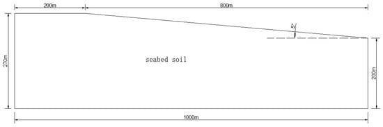
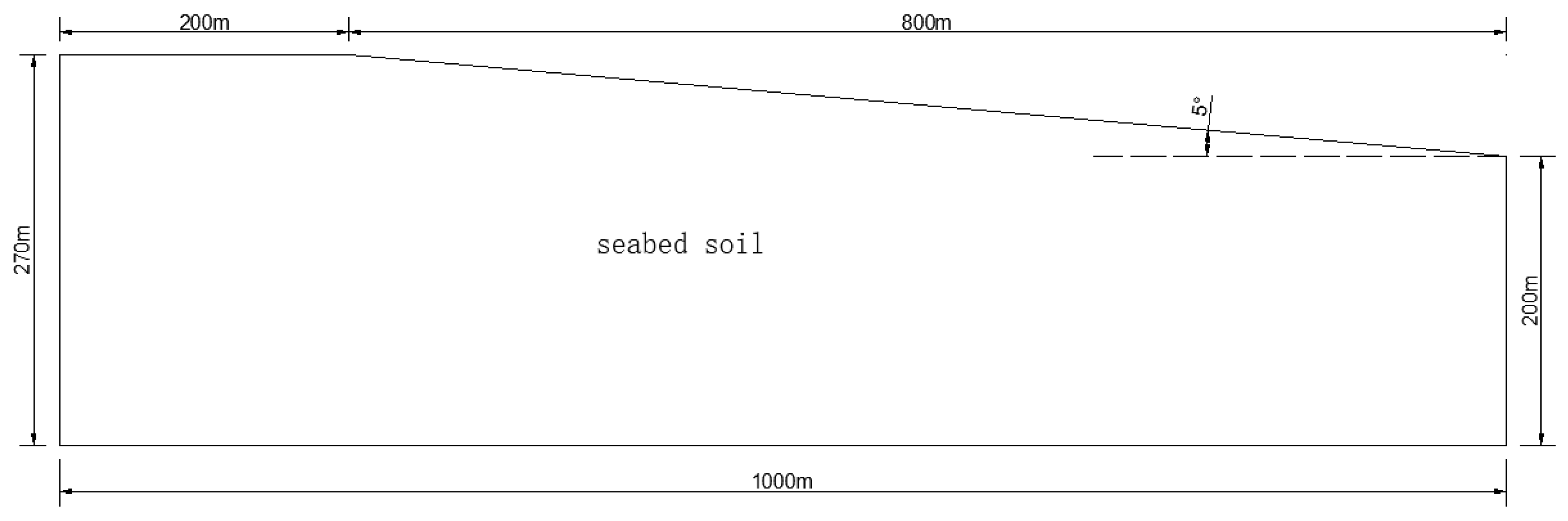
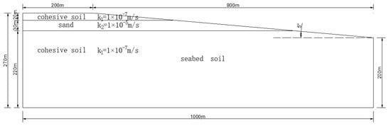
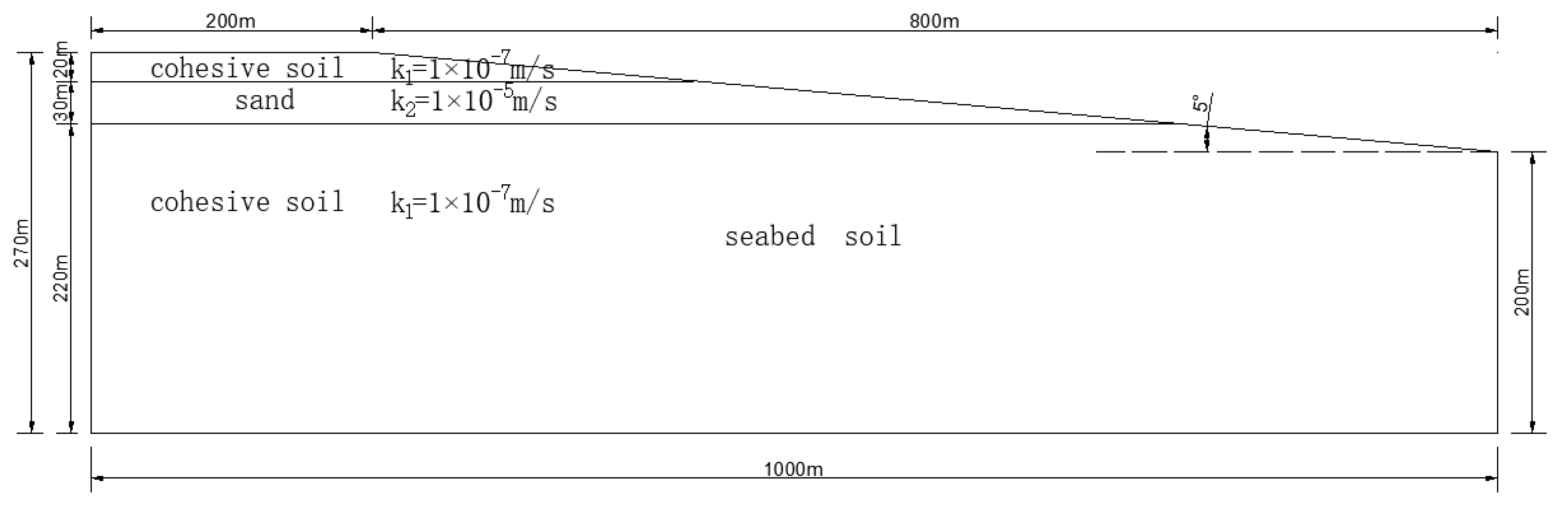
A seabed slope model was established in Geo-Studio 2012 software, with a total length of 1000 m, a soil thickness of 270 m at the left boundary, 200 m at the right boundary, a slope segment length of 800 m, a height difference of 70 m, and a slope angle of 5°, as shown in Figure 1.
Figure 1.
Schematic of the seabed slope model.
2.2. Soil Parameters
The soil parameters of the model adopt various indicators of common continental shelf silty clay [14]. The saturated unit weight γsat of the soil is 16.4 kN/m3, cohesion c is 10.2 kPa, internal friction angle Φ is 32.5°, and hydraulic conductivity k is 1 × 10⁻⁷ m/s. In the stability calculation, the Mohr–Coulomb model is adopted as the soil constitutive model.
2.3. Seepage Analysis
Total water heads with specific values, denoted as Hleft and Hright, are applied to the left and right boundaries of the model, respectively. If Hleft > Hright, seepage from left to right will occur in the model soil, and the hydraulic gradient i is calculated as i = (Hleft − Hright)/L (where L is the total length of the model). If Hleft = Hright, no seepage will occur in the model soil.
The horizontal left-to-right seepage setup is consistent with the natural geological and hydrological characteristics of continental shelf seabed slopes, which are inherently elevated on the nearshore side (left) and lower on the offshore side (right). This topographic feature forms a hydraulic head difference between nearshore and offshore areas, with higher groundwater levels in nearshore zones driving the primary horizontal seepage seaward—this is the core geological factor for the hydraulic gradient in the model. In addition, heterogeneous stratification and deep sediment compaction-induced overpressure further contribute to seepage in actual seabed slopes, while marine dynamic processes (wave/tide fluctuations, seismic disturbances) can temporarily alter pore water pressure and exacerbate seepage, all of which align with the seepage mechanism of the modeled slope.
Left-to-right seepage generates a seepage force acting on the soil mass toward the right, which is detrimental to slope stability, whereas a reverse right-to-left seepage would produce a stabilizing force opposing potential slope sliding. Since the research focus is on the adverse effects of seepage coupled with seismic loads on seabed slope stability, the stabilizing reverse seepage scenario is not considered in the present analysis. The model adopts an impermeable bottom boundary, and though such boundary settings have certain limitations, all model boundaries are set at a certain distance from the slope shoulder. Given that this study focuses on seepage effects on slope stability, particularly the slope shoulder, the influence of boundary conditions is not a dominant factor in the analysis.
2.4. Slope Stability Calculation Under Seismic Loads
The seismic load is applied to the model soil using the pseudo-static method, and the load levels are shown in Table 1. The pseudo-static method is a widely used simplified approach for seismic slope stability analysis in geotechnical engineering. It treats seismic load as an equivalent static inertial force via horizontal and vertical seismic coefficients kh and kv, which are combined with static loads within a limit equilibrium framework. By incorporating these inertial forces into traditional methods such as Bishop’s, Janbu’s, or Spencer’s, the factor of safety can be efficiently calculated. This method is simple, computationally efficient, and compatible with standard design procedures [15].
Table 1.
Seismic loads for different seismic intensities (pseudo-static method).
After the application of horizontal seismic loads, the safety factor Ks of the seabed slope under the coupled action of soil self-weight, seepage, and seismic loads can be calculated using the built-in Ordinary method (i.e., the classic slice method, which does not consider the inter-slice forces) in the software. In the Ordinary method (also named the Swedish Method of Slices), the safety factor Ks can be calculated by the equation below:
in which Fs denotes the safety factor of slope, Wi denotes weight of the i-th soil slice, αi denotes inclination angle of the slip surface at the base of the i-th slice with respect to the horizontal direction, ui represents the pore water pressure at the base of the i-th slice, bi is width of the i-th soil slice, ci is cohesion of the soil at the base of the i-th slice, and Φi is internal friction angle of the soil at the base of the i-th slice.
3. Results and Discussion
3.1. Influence of Hydraulic Gradient on Seabed Slope Stability Under Different Seismic Loads
The slope soil is subjected to the coupled action of self-weight, seepage force, and horizontal seismic force. To investigate the influence of hydraulic gradient on seabed slope stability under different seismic loads, targeted calculations were conducted. The specific working conditions and results are shown in Table 2.
Table 2.
Calculation conditions and results under different seismic loads.
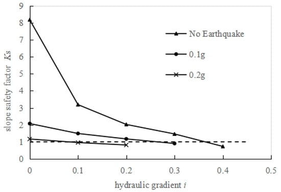
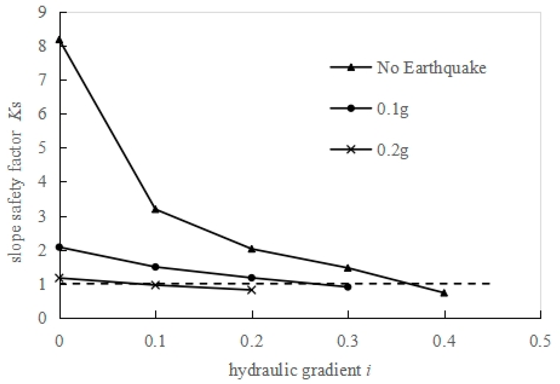
It is evident that in the absence of seismic load, when the hydraulic gradient is 0 (no seepage, Working Condition # 000), the overall stability of the seabed slope is excellent, with a safety factor of 8.173. As the hydraulic gradient increases continuously, the seepage velocity also increases, and the slope safety factor decreases gradually. When the hydraulic gradient is 0.4 (Working Condition # 400), the average seepage velocity reaches 3.87 × 10⁻⁸ m/s, and the safety factor at this time is 0.731 < 1.0, indicating that the slope loses stability. When the seismic load is 0.1 g, with the increase in hydraulic gradient, the slope safety factor decreases gradually. When the hydraulic gradient is 0.3, the average seepage velocity is 2.86 × 10⁻⁸ m/s, and the safety factor is 0.903 < 1.0, leading to slope instability. The same trend is observed when the seismic load is 0.2 g; however, the slope loses stability when the hydraulic gradient is 0.1, with a safety factor of 0.958. The relationship curves between hydraulic gradient and safety factor under different seismic loads are shown in the following Figure 2. The equation of the horizontal dotted line in Figure 2 is K = 1.0; once a spot is below the dotted line, that means the slope under a certain working condition is a failure.
Figure 2.
Relationship curve between seepage hydraulic gradient i and seabed slope safety factor Ks under different seismic loads.
As illustrated in Figure 2, with the gradual increase in seismic load, the influence of seepage hydraulic gradient on the slope safety factor diminishes progressively. When the seismic load is 0 (i.e., in the absence of seismic action), the safety factor decreases remarkably with variations in hydraulic gradient; in contrast, when the seismic load reaches 0.2 g, the slope of the curve becomes extremely small. It can therefore be concluded that seismic load is the most critical factor governing seabed slope stability, whereas seepage only plays a secondary and relatively minor role. Although seepage does affect slope stability, its influence is considerably weaker than that of seismic loading.
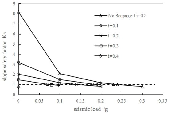
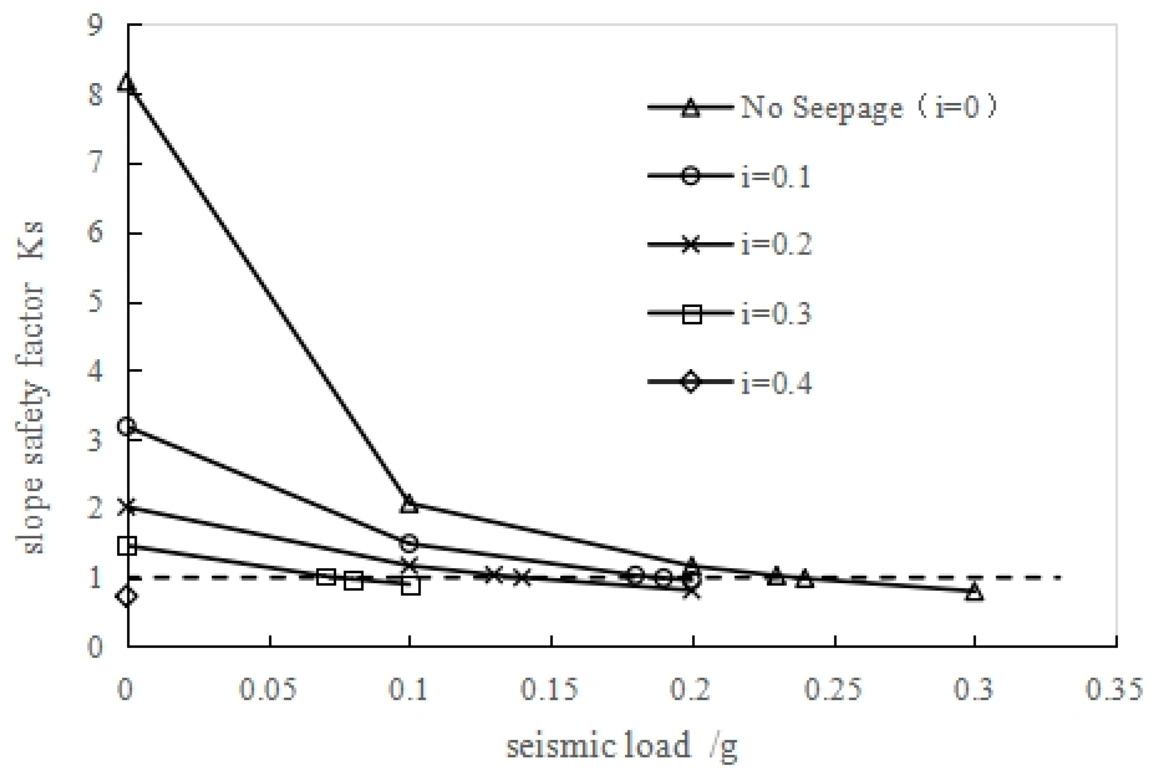
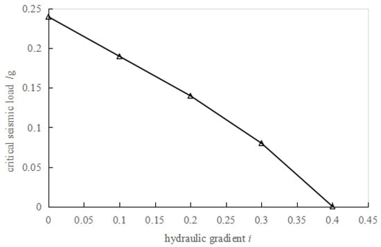
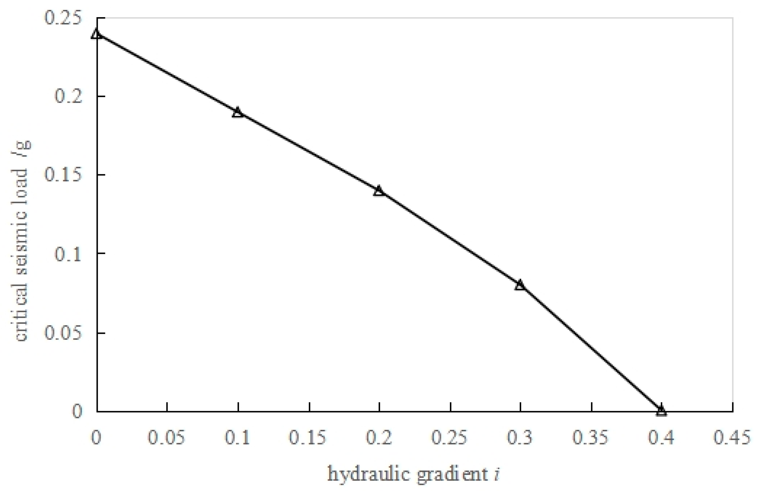
Based on the data in Table 2, the relationship curves between seismic load and seabed slope safety factor Ks under different hydraulic gradients are illustrated in Figure 3. As can be seen from the Figure, in the absence of seepage (i = 0), the slope safety factor decreases gradually with the increase in seismic load. When the seismic load is 0.24 g, the safety factor is 0.988 < 1.0, indicating that the slope loses stability. When the hydraulic gradient i = 0.1, the slope loses stability when the seismic load reaches 0.19 g. With the continuous increase in hydraulic gradient, the seismic load corresponding to slope instability decreases progressively. When the hydraulic gradients are 0.2, 0.3, and 0.4 respectively, the seismic loads corresponding to slope instability are 0.14 g, 0.08 g, and 0 g. If the seismic load at which instability occurs is referred to as the “critical seismic load”, the critical seismic loads corresponding to different hydraulic gradients are shown in Figure 4. It can be observed that the larger the hydraulic gradient, the smaller the critical seismic load corresponding to slope instability.
Figure 3.
Relationship curve between seismic load and seabed slope safety factor Ks under different hydraulic gradients.
Figure 4.
Critical seismic loads corresponding to different hydraulic gradients.
3.2. Influence of Sandy Interlayer on Seabed Slope Stability
To investigate the influence of the sandy interlayer in seabed soil on seabed slope stability, based on the slope model illustrated in Figure 1, the soil within the range of 20 m to 50 m below the slope crest was replaced with sand, as shown in Figure 5, and stability analysis was performed on it. The permeability coefficient of cohesive soil (k1) remains 1 × 10⁻⁷ m/s (consistent with the previous section), and the permeability coefficient of sand (k2) is set to 1 × 10⁻⁵ m/s. The strength parameters are the same as those of cohesive soil, namely, the saturated unit weight (γ) is 16.4 kN/m3, the cohesion (c) is 10.2 kPa, and the internal friction angle (Φ) is 32.5°. The specific calculation working conditions and results are presented in Table 3.
Figure 5.
Schematic diagram of seabed slope with sandy interlayers.
Table 3.
Calculation conditions and results for stability analysis of seabed slopes with sandy interlayers.
As indicated by the results, when seismic loads are not applied and the hydraulic gradient is zero (corresponding to the no-seepage scenario; Working Condition # 000 *), the entire seabed slope exhibits superior overall stability, with a calculated safety factor of 8.173. This finding aligns with the stability performance of the seabed slope lacking a sandy interlayer; the reason lies in the fact that the high permeability of the sand layer does not impact slope stability in the absence of seepage flow.
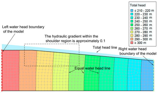
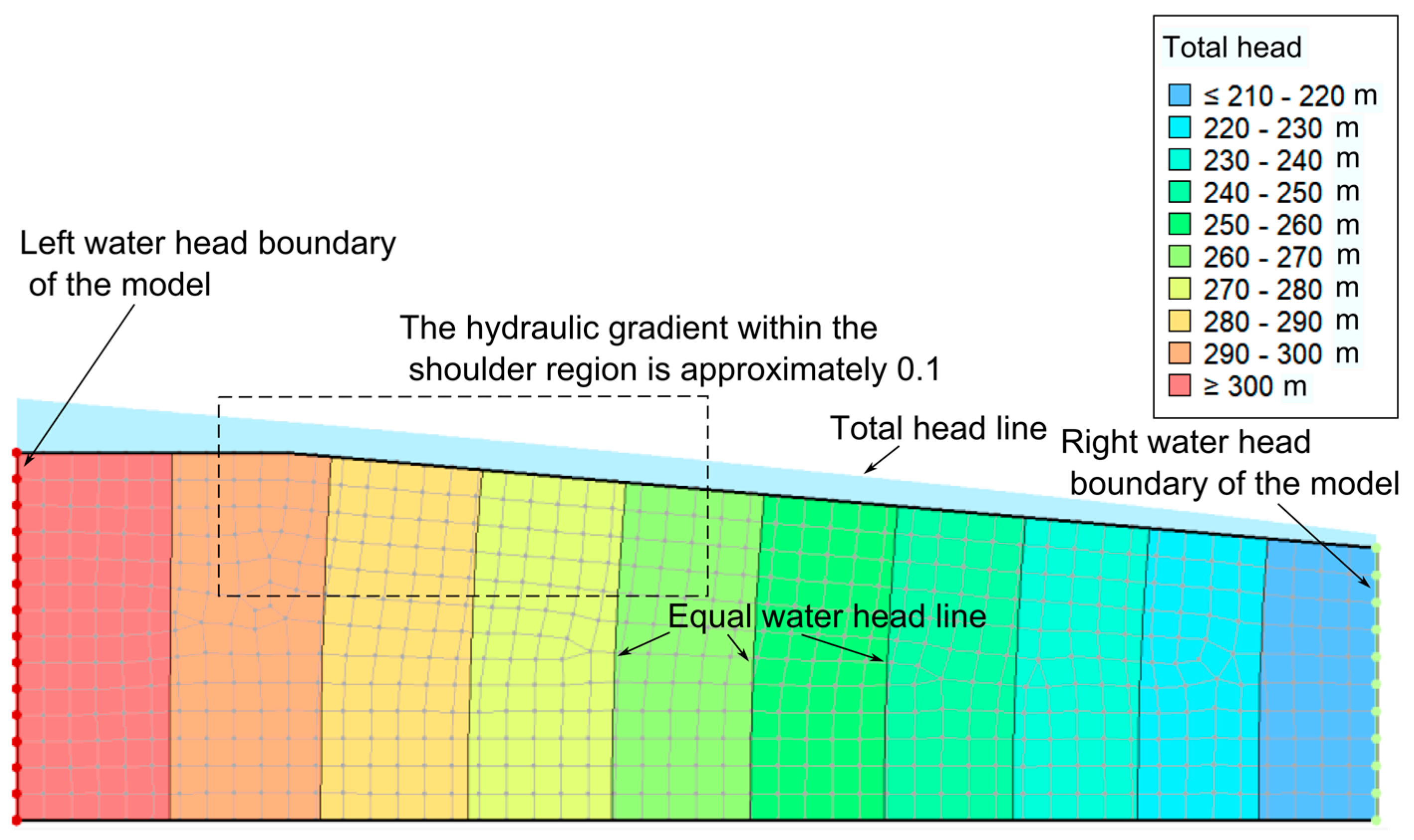
When the hydraulic gradient is 0.1 (Working Condition # 100 *), seepage occurs in the seabed slope. The seepage velocity of water flow in the sandy interlayer is 1.69 × 10⁻⁷ m/s, and that in the cohesive soil layer is 2.84 × 10⁻⁸ m/s. At this time, the safety factor is 6.369, which is higher than 3.186, which is the safety factor of the homogeneous soil slope under Working Condition # 100 (Table 2). The existence of the sandy interlayer improves the stability of the seabed slope. The total head distribution diagrams under the above two working conditions are shown in Figure 6.
Figure 6.
Total head distribution of seabed slope (Working Condition #100, homogeneous soil slope).
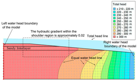
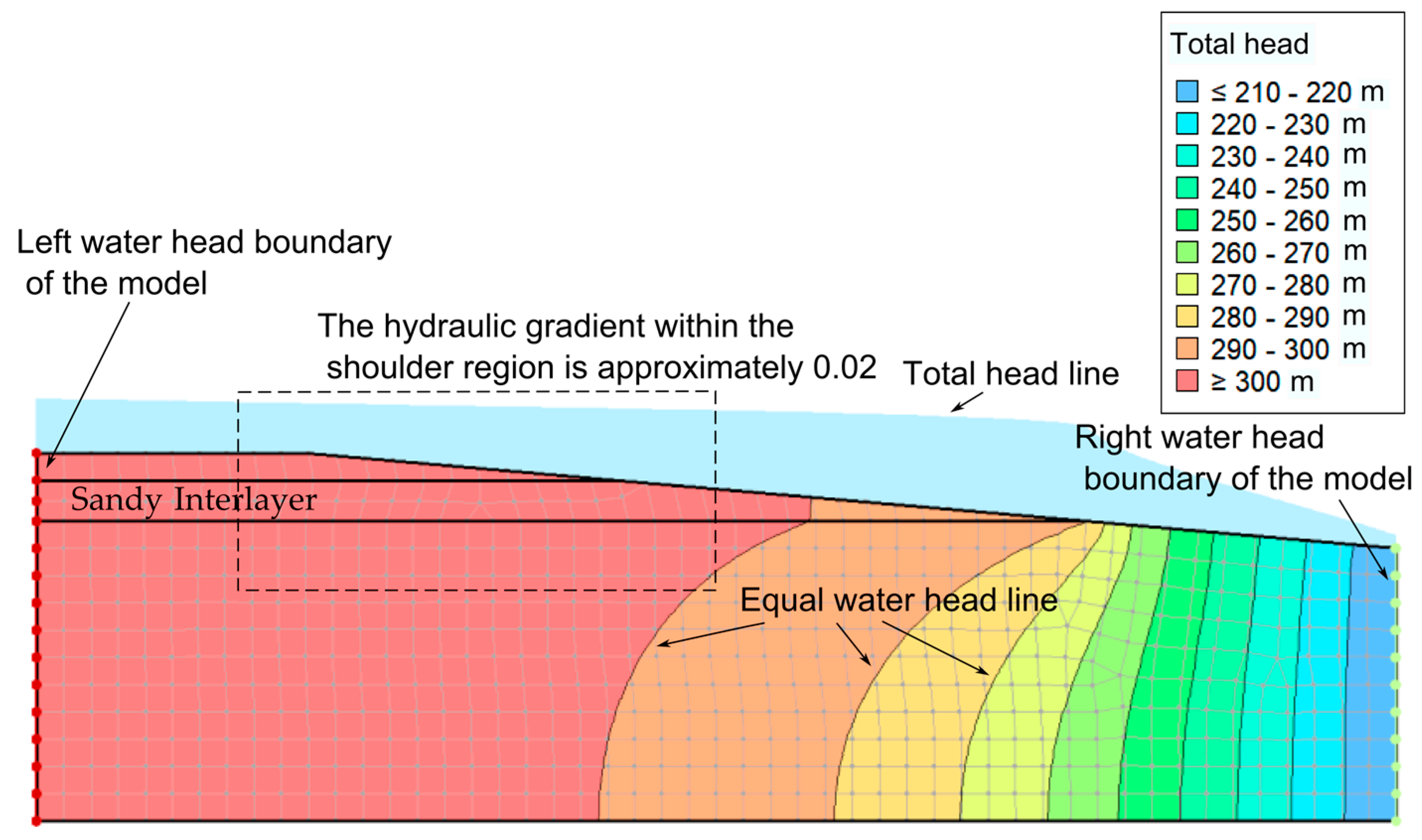
As depicted in Figure 6, for a seabed slope composed of homogeneous cohesive soil, the total hydraulic head decreases uniformly across the entire slope during seepage, with the hydraulic gradient at the slope shoulder reaching approximately 0.1. By contrast, when the slope contains a sandy interlayer (e.g., Working Condition # 100 * in Figure 7), the high permeability and low flow resistance of the sand layer result in only a marginal reduction in total hydraulic head within the interlayer’s distribution range. Correspondingly, the hydraulic gradient at the slope shoulder diminishes to around 0.02, a value substantially lower than that observed in the homogeneous cohesive soil slope. According to the seepage force formula j = i × γw (where j denotes seepage force, i represents hydraulic gradient, and γw is the unit weight of water), this reduction in hydraulic gradient translates to a smaller seepage force at the slope shoulder under Working Condition # 100 * compared with Working Condition # 100, thereby enhancing the slope stability safety factor.
Figure 7.
Total head distribution of seabed slope (Working Condition # 100 *, sandy interlayer).
Notably, a significant hydraulic gradient emerges in the region extending from the pinch-out edge on the right side of the sandy interlayer to the right boundary of the numerical model. This phenomenon stems from two key modeling constraints: first, the total hydraulic head at the right model boundary was prescribed as 210 m; and second, the limited overall length of the model necessitates an abrupt drop in total hydraulic head over a short distance to satisfy the predefined boundary condition in numerical calculations. In practical engineering scenarios, however, the horizontal extension of natural seabed slopes is far greater than the model length, and such a sharp hydraulic head drop zone would not occur.
With the progressive increase in hydraulic gradient, the seepage velocity increases accordingly, whereas the slope safety factor decreases continuously. When the hydraulic gradient reaches 0.5 (Working Condition # 500 *), the seepage velocity within the sandy interlayer is 8.3 × 10⁻⁷ m/s, and that in the cohesive soil layer is 1.46 × 10⁻⁷ m/s. At this point, the safety factor is 0.395 < 1.0, indicating that the slope loses stability.
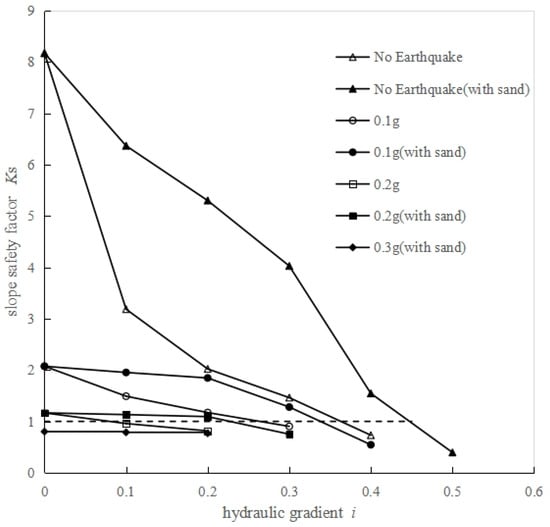
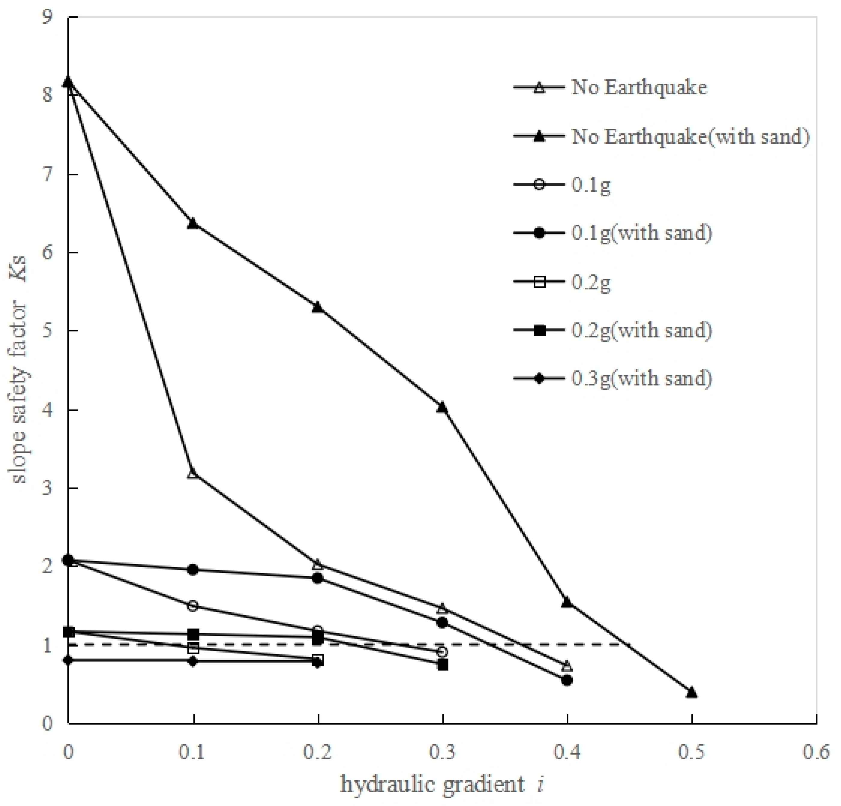
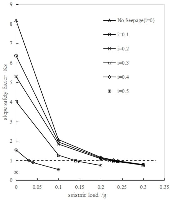
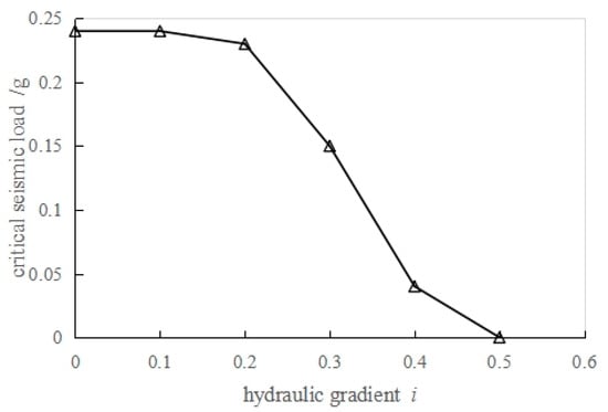
When the seismic load is 0.1 g, the slope safety factor decreases gradually with an increase in hydraulic gradient. At a hydraulic gradient of 0.4, the seepage velocity in the sandy interlayer is 6.76 × 10⁻⁷ m/s, and that in the cohesive soil layer is 1.17 × 10⁻⁷ m/s. The corresponding safety factor is 0.545 < 1.0, indicating that the slope loses stability. The same trend is observed when the seismic load is 0.2 g, but the slope loses stability at a lower hydraulic gradient of 0.3 with a safety factor of 0.751. The relationship curves between hydraulic gradient and safety factor under different seismic loads are illustrated in Figure 8, with the results for the homogeneous soil slope also plotted for comparison. Based on the data in Table 3, the relationship curves between seismic load and seabed slope safety factor Ks under different hydraulic gradients are presented in Figure 9.
Figure 8.
Relationship curve between seepage hydraulic gradient i and safety factor Ks of seabed slope with sandy interlayers under different seismic loads.
Figure 9.
Relationship curve between seismic load and safety factor Ks of seabed slope with sandy interlayers under different hydraulic gradients.
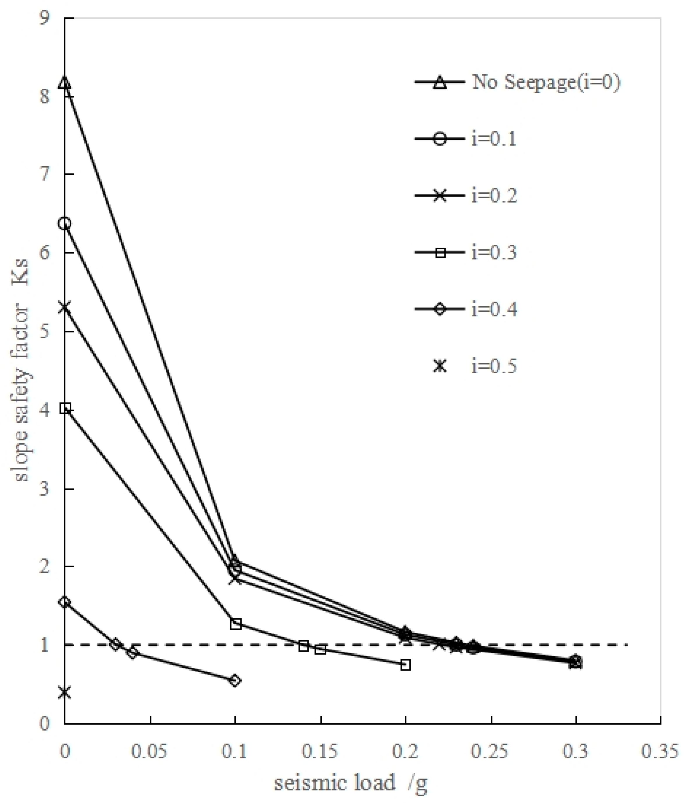
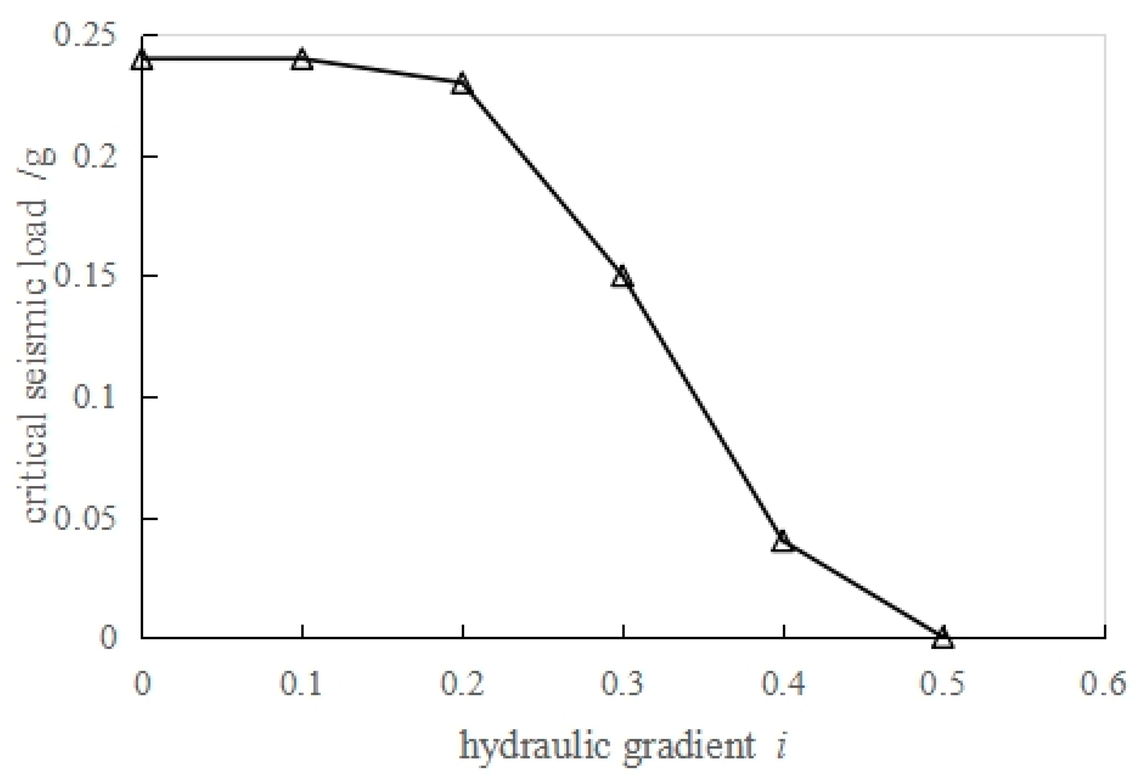
In the absence of seepage (i = 0), the slope safety factor decreases gradually with increasing seismic load. When the seismic load reaches 0.24 g, the safety factor drops to 0.988 (less than 1.0), indicating that the slope loses its stability. At a hydraulic gradient of i = 0.1, the slope also fails when the seismic load attains 0.24 g; by contrast, at i = 0.2, slope instability occurs at a reduced seismic load of 0.23 g. Notably, the three curves corresponding to i = 0, i = 0.1, and i = 0.2 almost overlap when the seismic load exceeds 0.2 g, which implies that the effect of hydraulic gradient on slope stability becomes negligible under this condition. It can thus be concluded that when the hydraulic gradient is relatively small, the sandy interlayer mitigates the impact of the hydraulic gradient on slope stability, and seismic load dominates the failure mechanism of the slope. For higher hydraulic gradients of i = 0.3, 0.4, and 0.5, the critical seismic loads triggering slope instability are 0.15 g, 0.04 g, and 0 g, respectively. The critical seismic loads corresponding to different hydraulic gradients are illustrated in Figure 10. It is evident that when the hydraulic gradient is no greater than 0.2, the variation in critical seismic load is insignificant, signifying a minimal effect of hydraulic gradient on slope stability; conversely, when the hydraulic gradient exceeds 0.2, the critical seismic load exhibits a distinct decreasing trend with increasing hydraulic gradient.
Figure 10.
Critical seismic loads corresponding to different hydraulic gradients (seabed slope with sandy interlayers).
3.3. Influence of Muddy Interlayers on Seabed Slope Stability
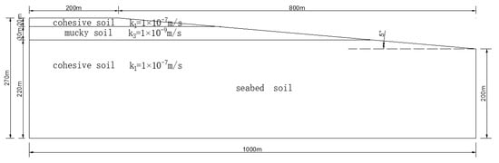
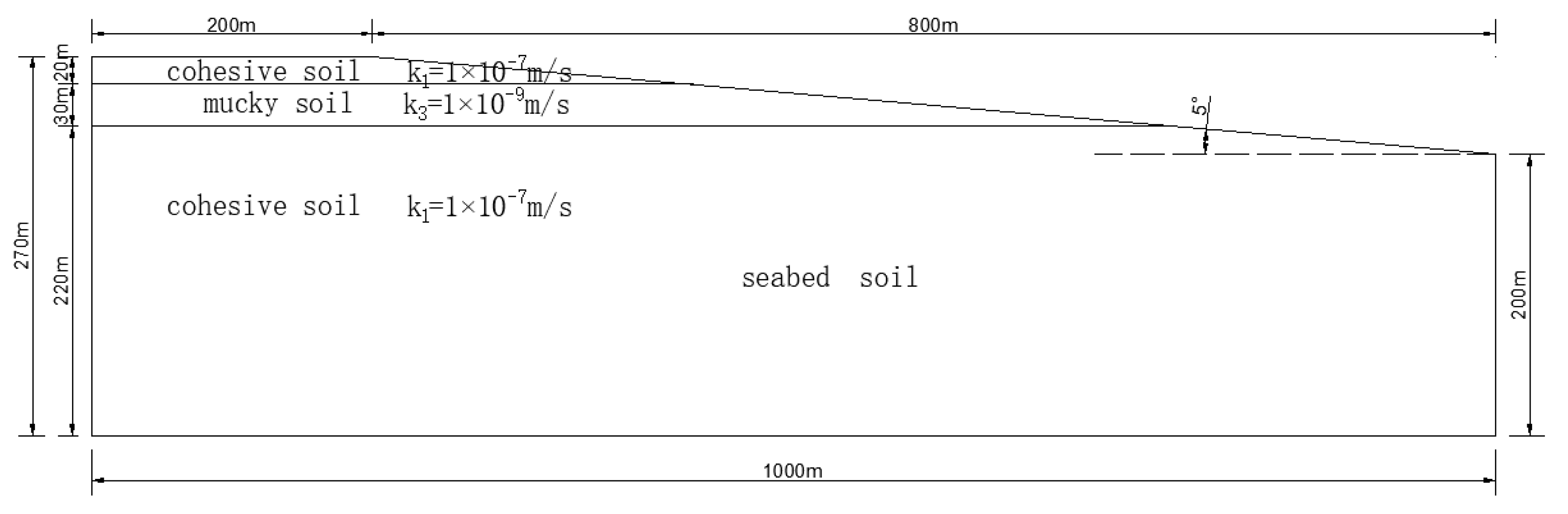
To investigate the influence of muddy interlayers in seabed soil on the stability of seabed slopes, the sandy interlayer in the previous section was replaced with mucky soil, as illustrated in Figure 11, and a stability analysis was conducted on the modified model.
Figure 11.
Schematic diagram of seabed slope with argillaceous interlayers.
In the model, the permeability coefficient of cohesive soil (k1) remains 1 × 10⁻⁷ m/s, while the permeability coefficient of mucky soil (k3) is set to 1 × 10⁻⁹ m/s. The strength parameters of mucky soil are consistent with those of cohesive soil, specifically: saturated unit weight (γsat) = 16.4 kN/m3, cohesion (c) = 10.2 kPa, and internal friction angle (Φ) = 32.5°. The specific calculation conditions and corresponding results are detailed in Table 4.
Table 4.
Calculation conditions and results for stability analysis of seabed slopes with argillaceous interlayers.
It can be observed that in the absence of seismic loading, the overall stability of the seabed slope is excellent at a hydraulic gradient of 0 (i.e., no seepage, Working Condition # 000#), with a safety factor of 8.173. This result is consistent with that of the homogeneous soil slope, since the low permeability of mucky soil exerts no influence on slope stability when seepage is absent.
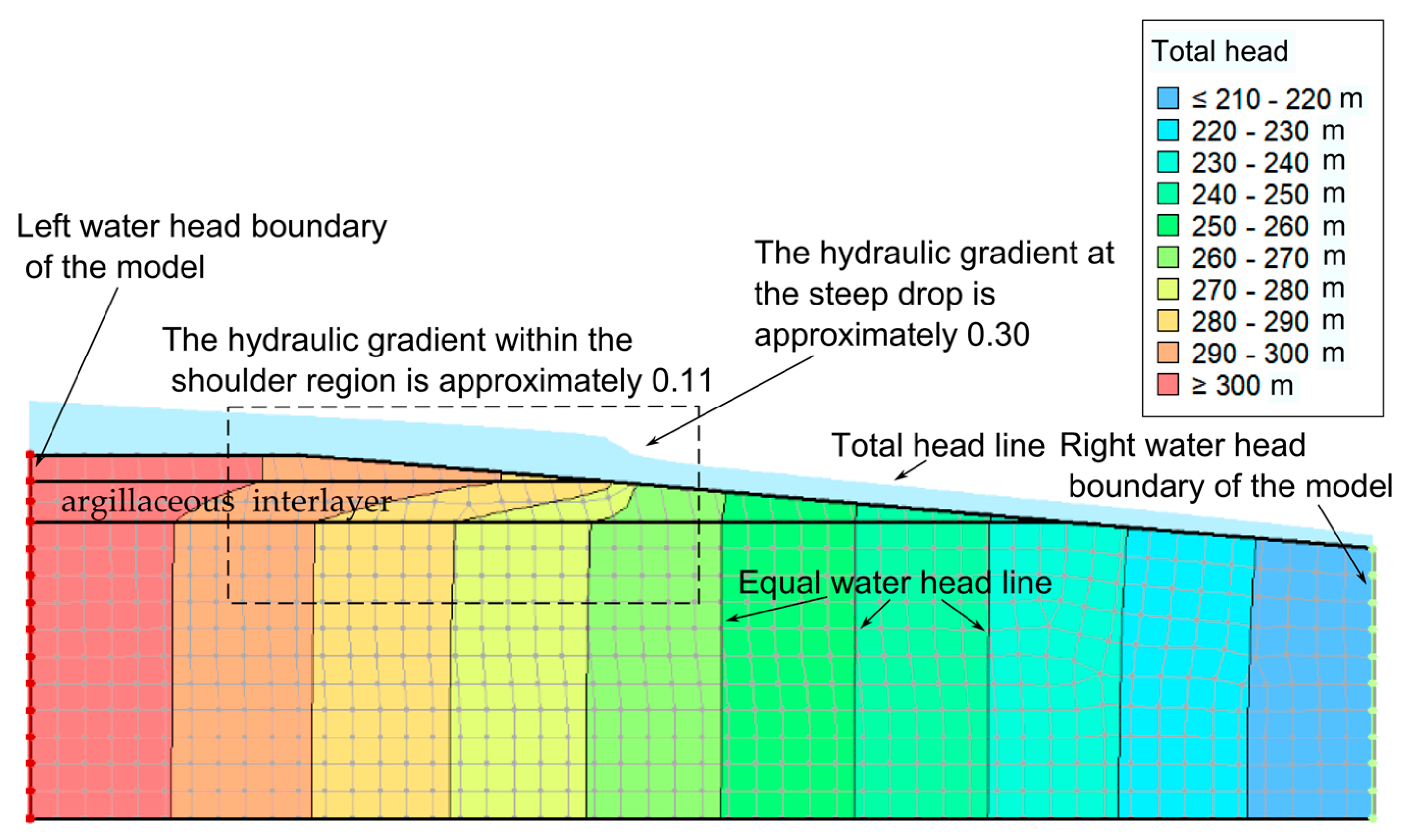
When the hydraulic gradient is 0.1 (Working Condition # 100#), seepage occurs within the seabed slope. The seepage velocity in the muddy interlayer reaches 9.10 × 10⁻¹¹ m/s, whereas that in the cohesive soil layer is 9.96 × 10⁻⁹ m/s. Under this condition, the safety factor is calculated as 2.651, which is lower than the value of 3.186 obtained for the homogeneous soil slope under Working Condition #100 (Table 2). This finding indicates that the presence of muddy interlayers reduces the stability of the seabed slope to a certain extent. The total head distribution of Working Condition #100# is presented below.
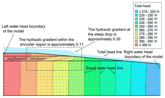
As illustrated in Figure 12, when an argillaceous interlayer is present in the seabed slope, the low permeability of the argillaceous soil leads to high flow resistance within the interlayer, resulting in a greater reduction in total head over the distribution range of the argillaceous interlayer compared with that of the homogeneous soil slope. However, since the seepage direction is nearly parallel to the argillaceous interlayer, the interlayer acts like a “parallel unit” between the upper and lower cohesive soil layers, and most of the water flows through the upper and lower cohesive soil layers. Consequently, the average hydraulic gradient within the slope shoulder zone is not significantly larger than that of the homogeneous soil slope, with a value of approximately 0.11.
Figure 12.
Total head distribution of seabed slope (Working Condition # 100#, argillaceous interlayer).
It is worth noting that there is an abrupt drop in total head at the interface between the upper cohesive soil layer and the argillaceous interlayer, where the hydraulic gradient is around 0.30. This phenomenon occurs because the seepage mesh in the software modeling only covers the soil mass but not the water body overlying the soil. As a result, in the seepage calculation of the model, water flow in the upper cohesive soil layer cannot flow into the overlying water body at the interface but is forced to flow into the argillaceous interlayer; the low permeability of the argillaceous interlayer then induces the abrupt hydraulic gradient at this location. Under the combined effects of these factors, the safety factor of the seabed slope with an argillaceous interlayer is slightly lower than that of the homogeneous soil slope.
With the progressive increase in hydraulic gradient, the seepage velocity increases accordingly, while the slope safety factor decreases continuously. When the hydraulic gradient reaches 0.4 (Working Condition # 400#), the seepage velocity within the argillaceous interlayer is 3.41 × 10⁻¹⁰ m/s, and that in the cohesive soil layer is 3.91 × 10⁻⁸ m/s. At this point, the safety factor is 0.610 < 1.0, indicating that the slope loses stability.
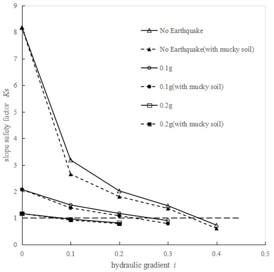
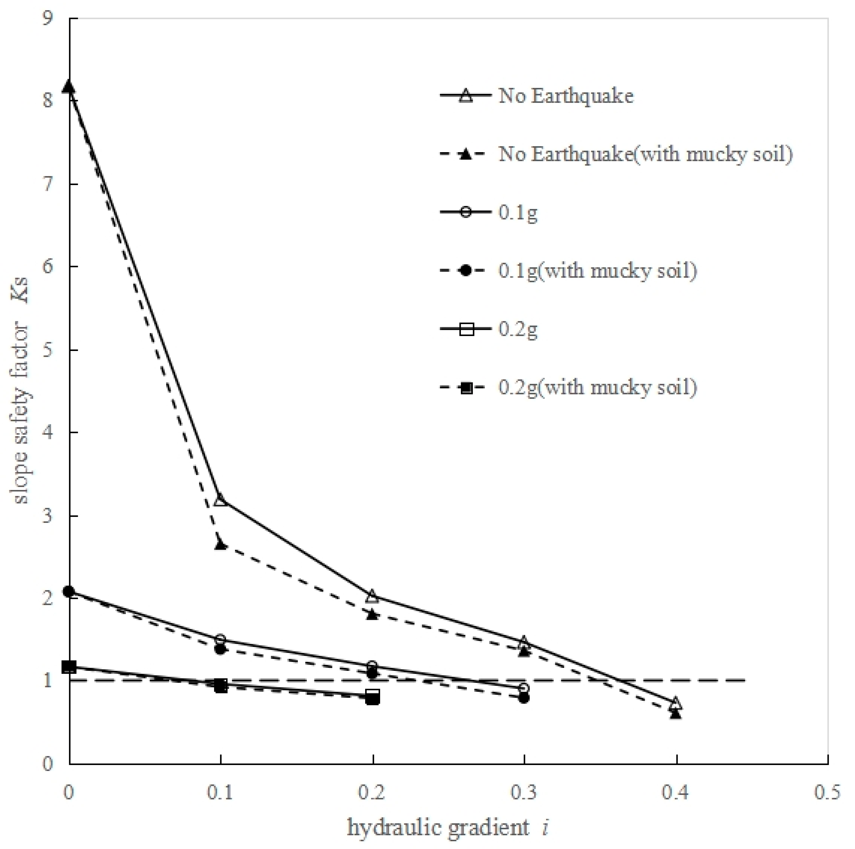
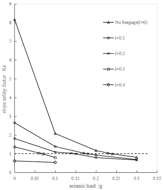
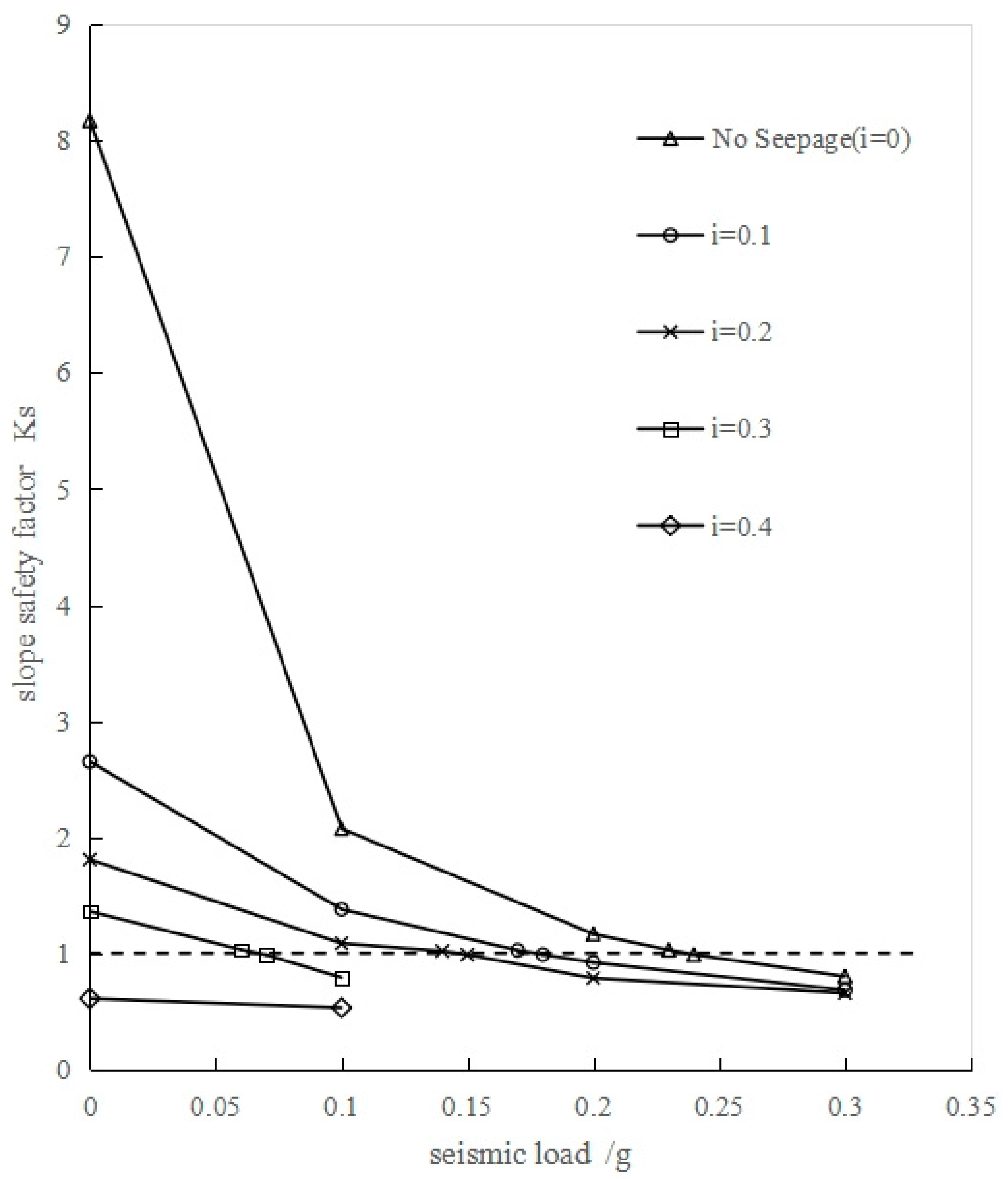
When the seismic load is 0.1 g, the slope safety factor decreases gradually with an increase in hydraulic gradient. At a hydraulic gradient of 0.3, the seepage velocity in the argillaceous interlayer is 2.61 × 10⁻¹⁰ m/s, and that in the cohesive soil layer is 2.97 × 10⁻⁸ m/s. The corresponding safety factor is 0.791 < 1.0, indicating that the slope loses stability. The same trend is observed when the seismic load is 0.2 g, but the slope loses stability at a lower hydraulic gradient of 0.1 with a safety factor of 0.921. The relationship curves between hydraulic gradient and safety factor under different seismic loads are illustrated in Figure 13, with the results for the homogeneous soil slope also plotted for comparison. Based on the data in Table 4, the relationship curves between seismic load and seabed slope safety factor Ks under different hydraulic gradients are presented in Figure 14.
Figure 13.
Relationship curve between seepage hydraulic gradient i and safety factor Ks of seabed slope with silt interlayers under different seismic loads.
Figure 14.
Relationship curve between seismic load and safety factor Ks of seabed slope with argillaceous interlayers under different hydraulic gradients.
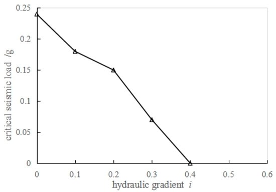
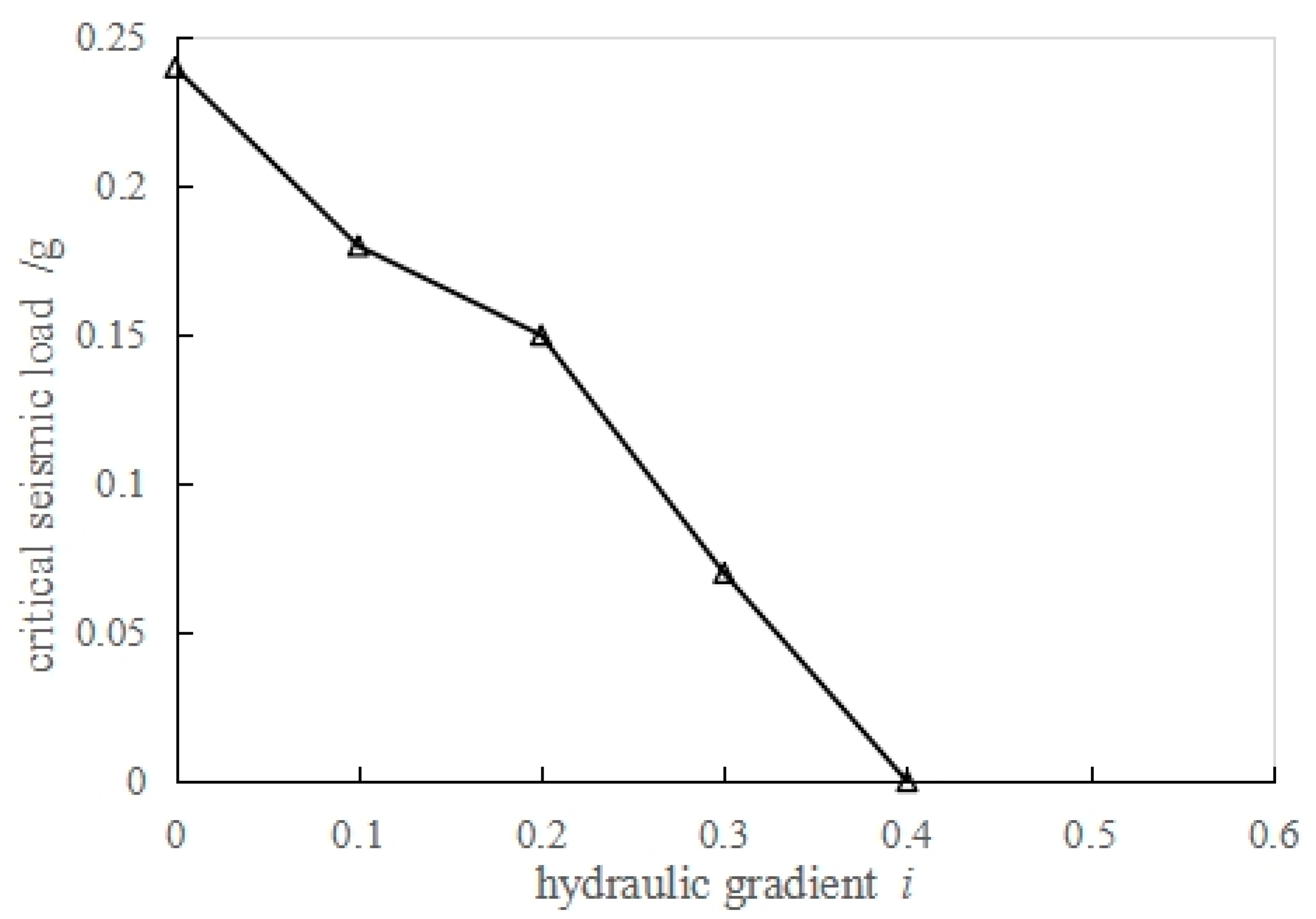
As shown in Figure 14, in the absence of seepage (i = 0), the slope safety factor decreases gradually with an increase in seismic load. When the seismic load reaches 0.24 g, the safety factor is 0.988 < 1.0, indicating that the slope loses stability. At a hydraulic gradient of i = 0.1, the slope does not lose stability until the seismic load reaches 0.18 g; similarly, at i = 0.2, slope instability occurs when the seismic load attains 0.15 g. At hydraulic gradients of 0.3 and 0.4, the seismic loads corresponding to slope instability are 0.07 g and 0 g, respectively. The critical seismic loads for different hydraulic gradients are presented in Figure 15.
Figure 15.
Critical seismic loads corresponding to different hydraulic gradients (with argillaceous interlayers).
4. Conclusions
Stability calculations were performed on seabed slopes under different combinations of seismic loads and hydraulic gradients, and the effects of sandy interlayers and argillaceous interlayers on slope stability were analyzed. The main conclusions are drawn as follows:
(1) Both seismic action and seepage exert a notable influence on the stability of seabed slopes. Seismic load plays a dominant role in governing slope stability, while seepage acts as a key triggering factor for landslides. With the progressive increase in seismic load, the impact of seepage hydraulic gradient on the slope safety factor diminishes gradually.
(2) For homogeneous seabed slopes, the critical seismic load corresponding to slope instability decreases with an increase in seepage hydraulic gradient.
(3) Under identical seismic load and hydraulic gradient conditions, seabed slopes with sandy interlayers exhibit higher stability than homogeneous soil slopes. This is attributed to the fact that sandy interlayers reduce the hydraulic gradient at the slope shoulder, leading to a decrease in seepage force. For seabed slopes with sandy interlayers, the influence of hydraulic gradient on stability is negligible when the hydraulic gradient is relatively low; when the hydraulic gradient exceeds 0.2, the critical seismic load decreases with increasing hydraulic gradient.
(4) Under the same seismic load and hydraulic gradient conditions, seabed slopes with argillaceous interlayers show slightly lower stability than homogeneous soil slopes. This is because argillaceous interlayers cause a slight increase in the hydraulic gradient at the slope shoulder, resulting in higher seepage force. Since the seepage direction is parallel to the orientation of the argillaceous interlayer, the interlayer acts like a “parallel unit” between the upper and lower cohesive soil layers. As a result, the average hydraulic gradient within the interlayer distribution zone does not differ significantly from that of the homogeneous soil slope. Except for the slightly reduced safety factor, the stability characteristics of slopes with argillaceous interlayers are consistent with those of homogeneous soil slopes.
Author Contributions
Conceptualization, X.Q. and J.X.; methodology, X.Q. and P.L.; software, P.L.; validation, X.Q., Y.Y., and J.X.; formal analysis, P.L. and X.Q.; investigation, P.L. and X.Q.; resources, J.X., S.B., and J.Z.; data curation, P.L. and X.Q.; writing—original draft preparation, P.L. and X.Q.; writing—review and editing, X.Q., P.L., Y.Y., and J.X.; visualization, P.L.; supervision, J.X., S.B., and J.Z.; project administration, J.X. and X.Q.; funding acquisition, J.X., X.Q., and Y.Y. All authors have read and agreed to the published version of the manuscript.
Funding
This research was funded by the National Natural Science Foundation of China (Grant Nos. 42350710199, 42106198); the Guangdong Provincial Key Discipline Research Capacity Enhancement Initiative (Grant Nos. 2024ZDJS060, 2024ZDJS053); the Guangdong Provincial Key Special Programmes in Priority Areas for Higher Education Institutions (Serving the “Hundreds- Thousands-Ten Thousands Project”) (2025ZDZX4054); and the Research Innovation Fund of Tianjin Research Institute for Water Transport Engineering, Ministry of Transport, China (Grant No. TKS20250704).
Institutional Review Board Statement
Not applicable.
Informed Consent Statement
Not applicable.
Data Availability Statement
The original contributions presented in this study are included in the article. Further inquiries can be directed to the corresponding author.
Conflicts of Interest
The authors declare no conflicts of interest.
References
- Wang, X.; Maselli, V.; Flessati, L.; Wang, H.; Sun, Z.; Wang, Q.; Chen, J.; Li, Q.; Alberti, S.; Kienast, M.; et al. Preconditioning of sediment failure by astronomically paced weak-layer deposition. Nat. Commun. 2025, 16, 7244. [Google Scholar] [CrossRef] [Scilit] [PubMed]
- Dong, Y.; Cui, L.; Zhang, X. Multiple-GPU parallelization of three-dimensional material point method based on single-root complex. Int. J. Numer. Methods Eng. 2022, 123, 1481–1504. [Google Scholar] [CrossRef] [Scilit]
- Shi, H.; Chu, H.; Gao, X. A review of submarine slope stability studies and methods. Mar. Geol. Front. 2013, 29, 42–45+59. [Google Scholar]
- Hicks, M.A.; Nuttall, J.D.; Chen, J. Influence of heterogeneity on 3D slope reliability and failure consequence. Comput. Geotech. 2014, 61, 198–208. [Google Scholar] [CrossRef] [Scilit]
- Wang, Y.; Wang, Y.Y.; Gao, M.; Zhang, L. Study on slope stability of deep-sea energy soil gas reservoir. J. Shandong Univ. Sci. Technol. (Nat. Sci.) 2024, 43, 32–40. [Google Scholar]
- Liu, H.; Zhang, M.; Jia, Y.; Wang, X. Analysis of seabed stability under wave loading. Rock Soil Mech. 2006, 27, 986–990. [Google Scholar]
- Dong, S.J. Mechanism of the wave-induced seabed instability in the vicinity of a breakwater: A review. Ocean Eng. 2001, 28, 537–570. [Google Scholar] [CrossRef] [Scilit]
- Ai, F.; Frster, A.; Stegmann, S.; Kopf, A. Geotechnical Characteristics and Slope Stability Analysis on the Deeper Slope of the Ligurian Margin, Southern France; Springer International Publishing: Berlin/Heidelberg, Germany, 2014. [Google Scholar]
- Dugan, B.; Flemings, P.B. Overpressure and fluid flow in the New Jersey continental slope: Implications for slope failure and cold seeps. Science 2000, 289, 288–291. [Google Scholar] [CrossRef] [Scilit] [PubMed]
- Kooi, H. Competition between topography- and compaction-driven flow in a confined aquifer: Some analytical results. Hydrogeol. J. 1999, 7, 245–250. [Google Scholar] [CrossRef] [Scilit]
- Frederick, J.M.; Buffett, B.A. Effects of submarine groundwater discharge on the present-day extent of relict submarine permafrost and gas hydrate stability on the Beaufort Sea continental shelf. J. Geophys. Res. Earth Surf. 2015, 120, 417–432. [Google Scholar] [CrossRef] [Scilit]
- Witt, C.; Kopf, A. Submarine Groundwater Discharge in the Nice Airport Landslide Area. J. Mar. Sci. Eng. 2025, 13, 909. [Google Scholar] [CrossRef] [Scilit]
- Paull, C.K.; Dallimore, S.R.; Caress, D.W.; Gwiazda, R.; Lundsten, E.; Anderson, K.; Melling, H.; Jin, Y.K.; Duchesne, M.J.; Kang, S.-G.; et al. A 100-km wide slump along the upper slope of the Canadian Arctic was likely preconditioned for failure by brackish pore water flushing. Mar. Geol. 2021, 435, 106453. [Google Scholar] [CrossRef] [Scilit]
- Dai, S.; Han, B.; Huang, G.X.; Gu, X.; Jian, L.; Liu, S. Failure mode of monopile foundation for offshore wind turbine in soft clay under complex loads. Mar. Georesources Geotechnol. 2022, 40, 14–25. [Google Scholar] [CrossRef] [Scilit]
- Bray, J.D.; Travasarou, T. Pseudostatic coefficient for use in simplified seismic slope stability evaluation. J. Geotech. Geoenviron. Eng. 2009, 135, 1336–1340. [Google Scholar] [CrossRef] [Scilit]

Disclaimer/Publisher’s Note: The statements, opinions and data contained in all publications are solely those of the individual author(s) and contributor(s) and not of MDPI and/or the editor(s). MDPI and/or the editor(s) disclaim responsibility for any injury to people or property resulting from any ideas, methods, instructions or products referred to in the content. |
© 2026 by the authors. Licensee MDPI, Basel, Switzerland. This article is an open access article distributed under the terms and conditions of the Creative Commons Attribution (CC BY) license.