


Abstract
This study investigates the combustion and emission characteristics of a marine low-speed two-stroke engine using diesel-ignited ammonia dual direct injection. Using a validated 3D CFD model, the impact of ammonia blending ratios (Ra) was systematically explored. Results indicate that the strategy of shifting energy from early diesel injection to late ammonia injection physically repositions the combustion phasing. Rather than ammonia delaying the heat release, this late injection strategy avoids the overly early combustion observed at low ammonia concentrations, thereby lowering peak in-cylinder temperatures while maintaining robust work extraction. Consequently, indicated power at the N90 condition increases by 3.5% (to 1689 kW) over the diesel baseline, with a minimum EISFC of 165.5 g/kWh. High-ratio ammonia blending achieves deep decarbonization: at N90, peak CO and soot emissions are reduced by over 90% and 95%, respectively. Additionally, NOx emissions decrease by approximately 70% at N90 compared to the N20 peak, attributed to the thermal DeNOx mechanism. However, the low-temperature environment introduces trade-offs, leading to increased ammonia slip (4 ppm at N90) and elevated N2O emissions (peaking at N70). These findings clarify the mechanisms governing ammonia combustion and provide theoretical support for optimizing zero-carbon marine propulsion systems.
1. Introduction
Industrialization has led to a growing demand for fossil fuels and a consequent rise in CO2 emissions, intensifying the global greenhouse effect and climate warming. Reliance on fossil fuels not only contributes to environmental pollution but also constrains sustainable social development [1]. Global trade and transportation are major sources of carbon emissions, with the shipping industry responsible for 80–90% of international cargo transport, serving as a critical driver of global economic growth. However, it is also one of the primary emitters of greenhouse gases, accounting for approximately 6% of annual global CO2 emissions [2], thereby playing a significant role in global warming and climate change [3].
Under the strategic goals of “carbon peaking” and “carbon neutrality,” promoting and developing clean as well as low- or zero-carbon fuels in the internal combustion engine (ICE) sector has become particularly important. This approach represents one of the most effective pathways to reduce carbon emissions and mitigate global warming [4]. As a zero-carbon fuel, ammonia offers a promising solution for achieving these targets and supports the International Maritime Organization’s 2050 greenhouse gas reduction objectives [5]. Indeed, extensive research has been conducted on the performance of ammonia-fueled engines [6]. Liu et al. [7] developed an engine model with a maximum compression ratio of 24:1, integrating a detailed chemical reaction mechanism to realize direct injection of ammonia fuel in a compression ignition engine, assisted by a spark plug ignition system. The results demonstrated the feasibility of converting a compression ignition engine into a spark-assisted ammonia-fueled engine, verifying the applicability of ammonia fuel in low-speed two-stroke engines.
In 2018, Lee et al. [8] proposed a method for operating engines with pure ammonia by injecting an ammonia–air mixture at the end of the compression stroke to achieve the pressure and temperature necessary for ignition. The authors investigated the operating conditions and performed simulation analyses; however, successful operation without an additional ignition promoter was not achieved. Due to ammonia’s poor combustion characteristics, such as high auto-ignition temperature, low flame speed, narrow flammability limits, and high latent heat of vaporization [9], pure ammonia combustion is attainable only at high compression ratios [10]. These intrinsic properties limit the overall efficiency of ammonia as a fuel. Moreover, ammonia combustion generates a considerable amount of nitrogen oxides (NOx), and the resulting nitrous oxide (N2O) is an even more potent greenhouse gas than carbon dioxide [11]. These challenges cast doubt on the feasibility of ammonia as a sole fuel; thus, blending ammonia with other fuels has emerged as a promising strategy to overcome these limitations.
Ammonia/diesel dual fuel combustion is a feasible approach for utilizing ammonia in internal combustion engines. The application of ammonia in compression ignition (CI) engines can be traced back to the 1960s, when Gray J.T. et al. [12] first investigated ammonia/diesel dual fuel engines and explored various methods to achieve stable ammonia combustion. Their findings revealed that for optimal utilization in CI engines, ammonia should be injected into the cylinder at an approximately 40° crank angle before the end of diesel injection. Stable combustion under compression ignition was achieved even at a compression ratio as low as 15.2. Diesel, as the dominant fuel for CI engines, has been widely used in subsequent dual-fuel configurations. Reiter A.J. et al. [13,14] modified a 4.5 L engine with a compression ratio of 17 to operate as an ammonia/diesel dual-fuel engine, introducing ammonia through the intake manifold and injecting diesel directly into the cylinder. Their experiments investigated the combustion and emission characteristics of ammonia/diesel mixtures. The results indicated that the engine could operate successfully with up to 95% ammonia energy substitution. When the ammonia energy share ranged between 40% and 80%, the engine exhibited the best specific fuel consumption (SFC). Regarding emissions, CO2 emissions decreased monotonically with increasing ammonia substitution. When the ammonia energy fraction did not exceed 60%, NOx emissions were lower than those of pure diesel operation; however, further increases in ammonia substitution led to a significant rise in NOx emissions. Reiter et al. [15] further tested an improved ammonia/diesel dual fuel engine, in which ammonia was injected into the intake port and diesel was directly injected into the cylinder. The results demonstrated that ammonia could be successfully combusted in modern diesel engines across a wide range of engine speeds and loads, achieving the same torque output at different ammonia substitution ratios. Stable operation was maintained even with up to 95% ammonia energy contribution, and optimal fuel economy was achieved at substitution levels between 40% and 80%. Niels et al. [16] from Denmark employed a dual-cylinder diesel engine operating under compression ignition, with n-heptane as a pilot fuel to ignite a premixed ammonia air charge. Their study found that this pilot-assisted ignition method enabled the ammonia energy fraction to exceed 90%, increasing overall combustion efficiency (defined as the ratio of released heat to the total fuel energy input, accounting for losses from unburned species) from 81% to 90% under a constant air fuel equivalence ratio. However, higher ammonia energy fractions also resulted in increased ammonia slip and elevated NOx emissions.
The adoption of ammonia/diesel dual-fuel engines can effectively advance the shipping industry’s progress toward the “carbon peaking and carbon neutrality” goals [17,18]. Zhou et al. [19] compared the overall performance of a commercial marine engine under low-pressure and high-pressure ammonia injection modes. The results indicated that at similar diesel substitution ratios (approximately 98–99%), both modes achieved thermal efficiencies exceeding 50%. Under optimized combustion conditions, the premixed combustion mode improved thermal efficiency by 5.1%, but NOx emissions were 140.6% higher than those of the conventional diesel engine. In contrast, the high-pressure injection mode achieved comparable thermal efficiency to the baseline engine while reducing NOx emissions to 47% of the original level. Niki et al. [20,21] modified the structure of a four-stroke high-speed engine to enable ammonia port injection and subsequently conducted a series of studies on the combustion and emission characteristics of ammonia/diesel dual fuel operation. The fundamental performance results revealed that, with increasing ammonia injection quantity, both the in-cylinder compression pressure and peak pressure decreased, while the ignition delay time was prolonged.
Based on previous studies, significant progress has been achieved in the research of ammonia/diesel dual fuel engines; however, studies on large-bore, low-speed two-stroke direct injection ammonia engines for marine applications remain scarce. These engines are characterized by adjustable ammonia injection timing and low rotational speeds, which provide sufficient time for complete ammonia combustion. The large combustion chamber volume enables structural modifications, while the long stroke and high compression ratio further promote faster combustion and higher thermal efficiency. In this study, experimental data from a marine two-stroke engine were used to validate a three-dimensional numerical model, which was subsequently employed to investigate the effects of ammonia/diesel injection strategies on engine performance and emissions. This work bridges the gap in domestic research on low-speed two-stroke direct injection ammonia engines, advances the application of ammonia in marine propulsion, and contributes significantly to achieving carbon neutrality and zero emission objectives.
2. Materials and Methods
2.1. Experimental Test Bench Description
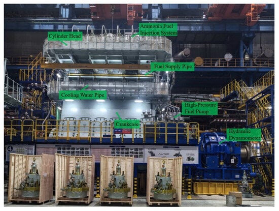
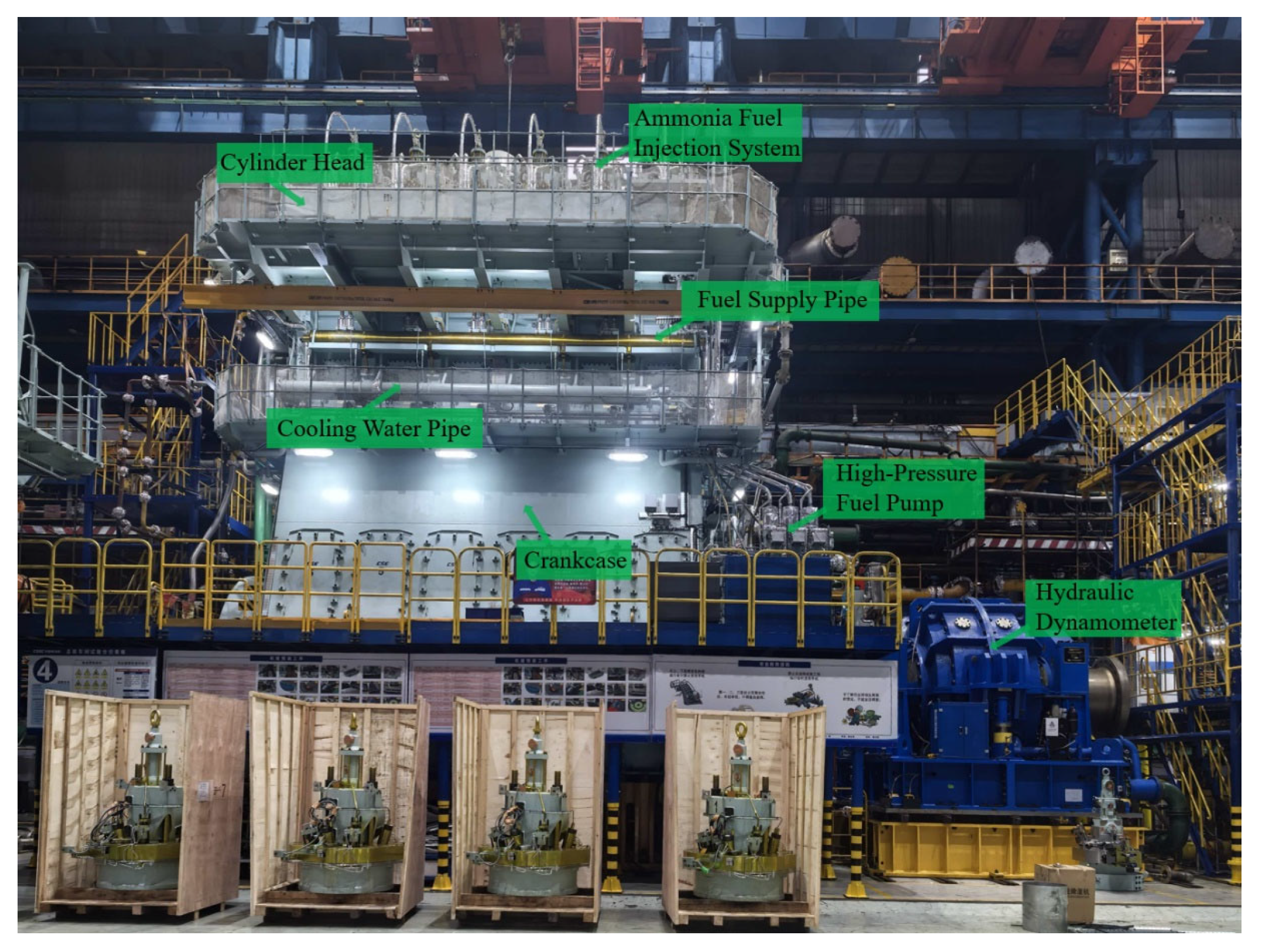
In this study, a WinGD 6X72-A ammonia/fueled engine, manufactured by CSSC Engine Co., Ltd., Qingdao, China, was selected as the research object. An ammonia fuel supply system was established to enable experimental investigations on the ammonia-fueled engine. Figure 1 presents a schematic diagram of the experimental test bench system, and the main technical specifications of the engine are listed in Table 1.
Figure 1.
Test Bench System.
Table 1.
Main structural parameters of X72DF-A.
An Hydraulic dynamometer (Xiangyi Power Testing Instrument Co., Ltd., Changsha, China) was connected to the flywheel end of the engine to provide the required load. The test system mainly consisted of an Diesel/Ammonia fuel flow meter (Emerson Electric Co., Boulder, CO, USA), a smoke meter (AVL List GmbH, Graz, Austria), a combustion analysis system, an Endress + Hauser gas flow meter (Endress+Hauser, Reinach, Switzerland), and in-cylinder pressure sensors (Kistler Group, Winterthur, Switzerland), among other instruments. The primary measurement equipment employed on the test bench, along with their corresponding measurement uncertainties and accuracies, is listed in Table 2.
Table 2.
Technical Indicators of Main Testing Equipment.
Table 3 shows the experimental operating conditions, including ammonia energy fraction, start of diesel injection (SODI), end of diesel injection (EODI), and flow rates of diesel and ammonia. To comprehensively evaluate the proposed ammonia combustion strategy across the representative marine operational envelope, two distinct operating points were selected: 25% load (42 rpm) and 75% load (60.6 rpm). These conditions were strictly derived from the theoretical fixed-pitch propeller curve (cubic law) typical for low-speed two-stroke engines. The 25% load case serves as a critical baseline for ‘Slow Steaming’ to assess ignition stability under lower in-cylinder temperatures, while the 75% load case corresponds to the ‘Normal Continuous Rating’ (NCR), representing the dominant steady-state cruising mode. Consequently, these selected points effectively cover the engine’s primary performance characteristics from low-load stability to high-load efficiency.
Table 3.
Validation conditions.
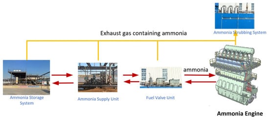
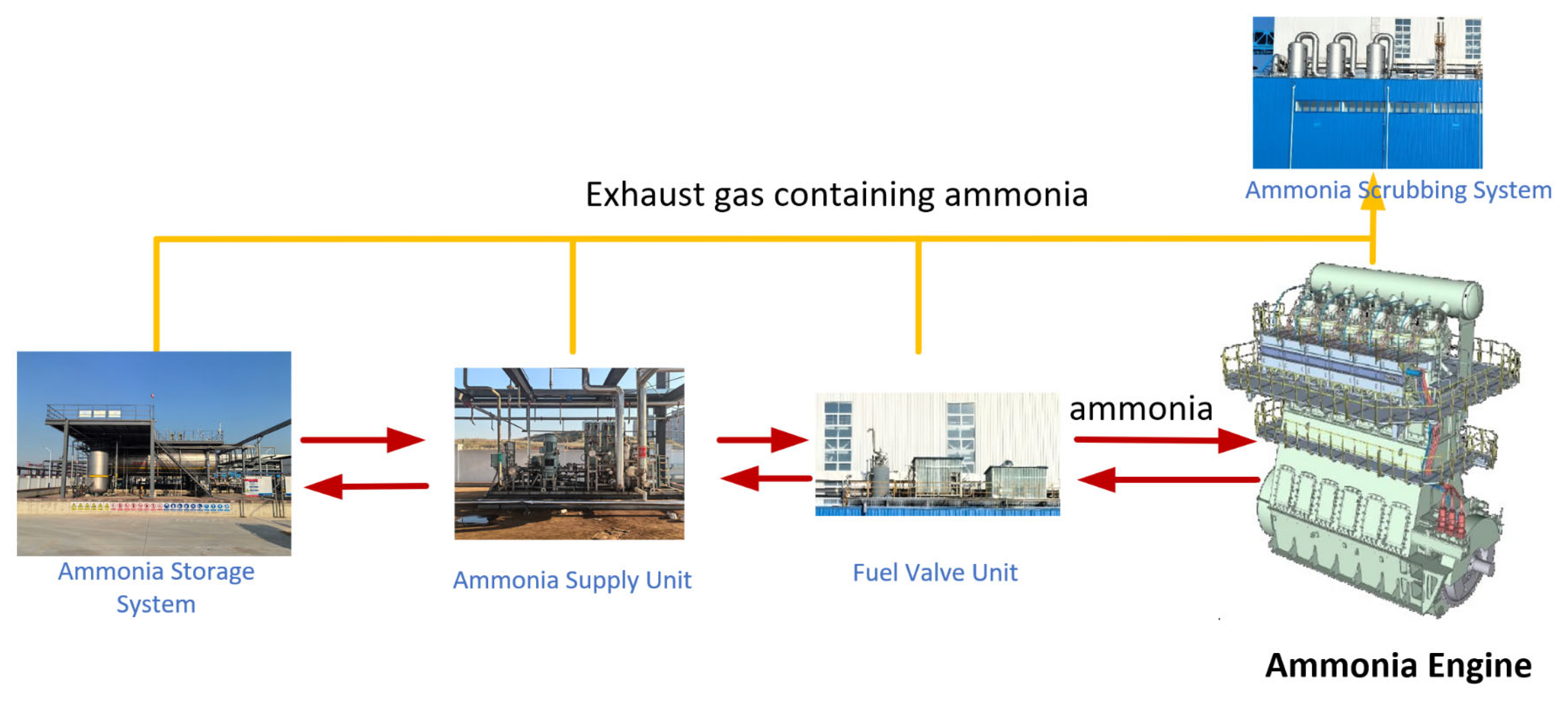
The ammonia-fueled engine test bench comprised six main subsystems: an ammonia storage system, an ammonia fuel supply system, an ammonia valve control module, a water circulation system, a nitrogen system (used for purging residual ammonia from fuel lines and providing sealing gas), an ammonia exhaust treatment system, and the engine itself. The ammonia fuel supply system delivered liquid ammonia to the engine at a pressure of 85 bar and a temperature range of 25–45 °C, as illustrated in Figure 2. Other technical parameters of the system are listed in Table 4.
Figure 2.
Schematic Diagram of the Ammonia Fuel Supply System.
Table 4.
Parameters of the Ammonia Fuel Supply System.
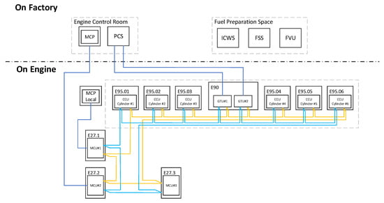
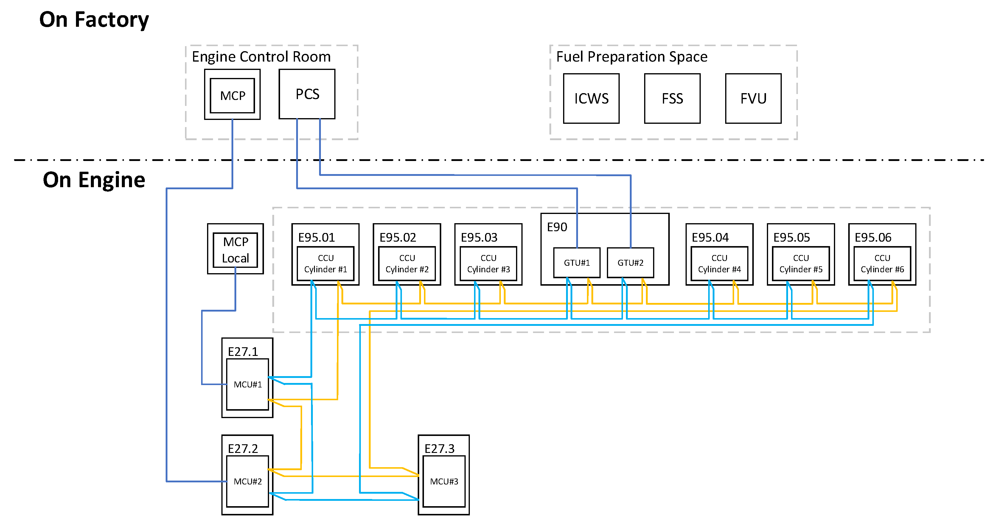
As shown in Figure 3, the control system of the ammonia-fueled engine test bench is divided into two sections according to installation location: one in the workshop and the other mounted on the engine.
Figure 3.
Ammonia fuel engine control system.
The remote control system (PCS) and the engine MCP control panel are installed in the centralized control room of the workshop, providing functions such as engine control, safety protection, and system parameter configuration. The control systems for the fuel supply unit, fuel valve unit, and cooling water unit are installed adjacent to the centralized control room, enabling real-time control of the fuel delivery process.
On the engine itself, several modules are installed, including the Local Operating Panel (LOP), the Main Control Unit (MCU), the Cylinder Control Unit (CCU), and the Gateway Transmission Unit (GTU). Communication between these modules primarily uses an Ethernet network, while CAN communication is adopted between the GTU and PCS, as well as between the MCU and MCP.
The main difference between the control system of the ammonia-fueled engine and that of a conventional fuel engine lies in the addition of the E27.3 control cabinet (Qingdao China CSSC Engine Co., Ltd., Qingdao, China). This controller is responsible for managing the ammonia-related sensors and actuators, as well as providing monitoring and safety protection functions in ammonia operation mode. Furthermore, the CCU unit incorporates additional functions related to ammonia fuel injection control, ammonia distribution valve control, and ammonia leakage monitoring, ensuring safe and precise operation under ammonia combustion conditions.
2.2. Establish Simulation Model
The three-dimensional Computational Fluid Dynamics (CFD) simulations were conducted using the commercial software CONVERGE v3.0. The object of this simulation study is a WinGD 6X72-A ammonia-fueled engine (Qingdao China CSSC Engine Co., Ltd., Qingdao, China), whose main specifications are listed in Table 1.
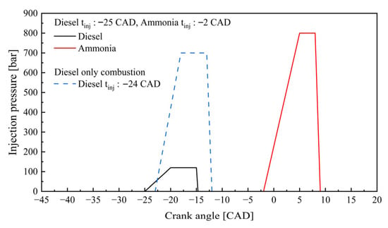
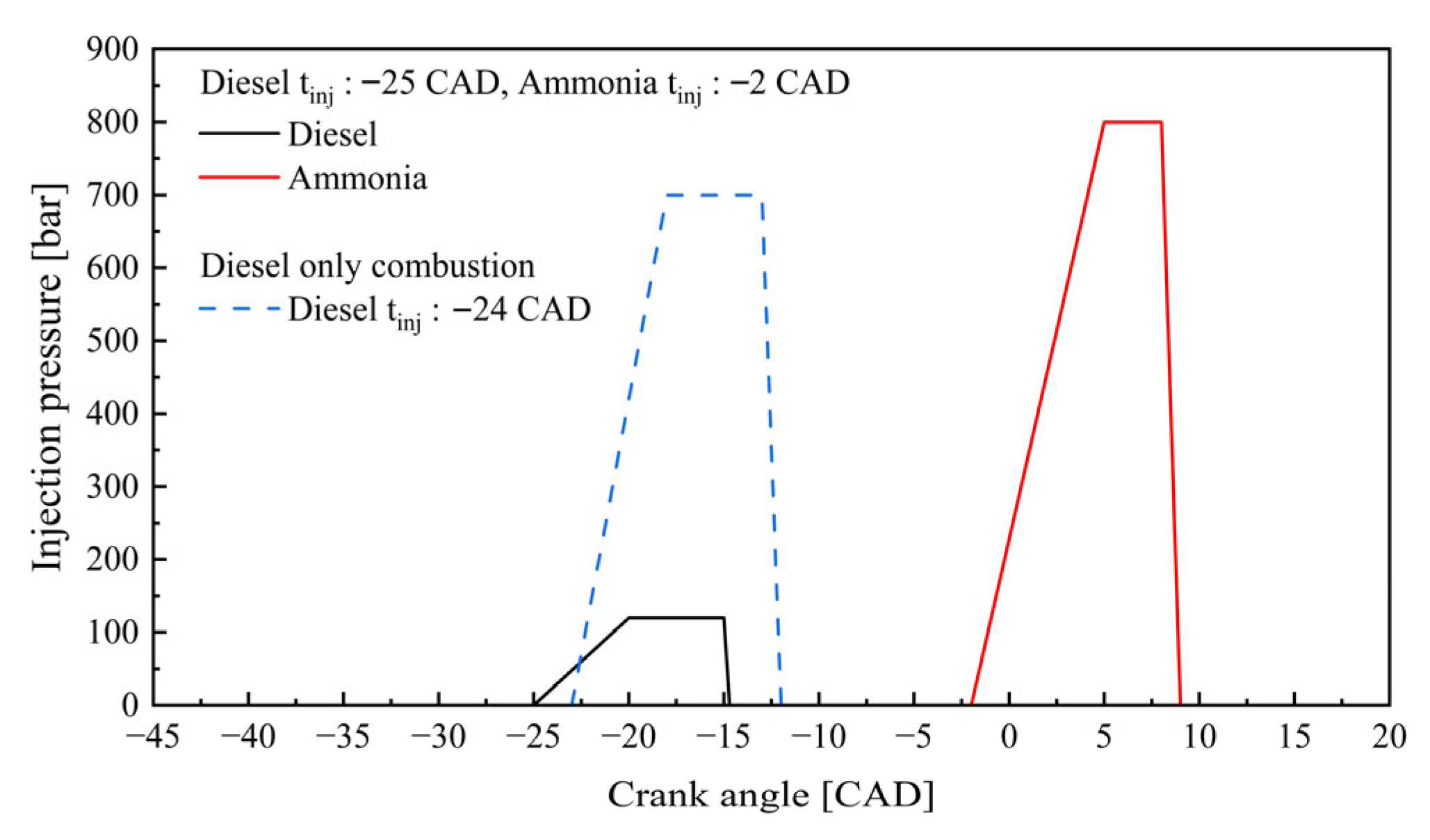
Figure 4 illustrates the representative injection pressure profiles employed for all dual-fuel cases in this study. To strictly isolate the effects of the ammonia energy fraction (Ra), a consistent injection strategy was maintained across all simulations. Specifically, the diesel pilot injection is timed at −25 CAD ATDC with a peak pressure of 120 bar to ensure stable ignition, while the main ammonia injection is triggered at Top Dead Center (0 CAD) with a significantly higher pressure of 800 bar to promote atomization. Variations in fuel mass for different Ra were achieved by adjusting the nozzle flow area while adhering to these fixed pressure traces.
Figure 4.
Injection pressure shape during simulation for ammonia-direct-injection combustion and diesel-only combustion.
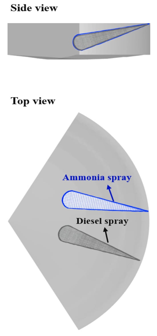
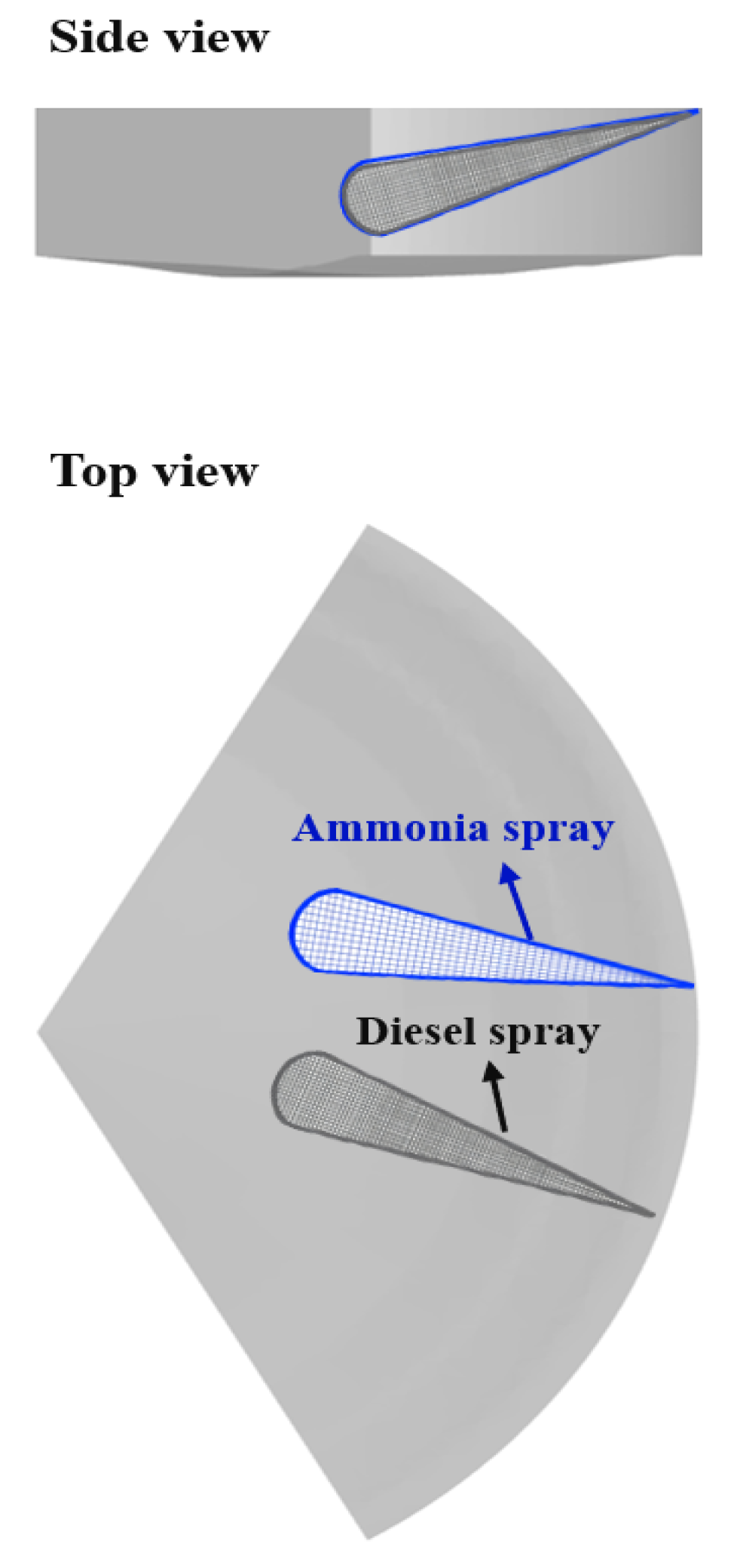
Based on the structural parameters of the engine presented in Table 1, to better observe the injection direction and angle, a 1/3 sector model of the engine was established. The mesh configuration of the model is shown in Figure 5, and the sub-models adopted during model construction are listed in Table 5.
Figure 5.
Schematic Diagram of the Model.
Table 5.
Selection of simulation sub-model.
A fixed diesel injection timing of −25 CAD BTDC was adopted to guarantee stable ignition at high ammonia ratios (N80-N90). Although this timing is advanced for the pure diesel case (N0) compared to commercial calibration, maintaining a constant injection strategy allows for isolating the physicochemical effects of the ammonia energy fraction (Ra). Therefore, the N0 case represents a comparative baseline under identical control constraints rather than optimized commercial performance [22].
The SAGE combustion model [27] was selected to simulate the in-cylinder ignition and subsequent flame propagation processes. The combustion simulation was coupled with a reduced ammonia/diesel reaction mechanism, derived from Sun [31], which consists of 333 species and 1934 elementary reactions. The initial conditions applied in the simulation are summarized in Table 6. In this study, the simulation domain was limited to the period from intake valve closing (IVC) to exhaust valve opening (EVO). The simulations involve two fuels, ammonia and diesel, and their physicochemical properties are summarized in Table 7. It can be observed that the ignition energy of ammonia is significantly higher than that of diesel. From a theoretical standpoint, employing diesel as an ignition source to initiate and enhance the combustion of ammonia is therefore feasible.
Table 6.
Boundary parameters.
Table 7.
Comparison of fuel properties.
2.3. Operating Conditions
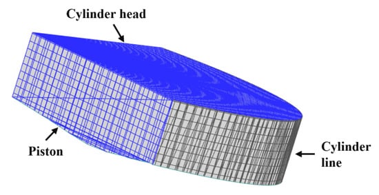
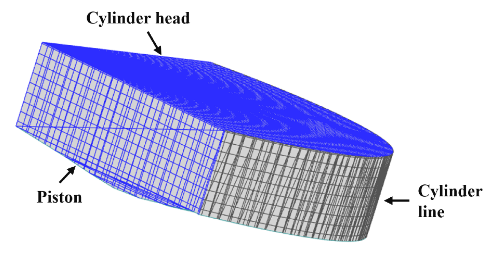
In the simulation study, an in-cylinder direct injection strategy for the ammonia/diesel blend was adopted. As shown in Figure 5, the fuel supply and injection system of the original engine were modified as necessary to accommodate ammonia fuel. Figure 6 illustrates the computational mesh generation. Based on the research objectives, a simulation plan was developed, as summarized in Table 8.
Figure 6.
Combustion Chamber Model.
Table 8.
Simulation research scheme.
Under the engine’s rated load, ten different ammonia/diesel blending ratios were defined. For example, N30 corresponds to an ammonia-to-diesel calorific energy ratio of 3:7. The total calorific value of the ammonia/diesel mixture was maintained constant as the ammonia fraction increased. During injection, the injector parameters and injection pressure were kept constant, while the injection quantity and duration were adjusted accordingly.
The blending ratio is defined as the fraction of heat released by ammonia combustion relative to the total calorific value of the ammonia/diesel mixture. The Equivalent Indicated Specific Fuel Consumption (EISFC) represents the total calorific value of the consumed fuel converted to the equivalent diesel consumption per unit of indicated power. The specific calculation formula is as follows:
where is the ammonia blending ratio; and are the masses of ammonia and diesel, respectively; is the lower heating value (LHV) of ammonia, 18.8 MJ/kg; is the lower heating value of diesel used to calculate the diesel equivalent specific fuel consumption, 42.5 MJ/kg; is the indicated power.
2.4. Simulation Model Validation
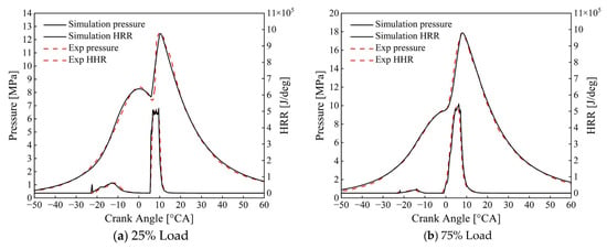
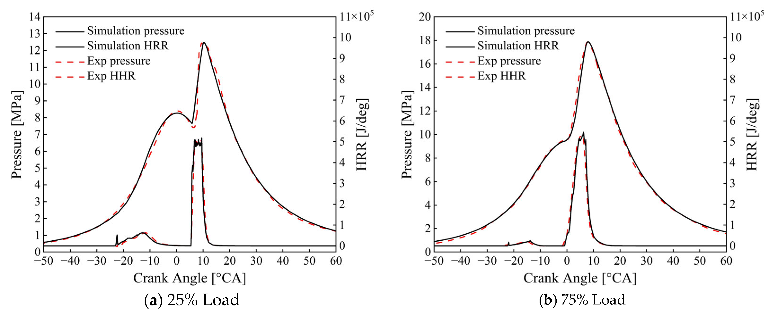
Figure 7 compares the experimental and simulated values of engine performance and emissions. The key parameters include cylinder pressure and heat release rate at different loads. The results indicate a good agreement between the simulated and experimental data. The discrepancies between measured and simulated values are within acceptable limits and have a negligible impact on subsequent analyses. Consequently, the validated model is considered reliable for supporting further studies.
Figure 7.
Model validation.
3. Results and Analysis
3.1. Effect of Engine Combustion Performance
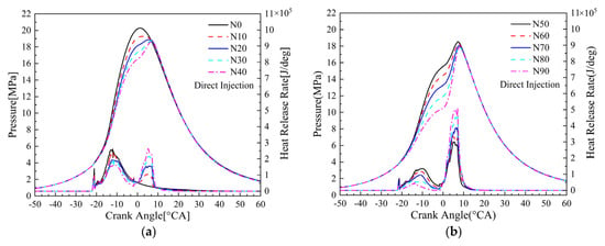
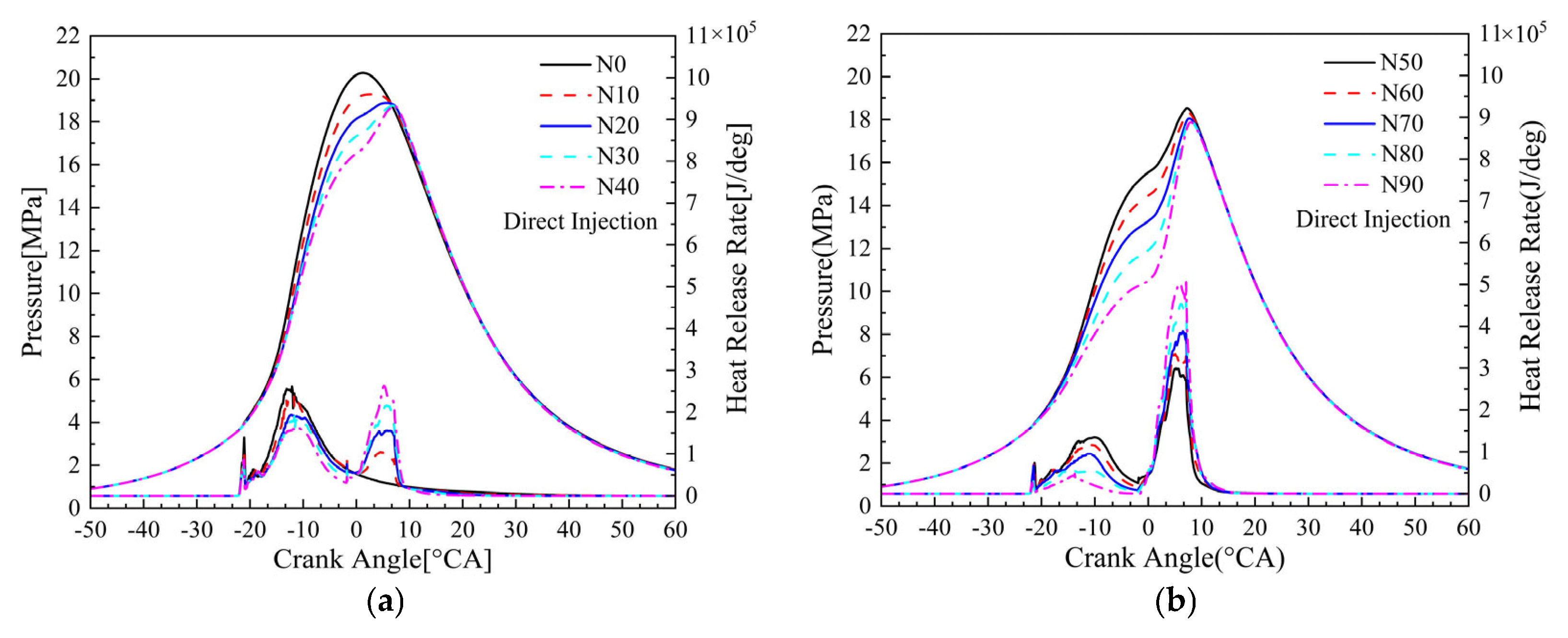
Figure 8 illustrates the in-cylinder pressure and Heat Release Rate (HRR) profiles across varying ammonia blending ratios (N0–N90). Regarding in-cylinder pressure, Pmax exhibits a monotonic decrease as the ammonia fraction increases. In the low-blending regime (Figure 8a), Pmax declines from 20.3 MPa (pure diesel, N0) to 18.3 MPa (N40), a reduction of 2.0 MPa. This trend intensifies in the high-blending regime (Figure 8b), where the peak pressure at N90 falls to approximately 17.0 MPa, representing a cumulative reduction of 3.3 MPa relative to N0. This reduction in peak pressure is primarily attributed to the shifted heat release phasing dictated by the injection schedule. Since the main ammonia injection occurs later (−2 to 9 CAD) compared to the pilot diesel, the bulk of the combustion energy is released during the expansion stroke, physically limiting the pressure rise. Regarding HRR, ammonia addition results in marked peak attenuation and phase retardation. The peak heat release rate diminishes by approximately 22%, dropping from 5.8 J/°CA at N0 to 4.5 J/°CA at N90. Concurrently, the combustion phasing shifts significantly; the main heat release peak moves from −8° CA (N0) to 6° CA (N90). This retardation is fundamentally driven by the shift in the energy supply schedule from the early diesel injection (−25 CAD) to the later ammonia injection. Notably, the ammonia heat release rate closely follows the injection profile. Driven by the high injection pressure (800 bar) and the high-temperature environment created by the pilot diesel, the combustion exhibits mixing-controlled characteristics, ensuring rapid energy conversion despite ammonia’s low laminar flame speed.
Figure 8.
Effect of blending ratio on in-cylinder pressure and heat release rate. (a) Effect of low ammonia blending ratio on cylinder pressure and heat release rate. (b) Effect of High Ammonia blending Ratio on Cylinder Pressure Heat Release Rate.
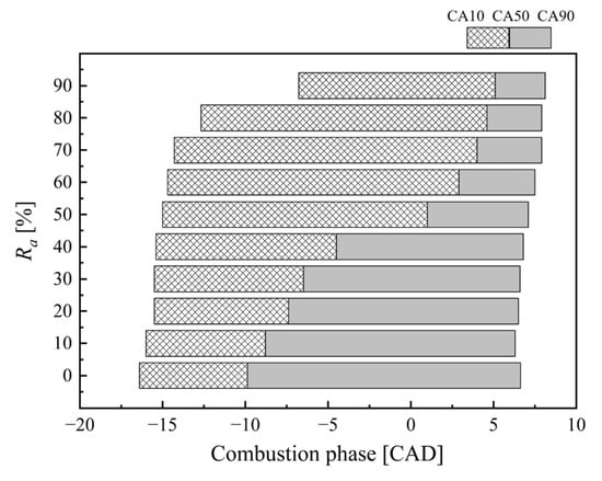
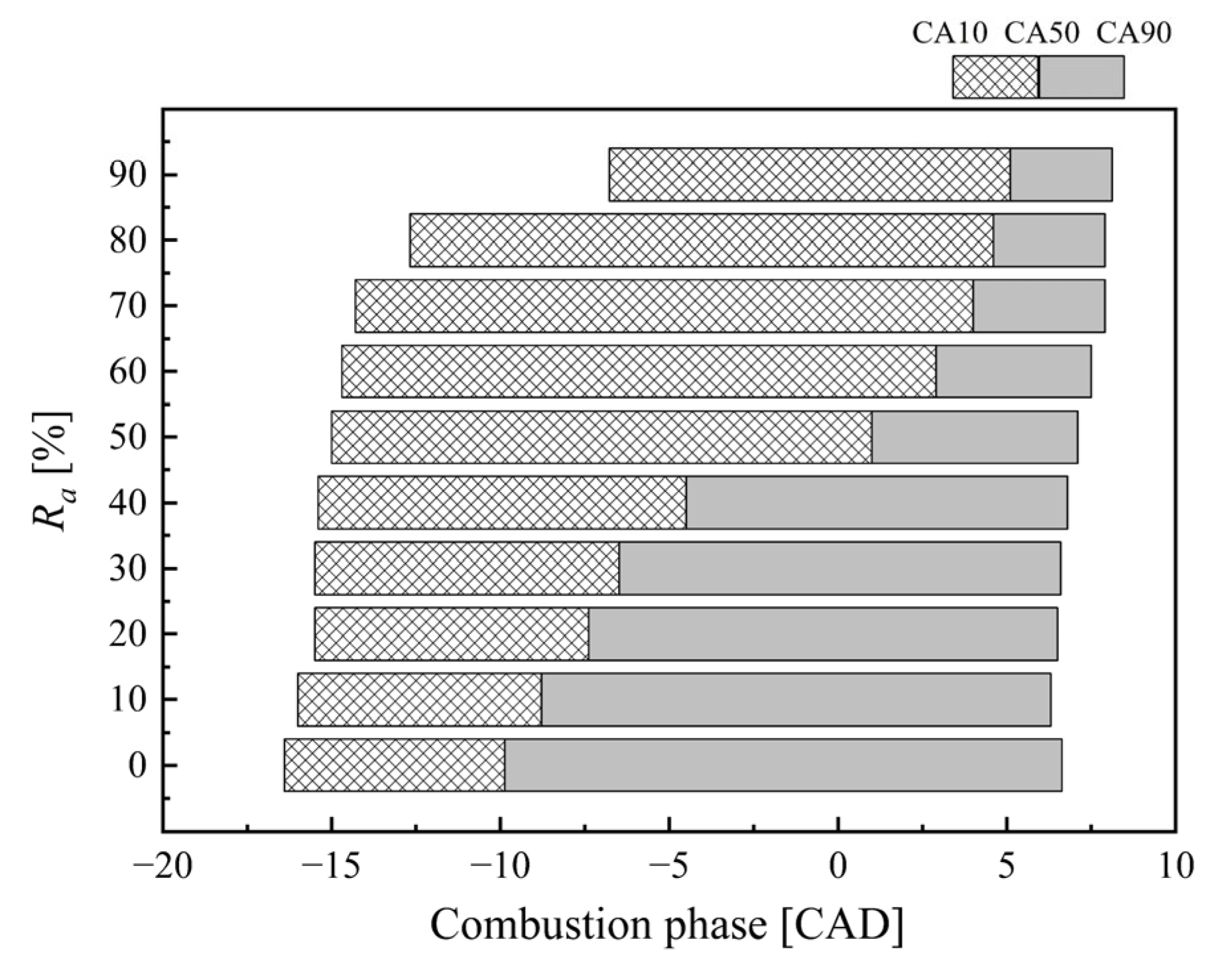
Figure 9 illustrates the evolution of combustion phasing—specifically the start (CA10), midpoint (CA50), and end (CA90) of combustion—across varying ammonia blending ratios (Ra). As Ra increases, the entire combustion process exhibits a distinct shift towards a later phasing. CA10 shifts significantly from −16.5° CA at Ra = 0 (pure diesel) to −6.8° CA at Ra = 90%, a delay of 9.7° CA. This delay is primarily attributed to the shift in energy supply from the early diesel injection to the later ammonia injection. This retardation is even more pronounced for the Center of Heat Release (CA50), which shifts from −9.8° CA (BTDC) at Ra = 0 to 5.1° CA (ATDC) at Ra = 90%, representing a total phase lag of 14.9° CA. Rather than compromising efficiency, this shift repositions the combustion from an overly advanced state to a thermodynamically more optimal phasing. In internal combustion engines, an optimal CA50 always occurs after Top Dead Center (TDC). The excessively early combustion in the baseline N0 case significantly increases heat transfer losses and negative compression work, which completely overcompensate for any theoretical gains from a longer expansion. Therefore, the later ammonia injection physically shifts the energy release to a more favorable position for effective work extraction. These trends confirm that the combustion process is governed by the injection schedule rather than chemical kinetic limitations.
Figure 9.
Effect of blending ratio on combustion phase.
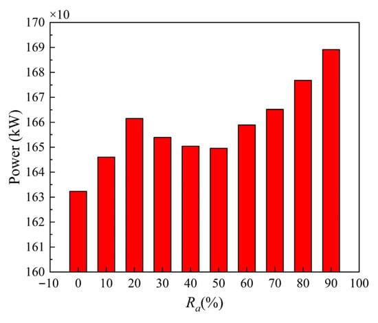
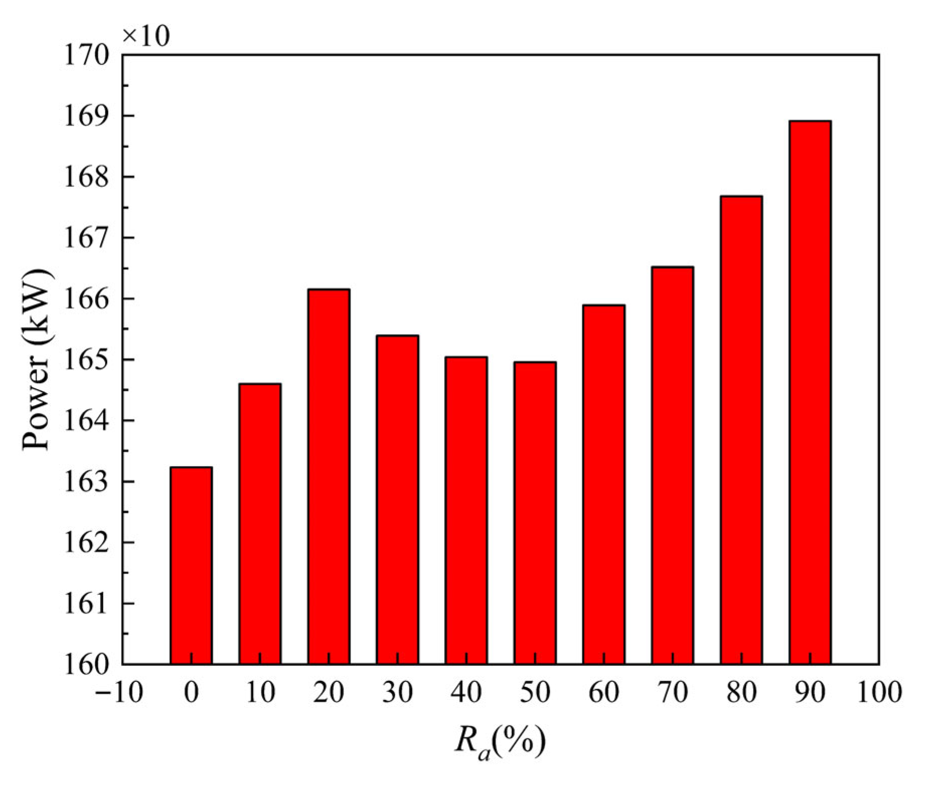
Figure 10 depicts the non-monotonic evolution of indicated power as a function of the ammonia blending ratio. In sharp contrast to the monotonic decline in peak cylinder pressure observed in Figure 8, the indicated power exhibits an overall “fluctuating upward” trend. Specifically, this evolution involves a slight initial increase in the low-blending regime (N0–N20), followed by a distinct dip in the medium-blending regime (N30–N50), where the energy contribution from the early diesel injection decreases, while the late-cycle work potential from the ammonia injection has not yet fully compensated for the loss of peak pressure. Finally, there is a significant recovery in the high-blending regime (N60–N90). At N90, power peaks at 1689 kW, representing an increase of approximately 3.5% over the 1632 kW baseline at N0. This phenomenon, where indicated power increases despite a decrease in peak pressure, is primarily attributed to the repositioned combustion phasing. In the baseline N0 case, the overly early diesel injection (−25 CAD) triggers premature heat release during the compression stroke, generating substantial negative work and excessive heat transfer losses. Conversely, the later ammonia injection strategy in the high-blending cases avoids this overly early combustion, repositioning the CA50 to a thermodynamically optimal phase after Top Dead Center (TDC), which minimizes negative compression work and maximizes effective work extraction. Furthermore, to maintain energy input given ammonia’s lower heating value, the increased injected fuel mass augments the total working fluid mass, compensating for the peak pressure deficit and ultimately yielding a net increase in indicated power.
Figure 10.
Effect of blending ratio on power.
3.2. Effect of Temperature in the Engine Cylinder
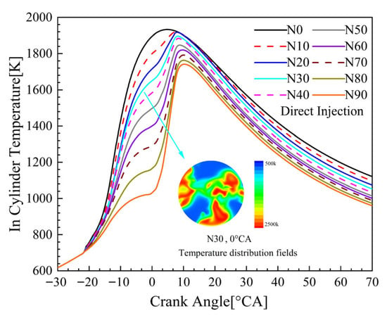
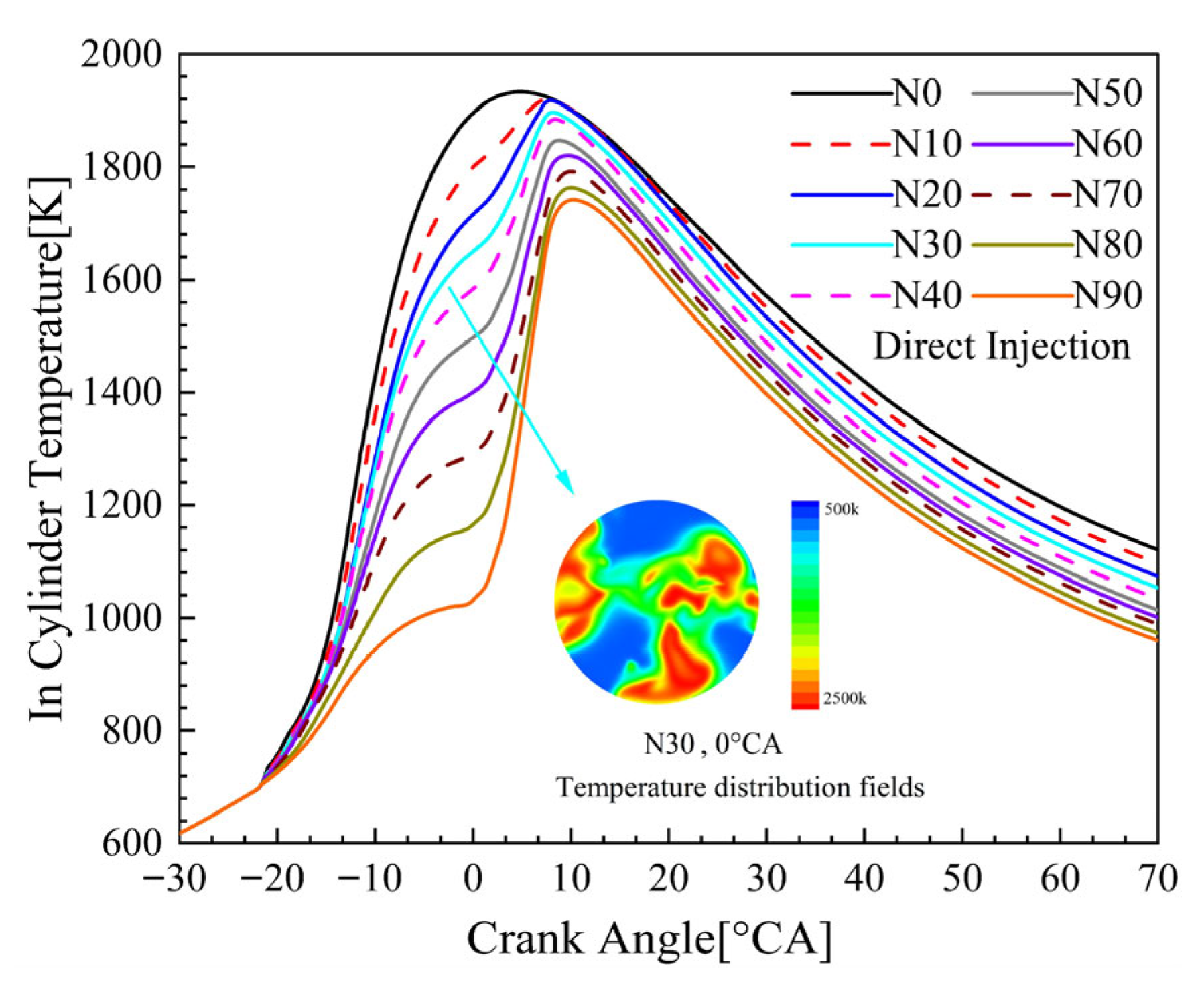
Figure 11 illustrates the evolution of the in-cylinder mean temperature against crank angle across various ammonia blending ratios (N0–N90). As the ammonia ratio increases, the in-cylinder combustion temperature exhibits a monotonic decline. Specifically, the peak temperature decreases from approximately 1940 K in the pure diesel case (N0) to 1740 K in the N90 case, representing a reduction of 200 K. Two primary factors contribute to this phenomenon. First, and most critically, the delayed energy release plays a dominant role. Since the main ammonia injection occurs between −2 and 9 CAD (during the expansion stroke), heat is released into an increasing cylinder volume. This thermodynamic expansion effect naturally prevents the working fluid from reaching the high peak temperatures observed in the early-injection diesel case. Second, ammonia’s high specific heat capacity and latent heat of vaporization absorb substantial heat during the compression and early combustion stages, significantly suppressing the in-cylinder thermal environment. Similar to the pressure profiles, the timing of peak temperature is markedly retarded as Ra increases; the peak shifts from approximately 10° CA ATDC (N0) to beyond 15° CA ATDC (N90). For low-speed two-stroke engines, this shift in the temperature profile aligns with the repositioned combustion. As established, this later combustion actually optimizes thermal efficiency by avoiding the severe heat transfer losses of the premature baseline, although it naturally results in relatively higher exhaust temperatures. Examination of the temperature distribution field for the N30 case at Top Dead Center (TDC, 0° CA) reveals a highly heterogeneous state, characterized by the coexistence of distinct high-temperature zones (red, >2000 K) and low-temperature zones (blue, <1000 K). This heterogeneity is characteristic of diffusion combustion driven by high-pressure injection, where the high-temperature zones follow the spray path, confirming that the process is mixing-controlled rather than limited by global flame propagation.
Figure 11.
Effect of blending Ratio on Cylinder Temperature.
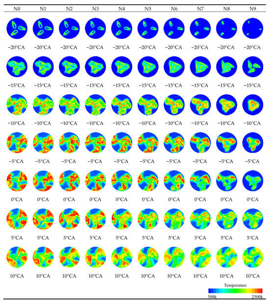
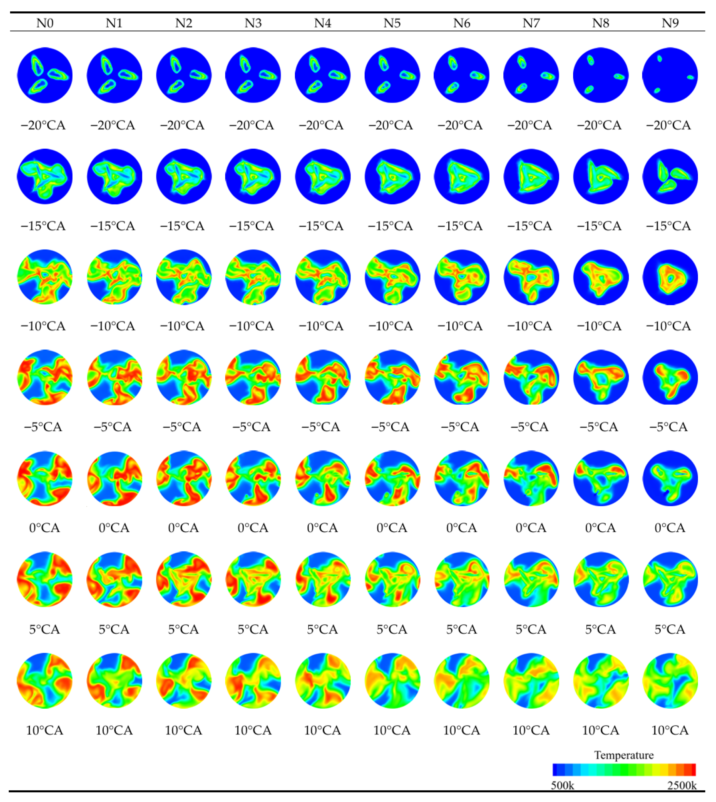
Figure 12 visualizes the spatial evolution of the combustion process. As the ammonia blending ratio increases from N0 to N9, the spatial structure of the combustion field changes significantly, transitioning to a highly localized diffusion combustion mode. At −10° CA, the N0 case already exhibits continuous high-temperature flame kernels. In contrast, the high-blending cases (N7–N9) remain dominated by low-temperature regions. This difference is physically evident because the main ammonia injection (starting at −2 CA) has not yet commenced, whereas the diesel in N0 was injected earlier. During the main combustion phase (0–10° CA), N0 displays a homogeneous combustion structure filling the chamber. Conversely, high-temperature regions in the N9 case are confined to narrow vicinities near the nozzle, manifesting as a diffusion flame structure aligned with the fuel sprays. Notably, extensive low-temperature zones (dark blue) persist at the periphery of the N9 case even during late combustion. This indicates that due to the late injection timing (ending at 9 CA), the flame is spatially confined to the spray mixing zones. As the piston descends, the rapid expansion cools the peripheral regions, potentially causing flame quenching before the late-injected fuel can fully oxidize, which constitutes the direct source of ammonia slip.
Figure 12.
Variation of In-Cylinder Temperature Field.
3.3. Effect of Engine Economy
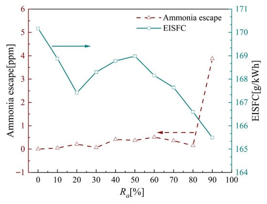
Figure 13 illustrates the trade-off between Equivalent Indicated Specific Fuel Consumption (EISFC) and ammonia slip across varying ammonia blending ratios. Regarding EISFC, the data reveal an overall fluctuating downward trend, indicating enhanced fuel economy at higher ammonia concentrations. In the fluctuation regime (N0–N50), EISFC reaches a local minimum at N20 before rebounding within the N40–N50 interval. This “saddle-shaped” profile correlates strongly with the power fluctuations observed in Figure 11, reflecting the transitional shift in the energy release centroid. As the diesel energy fraction decreases, the combustion phasing shifts, and the fluctuation represents the thermodynamic trade-off between the reducing early work (from diesel) and the increasing late work (from ammonia). Conversely, in the optimization regime (N60–N90), EISFC declines significantly as Ra rises, reaching a minimum of approximately 165.5 g/kWh at N90. This improvement is primarily driven by the optimized combustion phasing. As established earlier, the later ammonia injection physically avoids the premature heat release and severe heat transfer losses of the baseline case, repositioning the combustion to a thermodynamically more favorable phase and thereby elevating the overall cycle thermal efficiency. Regarding ammonia slip, rates remain negligible for most conditions but exhibit a sharp surge at the operational limit. During the stable phase (N0–N80), slip is consistently maintained below 0.5 ppm, suggesting that the ample residence time characteristic of low-speed engines ensures complete ammonia oxidation. However, at N90, the slip rate spikes to approximately 4 ppm. Corroborating the temperature field analysis, this surge is attributed to the late ending of the injection event (at 9 CAD ATDC). Since the final portion of the fuel is introduced during the expansion stroke, the rapid drop in localized temperature leads to flame quenching before the late-injected ammonia can fully oxidize.
Figure 13.
Effect of blending ratio on economy.
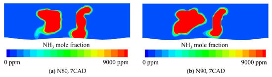
Figure 14 visualizes the spatial distribution of in-cylinder unburned ammonia at 7° CA for the high-blending cases (N80 and N90). The red regions highlight unburned core zones characterized by extremely high ammonia mole fractions (>9000 ppm). Observations regarding local accumulation and combustion quenching reveal that distinct pockets of unburned ammonia persist despite the cycle entering the early expansion phase. These high-concentration pockets accumulate primarily in localized regions distal to the flame center. This provides visual corroboration of the fragmented and discontinuous combustion phenomenon discussed earlier; under high-ammonia conditions like N90, the late injection timing (continuing until 9 CAD) introduces the final portion of the fuel into a rapidly expanding volume. Consequently, the steep drop in localized temperature leads to flame quenching in the spray tails, rather than a failure of flame propagation. These residual ammonia pockets, remaining unignited during early expansion (7° CA), constitute the direct source of ammonia slip. As the piston descends and in-cylinder temperature and pressure decline further, the thermodynamic conditions necessary for re-oxidation are lost. These pockets are ultimately exhausted as unburned ammonia, serving as the physical mechanism responsible for the surge in ammonia slip to 4 ppm observed in Figure 12 for the N90 case.
Figure 14.
Distribution of unburned ammonia at different mixing ratios in the cylinder when crankshaft angle is 7 CA.
3.4. Effects of Engine Emissions
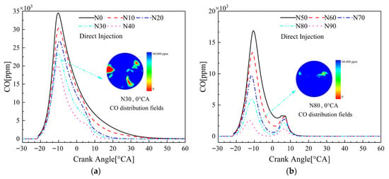
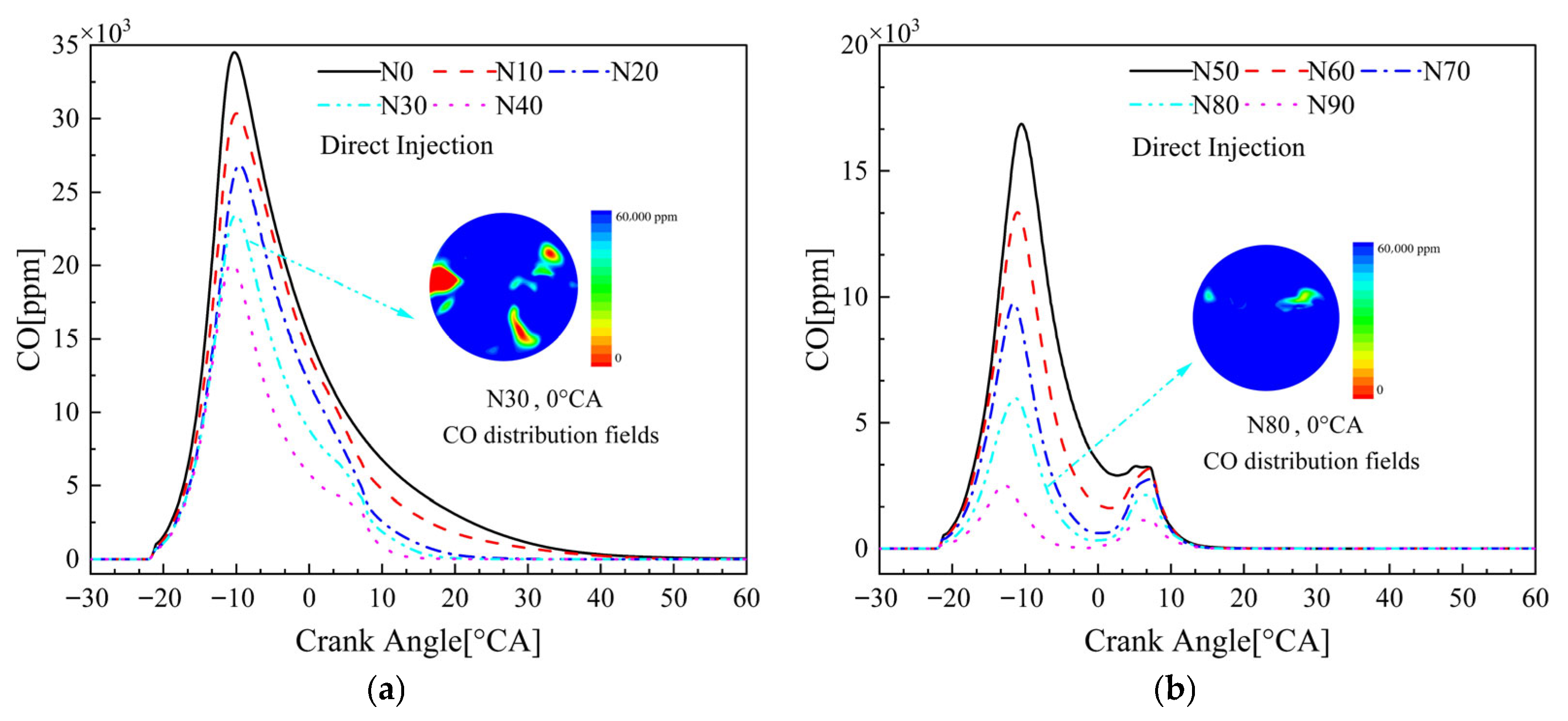
Based on Figure 15, the influence of the ammonia blending ratio on CO emissions exhibits a significant monotonic downward trend, contrary to the conventional expectation that combustion deterioration exacerbates CO production. As the ammonia fraction increases, the peak in-cylinder CO concentration drops precipitously from approximately 35,000 ppm in the pure diesel case (N0) to below 3000 ppm in the high-blending case (N90), a reduction exceeding 90%. This phenomenon is primarily attributed to the dominance of carbon availability reduction. Although the lower in-cylinder temperatures resulting from the delayed energy release (expansion cooling) are theoretically unfavorable for late-stage CO oxidation, ammonia is a carbon-free fuel. Consequently, the reduction in diesel injection, the sole source of carbon atoms, directly eliminates the material basis for CO generation at the source. The embedded concentration field contours further corroborate this mechanism; the high CO concentration zone in the N80 case is confined to a minute region near the spray core, which is significantly smaller than that observed in the N30 case. This confirms that increasing the ammonia substitution ratio is the most direct and effective strategy for mitigating hydrocarbon-based pollutants.
Figure 15.
Effect of ammonia/diesel blending ratio on CO emissions. (a) Effect of low ammonia blending on CO emissions. (b) Effect of high ammonia blending on CO emissions.
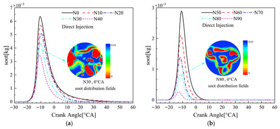
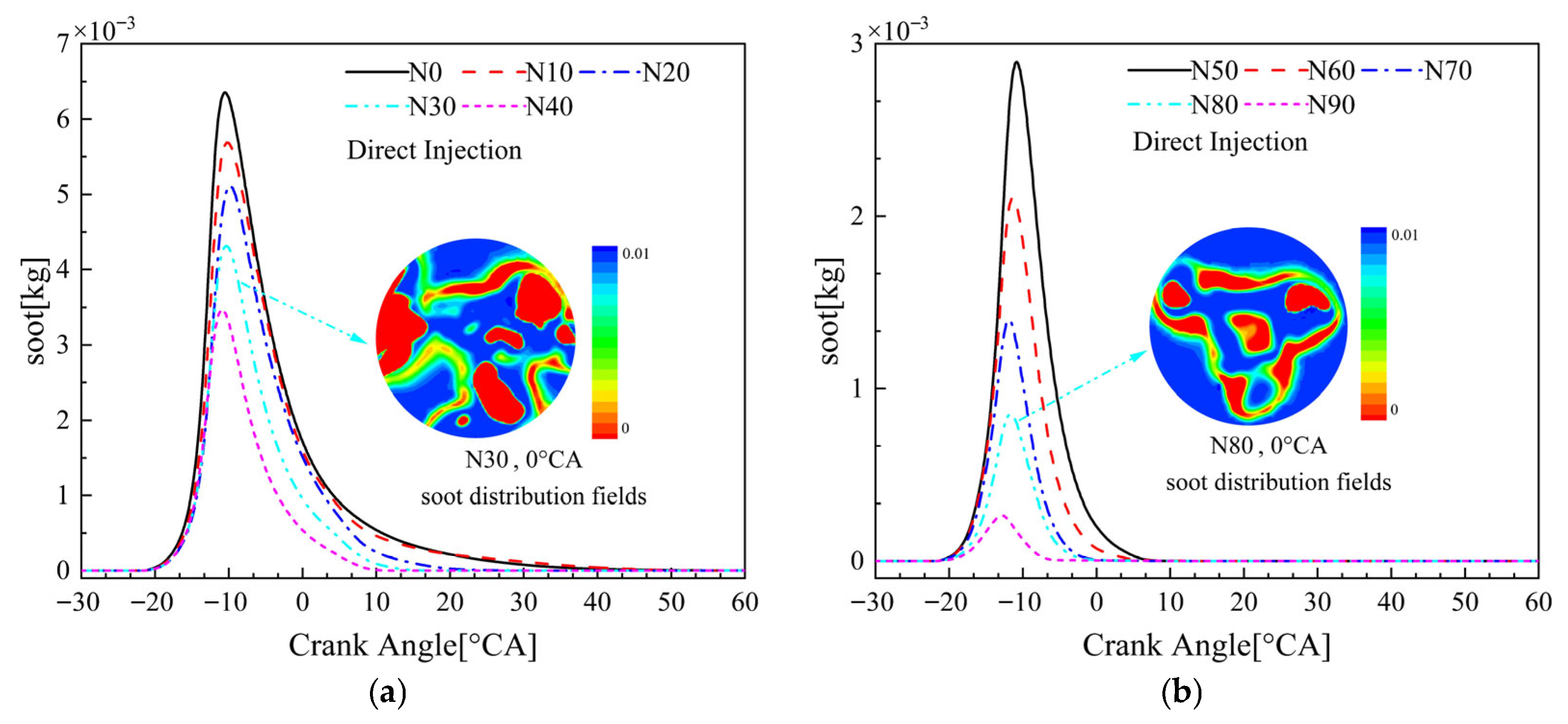
Based on the analysis of Figure 16, the impact of the ammonia blending ratio on soot emissions presents a sharp, monotonic, and precipitous decline. The peak emission mass drops from 6.3 × 10⁻³ kg in the pure diesel case (N0) to near-zero levels in the N90 case, achieving a reduction of over 95%. Unlike CO emissions, which are limited primarily by carbon source availability, soot elimination is attributed more to alterations in the thermodynamic combustion environment and physical constraints on flame topology. As the ammonia ratio increases, the lower peak temperatures resulting from the delayed energy release and expansion cooling effect effectively suppress the thermodynamic conditions required for the high-temperature pyrolysis and nucleation of soot precursors, thereby biasing diesel molecules toward oxidation rather than cracking. Concurrently, the embedded contour plots visually demonstrate that high concentrations of ammonia physically segment and compress the diesel diffusion flame envelope. Consequently, the continuous “envelope-like” soot formation zone observed in the N30 case degenerates into a fragmented and sparse distribution in the N80 case, effectively blocking the spatial pathways for particulate agglomeration and growth.
Figure 16.
Effect of ammonia/diesel blending ratio on soot emission. (a) Effect of low ammonia blending on soot emission. (b) Effect of high ammonia blending on soot emissions.
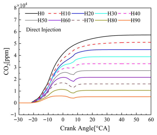
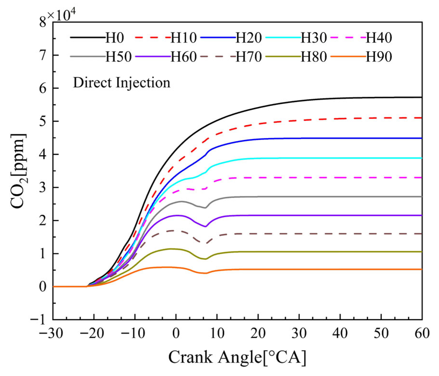
Figure 17 depicts the trajectory of CO2 emissions as a function of the blending ratio, exhibiting a strictly monotonic decline similar to that of CO and soot, yet driven by a more fundamental mechanism. As the blending ratio rises from 0% to 90%, the final CO2 concentration drops precipitously from approximately 5.8 × 10⁻⁴ ppm to 0.5 × 10⁻⁴ ppm, a reduction exceeding 90%. Unlike the formation of CO or soot, which is sensitive to complex combustion states (e.g., temperature and oxidation rates), this substantial decarbonization is governed directly by fuel stoichiometry. As the carbon-free ammonia gradually displaces the carbon-rich diesel, the elemental carbon input is proportionally curtailed at the source. The stabilization of the curve during the late combustion phase (after 20° CA) indicates that despite the delayed combustion phasing inherent to the high-ammonia injection strategy, the diesel fraction ultimately achieves complete oxidation.
Figure 17.
Effect of ammonia/diesel blending ratio on CO2 emissions.
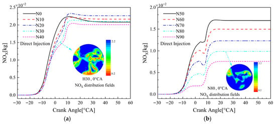
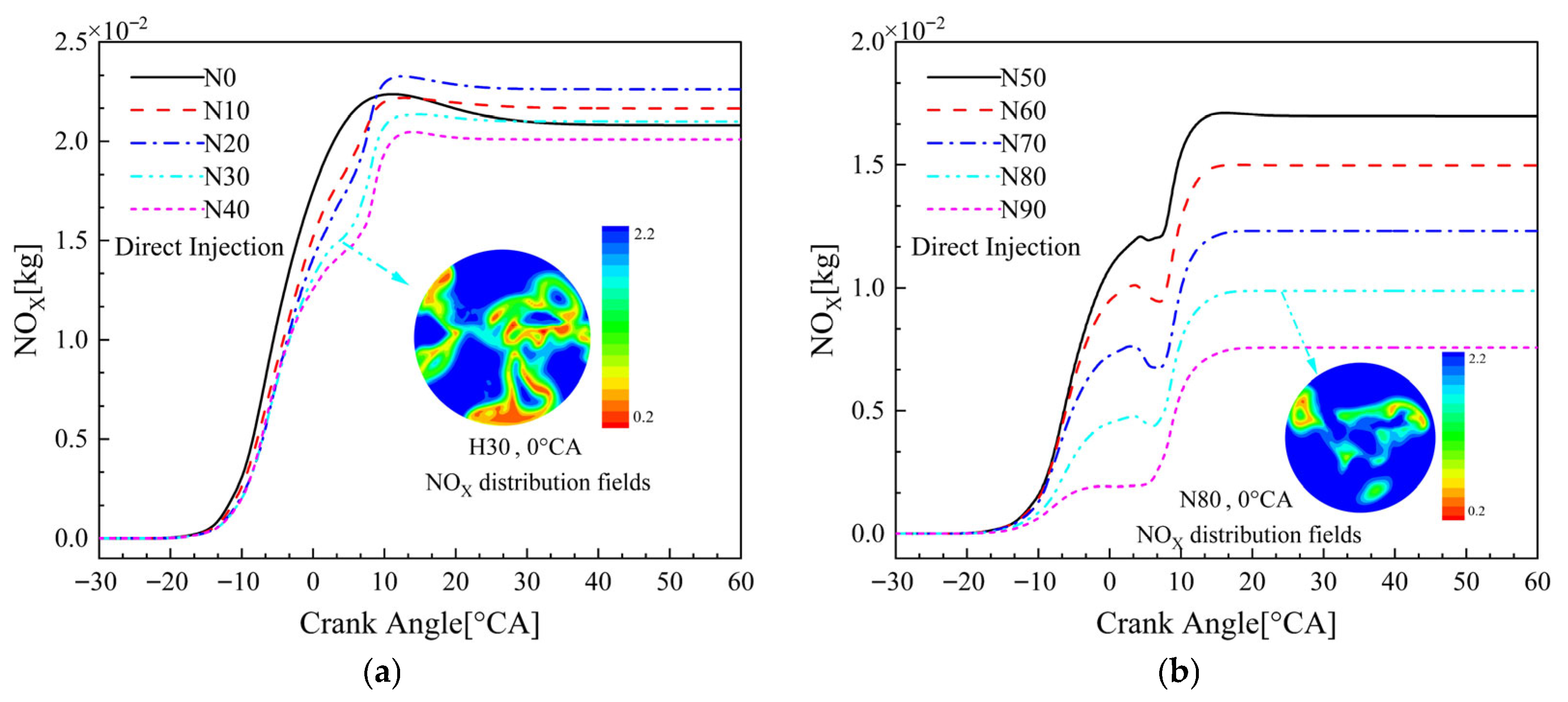
Figure 18 illustrates the evolution of NOx mass accumulation against crank angle across varying ammonia blending ratios. The emissions profile exhibits a non-monotonic trend, characterized by a slight initial increase followed by a substantial decline, resulting from the competitive interaction between “thermal NOx” and “fuel NOx” formation mechanisms. In the low-blending regime (N0–N20), emissions remain elevated, reaching a peak of approximately 2.3 × 10⁻² kg at N20, slightly exceeding the pure diesel baseline. This occurs because the early diesel injection maintains a high-temperature environment conducive to thermal NOx, while the added ammonia acts as a nitrogen carrier, superimposing fuel NOx upon the baseline. Conversely, as Ra increases further (N30–N90), NOx emissions precipitously decline. At N90, the final mass falls to approximately 0.7 × 10⁻² kg, a reduction of nearly 70% relative to the peak. This reversal is primarily driven by the low-temperature combustion environment resulting from the delayed injection strategy. As the main heat release is shifted into the expansion stroke, the peak in-cylinder temperature drops significantly (as shown in Figure 11), thereby disrupting the high-temperature conditions requisite for the Zeldovich mechanism. The embedded concentration contours at 0° CA visually substantiate this shift: while the N30 case exhibits extensive high NOx regions (red/green zones), the N80 case shows NOx confinement to minute, localized areas with significantly reduced concentrations, confirming the potent inhibitory effect of expansion-cooled combustion on NOx synthesis.
Figure 18.
Effect of ammonia/diesel blending ratio on NOx emissions. (a) Effect of low ammonia blending on NOx emissions. (b) Effect of high ammonia blending on NOx emissions.
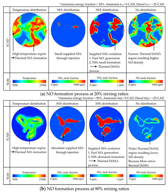
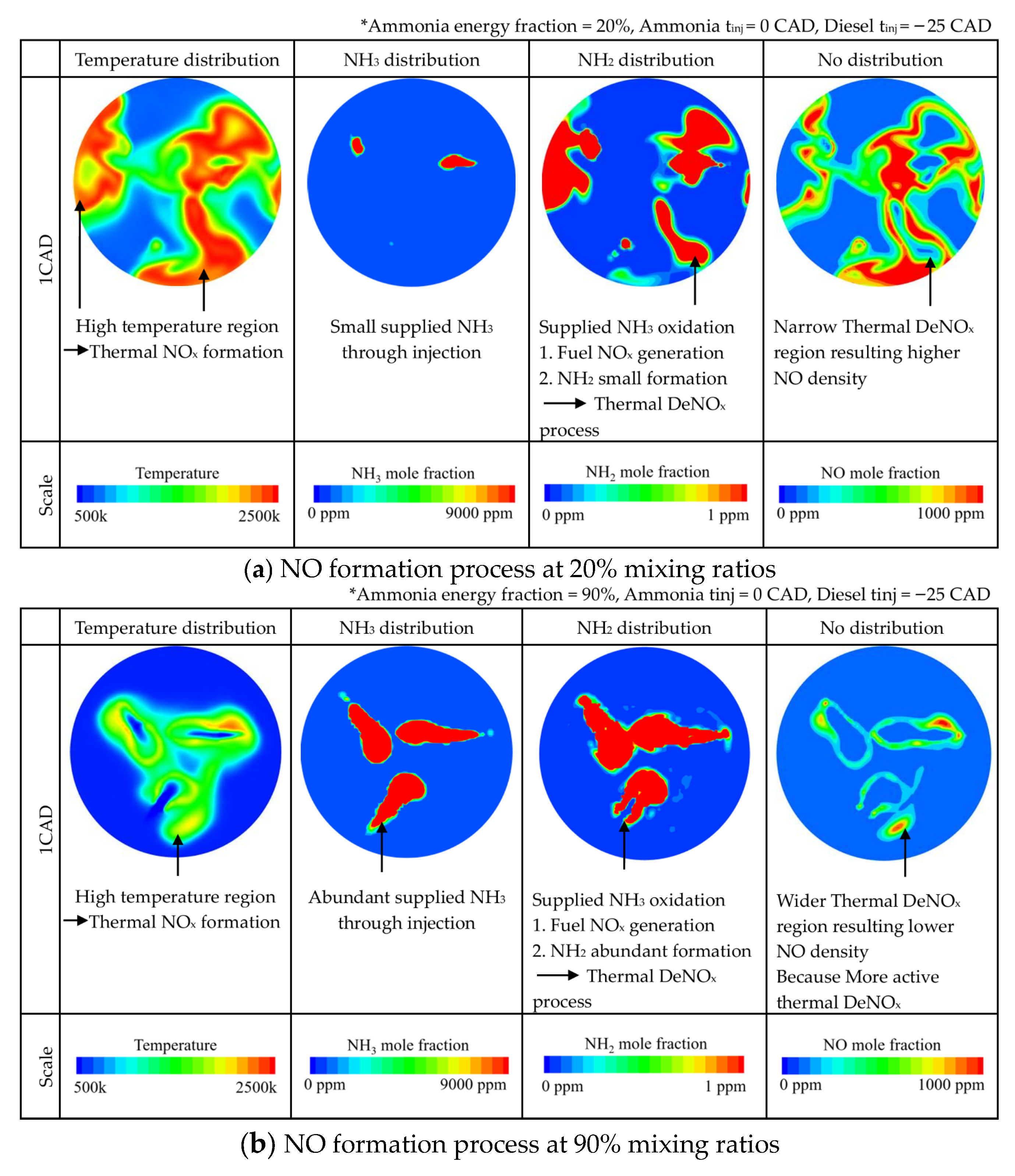
Drawing upon the micro-kinetic analysis in Figure 19, the evolution of NO emissions is governed by the dynamic equilibrium between two competitive mechanisms: “fuel-NO formation” and “Thermal DeNOx.” In the low-blending case (N20), characterized by high-temperature regions maintained by the dominant diesel combustion and low NH2 concentrations, reaction kinetics are dominated by the oxidation pathway (NH2 + O → NO), resulting in substantial NO generation with limited removal. Conversely, the high-blending case (N90) establishes a low temperature and ammonia-rich atmosphere. Here, an abundance of excess NH2 radicals shifts the reaction trajectory toward reduction, efficiently scavenging generated NO via the Thermal DeNOx mechanism (NH2 + NO → N2 + H2O). This intensified self-deNOx effect, synergizing with the physical suppression of thermal NO, effectively scavenges generated NO, providing the fundamental physicochemical explanation for the significant NOx reduction observed at high blending ratios in Figure 18.
Figure 19.
NO formation process in mixing ratios.
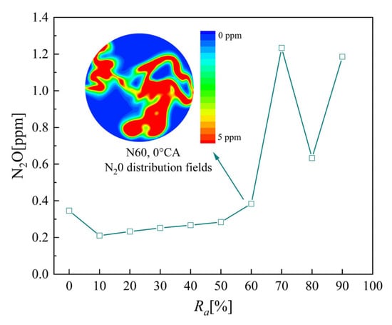
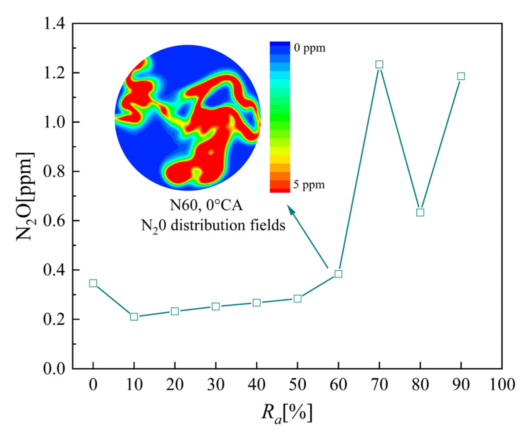
Figure 20 characterizes the non-monotonic response of N2O emissions to the ammonia blending ratio, exhibiting a distinct pattern: a slight dip at low blending, a gradual rise at medium blending, and a volatile surge at high blending. Emissions reach a minimum at N10 before rebounding slowly, eventually culminating in a sharp spike within the N70–N90 high-blending regime. Peak concentrations reach 1.23 ppm and 1.19 ppm, respectively, with levels significantly exceeding the pure diesel baseline. This rapid deterioration stems from a competitive imbalance between formation enhancement and the inhibition of thermal decomposition. On the one hand, elevated ammonia concentrations increase the population of precursor NH2 radicals, potentiating N2O formation via the NH2 + NO → N2O + H pathway. More critically, however, the profoundly reduced in-cylinder temperatures, resulting from the delayed energy release into the expansion stroke, cause the local environment to fall below the critical threshold (>1200 K) required for thermal decomposition of N2O → N2 + O. Consequently, large quantities of generated N2O cannot be consumed and remain “frozen” in the exhaust stream. Despite a transient decline observed at N80, the inhibition of thermal decomposition due to low temperatures prevalent in high-ammonia regimes generally renders the slip of N2O, a potent greenhouse gas, a critical challenge for ammonia-fueled engines.
Figure 20.
Effect of ammonia/diesel blending ratio on N2O emission.
While the results demonstrate a substantial reduction in carbon emissions at high ammonia substitution rates, this benefit presents a significant trade-off with nitrogen-based emissions. The observed increase in NOx and potential N2O formation indicates that ammonia cannot be viewed as a standalone zero-emission solution. Therefore, the ‘deep decarbonization’ potential of the proposed high-pressure injection strategy is contingent upon its integration with efficient aftertreatment systems (SCR and AOC) to mitigate these secondary pollutants.
4. Conclusions
This study employs three-dimensional CFD numerical simulations coupled with chemical reaction kinetics to systematically investigate the impact of varying ammonia energy blending ratios (Ra = 0–90%) on the combustion process, thermodynamic state, and pollutant formation evolution in a marine low-speed two-stroke diesel-ignited ammonia dual-fuel engine. Based on a comprehensive analysis of cylinder pressure profiles, heat release characteristics, microscopic in-cylinder field distributions, and chemical reaction pathways of key emissions, the primary conclusions are summarized as follows:
- The engine maintains robust performance and optimized efficiency under high ammonia blending ratios. Rather than suffering from combustion phase retardation, the late ammonia injection strategy physically avoids the premature heat release, severe negative compression work, and excessive heat transfer losses observed in the early-injection diesel baseline. By repositioning the CA50 to a thermodynamically more optimal phase after Top Dead Center (TDC), the effective work extraction is maximized. Although ammonia has a low laminar flame speed, the high-pressure injection drives a mixing-controlled combustion mode, ensuring rapid energy conversion. Consequently, at the Ra = 90% condition, the indicated power increases to 1689 kW, a 3.5% rise over the pure diesel baseline of 1632 kW, while the Equivalent Indicated Specific Fuel Consumption (EISFC) reaches a minimum of 165.5 g/kWh.
- The introduction of carbon-free ammonia fundamentally eliminates the source of carbon-based pollutants. As Ra increases from 0% to 90%, CO2 concentrations drop precipitously from 5.8 ×10⁴ ppm to 0.5 × 10⁴ ppm, while peak CO emissions are reduced by over 90%. Moreover, soot emissions exhibit a decline of over 95%. This near-zero particulate emission is achieved not only by carbon source reduction but also by the delayed injection strategy, which lowers peak temperatures and physically fragments the soot formation envelope, preventing agglomeration.
- NOx emissions exhibit a non-monotonic trend, with a significant reduction at high blending ratios (approx. 70% reduction at N90). Mechanism analysis reveals that this reduction is primarily governed by the low-temperature environment resulting from expansion cooling (due to the delayed heat release), which physically suppresses the thermal Zeldovich mechanism. Synergistically, the abundance of in-cylinder NH2 radicals establishes a strong reducing atmosphere, facilitating Thermal DeNOx reactions (NH2 + NO → N2) that effectively scavenge generated NO.
- The late ending of the ammonia injection event creates challenges for complete oxidation. The rapid expansion during the tail end of injection causes localized flame quenching, leading to an ammonia slip of 4 ppm at N90. Furthermore, the significantly reduced in-cylinder temperatures compromise the thermodynamic conditions required for the thermal decomposition of N2O, causing emissions of this potent greenhouse gas to peak at 1.23 ppm in the N70 case. These findings underscore that injection timing optimization is critical to mitigating the trade-off between thermal efficiency and the slip of N2O and unburned ammonia.
Although the high-pressure direct injection strategy significantly mitigates ammonia slip and N2O generation at the source, complying with strict zero-emission regulations requires a holistic approach. Therefore, integrating exhaust-after-treatment systems, specifically Ammonia Oxidation Catalysts (AOC) for slip elimination, Selective Catalytic Reduction (SCR) for NOx (NO and NO2) reduction, and dedicated catalysts for N2O decomposition, remains essential. The in-cylinder optimization presented in this study serves to minimize the pollutant mass flow entering these systems, thereby effectively reducing their required catalyst volume and operational costs.
Author Contributions
Y.-P.L.: Writing—original draft, Investigation. E.-Z.S.: Writing—review & editing, Supervision, Methodology, Funding acquisition, Conceptualization, Formal analysis. K.-S.S.: Resources. Y.-L.N.: Writing—review & editing. All authors have read and agreed to the published version of the manuscript.
Funding
This work was supported by the Shandong Provincial Key Research and Development Program [grant number 2023CXGC010404], Shandong (Yantai) Sino-Japan Industrial Technology Research Institute Open Topics [grant number KXDNY2024-9].
Data Availability Statement
Data will be made available upon request.
Conflicts of Interest
The authors declare no conflicts of interest.
Nomenclature
| Ra | Ammonia energy blending ratio |
| EISFC | Equivalent Indicated Specific Fuel Consumption |
| HRR | Heat Release Rate |
| Pmax | Peak In-Cylinder Pressure |
| CA10/CA50/CA90 | Crank angle at 10%, 50%, and 90% cumulative heat release |
| SODI/EODI | Start/End of Diesel Injection |
| ATDC/BTDC | After/Before Top Dead Center |
| IVC/EVO | Intake Valve Closing/Exhaust Valve Opening |
| TDC | Top Dead Center |
| CFD | Computational Fluid Dynamics |
| MN/MD | Mass of ammonia/diesel |
| HN/HD | Lower heating value of ammonia/diesel |
References
- Battin, T.J.; Luyssaert, S.; Kaplan, L.A.; Aufdenkampe, A.K.; Richter, A.; Tranvik, L.J. The boundless carbon cycle. Nat. Geosci. 2009, 2, 598–600. [Google Scholar] [CrossRef] [Scilit]
- Wang, Y.; Cao, Q.; Liu, L.; Wu, Y.; Liu, H.; Gu, Z.; Zhu, C. A review of low and zero carbon fuel technologies: Achieving ship carbon reduction targets. Sustain. Energy Technol. Assess. 2022, 54, 102762. [Google Scholar] [CrossRef] [Scilit]
- Farkas, A.; Degiuli, N.; Martić, I.; Vujanović, M. Greenhouse gas emissions reduction potential by using antifouling coatings in a maritime transport industry. J. Clean. Prod. 2021, 295, 126428. [Google Scholar] [CrossRef] [Scilit]
- Tock, L.; Marechal, F.; Perrenoud, M. Thermo-environomic evaluation of the ammonia production. Can. J. Chem. Eng. 2015, 93, 356–362. [Google Scholar] [CrossRef] [Scilit]
- Joung, T.-H.; Kang, S.-G.; Lee, J.-K.; Ahn, J. The IMO initial strategy for reducing Greenhouse Gas(GHG) emissions, and its follow-up actions towards 2050. J. Int. Marit. Saf. Environ. Aff. Shipp. 2020, 4, 1–7. [Google Scholar] [CrossRef] [Scilit]
- Zhang, Z.; Long, W.; Dong, P.; Tian, H.; Tian, J.; Li, B.; Wang, Y. Performance characteristics of a two-stroke low speed engine applying ammonia/diesel dual direct injection strategy. Fuel 2023, 332, 126086. [Google Scholar] [CrossRef] [Scilit]
- Liu, L.; Wu, Y.; Wang, Y. Numerical investigation on the combustion and emission characteristics of ammonia in a low-speed two-stroke marine engine. Fuel 2022, 314, 122727. [Google Scholar] [CrossRef] [Scilit]
- Juangsa, F.B.; Irhamna, A.R.; Aziz, M. Production of ammonia as potential hydrogen carrier: Review on thermochemical and electrochemical processes. Int. J. Hydrogen Energy 2021, 46, 14455–14477. [Google Scholar] [CrossRef] [Scilit]
- Dimitriou, P.; Javaid, R. A review of ammonia as a compression ignition engine fuel. Int. J. Hydrogen Energy 2020, 45, 7098–7118. [Google Scholar] [CrossRef] [Scilit]
- Lee, D.; Song, H.H. Development of combustion strategy for the internal combustion engine fueled by ammonia and its operating characteristics. J. Mech. Sci. Technol. 2018, 32, 1905–1925. [Google Scholar] [CrossRef] [Scilit]
- Kurien, C.; Mittal, M. Review on the production and utilization of green ammonia as an alternate fuel in dual-fuel compression ignition engines. Energy Convers. Manag. 2022, 251, 114990. [Google Scholar] [CrossRef] [Scilit]
- Gray, J.T., Jr.; Dimitroff, E.; Meckel, N.T.; Quillian, R.D., Jr. Ammonia Fuel—Engine Compatibility and Combustion; SAE Transactions: Warrendale, PA, USA, 1967; pp. 785–807. [Google Scholar]
- Reiter, A.J.; Kong, S.-C. Diesel engine operation using ammonia as a carbon-free fuel. In Proceedings of the ASME 2010 Internal Combustion Engine Division Fall Technical Conference, San Antonio, TX, USA, 12–15 September 2010; pp. 111–117. [Google Scholar]
- Reiter, A.J.; Kong, S.-C. Demonstration of compression-ignition engine combustion using ammonia in reducing greenhouse gas emissions. Energy Fuels 2008, 22, 2963–2971. [Google Scholar] [CrossRef] [Scilit]
- Reiter, A.J.; Kong, S.-C. Combustion and emissions characteristics of compression-ignition engine using dual ammonia-diesel fuel. Fuel 2011, 90, 87–97. [Google Scholar] [CrossRef] [Scilit]
- Førby, N.; Thomsen, T.B.; Cordtz, R.F.; Bræstrup, F.; Schramm, J. Ignition and combustion study of premixed ammonia using GDI pilot injection in CI engine. Fuel 2023, 331, 125768. [Google Scholar] [CrossRef] [Scilit]
- Pham, Q.; Park, S.; Agarwal, A.K.; Park, S. Review of dual-fuel combustion in the compression-ignition engine: Spray, combustion, and emission. Energy 2022, 250, 123778. [Google Scholar] [CrossRef] [Scilit]
- Awad, O.I.; Zhou, B.; Harrath, K.; Kadirgama, K. Characteristics of NH3/H2 blend as carbon-free fuels: A review. Int. J. Hydrogen Energy 2023, 48, 38077–38100. [Google Scholar] [CrossRef] [Scilit]
- Zhou, X.; Li, T.; Wang, N.; Wang, X.; Chen, R.; Li, S. Pilot diesel-ignited ammonia dual fuel low-speed marine engines: A comparative analysis of ammonia premixed and high-pressure spray combustion modes with CFD simulation. Renew. Sustain. Energy Rev. 2023, 173, 113108. [Google Scholar] [CrossRef] [Scilit]
- Niki, Y.; Yoo, D.-H.; Hirata, K.; Sekiguchi, H. Effects of ammonia gas mixed into intake air on combustion and emissions characteristics in diesel engine. In Internal Combustion Engine Division Fall Technical Conference; American Society of Mechanical Engineers: New York, NY, USA, 2016; p. V001T003A004. [Google Scholar]
- Niki, Y.; Nitta, Y.; Sekiguchi, H.; Hirata, K. Diesel fuel multiple injection effects on emission characteristics of diesel engine mixed ammonia gas into intake air. J. Eng. Gas Turbines Power 2019, 141, 061020. [Google Scholar] [CrossRef] [Scilit]
- Shin, J.; Park, S. Numerical analysis and optimization of combustion and emissions in an ammonia-diesel dual-fuel engine using an ammonia direct injection strategy. Energy 2024, 289, 130014. [Google Scholar] [CrossRef] [Scilit]
- Han, Z.; Reitz, R.D. Turbulence Modeling of Internal Combustion Engines Using RNG κ-ε Models. Combust. Sci. Technol. 1995, 106, 267–295. [Google Scholar] [CrossRef] [Scilit]
- Ricart, L.M.; Reltz, R.D.; Dec, J.E. Comparisons of Diesel Spray Liquid Penetration and Vapor Fuel Distributions with In-Cylinder Optical Measurements. J. Eng. Gas Turbines Power 2000, 122, 588–595. [Google Scholar] [CrossRef] [Scilit]
- O’Rourke, P.J.; Amsden, A.A. A Spray/Wall Interaction Submodel for the KIVA-3 Wall Film Model; SAE Technical Paper 2000-01-0271; SAE International: Warrendale, PA, USA, 2000. [Google Scholar] [CrossRef] [Scilit]
- Schmidt, D.P.; Rutland, C.J. A new droplet collision algorithm. J. Comput. Phys. 2000, 164, 62–80. [Google Scholar] [CrossRef] [Scilit]
- Senecal, P.; Pomraning, E.; Richards, K.; Briggs, T.E.; Choi, C.Y.; Mcdavid, R.; Patterson, M.A. Multi-Dimensional Modeling of Direct-Injection Diesel Spray Liquid Length and Flame Lift-off Length using CFD and Parallel Detailed Chemistry; SAE Technical Paper 2003-01-1043; SAE International: Warrendale, PA, USA, 2003. [Google Scholar] [CrossRef] [Scilit]
- Sun, K.; Liu, H.; Song, E.; Zang, L.; Ning, Y. Development of a reduced multi-component combustion mechanism for a ammonia /diesel dual fuel engine by cross-reaction analysis. Energy 2025, 334, 137785. [Google Scholar] [CrossRef] [Scilit]
- Zeldovitch, J. The oxidation of nitrogen in combustion and explosions. In Selected Works of Yakov Borisovich Zeldovich, Volume I; Princeton University Press: Princeton, NJ, USA, 1946. [Google Scholar] [CrossRef] [Scilit]
- Hiroyasu, H.; Kadota, T. Models for Combustion and Formation of Nitric Oxide and Soot in Direct Injection Diesel Engines. In Proceedings of the 1976 Automotive Engineering Congress and Exposition, Detroit, MI, USA, 23–27 February 1976; pp. 327–335. [Google Scholar]
- Sun, K.; Song, E.-Z.; Lu, H.; Ning, Y.-L. Simulation study on diesel-ignited ammonia/hydrogen mixture fuel combustion on engine combustion and emission performance. J. Mar. Eng. Technol. 2025, 24, 432–443. [Google Scholar] [CrossRef] [Scilit]

Disclaimer/Publisher’s Note: The statements, opinions and data contained in all publications are solely those of the individual author(s) and contributor(s) and not of MDPI and/or the editor(s). MDPI and/or the editor(s) disclaim responsibility for any injury to people or property resulting from any ideas, methods, instructions or products referred to in the content. |
© 2026 by the authors. Licensee MDPI, Basel, Switzerland. This article is an open access article distributed under the terms and conditions of the Creative Commons Attribution (CC BY) license.