


Abstract
Floating offshore wind turbines (FOWTs) are essential for exploiting wind energy in deep and remote seas, overcoming the water-depth limitations of fixed-bottom turbines. However, their operation and maintenance (O&M) complexity and cost increase accordingly, prompting a shift from traditional methods to on-site operations. The replacement of large components—such as blades, generators, and nacelles—is one of the most critical and high-risk operations. To address these challenges, this study investigates the dynamic coupling characteristics between a floating wind turbine and a semi-submersible crane vessel during offshore large-component replacement. Focusing on the blade lowering phase, the effects of sling stiffness and lowering speed on the dynamic response of the blade lowering process are examined. The simulations consider a single environment with a significant wave height of 1.5 m, a spectral peak period of 6 s, and a 10 m reference wind speed of 12 m/s. In the first 200 s of lowering, the Sling 3 case exhibits a peak blade roll of approximately 3.5° and a peak plotted sling tension of about 180 kN, compared with about 110 kN for Sling 1 and Sling 2. The results provide important engineering guidance for improving the stability and safety of on-site large-component replacement operations and reducing maintenance costs.
1. Introduction
With the continuous rise in global energy consumption, the large-scale utilization of traditional fossil fuels has given rise to prominent environmental issues. Against this backdrop, offshore wind power, endowed with unique advantages—including land resource conservation, outstanding power generation efficiency, and ecological friendliness—has gradually become a key development direction in the energy strategies of various countries [1,2].
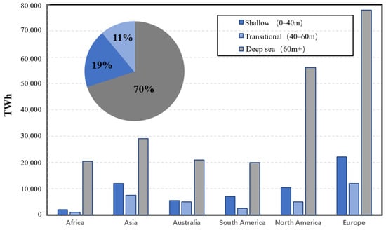
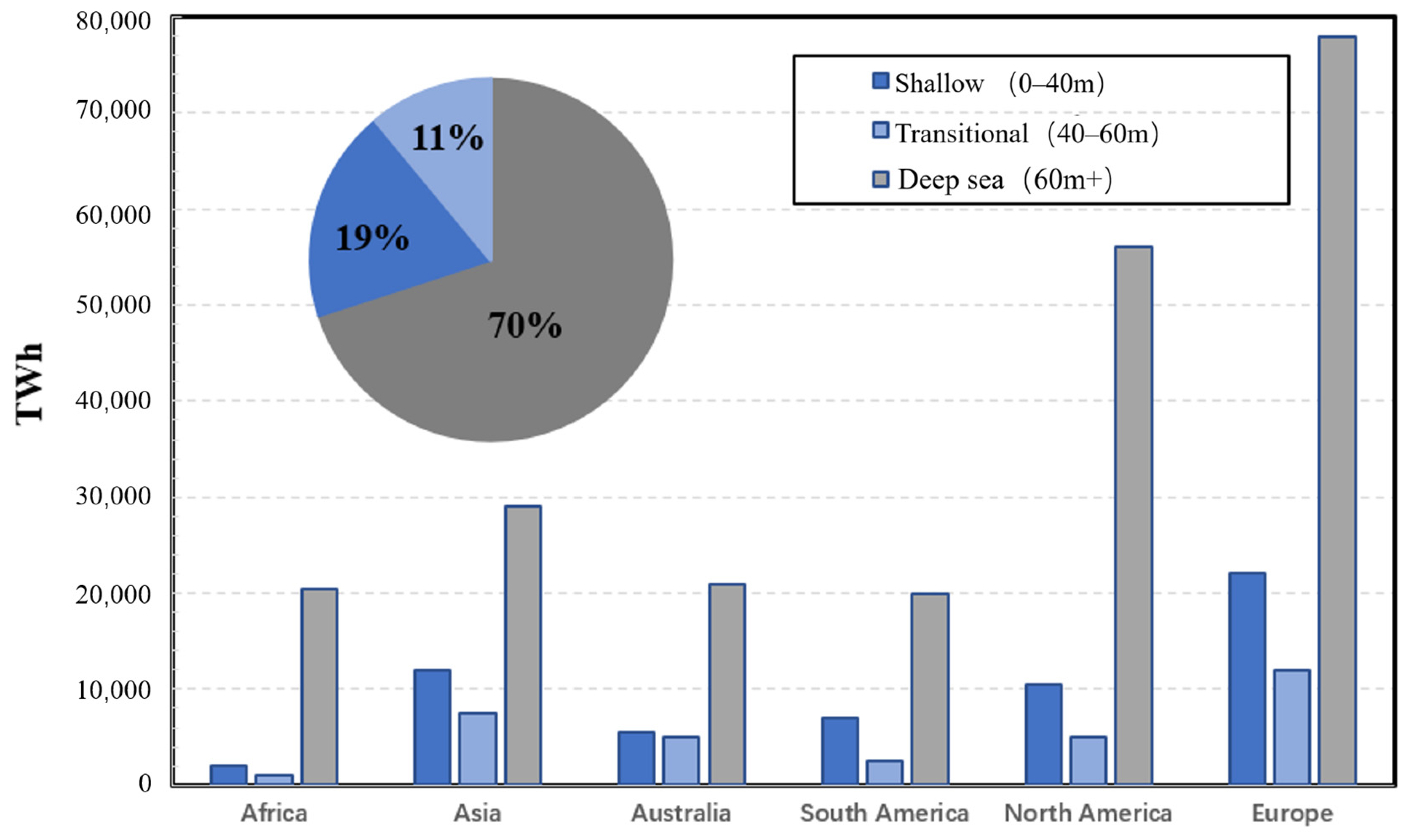
Compared with onshore wind turbines, offshore wind turbines are closer to load centers and exert less impact on humans and the ecological environment [3,4,5]. However, the development of nearshore offshore wind power is constrained by issues such as limited resources, stringent ecological restrictions, and scattered wind farm sites. When the water depth exceeds 60 m, the economic viability of nearshore fixed-bottom offshore wind power declines significantly [6,7]. Currently, wind farms on land, in intertidal zones, and nearshore areas worldwide are nearly saturated. Furthermore, 70–80% of global wind energy resources are distributed in sea areas with water depths exceeding 40 m, as illustrated in Figure 1. Therefore, the development of wind farms in deep and far-reaching seas has become an inevitable trend [8,9], and floating offshore wind turbine (FOWT) technology has emerged as one of the research hotspots.
Figure 1.
Annual energy production (AEP) potential of offshore wind farms at different marine water depths across various countries and regions.
At present, the lifespan of offshore wind farms is continuously being extended [5,10]. The life cycle of offshore wind turbines consists of several phases, among which the installation and operation and maintenance (O&M) costs account for approximately 50% of the total investment [11]. With the advancement of offshore wind power development into deep and far-reaching sea areas, the application of floating offshore wind turbine (FOWT) technology has become increasingly widespread. This brings numerous benefits while indicating a harsher environment for installation and O&M.
As water depth and offshore distance increase, the O&M operations of FOWTs become more complex [12], rendering traditional main component replacement vessels [13] and Tow-to-Shore (T2S) technology [14] hardly applicable. With the gradual expansion of FOWT O&M sites into deep and far-reaching seas, the industry has proposed various solutions to address the challenge of efficient offshore maintenance. These include on-site O&M operations using large floating crane vessels or towing FOWTs to shallow-water areas suitable for heavy-lift crane vessels and jack-up crane vessels [15]. In 2024, the Kincardine offshore wind farm in Scotland successfully completed the world’s first on-site generator replacement for a floating offshore wind turbine.
During the on-site O&M operations of FOWTs, the dynamic response of the crane vessel directly affects the stability of lifting operations [16]. In offshore lifting operations, crane vessels often rely on mooring systems for positioning to ensure operational stability [17,18]. In the research on mooring positioning systems, mooring line modeling methods can be divided into static analysis and dynamic analysis. Deng et al. [19] focused on the mooring system of semi-submersible floating wind turbines and, based on the classical catenary line theory, proposed a design method for the mooring system using the quasi-static analysis method. Yu et al. [20] constructed a multi-buoy mooring system model using the catenary method (a static analysis approach) and analyzed parameters such as mooring line tension. However, the static mooring model cannot accurately calculate the tension of the mooring line. Therefore, Du et al. [21] adopted a dynamic mooring model coupled with CFD to develop a high-precision calculation method, providing an efficient and accurate numerical simulation approach for the design of floating wind turbines and other floating structures.
Meanwhile, under the complex environmental conditions of deep and far-reaching seas, the coupled system composed of the crane vessel, FOWT, and lifting system exhibits significant nonlinear dynamic characteristics [22]. Clarifying the coupled dynamic response characteristics among the crane vessel, FOWT, and lifting system is crucial. Yang et al. [6] utilized computational fluid dynamics (CFD) and hydrodynamic correction methods (fluid mechanics correction methods) to study the load response of a 10 MW FOWT installed on a semi-submersible platform, and they evaluated various correction methods to enhance the fluid dynamics modeling accuracy of the FOWT. Yang et al. [23] also conducted a comparative analysis using high-fidelity simulation tools and CFD to evaluate the performance of the fully coupled floating offshore wind turbine (FOWT) system under three different design load conditions, especially in extreme weather scenarios. Ha et al. [24] employed a combination of model tests and numerical simulations to thoroughly investigate the dynamic behavior of floating crane vessels during the installation and docking of wind turbine upper components. Zhao et al. [25] selected three different vessel types and compared their motion response differences during the single-blade lifting of wind turbines.
To address the deficiencies in existing research on offshore on-site operation and maintenance of wind turbines, this study focuses on the large-component replacement of wind turbines and investigates the coupled dynamic response characteristics between the crane vessel and the wind turbine during blade lowering operations. Firstly, the hydrodynamic characteristics of a semi-submersible crane vessel (SSCV) and a semi-submersible wind turbine are analyzed using the hydrodynamic analysis software AQWA 2023 R1. Subsequently, dynamic time-domain simulations of the blade lowering process during large-component disassembly and replacement are carried out based on an eight-point mooring scheme to explore the dynamic response characteristics between the crane vessel and the blade, as well as the influences of sling parameters and lowering speed on the lifting system. This study provides important engineering guidance for the operational strategies of on-site large-component replacement of floating wind turbines. Section 2 introduces the theoretical foundations adopted in this study. Section 3 describes the crane vessel model, the floating wind turbine model, and the corresponding mooring line parameters. Section 4 presents the hydrodynamic results of the crane vessel and the floating wind turbine. Section 5 investigates the effects of sling stiffness and lowering speed on the dynamic response of the blade. Section 6 summarizes the full text and draws relevant conclusions.
2. Theoretical Background
2.1. Coordinate System Definition
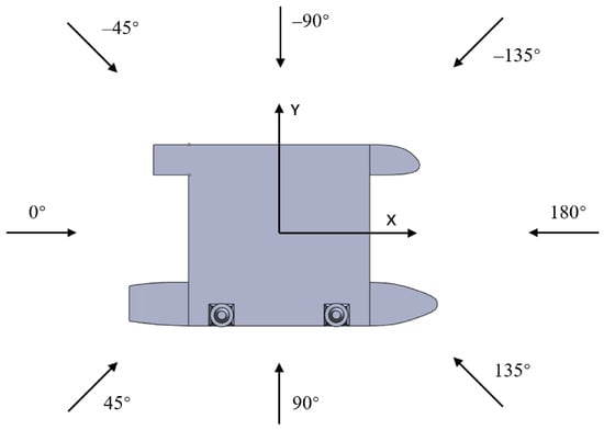
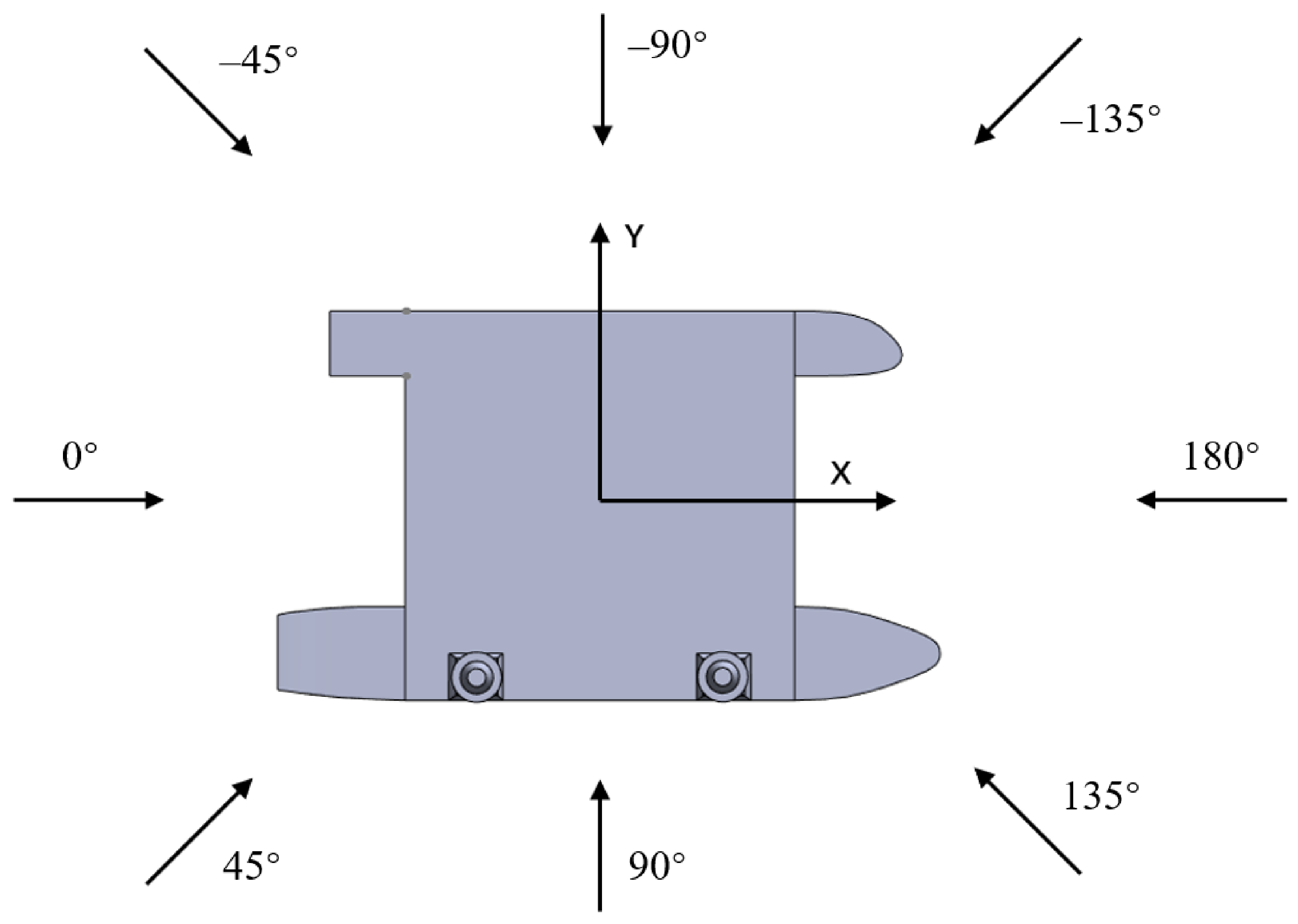
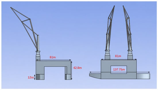
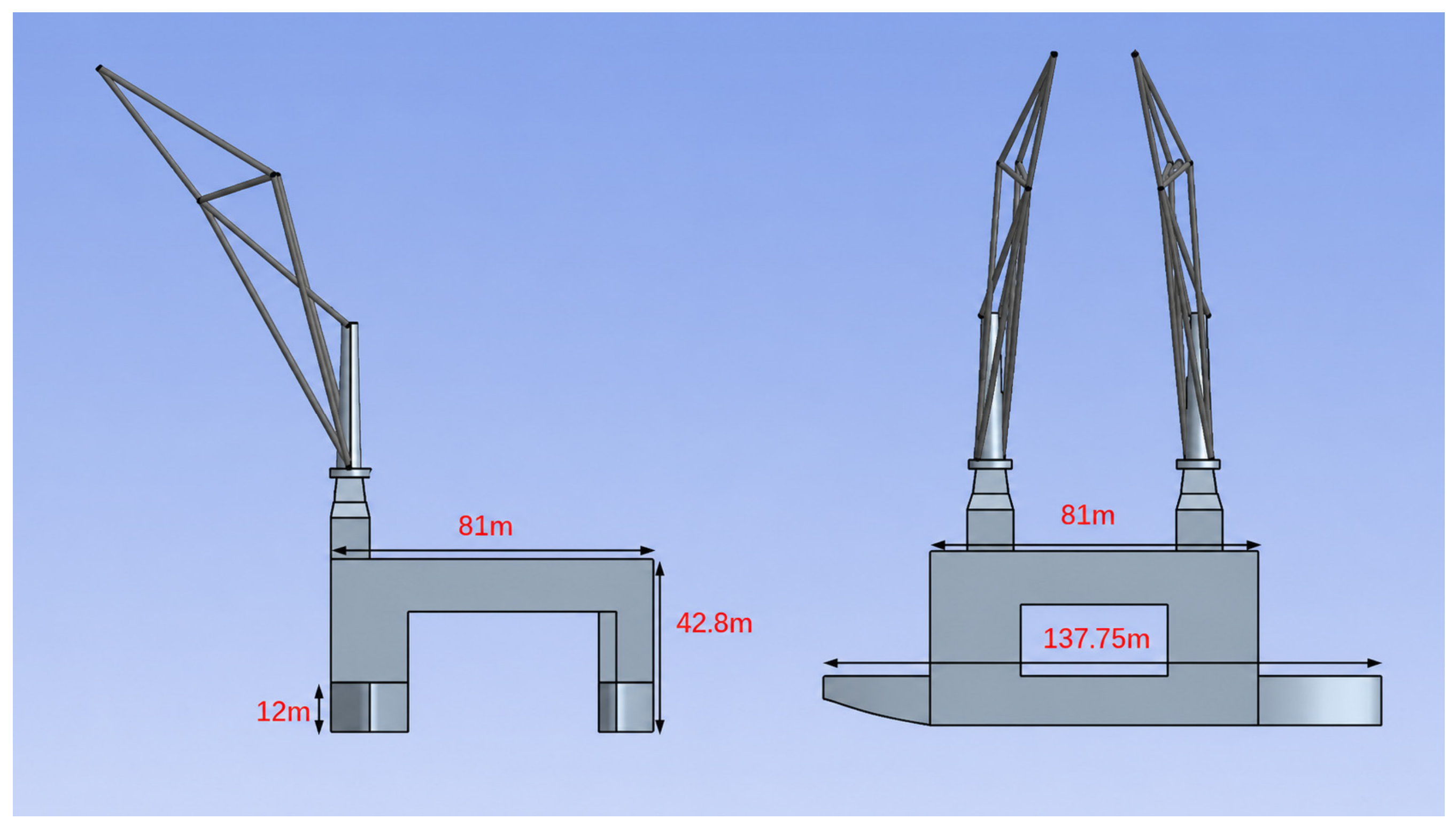
Figure 2 illustrates the definition of the wave incident direction adopted in this study. The origin of the local coordinate system for the SSCV is located at the intersection of the centerline plane (x = 0), design waterline plane (z = 0), and zero station plane (y = 0). The design waterline plane is defined as the z = 0 plane, with the positive z-axis pointing upward. The x-axis is aligned along the ship length direction, with the bow pointing to the positive x-axis. The x and y axes follow the right-hand rule.
Figure 2.
SSCV model and coordinate system.
2.2. Potential Flow Theory
The frequency-domain solution in ANSYS-AQWA [26] is mainly based on the linear Airy wave theory, which is a theoretical framework providing a simplified description of wave surfaces. As a fundamental method for hydrodynamic calculations of large-scale marine structures, the linear wave theory is predicated on the following assumptions: the fluid medium is a homogeneous, incompressible ideal fluid, and the flow field is irrotational. Additionally, the motion response of the floating body adheres to the linear dynamics assumption, characterized as small-amplitude harmonic motion:
2.3. Frequency-Domain Theory
The frequency-domain motion equation of a floating body can be expressed as follows [27]:
where Ms denotes the generalized mass matrix of the floating body, and Cs represents the hydrostatic stiffness matrix; A(ω) and Bs(ω) are the frequency-dependent added mass matrix and radiation damping matrix, respectively; denotes the amplitude spectrum of wave excitation forces; and stands for the Response Amplitude Operator (RAO).
2.4. Time-Domain Analysis
The frequency-domain solution only yields the linear solution of the floating body’s motion in waves. However, for nonlinear loads encountered in actual engineering operations—including mooring loads and lift wire tension—a time-domain motion equation is required for solution, which is commonly solved via the Cummins equation:
In this equation, A(∞) denotes the added mass at infinite frequency; K(t) is the impulse response function, also referred to as the time delay function; Fexc(t) represents the time-varying wave excitation force; and FE(t) denotes the external loads acting on the floating body, including mooring loads, wind loads, and current loads.
2.5. Mooring Loads
In the AQWA dynamic mooring model, each line is divided into elements. The force balance for each element accounts for tension, hydrodynamic forces, and inertia. Equations (6)–(9) describe the mooring element loads with torsional deformation omitted.
where li and di are the length and diameter of the element, respectively; and Ti are the buoyancy, self-weight, and nodal tension at both ends of the element, respectively; Cxi and Cdi are the axial and radial drag coefficients, respectively; Ai and Ni are the unit axial and radial vectors, respectively; Ui(t) is the velocity of the fluid particle at time; and Vi(t) is the velocity of the element node at time.
3. Numerical Simulation Model
This study focuses on an asymmetric SSCV. The vessel is composed of two asymmetrically arranged pontoons (main/auxiliary pontoons), four vertical columns, and a box-type superstructure. Specifically, the main pontoon features midship section symmetric lines, while the bow section of the auxiliary pontoon exhibits asymmetric line characteristics, with no transverse connecting structure between the two pontoons.
The principal dimensions of the SSCV model are listed in Table 1. Based on the model dimensions, the main body of the SSCV was modeled using SolidWorks 2021, and the crane boom section of the semi-submersible platform was constructed in the Design Modeler module in ANSYS 2023R1 Workbench, as illustrated in Figure 3. The lifting points of the two cranes are located at (10, −98.52, 139) and (−10, 35.98, 139), respectively. The boom angle is 59.75°.
Table 1.
Specific parameters of the SSCV model.
Figure 3.
The numerical model of SSCV.
To ensure the accuracy of the numerical model, a model calibration was first conducted prior to the dynamic response analysis of the blade lowering process. The calibration procedure consisted of two steps: the static stiffness characteristics of the mooring system were compared with the theoretical values provided by the design code to validate the basic parameter settings of the finite element model.
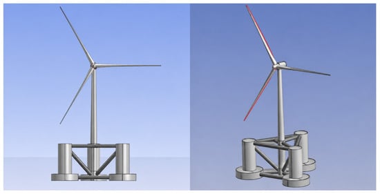
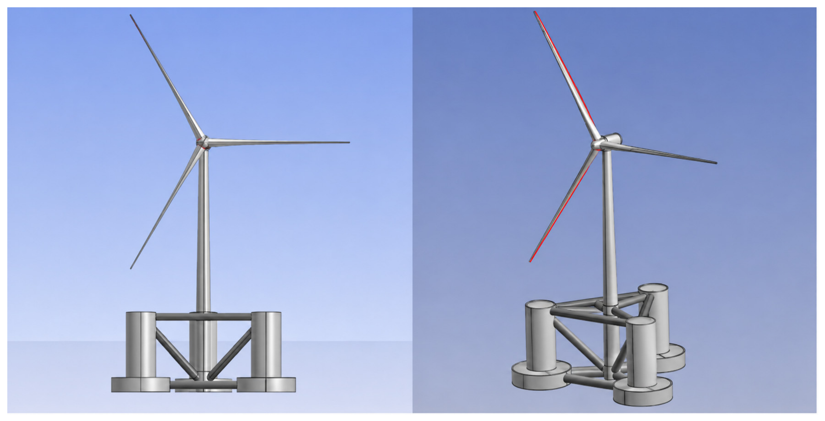
Another research object of this study is the SNL-13.2MW semi-submersible floating wind turbine foundation, which is an extended design based on the OC4 platform (using public data from Sandia National Laboratories). This foundation adopts a central column–three-pontoon structural design, consisting of one main column connected to the tower and three lateral support columns with pontoons [28]. The upper wind turbine employs the publicly available DTU-10MW wind turbine [29], with a blade length of 86.37 m and a hub height of 119 m, and the turbine is mounted on the central main column. Hereinafter, this extended version of the OC4 foundation is referred to as OC4+.
Figure 4 shows the semi-submersible model. Table 2 lists the geometry and the reported draft, displacement, and center-of-gravity position.
Figure 4.
The model of a semi-submersible floating wind turbine.
Table 2.
The parameters of the semi-submersible floating wind turbine.
The upper structure of the floating wind turbine is based on the publicly available DTU-10MW reference model. The blade mass is 41.67 t, and the blade length is 86.37 m. The model of the blade is shown in Figure 5, and its detailed parameters are listed in Table 3.
Figure 5.
The model of the blade.
Table 3.
The parameters of the blade.
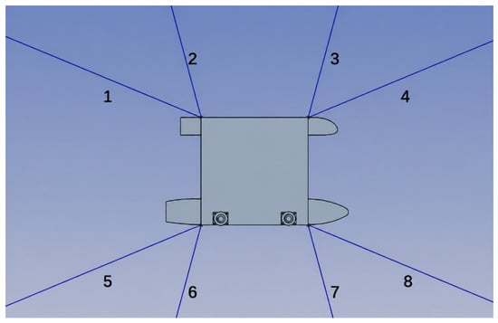
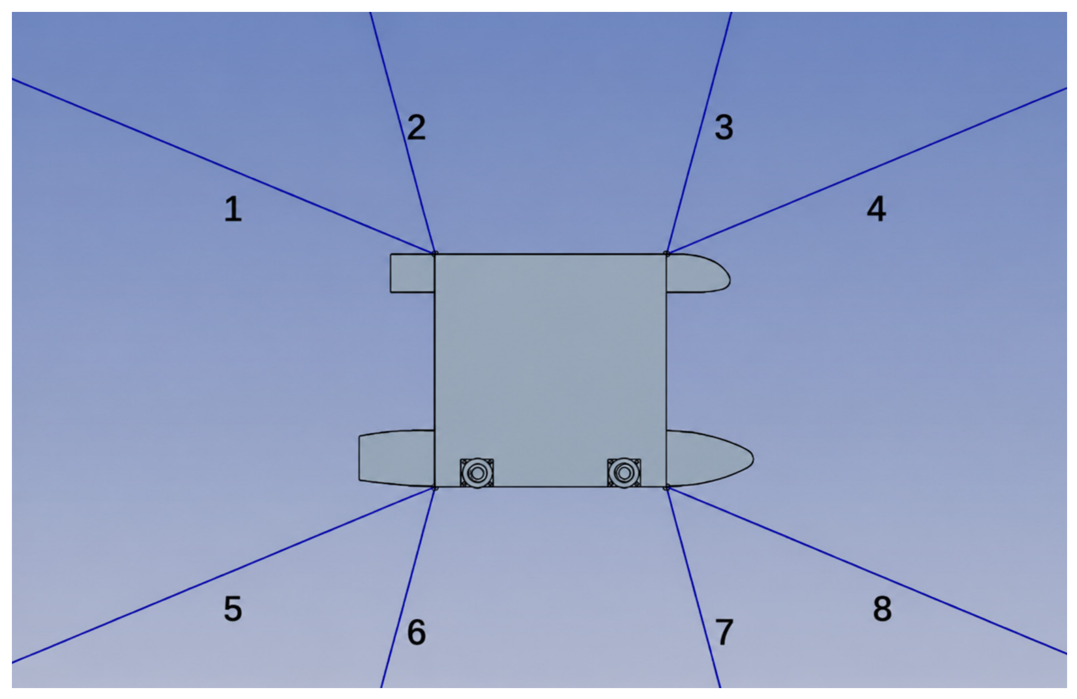
This study considers an operational water depth of 100 m in a deep-sea environment and selects one positioning method: mooring positioning. The mooring system employs a symmetric configuration consisting of eight catenary mooring lines arranged around the platform. The lines are grouped in pairs, with an intra-group separation of 52.5° between the two lines in each pair. There are four such groups in total, spaced at 82.5° intervals from each other. Each mooring line has a length of 500 m. The top end of each line is connected to the outer bottom of the column on the SSCV, while the bottom end is attached to a seabed anchor. The layout of the mooring system is illustrated in Figure 6, and the detailed parameters of the mooring lines are provided in Table 4.
Figure 6.
The mooring schematic diagram of the SSCV.
Table 4.
The material parameters of the mooring lines.
4. Frequency-Domain Analysis
4.1. Mesh Convergence Analysis
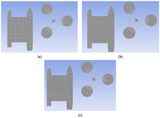
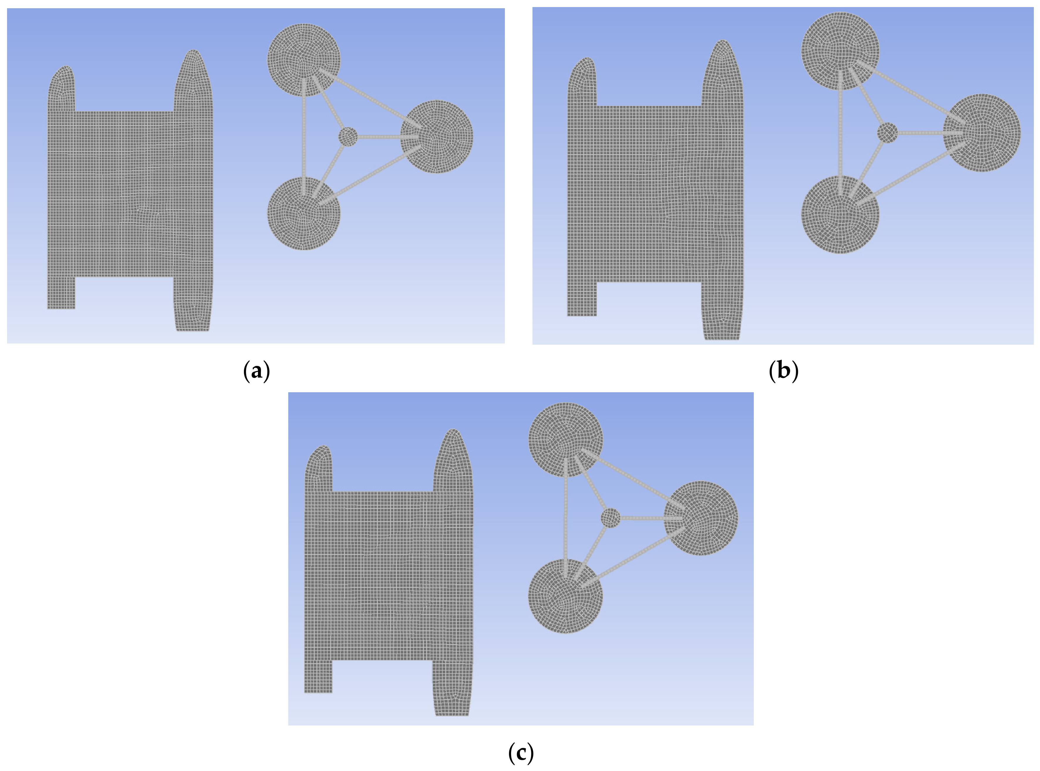
The hydrodynamic analysis in AQWA is based on the panel method within potential flow theory, and its computational accuracy is closely related to the quality of mesh discretization. The coordinate system of the coupled system follows the convention shown in Figure 7. The positive x-axis points from the stern to the bow of the semi-submersible crane vessel (SSCV), and the positive y-axis points from the floating offshore wind turbine (FOWT) toward the SSCV. The separation between the two floating bodies is 35.35 m. In the solution procedure, the wetted surface must first undergo mesh discretization. Appropriate mesh size and quantity must be selected to ensure the accuracy of the hydrodynamic calculation results. This study analyzes three mesh sizes: 1.4 m, 1.5 m, and 1.6 m. The boundary element model for each computational model is shown in Figure 7. In accordance with the requirements of a mesh convergence study, three distinct discretization scales were selected for comparative calculation. The frequency range of computation was set from 0 to 2.2 rad/s.
Figure 7.
Models under different mesh sizes: (a) 1.4 m mesh size; (b) 1.5 m mesh size; (c) 1.6 m mesh size.
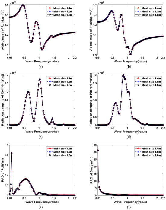
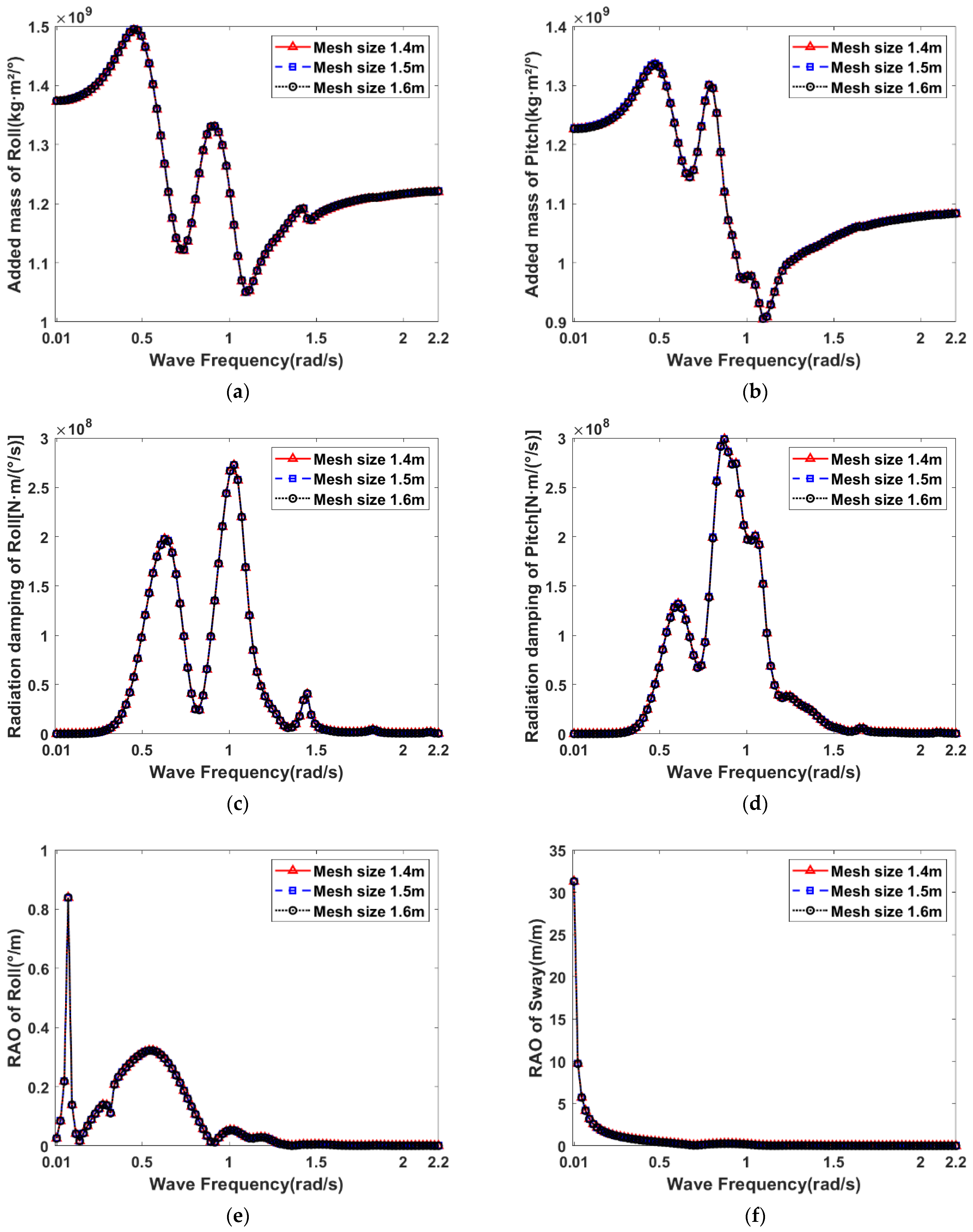
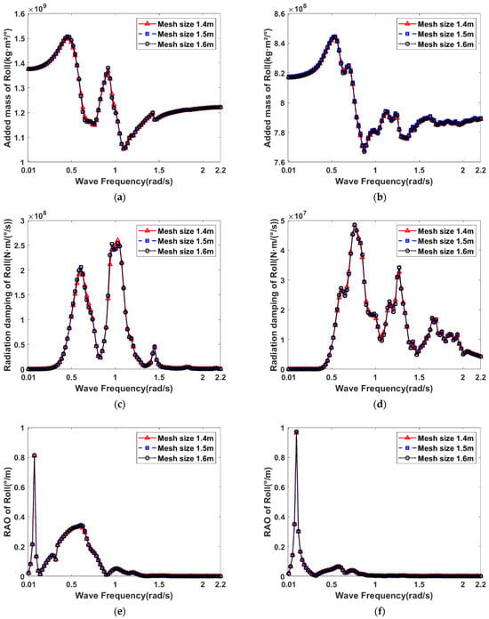
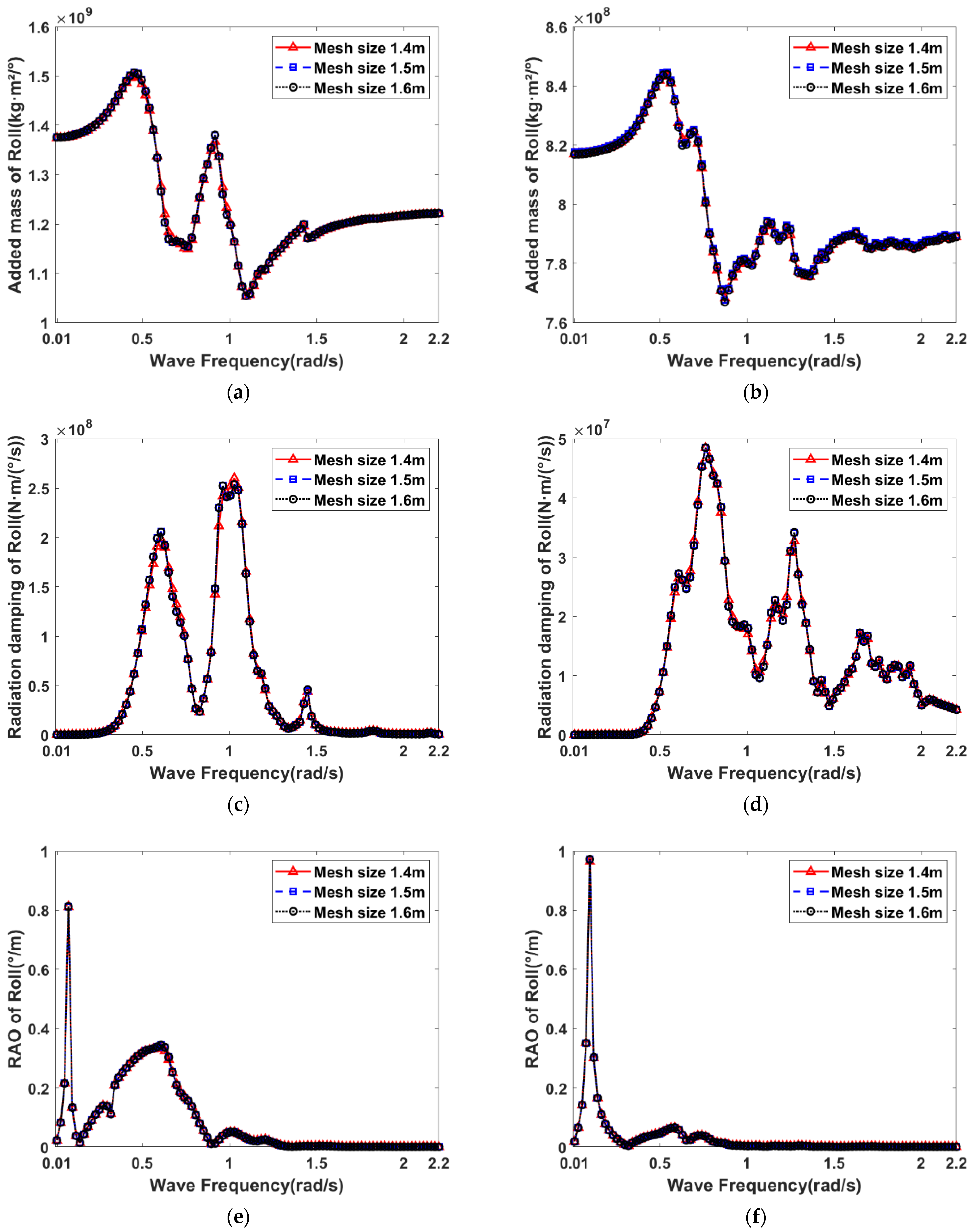
Figure 8 and Figure 9 present the hydrodynamic results of the standalone semi-submersible platform and the system composed of the crane vessel and the floating wind turbine under three mesh sizes, respectively. By comparing the hydrodynamic results calculated with the three mesh sizes, the mesh convergence can be investigated. Figure 8 illustrates the comparative hydrodynamic results of the semi-submersible platform under the three mesh division schemes, with a focus on analyzing the added mass coefficients, radiation damping coefficients, and Response Amplitude Operators (RAOs) in the roll and pitch degrees of freedom. The results indicate that the calculations under different mesh sizes exhibit good consistency, and the three curves show consistent trend characteristics. Figure 9 presents the comparative hydrodynamic results of the semi-submersible platform and the floating wind turbine in the combined system under the three mesh sizes. Similarly, the calculation result curves of the three groups with different mesh sizes show consistent trend characteristics, with small deviations among the parameter points. Considering that the difference between the calculation results of the 1.4 m and 1.5 m mesh sizes is within an acceptable range, and balancing computational efficiency and accuracy, this study ultimately selects the 1.5 m mesh size for subsequent frequency-domain hydrodynamic analysis. This selection reduces the computational time by approximately 25% compared with the 1.4 m mesh scheme.
Figure 8.
Comparison of hydrodynamic coefficients of SSCV under different mesh sizes: (a,c,e) the added mass, radiation damping, and RAO of the SSCV in the roll direction; (b,d,f) the added mass, radiation damping, and RAO of the SSCV in the pitch direction.
Figure 9.
Comparison of hydrodynamic coefficients of the multi-body System under different mesh sizes: (a,c,e) the added mass, radiation damping, and RAO of the SSCV in the roll direction; (b,d,f) the added mass, radiation damping, and RAO of the FOWT in the roll direction.
4.2. Hydrodynamic Analysis of SSCV and FOWT
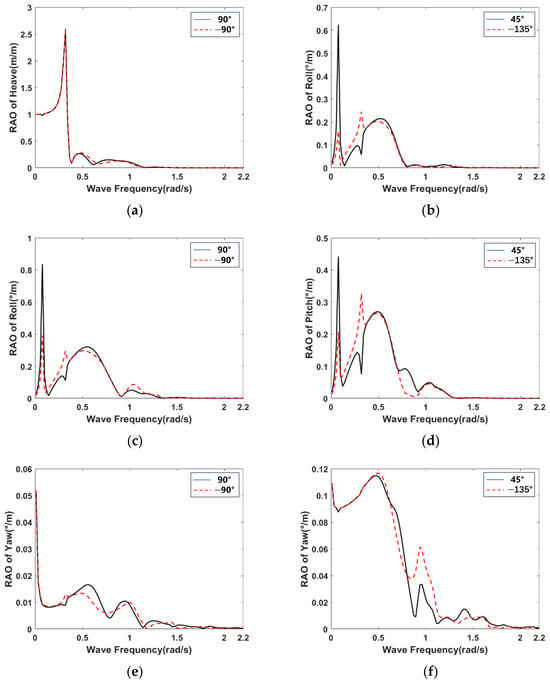
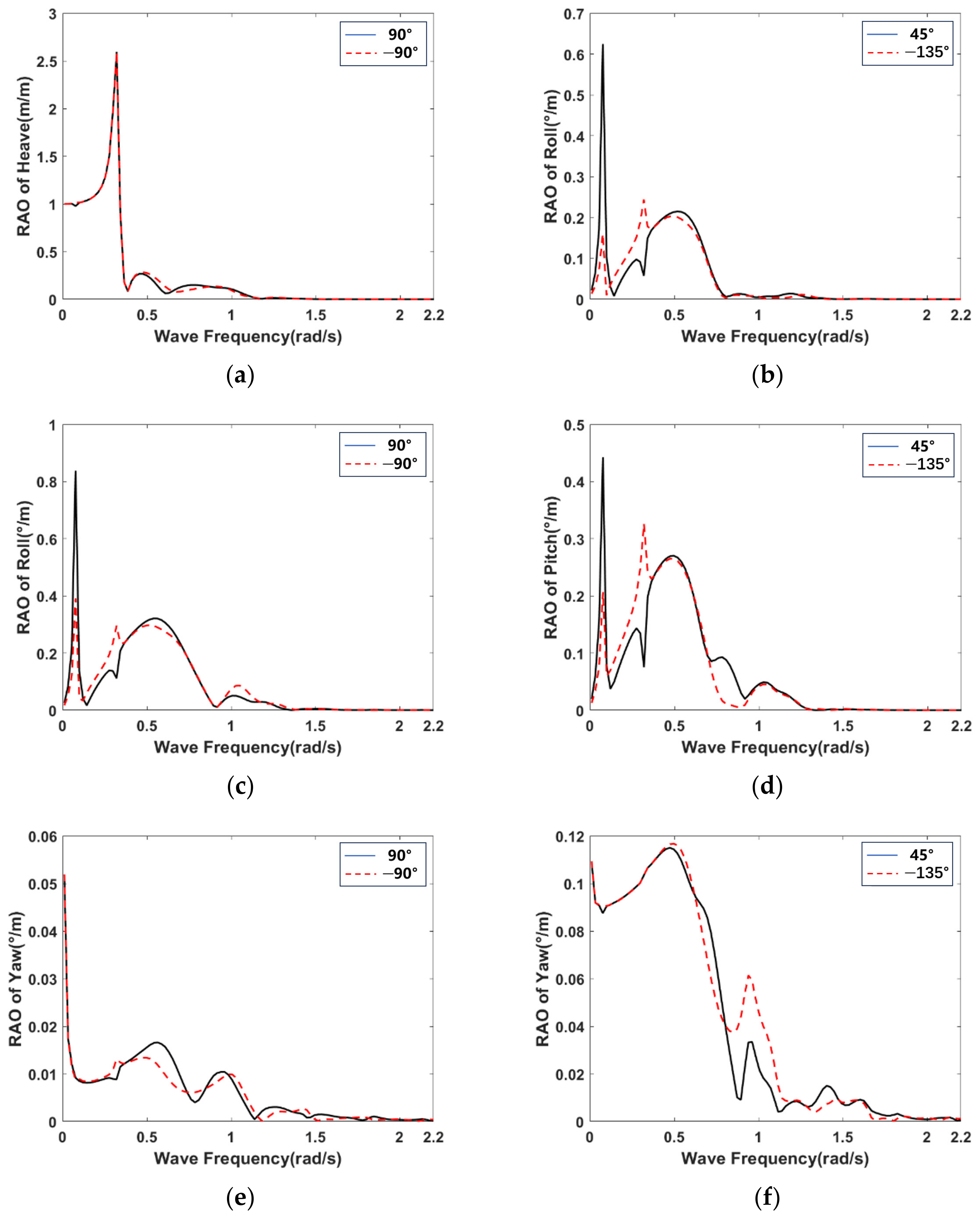
When two or more floating bodies are at a relatively close distance, the wave shielding effect usually occurs [27]. This section investigates the hydrodynamic characteristics of the SSCV and the floating wind turbine. Their hydrodynamic results are presented in Figure 10, Figure 11 and Figure 12. Figure 10 shows a comparison of the crane vessel’s frequency-domain RAOs (Response Amplitude Operators) under two sets of opposing wave directions: 90° and −90°, and 45° and −135°. Due to the asymmetric structure of the vessel’s hull form, particularly its underside, the RAOs differ even for these opposing wave directions. While the RAOs in the surge direction show little difference between the 90° and −90° cases, notable discrepancies are observed in the roll and yaw responses. For example, at an angular frequency of 0.3 rad/s, the response amplitude operator (RAO) shown in Figure 10d decreases from 0.32°/m to 0.07°/m. Similarly, for the 45° and −135° directions, the results differ across the roll, pitch, and yaw degrees of freedom. These variations are entirely attributable to the vessel’s asymmetric structural design.
Figure 10.
The RAO results of the SSCV: (a,c,e) the comparison of RAO results of the SSCV under the 90° and −90° wave directions; (b,d,f) the comparison of RAO results of the SSCV under the 45° and −135° wave directions.
Figure 11.
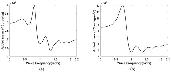
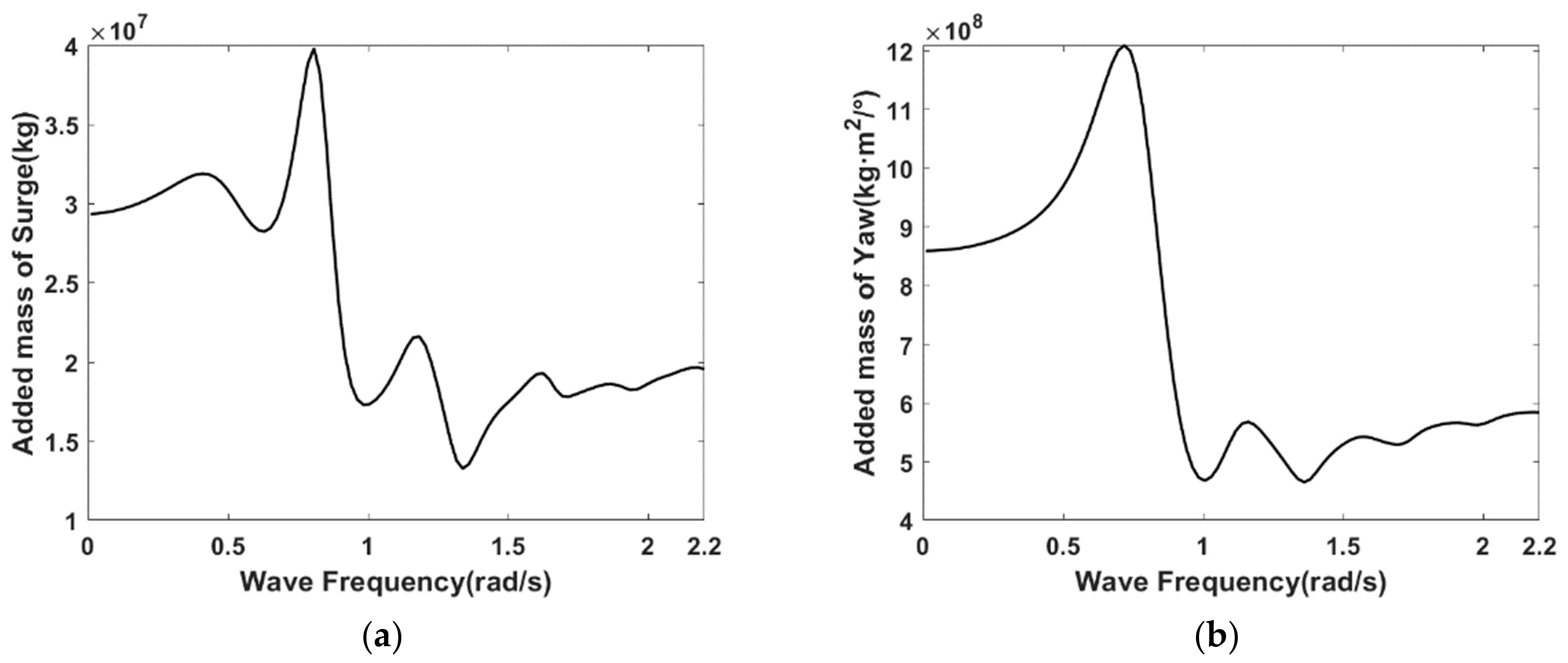
The added mass results of the floating wind turbine: (a) the added mass in surge degree; (b) the added mass in yaw degree.
Figure 12.
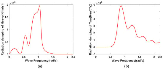
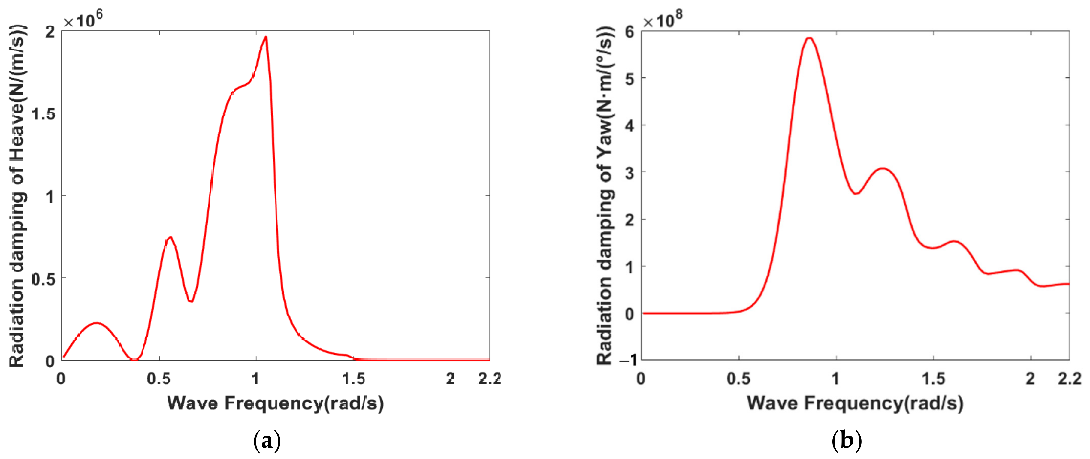
The radiation damping results of the floating wind turbine: (a) radiation damping in surge degree; (b) radiation damping in yaw degree.
Figure 11 and Figure 12 present the added mass and radiation damping results for the floating wind turbine. From the results, it can be observed that the added mass exhibits a trend of initially increasing, then decreasing, and finally converging to a constant value. The added mass in the surge direction stabilizes at approximately 2 × 10⁷ kg. Regarding the radiation damping, the results show a trend of first increasing, then decreasing, and ultimately approaching zero, which aligns with the characteristic behavior of added mass and radiation damping.
4.3. Roll Damping Correction
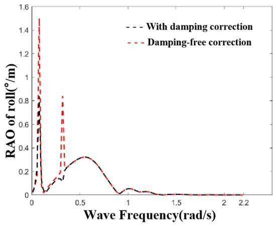
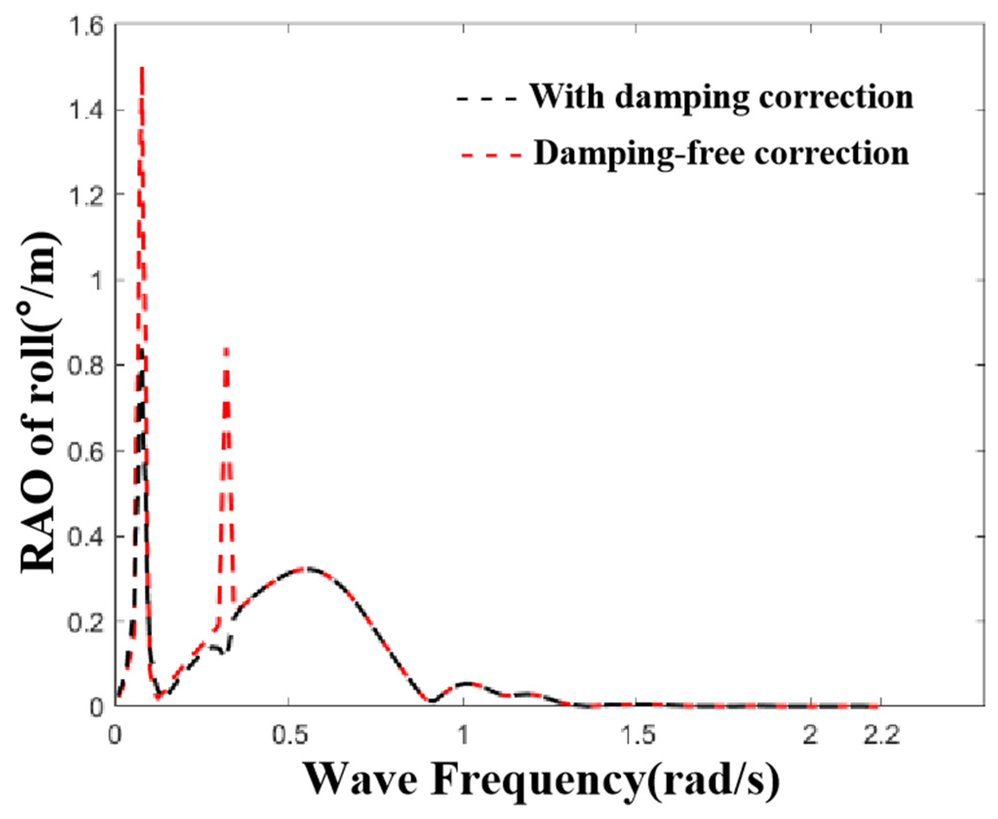
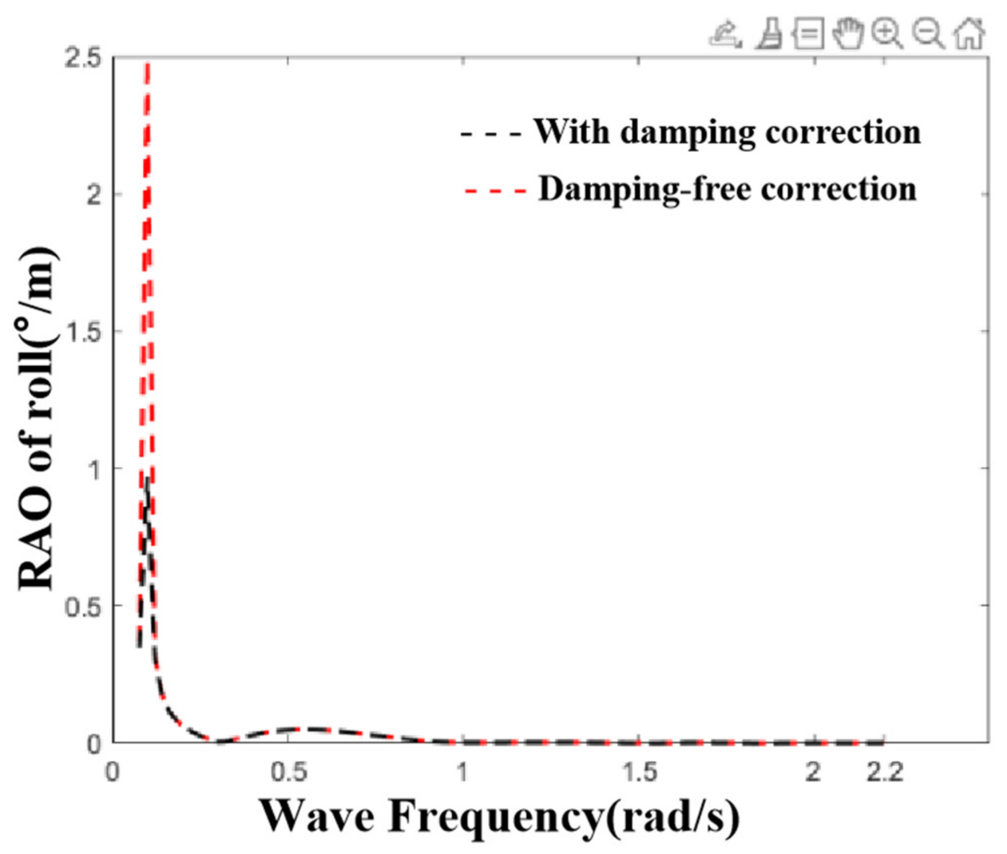
Although ANSYS AQWA can efficiently calculate the hydrodynamic characteristics of floating bodies under different wave frequencies using potential flow theory, its inviscid fluid assumption may lead to unrealistic fluid resonance and cannot accurately account for viscous and strong nonlinear effects. Therefore, roll damping correction is required before hydrodynamic analysis.
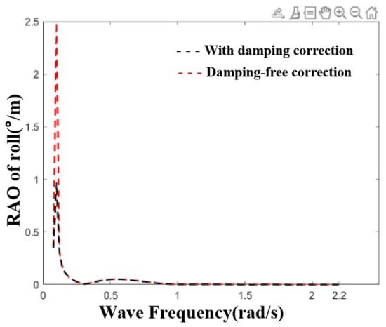
The floating wind turbine and semi-submersible lifting platform were separately damped. According to the ship design report, a correction value of 4% of the critical damping can be adopted for the damping correction. For the floating wind turbine, an additional damping correction value of 8% of the critical damping was used. The critical damping in the Rx direction for the lifting platform and the floating wind turbine was calculated based on the additional mass under the natural period, which was 1,817,000,000 N·m/(rad/s) and 8,530,000,000 N·m/(rad/s), respectively. The effects of the damping correction for the lateral oscillation are shown in Figure 13 and Figure 14.
Figure 13.
The graphical representation of the roll damping correction for the SSCV.
Figure 14.
The graphical representation of the roll damping correction for the FOWT.
5. Dynamic Response Analysis of the Blade Lowering Operation
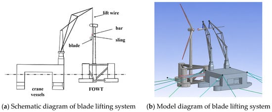
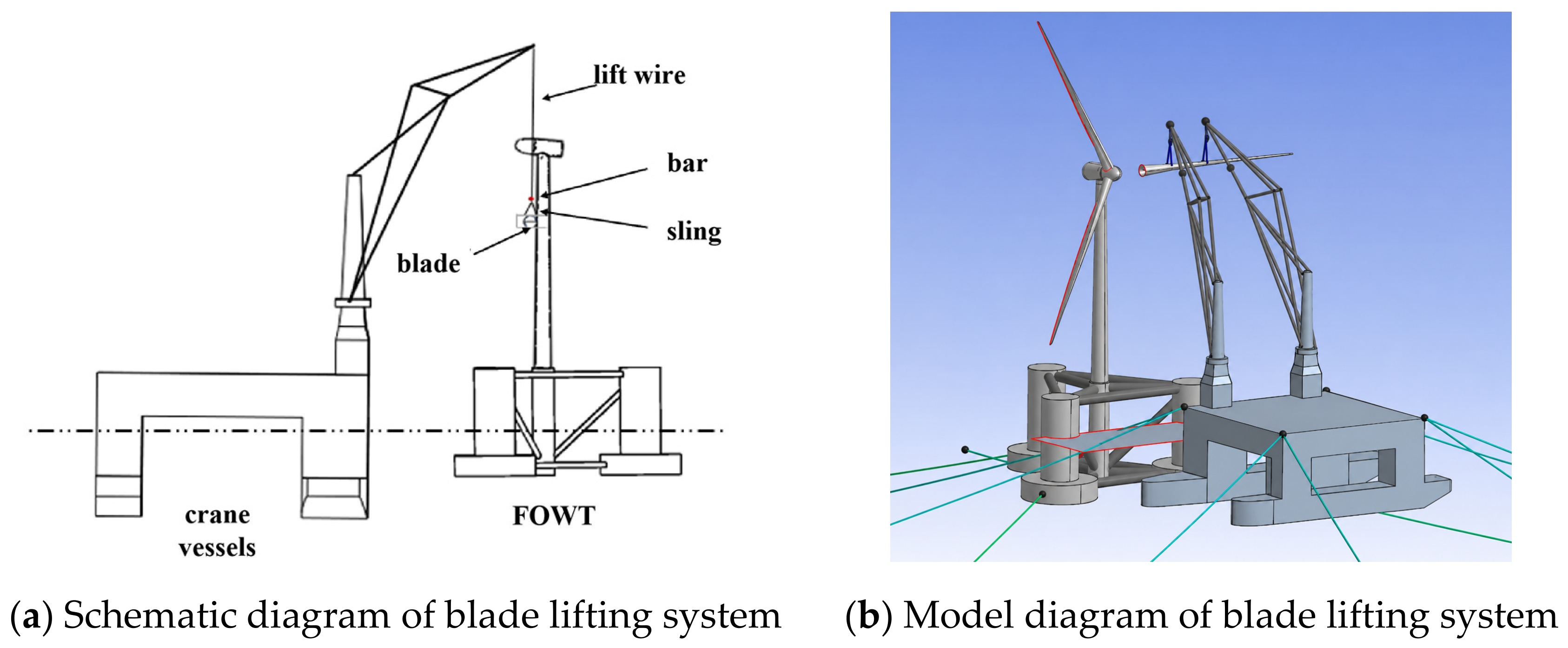
The SSCV investigated in this study is equipped with two cranes, each utilizing a main hook. The blade lowering operation involves the SSCV, the floating wind turbine, and the blade, as well as the connecting mooring systems, lifting appliances, and sling systems, shown in Figure 15 and Table 5. The following simplification strategy was adopted for numerical modeling: the hook and the boom were integrated into a single rigid body element, and the mass of the yoke was coupled to the blade model via a mass point.
Figure 15.
Blade lifting schematic diagram.
Table 5.
Lifting sling parameters.
The crane vessel studied in this chapter employs the mooring system determined in the previous section. The floating wind turbine employs a 3-point mooring system, with its fairleads located at the outer extension of the base column of the foundation.
This section analyzes the dynamic process of lowering a removed blade onto the deck of an SSCV following blade replacement. Three different values of lift wire stiffness and lowering velocity were selected to investigate their influence on the blade alignment process. The analysis was conducted under a wave condition characterized by a significant wave height of 1.5 m, a spectral peak period of 6 s, and a peak enhancement factor γ of 3.3. The simulation used a time step of 0.04 s for a total duration of 9000 s. To account for wind speed variation at different heights, the wind condition was defined by the NPD spectrum with a wind speed of 12 m/s at a 10 m reference height. This setup enables a thorough evaluation of the effects of environmental loads on the operation.
5.1. Comparison of the Stiffness of Sling
To investigate the influence of sling stiffness on the dynamic response of the blade, the sling tension, and the lift wire tension during the lowering operation, this section examines three different sling stiffness values for analysis, as specified in Table 6. A dynamic time-domain analysis was conducted using slings of these three stiffness levels, and the results are presented in the figures below.
Table 6.
Three types of slings and corresponding stiffness.
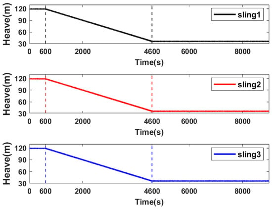
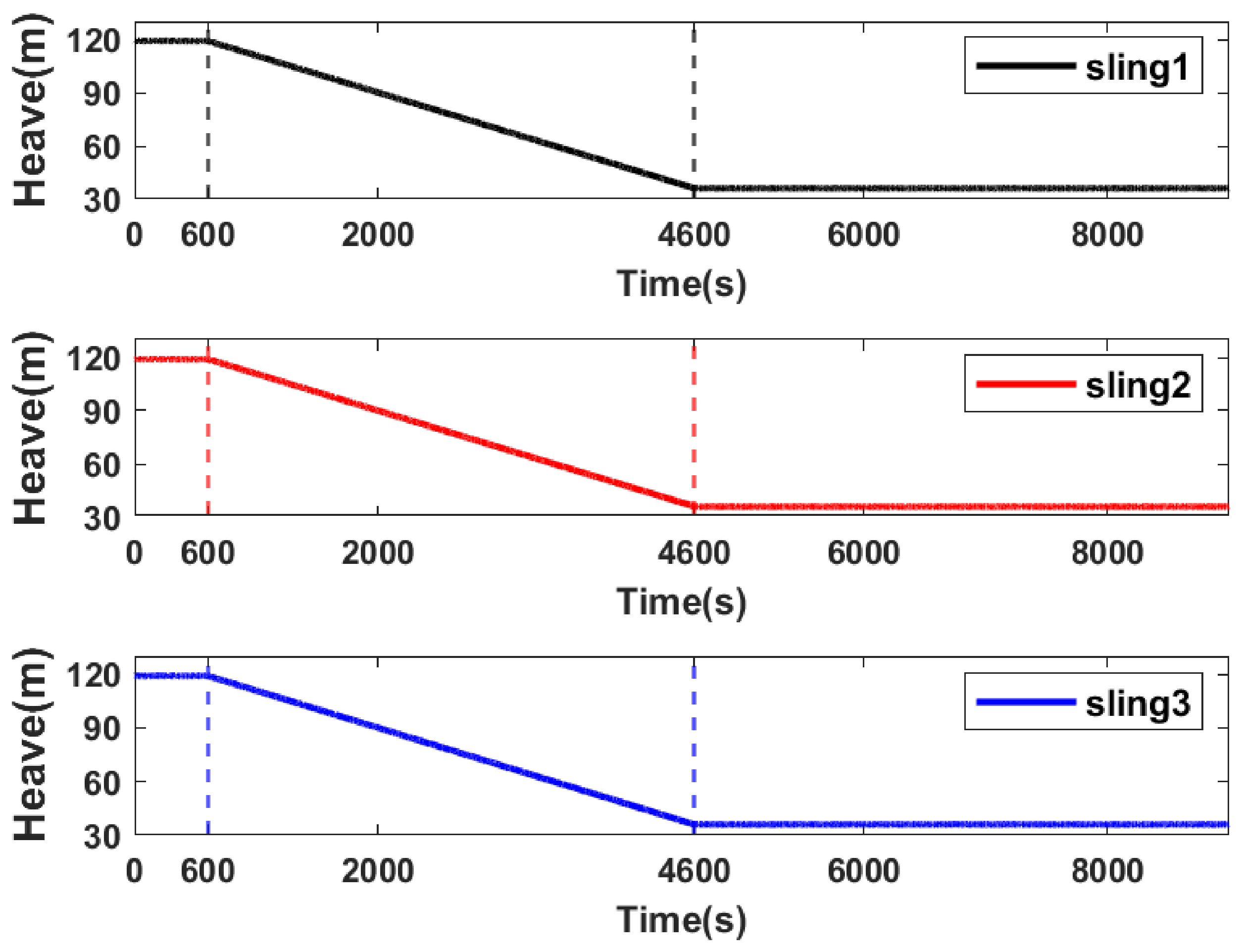
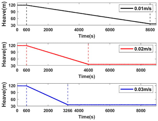
A lowering operation velocity of 0.02 m/s was selected. As can be seen from Figure 16, the lowering process commenced at 600 s and concluded at 4600 s under all three conditions, lasting 4000 s. This study further designates 600 s as key position KP-1 and 4600 s as key position KP-2. A comparative analysis of the sling tension, lift wire tension, and blade dynamic response at these key positions is conducted.
Figure 16.
Heave motion response time series of the blade during the entire lowering operation.
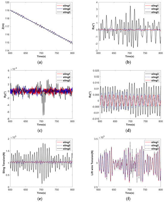
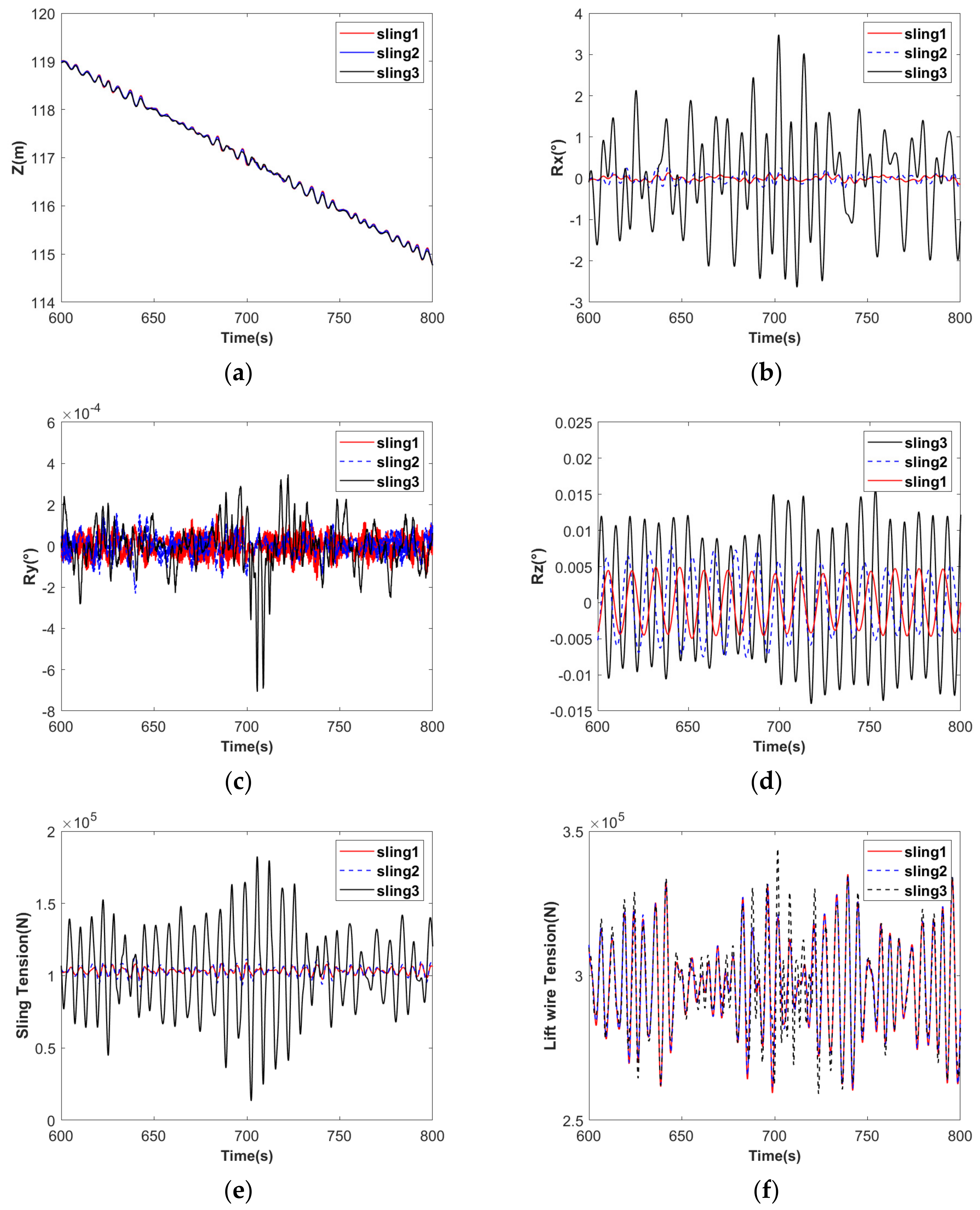
Figure 17 presents the response of the blade’s vertical dynamics, roll, pitch, yaw, sling tensions, and lift wire tension during the time period from 600 s to 800 s. Regarding the blade’s dynamic responses in the three rotational directions, the responses of Sling 1 and Sling 2 are similar but distinctly different from those of Sling 3. The blade exhibits more severe roll motion when Sling 3 is employed. As shown in Figure 18b, around 700 s during the lowering operation with Sling 3, the maximum roll response of the blade reaches 3.6°. In the absence of a criterion specific to offshore blade lifting, a criterion developed for offshore lifting of large structures was used as a reference. According to the Noble Denton guidelines [30], the maximum allowable roll angle for large structures during installation should be less than 2°. Therefore, the configuration with Sling 3 fails to meet this requirement, whereas those with Sling 1 and Sling 2 are acceptable. Further analysis of Figure 18e,f indicates that when Sling 3 is used, its maximum tension reaches 1.81 × 10⁵ N at 700 s. In contrast, the maximum tensions for Sling 1 and Sling 2 are only 1.1 × 10⁵ N. The lift wire tensions under the three sling configurations are comparable; however, the tension in Sling 3 is significantly higher than those in the other two configurations.
Figure 17.
Blade motion response and tensions of slings and lifting cables at the KP-1 position: (a) heave motion; (b) roll motion; (c) pitch motion; (d) yaw motion; (e) sling tension; (f) lift wire tension.
Figure 18.
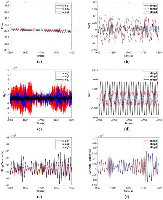
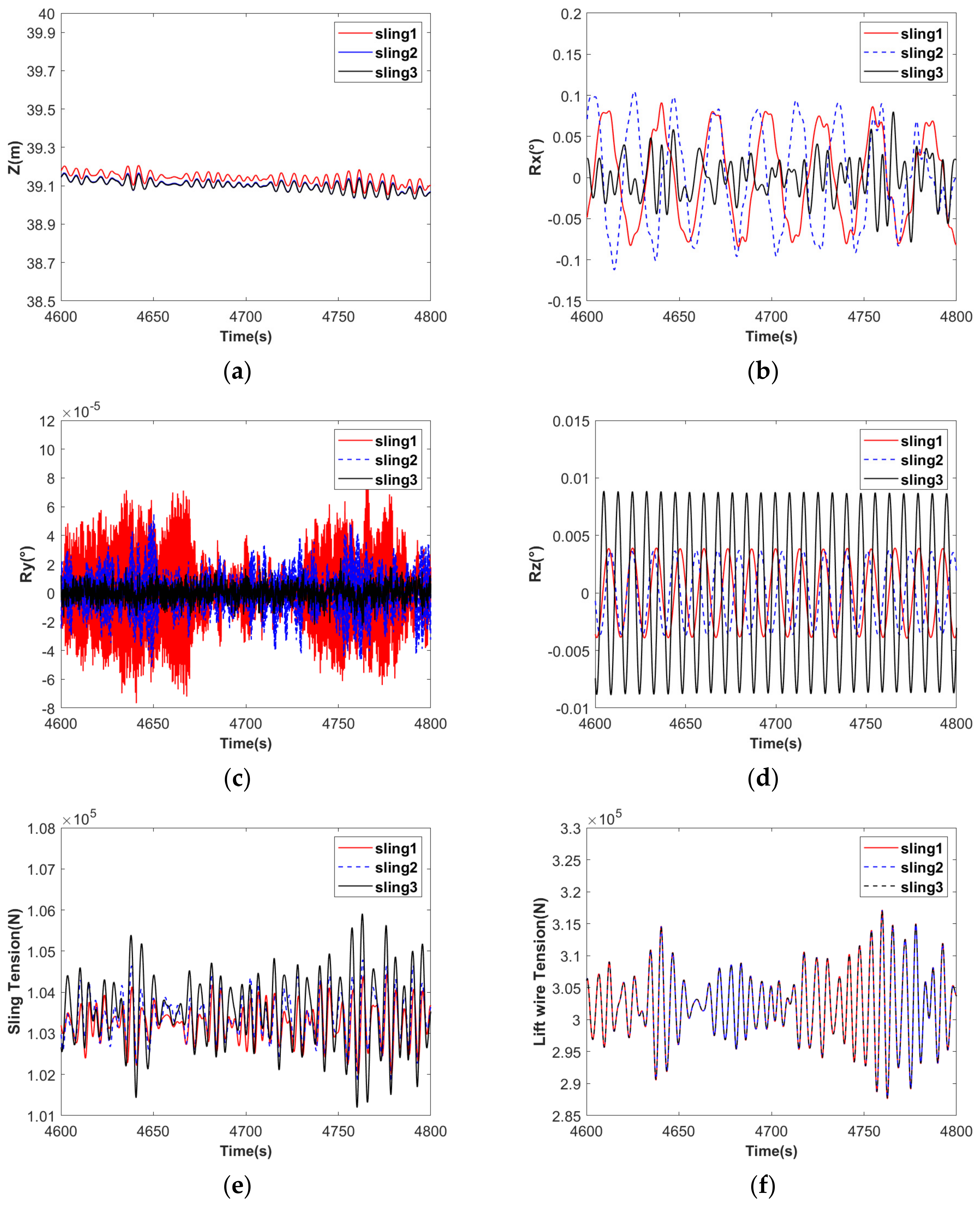
Blade motion response and tensions of slings and lifting cables at the KP-2 position for different sling stiffness values: (a) heave motion; (b) roll motion; (c) pitch motion; (d) yaw motion; (e) sling tension; (f) lift wire tension.
Figure 18 illustrates the response time histories of the blade’s heave, roll, pitch, and yaw motions, as well as the sling tension and lift wire tension, during the time interval from 4600 s to 4800 s. The instant of 4600 s corresponds to the completion of the blade lowering operation, at which point the blade’s vertical position is approximately 39 m. The period from 4600 s to 4800 s represents a 200 s duration post-lowering, during which the blade’s dynamic responses stabilize. As shown in the six subplots, the amplitudes of roll, pitch, and yaw motions are relatively small under all three sling stiffness conditions, with discernible variations in the response characteristics among the different conditions. Compared to the initial lowering phase (600 s to 800 s), the blade exhibits the smallest motion under the Sling 3 condition and the largest under the Sling 1 condition. According to the sling tension plot, the maximum tension under the Sling 3 condition is approximately 1500 N larger than that under the Sling 1 condition. In contrast, the lift wire tension shows no significant difference across the three sling stiffness conditions.
5.2. Comparison of the Lift Speed of Lift Wire
To investigate the influence of the lowering velocity on the lowering operation, and building upon the foundation established in Section 5.1, the sling model Sling 1 was selected. Three distinct lowering velocities were subsequently chosen for further analysis, as detailed in Table 7.
Table 7.
Three types of lift wire speeds.
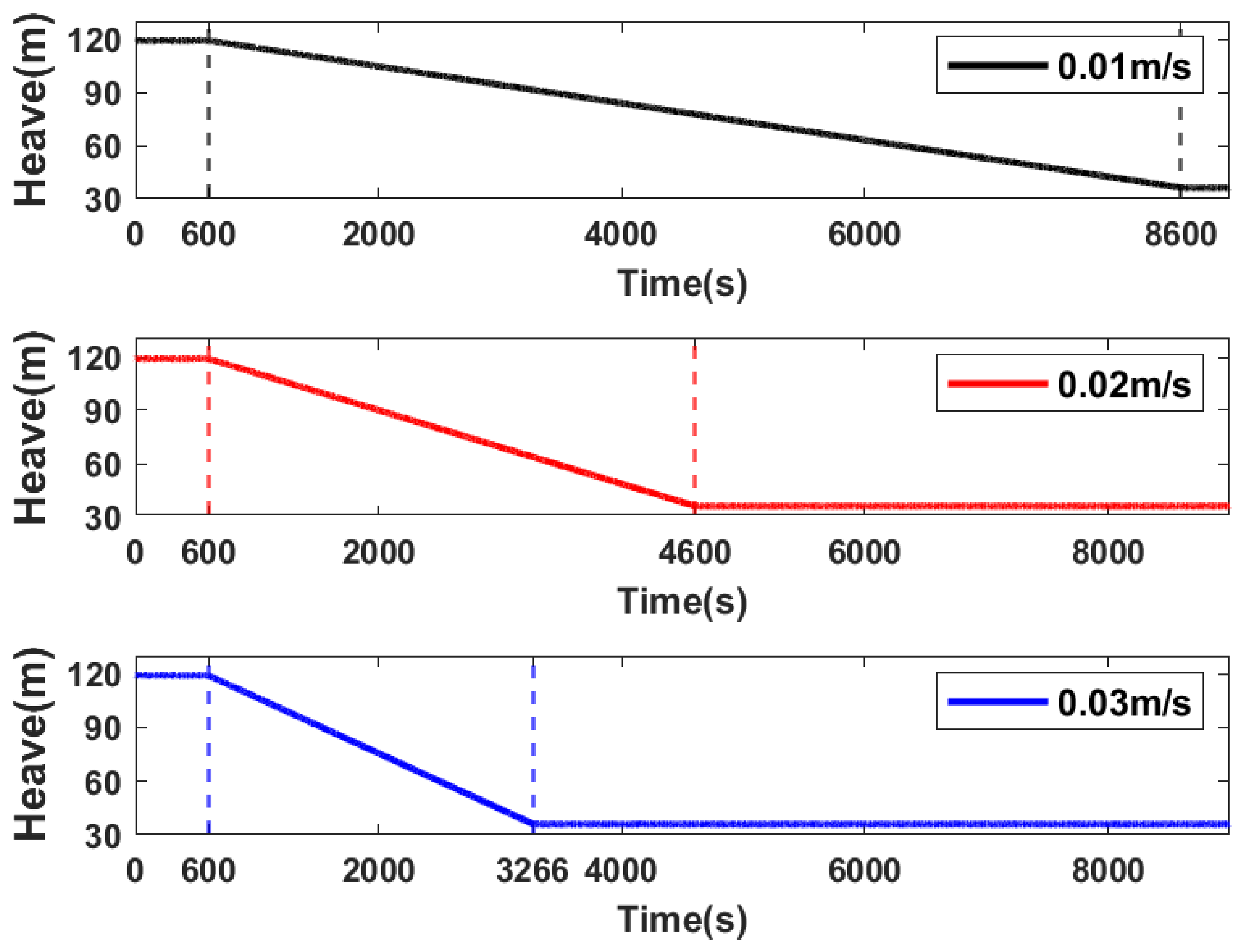
Figure 19 presents the time history curves of the blade’s center of gravity in the vertical direction during the entire lowering operation at three different lowering velocities. As shown in the figure, for all three cases, the lowering operation commences at the same time (600 s). However, due to the different lowering velocities, the times required to reach the target depth vary. The dashed lines in the figure indicate the start time of the operation and the time to reach the designated position. At a lowering velocity of 0.01 m/s, the blade reaches the target depth at 8600 s, resulting in a total operation duration of 8000 s. When the velocity is 0.02 m/s, the target depth is achieved at 4600 s, with a total duration of 4000 s. At 0.03 m/s, the position is reached at 3266 s, corresponding to a total duration of 2666 s. The figure also demonstrates that the cable winch successfully executed the blade lowering procedure.
Figure 19.
Heave motion response time series of the blade during the entire lowering operation.
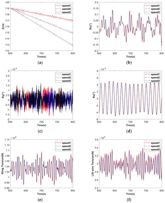
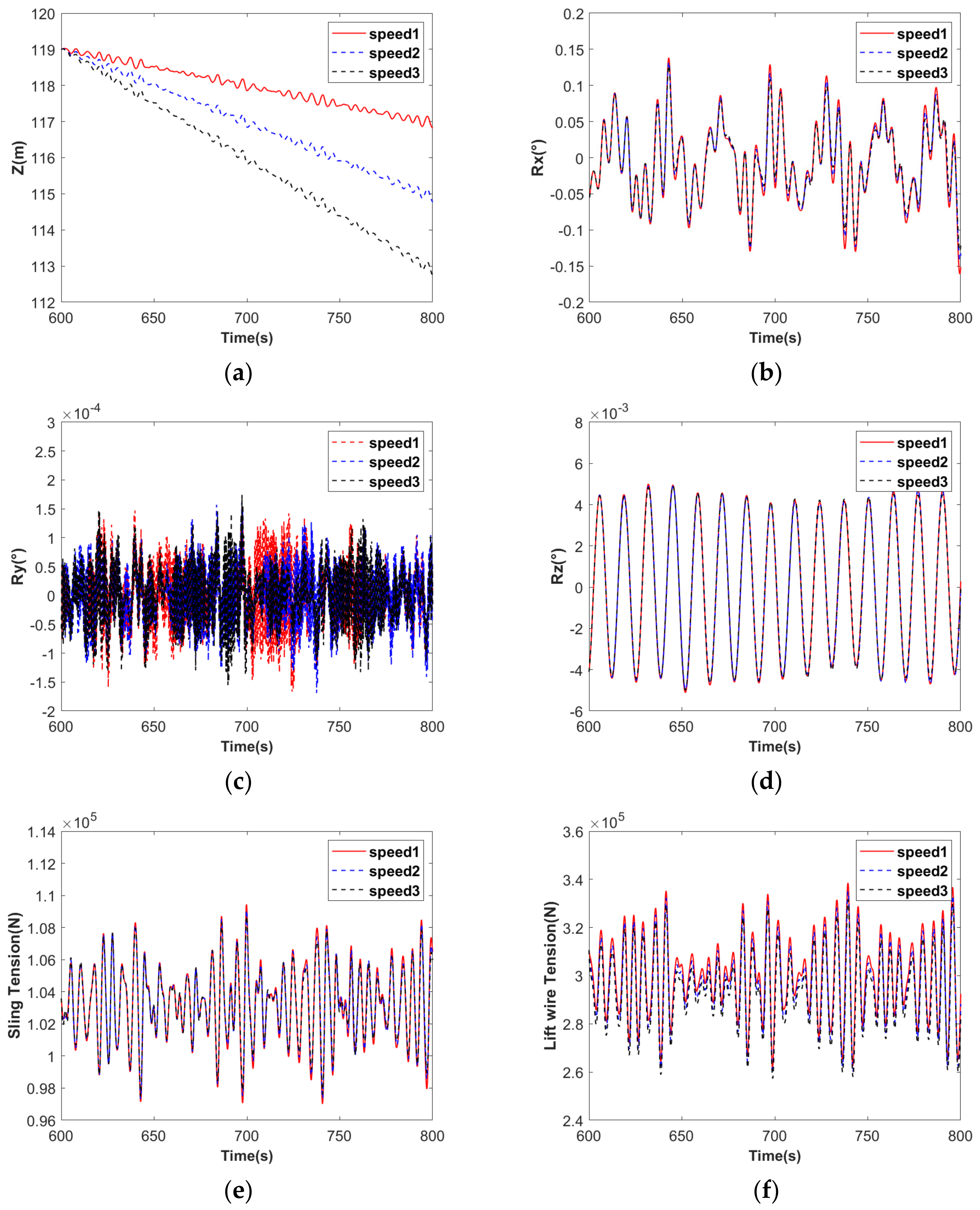
Figure 20 presents the results of blade dynamic response, sling tension, and lift wire tension during the 600–800 s time interval. From Figure 20a, the variation in the vertical position of the blade under three different lowering velocities can be clearly observed during this period. No significant differences were observed in the dynamic responses of the blade along the roll and yaw directions or in the sling tension. The blade pitch response varies considerably across the three lowering-speed cases. Among the cases examined, Speed 3 exhibits a relatively small pitch response. In the lift wire tension plot, with an increase in lifting velocity, the mean tension exhibited a decreasing trend.
Figure 20.
Blade motion response and tensions of slings and lifting cables at the KP-1 position: (a) heave motion; (b) roll motion; (c) pitch motion; (d) yaw motion; (e) sling tension; (f) lift wire tension.
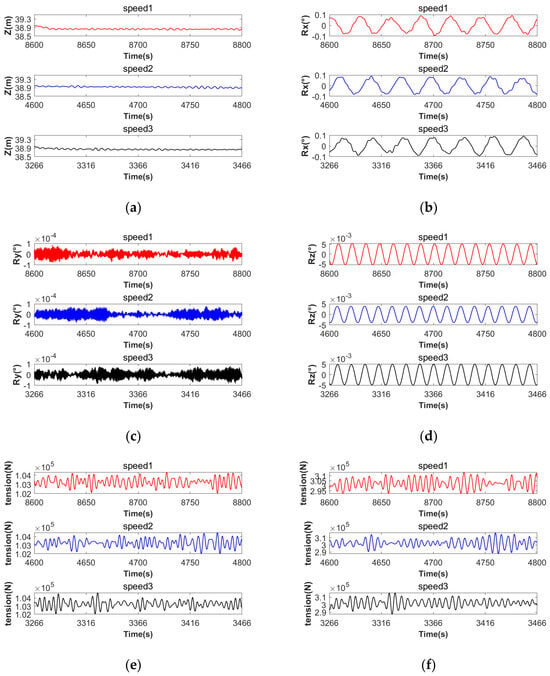
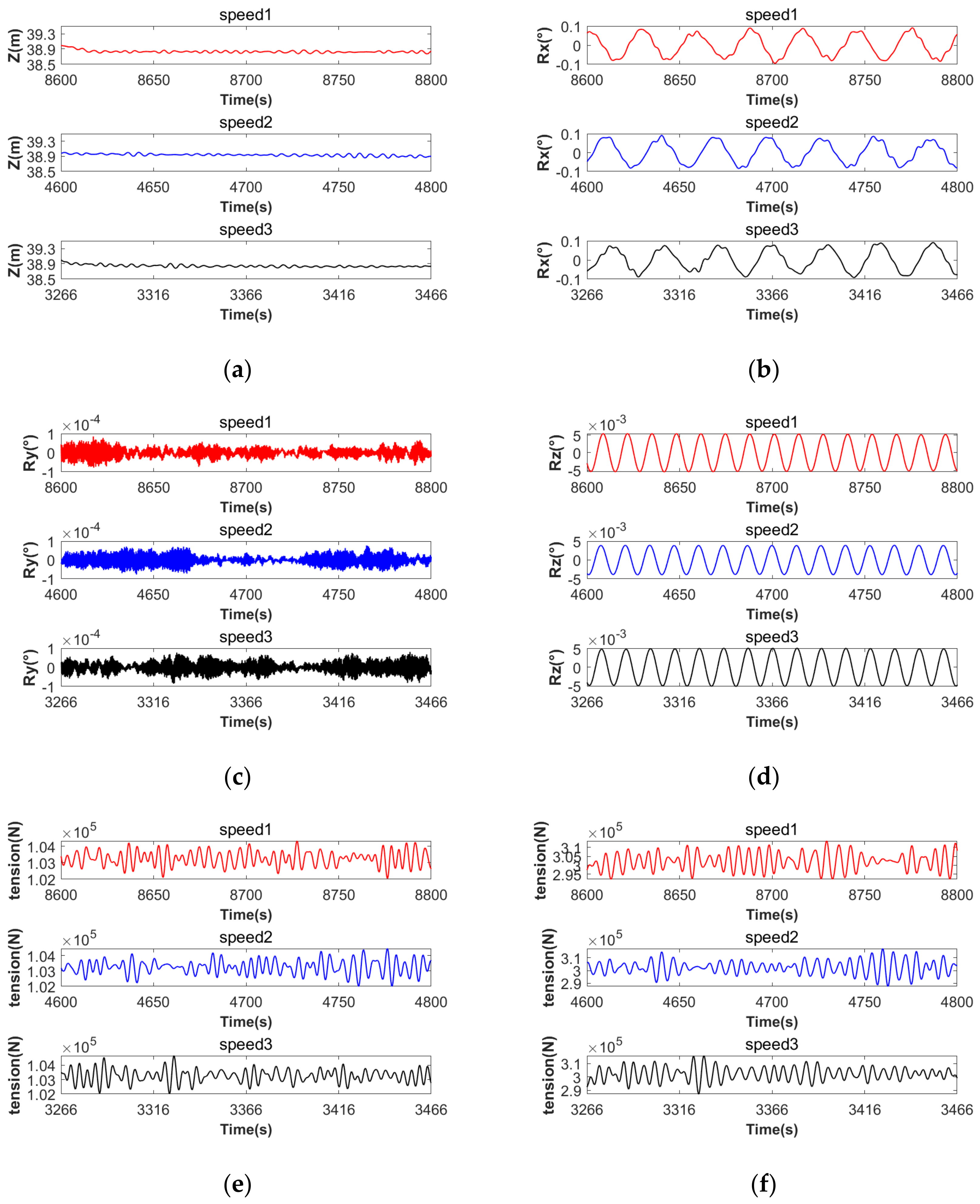
Figure 21 presents the results of blade motion response, sling tension, and lift wire tension under three different lifting velocities. From Figure 21a, it can be observed that the final vertical position of the blade is 39 m under all three lifting velocities, which is consistent with the results obtained under the three sling stiffness conditions. No significant differences are discernible across the six sub-figures, indicating that under the Sling 1 configuration, the influence of the three lifting velocities on the blade motion response, sling tension, and lift wire tension is minimal. This is because the lowering of the blades is a purely vertical, uniform, and straight-line motion, decoupled from roll, pitch, and yaw. Therefore, changes in the vertical velocity cannot cause the blade oscillations to intensify, and the blade has no additional inertial impact loads. The tension of the lifting/suspension cables is solely determined by the blade’s weight and minor environmental dynamic loads and is independent of the lowering speed. Floating wind turbines in the deep sea have a short operation window period and high costs. Within the safety regulations, a medium–high speed lowering (0.02–0.03 m/s) can be adopted to significantly shorten the operation time and reduce the operation costs and the risks associated with sea conditions.
Figure 21.
Blade motion response and tensions of slings and lifting cables at the KP-2 position for different lifting speed: (a) heave motion; (b) roll motion; (c) pitch motion; (d) yaw motion; (e) sling tension; (f) lift wire tension.
6. Conclusions
This study mainly focuses on the offshore in situ large-component replacement operations of floating offshore wind turbines (FOWTs). It focuses on researching the respective hydrodynamic characteristics of the floating offshore wind turbine (FOWT) and the semi-submersible crane vessel (SSCV), as well as the hydrodynamic characteristics of the multi-body coupled system composed of the two, and explores the hydrodynamic shielding effect between the multi-bodies. In addition, a detailed analysis is conducted on the lowering phase during the large-component replacement operation, studying the motion response characteristics of the floating offshore wind turbine, the blade, and the crane vessel during the blade lowering process, with a focus on exploring the effects of the stiffness of the sling and the lowering speed of the lift wire on the dynamic response characteristics of the blade during the blade lowering operation. The analysis is limited to a single environmental condition, and the modeled blade-lowering operation has yet to be validated against dedicated experimental data.
This study leads to the following conclusions:
- Firstly, based on the grid convergence study, this study determines that a grid size of 1.5 m can ensure the accuracy of key parameters while reducing calculation time. From the frequency-domain analysis results, due to the asymmetry of the semi-submersible crane vessel (SSCV), the frequency-domain RAO results under the wave directions of 90° and −90° are inconsistent. Furthermore, from the frequency-domain RAO results of the multi-body system, it can be seen that wave shielding effects are generated between multiple floating bodies, leading to a corresponding decrease in their respective RAOs.
- This study conducts a detailed analysis of the lowering phase during the large-component disassembly and replacement operation of floating offshore wind turbines (FOWTs). The research results show that at the initial moment of the blade lowering phase, the KP-1 position selected in this study, an increase in sling stiffness will lead to intensified blade sway response, and at the same time, the tensions of both the sling and the lift wire will increase significantly. At the completion moment of the blade lowering phase, the KP-2 position, a higher sling stiffness will reduce the motion.
- This study focuses on exploring the effects of sling stiffness and lift wire lowering speed on the dynamic characteristics of the blade and the sling system during the blade lowering phase. The results show that sling stiffness has a significant impact on the dynamic response of the system, and excessive stiffness will lead to intensified motion response of the hoisting system; in contrast, the impact of lowering speed on the system response is relatively small.
Author Contributions
Conceptualization, C.W., M.H. and T.F.; methodology, M.H. and T.F.; software, W.S.; validation, C.W., M.H. and W.S.; formal analysis, M.H. and T.F.; investigation, J.F. and T.F.; resources, J.F.; data curation, J.F.; writing—original draft preparation, C.W.; writing—review and editing, M.C. and T.F.; visualization, M.H.; supervision, T.F.; project administration, M.C. and T.F.; funding acquisition, T.F. All authors have read and agreed to the published version of the manuscript.
Funding
This work was funded by the National Natural Science Foundation of China (Project No. 52522112), the GJYC program of Guangzhou (Project Nos. 2024A04J6297 and 2024D03J0022), the Guangdong Basic and Applied Basic Research Foundation, China (2024B1515250005), the Guangdong Innovation and Entrepreneurship Team Project (2023ZT10H152), and the Fundamental Research Funds for the Central Universities (2026ZYGXZR025).
Data Availability Statement
The original contributions presented in this study are included in the article. Further inquiries can be directed to the corresponding authors.
Conflicts of Interest
Authors Mr. Chong Wang and Dr. Wen-Huo Sun were employed by The Second Engineering Company of CCCC Fourth Harbor Engineering Co., Ltd., Guangzhou, 510230, China. The remaining authors declare that the research was conducted in the absence of any commercial or financial relationships that could be construed as a potential conflict of interest.
Nomenclature
| FOWTs | Floating offshore wind turbines |
| O&M | Operation and maintenance |
| AEP | Annual energy production |
| T2S | Tow-to-shore |
| γ | Peak enhancement factor |
| CFD | Computational fluid dynamics |
| RAO | Response amplitude operator |
| SSCV | Semi-submersible crane vessel |
| WEC | Wave energy converter |
| COG | Center of gravity |
| SWL | Still water level |
References
- Chen, M.; Zeng, Z.; Tang, Y.; Yang, Y.; Ma, L.; Lu, G. Development and validation of a step-wise coupled model for offshore floating wind-aquaculture integration platforms considering flexible nets. Ocean Eng. 2026, 354, 125039. [Google Scholar] [CrossRef] [Scilit]
- Chen, M.; Tang, Y.; Ye, J.; Jiang, X.; Chen, Y.; Ren, Z.; Choo, Y.S. A constant parameter time-domain simulator for a tugboat with forward-speed dependent hydrodynamics and speed control. J. Mar. Eng. Technol. 2026, 25, 220–234. [Google Scholar] [CrossRef] [Scilit]
- Jadali, A.; Ioannou, A.; Salonitis, K.; Kolios, A. Decommissioning vs. repowering of offshore wind farms—A techno-economic assessment. Int. J. Adv. Manuf. Technol. 2021, 112, 2519–2532. [Google Scholar] [CrossRef] [Scilit]
- Smythe, T.; Bidwell, D.; Moore, A.; Smith, H.; McCann, J. Beyond the beach: Tradeoffs in tourism and recreation at the first offshore wind farm in the United States. Energy Res. Soc. Sci. 2020, 70, 101726. [Google Scholar] [CrossRef] [Scilit]
- Yeter, B.; Garbatov, Y. Optimal life extension management of offshore wind farms based on the modern portfolio theory. Oceans 2021, 2, 566–582. [Google Scholar] [CrossRef] [Scilit]
- Yang, H.-S.; Alkhabbaz, A.; Lee, Y.-H. Integrated CFD and hydrodynamic correction approach for load response analysis of floating offshore wind turbine. Ocean Eng. 2025, 328, 121007. [Google Scholar] [CrossRef] [Scilit]
- Tang, Y.; Chen, M.; Chen, Y.; Yu, N.; Wu, J.; Jiang, X.; Liu, S.; Yuan, Z.-M. Coupled aero-hydro-servo-elastic analysis of advanced wet-towing schemes for the IEA 15MW floating wind turbine. Ocean Eng. 2026, 356, 125321. [Google Scholar] [CrossRef] [Scilit]
- Chen, Z.-C.; Xie, X.-G.; Fang, Z.-F.; He, X.-H. Motion response analysis of floating foundation of offshore wind turbines. J. Phys. Conf. Ser. 2019, 1168, 022008. [Google Scholar] [CrossRef] [Scilit]
- Ricciardelli, F.; Maienza, C.; Vardaroglu, M.; Avossa, A.M. Wind energy into the future: The challenge of deep-water wind farms. Wind Struct. 2021, 32, 321–340. [Google Scholar]
- Sabbar, O.; Zhang, B.; Ge, J.; Wang, L. Research on Wake Characteristics of Dynamic Yawing Offshore Wind Turbine by Proper Orthogonal Decomposition. Oceans 2026, 7, 25. [Google Scholar] [CrossRef] [Scilit]
- Chen, M.; Yuan, G.; Li, C.B.; Zhang, X.; Li, L. Dynamic analysis and extreme response evaluation of lifting operation of the offshore wind turbine jacket foundation using a floating crane vessel. J. Mar. Sci. Eng. 2022, 10, 2023. [Google Scholar] [CrossRef] [Scilit]
- Hu, M.; Shi, J.; Yang, S.; Chen, M.; Tang, Y.; Liu, S. Current Status and Future Trends in Installation, Operation and Maintenance of Offshore Floating Wind Turbines. J. Mar. Sci. Eng. 2024, 12, 2155. [Google Scholar] [CrossRef] [Scilit]
- Ahn, D.; Shin, S.-C.; Kim, S.-Y.; Kharoufi, H.; Kim, H.-C. Comparative evaluation of different offshore wind turbine installation vessels for Korean west–south wind farm. Int. J. Nav. Archit. Ocean Eng. 2017, 9, 45–54. [Google Scholar] [CrossRef] [Scilit]
- Bayati, I.; Efthimiou, L. Challenges and Opportunities of Major Maintenance for Floating Offshore Wind; World Forum Offshore Wind eV: Hamburg, Germany, 2021. [Google Scholar]
- Searenergy. ‘World’s First’ In-Situ Generator Swap on Floating Wind Turbine Completed Offshore Scotland; Searenergy: Hamburg, Germany, 2024. [Google Scholar]
- Uraz, E. Offshore Wind Turbine Transportation & Installation Analyses Planning Optimal Marine Operations for Offshore Wind Projects. Master’s Thesis, Gotland University, Visby, Sweden, 2011. [Google Scholar]
- Luo, H.; Huang, Y.; Yao, G.; Xie, P.; Bai, X. Research on Coupled Motion Response of Dynamic Positioning Crane Vessel and Stern Topside Lifting; Shipbuilding of China: Shanghai, China, 2024; Volume 65. [Google Scholar]
- Zhang, Z.; Yang, H.; Zhao, Y.; Han, Z.; Zhou, D.; Zhang, J.; Tu, J.; Chen, M. A novel wake control strategy for a twin-rotor floating wind turbine: Mitigating wake effect. Energy 2024, 287, 129619. [Google Scholar] [CrossRef] [Scilit]
- Deng, L.; Tang, Z.J.; Wang, B.; Song, X.P.; Wu, H.T. Research on the Motion Characteristics and Mooring System of Semi-Submersible Floating Wind Turbines. Ship Eng. 2016, 38, 1–6+26. [Google Scholar] [CrossRef]
- Yu, W.T.; Xin, F.J.; Liang, X.X.; Lu, J.H. Development and Experiment of Calculation Software for Multi-buoy Catenary Mooring System. Ship Eng. 2017, 39, 88–92. [Google Scholar]
- Du, B.Y.; Ge, W.P.; Wu, T.; Wu, D.; Miao, D.S. Numerical Simulation Study on the Motion Response of Floating Wind Turbine Semi-submersible Platform Based on the Coupling of CFD and Dynamic Mooring Model. Ocean Eng. 2024, 42, 10–20. [Google Scholar] [CrossRef]
- Lv, Z.; Yu, G.; Zhao, Q.; Wu, Y.; Xie, W.; Zhang, W. Multirotor UAVs Transporting Cable-Suspended Loads: A Literature Review. IEEE Trans. Intell. Transp. Syst. 2026, 27, 7308–7331. [Google Scholar] [CrossRef] [Scilit]
- Yang, H.-S.; Alkhabbaz, A.; Lee, Y.-H. Toward Reliable FOWT Modeling: A New Calibration Approach for Extreme Environmental Loads. Energies 2025, 18, 5545. [Google Scholar] [CrossRef] [Scilit]
- Ha, Y.; Nam, B.; Hong, S.; Jung, D.; Kim, H. Experimental and numerical study on mating operation of a topside module by a floating crane vessel in waves. Ocean Eng. 2018, 154, 375–388. [Google Scholar] [CrossRef] [Scilit]
- Zhu, H.; Li, L.; Ong, M. Study of lifting operation of a tripod foundation for offshore wind turbine. In IOP Conference Series: Materials Science and Engineering; IOP Publishing: Bristol, UK, 2017; p. 012012. [Google Scholar]
- ANSYS Inc. ANSYS AQWA Theory Manual; ANSYS Inc.: Canonsburg, PA, USA, 2023. [Google Scholar]
- Chen, M.; Zou, M.; Zhu, L. Frequency-domain response analysis of adjacent multiple floaters with flexible connections. J. Ship Mech. 2018, 22, 1164–1180. [Google Scholar]
- Liu, J.; Thomas, E.; Manuel, L.; Griffith, D.T.; Ruehl, K.; Barone, M.F. On the development of a semi-submersible offshore floating platform and mooring system for a 13.2 MW wind turbine. In Proceedings of the 34th Wind Energy Symposium, Linstow, Germany, 10–12 November 2026; p. 1994. [Google Scholar]
- Bak, C.; Zahle, F.; Bitsche, R.; Kim, T.; Yde, A.; Henriksen, L.C.; Hansen, M.H.; Blasques, J.P.A.A.; Gaunaa, M.; Natarajan, A. The DTU 10-MW Reference Wind Turbine. Available online: https://backend.orbit.dtu.dk/ws/portalfiles/portal/55645274/The_DTU_10MW_Reference_Turbine_Christian_Bak.pdf#:~:text=%E2%80%A2%20The%20DTU%2010%20MW%20RWT%20has%20been%20released%20to (accessed on 20 September 2024).
- Noble Denton. Guidelines for Lifting Operations by Floating Crane Vessels; Noble Denton: London, UK, 2002. [Google Scholar]



Disclaimer/Publisher’s Note: The statements, opinions and data contained in all publications are solely those of the individual author(s) and contributor(s) and not of MDPI and/or the editor(s). MDPI and/or the editor(s) disclaim responsibility for any injury to people or property resulting from any ideas, methods, instructions or products referred to in the content. |
© 2026 by the authors. Licensee MDPI, Basel, Switzerland. This article is an open access article distributed under the terms and conditions of the Creative Commons Attribution (CC BY) license.