


Abstract
This study implements an error dynamics design and time delay estimation (TDE)-based control structure from previous work for three-dimensional trajectory tracking of a thrust vectoring system (TVS)-based torpedo-type autonomous underwater vehicle (AUV) and evaluates its tracking performance through sea trials. The structure of error dynamics design with time delay estimation (EDD-TDE), which incorporates the time derivatives of the position tracking errors, is retained, while the control outputs are formulated as propulsor rotational speed and TVS deflection angle commands with estimation filtering and actuator command limits. Performance is compared with coupled error dynamics with time delay estimation (CDTDE) for two multi-waypoint reference trajectories comprising straight segments, turns, and depth transitions. Numerical simulations apply forces and moments directly to a REMUS-based motion model, while the performance of the actual TVS-based implementation is evaluated through sea trials. Over the post-transient underwater operating intervals, EDD-TDE reduced the 3D position RMSE by approximately 13.7% and 23.4% relative to CDTDE for the two trajectories, respectively, and reduced the vertical RMSE by approximately 78.2% and 76.3%. The surge velocity and heading RMSE values also decreased; however, the along-track position RMSE increased, with a residual offset remaining. These results demonstrate the applicability of the control method to a TVS-based AUV and its improvement in underwater position tracking performance, while highlighting the need for further improvement in along-track tracking performance.
1. Introduction
Underwater robots are used for marine surveys, exploration, and intervention tasks, with various vehicle configurations and control architectures employed according to mission requirements [1,2]. In particular, torpedo-type autonomous underwater vehicles (AUVs) are widely used for seafloor mapping, search operations, and long-range exploration. Their streamlined hull forms and low hydrodynamic resistance enable long-distance travel at relatively high speeds while offering advantages in energy efficiency [3]. However, torpedo-type AUVs generally need to realize three-dimensional motion using only three control inputs (surge force, pitch moment, and yaw moment), which makes the design of accurate trajectory tracking controllers challenging. In particular, AUVs may be subject to nonholonomic constraints depending on their kinematic structure, and their underactuated characteristics prevent direct control inputs from being applied in certain directions of motion [4]. Consequently, forces or disturbances acting along unactuated directions cannot be directly compensated for through the same channels as the control inputs, and such disturbances may act as unmatched disturbances that do not satisfy the matching condition [5]. In addition, AUV dynamics are strongly influenced by hydrodynamic effects such as added mass and hydrodynamic damping, with hydrodynamic damping in particular exhibiting strong nonlinear dependence on velocity. These nonlinear hydrodynamic characteristics and uncertainties in model parameters increase the complexity of the system dynamics, making it difficult to achieve precise three-dimensional trajectory tracking performance for torpedo-type AUVs [6].
Therefore, validation in real marine environments is important for evaluating the effectiveness of trajectory tracking controllers applied to AUVs. Under real-sea conditions, environmental disturbances such as ocean currents and waves, sensor noise and bias, navigation uncertainties, thruster saturation and time delays, and unmodeled hydrodynamic effects may simultaneously affect the vehicle. Moreover, access to direct GNSS-based position measurements is limited underwater, making it necessary to account for uncertainty in navigation state estimates [7]. In particular, thruster saturation limits the full realization of the required control inputs. Thruster dynamics can also affect the actual thrust response to commands and the response bandwidth of the control system [8]. The combined effects of these factors cannot be fully assessed through simplified numerical simulations or limited tank tests alone. For underactuated torpedo-type AUVs, coupling involving unactuated motions must also be considered. Therefore, sea trials are necessary for a comprehensive evaluation of controller robustness, three-dimensional trajectory tracking performance, and practical operability [9].
Torpedo-type AUVs generally control their pitch and yaw motions using control surfaces, such as elevators and rudders, installed at the stern. This control approach generates control moments by utilizing the hydrodynamic forces acting on the control surfaces due to the forward motion of the AUV; therefore, the effectiveness of the control surfaces is highly dependent on the forward speed. In particular, at low speeds, the hydrodynamic forces acting on the control surfaces decrease, making it difficult to generate sufficient control authority, which may result in degraded attitude and depth control performance as well as reduced maneuverability [10,11]. In contrast, a thrust vectoring system (TVS) directly changes the direction of the thrust generated by the propulsor, thereby producing lateral or vertical thrust components and the corresponding control moments. Therefore, compared with conventional approaches that primarily rely on hydrodynamic forces generated by control surfaces, the control authority of a TVS is relatively less dependent on the forward speed, allowing effective attitude and directional control even in low-speed regimes. These characteristics are advantageous for improving low-speed maneuverability and achieving a small turning radius, thereby enhancing precise maneuvering capability in confined spaces. In addition, depending on the system configuration, external control surfaces such as conventional elevators and rudders can be reduced or eliminated, which offers the advantage of simplifying external appendages [12,13].
Various control techniques, including backstepping, sliding mode control, and adaptive control, have been investigated to address trajectory tracking and path-following problems for underactuated AUVs. Aguiar and Hespanha proposed an approach combining nonlinear control with adaptive supervisory control for underactuated vehicles subject to parametric modeling uncertainty [4]. For path following, Lapierre and Jouvencel developed a robust nonlinear controller combining backstepping and parameter adaptation [14]. Paliotta et al. proposed an input–output feedback linearization-based control method for trajectory tracking and path following of underactuated marine vehicles [15]. Elmokadem et al. proposed terminal sliding mode trajectory tracking controllers for underactuated AUVs operating in the horizontal plane. Their approach comprises a desired velocity generation stage and a dynamic control stage that tracks these velocities. Numerical simulations using the REMUS model demonstrated tracking performance and robustness against bounded disturbances [16]. Zhang et al. proposed a neural network-based adaptive trajectory tracking controller considering unknown asymmetrical actuator saturation and uncertain dynamics. They developed a kinematic controller using an approach-angle-based guidance law and backstepping, while employing neural network approximation and adaptive estimation to address unknown dynamics and disturbances. A bounded function was introduced to represent asymmetrical saturation and incorporate actuator constraints into the controller design. Comparative simulations demonstrated the effectiveness of the proposed approach [17]. Recent studies have also investigated three-dimensional trajectory tracking by combining model-based adaptation with neural network compensation. Guo et al. combined neural network learning with finite-time adaptive robust control to address model parameter uncertainties and disturbances, and evaluated the control performance through comparative simulations [18]. To reduce dependence on detailed dynamic models, a time delay control (TDC) approach was proposed to estimate and compensate for unknown dynamics using input and state derivative information over a short time interval [19]. In related research on underwater vehicles, Yu et al. combined line-of-sight guidance with time delay control for three-dimensional path-following while accounting for roll dynamics, and evaluated the control performance through comparative simulations [20]. Cho et al. proposed a controller combining backstepping and TDE for horizontal-plane trajectory tracking. In their study, the tracking error dynamics were formulated in strict-feedback form, and backstepping was employed to address dynamic effects that do not satisfy the matching condition. TDE was used to estimate and compensate for nonlinear dynamics and disturbances. Guidelines for selecting control gains were also provided through stability analysis, and simulations using the REMUS model demonstrated robust tracking performance under ocean currents and external disturbances [21].
Applying these control techniques to actual AUVs requires consideration of measurement noise and actuator limitations in addition to nonlinear dynamics and disturbances. Cho et al. proposed a three-dimensional trajectory tracking controller incorporating TDE and desired error dynamics that couple state variables expressed in the body-fixed and desired trajectory coordinate frames. The controller uses state variables and their first derivatives to mitigate measurement noise amplification associated with higher-order differentiation. Measurement noise filtering and an anti-windup structure accounting for actuator limitations were also incorporated. The tracking performance was validated through sea trials using a fin-controlled AUV [9]. In another study, Cho et al. designed desired error dynamics incorporating the derivatives of position tracking errors to reduce tracking errors caused by steady-state unmatched disturbances. These error dynamics were combined with TDE to estimate and compensate for nonlinear dynamics, and the three-dimensional trajectory tracking performance was demonstrated through numerical simulations using a fin-controlled REMUS model [5].
Studies have also investigated the maneuverability and control characteristics of underwater vehicles equipped with TVS. Maki et al. introduced the Bluefin Robotics tailcone as an existing application of TVS and conducted captive model tests and free-running model tests using a separately constructed TVS-equipped test model. Their study demonstrated the potential for generating steering forces at low speeds while examining directional stability issues associated with the test model’s low slenderness ratio and the removal of aft control surfaces. Numerical analysis further showed that additional aft fins mounted on the TVS shroud could improve directional stability and controllability [12]. As a specific commercial example, the Bluefin-9 uses a gimbaled, ducted thruster for propulsion and control [22]. Xia et al. proposed a thrust vectoring mechanism that redirects the propeller outflow using deflectors inside a duct and developed six-degree-of-freedom kinematic and dynamic models of an AUV equipped with this mechanism. Computational fluid dynamics (CFD) was used to evaluate the forces and moments generated by the propulsor. These results were then used to simulate pitch, yaw, and coupled three-dimensional motions. The numerical results demonstrated depth and attitude control performance as well as three-dimensional maneuverability [23].
This study builds on previous research on three-dimensional trajectory tracking control using coupled desired error dynamics and TDE [9], and a subsequent study that incorporated the time derivatives of the position tracking errors into the error dynamics to reduce tracking errors caused by steady-state unmatched disturbances [5]. The error dynamics design and TDE-based estimation and compensation structure proposed in the subsequent study are retained, while the controller is implemented through propulsor rotational speed and deflection angle commands for a TVS-based AUV. The main contributions are the sea-trial validation of the control method on a TVS-based AUV, a quantitative comparison with the previous coupled-error-dynamics controller for two multi-waypoint three-dimensional reference trajectories, and an analysis of directional performance improvements and residual errors during underwater operation. Numerical simulations compare the two control structures by applying forces and moments directly to a REMUS-based motion model, while sea trials evaluate the tracking performance of the controllers implemented through TVS actuator commands.
The remainder of this paper is organized as follows. Section 2 introduces the AUV platform and formulates the trajectory tracking control problem. Section 3 describes the trajectory tracking control approach based on error dynamics. Section 4 evaluates the tracking performance of the controller through numerical simulations. Section 5 presents the sea trial results and discusses the three-dimensional trajectory tracking performance. Finally, Section 6 presents the conclusions.
2. AUV Platform and Problem Formulation
This section introduces the TVS-based AUV platform and formulates the three-dimensional trajectory tracking problem. The vehicle configuration and TVS are first described, followed by the motion model and control objective. The method for constructing a reference trajectory based on multiple waypoints is then presented.
2.1. Torpedo-Type AUV Equipped with a Thrust Vectoring System
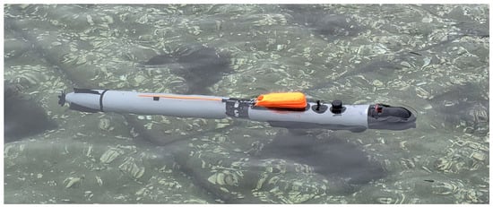
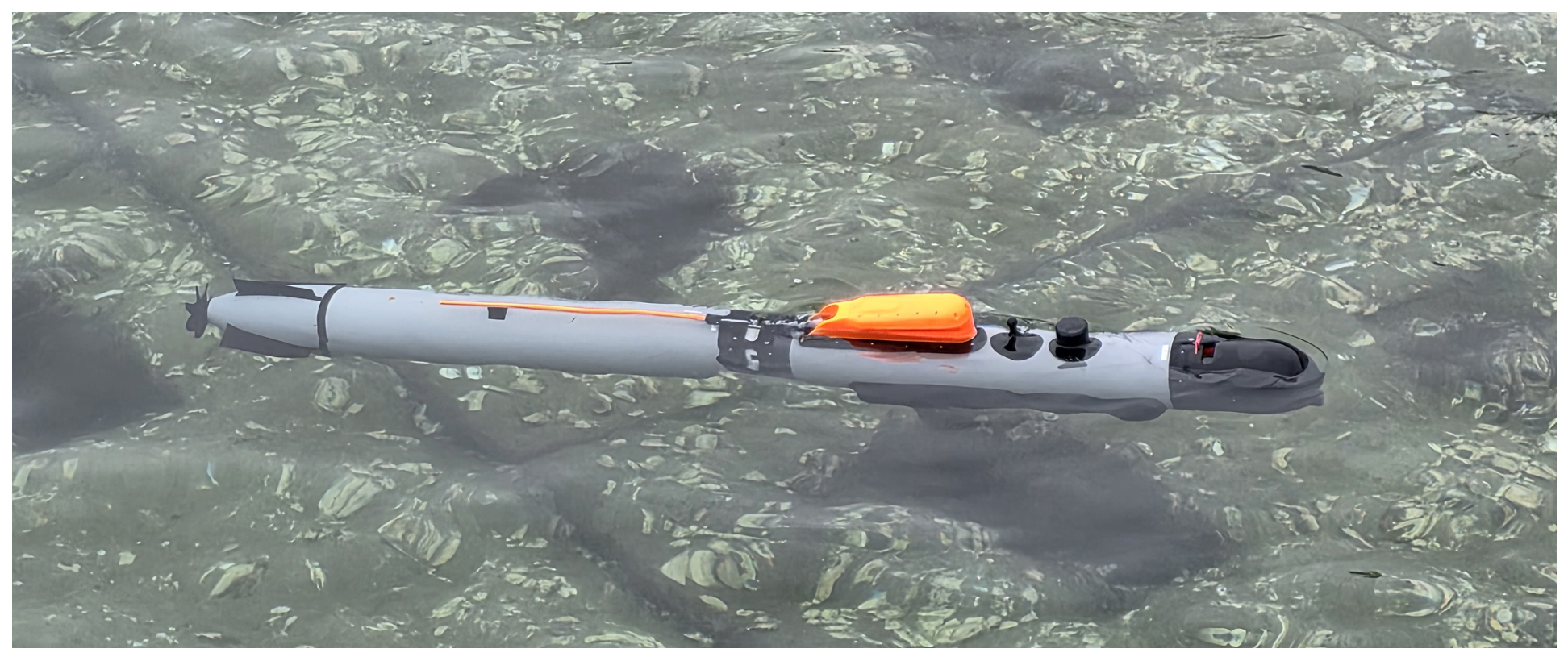
Figure 1 shows the torpedo-type AUV equipped with a TVS used in this study, and its specifications are summarized in Table 1. The AUV was developed for cooperative underwater search missions involving multiple vehicles to locate shipwrecks and drowning victims. These missions require precise maneuvering at low speeds near search targets and within confined spaces. A TVS, whose control authority is relatively less dependent on forward speed, was therefore adopted to improve low-speed maneuverability, enable operation in confined spaces, and minimize external protrusions.
Figure 1.
Torpedo-type AUV equipped with a TVS used in this study.
Table 1.
Specifications of the AUV.
The AUV has a length of and a diameter of . The TVS adjusts the thrust direction by rotating the propulsor itself in the vertical and horizontal directions, generating vertical and horizontal thrust components and the corresponding pitch and yaw control moments. Considering the resultant deflection angle during simultaneous actuation of both axes and the mechanical actuation limits, the maximum vertical and horizontal deflection ranges are ±6 deg and ±7 deg, respectively.
Unlike the gimbaled, ducted thruster used on the Bluefin-9, the present platform adjusts the thrust direction by rotating an open propeller in the vertical and horizontal directions. The manufacturer’s published specifications give a dry mass of approximately for the Bluefin-9, whereas the mass of the present platform is [22].
Underwater vehicle navigation combines information from inertial measurement units (IMUs), Doppler velocity logs (DVLs), depth sensors, and digital compasses (DCSs) to estimate position and motion states [24]. For example, Miller et al. proposed an AUV navigation method that fuses inertial and aiding sensor measurements using an error-state Kalman filter [25]. The navigation system implemented on the present AUV comprises a DVL, an IMU, a depth sensor, a DCS, and a global navigation satellite system (GNSS). GNSS is used for initial alignment of the navigation system at the water surface. During underwater operation, measurements from the DVL, IMU, depth sensor, and DCS are fused using an extended Kalman filter (EKF) to estimate the vehicle’s position, velocity, and attitude. Both navigation estimate updates and trajectory tracking control are performed at intervals of . The sensor configuration and navigation system pre-verification procedure are presented by Lee et al. The reported principal sensor specifications include a GPS position accuracy of –, digital compass accuracies of , , and for roll, pitch, and heading, respectively, and a depth pressure sensor accuracy of of the measurement range. In pre-verification tests using the test equipment along three routes, the final position errors relative to GPS were reported as , , and of the distance traveled, respectively [26]. These values represent sensor specifications and results from separate pre-verification tests; they do not directly establish the navigation estimation accuracy achieved during the present sea-trial control experiments.
2.2. Vehicle Motion and Tracking Error Definitions
This study adopts the coordinate definitions, kinematics, and tracking error definitions presented in the previous study [5]. The error dynamics design and TDE-based control structure are retained, while the control outputs are formulated to match the actuation commands of the TVS-based AUV.
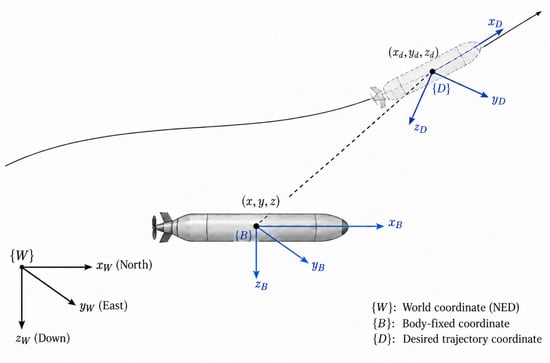
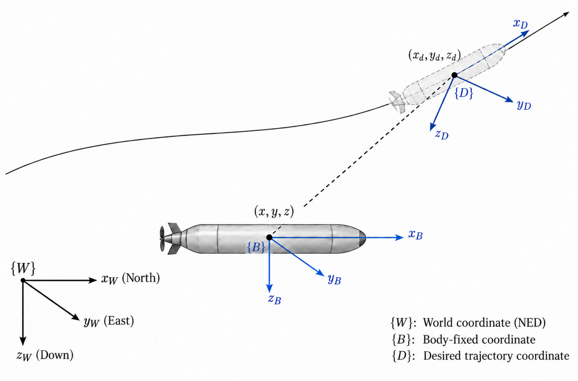
As shown in Figure 2, the world coordinate , body-fixed coordinate , and desired trajectory coordinate are defined to describe the AUV motion and tracking errors. The world coordinate follows the North–East–Down (NED) convention, while the x, y, and z axes of the body-fixed coordinate point forward, starboard, and downward, respectively. The origin of the desired trajectory coordinate is located at the time-varying reference position . With the desired roll set to zero, its orientation is determined by the desired pitch and yaw angles, and , with the -axis aligned with the tangent to the reference trajectory.
Figure 2.
Definition of the world coordinate , body-fixed coordinate , and desired trajectory coordinate .
Consistent with the control model used in the previous study, roll motion is assumed to be negligible, and five-degree-of-freedom motion comprising surge, sway, heave, pitch, and yaw is considered [5]. The AUV kinematics are expressed as follows:
where is the AUV position vector expressed in , and is the translational velocity vector expressed in . The variables u, v, and w denote the surge, sway, and heave velocities, respectively, while and are the pitch and yaw angles. The variables q and r are the pitch and yaw angular velocities expressed in , respectively, and is the rotation matrix from to . The operating range is assumed to satisfy to avoid the singularity in the Euler angle representation.
Following the standard marine vehicle dynamics formulation incorporating rigid-body inertia and added mass, Coriolis and centripetal effects, hydrodynamic damping, and restoring forces and moments, the AUV equations of motion are expressed as follows [6]:
where is the five-degree-of-freedom velocity vector comprising the translational and angular velocities of the AUV. The matrix is the inertia matrix incorporating rigid-body inertia and added mass, is the Coriolis and centripetal matrix, is the hydrodynamic damping matrix, and represents the restoring forces and moments. The vector represents the forces and moments generated by the TVS, and is the disturbance vector. The components , , and are the surge, sway, and heave forces, respectively, while and are the pitch and yaw moments.
The TVS generates forces and moments by adjusting the propulsor thrust and the vertical and horizontal deflection angles. The relationship between the thrust and the moment arising from its point of application is expressed as
where is the thrust vector expressed in , T is the thrust magnitude, and is the unit vector indicating the thrust direction determined by the actual TVS deflection angles. The vector extends from the reference point of the dynamic model to the point of thrust application, and is the moment vector generated by the thrust. Its y- and z-axis components correspond to the pitch moment and yaw moment , respectively. The lateral and vertical forces generated by TVS deflection are coupled with these moments and cannot be assigned independently. Therefore, the AUV remains underactuated. In the implementation, the surge control channel output is converted into a propulsor rotational speed command, while the pitch and yaw control channel outputs are used directly as the vertical and horizontal TVS deflection angle commands, respectively. These implemented control outputs are therefore distinguished from physical forces and moments.
The position tracking error in the world coordinate is defined as
where is the time-varying reference position vector, and is the actual AUV position vector.
The position tracking error in the desired trajectory coordinate is defined as
where is the position tracking error expressed in , and is the rotation matrix from to . The variables and are the desired pitch and yaw angles, respectively.
The time derivative of the position tracking error expressed in the desired trajectory coordinate is given by
where is the time derivative of the position tracking error vector expressed in the desired trajectory coordinate. is the time derivative of the desired rotation matrix, and is the time derivative of the reference position. The first term on the right-hand side accounts for the rotation of the desired trajectory coordinate.
The attitude and controlled velocity tracking errors are defined as
where and are the pitch and yaw tracking errors, respectively, and maps an angular difference to the interval . The variables , , and are the surge velocity, pitch angular velocity, and yaw angular velocity tracking errors, respectively, and , , and are the corresponding desired velocities.
The control objective is to reduce the position tracking error so that the AUV follows a time-varying three-dimensional reference trajectory within its actuation limits. The reference trajectory and the associated desired attitude and velocity signals are specified in the following subsection.
2.3. Reference Trajectories and Operating Conditions
In this study, straight-line and blending segments in the horizontal plane are constructed from the input waypoints to generate time-varying three-dimensional reference signals. Each waypoint specifies a desired horizontal position, depth, and speed. The initial waypoint uses the current horizontal position and speed of the AUV, while the initial depth is set to to represent departure from the water surface.
In the horizontal plane, the incoming and outgoing directions are determined from three consecutive waypoints surrounding an intermediate waypoint. For turning segments, a circular arc with a radius of connects the incoming and outgoing straight-line segments. Consequently, the reference path turns around intermediate waypoints rather than passing directly through them, and the final waypoint is approached along a straight-line segment. Speed transition segments are constructed using the desired waypoint speeds and a specified acceleration of . A separate quintic polynomial is applied to generate the reference depth and its first and second time derivatives. The depth transition duration is determined from the depth difference between consecutive waypoints, the specified speed, and a diving-angle parameter of 5 deg. This parameter determines the depth transition duration rather than directly specifying the desired pitch angle.
The trajectory generation algorithm combines the horizontal straight-line and circular-arc path with the depth transition signal and computes the desired pitch and yaw angles from the direction of reference position increments. The reference signals are updated every , and transitions between segments occur according to their calculated durations, regardless of whether the AUV has reached the corresponding waypoints. The reference signals provided to the controller are summarized in Table 2.
Table 2.
Reference signals provided to the tracking controller.
3. Error-Dynamics-Based Trajectory Tracking Control
This section describes the error-dynamics-based trajectory tracking control method applied to the AUV. The controller retains the error dynamics design and TDE-based estimation and compensation structure proposed in the previous study [5]. First, the desired error dynamics are presented using the position, attitude, and velocity tracking errors. Next, the estimation of nonlinear dynamics and disturbances using TDE and the formulation of the control inputs are described. Finally, the conversion of control outputs into actuator commands and the handling of actuator limits for implementation on the TVS-based AUV are explained.
3.1. Desired Error Dynamics
In this study, the desired error dynamics proposed in the previous study are retained using the tracking errors defined above [5]. This design couples the longitudinal position tracking error with the surge velocity error, and the lateral and vertical position tracking errors with the yaw and pitch angular velocity errors, respectively. In particular, the time derivatives of the position tracking errors are incorporated to reduce position tracking errors caused by steady-state unmatched disturbances.
The desired error dynamics for longitudinal, lateral, and vertical position tracking are formulated as follows:
where , , and are the control gains for the position tracking errors in the respective directions, while , , and are the gains for their time derivatives. and are the gains for the yaw and pitch angular velocity errors, respectively, and all gains are set to positive values. The signs of the vertical position error terms reflect the relationship between pitch motion and vertical motion under the downward-positive coordinate convention.
The above design incorporates the time derivatives of the position errors, distinguishing it from the previous approach that directly couples position errors with velocity and attitude errors. This structure is intended to reduce position tracking errors even when nonzero attitude errors are maintained to compensate for constant disturbances in unactuated directions. The characteristic equations of the desired error dynamics and the analysis of steady-state tracking errors are presented in the previous study; therefore, their derivations are not repeated here [5]. That analysis describes the steady-state behavior of the position tracking errors under conditions including stable error dynamics and steady-state nonlinear terms. These results do not directly guarantee the stability of the entire closed-loop system incorporating TDE estimation errors, TVS actuator command conversion, and actuator limits. In this study, the tracking performance of the controller employing the same desired error dynamics is evaluated through numerical simulations and sea trials.
3.2. Control Law with Time Delay Estimation
This subsection describes the TDE based control law used to realize the desired error dynamics defined above. The surge, pitch, and yaw dynamics are expressed as follows:
where , , and are the surge force, pitch moment, and yaw moment, respectively. , , and are positive nominal inertia coefficients used in the controller design, while , , and represent the remaining dynamic terms after excluding the nominal inertia terms. These terms include the effects of inertia uncertainty, motion coupling, hydrodynamic damping, restoring forces and moments, and disturbances.
Rather than directly calculating , , and , which include the nonlinear terms and disturbances in each channel, using a detailed dynamic model, these terms are estimated using TDE. Under the assumption that the dynamics to be estimated vary little over a sufficiently short time interval, TDE uses control inputs and state derivative information from a previous time instant [19]. Based on the estimation and compensation structure of the previous control design, the estimates for each channel are given by [5]:
where , , and are the estimates of the corresponding dynamic terms, and is a short time delay. In this implementation, information from the previous control cycle is used; therefore, L is set to .
Using these estimates, the control inputs are constructed as follows:
where , , and are auxiliary control inputs used to impose the desired dynamics on the surge velocity and the pitch and yaw angular velocities, respectively. Based on the desired error dynamics defined above, these inputs are constructed as follows:
Here, , , and are the time derivatives of the desired surge velocity and the desired pitch and yaw angular velocities, respectively. The tracking errors and control gains are as defined previously. In the sea-trial implementation, the feedback signals corresponding to the position-error derivatives are calculated using the vehicle velocity and attitude, position errors, and reference trajectory information, rather than by directly applying numerical differentiation to the position errors. Likewise, the auxiliary control inputs are calculated using the relationships in Equation (12), without directly applying numerical differentiation to the velocity and angular velocity errors appearing in Equation (8).
In the ideal case where the TDE estimates match the actual dynamic terms, , , and hold, thereby realizing the desired error dynamics defined above. When TDE estimation errors are present, the following relationships are obtained:
where is the TDE estimation error in each channel. Thus, the actual tracking performance is affected by temporal variations in the estimated dynamics, the accuracy of the state derivatives, and the actuator response to the commands.
The above control structure follows the TDE-based estimation and compensation approach of the previous study [5]. The controller uses the current states and their first time derivatives, the reference signals and their required derivatives, and the previous control inputs. In the above equations, the control inputs are expressed as generalized forces and moments. The correspondence with the propulsor rotational speed and TVS deflection angle commands used in the implementation, the filtering of the TDE estimates, and the handling of actuator limits are described in the next subsection.
3.3. Implementation on the TVS-Based AUV
This subsection describes how the control structure presented above is implemented through actuator commands for the TVS-based AUV. The presented control law uses forces and moments as inputs. In the actual implementation, TDE is formulated directly in command channels using the squared propulsor rotational speed and TVS deflection angles as inputs. Thus, the error dynamics design and TDE-based estimation and compensation structure are retained, while the coefficients of each channel are selected according to the units and response characteristics of the actuator commands. This differs from an approach that first computes physical forces and moments and then converts them into actuator commands using an inverse model.
Figure 3 illustrates the implemented trajectory tracking control architecture.
Figure 3.
Trajectory tracking control architecture for the TVS-based AUV, including TDE filtering, actuator command conversion, and saturation.
The control outputs in the actuator command channels are constructed as follows:
where k is the discrete-time index, and , , and are the auxiliary control inputs defined earlier. The output corresponds to the squared propulsor rotational speed, while and correspond to the vertical and horizontal TVS deflection angles, respectively. The coefficients , , and are associated with the respective command channels, and , , and are the estimation and compensation terms expressed in the units of those channels. These coefficients and estimates are formulated directly in the command channels rather than obtained through simple unit conversions of the physical nominal inertia coefficients and the dynamic estimates , respectively, where .
The TDE estimates use previous inputs that account for actuator limits. In the surge channel, the rotational speed after saturation but before the addition of the dead-zone compensation offset is used. In the pitch and yaw channels, the previous saturated deflection angle commands are used. The estimates for each channel are given by
where is the saturated propulsor rotational speed before dead-zone compensation, and and are the saturated vertical and horizontal TVS deflection angle commands, respectively. denotes the unfiltered TDE estimate.
A first-order recursive filter is applied to reduce abrupt changes in the estimates:
where is the filter coefficient for each channel. The filter coefficients and command-channel coefficients are presented together with the simulation and experimental conditions.
The surge output is converted into a propulsor rotational speed command by taking the square root of its absolute value and applying saturation limits.
Here, is the limited rotational speed before the offset is applied, and is the rotational speed command sent to the propulsor. The parameter is the upper limit of the final command, and is the rotational speed offset for dead-zone compensation. The current implementation uses and . This transformation does not preserve the sign of the surge output: negative outputs are also converted into positive rotational speeds, so no reverse-rotation commands are generated.
The pitch and yaw outputs are used as the vertical and horizontal TVS deflection angle commands, respectively, and are limited according to the mechanical operating range:
where and are the vertical and horizontal TVS deflection angle commands, respectively, and and are the maximum allowable deflection angles in the respective directions. In this implementation, and , and the signs of the commands follow the directional conventions of the actual actuators. Actuator limits are enforced through command saturation, and the saturated previous inputs are used for TDE in the next control cycle.
The lateral and vertical forces generated by TVS deflection are coupled with the pitch and yaw moments. In this implementation, the propulsor rotational speed and the two deflection angles are commanded directly, without a separate control allocation scheme that independently assigns these forces and moments. Thus, TDE estimates and compensates for the coupled dynamics reflected in the response of each control channel; it does not independently specify forces in the unactuated directions. The control algorithm runs every using the navigation state estimates and reference signals. In each cycle, the tracking errors and auxiliary control inputs are calculated, and the TDE estimates are updated using previous inputs and available state derivative information. Estimate filtering, actuator command conversion, and saturation limits are then applied before the final commands are sent to the actuators.
The angular accelerations required by the controller are supplied by the navigation module, which incorporates an EKF and low-pass filtering. Details of the internal processing and filter coefficients are proprietary to the supplier, limiting full reproducibility of the navigation signal preprocessing.
The surge acceleration is calculated by backward differencing the EKF-based surge velocity at the control period of , followed by low-pass filtering to mitigate noise amplification caused by differentiation. The filter output is calculated using weights of 0.8 for the current difference estimate and 0.2 for the previous filter output. If the absolute value of the output exceeds , the previous output is retained. This acceleration signal preprocessing is distinct from the filtering applied to the TDE estimates.
4. Simulation Results
This section compares the performance of two trajectory tracking controllers using a REMUS-based motion model. The previous controller employing coupled error dynamics and TDE [9] is referred to as coupled error dynamics with time delay estimation (CDTDE), while the controller incorporating the time derivatives of the position tracking errors [5] is referred to as error dynamics design with time delay estimation (EDD-TDE). Both controllers are evaluated under identical simulation conditions for each of two multi-waypoint reference trajectories. The control inputs are applied directly to the motion model as surge force and pitch and yaw moments, without conversion into TVS actuator commands. Tracking performance is compared using the RMSE over the full simulation interval and the post-transient interval, together with the control input responses.
The purpose of these simulations is to compare the tracking responses of the two control structures under identical motion model and disturbance conditions. Interactions between the TVS and cross-flow around the stern of the experimental vehicle, as well as changes in hydrodynamic forces due to propulsor deflection, are not explicitly modeled. Therefore, the simulation results should not be interpreted as validation of the hydrodynamic response of the actual TVS platform.
4.1. Simulation Setup and Evaluation Criteria
The numerical simulations use the REMUS-based motion model employed in the previous control study [5]. The foundations of the nonlinear REMUS motion model and the estimation of its hydrodynamic coefficients are presented by Prestero [27]. The simulations are performed in MATLAB R2024b using fourth-order Runge–Kutta integration. The control period is , and the integration step is . The control inputs are applied directly to the motion model as surge force and pitch and yaw moments, without conversion into TVS actuator commands.
The reference trajectories are generated from two sets of horizontal waypoints intended for the sea trials. The same horizontal waypoint layouts are used in the simulations and sea trials, while the desired depths are specified separately according to the conditions of each evaluation environment. The waypoint positions, depths, and desired speeds used in the simulations are listed in Table 3. The desired waypoint speeds are set to for surface maneuvers and for underwater maneuvers. The initial reference speed is set to , and Waypoint 0 denotes the initial reference position. The horizontal coordinates represent relative northward and eastward positions with respect to the starting point of each trajectory, and depth is defined as positive downward.
Table 3.
Waypoint positions, depths, and speeds for the two reference trajectories.
For each trajectory, identical reference signals, initial conditions, and current conditions are applied to CDTDE and EDD-TDE. The initial vehicle position coincides with the starting position of the reference trajectory, and the initial pitch and yaw angles are aligned with the reference attitude. The actual initial translational and angular velocities of the AUV are all set to zero. The controller parameters are listed in Table 4. The control gains were tuned empirically by observing the tracking responses of each controller while accounting for their different error feedback structures. These gains were not obtained by optimizing a predefined common objective function.
Table 4.
Simulation settings and controller parameters.
The current is held constant in the world coordinate, with northward and eastward components of each and a downward component of . The horizontal current magnitude is approximately , directed clockwise from north. The surge force is limited to , while no saturation limits are imposed on the pitch and yaw moments. TDE uses the control inputs and state derivatives from the previous control cycle. Since measurement noise is not considered and the state derivatives are calculated from the model, all TDE estimate filter coefficients are set to 1.
Tracking performance is evaluated using the RMSE of the position errors , , and expressed in the desired trajectory coordinate, together with the surge velocity error and yaw error . The 3D position RMSE, calculated from the magnitude of the position error vector, is also reported to compare the overall position tracking performance. The yaw error is calculated by normalizing the angular difference to the range and is reported in degrees.
The RMSE is calculated separately over the full interval and the post-transient underwater operating interval, with the primary performance comparison focusing on underwater operation. The full evaluation intervals are 0– for Trajectory 1 and 0– for Trajectory 2, while the underwater evaluation intervals are – and –, respectively. Identical evaluation intervals are applied to both controllers for each trajectory, and error variations associated with maneuvers within these intervals are included in the evaluation. The RMSE over the full interval is also reported as a supplementary result that includes the effects of initial responses and operating transitions.
4.2. Comparative Tracking Performance
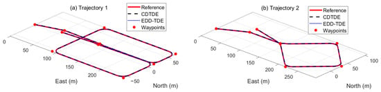
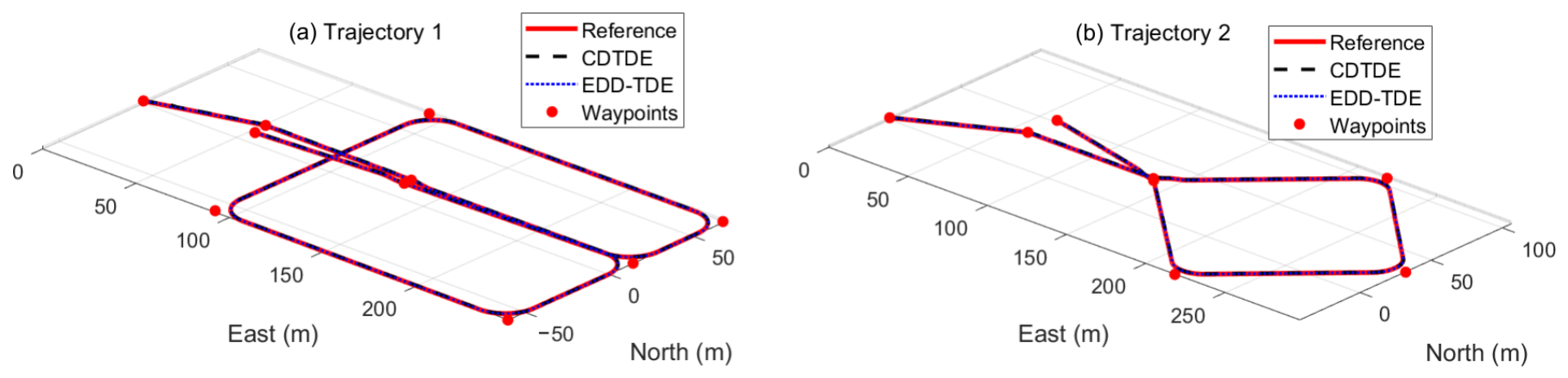
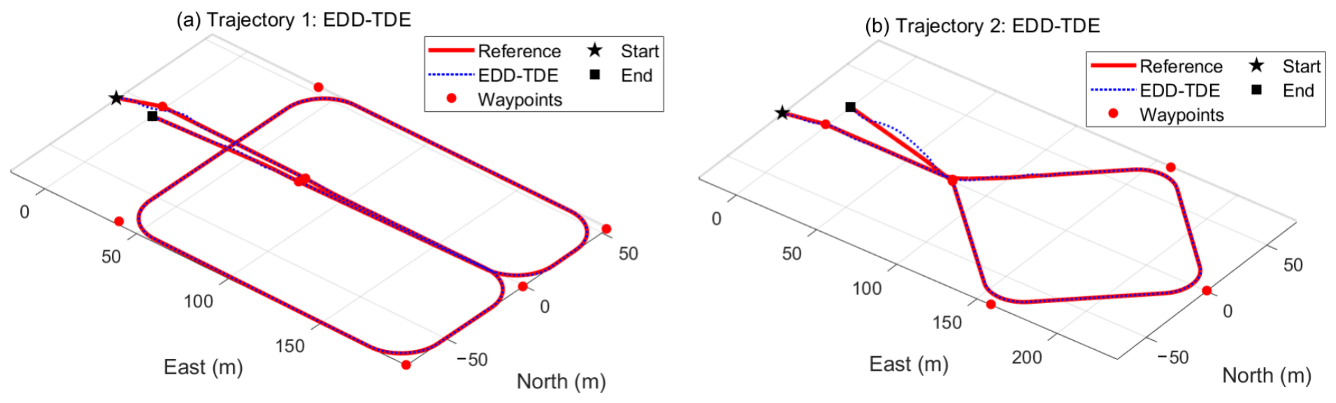
The tracking performance of CDTDE and EDD-TDE is compared for the two reference trajectories. Figure 4 shows the two reference trajectories and the actual trajectories obtained using CDTDE and EDD-TDE in three-dimensional space. For quantitative comparison, Table 5 summarizes the RMSE of the position, surge velocity, and heading errors, together with the 3D position RMSE, over each evaluation interval.
Figure 4.
Reference and actual trajectories obtained using CDTDE and EDD-TDE: (a) Trajectory 1 and (b) Trajectory 2.
Table 5.
Tracking RMSE for the two reference trajectories over the full and post-transient intervals.
EDD-TDE yielded a lower 3D position RMSE than CDTDE for both trajectories. Over the full interval, the RMSE decreased from to for Trajectory 1 and from to for Trajectory 2, corresponding to reductions of approximately 41% and 43%, respectively. Over the post-transient underwater operating interval, the RMSE also decreased from to for Trajectory 1 and from to for Trajectory 2.
EDD-TDE yielded lower position RMSE values in all directions for both trajectories and both evaluation intervals, with particularly pronounced improvements in the lateral and vertical directions. Over the post-transient underwater operating interval, the lateral RMSE decreased from to for Trajectory 1 and from to for Trajectory 2. Over the same interval, the vertical RMSE values were and for CDTDE, compared with and for EDD-TDE, respectively. These results are consistent with the objective of the previous design, which incorporates the time derivatives of the position errors to reduce position tracking errors associated with steady-state nonlinear terms [5]. However, residual lateral errors remained with EDD-TDE, with underwater lateral RMSE values of approximately –.
The surge velocity RMSE decreased slightly with EDD-TDE, while the heading RMSE remained similar for the two controllers. Thus, for the two trajectories and current conditions evaluated, EDD-TDE achieved smaller position tracking errors while maintaining similar surge velocity and heading tracking performance.
The simulations compared the tracking performance of CDTDE and EDD-TDE for two multi-waypoint three-dimensional reference trajectories. The control inputs were applied directly to the motion model as forces and moments. Implementation performance incorporating TVS actuator command conversion and actual actuator responses is evaluated through the sea trials presented in the next section.
5. Experimental Results and Discussion
This section compares the sea trial results of CDTDE and EDD-TDE implemented on the TVS-based AUV. Position, surge velocity, and heading tracking performance is evaluated for two multi-waypoint three-dimensional reference trajectories. The feedback responses of the propulsor rotational speed and TVS deflection angles, together with the characteristics of the recorded actuator commands, are also analyzed. The experimental conditions and evaluation methods are first described, followed by a comparison of the trajectory tracking results and RMSE values for the two controllers. The discussion then examines differences in position tracking performance in each direction between the simulations and sea trials and considers the tracking characteristics observed in the actual implementation, including the residual along-track offset and factors that may contribute to these characteristics.
5.1. Experimental Setup and Evaluation Criteria
The sea trials are conducted using the TVS-based AUV introduced earlier. CDTDE and EDD-TDE are implemented separately on the same platform, and their tracking performance is evaluated for two multi-waypoint three-dimensional reference trajectories. Navigation state estimates are updated and trajectory tracking control is executed at a period of . The output of each controller is converted into propulsor rotational speed and vertical and horizontal TVS deflection angle commands using the method described earlier, with limits imposed according to the actuator operating ranges. The controller parameters used in the experiments are listed in Table 6. Here, , , and are the command-channel coefficients defined in Section 3.3. The control gains, command-channel coefficients, and TDE filter coefficients for both controllers were selected using the same empirical tuning procedure by observing the tracking responses and variations in the estimates. The control gains were set separately to account for the different error feedback structures, while identical command-channel coefficients and TDE filter coefficients were ultimately applied to both controllers. This selection was not based on optimization of a predefined common objective function, and no claim of parameter optimality is made.
Table 6.
Controller parameter settings for the sea trials.
For each trajectory, the two controllers use identical target waypoint layouts, depth settings, and speed settings. For both trajectories, the desired depths are set to during surface operation and during underwater operation, while the desired speeds are set to and , respectively. However, differences in the actual starting positions and initial states lead to differences in the approach trajectories generated from the initial states and the total operating times. Since the trials for the two controllers are conducted separately, environmental conditions such as currents and waves are not assumed to be identical.
Tracking performance is evaluated by comparing the position, surge velocity, and heading estimated by the navigation system with the reference signals. The position errors , , and expressed in the desired trajectory coordinate are used to calculate the directional RMSE values and the 3D position RMSE. The RMSE values of the surge velocity error and heading error are also reported. The heading error is calculated by normalizing the angular difference to the range and is reported in degrees. Therefore, the tracking errors in this study are calculated as the differences between the navigation system estimates and the reference signals. Since independent ground-truth measurements of position, depth, and heading were not obtained during these trials, these metrics characterize tracking performance relative to the navigation estimates and do not constitute an independent validation of absolute tracking accuracy with respect to the actual vehicle states.
The RMSE is calculated separately over the full recorded interval and the post-transient underwater operating interval. The primary quantitative comparison between the two controllers focuses on the constant-depth underwater operating interval following the diving and speed transitions. The RMSE over the full recorded interval is provided as a supplementary metric to characterize the overall recorded responses, including surface maneuvers and diving and surfacing transitions. The underwater evaluation interval begins after the reference trajectory passes the first underwater waypoint and ends before it passes the penultimate waypoint. These margins do not represent theoretical settling times; they were selected empirically by examining the recorded responses to reduce the influence of variations following diving and speed transitions and of responses near the surfacing transition. Waypoint passage times are determined from transitions in the trajectory generator’s waypoint index. The same interval selection rules are applied to both controllers, while the actual evaluation start and end times are determined separately according to the reference trajectory timing in each trial. Over the evaluation intervals of the four selected trials, the reference depth and surge velocity remain constant at and , respectively, and error variations associated with turns are included in the evaluation.
Feedback time histories for the propulsor rotational speed and TVS deflection angles are presented. Separately recorded actuator commands are used to examine how often the prescribed command limits are reached. Directional position tracking performance and residual along-track offsets are also analyzed.
5.2. Comparative Sea-Trial Tracking Performance
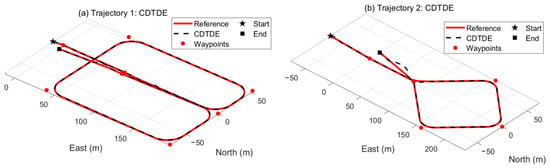
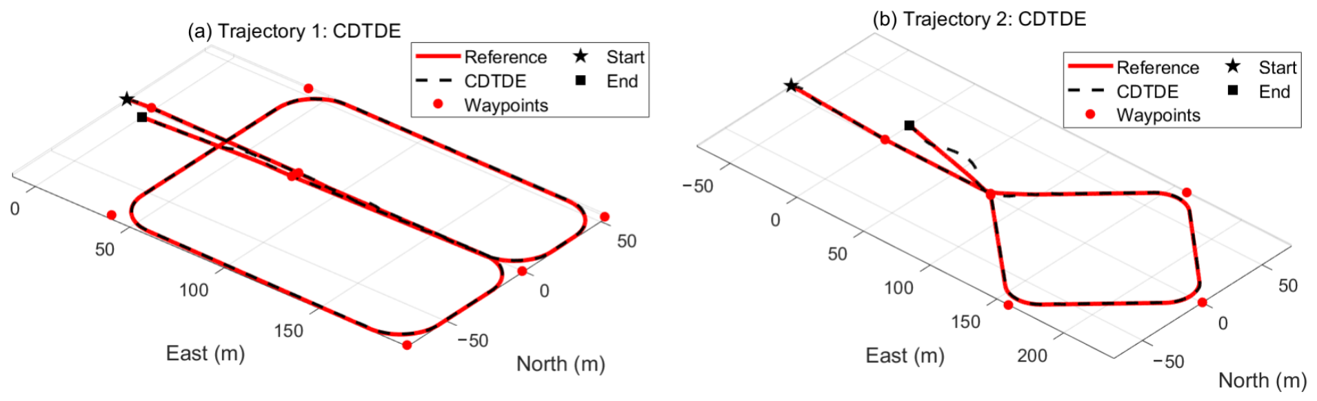
The sea-trial tracking performance of CDTDE and EDD-TDE is compared for the two reference trajectories. Figure 5 and Figure 6 show the reference and actual trajectories obtained using CDTDE and EDD-TDE, respectively, with panels (a) and (b) corresponding to Trajectories 1 and 2. Both controllers tracked paths comprising straight segments and turns, and detailed performance differences are compared using the position errors expressed in the desired trajectory coordinate and their RMSE values.
Figure 5.
Reference and actual trajectories obtained using CDTDE in the sea trials: (a) Trajectory 1 and (b) Trajectory 2.
Figure 6.
Reference and actual trajectories obtained using EDD-TDE in the sea trials: (a) Trajectory 1 and (b) Trajectory 2.
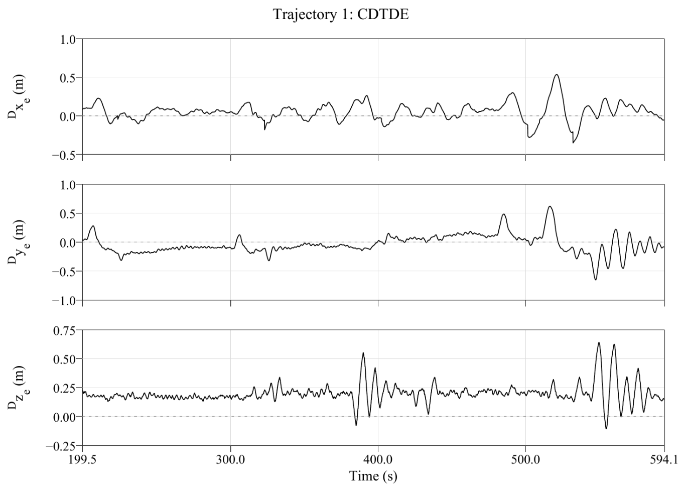
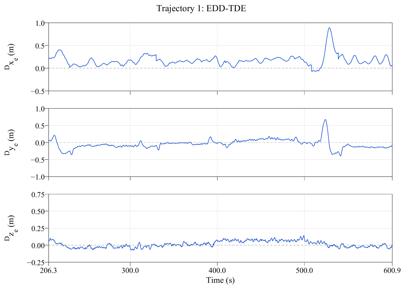
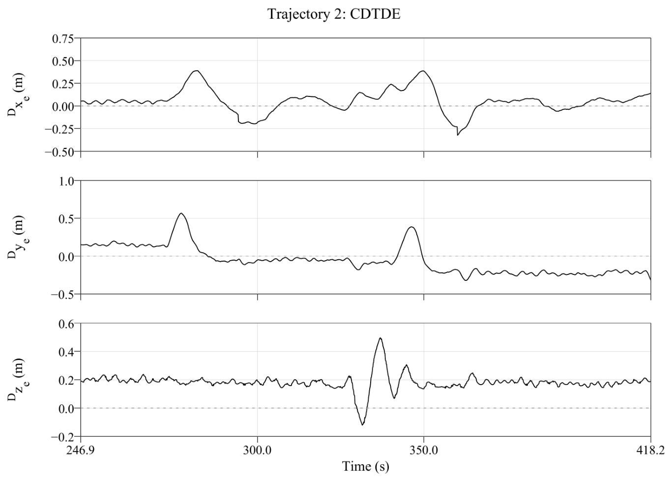
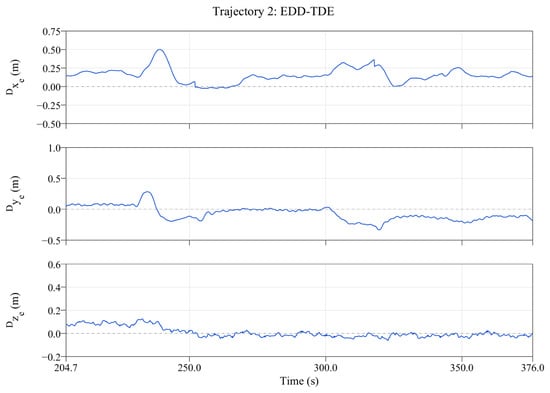
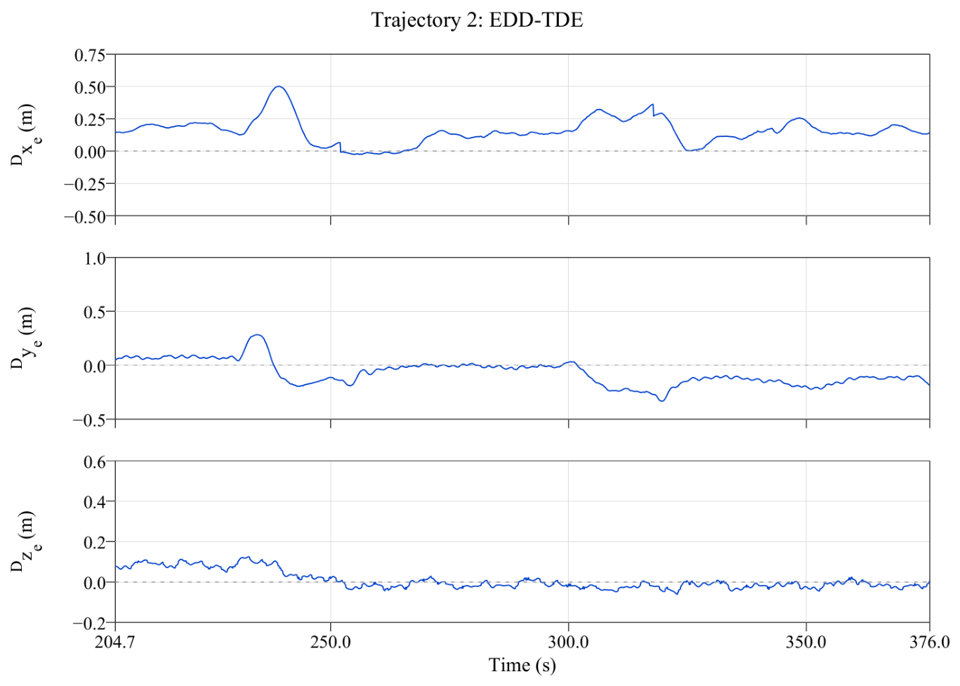
The position error responses for Trajectory 1 are presented in Figure 7 and Figure 8, while those for Trajectory 2 are presented in Figure 9 and Figure 10. Each figure shows the along-track, lateral, and vertical position errors expressed in the desired trajectory coordinate frame over the post-transient underwater evaluation interval. For Trajectory 1, these intervals are – for CDTDE and – for EDD-TDE. For Trajectory 2, the corresponding intervals are – and –, respectively. The position, surge velocity, and heading error plots retain the recorded time axis of each trial, and identical vertical-axis limits are applied to corresponding error components for both controllers within each trajectory.
Figure 7.
Position tracking errors expressed in the desired trajectory coordinate frame for Trajectory 1 using CDTDE over the post-transient underwater evaluation interval.
Figure 8.
Position tracking errors expressed in the desired trajectory coordinate frame for Trajectory 1 using EDD-TDE over the post-transient underwater evaluation interval.
Figure 9.
Position tracking errors expressed in the desired trajectory coordinate frame for Trajectory 2 using CDTDE over the post-transient underwater evaluation interval.
Figure 10.
Position tracking errors expressed in the desired trajectory coordinate frame for Trajectory 2 using EDD-TDE over the post-transient underwater evaluation interval.
Different residual errors were observed in each direction during the underwater evaluation interval. A persistent positive vertical error was observed with CDTDE, whereas the vertical offset was substantially reduced with EDD-TDE. However, a positive along-track offset remained with EDD-TDE, indicating that the vehicle lagged behind the reference trajectory. Thus, the improvement in position tracking performance achieved by EDD-TDE was not uniform across all directions, and the directional error characteristics are evaluated together with the overall position RMSE.
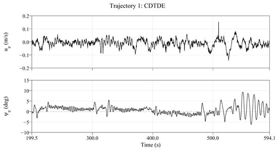
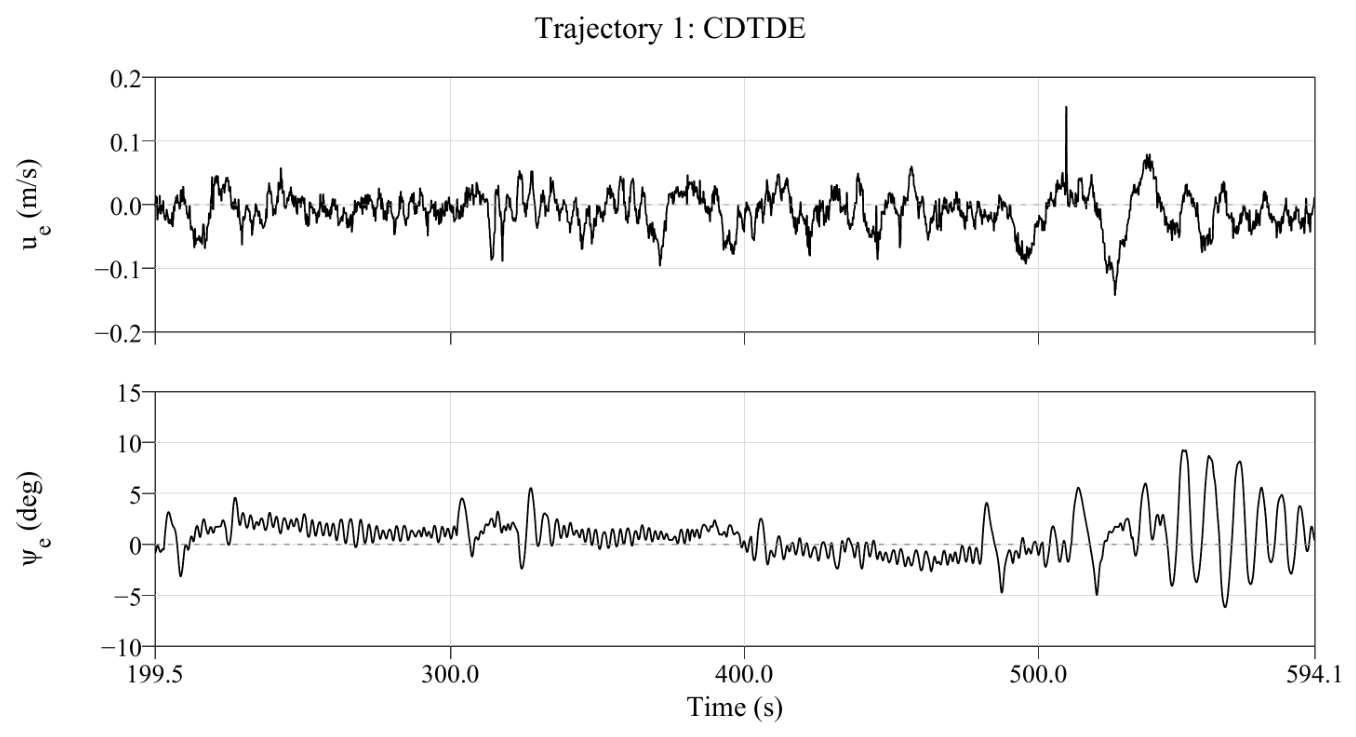
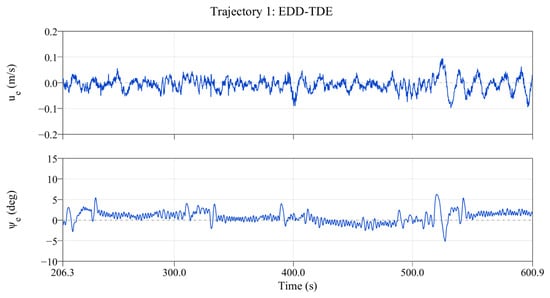
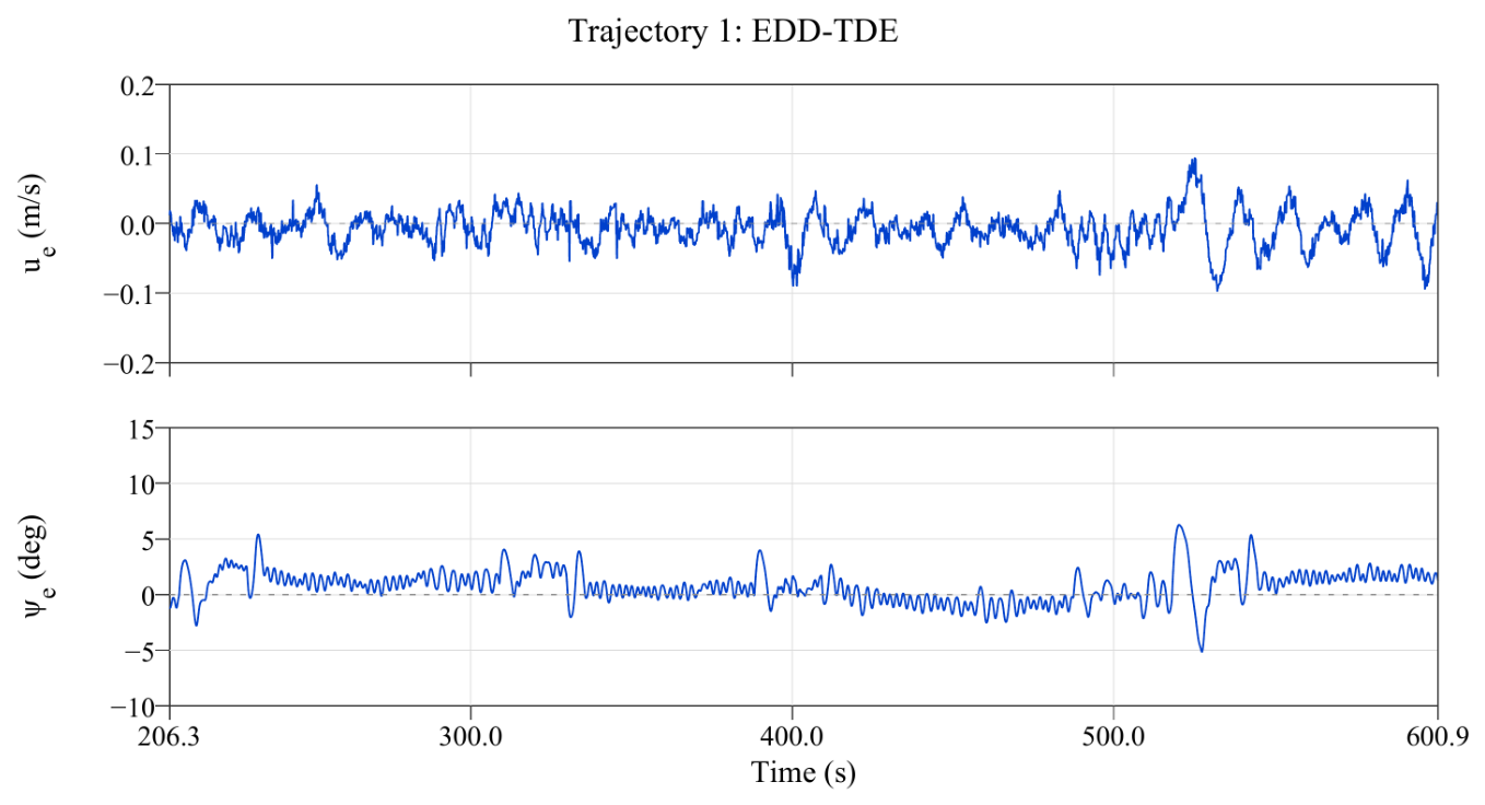
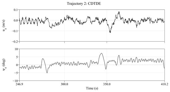
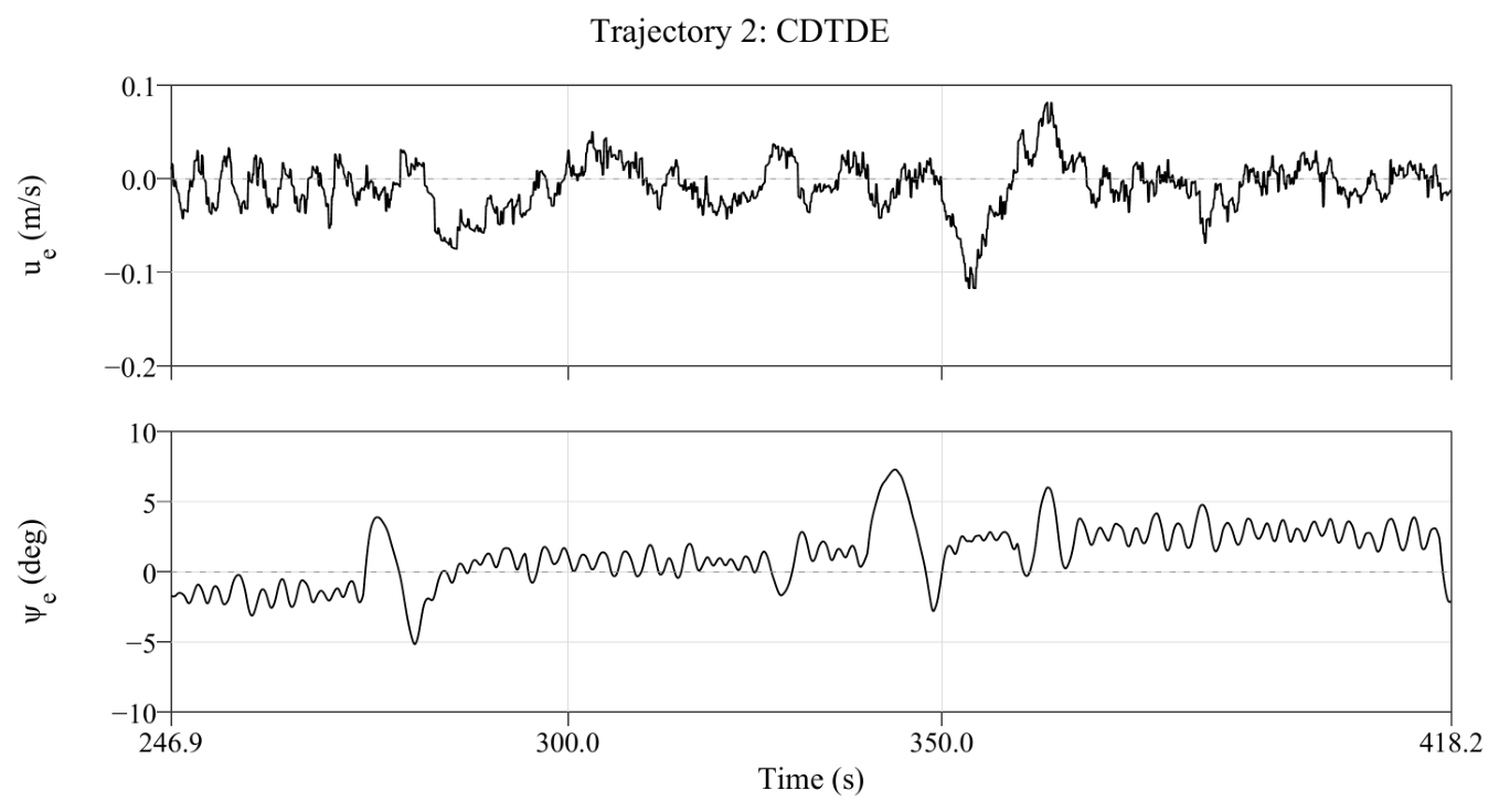
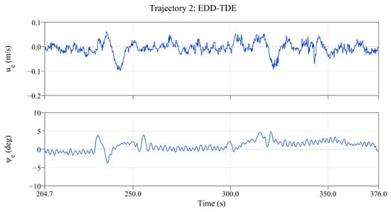
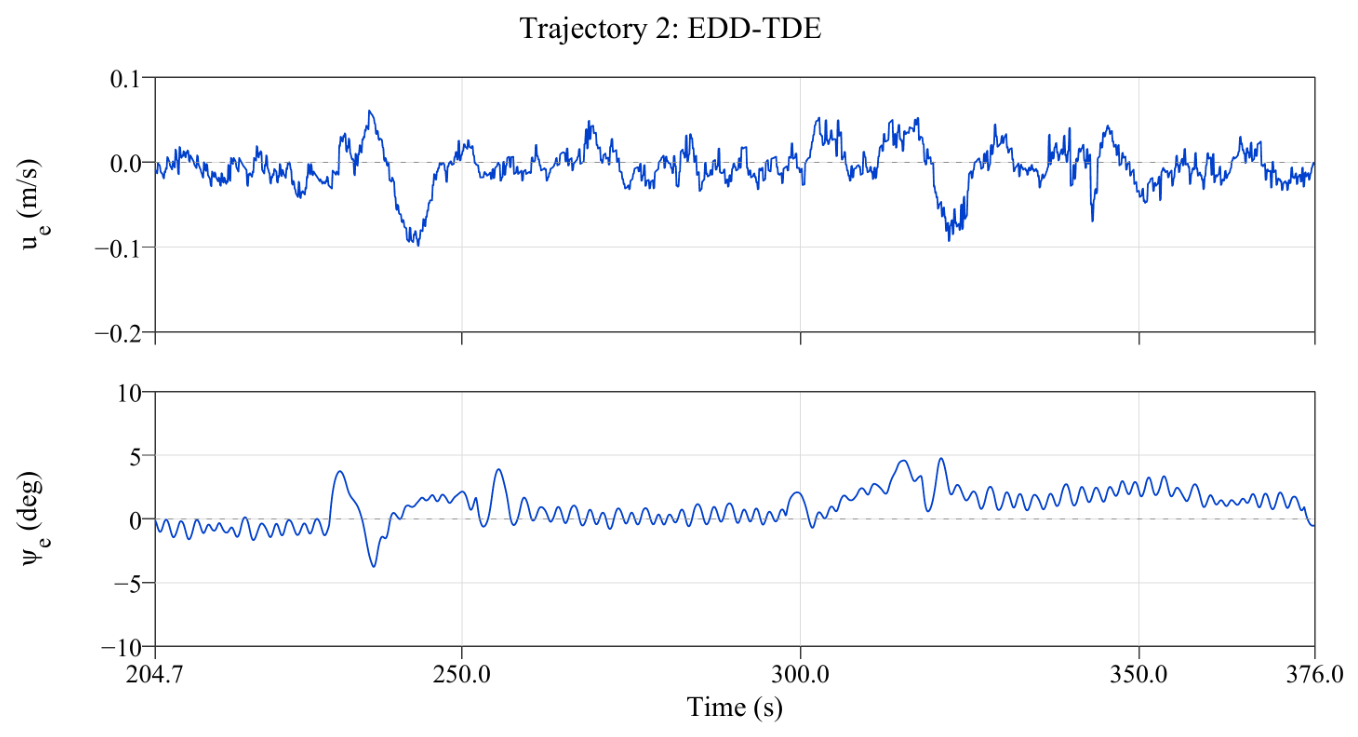
The surge velocity and heading error responses for Trajectory 1 are presented in Figure 11 and Figure 12, while those for Trajectory 2 are presented in Figure 13 and Figure 14. Each figure shows the responses over the underwater evaluation intervals specified above. The surge velocity error generally fluctuated around zero, while small residual offsets and temporal variations were observed in the heading error. Error variations within these intervals, including those occurring during turns, are included in the RMSE evaluation.
Figure 11.
Surge velocity and heading tracking errors for Trajectory 1 using CDTDE over the post-transient underwater evaluation interval.
Figure 12.
Surge velocity and heading tracking errors for Trajectory 1 using EDD-TDE over the post-transient underwater evaluation interval.
Figure 13.
Surge velocity and heading tracking errors for Trajectory 2 using CDTDE over the post-transient underwater evaluation interval.
Figure 14.
Surge velocity and heading tracking errors for Trajectory 2 using EDD-TDE over the post-transient underwater evaluation interval.
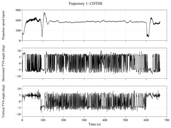
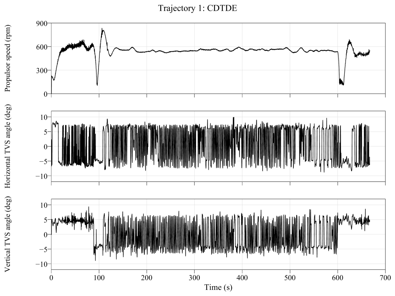
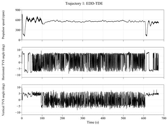
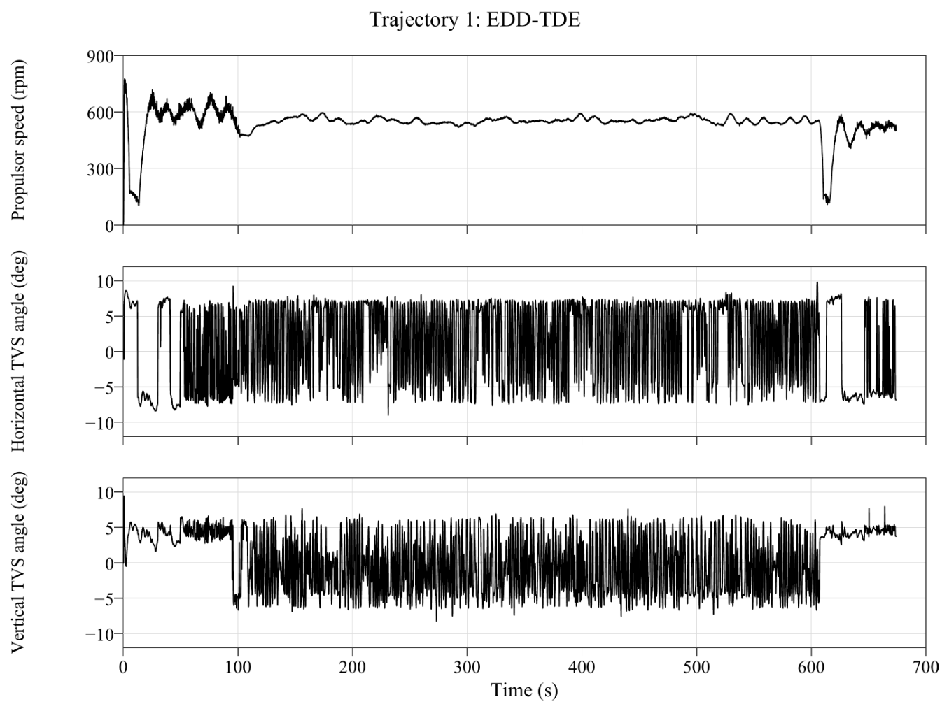
Figure 15 and Figure 16 present representative actuator feedback responses for Trajectory 1 using CDTDE and EDD-TDE, respectively, including the propulsor rotational speed and TVS deflection angles. Both figures show feedback values received from the actuation system over the full recorded intervals, with identical vertical-axis limits applied to corresponding panels. The propulsor rotational speed exhibited large changes around the diving and surfacing transitions, while fluctuating within a relatively consistent range during underwater operation. Rapid changes were observed in the horizontal and vertical TVS deflection angle feedback.
Figure 15.
Actuator feedback responses for Trajectory 1 using CDTDE. From top to bottom: propulsor rotational speed, horizontal TVS deflection angle, and vertical TVS deflection angle.
Figure 16.
Actuator feedback responses for Trajectory 1 using EDD-TDE. From top to bottom: propulsor rotational speed, horizontal TVS deflection angle, and vertical TVS deflection angle.
The degree of controller command saturation was evaluated over each underwater evaluation interval using command values recorded separately from the feedback. The horizontal and vertical deflection angle command limits were and , respectively. The proportion of evaluation samples in which the absolute command value reached the corresponding limit was calculated. To account for numerical rounding, samples within of the limit were included. For Trajectory 1, the horizontal command limit was reached in and of the samples for CDTDE and EDD-TDE, respectively, while the corresponding proportions for the vertical command were and . For Trajectory 2, the horizontal proportions were and , and the vertical proportions were and , respectively. Although these proportions decreased with EDD-TDE, both controllers exhibited repeated command saturation during underwater operation. These proportions characterize saturation imposed on the controller output commands and do not directly measure mechanical saturation or actuator loading.
To quantitatively compare tracking performance during underwater operation, Table 7 summarizes the RMSE values over the underwater operating intervals, with the full-record RMSE values also provided as supplementary results. Over the underwater operating interval, the 3D position RMSE decreased from for CDTDE to for EDD-TDE in Trajectory 1 and from to in Trajectory 2. These correspond to reductions of approximately 13.7% and 23.4%, respectively.
Table 7.
Tracking RMSE for the two reference trajectories in the sea trials over the full recorded intervals and the post-transient underwater operating intervals.
Comparing the directional position RMSE values over the underwater operating interval, the lateral RMSE decreased from to for Trajectory 1 and from to for Trajectory 2. The vertical RMSE decreased from to and from to , corresponding to reductions of approximately 78.2% and 76.3%, respectively. In contrast, the along-track RMSE increased from to for Trajectory 1 and from to for Trajectory 2. Thus, the reduction in the 3D position RMSE achieved by EDD-TDE over the underwater operating interval resulted from reductions in the lateral and vertical errors outweighing the increase in the along-track error.
Over the underwater operating interval, the surge velocity RMSE decreased from to for Trajectory 1 and from to for Trajectory 2. The heading RMSE also decreased from to and from to , respectively. For the underwater operating intervals of the selected trials for both trajectories, EDD-TDE yielded lower RMSE values for all evaluated metrics except the along-track position error.
The RMSE over the full recorded interval includes transient responses during surface maneuvers and diving and surfacing transitions and may also be affected by differences in the initial positions and states between trials. Therefore, the quantitative comparison of the two controllers focuses on underwater operating intervals selected using the same criteria.
To assess sensitivity to the evaluation interval selection, the RMSE values were recalculated for nine combinations of start margins of 10, 20, and and end margins of 0, 5, and . Across all combinations, EDD-TDE yielded lower lateral and vertical position RMSE values, surge velocity RMSE, and heading RMSE than CDTDE, but higher along-track position RMSE. The reductions in 3D position RMSE ranged from approximately – for Trajectory 1 and – for Trajectory 2, indicating that the main comparative performance trends were maintained within the examined range of time margins.
5.3. Discussion of Simulation and Experimental Results
The simulations and sea trials showed a common trend in which EDD-TDE yielded lower lateral and vertical position RMSE values than CDTDE. In particular, the persistent vertical offset observed with CDTDE during underwater operation was substantially reduced with EDD-TDE. These results are consistent with the objective of the previous control design, which incorporates the time derivatives of the position errors to reduce position tracking errors associated with steady-state nonlinear terms [5]. Although the along-track RMSE increased in the sea trials, reductions in the lateral and vertical errors outweighed this increase, resulting in a lower 3D position RMSE over the underwater operating interval for both trajectories.
In contrast, along-track tracking performance exhibited different trends in the simulations and sea trials. EDD-TDE yielded a lower along-track RMSE than CDTDE in the simulations but a higher value in the sea trials. A positive along-track offset remained during underwater operation, indicating that the vehicle lagged behind the reference trajectory. Thus, the improvement in position tracking performance observed in the sea trials was not uniform across all directions; rather, improvements in the lateral and vertical directions contributed to better overall position tracking performance.
These differences may be related to differences between the simulations and the actual implementation. The simulations used state derivatives calculated from the model without measurement noise and applied the control inputs directly to the motion model as forces and moments. Furthermore, the simulations did not explicitly model the stern flow associated with TVS deflection or the hydrodynamic interactions between the propulsor and the hull. These effects may contribute to differences between the simulated responses and those of the actual platform. In contrast, the sea trials used navigation estimates and implemented the control outputs as propulsor rotational speed and TVS deflection angle commands. Therefore, the accuracy and consistency of navigation estimates should be considered when interpreting tracking performance [7]. Actual thruster dynamics may also affect the response to actuator commands [8]. In addition, the coupling between the forces and moments generated by the TVS may affect the tracking response. In particular, EDD-TDE uses the time derivatives of the position errors as feedback, so biases in these signals and the relative magnitudes of the position and derivative feedback gains may contribute to the residual along-track error. However, the effects of these factors were not isolated, and comparative trials with different gain settings were not conducted. Therefore, the cause of the along-track offset cannot be conclusively identified from the present trials. Furthermore, this comparison reflects the performance differences observed with empirically selected parameter settings and does not isolate the effects of the control structure from those of the gain settings.
Both controllers exhibited relatively large transient responses during the initial approach and around the diving and surfacing transitions. During surface maneuvers, thrust variations caused by insufficient propulsor submergence may have contributed to these responses, while differences in the initial positions and states between trials may also have affected the RMSE over the full recorded interval. Moreover, because the trials for the two controllers were conducted separately, identical environmental conditions cannot be assumed. Accordingly, the sea-trial performance comparison focuses on underwater operating intervals selected using the same rules, while the simulation and sea-trial results are interpreted primarily in terms of directional performance trends rather than absolute RMSE values.
In Table 7, the vertical RMSE of EDD-TDE over the underwater operating intervals was approximately –. This value represents the residual tracking error calculated from the difference between the navigation-estimated and reference positions, expressed in the desired trajectory coordinate frame; it does not establish absolute depth accuracy at the same level. Navigation estimation errors and filtering characteristics may affect the calculated RMSE, and using the same navigation system for both controllers does not guarantee identical navigation errors across separately conducted trials. Therefore, the observed reduction in vertical error is interpreted as an improvement in tracking performance relative to the navigation estimates. Independent reference measurements are required to validate absolute position and depth tracking accuracy.
Rapid changes and repeated saturation of the TVS deflection angle commands were identified as limitations of the present implementation. To examine the consistency of the parameter settings and command calculations, the auxiliary control inputs and command generation process were reconstructed using the recorded states, tracking errors, control gains, and TDE-related variables. Over the underwater evaluation intervals of the four analyzed trials, the reconstructed TVS commands agreed with the recorded commands to within a maximum difference of approximately . No inconsistencies between the recorded parameters and the command calculations were found within the scope of this verification. However, this confirms only the consistency of the command calculations; it does not establish that the selected gains are appropriate for the actuator dynamics and operating constraints.
Repeated command changes and saturation may increase actuator loading and wear. Although command magnitudes were limited in the present implementation, the actual actuator dynamics and allowable command rates were not explicitly considered, and actuator loading, fatigue, and service life were not evaluated in these trials. Therefore, improved tracking performance alone does not establish suitability for long-term operation. Future work will develop a model incorporating propulsor and TVS dynamics and the coupling between forces and moments, and jointly examine allowable command rates, gain settings, and filter settings to reduce command fluctuations and saturation and improve tracking performance under actual operating conditions.
6. Conclusions
In this study, a trajectory tracking controller proposed in previous work was implemented on a TVS-based torpedo-type AUV while retaining its error dynamics design and TDE-based estimation and compensation structure. In the implementation, the control outputs were formulated as propulsor rotational speed and TVS deflection angle commands, with estimation filtering and actuator command limits applied. Numerical simulations and sea trials were conducted for two multi-waypoint three-dimensional reference trajectories to compare the tracking performance of CDTDE and EDD-TDE.
In the simulations using a REMUS-based motion model, EDD-TDE yielded lower directional position RMSE values and a lower 3D position RMSE than CDTDE for both trajectories. During the post-transient underwater operating intervals of the sea trials, the lateral and vertical position RMSE values also decreased, with reductions in the 3D position RMSE of approximately 13.7% and 23.4% for Trajectories 1 and 2, respectively. In particular, the vertical RMSE decreased by approximately 78.2% and 76.3%, substantially reducing the persistent vertical offset observed with CDTDE. The surge velocity and heading RMSE values also decreased over these intervals. In contrast, the along-track position RMSE increased, and a positive position offset relative to the reference trajectory remained.
These results demonstrate that applying EDD-TDE to a TVS-based AUV can improve overall position tracking performance during underwater operation. However, the residual along-track offset, transient responses during the initial approach and diving and surfacing transitions, and repeated saturation and rapid changes in TVS commands were identified as aspects requiring further improvement. Future work will develop a model incorporating propulsor and TVS dynamics and the coupling between forces and moments, and jointly examine allowable actuator rates, derivative signal consistency, and control gain settings to improve tracking performance and the suitability of actuator commands.
Author Contributions
Conceptualization, H.K. and G.R.C.; methodology, H.K., J.-H.L. and S.J. (Sangrok Jin); software, H.K.; hardware implementation and testing, H.K., S.J. (Seongho Jin), S.K., M.-G.K., K.K., M.H.Y. and G.L.; validation and formal analysis, H.K., J.-H.L. and G.R.C.; investigation, H.K., J.-H.L. and G.R.C.; data curation, H.K. and S.J. (Seongho Jin); writing—original draft preparation, H.K.; writing—review and editing, H.K. and S.J. (Sangrok Jin); visualization, H.K. and S.J. (Sangrok Jin); supervision, H.K. and S.J. (Sangrok Jin); project administration, H.K. All authors have read and agreed to the published version of the manuscript.
Funding
This research was supported by the Korea Institute of Marine Science & Technology Promotion (KIMST), funded by the Ministry of Oceans and Fisheries, Republic of Korea (grant number RS-2023-00256122).
Data Availability Statement
The raw data supporting the conclusions of this article will be made available by the authors upon reasonable request.
Acknowledgments
ChatGPT (OpenAI, GPT-6) was used solely for language editing, grammatical correction, and improving the clarity and readability of the manuscript. The authors reviewed and revised all AI-assisted outputs and take full responsibility for the content of the manuscript.
Conflicts of Interest
The authors Kyosuk Kim, Myeong Ho Yang and Gyeongmok Lee are employed by the company Hanwha Systems. The remaining authors declare that the research was conducted in the absence of any commercial or financial relationships that could be construed as potential conflicts of interest.
References
- Wynn, R.B.; Huvenne, V.A.; Le Bas, T.P.; Murton, B.J.; Connelly, D.P.; Bett, B.J.; Ruhl, H.A.; Morris, K.J.; Peakall, J.; Parsons, D.R.; et al. Autonomous Underwater Vehicles (AUVs): Their past, present and future contributions to the advancement of marine geoscience. Mar. Geol. 2014, 352, 451–468. [Google Scholar] [CrossRef] [Scilit]
- Yuh, J. Design and Control of Autonomous Underwater Robots: A Survey. Auton. Robot. 2000, 8, 7–24. [Google Scholar] [CrossRef] [Scilit]
- Evans, J.; Nahon, M. Dynamics modeling and performance evaluation of an autonomous underwater vehicle. Ocean Eng. 2004, 31, 1835–1858. [Google Scholar] [CrossRef] [Scilit]
- Aguiar, A.P.; Hespanha, J.P. Trajectory-Tracking and Path-Following of Underactuated Autonomous Vehicles with Parametric Modeling Uncertainty. IEEE Trans. Autom. Control 2007, 52, 1362–1379. [Google Scholar] [CrossRef] [Scilit]
- Cho, G.R.; Kang, H.; Kim, M.G.; Lee, M.J.; Li, J.H. Trajectory tracking of torpedo-like auvs using error dynamics design. In Proceedings of the OCEANS 2023-Limerick; IEEE: Piscataway, NJ, USA, 2023; pp. 1–7. [Google Scholar]
- Fossen, T.I. Handbook of Marine Craft Hydrodynamics and Motion Control, 2nd ed.; John Wiley & Sons: Hoboken, NJ, USA, 2021. [Google Scholar] [CrossRef] [Scilit]
- Paull, L.; Saeedi, S.; Seto, M.; Li, H. AUV Navigation and Localization: A Review. IEEE J. Ocean. Eng. 2014, 39, 131–149. [Google Scholar] [CrossRef] [Scilit]
- Yoerger, D.R.; Cooke, J.G.; Slotine, J.J.E. The influence of thruster dynamics on underwater vehicle behavior and their incorporation into control system design. IEEE J. Ocean. Eng. 1990, 15, 167–178. [Google Scholar] [CrossRef] [Scilit]
- Cho, G.R.; Kang, H.; Kim, M.G.; Lee, M.J.; Li, J.H.; Kim, H.; Lee, H.; Lee, G. An experimental study on trajectory tracking control of torpedo-like auvs using coupled error dynamics. J. Mar. Sci. Eng. 2023, 11, 1334. [Google Scholar] [CrossRef] [Scilit]
- Eng, Y.H.; Chitre, M.; Ng, K.M.; Teo, K.M. Minimum speed seeking control for nonhovering autonomous underwater vehicles. J. Field Robot. 2016, 33, 706–733. [Google Scholar] [CrossRef] [Scilit]
- Xiang, X.; Yu, C.; Zhang, Q.; Wilson, P.A.; Xu, G. Manoeuvring-based actuation evaluation of an AUV with control surfaces and through-body thrusters. Appl. Ocean Res. 2020, 96, 102046. [Google Scholar] [CrossRef] [Scilit]
- Maki, A.; Tsutsumoto, T.; Miyauchi, Y. Fundamental research on the maneuverability of the underwater vehicle having thrust vectoring system. J. Mar. Sci. Technol. 2018, 23, 495–506. [Google Scholar] [CrossRef] [Scilit]
- Liu, T.; Hu, Y.; Xu, H.; Zhang, Z.; Li, H. Investigation of the vectored thruster AUVs based on 3SPS-S parallel manipulator. Appl. Ocean Res. 2019, 85, 151–161. [Google Scholar] [CrossRef] [Scilit]
- Lapierre, L.; Jouvencel, B. Robust Nonlinear Path-Following Control of an AUV. IEEE J. Ocean. Eng. 2008, 33, 89–102. [Google Scholar] [CrossRef] [Scilit]
- Paliotta, C.; Lefeber, E.; Pettersen, K.Y.; Pinto, J.; Costa, M.; de Sousa, J.B. Trajectory Tracking and Path Following for Underactuated Marine Vehicles. IEEE Trans. Control Syst. Technol. 2019, 27, 1423–1437. [Google Scholar] [CrossRef] [Scilit]
- Elmokadem, T.; Zribi, M.; Youcef-Toumi, K. Terminal sliding mode control for the trajectory tracking of underactuated autonomous underwater vehicles. Ocean Eng. 2017, 129, 613–625. [Google Scholar] [CrossRef] [Scilit]
- Zhang, J.; Xiang, X.; Zhang, Q.; Li, W. Neural network-based adaptive trajectory tracking control of underactuated AUVs with unknown asymmetrical actuator saturation and unknown dynamics. Ocean Eng. 2020, 218, 108193. [Google Scholar] [CrossRef] [Scilit]
- Guo, L.; Zhou, R.; Wang, Z.; Guo, Q.; Ma, L.; Hu, C.; Luo, J. Three-dimensional trajectory tracking of autonomous underwater vehicles via neural network learning finite time adaptive robust control. Ocean Eng. 2025, 341, 122454. [Google Scholar] [CrossRef] [Scilit]
- Youcef-Toumi, K.; Ito, O. A Time Delay Controller for Systems with Unknown Dynamics. J. Dyn. Syst. Meas. Control 1990, 112, 133–142. [Google Scholar] [CrossRef] [Scilit]
- Yu, C.; Liu, C.; Xiang, X.; Zeng, Z.; Wei, Z.; Lian, L. Line-of-sight guided time delay control for three-dimensional coupled path following of underactuated underwater vehicles with roll dynamics. Ocean Eng. 2020, 207, 107410. [Google Scholar] [CrossRef] [Scilit]
- Cho, G.R.; Li, J.H.; Park, D.; Jung, J.H. Robust trajectory tracking of autonomous underwater vehicles using back-stepping control and time delay estimation. Ocean Eng. 2020, 201, 107131. [Google Scholar] [CrossRef] [Scilit]
- General Dynamics Mission Systems. Bluefin-9 Unmanned Underwater Vehicle: Product Datasheet. 2025. Available online: https://gdmissionsystems.com/-/media/general-dynamics/maritime-and-strategic-systems/bluefin/pdf/bluefin-9-auv-datasheet.ashx (accessed on 26 October 2026).
- Xia, H.; Wang, P.; Jin, Z.; An, X.; Ding, Y. Maneuverability analysis of thrust vectoring ducted propeller with deflector. Ocean Eng. 2020, 213, 107614. [Google Scholar] [CrossRef] [Scilit]
- Kinsey, J.C.; Eustice, R.M.; Whitcomb, L.L. A Survey of Underwater Vehicle Navigation: Recent Advances and New Challenges. In Proceedings of the IFAC Conference of Manoeuvring and Control of Marine Craft, Lisbon, Portugal, 20–22 September 2006; pp. 1–12. [Google Scholar]
- Miller, P.A.; Farrell, J.A.; Zhao, Y.; Djapic, V. Autonomous Underwater Vehicle Navigation. IEEE J. Ocean. Eng. 2010, 35, 663–678. [Google Scholar] [CrossRef] [Scilit]
- Lee, H.; Lee, G.; Kim, H.S.; Choi, K.; Choo, J.; Kang, H. Development of Test-Equipment for AUVs’ Navigation Performance Pre-verification. J. Korea Robot. Soc. 2023, 18, 472–480. [Google Scholar] [CrossRef] [Scilit]
- Prestero, T. Verification of a Six-Degree of Freedom Simulation Model for the REMUS Autonomous Underwater Vehicle. Master’s Thesis, Massachusetts Institute of Technology and Woods Hole Oceanographic Institution, Cambridge, MA, USA, 2001. [Google Scholar] [CrossRef] [Scilit]



Disclaimer/Publisher’s Note: The statements, opinions and data contained in all publications are solely those of the individual author(s) and contributor(s) and not of MDPI and/or the editor(s). MDPI and/or the editor(s) disclaim responsibility for any injury to people or property resulting from any ideas, methods, instructions or products referred to in the content. |
© 2026 by the authors. Licensee MDPI, Basel, Switzerland. This article is an open access article distributed under the terms and conditions of the Creative Commons Attribution (CC BY) license.