


Abstract
Ammonia is regarded as a promising carbon-free fuel for the green and low-carbon transition of the shipping industry, yet its high ignition energy requirement and slow flame propagation make high ammonia substitution ratios (AER) challenging for ammonia/diesel dual-fuel marine engines. This study numerically investigates the combustion and emission characteristics of a marine ammonia-diesel dual-fuel engine under high AER. A computational model of the MAN L23/30H four-stroke marine engine was developed in CONVERGE, coupling the RANS equations with the RNG k-ε turbulence model, the KH-RT spray breakup model, and the SAGE detailed-chemistry combustion solver, and was validated against experimental in-cylinder pressure data. Combustion and emission behaviors under AER of 50–90% at 100% and 50% loads, together with the effects of the ammonia premixed equivalence ratio at the 90% substitution level, were systematically analyzed. The results show that dual-fuel combustion proceeds through diesel pilot auto-ignition followed by ammonia flame propagation, and that increasing AER extends the ignition delay and first elevates and then reduces peak cylinder pressure. At 100% load, raising AER from 50% to 70% improves both combustion efficiency and indicated thermal efficiency, whereas at 90% AER and especially at 50% load, the drastically reduced pilot diesel quantity severely deteriorates combustion. An optimal ammonia premixed equivalence ratio of approximately 0.5 was identified for thermal efficiency, beyond which combustion phasing is markedly delayed and misfire eventually occurs. Emissions analysis reveals non-monotonic NO and NO2 formation governed by the reduction effects of ammonia-derived radicals, higher N2O formation under low-temperature, low-load conditions, and substantially increased NOx and unburned NH3 emissions at 90% AER. The novelty of this work lies in systematically quantifying the combustion and emission behavior of a marine ammonia/diesel dual-fuel engine over a wide high-AER range (50–90%) under both full and partial loads, identifying the optimal ammonia premixed equivalence ratio (~0.5), and mechanistically interpreting the non-monotonic nitrogen-emission trends, thereby providing theoretical guidance for the combustion organization and optimization of ammonia/diesel dual-fuel marine engines under high substitution ratios.
1. Introduction
The shipping industry, as a vital pillar of the global economy, significantly contributes to climate change and environmental quality through its carbon emissions and other pollutants. Consequently, there is a global push towards promoting green and low-carbon development in the shipping sector [1]. Maritime transport, with its advantages of large transport volumes and low costs, constitutes a crucial component of the global economy, accounting for 80–90% of international trade goods transported by sea [2]. Shipping plays a pivotal role as a bridge and link in driving world economic and trade development, as well as in building a community with a shared future for mankind. The development of clean marine energy sources represents one of the key pathways for the shipping industry to transition towards green and low-carbon operations [3].
Ammonia, a carbon-free, clean, efficient, and easily storable fuel with a high hydrogen content, generates substantial energy during combustion, producing only water vapor and nitrogen upon complete reaction [4]. Nevertheless, in practical engine combustion, the high in-cylinder temperatures and non-equilibrium chemistry inevitably lead to the formation of nitrogen oxides (NOx), nitrous oxide (N2O), and unburned ammonia (NH3), which must be carefully considered when ammonia is used as an engine fuel. As such, ammonia is regarded as an environmentally friendly alternative energy source. Utilizing ammonia fuel in ship engines can achieve low carbon emissions. Ammonia/diesel dual-fuel engines offer notable advantages in improving fuel economy and reducing emissions [5]. However, challenges such as ammonia’s low calorific value, high ignition energy requirement, and relatively slow combustion speed necessitate higher temperatures and longer ignition times.
Beyond its combustion performance, the toxicity of ammonia to human health must also be emphasized: ammonia is a corrosive and hazardous gas, and its accidental release or unburned emission poses a direct threat to human health and the environment, which is a major concern for the practical deployment of ammonia-fueled engines. In addition, to overcome the poor ignitability and slow flame propagation of ammonia, blending ammonia with zero-carbon fuels such as hydrogen has been proposed as an effective ignition-enhancement strategy. For example, hydrogen jet flame ignition has been demonstrated to be feasible for ammonia fuel in marine low-speed engines [6], and numerical studies on pre-chamber marine engines fueled with ammonia–hydrogen mixtures have shown that a sufficient hydrogen fraction is essential to ensure stable ignition and efficient combustion [7]. These studies confirm that, besides the diesel-pilot ignition strategy adopted in the present work, blending with zero-carbon reactive fuels represents a promising complementary pathway for high-substitution-ratio ammonia combustion in marine engines.
Wu et al. [8] conducted R = E_ammonia/(E_ammonia + E_diesel) × 100%), baseline engine torque, and engine speed on engine performance, combustion process, and emission characteristics. The research results indicated that in the ammonia-gasoline dual-fuel mode, due to reduced combustion activity, the Brake Thermal Efficiency decreased compared to the pure gasoline mode. However, this efficiency reduction only became significant when the AER exceeded 15%. Furthermore, under conditions of high AER and high baseline torque, the ammonia fuel’s delaying effect on the main combustion phase led to a bimodal combustion pattern, which, while limiting energy output, also provided opportunities for combustion phase optimization. Most importantly, the study demonstrated ammonia fuel’s carbon reduction potential under different engine loads, with a maximum CO2 emission reduction of 46.8% achieved at AER = 35. It is anticipated that further optimization of the combustion phase will enhance its carbon reduction capabilities.
Chen et al. [9] delved into NH3 emissions. The results showed that advancing the injection timing significantly improved combustion characteristics and reduced unburned NH3 emissions. This improvement was attributed to the promotion of ammonia-diesel fuel pre-mixing by early injection, resulting in more uniform and complete combustion. Additionally, it was found that appropriately lowering the intake pressure helped reduce NO and N2O emissions. The statistical significance of the established response surface model was further verified through Analysis of Variance testing.
Jin et al. [10] aimed to assess AER conditions. A detailed analysis of the unburned NH3 region revealed potential improvements in diesel injection strategies at AER 70 and AER 80. At AER of 70%, a comparison of advanced Start of Injection (SOI) and diesel split injection strategies showed that split injection outperformed the original case: with SOI2 at 10° and 15°CA ATDC, unburned ammonia was reduced by 99.88% and 81.70%, respectively, and the Indicated Thermal Efficiency increased by 13.45% and 41.48%, while greenhouse gas emissions were also significantly reduced. At AER 80, due to reasonable diesel distribution and reaction stratification, the case with SOI at 30°CA ATDC achieved the best improvement, with ITE increasing by 16.41%, unburned ammonia reduced by 95.81%, and N2O reduced by 69.55%.
Existing studies primarily focus on the combustion characteristics of ammonia-fueled engines, yet research gaps remain regarding combustion behavior under high AER and optimization strategies. Challenges such as ammonia’s low calorific value, high ignition energy requirement, and relatively slow combustion speed necessitate further exploration of its high-temperature demands and ignition timing [11]. This study employs MAN’s L23/30H diesel engine as the prototype and utilizes CONVERGE 3.0 software to numerically simulate the combustion, injection mixing, and ignition processes of ammonia-diesel dual-fuel combustion ignited by diesel. Through cylinder pressure validation and evaluation of turbulence and combustion models’ impacts on simulation results, a combustion chamber model for ammonia-diesel dual-fuel engines was successfully developed. The investigation explores combustion and emission characteristics under 50–90% AER across various load conditions. Building on these analyses, the effects of ammonia premixed equivalence ratio, compression ratio, and diesel injection timing on combustion dynamics and pollutant emissions were systematically examined at the 90% substitution level [12]. Ammonia-diesel dual-fuel engines demonstrate significant potential in marine applications, with optimization requiring adjustments based on operational demands to achieve peak performance and efficiency [13,14]. This technology is anticipated to play a pivotal role in energy transition and maritime emission reduction, emerging as a critical solution for green shipping.
Compared with the existing studies reviewed above, the contributions of the present work are threefold: (1) it systematically investigates the high AER range of 50–90%, which has rarely been explored for four-stroke marine engines, under both 100% and 50% load conditions; (2) at a fixed high substitution level (AER = 90%), it quantifies the effects of the ammonia premixed equivalence ratio on combustion phasing, thermal efficiency, and emissions, identifying the optimal equivalence ratio of approximately 0.5 as well as the misfire boundaries at different loads; and (3) it provides a mechanism-based interpretation of the non-monotonic formation of NO, NO2, and N2O, and of the sharp increase in unburned NH3 at high AER, which is of direct relevance to the combustion organization and emission control of ammonia/diesel dual-fuel marine engines.
2. Numerical Model and Validation
2.1. Engine Operating Parameters
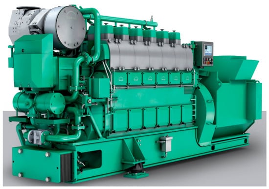
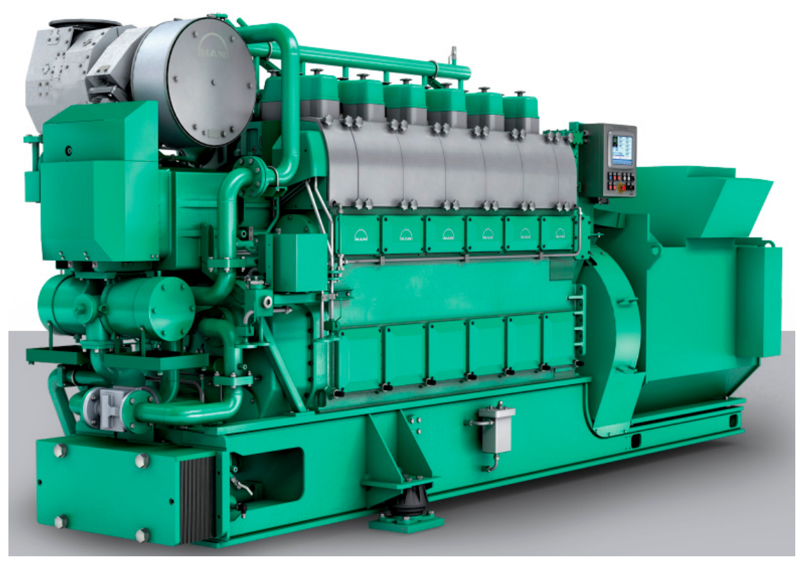
The experimental setup employed a MAN L23/30H four-stroke marine diesel engine (manufactured by Zibo ZC Diesel, Zibo, China) as the test platform. Key specifications of this large-bore propulsion system are detailed in Table 1. This powerplant incorporates a common rail direct injection mechanism, an electronic hydraulic fuel delivery system, and a secure fuel supply configuration. The engine’s forced induction system features an ABB A165-L single-stage turbocharger from ABB Switzerland (Baden, Switzerland). Thermal management is handled by a KLQ50H single-stage water-cooled intercooler manufactured in Zibo, China. MAN L23/30H four-stroke marine engine is illustrated in Figure 1.
Table 1.
Basic engine parameters.
Figure 1.
MAN L23/30H four-stroke marine engine. Image source: MAN Energy Solutions, L23/30H medium-speed four-stroke genset engine (https://www.man-es.com/marine/campaigns/four-stroke-small-bore-engines accessed on 1 September 2026), reproduced with permission.
The valve timing used in the simulation is summarized as follows: since the simulations were performed as closed-cycle calculations (Section 2.3), only the charge-trapping and exhaust-opening events are relevant: intake valve closing (IVC) at −156°CA ATDC and exhaust valve opening (EVO) at 126°CA ATDC, where 0°CA ATDC denotes the firing top dead center. The intake valve opening (IVO) and exhaust valve closing (EVC) events were not modeled because the gas-exchange process was excluded from the computational domain.
2.2. Model Establishment
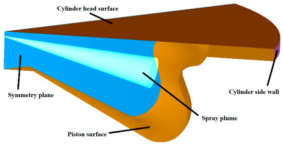
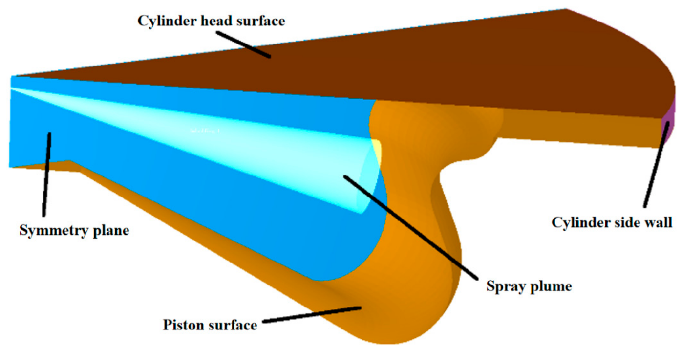
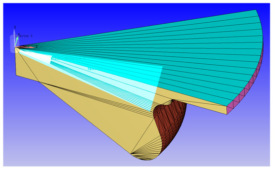
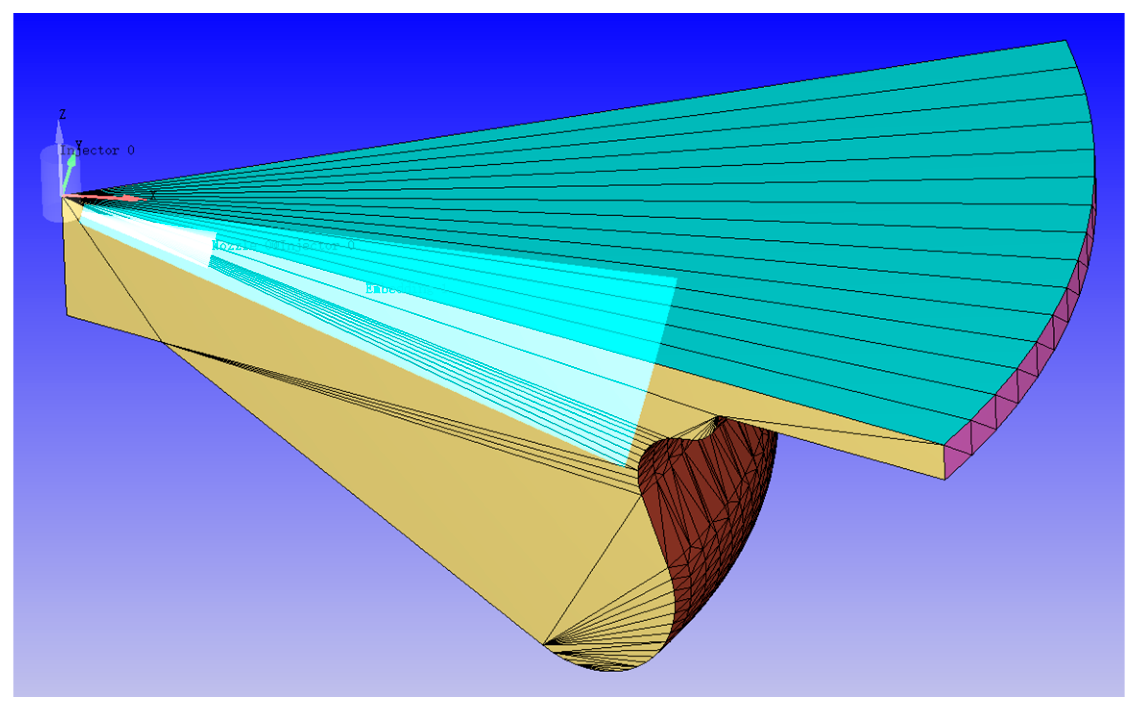
Turbulence characteristics during valve events were dynamically calibrated according to the engine’s geometric configuration. The numerical framework for in-cylinder flow field analysis integrated Reynolds-Averaged Navier–Stokes (RANS) equations with the renormalization group (RNG) k-ε turbulent closure scheme [15]. Droplet disintegration physics were modeled through the Kelvin-Helmholtz/Rayleigh-Taylor (KH-RT) hybrid mechanism, with calibration parameters derived from established spray atomization research by Shi et al. [16], as detailed in Table 2. The computational approach incorporated Frossling’s evaporation dynamics and the NTC inter-droplet interaction model. For combustion modeling, the detailed chemistry-based SAGE solver was implemented, enabling flexible selection of chemical kinetic mechanisms and thermodynamic databases based on simulation objectives. This combustion module maintained activation throughout the fuel injection duration until complete combustion termination. The complete set of physical submodels employed in this simulation is systematically documented in Table 2. The three-dimensional combustion chamber geometry configuration is visually presented in Figure 2 and Figure 3.
Figure 2.
Model of the combustion chamber.
Figure 3.
Simulation model.
In the present simulations, the detailed chemical kinetic mechanism of Xu et al. [17], the ammonia/n-heptane skeletal chemical kinetic mechanism (69 species and 389 reactions, in which n-heptane serves as the diesel surrogate), was implemented in the SAGE solver to resolve the combustion chemistry and the formation of nitrogen-containing species, including NO, NO2, N2O, and unburned NH3. The validation range of the mechanism covers temperature, pressure, and equivalence-ratio ranges covering engine-relevant conditions; the mechanism was validated against ignition delay times (shock tubes and rapid compression machines), laminar burning velocities (heat flux burners and spherical flame vessels), and jet-stirred reactor species profiles for pure NH3, NH3/H2, and NH3/n-heptane mixtures, as reported in the validation matrix of Xu et al. [17]. To avoid ambiguity regarding the nitrogen-chemistry modeling: for the pure-diesel baseline, the thermal NOx was evaluated with the Extended Zeldovich model listed in Table 2; in the ammonia/diesel dual-fuel simulations, NO, NO2, and N2O were calculated directly by the detailed chemical kinetic mechanism within the SAGE solver, because the NHi-radical reduction pathways cannot be captured by the thermal NOx model alone; the Extended Zeldovich model was therefore deactivated in the dual-fuel simulations.
Redefine the in-cylinder turbulence parameters according to the engine parameters and estimate the turbulence kinetic energy from
Specify the turbulence length scale as
linit = 0.025 ⋅ bore
Calculate the turbulence dissipation rate from
Table 2.
Selection of simulation submodel.
The selected physical models are listed in Table 2. Based on the introduction of this mechanism, while maintaining the diesel injection mode unchanged, the mass of ammonia and diesel were calculated using formulae by keeping the total fuel energy constant [26]. The diesel injection duration was adjusted to ensure a constant diesel injection pressure. Subsequently, ammonia was introduced into the intake mixture to form a dual-fuel simulation model with diesel through premixed combustion. When setting the fuel injection quantity, the total fuel energy was calculated based on a diesel injection quantity of 1.25 g under the original engine’s 100% load condition (with a diesel heating value of 45 MJ/kg) [3]. Then, according to the AER and ammonia heating value (18.6 MJ/kg), the amounts of ammonia and diesel fuel for different operating conditions were determined [27].
With respect to the injection settings: diesel was injected through the fuel injector equipped with 8 nozzle holes of 0.33 mm diameter at a constant injection pressure of 350 bar, and the injection duration was adjusted according to the pilot diesel mass per cycle so as to maintain the injection pressure; the ammonia fuel was supplied as a premixed charge into the intake mixture and the diesel injection followed a single-pulse (rectangular) rate shape. The diesel injection timing was fixed at −10°CA ATDC for all the dual-fuel operating conditions analyzed in this study.
2.3. Mesh Generation Methodology
CONVERGE’s computational framework provides three distinct mesh generation strategies: fundamental grid configuration, dynamic Adaptive Mesh Refinement (AMR), and predefined localized refinement. The AMR technique automatically enhances spatial resolution through continuous monitoring of flow velocity, thermal gradients, and chemical species distribution, permitting user-defined resolution adjustments across temporal and spatial domains [28]. Fixed embedding facilitates targeted mesh optimization in critical zones including injector orifices, piston crowns, and near-wall viscous sublayers. These mesh optimization techniques maintain operational autonomy, enabling customized temporal activation and refinement intensity configuration, with parallel computation enabling micron-level mesh precision.
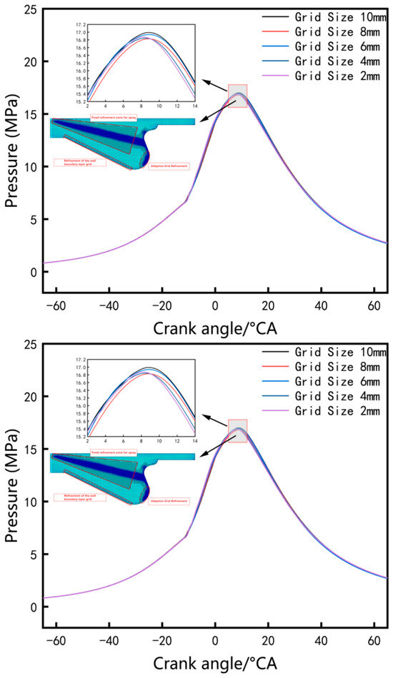
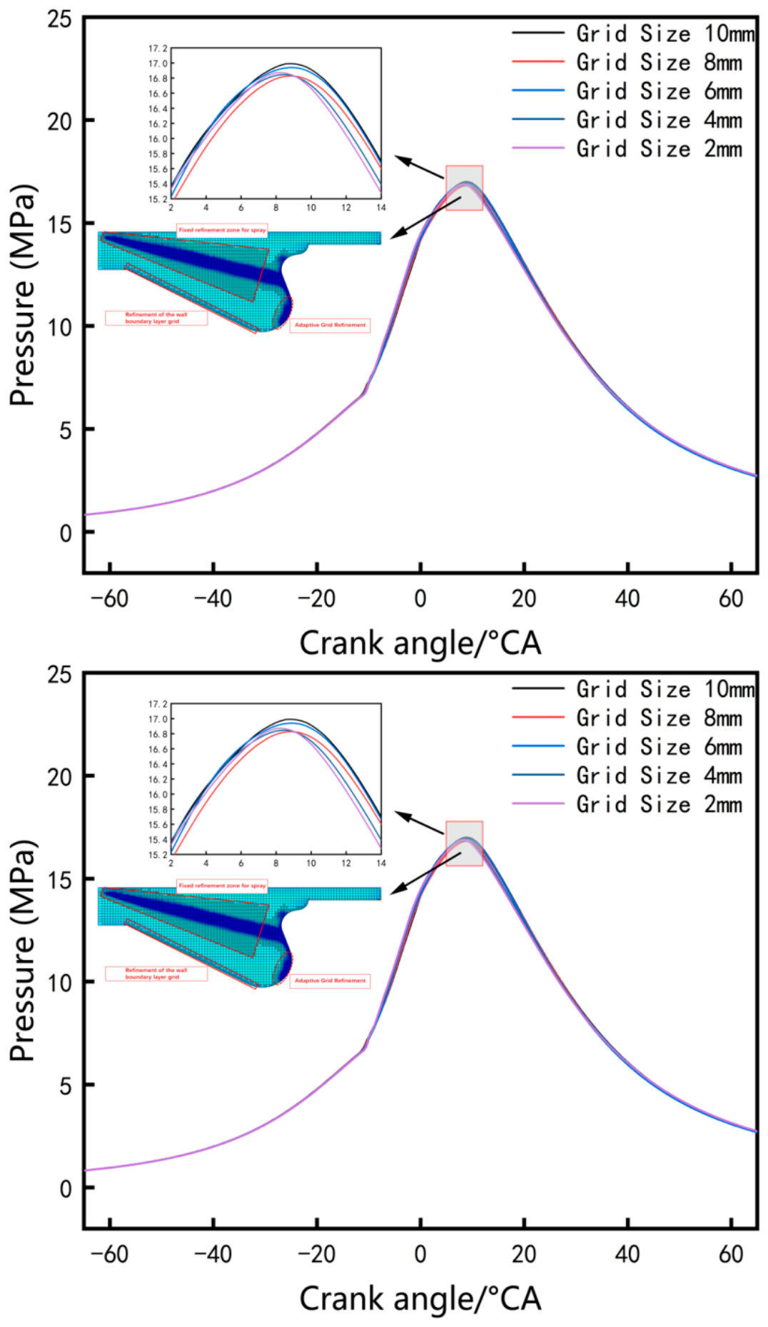
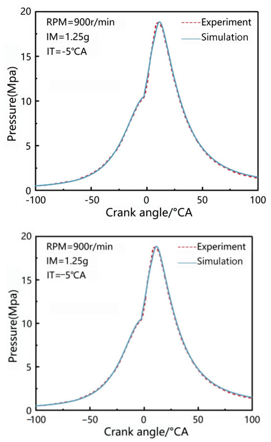
The numerical validation process utilized empirical data from baseline diesel combustion experiments in the prototype power unit. Computational verification involved parametric evaluation of four fundamental cell dimensions: 8 mm, 6 mm, 4 mm, and 2 mm. Employing the 4 mm baseline configuration, boundary layer resolution was enhanced through dual-level AMR implementation, while fuel atomization zones received triple-layer fixed embedding optimization. Figure 2 visually demonstrates the refined spray-cloud patterns and near-wall mesh morphology during compression stroke termination near TDC.
The grid division strategy adopted in this work is illustrated in Figure 4. The numerical datasets originated from Zhenjiang CSSC Marine Power Co., Ltd. (Zhenjiang, China). Experimental benchmarking employed cycle-resolved in-cylinder pressure traces acquired from dynamometer tests to verify computational modeling accuracy. The computational results exhibited a discrepancy within 2% relative to the experimental data, evaluated as the relative error of the peak in-cylinder pressure across the operational envelope, with particular precision in capturing critical thermodynamic inflection points during rapid pressure escalation. This validation confirms the redesigned combustion volume geometry, developed through reverse-engineering of mechanical specifications and optimized spatial discretization, possesses sufficient fidelity for predictive cycle analysis. Following comprehensive evaluation of computational fluid dynamics (CFD) solution sensitivity versus hardware constraints, the 4 mm baseline spatial discretization parameter was universally adopted across all computational domains and boundary condition variations.
Figure 4.
Grid division strategy.
A quantitative grid-independence study was performed by comparing the computed in-cylinder pressure trace, peak cylinder pressure, CA50, and indicated thermal efficiency for base mesh sizes of 8 mm, 6 mm, 4 mm, and 2 mm under the baseline diesel condition. The differences between the 4 mm and 2 mm meshes in the peak cylinder pressure, CA50, and indicated thermal efficiency were within 1%, demonstrating that the 4 mm base mesh combined with two-level AMR and triple-layer fixed embedding provides a satisfactory compromise between accuracy and computational cost. With these refinements, the minimum cell size in the near-wall and spray regions was 0.5 mm.
All simulations were performed as closed-cycle calculations: a homogeneous premixed ammonia–air charge was assumed to be trapped in the cylinder at intake valve closure (IVC), and the gas-exchange process was not explicitly resolved (the valve timing is summarized in Section 2.1). The initial thermodynamic state was set to an initial pressure of 2 bar and an initial temperature of 350 K for the 100% load condition and to an initial pressure of 1.54 bar and an initial temperature of 350 K for the 50% load condition, and the initial turbulence field was specified by estimating the turbulence kinetic energy from Equation (1), the turbulence length scale from Equation (2), and the turbulence dissipation rate from Equation (3), according to the engine geometry. During the closed-cycle simulation, the in-cylinder turbulent motion is generated and sustained by the piston motion and the fuel spray, and is resolved with the RANS/RNG k-ε model and no initial swirl ratio or tumble ratio was prescribed.
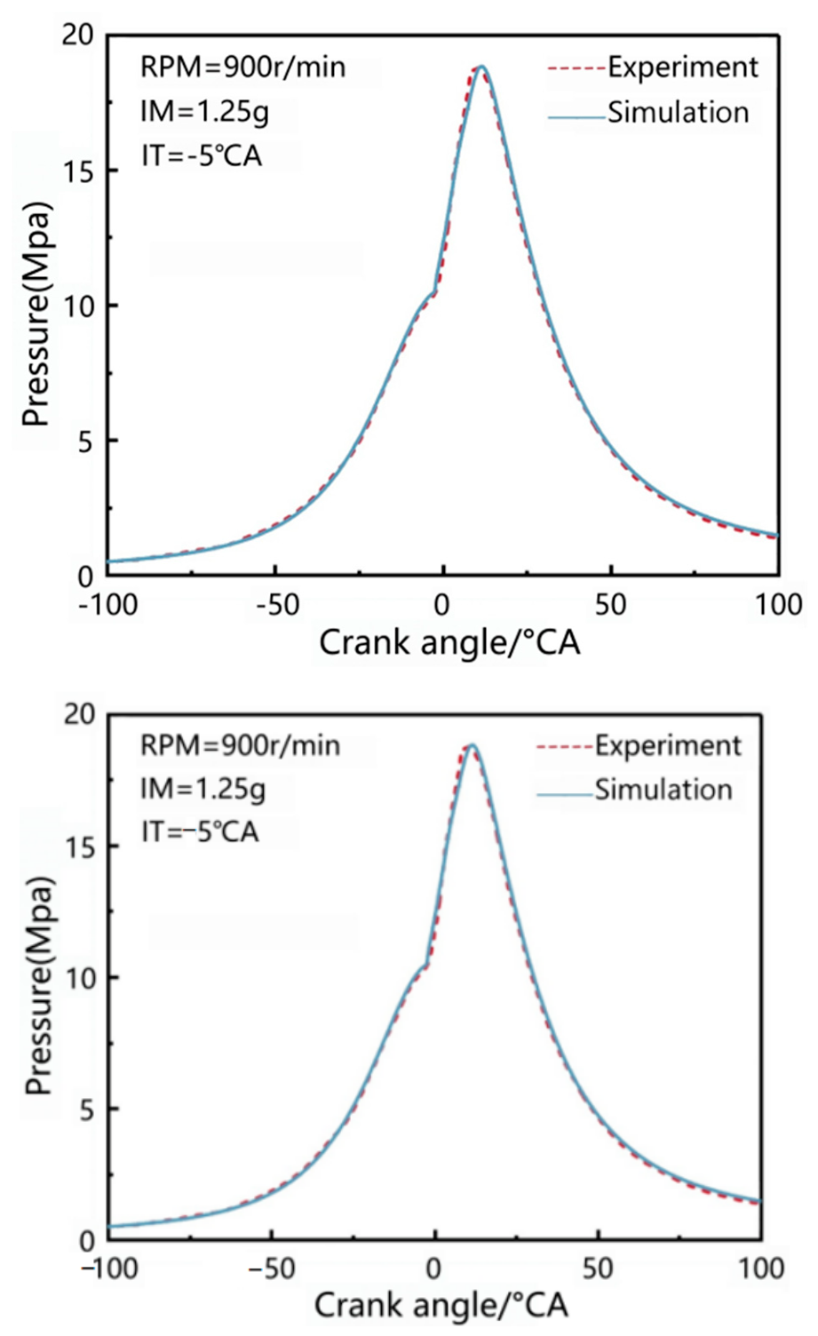
In addition to the pure-diesel baseline validation, the predictive capability of the model for ammonia/diesel dual-fuel combustion was assessed against published experimental and numerical data. The simulated trends, namely the extension of ignition delay, the reduction in peak cylinder pressure, the deterioration of combustion efficiency, and the increase in unburned NH3 and NOx emissions with increasing AER, are qualitatively consistent with the experimental observations reported for ammonia/diesel dual-fuel engines in the literature [5,9,10]. The present validation mainly concerns the in-cylinder pressure under pure-diesel operation; the predictions of N2O and unburned NH3 depend strongly on the chemical kinetic mechanism and on the initial and boundary conditions. Accordingly, the emission results reported in this study are regarded as qualitative rather than quantitative. The validation of the original diesel engine model is presented in Figure 5.
Figure 5.
Validation of the original diesel engine model.
2.4. Analysis of Simulation Results
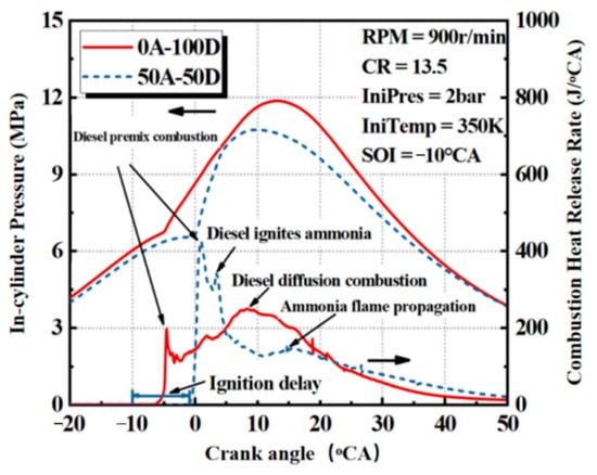
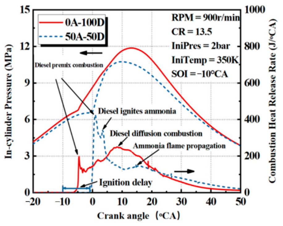
Figure 6 presents the calculated results of in-cylinder mean pressure and combustion heat release rate curves for pure diesel and a 50% AER under 100% load conditions. As illustrated, pure diesel combustion is characterized by two stages: premixed combustion and diffusion combustion. When ammonia is premixed, the combustion process can be divided into diesel premixed combustion (with an increased proportion due to the extended ignition delay period), diesel-ignited surrounding premixed ammonia (accompanied by a small amount of diesel diffusion combustion), and the propagation of ammonia combustion flame.
Figure 6.
Cylinder pressure and heat release rate under pure diesel and 50% ammonia substitution conditions.
Under pure diesel conditions, there is approximately a 5°CA ignition delay period after diesel is injected into the combustion chamber before ignition and combustion occur. During this ignition delay period, a portion of combustible premixed gas forms, which rapidly burns upon reaching ignition conditions, resulting in a peak heat release from diesel premixed combustion. Typically, the proportion of diesel premixed combustion is relatively small, leading to a lower peak heat release. As diesel injection continues, the flame develops along with the injection, creating a “spray-and-burn” phenomenon known as diffusion combustion, which is the primary combustion mode in diesel engines.
In the ammonia/diesel dual-fuel combustion mode, the presence of premixed ammonia fuel in the cylinder reduces the oxygen concentration in the combustion chamber, extending the ignition delay period from approximately 5°CA to around 10°CA. This extended ignition delay increases the amount of premixed diesel, coupled with the presence of premixed ammonia fuel, leading to an increased peak heat release during diesel premixed combustion. Subsequently, the high-temperature fuel spray rapidly ignites the surrounding premixed ammonia fuel, resulting in the emergence of a second heat release peak. After ignition, the premixed ammonia fuel gradually diffuses towards the unburned regions in the combustion chamber. However, due to ammonia’s slow flame propagation speed (with a maximum laminar flame speed of 7 cm/s), the subsequent combustion heat release of ammonia is delayed, characterized by a prolonged heat release duration and a lower peak heat release.
As evident from the cylinder pressure curve, ammonia’s slow flame propagation speed reduces the combustion heat release rate and may also decrease combustion efficiency. Therefore, compared to pure diesel combustion, the peak in-cylinder mean pressure decreases when ammonia is blended.
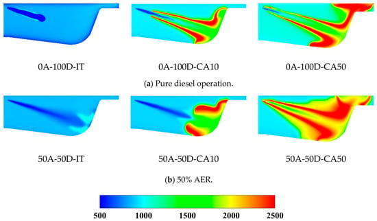
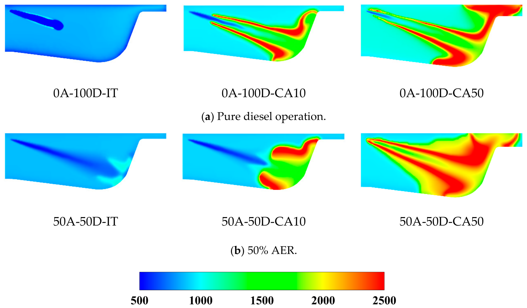
From the heat release rate curves, it is evident that the combustion phase shifts upon the addition of ammonia fuel. Therefore, in analyzing the distribution of physical fields within the cylinder, this study selects three representative time points during the fuel combustion process for comparative analysis: IT (Ignition Timing, the moment when ignition first occurs), CA10 (the moment when the accumulated heat release reaches 10% of the total heat release from fuel combustion), and CA50 (the moment when the accumulated heat release reaches 50% of the total heat release from fuel combustion). These specific time points vary under different AER. By choosing these representative moments instead of fixed times, we aim to better compare and analyze the impact of various AER on the distribution characteristics and variation patterns of physical fields within the cylinder.
Figure 7 illustrates the in-cylinder temperature field distribution under 100% load conditions for pure diesel and a 50% AER. A comparative analysis of the in-cylinder temperature distribution under pure diesel and 50% AER conditions reveals that, during pure diesel combustion, the ignition point is located in the middle of the spray plume, where the entrainment capability of the plume is strongest, enabling it to entrain a significant amount of air and thus form a combustible mixture first, reaching the ignition conditions. However, when ammonia is blended, the reduction in oxygen concentration within the cylinder slows down the ignition process, extending the ignition delay period. As a result, better mixing conditions are achieved at the end of the plume, making it the first region to ignite. Therefore, in the pure diesel case, the high-temperature combustion region spreads simultaneously from the middle of the plume towards both the upstream and downstream directions. In contrast, for the ammonia/diesel dual-fuel combustion case, the high-temperature region first appears at the end of the plume and then gradually spreads towards the upstream as fuel injection continues. At the CA50 moment, the high-temperature region covers the entire plume. In the ammonia/diesel dual-fuel combustion scenario, since the combustion chamber is filled with premixed ammonia fuel, the subsequent high-temperature flame propagates to other unburned regions of the combustion chamber.
Figure 7.
Distribution of in-cylinder temperature fields.
Regarding the jet development in cases (a) and (b) of Figure 7, it should be noted that the diesel injection pressure and the nozzle geometry were identical in both cases; hence, the initial jet velocity at the nozzle exit is the same. The different jet behaviors—in particular, the fact that ignition occurs at the middle of the spray plume in the pure-diesel case but at the plume end in the 50% AER case—arise from the modified ambient charge: the presence of the premixed ammonia reduces the oxygen concentration and changes the mixture formation and ignition kinetics in the jet region, rather than from any change in the injection itself.
Through calculation and analysis, it is demonstrated that the original engine simulation model established in this chapter achieves a good fit with the experimental cylinder pressure data. Furthermore, the ammonia/diesel dual-fuel simulation model, built upon the original engine model, can accurately and reasonably predict the combustion characteristics and temperature distribution of ammonia and diesel. Therefore, the simulation models established in this chapter are capable of meeting the requirements for subsequent analysis and research.
3. Results and Discussion
3.1. Analysis of Combustion Characteristics with Varying AER
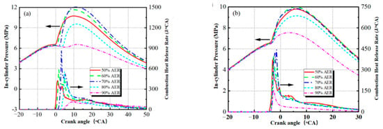
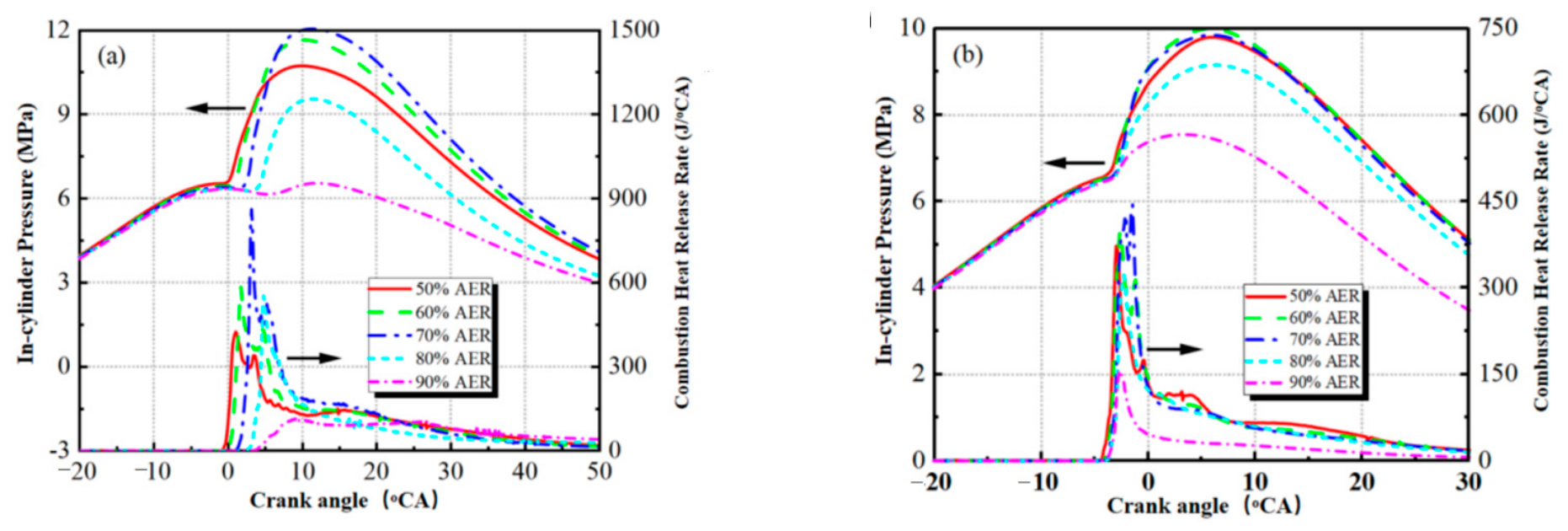
The unique fuel properties of ammonia significantly influence in-cylinder ignition characteristics and heat release processes. This study investigates the combustion behavior of ammonia/diesel dual-fuel blends with substitution ratios ranging from 50% to 90% under medium (50% load) and high (100% load) engine operating conditions. As shown in Figure 8, the cylinder pressure and heat release rate profiles exhibit distinct variations across different AER. Here, the ammonia substitution ratio is defined as the percentage of ammonia energy relative to the total fuel energy input. All simulations were conducted at a constant engine speed of 900 rpm with a compression ratio of 13.5, employing a pilot diesel injection timing of 10°CA before top dead center (TDC, i.e., −10°CA ATDC) for the dual-fuel operating conditions; the −5°CA injection timing listed in Table 1 corresponds to the original engine’s baseline diesel calibration used for model validation.
Figure 8.
In-cylinder pressure and heat release rate curves at varied AER (100% load and 50% load). (a) 100% load; (b) 50% load. Conditions: Engine Speed = 900 r/min, Compression Ratio (CR) = 13.5, Fuel Injection Timing = −10°CA.
The dual-fuel combustion process demonstrates two distinct phases: (1) auto-ignition of the diesel pilot fuel, followed by (2) flame propagation combustion of the premixed ammonia–air mixture. This staged combustion mechanism arises from the substantial difference in chemical reactivity between the high-cetane diesel fuel (acting as an ignition promoter) and the low-reactivity ammonia fuel. The heat release curves reveal that the initial diesel-dominated phase exhibits rapid combustion with concentrated heat release, while the subsequent ammonia combustion phase displays prolonged duration with attenuated heat release rates, characteristic of slower flame propagation in ammonia–air mixtures.
In the present dual-fuel strategy, the ignition phase is governed by the pilot diesel injection: owing to the high auto-ignition temperature and low reactivity of ammonia, the premixed ammonia–air charge cannot self-ignite under the compression conditions investigated, and the combustion phasing is therefore controlled by the auto-ignition of the pilot diesel, which in turn depends on the diesel injection timing, the pilot quantity, and the in-cylinder thermodynamic state (pressure, temperature, and oxygen concentration).
As illustrated in Figure 8, the combustion characteristics of ammonia/diesel dual-fuel engines exhibit significant variations with increasing AER. The peak cylinder pressure initially rises and subsequently declines as AER increases, a trend consistently observed under both 50% and 100% load conditions. This indicates that moderate AER elevation enhances combustion activity, whereas excessive substitution (beyond an optimal threshold) markedly reduces heat release rates and deteriorates combustion performance. The initial increase in peak pressure at lower AER levels is attributed to the elevated fuel equivalence ratio of the ammonia–air premixed charge within the cylinder, which facilitates ammonia ignition triggered by the diesel flame. This mechanism promotes accelerated early-stage heat release rates and higher peak heat release, thereby amplifying in-cylinder pressure. Furthermore, the heat release rate curves reveal a progressive delay in ignition timing with higher AER, reflecting an extended ignition delay period (defined as the interval between diesel injection initiation and combustion onset). This phenomenon is more pronounced under full-load (100%) operation. The delayed ignition arises from the combined effects of an enriched premixed charge (higher equivalence ratio) and reduced oxygen concentration at elevated AER levels. The oxygen deficit suppresses the autoignition kinetics of diesel fuel, thereby retarding combustion initiation and prolonging the ignition delay phase.
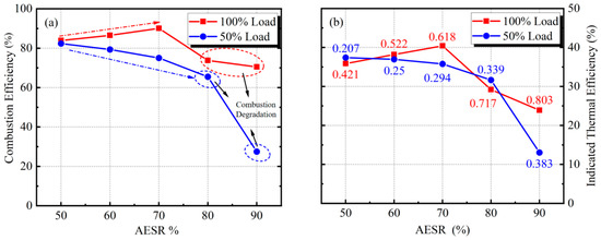
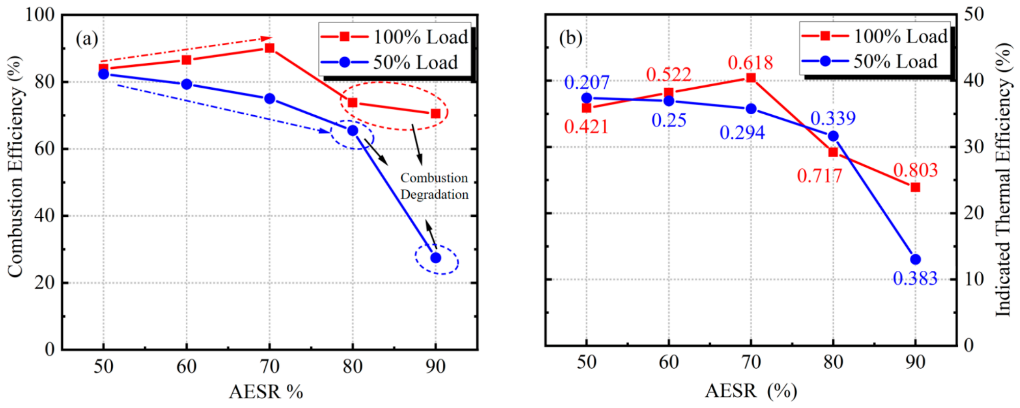
As demonstrated in Figure 8, combustion performance does not deteriorate at initial stages of AER elevation; however, when AER exceeds 90%, in-cylinder fuel combustion characteristics degrade significantly, manifested by flattened heat release rate curves and markedly reduced peak cylinder pressure. These trends are directly corroborated by the calculated combustion efficiency and indicated thermal efficiency values presented in Figure 9. Under full-load (100%) conditions, increasing AER from 50% to 70% enhances both combustion efficiency and indicated thermal efficiency due to the elevated premixed equivalence ratio of ammonia, which improves its ignition and combustion behavior. Beyond this threshold, however, the drastic reduction in pilot diesel quantity (even under rich ammonia–air mixtures) leads to insufficient ignition energy, causing a sharp decline in ammonia combustion efficiency. This adverse effect of reduced diesel injection volume on ammonia combustion is exacerbated at 50% load. Specifically, at 50% load, combustion efficiency and indicated thermal efficiency rapidly decrease as AER rises from 50% to 90%, primarily because the pilot diesel quantity (half of that at full load) becomes inadequate to reliably ignite the ammonia–air mixture. Additionally, combustion efficiencies at 50% load are consistently lower than those at 100% load across all AER levels, attributable to the leaner premixed ammonia–air charge (lower equivalence ratio) under partial-load operation. Figure 9b quantifies the premixed ammonia equivalence ratios, defined as the ratio of the actual fuel-to-air mass ratio to the stoichiometric fuel-to-air ratio (excluding diesel contribution). It is worth clarifying that the equivalence ratio φ is the inverse of the air-excess ratio λ (φ = 1/λ) for the ammonia–air premixture (the diesel contribution being excluded); thus, φ = 0.9 corresponds to λ = 1.11 and φ = 0.7 corresponds to λ = 1.43, i.e., misfire occurs on the lean side of stoichiometry, where the laminar flame speed of ammonia is too low to sustain stable combustion. At 50% load, equivalence ratios range between 0.2 and 0.3, representing excessively lean conditions for ammonia combustion. Such lean mixtures impede ammonia ignition, reduce flame propagation velocity, and prolong combustion duration, collectively degrading combustion efficiency.
Figure 9.
The combustion efficiency and indicated thermal efficiency (100% and 50% load) at varying AER. Conditions: Engine Speed = 900 r/min, Compression Ratio (CR) = 13.5, Fuel Injection Timing = −10°CA; Initial pressure = 2 bar, Initial temperature = 350 K. (a) Combustion Efficiency; (b) indicated thermal efficiency.
It should be emphasized that, for ammonia-fueled engines, a high combustion efficiency is not only an indicator of energy conversion but also a prerequisite for safety and emission compliance: unburned ammonia is toxic to human health, and ammonia slip must be minimized in practical applications [29]. Combustion efficiencies below 95% would therefore be unacceptable for production engines. The substantial decrease in combustion efficiency observed at high AER—particularly at 50% load, where it drops below 30%—clearly demonstrates that overly high substitution ratios must be avoided, and that the pilot diesel quantity and injection strategy require further optimization to suppress unburned NH3 emissions.
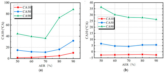
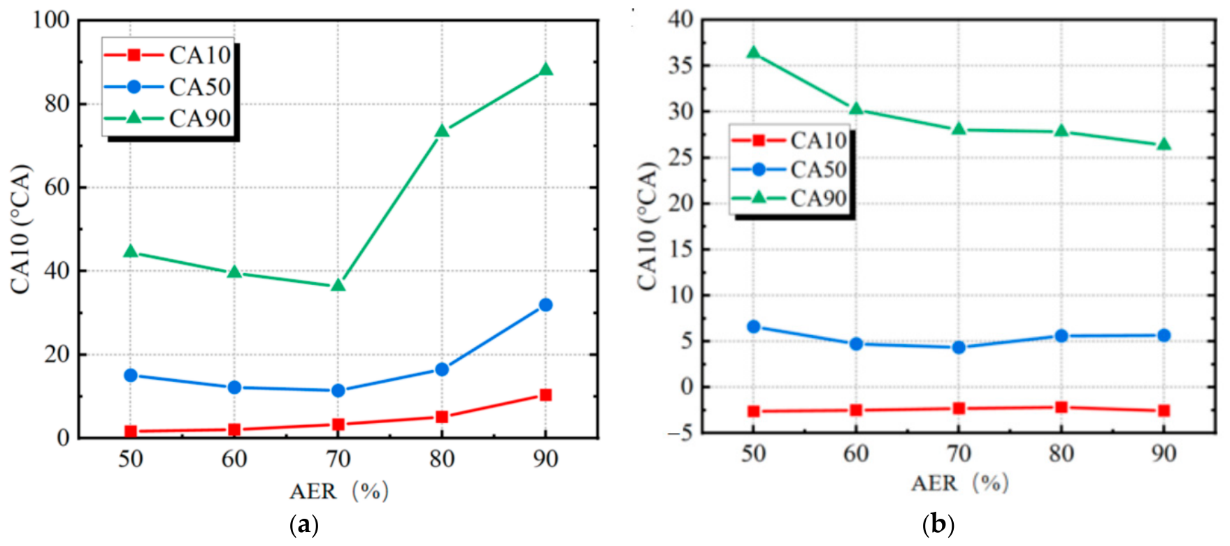
Further analysis of the ammonia/diesel dual-fuel combustion process reveals significant differences in combustion characteristics under different load conditions, with the proportion of ammonia fuel also exerting a notable influence on combustion behavior. As shown in Figure 10, CA10, CA50, and CA90 under different ammonia replacement ratios are defined as the crank angles corresponding to 10%, 50%, and 90% of the cumulative heat release relative to the total heat release during fuel combustion. CA10, CA50, and CA90 respectively characterize the initial combustion phase, the main combustion phase, and the near-complete combustion phase. Computational results demonstrate that under 100% load, the higher concentration of ammonia-premixed mixture in the cylinder delays the ignition timing of diesel, resulting in a later CA10 compared to the 50% load condition. Additionally, both CA50 and CA90 under 100% load exhibit significant retardation relative to the 50% load case. This indicates that ammonia/diesel dual-fuel combustion under high-load conditions generally exhibits prolonged combustion duration and slower combustion speed.
Figure 10.
CA10, CA50, and CA90 under different AER (100% Load and 50% Load). (a) 100% load; (b) 50% load. Conditions: Engine Speed = 900 r/min, Compression Ratio (CR) = 13.5, Fuel Injection Timing = −10°CA.
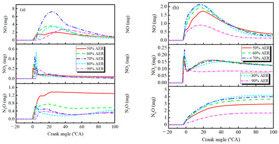
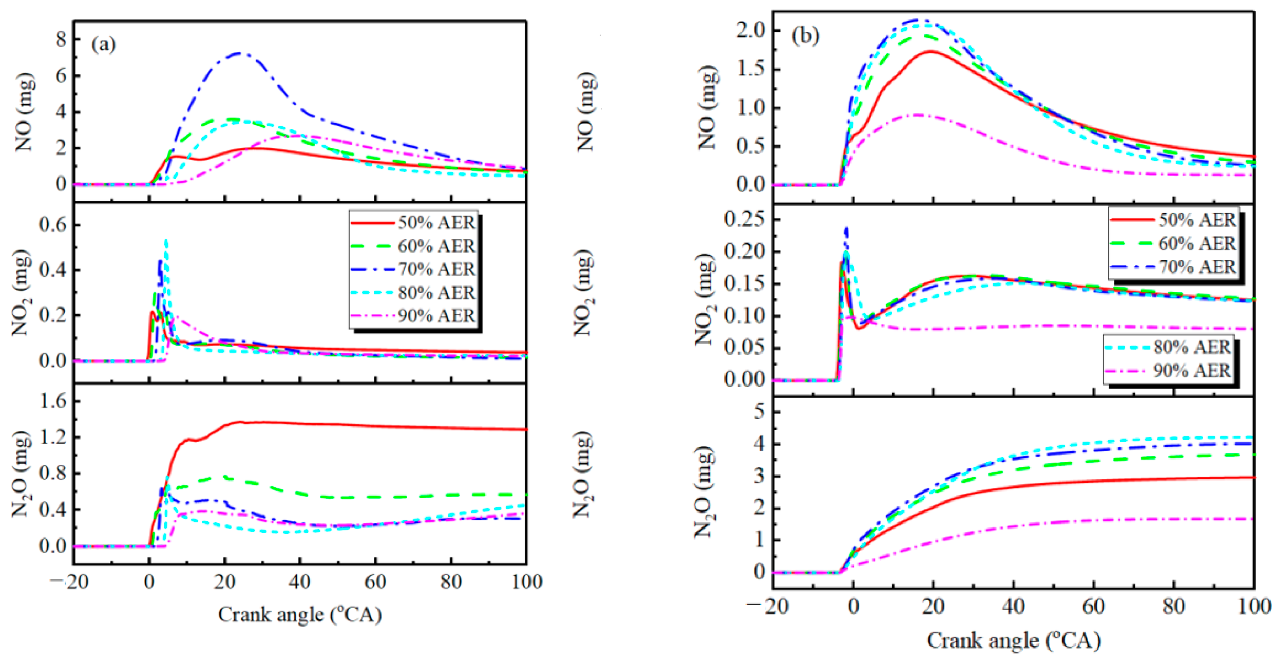
In addition to its impact on combustion characteristics, the ammonia replacement ratio also significantly influences the formation of in-cylinder pollutants. Here, we focus on analyzing three key nitrogen oxides (NO, NO2, and N2O) generated during ammonia combustion. Figure 11 illustrates the formation history and variation trends of these nitrogen oxides during in-cylinder combustion. The results show that NO in ammonia/diesel dual-fuel combustion exhibits a non-monotonic pattern, first increasing and then decreasing. The accumulated NO mass initially rises, peaks, and gradually stabilizes during the late combustion phase. The rapid NO generation in the early stage is attributed to the rapid combustion of diesel and ammonia ignition, which produces substantial NO. However, ammonia exhibits a reduction effect on NO, where NHi radicals generated during ammonia combustion react with and consume NO, leading to its subsequent decline.
Figure 11.
Variation patterns of in-cylinder NO, NO2, and N2O formation under different AER (100% Load and 50% Load). (a) 100% load; (b) 50% load. Conditions: Engine Speed = 900 r/min, Compression Ratio (CR) = 13.5, Fuel Injection Timing = −10°CA.
NO2 follows a similar pattern: it is abundantly produced in the early stage, significantly reduced during ammonia combustion reactions, and may rise again in the late combustion phase. This is because NHi radicals can also reduce NO2. Consequently, the formation histories of NO and NO2 are governed by the coupled effects of diesel combustion, ammonia combustion, and ammonia’s reduction mechanisms, resulting in non-monotonic trends in their accumulated masses.
N2O is primarily generated through reactions between NHi radicals and NO/NO2, explaining its significant production during ammonia combustion. As a characteristic product of ammonia combustion, N2O is absent in traditional carbon-based fuel combustion, where nitrogen oxides mainly originate from atmospheric N2 oxidation. Figure 11 reveals that under 100% load, N2O exhibits fluctuating trends during combustion, whereas under 50% load, its concentration gradually increases without decline. This is attributed to the higher ammonia content under full-load conditions: excess ammonia not only reacts with NO and NO2 to form N2O but also further converts N2O into N2, leading to N2O reduction phenomena in high-load operations.
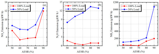
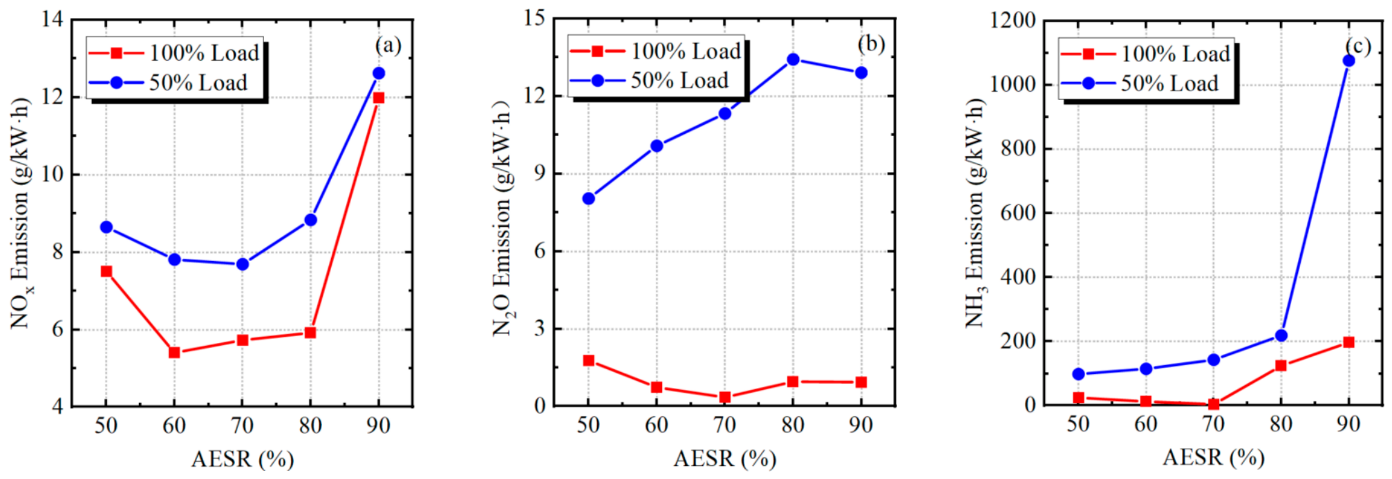
The in-cylinder evolution of unburned NH3 was also tracked in the simulations, and its engine-out emission behavior under different AER is presented in Figure 12. The final in-cylinder level of unburned NH3 rises markedly with increasing AER, which is consistent with the decreased combustion efficiency shown in Figure 9 and with the elevated unburned NH3 emissions at AER = 90% shown in Figure 12.
Figure 12.
NOx emissions, N2O emissions, and unburned NH3 emissions under different AER (100% load and 50% load). (a) Variation of NOx emission. (b) Variation of N2O emission. (c) Variation of NH3.
Emission characteristics under 100% and 50% load at different AESR. Conditions: Initial temperature = 350 K. (a) Variation of NOx emission; (b) Variation of N2O emission; (c) Variation of NH3 emission. By comparing the computational results under different loads in Figure 11, it can be observed that the peak NO and NO2 formation under 100% load exceeds that of the 50% load condition, while N2O generation is significantly lower at full load. This phenomenon arises not only from the higher ammonia fuel quantity at 100% load but also from the critical influence of in-cylinder combustion temperature on the formation characteristics of NO, NO2, and N2O. NO primarily forms under high-temperature oxygen-rich conditions, NO2 generation occurs at lower temperatures than NO, and N2O predominantly forms in the low-temperature range of 1000–1500 K. At 100% load, the higher fuel quantity elevates in-cylinder temperatures, promoting greater NO formation while substantially suppressing N2O generation.
To further clarify the load- and AER-dependent (non-monotonic) trends of NO, NO2, and N2O formation, the in-cylinder thermal environment was examined in detail. Under 100% load, the higher mean in-cylinder temperature promotes thermal NO formation, whereas under 50% load the lower temperature level, combined with the ammonia-derived NHx radicals, favors the NO-reduction and N2O-formation pathways (Figure 13 and Figure 14).
Figure 13.
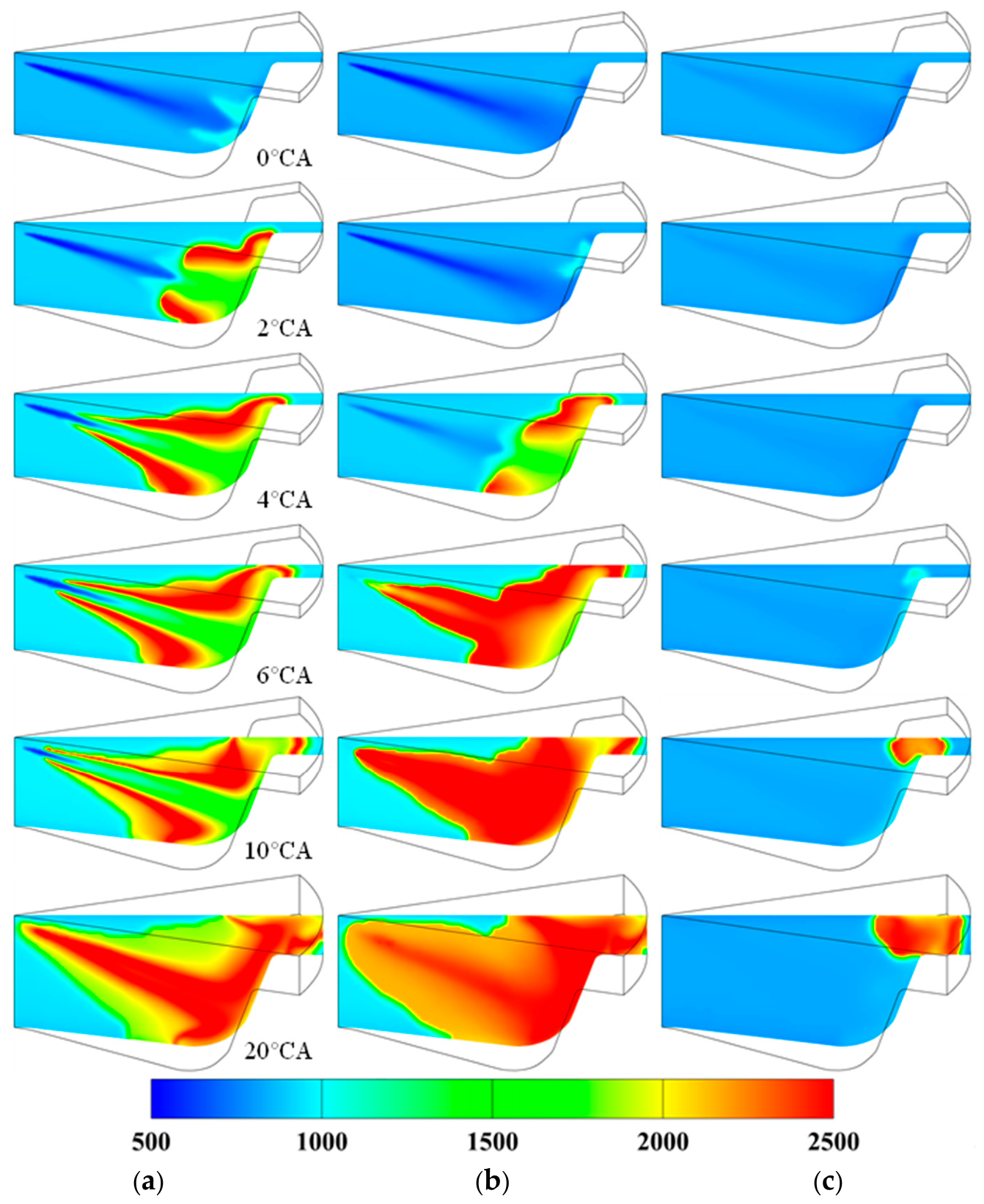
Temperature distribution under different AER (100% Load). (a) AER = 50% (b) AER = 70% (c) AER = 90%.
Figure 14.
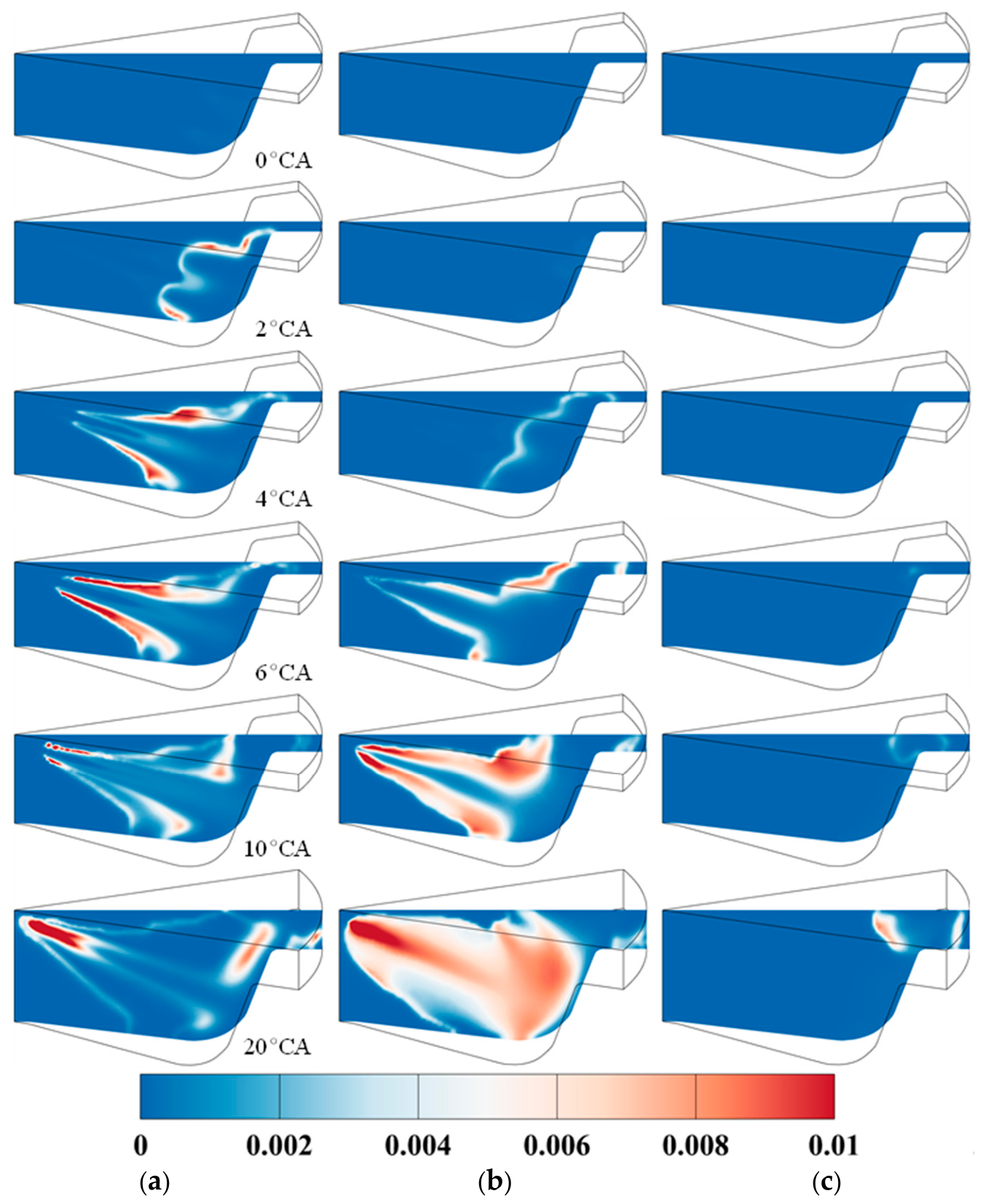
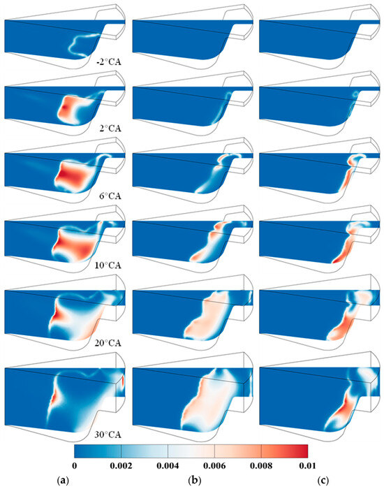
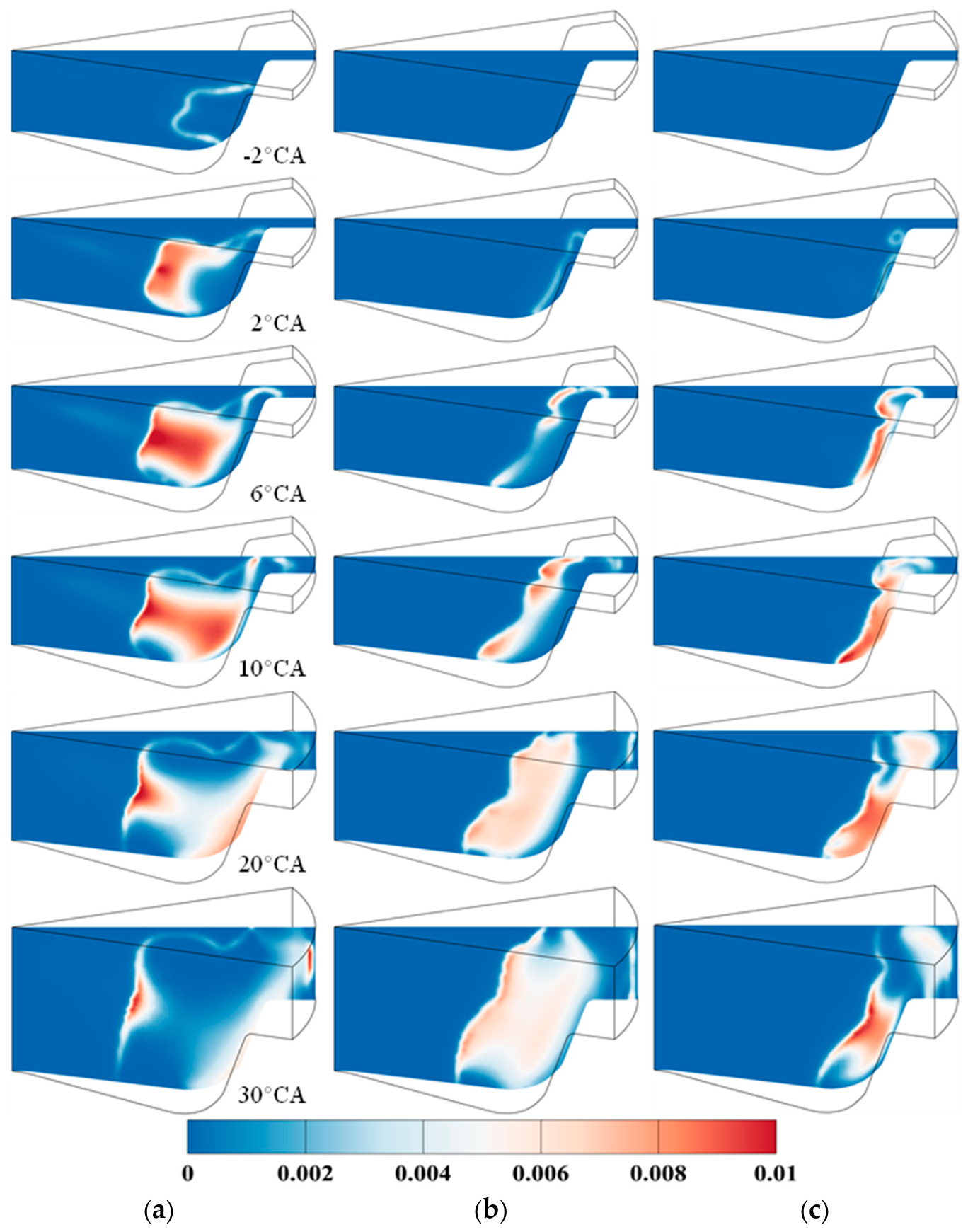
NOx distribution under different AER (100% load). (a) AER = 50% (b) AER = 70% (c) AER = 90%.
For engine pollutant emission evaluation, specific emissions (g/kW·h) are typically adopted as the metric. This unit normalizes pollutant quantities against engine output power, eliminating discrepancies caused by engine type and displacement differences, thereby enabling standardized emission assessments. Figure 12 displays the final normalized emissions of NOx (NO + NO2), N2O, and unburned NH3. Pollutant emission values are measured at exhaust valve opening, while engine output power is calculated based on indicated work during compression and expansion strokes. All emission values reported in Figure 11 and Figure 12 are computed directly from the in-cylinder species masses at exhaust valve opening and are expressed on a dry basis. The results demonstrate superior NOx and unburned NH3 emissions under high-load conditions. Although NOx emissions are higher at 100% load, the significantly improved indicated thermal efficiency and higher power output result in lower normalized emissions compared to the 50% load case. Additionally, elevated in-cylinder temperatures at full load reduce N2O formation, and combined with higher output power, the normalized N2O emissions under 100% load are far lower than those at 50% load. Unburned NH3 emissions correlate with combustion efficiency, and higher combustion efficiency at full load leads to reduced NH3 emissions. Notably, when the ammonia replacement ratio reaches 90%, both NOx and unburned NH3 emissions increase substantially, while N2O emissions under 50% load also rise significantly. This indicates that high ammonia replacement ratios not only degrade combustion performance but also significantly worsen engine emissions.
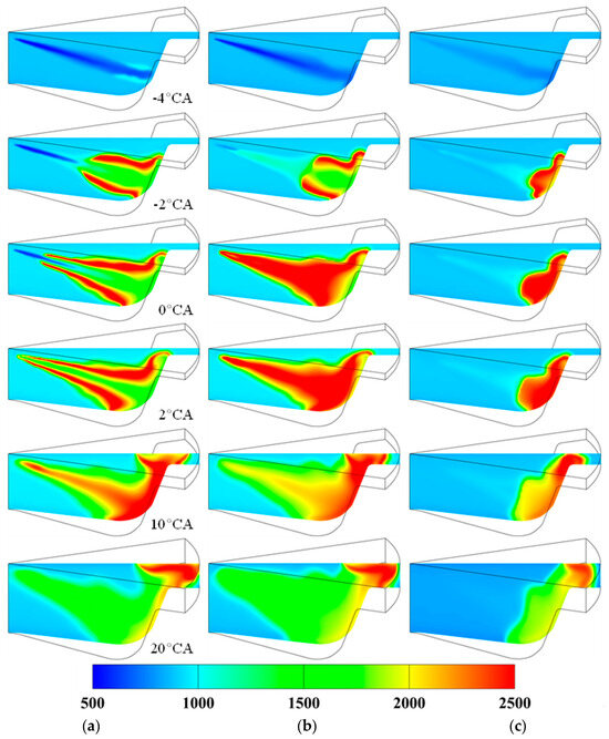
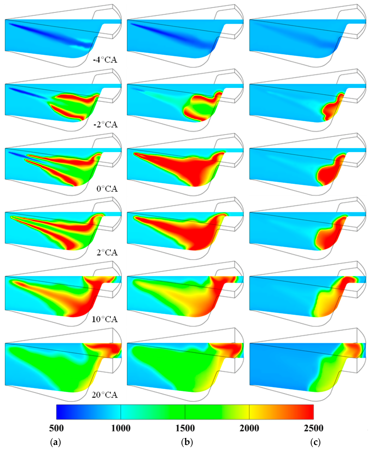
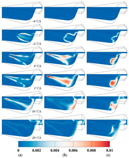
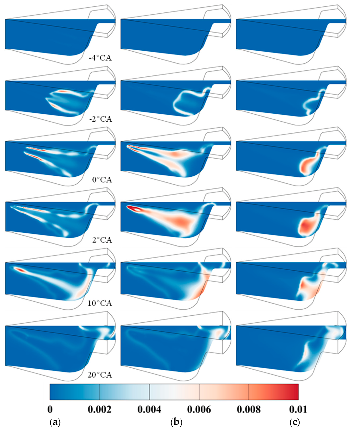
To further understand and analyze the ignition and combustion processes of ammonia/diesel dual fuel, this study compares the temperature distribution under different ammonia replacement ratios, as shown in Figure 13. The results indicate that the ignition of the diesel spray first occurs at the tip of the spray, after which the flame propagates upward along the diesel spray and spreads to unburned regions in the combustion chamber. When the ammonia replacement ratio increases to 70%, the ignition timing of diesel is significantly delayed. However, due to the accumulation of diesel injection during the ignition delay period, the combustion intensity becomes more violent. Additionally, the higher concentration of premixed ammonia enhances the flame temperature of ammonia combustion. Under the same scale, the combustion zone at a 70% ammonia replacement ratio exhibits a larger high-temperature distribution area. When the ammonia replacement ratio rises to 90%, the ignition timing of diesel is further delayed, primarily due to the significant reduction in in-cylinder oxygen concentration. In this case, the ignition points of diesel appear at the edge of the combustion chamber, where prolonged mixing with air provides favorable ignition conditions. Figure 13 also illustrates the NOx distribution under different ammonia replacement ratios. Since NOx formation requires high-temperature and oxygen-rich conditions, its spatial distribution aligns closely with the high-temperature zones.
In addition to the 100% load condition, we also analyzed the temperature field distribution and NOx distribution characteristics under the 50% load condition, as shown in Figure 15 and Figure 16. Figure 15 reveals a noticeable decrease in in-cylinder temperature at 50% load, with the area of high-temperature zones exceeding 2000 K significantly reduced compared to the 100% load case. Furthermore, the flame propagation speed after ammonia ignition decreases markedly under 50% load. Unlike the 100% load scenario, increasing the ammonia replacement ratio at 50% load does not cause severe delays in diesel ignition timing. When the ammonia replacement ratio rises to 90%, diesel can still ignite rapidly; however, ammonia combustion proceeds very slowly, and the high-temperature flame struggles to propagate to surrounding unburned regions after ignition. This is primarily due to the reduced diesel pilot quantity, which results in an insufficient high-temperature flame area generated by diesel combustion, leading to inefficient ammonia ignition. Figure 16 demonstrates that NOx formation at 50% load remains concentrated in high-temperature zones. This characteristic results in relatively lower NOx production compared to the 100% load condition, as both the size of high-temperature regions and combustion zone temperatures are reduced under 50% load.
Figure 15.
Temperature distribution under different AER (50% load). (a) AER = 50% (b) AER = 70% (c) AER = 90%.
Figure 16.
NOx distribution under different AER (50% load). (a) AER = 50% (b) AER = 70% (c) AER = 90%.
3.2. Impact of High Compression Ratio on AER
Based on the analysis of combustion characteristics under different AER, it is observed that when the AER increases to 90%, both combustion efficiency and thermal efficiency decrease significantly. This is primarily caused by the insufficient pilot diesel quantity under high replacement ratio conditions. Specifically, the combustion efficiency drops to approximately 70% under the 100% load condition and below 30% under the 50% load condition. This indicates that elevated ammonia replacement ratios have a greater adverse impact on combustion performance at medium and low loads. At 50% load, both combustion efficiency and indicated thermal efficiency exhibit a substantial reduction under the 90% ammonia replacement ratio. This is attributed to the lean ammonia-premixed mixture at 50% load, where the ammonia-premixed mixture equivalence ratio under a 90% ammonia replacement ratio is only 0.383. Combined with the extremely limited pilot diesel quantity, these factors lead to severe combustion deterioration. Therefore, this section provides a detailed analysis of the influence of equivalence ratio to investigate how the premixed equivalence ratio of ammonia in the intake affects combustion and emissions. The goal is to identify the optimal equivalence ratio range for achieving efficient combustion, offering theoretical foundations and references for the organization and optimization of ammonia/diesel dual-fuel combustion.
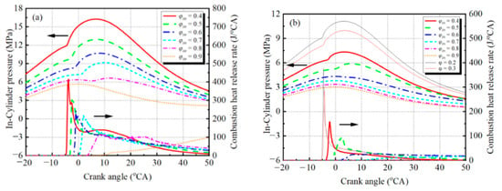
Under the 90% ammonia replacement ratio, analyses were conducted for different ammonia premixed equivalence ratios at both 50% and 100% load conditions. During calculations, the total fuel injection quantity remained constant across all cases, with equal amounts of diesel and ammonia fuel injected per cycle into the cylinder. The ammonia premixed equivalence ratio was varied by adjusting the intake air mass (i.e., the intake pressure), while the trapped volume, the compression ratio, and the total fuel energy per cycle remained unchanged. It should be noted that, since the air quantity was changed, the trapped pressure, temperature, and ignition conditions were affected simultaneously; this coupled effect is inherent to equivalence-ratio sweeps at a fixed fuel quantity and is reflected in the results discussed below. Figure 17 shows the calculated cylinder pressure and heat release rate under varying equivalence ratios. As seen in Figure 17, at low equivalence ratios, the peak heat release rate of diesel combustion is higher due to the availability of sufficient oxygen in the cylinder. However, the lean ammonia–air mixture results in low ammonia combustion efficiency. As the ammonia–air equivalence ratio increases, the peak of the heat release rate curve gradually diminishes, driven by weakened diesel combustion. At 100% load, combustion deteriorates severely when the intake equivalence ratio increases to 0.8, and misfire occurs at 0.9 (i.e., λ = 1.11). At 50% load, combustion deteriorates significantly when the intake equivalence ratio reaches 0.6, and misfire arises at 0.7 (i.e., λ = 1.43) or higher. This is attributed to low in-cylinder oxygen concentration, which hinders diesel ignition and degrades combustion performance. Particularly at 50% load, the further reduction in pilot diesel quantity exacerbates ammonia ignition challenges, leading to a higher likelihood of combustion deterioration and misfire.
Figure 17.
In-cylinder pressure and combustion heat release rate under different intake equivalence ratios. (a) 100% load; (b) 50% load.
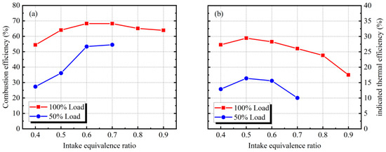
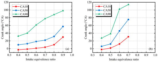
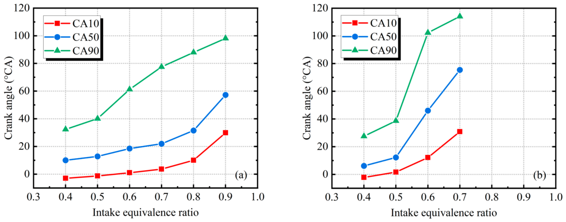
Figure 18 shows the combustion efficiency and indicated thermal efficiency under different equivalence ratios. At 100% load, combustion efficiency initially increases and then decreases with rising equivalence ratio, peaking between 0.6 and 0.7 equivalence ratio, while at 50% load, it peaks at 0.7 equivalence ratio but misfire occurs with further increases. The indicated thermal efficiency follows a trend of first increasing and then decreasing with equivalence ratio, reaching maximum values at 0.5 equivalence ratio for both 100% and 50% loads. The results suggest that achieving higher thermal efficiency requires organizing lean ammonia–air mixtures, but the equivalence ratio should not be excessively low. Based on this study’s calculations, maintaining the intake premixed equivalence ratio around 0.5 proves optimal for ammonia/diesel dual-fuel engines to attain higher thermal efficiency. The equivalence ratio significantly impacts combustion characteristics, as shown in Figure 19. Increasing the equivalence ratio markedly delays CA10, CA50, and CA90. When the equivalence ratio rises from 0.4 to 0.5, the combustion duration (CA10-CA90) lengthens slightly, but further increases cause substantial extension of combustion duration. This indicates that ammonia premixed equivalence ratios exceeding 0.5 adversely affect the combustion characteristics of ammonia/diesel dual-fuel engines.
Figure 18.
Combustion efficiency and indicated thermal efficiency under different intake equivalence ratios. (a) 100% load; (b) 50% load.
Figure 19.
CA10, CA50, and CA90 under different intake equivalence ratios (100% load and 50% load). (a) 100% load; (b) 50% load.
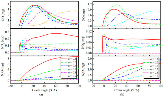
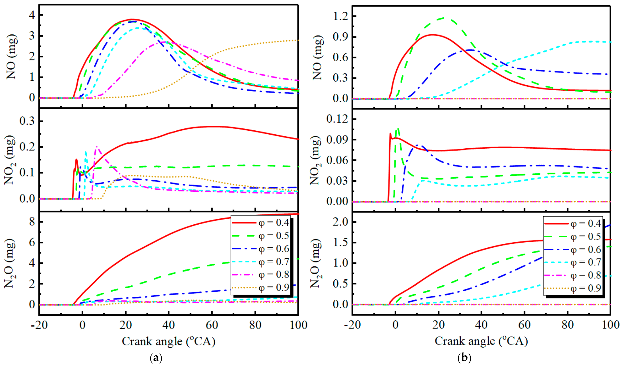
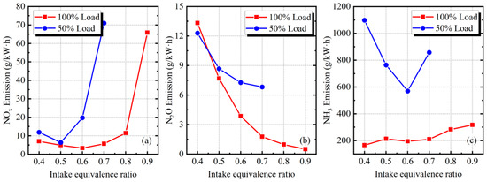
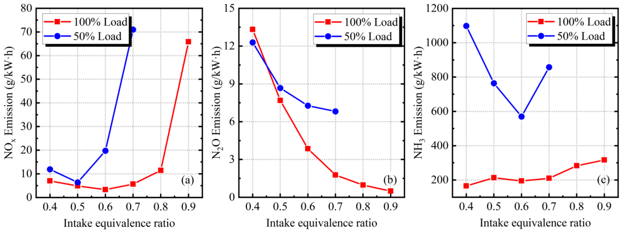
Figure 20 shows the variation curves of NO, NO2, and N2O formation quantities in the cylinder under different equivalence ratios. The equivalence ratio significantly affects nitrogen oxide formation. At 100% load, the peak NO formation gradually decreases as the equivalence ratio increases, but the final formation exhibits different patterns because NO formation typically declines after reaching its peak. When the equivalence ratio increases to 0.9, misfire occurs in the cylinder, causing NO formation to no longer follow the initial rise-then-fall pattern but instead show a gradual increase. This is mainly due to misfire hindering NH3 oxidation reactions that generate NHi radicals capable of reducing NO. NO2 formation displays more complex patterns, with higher NO2 production under low equivalence ratios and significant reduction as the equivalence ratio rises. N2O formation continuously increases during combustion but decreases with higher equivalence ratios. Nitrogen oxide formation patterns at 50% load are generally consistent with those at 100% load. Based on calculations, we evaluated NOx emissions, N2O emissions, and unburned NH3 emissions under different equivalence ratios, as shown in Figure 21. NOx emissions first decrease and then increase with rising equivalence ratios, while N2O emissions steadily decrease. Comparing emissions at 50% and 100% loads reveals higher NOx, N2O, and unburned NH3 emissions at 50% load, indicating poorer emission performance under medium-low loads.
Figure 20.
Variation patterns of NO, NO2, and N2O formation within the cylinder under different intake equivalence ratios. (a) 100% load; (b) 50% load.
Figure 21.
NOx emissions, N2O emissions, and unburned NH3 emissions under different intake equivalence ratio conditions. (a) NOx. (b) N2O. (c) NH3.
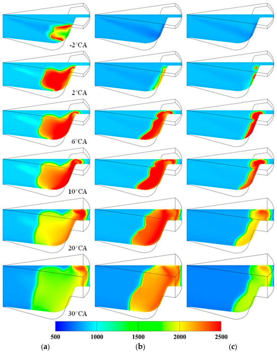
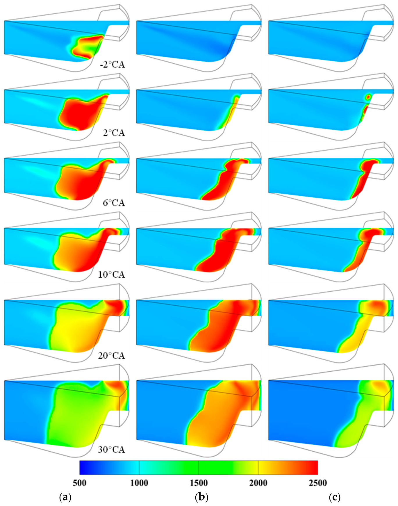
Figure 22 and Figure 23 show the temperature distribution and NOx distribution under different equivalence ratio conditions. As can be seen from Figure 22, the increase in the premixed ammonia equivalence ratio significantly hinders the ignition of diesel, causing the ignition timing of diesel to be delayed and the ignition area to shrink substantially. At an equivalence ratio of 0.5, a large high-temperature ignition zone is generated after diesel ignition, while at an equivalence ratio of 0.7, the high-temperature zone produced by diesel ignition is very small. This is mainly due to the reduced oxygen concentration in the cylinder under high premixed equivalence ratio conditions, making it more difficult to form a combustible mixture after diesel is injected into the cylinder. The significant reduction in the combustible mixture formed by the mixing of diesel and in-cylinder air leads to a smaller high-temperature zone during ignition. At 50% load, compared to 100% load, the ignition timing and high-temperature ignition area of diesel are also significantly delayed and reduced, primarily due to the decrease in diesel injection quantity. The reduced amount of pilot diesel results in less combustible mixture formed by the mixing of diesel and air. The NOx distribution characteristics shown in Figure 23 indicate that NOx generation is mainly influenced by the in-cylinder temperature distribution. As the equivalence ratio increases, the reduction in high-temperature zones leads to decreased NOx generation and a smaller NOx distribution area. However, when the equivalence ratio further increases, the significant rise in NOx emissions is primarily caused by combustion deterioration and the substantial decrease in output power, resulting in higher normalized NOx emissions.
Figure 22.
Temperature distribution under different intake equivalence ratio conditions. (a) 100% Load, φin = 0.5 (b) 100% load, φin = 0.7 (c) 50% load, φin = 0.5.
Figure 23.
NOx distribution under different intake equivalence ratio conditions. (a) 100% load, φin = 0.5 (b) 100% load, φin = 0.7 (c) 50% load, φin = 0.5.
4. Conclusions
This study developed and validated a numerical model of a marine ammonia/diesel dual-fuel engine based on the MAN L23/30H four-stroke engine, with simulated in-cylinder pressure agreeing with experimental data within 2%. Dual-fuel combustion proceeds through diesel pilot auto-ignition followed by flame propagation of the premixed ammonia–air charge. Increasing the ammonia substitution ratio extends the ignition delay and retards the combustion phase; peak cylinder pressure first increases and then decreases with rising AER.
- (1)
- At 100% load, raising AER from 50% to 70% enhances both combustion efficiency and indicated thermal efficiency, whereas at 90% AER and particularly at 50% load, the greatly reduced pilot diesel quantity leads to severe combustion deterioration, with combustion efficiency dropping below 30% at 50% load. The ammonia premixed equivalence ratio is decisive for combustion organization: an equivalence ratio of approximately 0.5 yields the highest thermal efficiency, while higher ratios markedly delay CA10, CA50, and CA90 and eventually cause misfire at 0.9 under 100% load and at 0.7 under 50% load.
- (2)
- NO and NO2 formation exhibit non-monotonic trends owing to the reduction effects of ammonia-derived radicals. N2O, as a characteristic product of ammonia combustion, forms preferentially at lower temperatures and is therefore more pronounced under 50% load, and normalized NOx and unburned NH3 emissions increase substantially at 90% AER, indicating poorer emission performance under medium-low loads. Maintaining the intake ammonia premixed equivalence ratio around 0.5 and avoiding excessively high substitution ratios, particularly under partial loads, are recommended for efficient and clean ammonia/diesel dual-fuel combustion in marine engines. In addition, considering that unburned ammonia is toxic and that its emission must be minimized, combustion efficiencies below 95% are not acceptable in practical applications; the substitution ratio should therefore be limited to a range in which the combustion efficiency remains sufficiently high, and the pilot diesel quantity and injection strategy should be further optimized.
Author Contributions
Z.W.: Writing—original draft, Investigation. J.Z. (Jie Zhu): Writing—review and editing, Software, Data curation. X.L.: Writing—review and editing. N.L.: Methodology, Investigation. J.Z. (Jingjun Zhong): Methodology, Investigation. All authors have read and agreed to the published version of the manuscript.
Funding
Supported by the National Key R&D program of China (Grant No. 2022YFB4300701, December 2022–November 2026) and the National Key R&D program of China (Grant No. 2022YFB4300704, December 2022–November 2026).
Institutional Review Board Statement
Not applicable.
Informed Consent Statement
Informed consent was obtained from all subjects involved in the study.
Data Availability Statement
The original contributions presented in this study are included in the article. Further inquiries can be directed to the corresponding author.
Conflicts of Interest
The authors declare no conflicts of interest.
References
- International Maritime Organization. 2023 IMO Strategy on Reduction of GHG Emissions from Ships. Available online: https://wwwcdn.imo.org/localresources/en/KnowledgeCentre/IndexofIMOResolutions/MEPCDocuments/MEPC.377(80).pdf (accessed on 1 September 2026).
- International Energy Agency. Global Energy Review: CO2 Emissions in 2020. Available online: https://www.iea.org/articles/global-energy-review-co2-emissions-in-2020 (accessed on 15 October 2026).
- Kurien, C.; Mittal, M. Review on the production and utilization of green ammonia as an alternate fuel in dual-fuel compression ignition engines. Energy Convers. Manag. 2022, 251, 114990. [Google Scholar] [CrossRef] [Scilit]
- Meng, X.; Zhang, M.; Zhao, C.; Tian, H.; Tian, J.; Long, W.; Bi, M. Study of combustion and NO chemical reaction mechanism in ammonia blended with DME. Fuel 2022, 319, 123832. [Google Scholar] [CrossRef] [Scilit]
- Nie, X.; Bi, Y.; Shen, L.; Lei, J.; Wan, M.; Wang, Z.; Liu, S.; Huang, F. Combustion and emission characteristics of ammonia-diesel dual fuel engine at different altitudes. Fuel 2024, 371, 132072. [Google Scholar] [CrossRef] [Scilit]
- Wang, Y.; Zhou, X.; Liu, L. Feasibility Study of Hydrogen Jet Flame Ignition of Ammonia Fuel in Marine Low Speed Engine. Int. J. Hydrogen Energy 2023, 48, 327–336. [Google Scholar] [CrossRef] [Scilit]
- D’Antuono, G.; Lanni, D.; Galloni, E.; Fontana, G. Numerical Analysis of the Combustion Process in a Pre-Chamber Marine Engine Fueled with Ammonia-Hydrogen Mixtures; SAE Technical Paper 2025-24-0021; SAE International: Warrendale, PA, USA, 2025. [Google Scholar]
- Wu, Y.; Hu, J.; Lin, Y.; Chen, P.; Chen, G.; Wang, Z. Experimental study of ammonia energy ratio on combustion and emissions from ammonia-gasoline dual-fuel engine at various load conditions. J. Energy Inst. 2024, 117, 101868. [Google Scholar] [CrossRef] [Scilit]
- Chen, Y.; Zhang, J.; Zhang, Z.; Zhang, B.; Hu, J.; Zhong, W.; Ye, Y. Optimization of ammonia energy ratio and injection timing for ammonia diesel dual-fuel engines based on RSM. Fuel 2025, 381, 133660. [Google Scholar] [CrossRef] [Scilit]
- Jin, Z.; Mi, S.; Zhou, D.; Qian, Y.; Lu, X. The characteristics analysis and feasible improvement strategy evaluation for ammonia-diesel dual-fuel engine under heavy load and high ammonia ratio conditions. Fuel 2025, 383, 133911. [Google Scholar] [CrossRef] [Scilit]
- Wei, Y.M.; Chen, K.; Kang, J.N.; Chen, W.; Wang, X.-Y.; Zhang, X. Policy and management of carbon peaking and carbon neutrality: A literature review. Engineering 2022, 14, 52–63. [Google Scholar] [CrossRef] [Scilit]
- Li, J.; Zhang, R.; Pan, J.; Wei, H.; Shu, G.; Chen, L. Ammonia and hydrogen blending effects on combustion stabilities in optical SI engines. Energy Convers. Manag. 2023, 280, 116827. [Google Scholar] [CrossRef] [Scilit]
- Zhao, W.; Zhang, Y.; Huang, G.; He, Z.; Qian, Y.; Lu, X. Experimental investigation on combustion and emission characteristics of butanol/biodiesel under blend fuel mode, dual fuel RCCI and ICCI modes. Fuel 2021, 305, 121590. [Google Scholar] [CrossRef] [Scilit]
- Li, Z.; Qian, Y.; Huang, G.; Zhao, W.; Zhang, Y.; Lu, X. Gasoline-diesel dual fuel intelligent charge compression ignition (ICCI) combustion: Conceptual model and comparison with other advanced combustion modes. Sci. China Technol. Sci. 2021, 64, 719–728. [Google Scholar] [CrossRef] [Scilit]
- Liu, X.; Kokjohn, S.; Wang, H.; Yao, M. A comparative numerical investigation of reactivity controlled compression ignition combustion using large eddy simulation and reynolds-averaged navier-stokes approaches. Fuel 2022, 257, 116023. [Google Scholar]
- Shi, X.R.; Xiong, Q.; Pan, C.Y.; Liu, L.; Fu, S.Y.; Zhao, J.H. Effect of ammonia energy fraction and injection strategy on the combustion and emission of dual-fuel low-speed engine. J. Int. Combust. Eng. 2024, 42, 489–498. [Google Scholar]
- Xu, L.; Chang, Y.; Treacy, M.; Zhou, Y.; Jia, M.; Bai, X.S. A Skeletal Chemical Kinetic Mechanism for Ammonia/n-Heptane Combustion. Fuel 2023, 331, 125830. [Google Scholar] [CrossRef] [Scilit]
- Maroteaux, F.; Saad, C. Combined mean value engine model and crank angle resolved in-cylinder modeling with NOx emissions model for real-time diesel engine simulations at high engine speed. Energy 2015, 88, 515–527. [Google Scholar] [CrossRef] [Scilit]
- Li, Z.; Wang, Y.; Yin, Z.; Gao, Z.; Wang, Y.; Zhen, X. Parametric study of a single-channel diesel/methanol dual-fuel injector on a diesel engine fueled with directly injected methanol and pilot diesel. Fuel 2021, 302, 121156. [Google Scholar] [CrossRef] [Scilit]
- Han, Z.; Reitz, R.D. Turbulence modeling of internal combustion engines using RNG k-ε models. Combust. Sci. Technol. 1995, 106, 267–295. [Google Scholar] [CrossRef] [Scilit]
- Dec, J.E.; Reltz, R.D. Comparisons of diesel spray liquid penetration and vapor fuel distributions with in-cylinder optical measurements. J. Eng. Gas. Turb. Power 2000, 122, 588–595. [Google Scholar] [CrossRef] [Scilit]
- Schmidt, D.P.; Rutland, C.J. A new droplet collision algorithm. J. Comput. Phys. 2000, 164, 62–80. [Google Scholar] [CrossRef] [Scilit]
- Han, Z.; Reitz, R.D. A temperature wall function formulation for variable-density turbulent flows with application to engine convective heat transfer modeling. Int. J. Heat Mass Tran. 1997, 40, 613–625. [Google Scholar] [CrossRef] [Scilit]
- Senecal, P.K.; Pomraning, E.; Richards, K.J.; Briggs, T.E.; Choi, C.Y.; McDavid, R.M.; Patterson, M.A. Multi-dimensional modeling of direct-injection diesel spray liquid length and flame lift-off length using cfd and parallel detailed chemistry. J. Engines 2003, 112, 1331–1351. [Google Scholar]
- O’Rourke, P.J.; Amsden, A.A. A spray/wall interaction submodel for the KIVA-3 wall film model. J. Engines 2000, 109, 281–298. [Google Scholar]
- Zhang, Y.; Xu, L.; Zhu, Y.; Xu, S.; Bai, X.-S. Numerical study on liquid ammonia direct injection spray characteristics under engine-relevant conditions. Appl. Energy 2023, 334, 120680. [Google Scholar] [CrossRef] [Scilit]
- Zhu, J.; Zhou, D.; Yang, W.; Qian, Y.; Mao, Y.; Lu, X. Investigation on the potential of using carbon-free ammonia in large two-stroke marine engines by dual-fuel combustion strategy. Energy 2023, 263, 125748. [Google Scholar] [CrossRef] [Scilit]
- Zhang, J.; Chen, D.; Lai, S.; Li, J.; Huang, H.; Kobayashi, N. Numerical simulation and spray model development of liquid ammonia injection under diesel-engine conditions. Energy 2024, 294, 130833. [Google Scholar] [CrossRef] [Scilit]
- Valera-Medina, A.; Xiao, H.; Owen-Jones, M.; David, W.I.F.; Bowen, P.J. Ammonia for Power. Prog. Energy Combust. Sci. 2018, 69, 63–102. [Google Scholar] [CrossRef] [Scilit]

Disclaimer/Publisher’s Note: The statements, opinions and data contained in all publications are solely those of the individual author(s) and contributor(s) and not of MDPI and/or the editor(s). MDPI and/or the editor(s) disclaim responsibility for any injury to people or property resulting from any ideas, methods, instructions or products referred to in the content. |
© 2026 by the authors. Licensee MDPI, Basel, Switzerland. This article is an open access article distributed under the terms and conditions of the Creative Commons Attribution (CC BY) license.