


Abstract
To address the challenge in real-time communication mooring systems where clock synchronization and data transmission are difficult to achieve simultaneously over a single jacketed steel cable loop, this paper develops a dual-carrier inductively coupled communication (ICC) scheme based on the design concept of frequency division multiplexing (FDM). Two carrier signals with distinct frequencies and modulation schemes are loaded in parallel onto the same cable loop, using binary differential phase-shift keying (2DPSK) to carry minute-level data communication and binary phase-shift keying (2PSK) to carry microsecond-level clock synchronization broadcasts. To resolve inter-carrier crosstalk and channel attenuation, a single-stage multiple feedback (MFB) narrow bandpass filter and a three-stage analog front-end consisting of “passive high-impedance filtering, differential-to-single-ended conversion, and multistage active high-gain amplification” are designed in hardware, achieving efficient separation of hybrid signals and suppression of noise. In software, a combined demodulation architecture based on digital delay differential and zero-crossing decision, along with a digital Costas loop, is constructed to accomplish data demodulation and high-precision pulse-per-second (PPS) clock recovery. Laboratory and 300 m nearshore sea trial results demonstrate that the system achieves a packet reception ratio of over 89.60%, an error-free packet delivery ratio exceeding 83.24% with a bit error ratio below 0.22%, and maintains a clock synchronization error within 200 µs.
1. Introduction
Real-time communication moorings serve as crucial platforms for in situ deep-sea observation, enabling long-term, continuous acquisition and real-time retrieval of profile data [1,2,3]. However, in scenarios requiring synchronized observation of hydrological environments and acoustic parameters, the need for high-precision clock synchronization among hydrophone arrays—alongside real-time data uplink and command downlink during long-term deployments—places stringent demands on the underwater mooring communication link [4,5]. Existing real-time communication moorings predominantly operate in half-duplex mode. Constrained by the single-loop steel wire rope topology and power limitations, these links struggle to balance multi-node clock synchronization and data communication under resource-constrained condition [6].
To address underwater data transmission challenges, early mooring systems relied heavily on multi-core watertight cables, which suffered from engineering flaws including prone-to-failure wet-mate connectors, high maintenance costs, and limited long-term reliability. Optical communications are restricted in range by seawater absorption and scattering [7,8], whereas underwater acoustic communications are constrained by channel bandwidth, multipath propagation, and ambient noise—making them ill-suited for multi-node synchronous acquisition scenarios [9,10]. By contrast, ICC utilizes a single steel wire rope or a seawater return loop to accomplish contactless transmission via electromagnetic induction, eliminating the reliability risks associated with direct electrical connections while providing robust anti-interference capability. This makes ICC an ideal candidate for deep-sea distributed multi-node communication networks [11,12]. Nevertheless, breaking through the single-carrier half-duplex limitation of conventional ICC systems to enable concurrent data transmission and clock synchronization remains a critical challenge to be resolved.
Initial research on ICC primarily focused on concept validation and hardware system integration. In 1965, Brown proposed the concept of underwater data transmission using magnetic ring coupling. By the 1990s, Fougere et al. at the Woods Hole Oceanographic Institution developed practical inductively coupled modems, established an equivalent circuit model based on seawater returns, and successfully deployed them in field systems such as the ATLAS buoy and the Bermuda Test Be [12,13]. Regarding modulation and demodulation methods, researchers such as Stojanovic and Kisseleff conducted studies focused on coherent demodulation, phase tracking, and modulation strategy optimization, laying a solid foundation for signal processing and modulation scheme selection in subsequent ICC links [14,15]. Entering the 21st century, commercial vendors such as Sea-Bird Scientific and RBR pushed ICC toward standardization and commercialization. Sea-Bird systems support transmission distances up to 6000 m with up to 100 attached nodes at data rates reaching 4800 bps; meanwhile, RBR systems employ a distributed architecture supporting intelligent addressing and packetized communication to achieve low-power asynchronous transmission across ranges up to 4000 m.
As ICC hardware platforms matured, academic research increasingly pivoted toward advanced channel modeling and modulation optimization to enhance transmission reliability in complex underwater environments. Early on, researchers such as Stojanovic and Kisseleff conducted pioneering studies focused on coherent demodulation, phase tracking, and modulation strategy optimization. Building upon these foundational signal processing frameworks, substantial progress has been made in overcoming specific channel impairments. Li et al. conducted research on inductively coupled transmission over oceanographic CTD single-core cables, achieving stable co-cable transmission and low bit-error-rate (BER) recovery of both power and high-rate digital measurement signals over a single steel cable loop [16]. Qiu et al. designed a virtual instrument-based ICC channel analysis system to evaluate the relationship between carrier frequency and system robustness [17]. Furthermore, targeting the composite channels formed by seawater media and mooring chain loops, Zheng et al. proposed a multi-node adaptive orthogonal frequency division multiplexing inductively coupled transmission technology, systematically evaluating transmission characteristics across varying node locations and channel parameters while achieving multi-node adaptive modulation based on signal-to-noise ratio (SNR) feedback [18].
In summary, existing domestic and international research has established a solid foundation in ICC channel modeling, modulation optimization, and engineering applications [19]. However, the majority of mainstream commercial and in situ marine subsurface buoy systems currently prioritize single-carrier half-duplex data transmission, lacking coordinated optimization at the physical layer for high-precision time reference broadcasting. In multi-node moored observations, there is a high demand for temporal concurrency between hydrological data exchange and acoustic time reference distribution—a requirement that traditional single-carrier half-duplex systems are unable to fulfill. Relying on time-division multiplexing compromises temporal efficiency, rendering it incapable of simultaneously satisfying minute-level data exchange and microsecond-level clock synchronization. Therefore, breaking through the half-duplex limitation while preserving the low-power and high-reliability advantages of ICC remains the key bottleneck in enabling parallel processing for data transmission and clock synchronization.
To address the aforementioned challenges, this paper proposes a dual-carrier inductively coupled communication scheme based on FDM. It focuses on the physical model construction and experimental validation of parallel transmission for data acquisition and time reference synchronization in seawater channels. Specifically, the inductive coupling transmission mechanism and signal modulation techniques are first quantitatively analyzed to determine the 2PSK and 2DPSK modulation schemes along with their corresponding carrier frequencies. Subsequently, to mitigate the signal overlap interference induced by dual-carrier loop transmission, a waveform restoration circuit centered on a narrowband pass filter is designed to isolate and recover the distinct carrier signals. Finally, coherent demodulation software built around a Costas loop is developed to process both 2PSK and 2DPSK signals. Through numerical simulations and nearshore field tests, the proof of concept and feasibility evaluation of this dual-carrier link under typical operating conditions were completed, providing an engineering reference for the design of real-time communication subsurface buoy systems aimed at synchronous hydrological and acoustic field observations.
2. Analysis of Inductively Coupled Model and Design of Dual-Carrier Architecture
2.1. Analysis of Equivalent Circuit Model
ICC is a non-contact signal transmission technology based on the principle of electromagnetic induction [20], which achieves reliable information transfer by utilizing an alternating magnetic field to induce an electromotive force at the receiving terminal. The structural model and communication principles of ICC are similar to those of a transformer. At the transmitter, the output terminal is connected to a multi-turn winding coil that passes through a magnetic ring, forming the primary side of the transformer. Similarly, at the receiver, a multi-turn winding coil passes through a magnetic ring to serve as the secondary side. When the magnetic rings of both the transmitter and receiver are threaded through a closed-loop circuit formed by a single jacketed steel cable and seawater, a complete inductively coupled communication link is established [21,22,23].
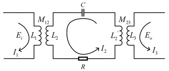
To quantitatively analyze the signal transmission characteristics of the inductively coupled system, the cascaded system—comprising two-stage magnetic cores, a single plastic-coated steel wire rope, and a seawater return loop—is modeled as an equivalent closed circuit consisting of a “transmitting step-down transformer, channel transmission loop, and receiving step-up transformer,” as illustrated in Figure 1. The coupling magnetic core and winding coil of the master node at the transmitting end are modeled as a step-down transformer with a turns ratio of N:1, converting electrical signals into magnetic field energy, the frequency characteristics of the magnetic core are shown in Table 1. Conversely, the coupling magnetic core and winding coil of the underwater slave node are modeled as a step-up transformer with a turns ratio of 1:N, restoring the magnetic field energy back into electrical signals. The single-turn closed loop formed by the plastic-coated steel wire rope and seawater acts as the core transmission channel carrying the alternating induced current.
Figure 1.
Equivalent circuit model of inductively coupled channel.
Table 1.
Magnetic-core frequency characteristics.
Based on Kirchhoff’s Voltage Law (KVL) [24,25], the loop equations for the equivalent circuit are derived as follows. Let Ei be the excitation signal at the transmitting end, Eo be the open-circuit induced electromotive force at the receiving end, L1 be the multi-turn winding inductance at the transmitting end, and L3 be the multi-turn winding inductance at the receiving end. The single-turn equivalent self-inductances excited when the single jacketed steel cable passes through the transmitting and receiving magnetic rings are denoted as L2 and L2′ respectively. Because the master and slave ends utilize magnetic ring structures of identical geometric dimensions and materials, physically, L2 = L2′. Furthermore, given an equal number of winding turns on both the transmitting and receiving sides, the self-inductances satisfy L1 = L3. The total equivalent resistance of the loop is R, and the distributed capacitance along the line between the outer sheath of the jacketed steel cable and the seawater is modeled as an equivalent series capacitance C. Additionally, considering the impact of minute gaps at the actual mating surfaces of the magnetic rings on magnetic leakage, coupling coefficients k1 and k2 (0 < k1, k2 ≤ 1) are introduced for the transmitting and receiving ends, respectively. Under ideal open-circuit conditions where the load impedance at the receiving end approaches infinity, the equivalent impedances and mutual inductance coefficients of each loop can be expressed as
the loop equations can be derived as follows:
By combining the above relations with the loop equation, the relationship between Vout and Vin is obtained as
Because gaps and eccentricities exist at the mating surfaces during actual magnetic core installation, which directly impact the induced electromotive force [26], a magnetic core coupling coefficient k (0 < k ≤ 1) is introduced. Furthermore, to simplify the design and reduce costs, the master and slave modules typically employ identical magnetic cores and winding turns. Consequently, L1 = L3 (since the magnetic cores and the number of winding turns are identical at both the transmitting and receiving ends, L1 and L3 cancel each other out). Furthermore, assuming symmetrical installation at both ends, the coupling coefficients are approximately equal, yielding k1 ≈ k1 ≈ k. Thus, the simplified formula can be expressed as:
As indicated by the transfer function, the magnitude of the induced electromotive force at the receiving end is positively correlated with the excitation voltage at the transmitting end, the magnetic core coupling coefficient, and the carrier frequency, while being negatively correlated with the total equivalent resistance of the loop.
2.2. Dual-Carrier Frequency Division Multiplexing Scheme
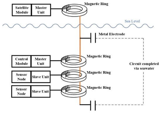
In a real-time communication mooring system, inductively coupled modules are generally categorized into master units and slave units [27]. The master unit is mounted on critical control nodes such as the mooring control capsule, while the slave units are embedded within individual sensor nodes. A single jacketed steel cable threads through the coupling magnetic rings of all nodes and forms a complete communication circuit with seawater via metal electrodes at both ends, as illustrated in Figure 2. The inductively coupled link must accommodate multiple sensor nodes to collect various ocean profile data, including hydrological environment and acoustic field information [28]. Among these, hydrological data require minute-level transmission capabilities with a relatively high communication frequency, while hydrophone arrays require intermittent clock synchronization with accuracy down to the hundred-microsecond level. Inductively coupled communication inherently operates in a half-duplex mode, yet both data transmission and clock synchronization must be accomplished simultaneously within the same communication link.
Figure 2.
Communication Link Architecture.
This paper employs a FDM architecture as the engineering approach for physical-layer channel decoupling. By configuring two independent carriers in widely separated frequency bands, telemetry data and time reference pulses are separately transmitted over a single-cable loop. This effectively resolves the physical structural limitations and communication compatibility challenges inherent in inductively coupled links. By simultaneously loading two carrier signals with different frequencies and modulation schemes into a single steel cable loop, they respectively carry the tasks of data communication and clock synchronization, thereby achieving an integrated design for data transmission and clock synchronization.
2.3. Signal Modulation and Driver Circuit Design
In accordance with the principle of FDM [18,29], this paper constructs a dual-channel parallel transmission scheme for data communication and clock synchronization over a single plastic-coated steel wire rope loop. Within this architecture, the data communication link employs 2DPSK modulation with a center frequency of 4.8 kHz, which is responsible for minute-level, high-frequency data interaction while emphasizing low-power operation of the microcontroller. Meanwhile, the clock synchronization link utilizes 2PSK modulation with a center frequency of 25.6 kHz to broadcast a high-precision, microsecond-level time reference, prioritizing high-speed signal sampling and coherent demodulation processing. To reduce hardware complexity, both modulated signals are synthesized using internal high-precision microcontroller timers to generate square-wave carriers of specific frequencies, with digital modulation realized via the logic outputs of general-purpose input/output (GPIO) pins.
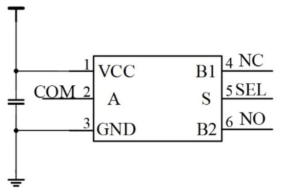
To address the signal attenuation problem caused by the high equivalent impedance of the inductively coupled channel, this paper designs a power drive circuit based on analog switch toggling. If microcontroller GPIO pins were used to drive the coil directly, the strength of the induced magnetic field would be insufficient due to constraints on output current and voltage swing—frequently leading to demodulation failure at the receiving end as a result of an excessively low induced electromotive force. As illustrated in Figure 3, the transmitter power drive circuit utilizes an analog switch IC characterized by low on-resistance and high switching speed. Its input terminals are connected to the system power supply VCC and ground GND, respectively, while its control terminal is connected to the microcontroller modulation pin. In the transmit state, the modulation signal controls the analog switch to toggle rapidly between VCC and GND, applying the supply voltage directly across the transmitting coil. This delivers a substantial instantaneous drive current that significantly boosts magnetic field strength. In the receive state, the analog switch is fixed to a low-level pass-through mode, allowing the induced electromotive force from the coil to pass lossless to the subsequent receiver circuit.
Figure 3.
Schematic of low-impedance power driver circuit.
3. Filtering and Delay-Coherent Demodulation for the 2DPSK Data Communication Link
3.1. Design of Multiple Feedback Narrow Bandpass Filter
In the dual-carrier FDM inductively coupled communication system, the electrical signal captured by the receiving magnetic core is a multi-component composite signal. The desired component is the 2DPSK data signal carried on the 4.8 kHz carrier, whereas the interference components include the 25.6 kHz 2PSK clock synchronization signal co-transmitted in the same loop, deep-sea broadband electromagnetic environment noise, higher-order harmonics induced by the steel cable skin effect and magnetic core dispersion, as well as waveform distortions caused by channel multipath effects [30]. For the 2DPSK data link employing software differential demodulation, out-of-band interference not only shifts the symbol decision threshold and causes phase jump edge identification errors—leading to an increased BER—but more critically, the 25.6 kHz 2PSK signal co-exists in the same loop with an amplitude of comparable magnitude. Without deep suppression, it will directly disrupt the phase integrity of the 2DPSK signal and induce severe inter-frequency crosstalk [31]. Therefore, designing a highly selective filter-amplifier circuit to effectively extract the target signal and deeply suppress out-of-band interference is critical to ensuring crosstalk-free and stable operation of the dual-carrier system.
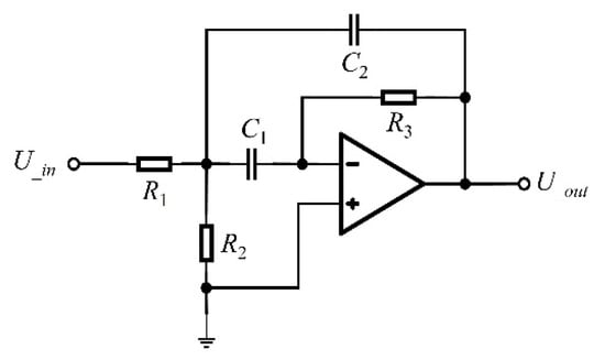
To address underwater low-power design requirements, this paper eschews the higher-power Sallen-Key high-pass/low-pass cascaded architecture and adopts a single-stage MFB structure to build the 4.8 kHz bandpass filter, with its circuit topology illustrated in Figure 4. MFB architecture achieves low-noise amplification of in-band signals while providing excellent out-of-band frequency suppression, thereby maximizing the attenuation of interference from the 25.6 kHz carrier on the 2DPSK signal [32,33]. The center frequency f0 of the filter is set to 4.8 kHz, with a passband range designed from 3.6 to 6.0 kHz, within which the gain is no less than −3 dB.
Figure 4.
Circuit topology of the bandpass filter.
Based on complex frequency domain analysis, setting the filter capacitors as C1 = C2 = C, the equations relating the MFB filter center frequency f0, passband gain Am, and quality factor Q are derived as follows:
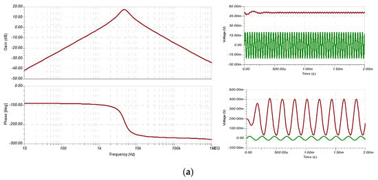
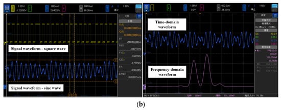
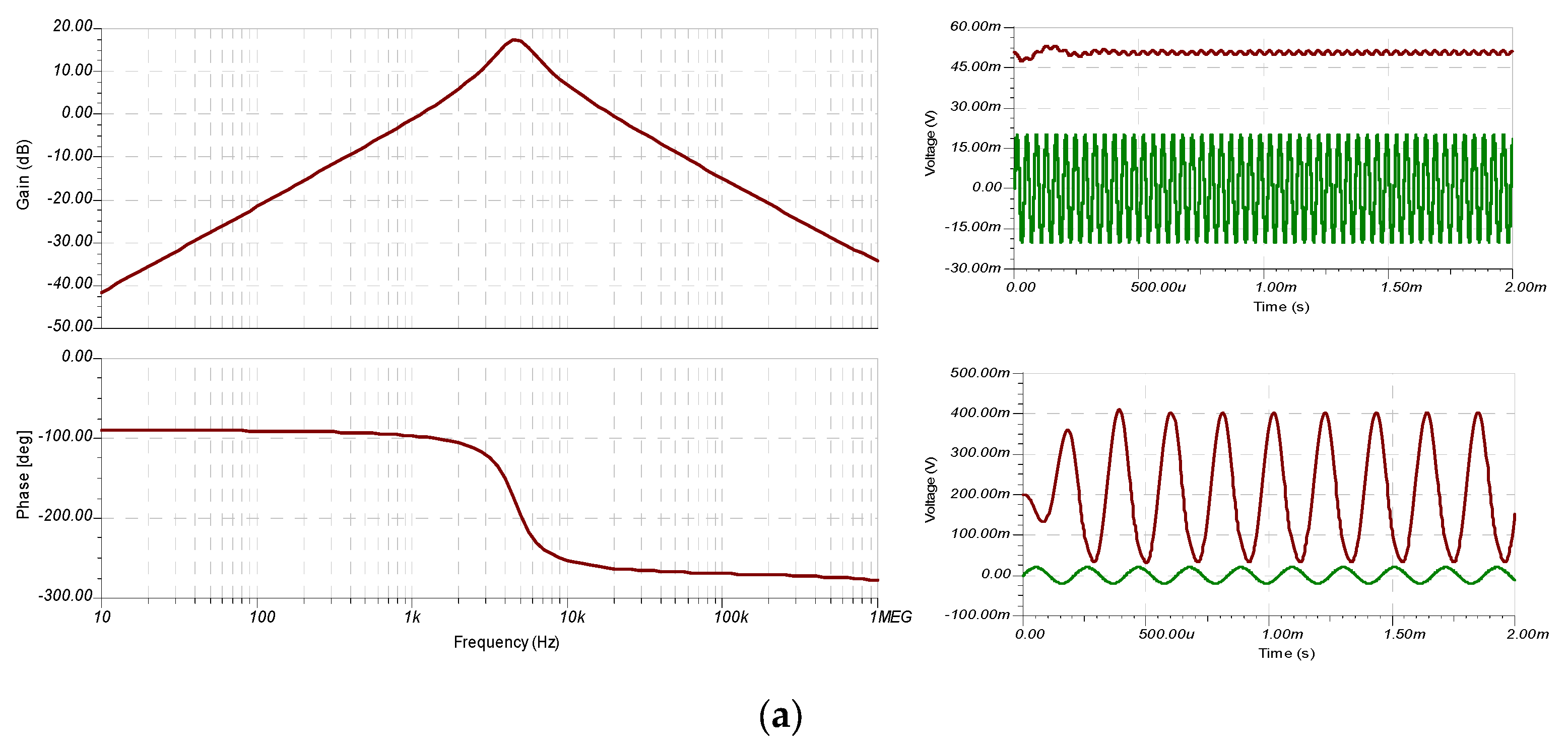
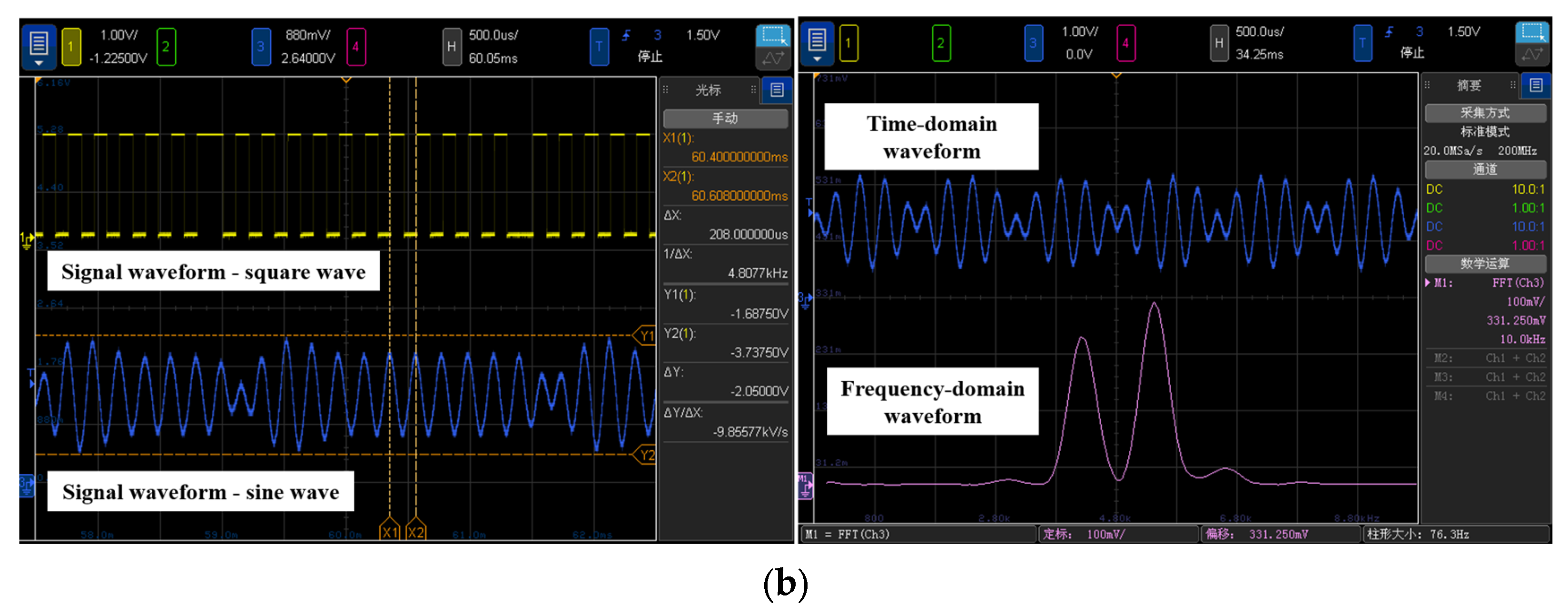
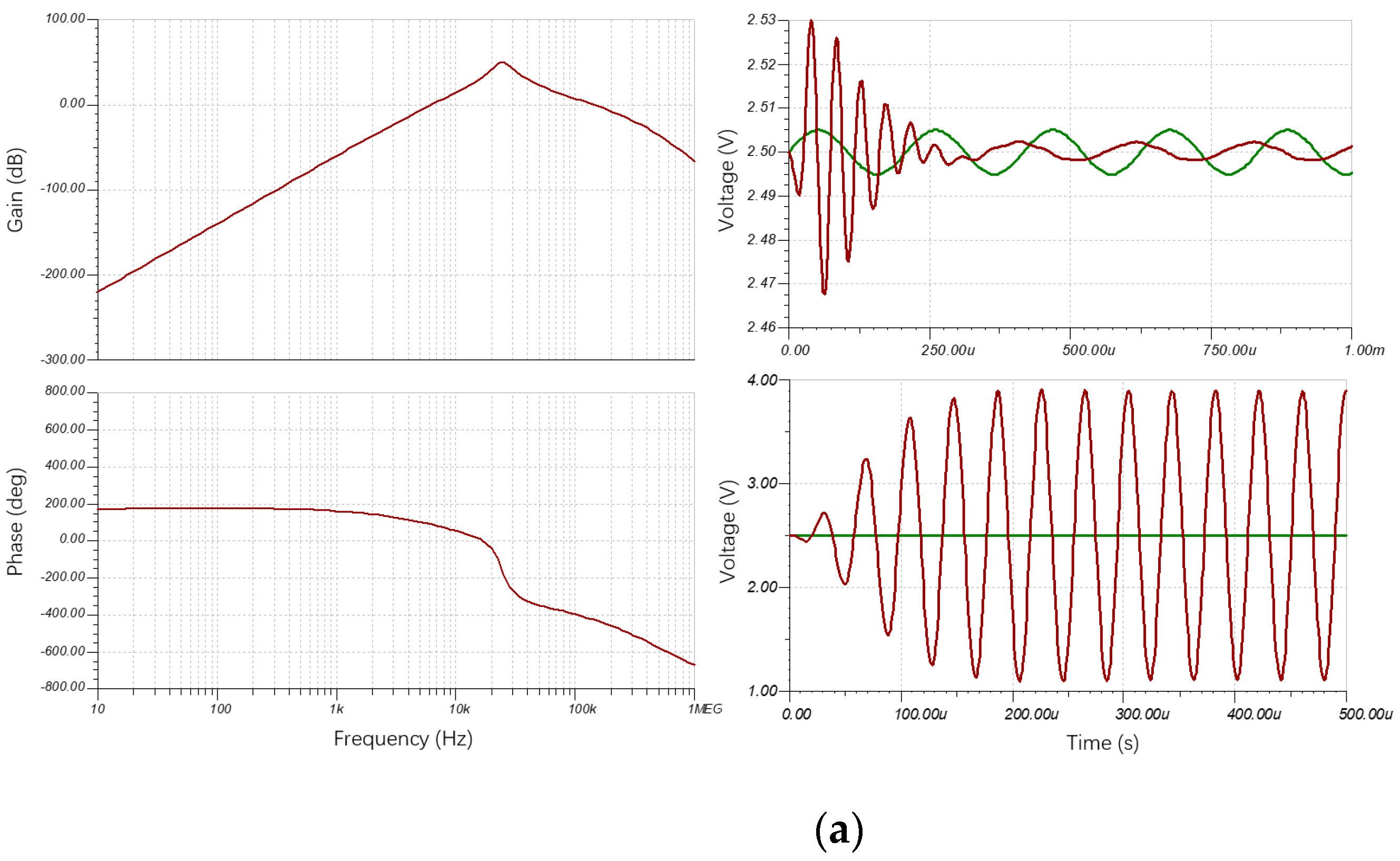
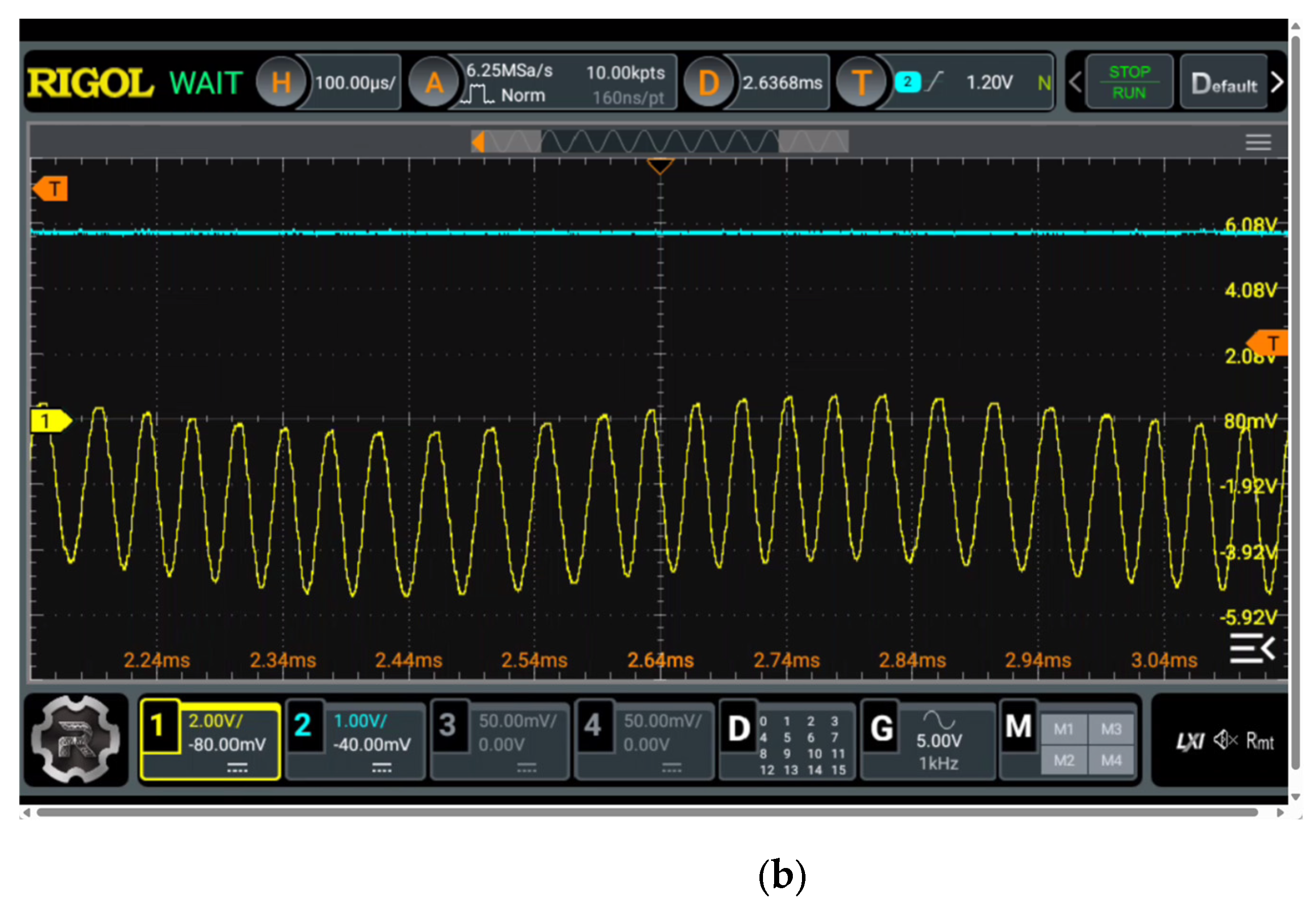
The simulated and measured amplitude–frequency response results are shown in Figure 5. The circuit achieves a passband gain of 17.5 dB at the center frequency of 4.8 kHz, with the gain exceeding 14.5 dB across the entire 3.6~6.0 kHz passband. For the 25.6 kHz 2PSK clock synchronization signal, the circuit gain drops to -2.5 dB, providing a relative peak suppression ratio of approximately 20 dB and achieving deep attenuation of the high-frequency clock signal. Concurrently, the circuit provides an attenuation exceeding 2 dB for low-frequency noise below 1 kHz and high-frequency interference above 100 kHz. Experimental waveforms (shown in Figure 5b) confirm that when a mixed front-end signal with an input amplitude of 16 mV is filtered and amplified, the 25.6 kHz interference component is attenuated to below 2 mV within 100 μs, while the target 4.8 kHz signal amplitude is boosted to 200 mV. This yields a restored signal for subsequent software demodulation, effectively realizing waveform restoration and low-noise amplification of the 2DPSK signal.
Figure 5.
Simulated and measured amplitude–frequency response results. (a) Simulation image of amplitude–frequency response of narrow bandpass filter circuit. (b) Measured waveform of narrow bandpass filter circuit.
3.2. Design of Delay Differential Demodulation Algorithm
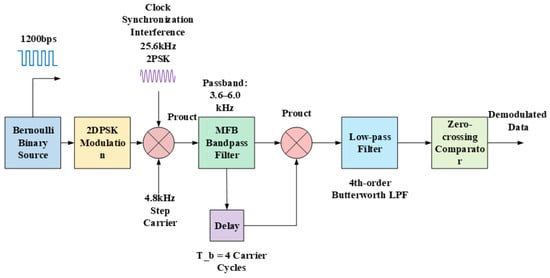
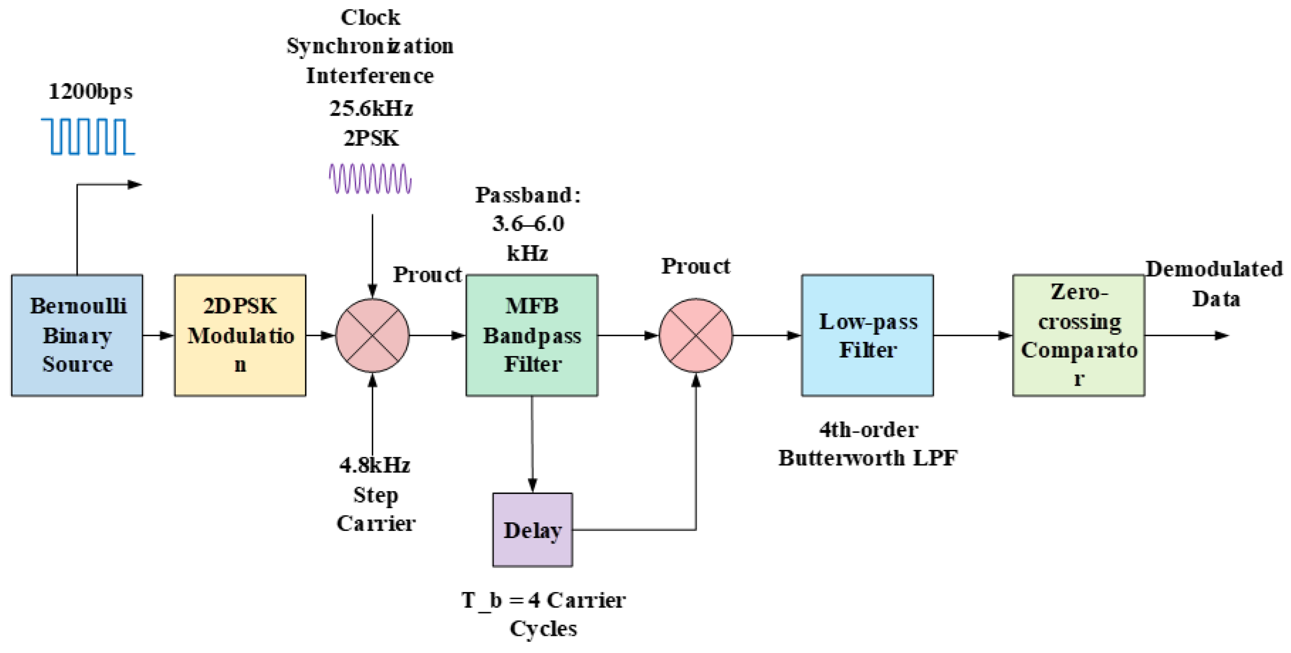
To support efficient demodulation of 2DPSK signals under resource-constrained environments—such as low-power microcontrollers—a system-level simulation model was constructed on the Simulink platform. As illustrated in Figure 6, this model encompasses two main parts: the front-end signal processing chain and the software demodulation core, achieving a complete end-to-end simulation from baseband source generation to demodulated output [34]. In the front-end processing stage, a Bernoulli binary source operating at a symbol rate of 1200 bps undergoes 2DPSK encoding and is mixed with a 4.8 kHz carrier before being corrupted by additive interference from the 25.6 kHz 2PSK clock synchronization signal co-transmitted in the same loop. The composite signal then passes through a second-order Butterworth bandpass filter with a passband of 3.6–6.0 kHz, which effectively extracts the 4.8 kHz target carrier while deeply suppressing the high-frequency clock interference. The software demodulation core is built upon a joint architecture of digital delay differential detection and zero-crossing decision. By multiplying the bandpass-filtered signal with its version delayed by one symbol period, the relative phase change between adjacent symbols is extracted. The multiplied signal is subsequently routed through a fourth-order Butterworth low-pass filter with a cutoff frequency of 4.0 kHz to eliminate high-frequency double-carrier components, and is finally passed to a zero-crossing comparator for binary symbol recovery.
Figure 6.
Block image of the system simulation model.
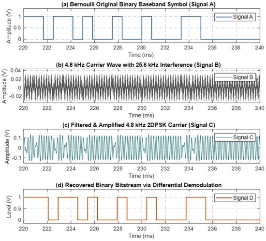
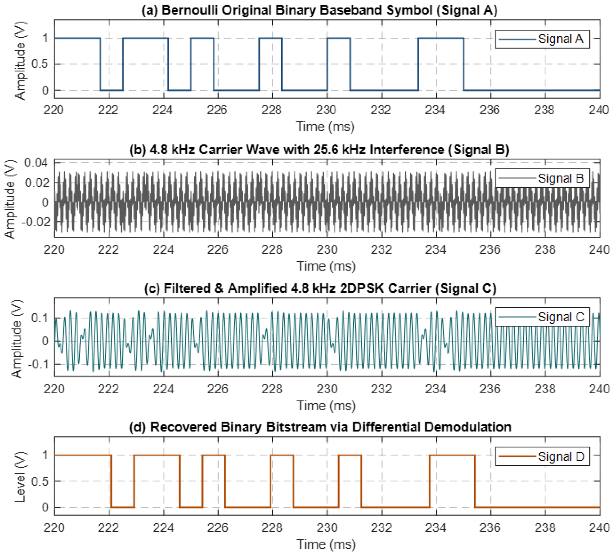
The full-chain simulation waveforms for the 2DPSK physical transmission and microcontroller software delay-coherent demodulation are illustrated in Figure 7 (over a steady-state observation window of 220–240 ms). The original Bernoulli binary baseband symbol signal generated by the source at a symbol rate of 1200 bps is DBPSK-modulated onto a 4.8 kHz carrier. During channel transmission, strong high-frequency out-of-band interference at 25.6 kHz and noise are introduced, causing severe distortion in the time-domain envelope of the received signal and completely submerging the modulated carrier in high-frequency glitches. After passing the noisy signal through a fourth-order Butterworth bandpass filter centered at 4.8 kHz paired with a gain amplification module, the strong interference components are effectively suppressed, restoring the waveform to a clean 4.8 kHz 2DPSK sinusoidal carrier with an amplitude of approximately ±0.12 V. Clear 180° phase-reversal characteristics are visibly displayed at the baseband symbol transition moments. Within the software demodulation unit, the filtered signal is split into two paths: one path undergoes a software delay of one symbol period (approximately 0.83 ms) before being multiplied by the direct path signal. The product signal then passes through a low-pass filter to eliminate the double-frequency carrier components, extracting a baseband envelope that reflects the relative phase difference between adjacent symbols. Finally, the bitstream is reconstructed via zero-crossing hard decision and a zero-order hold. As shown in Figure 7d, the reconstructed binary bitstream waveform maintains high consistency with the original transmitted symbols in both topological morphology and timing, achieving error-free reconstruction and validating the algorithm’s superior anti-interference performance and engineering reliability.
Figure 7.
Comparison of simulated waveforms.
4. Analog Front-End and Costas Phase-Locked Demodulation for the 2PSK Clock Synchronization Link
4.1. Signal Recovery Circuit Design
Unlike the 2DPSK data link, the 2PSK link carries a high-precision clock synchronization signal at 25.6 kHz, with its demodulation core relying on a digital Costas phase-locked loop (PLL) to achieve coherent demodulation and high-precision phase tracking. Owing to the higher carrier frequency of 25.6 kHz, the signal suffers more severe attenuation during coupling transmission due to the coil skin effect and channel dissipation, resulting in a millivolt-level induced signal at the receiving end. Furthermore, coherent demodulation and high-precision analog-to-digital conversion (ADC) sampling impose significantly stricter demands on the SNR, common-mode noise rejection capability, and dynamic voltage range compared to non-coherent differential demodulation. Directly adopting a single-stage MFB amplification circuit identical to that of the 2DPSK link would cause the weak signal to be submerged by the op-amp’s input noise, while making it difficult to simultaneously satisfy high-gain amplification and common-mode noise suppression. Therefore, a three-stage analog front-end (AFE) circuit—comprising passive high-impedance filtering, differential-to-single-ended noise rejection, and multistage active high-gain amplification—was specifically designed for the 2PSK receiver to ensure high-fidelity band extraction and amplitude matching of the high-frequency weak signal prior to entering the digital coherent demodulation loop.
4.1.1. Design of Passive Bandpass Filter
Due to the weak electromagnetic induction drive capability of the receiving coil, the AFE circuit must strike a balance between high input impedance and low noise introduction [35,36,37]. If active devices were directly employed for the first-stage amplification or filtering, the input noise of the operational amplifiers would be easily introduced and amplified, thereby submerging the weak induced electrical signals. Therefore, the first-stage filter adopts a passive network topology, with the core objective of accomplishing preliminary frequency band selection while minimizing additional noise brought by active components.
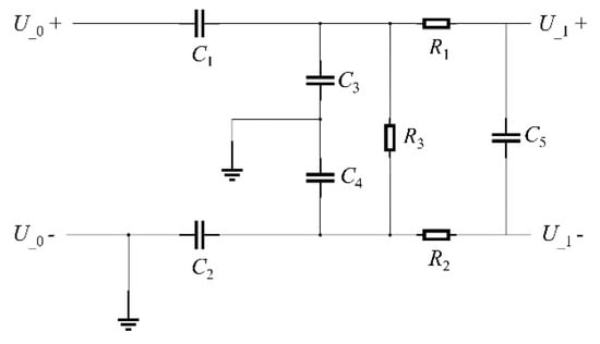
The circuit structure of the first-stage passive bandpass filter is illustrated in Figure 8. The weak differential electrical signal U0 induced by the receiving coil is fed into this network in differential form. To preserve the phase characteristics of the input signal and prevent coil loading effects, the circuit adopts a high input impedance design. Although high input impedance induces a small degree of attenuation within the passband, this attenuation can be fully compensated for by gain in subsequent active bandpass filter stages. Consequently, the core function of this stage is to complete preliminary signal frequency selection and impedance matching without introducing active component noise, delivering a preliminary filtered signal U1 to downstream stages. The transfer function of this circuit is derived as follows:
Figure 8.
Schematic image of the first-stage passive high-impedance bandpass filter circuit.
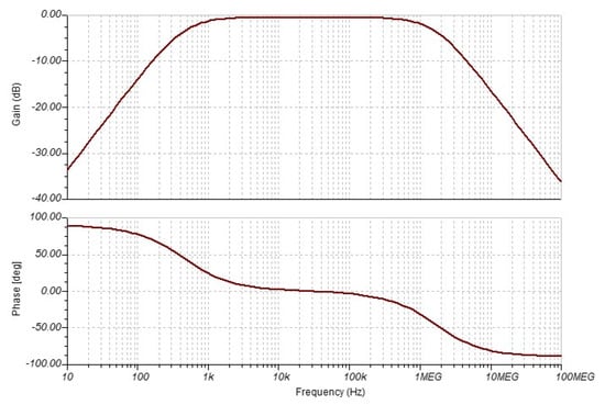
As indicated by the circuit topology, the resistor–capacitor (RC) components within the filter network impose frequency-response suppression on both low-frequency and high-frequency components, thereby endowing the circuit with dual filtering characteristics of high-pass and low-pass responses. The amplitude–frequency response curve of this circuit is illustrated in Figure 9. Simulation results demonstrate that the passband range is set to 10~200 kHz, fully covering the 25.6 kHz carrier frequency and the 12.8 kHz signal bandwidth requirements. Within the passband, the signal undergoes an attenuation of approximately 1 dB, which aligns with the physical characteristics of high input impedance circuits. When the signal frequency drops below 1 kHz or exceeds 300 kHz, the amplitude attenuates sharply, achieving an out-of-band suppression ratio of up to approximately 35 dB and thus validating the functional design of the passive filter circuit.
Figure 9.
Amplitude–frequency response and phase characteristic curves of the first-stage passive high-impedance bandpass filter circuit.
4.1.2. Design of Differential-to-Single-Ended Circuit
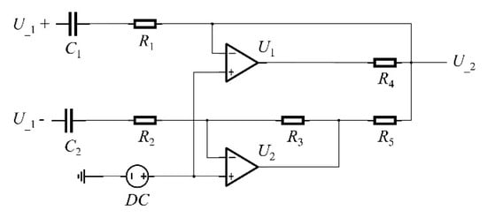
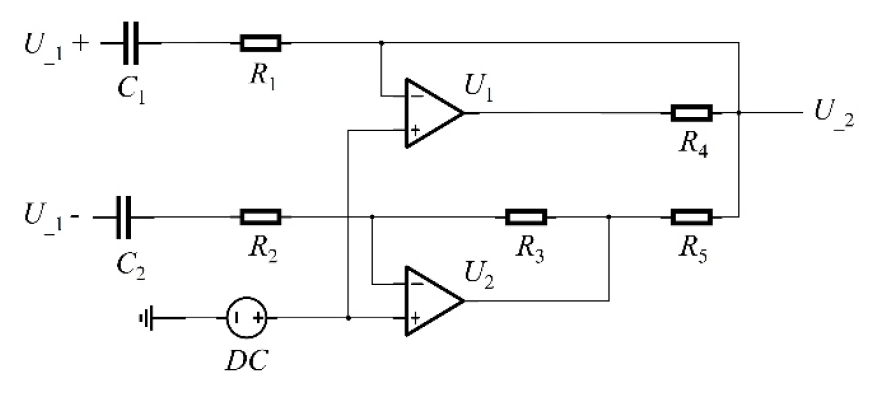
After passing through the first-stage passive bandpass filter, the signal U1 undergoes preliminary frequency selection; however, its output remains in differential form, which cannot directly feed into subsequent high-gain single-ended amplification circuits. Therefore, the second-stage circuit is designed to convert the differential signal U1 into a single-ended signal U2, while establishing a unified DC bias voltage and providing moderate pre-amplification gain. The circuit topology of the second-stage differential-to-single-ended converter is illustrated in Figure 10. The input signal U1 is fed in differential mode into the inverting and non-inverting input terminals of the operational amplifier. By adopting symmetric network parameter configurations during circuit design and component selection, the common-mode rejection ratio of the circuit is maximized. This symmetric structure effectively suppresses common-mode interference noise introduced by the coil while delivering moderate voltage gain. Simultaneously, introducing a DC reference voltage at the non-inverting terminal shifts the AC midpoint of the 2PSK signal to a specified DC level, generating a single-ended output signal U2 with a defined DC bias. The transfer function of this circuit is derived as follows:
Figure 10.
Schematic image of the second-stage differential-to-single-ended conversion and DC biasing circuit.
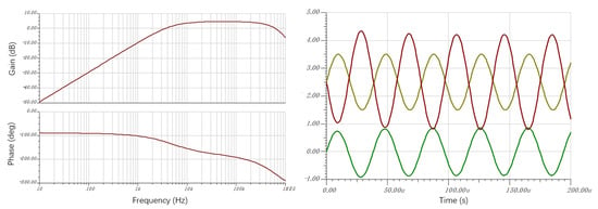
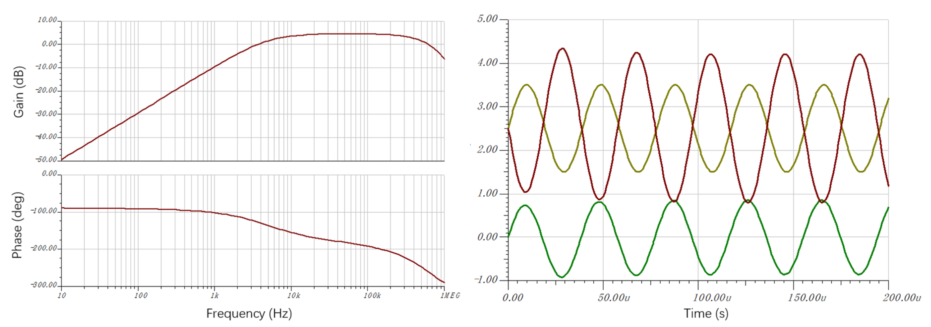
The time-domain waveform and amplitude–frequency response curves of the circuit are shown in Figure 11. Waveform analysis indicates that after passing through the first-stage passive filter, the output signal is centered at 0 V. When a carrier signal with an input amplitude of 1 V (a normalized simulation setting, whereas the actual induced signal is at the mV level) and a frequency of 25.6 kHz is applied, a 2.5 V DC bias voltage is successfully superimposed onto the signal processed by the differential-to-single-ended circuit. The AC frequency response curve demonstrates that within the passband range of 10–200 kHz, the circuit delivers a voltage gain of approximately 4~5 dB. This successfully provides preliminary amplification for the weak millivolt-level signal, preventing it from being submerged by system noise during transmission to subsequent high-gain stages.
Figure 11.
Simulated time-domain waveform and amplitude–frequency response curves of the second-stage differential-to-single-ended circuit.
4.1.3. Design of Cascaded Active Bandpass Filter
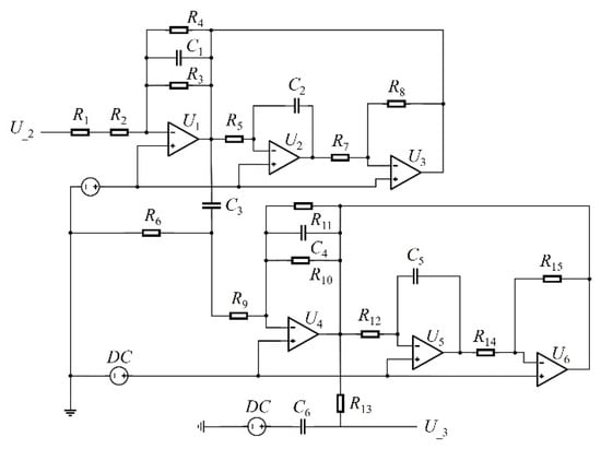
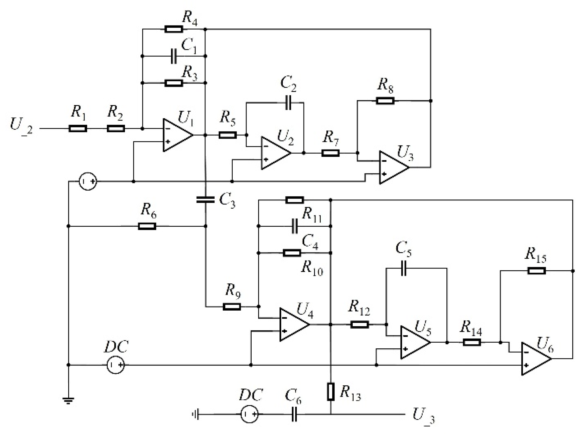
After processing by the second-stage differential-to-single-ended circuit, the single-ended signal receives preliminary amplification; however, the cumulative gain remains insufficient to satisfy the dynamic range requirements for subsequent ADC and digital coherent demodulation. Consequently, the third-stage circuit adopts a high-gain active bandpass filter based on a multistage op-amp cascaded topology, as illustrated in Figure 12. Due to the relative complexity of the circuit structure, it is decomposed into three sub-functional modules: the upper section consists of the first second-order bandpass filter composed of an operational amplifier; the middle section comprises an AC-coupling and voltage-divider network formed by a RC network; and the lower section contains the second bandpass filter formed by another operational amplifier.
Figure 12.
Schematic image of the third-stage high-gain cascaded active bandpass filter circuit.
In circuit parameter design, adjusting the resistance and capacitance values of the first bandpass filter section allows for precise tuning of the center frequency, while modifying the feedback resistance adjusts both the passband bandwidth and gain. Upon entering the intermediate voltage-divider network, the coupling capacitor isolates residual DC components from the preceding stage; the signal then enters the lower filter section to complete a second stage of frequency selection and amplification, yielding a pure 25.6 kHz sinusoidal signal. Functionally, this combined circuit is equivalent to a high-order cascaded bandpass filter.
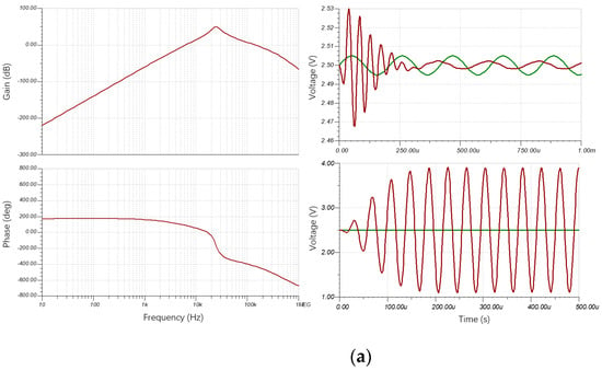
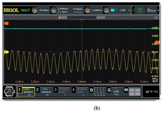
The simulated and measured amplitude–frequency response results of this filter stage are shown in Figure 13. The amplitude–frequency response curve shows that the passband range is strictly confined between 12.6 and 35.6 kHz, achieving a signal gain of 54 dB at the 25.6 kHz center carrier frequency—sufficient to amplify weak induced signals into the optimal voltage range for precise subsequent ADC sampling. The roll-off on both sides of the passband is extremely sharp, with a stopband attenuation capability reaching 60 dB, enabling deep suppression of low-frequency marine environmental noise and high-frequency switching noise. In a time-domain simulation combining a 4.8 kHz interference signal and a 25.6 kHz target signal (both with input amplitudes of 5 mV), the 4.8 kHz signal is attenuated to below 1 mV within 250 μs, while the 25.6 kHz clock signal amplitude is boosted to 1.5 V, successfully achieving high-quality frequency-selective amplification.
Figure 13.
Simulated and measured amplitude–frequency response results. (a) Amplitude–frequency characteristics and stopband attenuation response curves. (b) Measured circuit waveforms of the third-stage high-gain cascaded active bandpass filter.
In summary, the three-stage analog front-end circuit—comprising passive bandpass filtering, differential-to-single-ended conversion, and two-stage active bandpass filtering—achieves high-impedance matching, common-mode noise suppression, DC bias superimposition, steep bandpass frequency selection, and high-gain amplification. This circuit successfully addresses the challenges of severe signal attenuation and crosstalk in inductively coupled channels, providing guaranteed signal quality for downstream high-speed ADC sampling and Costas loop digital coherent demodulation.
4.2. Design of Coherent Demodulation Algorithm Based on Costas Loop
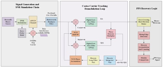
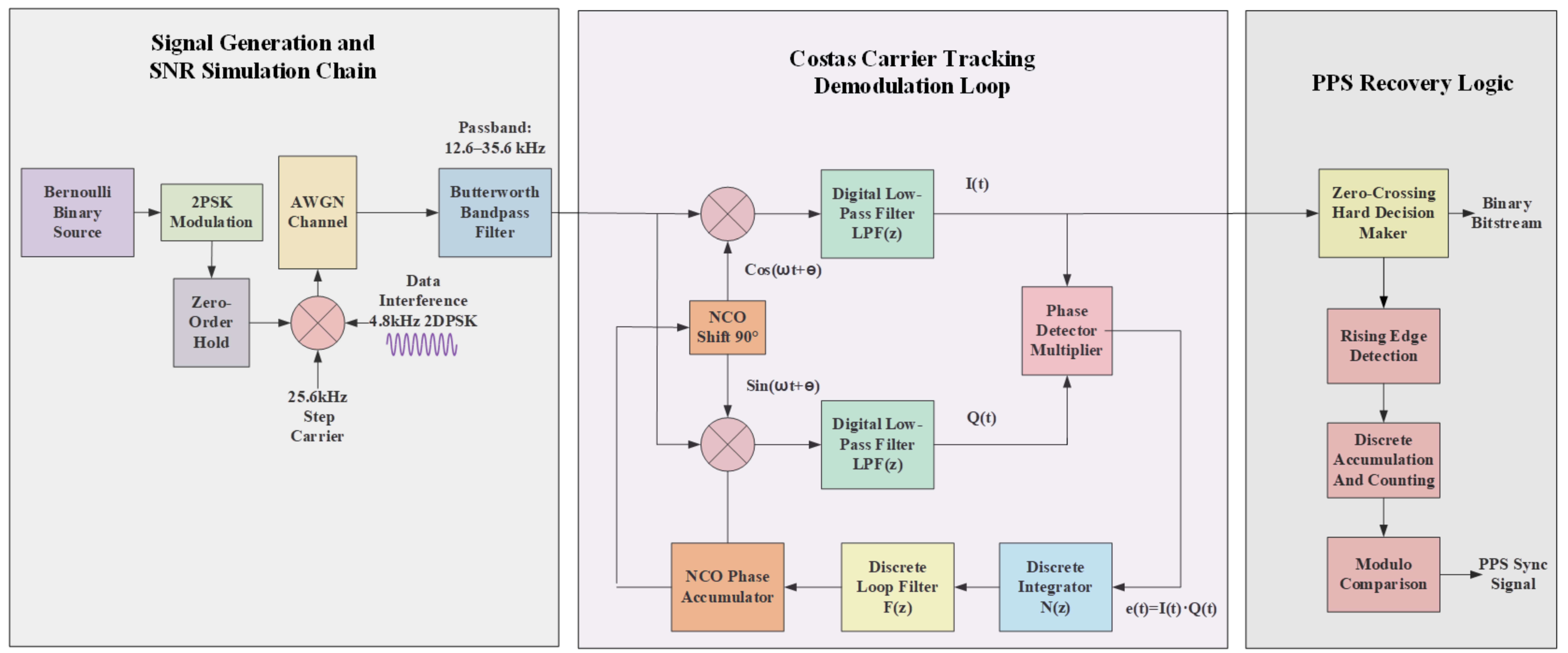
To efficiently achieve high-precision phase locking and clock synchronization recovery of the 25.6 kHz 2PSK signal in resource-constrained microcontrollers, this paper constructs a software–hardware co-demodulation architecture based on a digital Costas PLL [38] and timer edge capture. A system-level simulation model was established in the Simulink environment, as illustrated in Figure 14. This model encompasses three major modules: the signal generation and SNR simulation link, the Costas carrier tracking and demodulation loop, and the PPS pulse and clock synchronization recovery logic. It completes the entire process from signal modulation and channel impairment simulation to carrier synchronization and clock extraction.
Figure 14.
Block image of the system model.
In the signal generation and SNR simulation stage, a Bernoulli binary source operating at a symbol rate of 1000 bps undergoes BPSK modulation and zero-order hold processing before being mixed with a 25.6 kHz carrier. Subsequently, the modulated signal is introduced into an Additive White Gaussian Noise channel model. In this algorithm-level simulation, this channel model is primarily utilized to evaluate the fundamental algorithmic performance of the digital Costas loop—specifically encompassing phase detection, filtering, and phase tracking—under a controlled Gaussian background noise environment. As the core of the software demodulation unit, the Costas carrier tracking and demodulation loop completes quadrature down-conversion by multiplying the input signal with the quadrature component sin(ω0t + θ) and in-phase component cos(ω0t + θ) generated by a local numerically controlled oscillator (NCO), respectively. After passing through digital low-pass filters LPF(z) to eliminate the double-frequency carrier components, the two-path signals yield the extracted in-phase baseband component I(t) and quadrature baseband component Q(t). The phase detector multiplier uses an error signal e(t) = I(t)·Q(t) to reflect the phase offset, dynamically adjusting the output frequency and phase of the NCO via a discrete loop filter F(z) and a discrete integrator N(z). This forms a closed-loop tracking system that achieves precise phase locking onto the 25.6 kHz carrier.
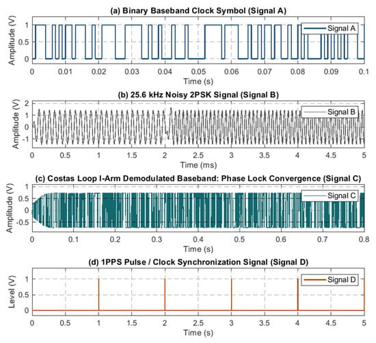
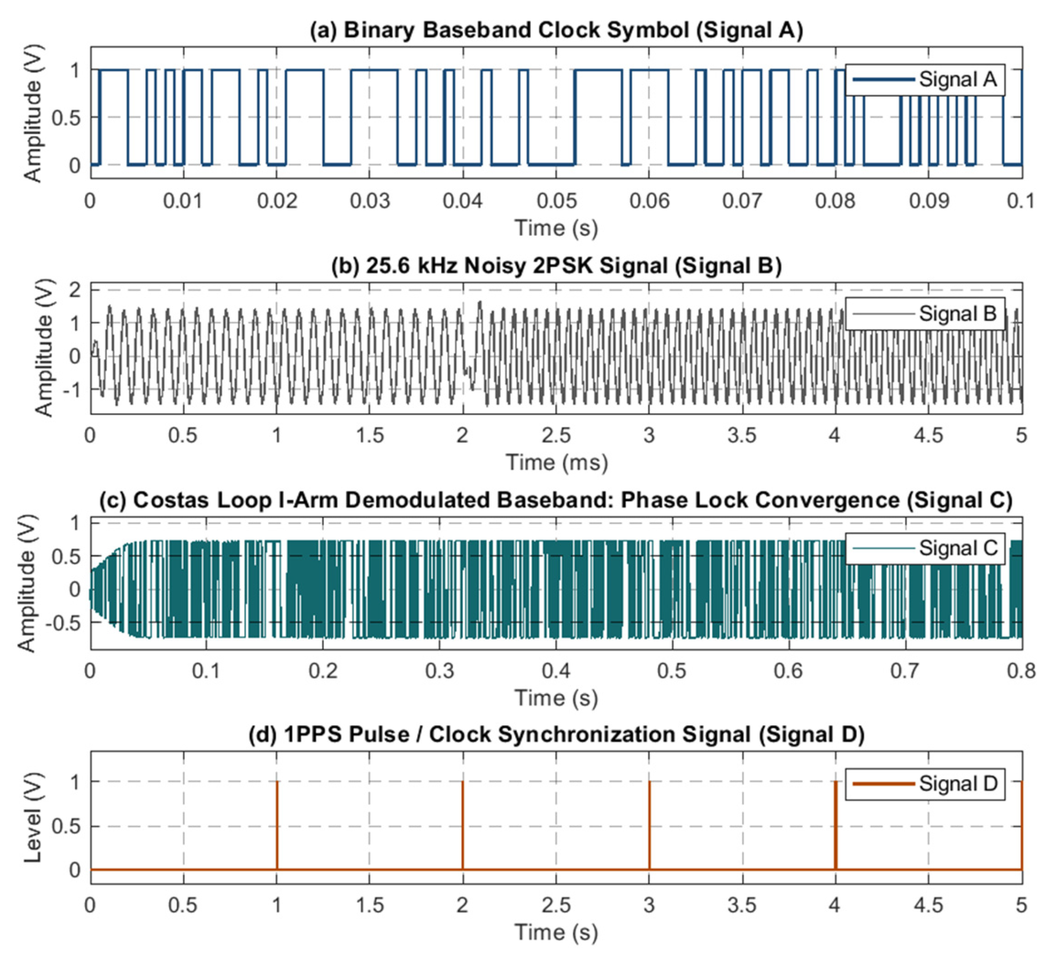
To evaluate the phase acquisition capability and clock synchronization response characteristics of the Costas carrier tracking loop under the software–hardware co-design architecture, systematic simulation experiments were conducted. The test waveforms are illustrated in Figure 15. The Bernoulli binary baseband data signal generated by the source at a symbol rate of 1000 bps (Figure 15a) is modulated onto a 25.6 kHz carrier and passed through an additive white Gaussian noise channel before being fed into the analog front-end equivalent circuit. After frequency selection and high-gain amplification, the weak induced signal is boosted to a 25.6 kHz 2PSK signal with a peak-to-peak amplitude of approximately ±1.5 V (Figure 15b), significantly improving SNR fed into the Costas loop. Subsequently, the high-speed sampled signal enters the digital demodulation loop. Under the stress condition where an initial phase offset exists in the receiving NCO, the in-phase demodulated baseband signal achieves rapid phase error tracking and closed-loop convergence within 0.1 s, with its amplitude recovering and stabilizing into the ±0.75 V full-scale range (Figure 15c)—validating the functional mechanism of the loop’s closed-loop feedback control. Once carrier phase lock is established, the baseband signal undergoes hard decision and rising-edge capture, working in tandem with discrete counting and modulo comparison logic to reconstruct the synchronized clock. Consequently, a high-precision PPS signal with a period of 1 s and phase jitter controlled at the microsecond level is successfully output (Figure 15d).
Figure 15.
Simulated end-to-end phase-locked demodulation and PPS clock synchronization reconstruction waveforms for the 2PSK signal.
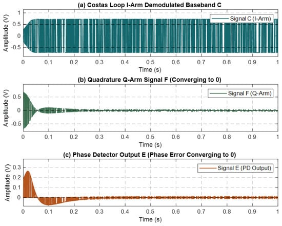
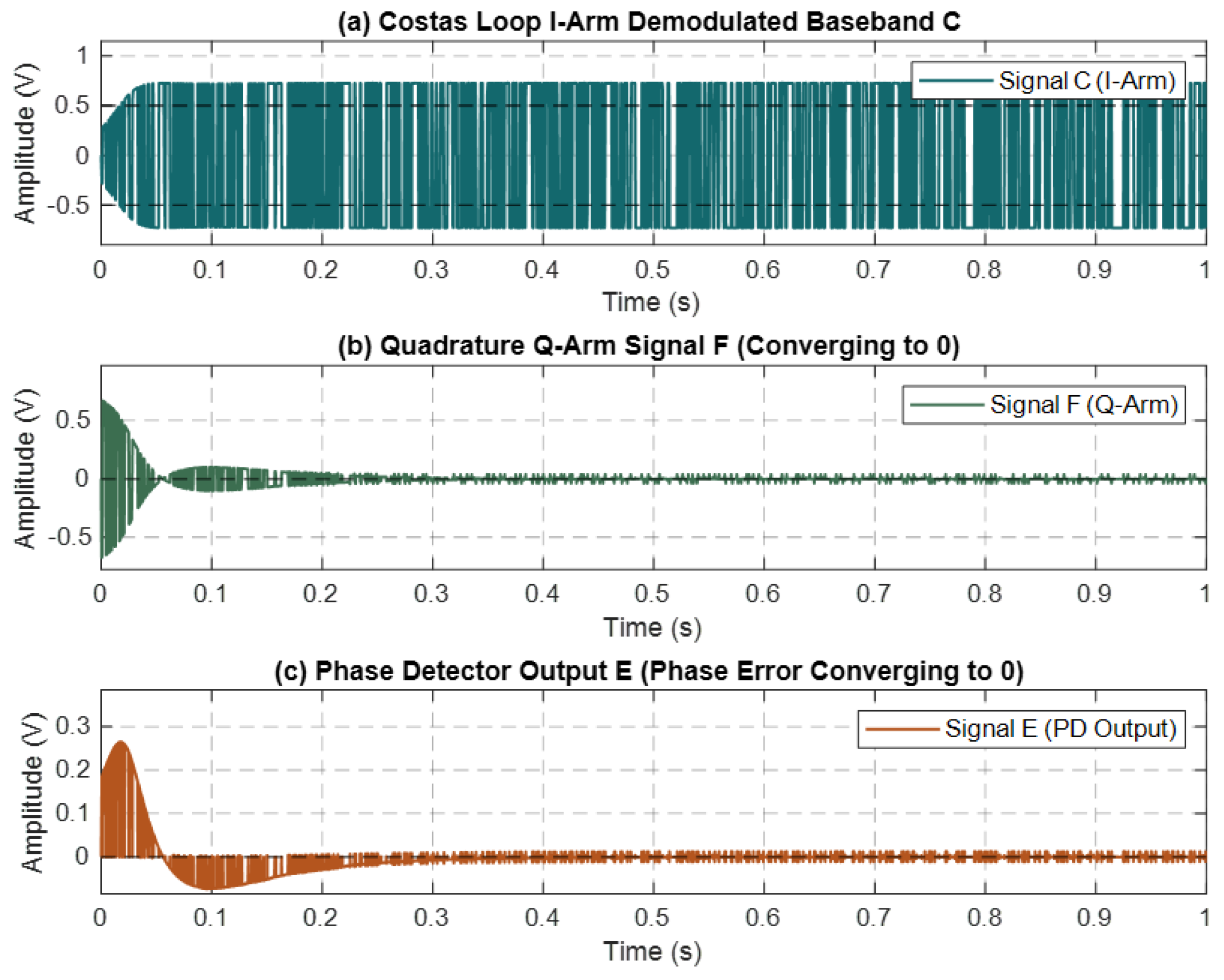
Furthermore, as shown in Figure 16, the dynamic convergence process of the Costas loop further elucidates its coherent demodulation mechanism: within 0~0.1 s, the amplitude envelope of the in-phase I branch signal expands rapidly, recovering into a full-scale polar square wave; concurrently, as the phase control variable is dynamically adjusted, the quadrature Q branch signal attenuates swiftly within 0~0.1 s and vanishes to zero following minor residual oscillations between 0.1 and 0.2 s. Meanwhile, the phase error signal—generated at the output of the phase detector multiplier—is rapidly smoothed through the joint operation of the loop filter and discrete integrator, converging to around 0 V within 0.2 s. These findings comprehensively validate the correctness and engineering effectiveness of the software–hardware co-design architecture combining analog front-end hardware frequency selection/amplification with software Costas phase-locked demodulation.
Figure 16.
Closed-loop dynamic convergence curves of Costas loop In-phase (I-arm), Quadrature (Q-arm), and Phase Detector Error (E-signal).
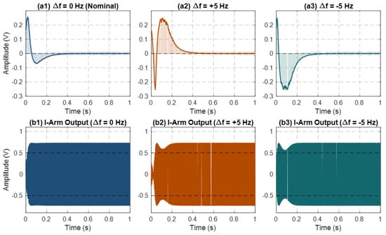
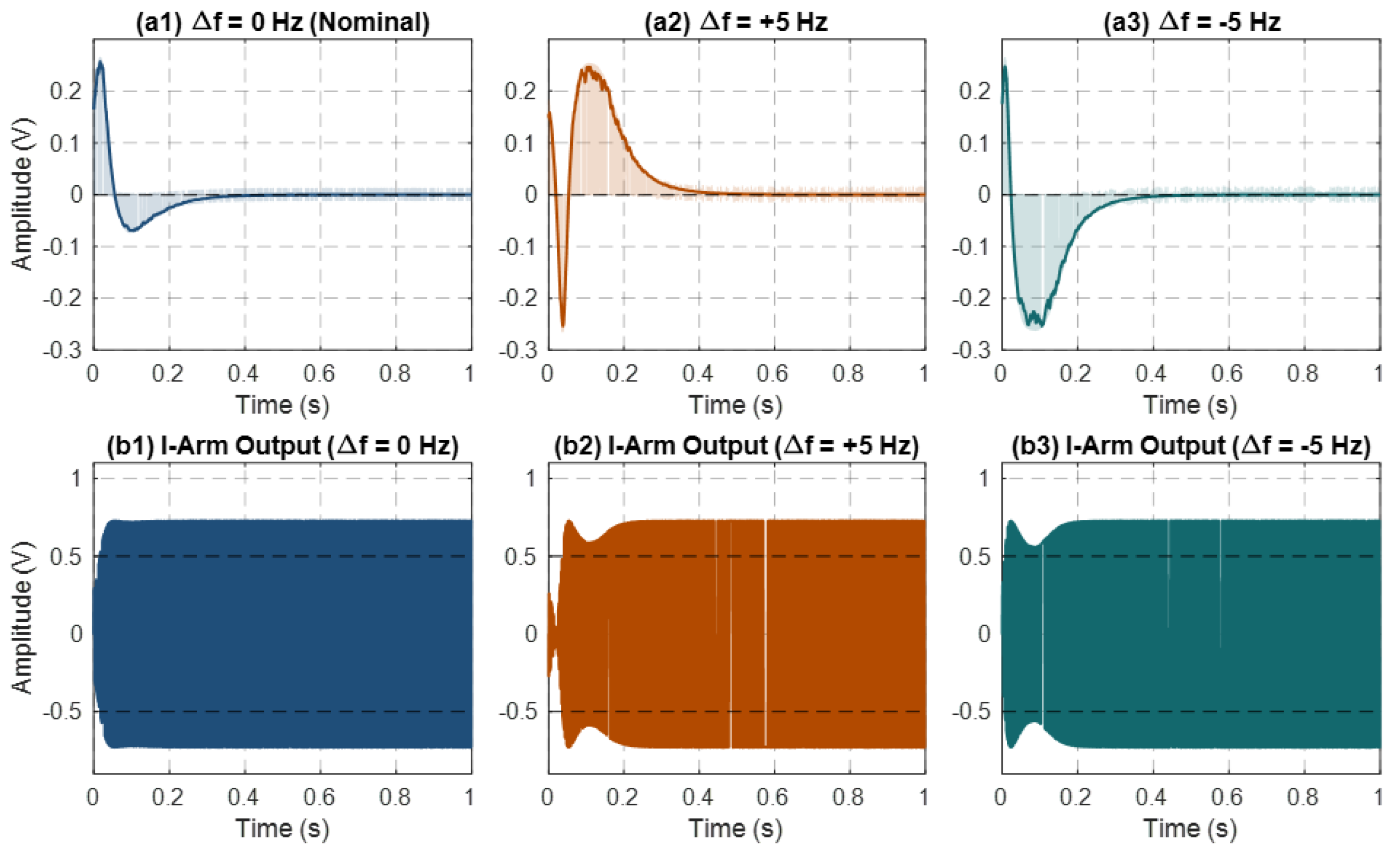
Furthermore, to address the slight frequency offsets induced by crystal oscillator temperature drift and mooring motion in real underwater channels, this study quantitatively evaluates the dynamic acquisition bandwidth and tracking margin of the Costas loop under non-ideal conditions. Carrier frequency offsets (CFOs) of ±5 Hz are respectively introduced into the 25.6 kHz carrier, and the corresponding simulated responses are illustrated in Figure 17. The test results indicate that both the phase detector error signal and the in-phase (I-arm) demodulated baseband exhibit excellent convergence characteristics under various frequency offset perturbations: under zero-offset conditions, the phase error smoothly converges to zero within 0.20 s. Conversely, under the condition of superimposed ±5 Hz dynamic frequency offsets, benefiting from the effective suppression of underwater broadband noise by the narrow equivalent noise bandwidth, the loop filter and discrete integrator accomplish a smooth transition from frequency pull-in to a steady-state phase lock within 0.40 s. No phase skipping or loss-of-lock phenomena occur throughout the entire process, and the in-phase demodulated baseband signal robustly recovers into a full-scale polar square wave of approximately ±0.7 V.
Figure 17.
Dynamic tracking performance and demodulated baseband waveforms of the Costas loop under different CFO.
5. Experiments and Analysis
To comprehensively evaluate the overall performance of the dual-carrier modulated inductively coupled module, systematic experimental tests were conducted in both a controlled laboratory environment and a nearshore real-water environment. For the data communication link based on 2DPSK modulation, the evaluation focused on data transmission success rate and BER performance. For the clock synchronization mechanism based on 2PSK modulation, the quantitative metrics of synchronization error and its key influencing factors were thoroughly analyzed.
To rigorously and objectively evaluate the performance of the 2DPSK data communication link, this paper employs several standard metrics for statistical evaluation. Specifically, the Packet Reception Ratio (PRR) represents the proportion of packets where the frame header is successfully captured and demodulation is triggered, while the Packet Loss Ratio (PLR) indicates the proportion of packets that remain entirely undetected due to severe signal attenuation or loss of lock. For received packets, the Corrupted-Packet Ratio (CPR) defines the proportion of defective packets that fail the cyclic redundancy check (CRC), whereas the Error-Free Packet Delivery Ratio (PDR) represents the delivery proportion of completely error-free, valid packets that successfully pass verification. Furthermore, at the fundamental data level, the Bit Error Ratio (BER) measures the ratio of erroneously demodulated bits to the total number of transmitted bits, and the byte-level error rate oriented toward packet telemetry is concurrently denoted as the Byte Error Rate (ByER).
5.1. Laboratory Tests
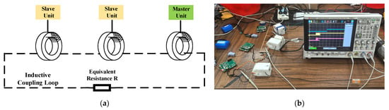
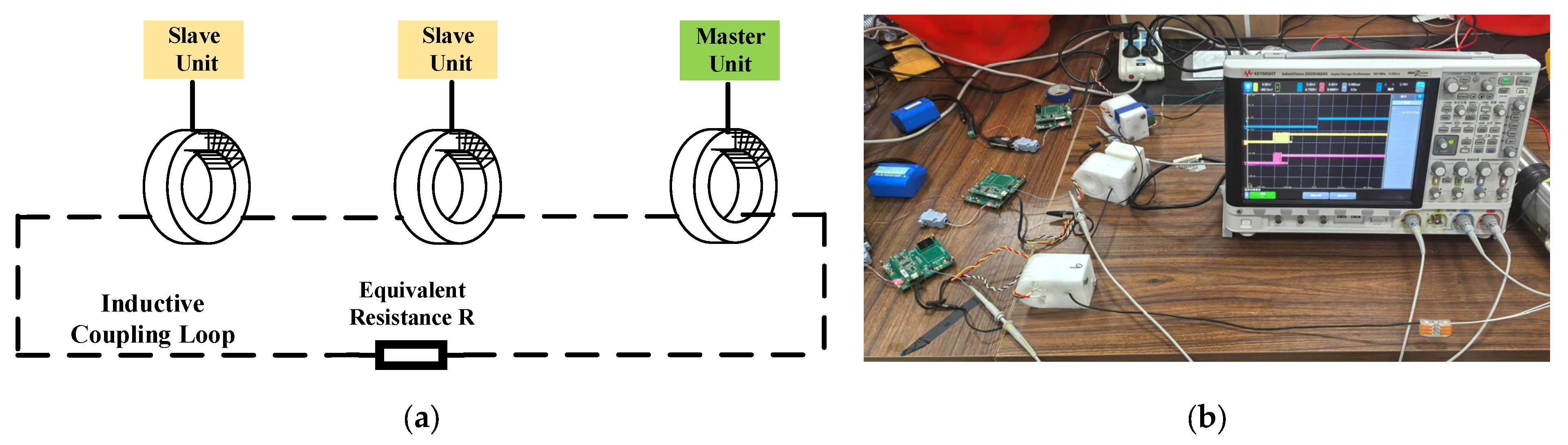
The system architecture and real-world testing setup for the laboratory experiments are shown in Figure 18. The system primarily consists of one master node and two slave nodes. The master node incorporates a dual-carrier modulation unit responsible for signal modulation and transmission. Each slave node integrates demodulation units corresponding to the respective modulation schemes to recover both the 2DPSK data signal and the 2PSK clock signal. The magnetic ring structures of all nodes are connected in series using a single-core insulated wire, with a 200 Ω load resistor inserted into the closed loop to equivalate the impedance characteristics of the seawater medium.
Figure 18.
Laboratory test. (a) Schematic image of laboratory inductive coupling synchronization test. (b) Image of the inductive coupling synchronization test.
Upon starting the experiment, the master node continuously transmitted fixed-format data packets of 100 Byte using 2DPSK modulation. Simultaneously, periodic PPS signals were generated, modulated via 2PSK, and injected into the loop through magnetic coupling. The slave nodes carried out parallel demodulation and output of both types of signals. In the 2DPSK data communication test, the receiving data integrity at the slave nodes was verified to quantitatively evaluate transmission metrics, including bit/byte error rate and communication success rate. In the 2PSK clock synchronization test, while modulating and transmitting the signal, the master node output a reference indicator voltage level via a general-purpose I/O port; upon successfully recovering the PPS signal, each slave node triggered its corresponding response indicator level. The absolute error of 2PSK clock synchronization was characterized by measuring the precise time difference between the master reference level and the slave response level using an oscilloscope.
During the 2DPSK communication performance testing phase, the master node transmitted a cumulative total of 32 data packets (3200 Byte in total). The measured statistical results are summarized in Table 2. The test results demonstrate that Slave Node 01 received all 32 packets, achieving a PRR of 100.0% and a PLR of zero. Among them, 31 packets were completely error-free while the 20th packet suffered a burst error of 3 bytes (corresponding to 10 flipped bits), resulting in a CPR of 3.13%, an error-free PDR of 96.88%, and a BER of 0.039%. Slave Node 02 successfully captured and demodulated 29 data packets without any bit errors, yielding both a PRR and error-free PDR of 90.63%, a PLR of 9.38%, and a BER of zero (Detailed data is in the Supplementary Materials “Test data”). The synchronization error of Slave Node 01 was distributed between 97 and 156 μs, while that of Slave Node 02 ranged from 122 to 154 μs. These results demonstrate that the system possesses high-stability synchronization capabilities on the microsecond scale under a controlled environment.
Table 2.
Statistical summary of 2DPSK communications.
5.2. Nearshore Field Tests
In light of the objective discrepancies between using resistive equivalence to simulate seawater impedance in laboratory testing and the actual seawater environment, this study further conducted in situ nearshore sea trials. The nearshore testing utilized the real seawater medium to form a conductive loop by immersing the metallic electrodes at both ends of the inductively coupled cable into the sea. The test system was deployed along a 300 m inductively coupled cable, with the master node deployed at the head end of the cable, and two slave nodes (ID01 and ID02) placed at the middle and tail ends, respectively, the experimental environmental parameters are shown in Table 3.
Table 3.
Experimental environmental parameters.
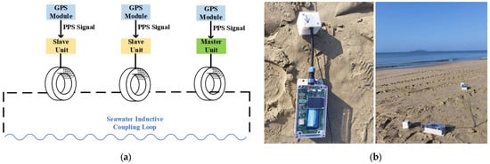
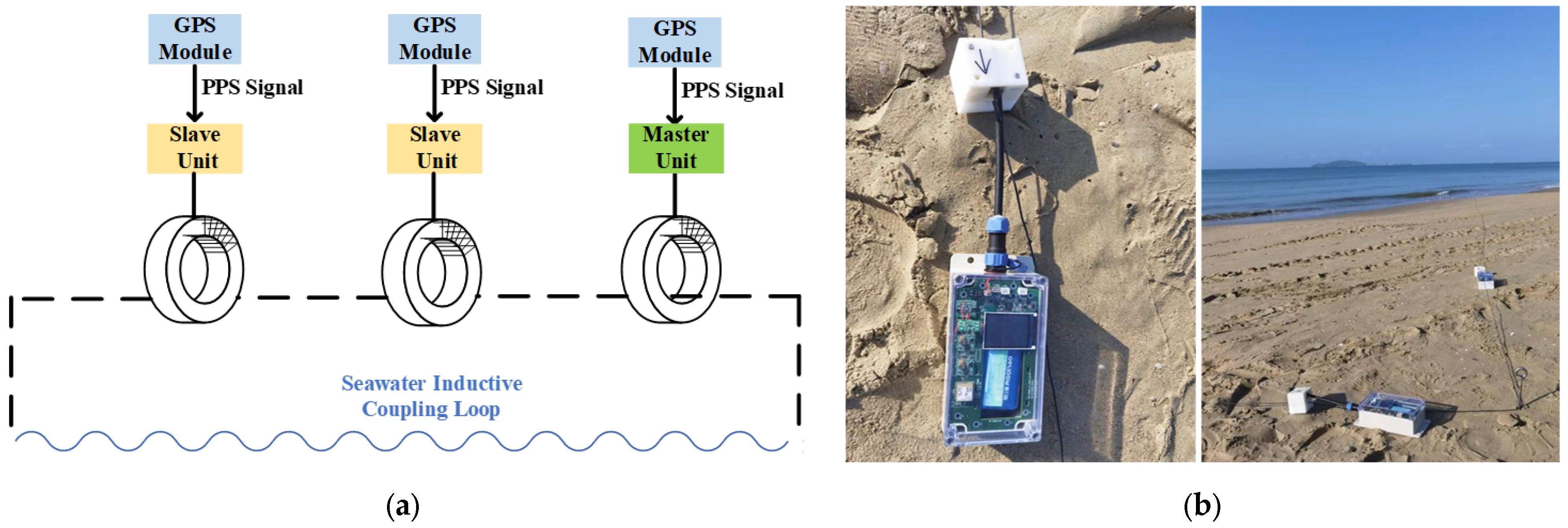
To address the challenge in nearshore testing where the direct oscilloscope measurement of time delay is unfeasible due to the large spatial separation between master and slave nodes, a synchronization test module based on standard GPS PPS signals was designed, as shown in Figure 19. Each module incorporates a GPS receiver unit to acquire the standard PPS reference, the parameters are shown in Table 4. During the test, the master node continuously broadcasted its local GPS PPS signal via inductive coupling. Simultaneously, the slave nodes demodulated the master’s broadcasted PPS signal while receiving their own local GPS PPS reference. At the slave side, an external interrupt was triggered by the local GPS PPS signal to start a high-precision counter, which was subsequently stopped upon successfully demodulating and recovering the master’s PPS signal; this recorded counter value directly represents the real-time synchronization error between the master and slave nodes.
Figure 19.
Nearshore field test. (a) Structural image of the synchronization test module. (b) Test Scenarios.
Table 4.
Experimental equipment specifications.
During the continuous field test, the master node transmitted a total of 173 packets. Slave Node 01 acquired 162 packets, yielding a PRR of 93.64% and a PLR of 6.36%; with 9 corrupted packets detected (CPR of 5.20%), the error-free PDR reached 88.44% and the evaluated BER was 0.141% (108 erroneous bytes across 162 received packets). For Slave Node 02, affected by hydrodynamic cable sway, 155 packets were captured, achieving a PRR of 89.60% and an error-free PDR of 83.24% with 11 corrupted packets (CPR of 6.36%), maintaining a BER of 0.212%. Detailed statistics are summarized in Table 5 (Detailed data is in the Supplementary Materials “Test data”). Meanwhile, the recovery results of the 2PSK-modulated PPS signal indicate that the synchronization error of Slave Node 01 ranged from 122 μs to 157 μs, whereas that of Slave Node 02 ranged from 153 μs to 203 μs.
Table 5.
Statistical summary of 2DPSK communications.
In summary, the results from both laboratory and nearshore tests validate the feasibility and effectiveness of FDM dual-carrier modulation scheme. The 2DPSK-based data communication success rate is maintained at approximately 90%, with the BER remaining at a low level (mostly below 1.0%), while the 2PSK-based clock synchronization error is controlled within the range of 100 μs to 200 μs. Utilizing hardware demodulation circuits and software demodulation algorithms, the two modulated signals are efficiently separated and accurately recovered within a single-conductor cable loop. Comparative analysis reveals that performance metrics in the nearshore field test are slightly degraded compared to those in the controlled laboratory environment. The primary reasons are twofold: first, the seawater medium loop exhibits complex composite capacitive and resistive impedance characteristics, presenting a harsher channel condition than the pure resistive simulation in the laboratory; second, after passing through two stages of inductive coupling, the modulated signals undergo severe waveform amplitude and phase distortion, increasing the probability that the software demodulation stage misidentifies them as anomalous signals and filters them out, which in turn leads to a reduced communication success rate and an increased error rate.
6. Conclusions
To address the engineering requirement of deep-sea real-time communication subsurface mooring systems for parallel high-precision clock synchronization and bidirectional data communication over a single plastic-coated steel cable loop, this paper proposes and implements a dual-carrier inductively coupled communication scheme based on FDM. The system employs 4.8 kHz 2DPSK modulation to carry minute-level data transmission and 25.6 kHz 2PSK modulation to carry microsecond-level clock synchronization signals. Through targeted hardware designs—including a MFB narrow bandpass filter and a three-stage AFE circuit—the challenges of inter-frequency crosstalk and channel attenuation inherent in a single-loop dual-frequency signal are successfully overcome. Combined with software algorithms including delay differential demodulation and a digital Costas coherent PLL, hardware–software co-processing for multi-node demodulation and clock recovery is realized. Results from laboratory testing and a 300 m in situ nearshore sea trial demonstrate that the system’s clock synchronization accuracy is better than 200 μs, while maintaining a PRR above 89.60%, an error-free PDR exceeding 83.24%, and a physical-layer BER below 0.22%, comprehensively validating the feasibility and engineering value of this concurrent dual-carrier architecture in complex aquatic environments. Future research will focus on conducting long-term, deep-sea integrated sea trials to systematically evaluate the impacts of environmental temperature variations and extended cable lengths on link stability, and to quantitatively assess the performance degradation induced by simultaneous dual-carrier operation compared with separate single-carrier modes. Furthermore, we will focus on adaptive channel equalization algorithms addressing the complex impedance characteristics of the seawater medium [39], alongside introducing forward error correction coding mechanisms to further enhance communication robustness and data throughput under severely distorted sea conditions.
Supplementary Materials
The following supporting information can be downloaded at: https://www.mdpi.com/article/10.3390/jmse14201898/s1.
Author Contributions
Conceptualization, S.Z. and P.L.; formal analysis, Z.S.; investigation, S.Z. and J.P.; methodology, C.T.; resources, S.Z. and C.T.; software, P.L.; supervision, H.W.; validation, S.Z. and H.W.; visualization, Z.S. and J.P.; writing—original draft preparation, S.Z. and P.L.; writing—review and editing, Z.S. and C.T. project administration, C.T. All authors have read and agreed to the published version of the manuscript.
Funding
This research was supported by the National Key R&D Program of China under Grant (No. 2023YFC3106400).
Institutional Review Board Statement
Not applicable.
Informed Consent Statement
Not applicable.
Data Availability Statement
The data presented in this study are available in this article (Tables and Figures).
Acknowledgments
We thank the Institute of Deep-Sea Science and Engineering, Chinese Academy of Sciences for providing sea trial opportunity.
Conflicts of Interest
The authors declare no conflicts of interest.
References
- Luo, P.; Song, Y.J.; Xu, X.Y.; Wang, C.; Zhang, S.W.; Shu, Y.Q.; Ma, Y.G.; Shen, C.; Tian, C.A. Efficient Underwater Sensor Data Recovery Method for Real-Time Communication Subsurface Mooring System. J. Mar. Sci. Eng. 2022, 10, 1491. [Google Scholar] [CrossRef] [Scilit]
- Wang, F.; Wang, J.N.; Xu, L.J.; Zhang, X.G.; Yan, S.F.; Chen, Y.H. The development of a new real-time subsurface mooring. J. Oceanol. Limnol. 2020, 38, 1080–1091. [Google Scholar] [CrossRef] [Scilit]
- Zhou, B.C.; Zhang, X.W.; Wan, X.Z.; Liu, T.M.; Liu, Y.Q.; Huang, H.; Chen, J. Development and Application of a Novel Tsunami Monitoring System Based on Submerged Mooring. Sensors 2024, 24, 6048. [Google Scholar] [CrossRef] [Scilit]
- Ouyang, Y.J.; Han, Y.F.; Wang, Z.Y.; He, Y.F. Underwater Network Time Synchronization Method Based on Probabilistic Graphical Models. J. Mar. Sci. Eng. 2024, 12, 2079. [Google Scholar] [CrossRef] [Scilit]
- Campagnaro, F.; Steinmetz, F.; Renner, B.C. Survey on Low-Cost Underwater Sensor Networks: From Niche Applications to Everyday Use. J. Mar. Sci. Eng. 2023, 11, 125. [Google Scholar] [CrossRef] [Scilit]
- Krishfield, R.; Toole, J.; Proshutinsky, A.; Timmermans, M.L. Automated Ice-Tethered Profilers for Seawater Observations under Pack Ice in All Seasons. J. Atmos. Ocean Technol. 2008, 25, 2091–2105. [Google Scholar] [CrossRef] [Scilit]
- Wen, H.; Yin, H.X.; Ji, X.Y.; Huang, A. Modeling and performance analysis of underwater wireless optical absorption, scattering, and turbulence channels employing Monte Carlo-multiple phase screens. Appl. Opt. 2023, 62, 6883–6891. [Google Scholar] [CrossRef] [Scilit]
- Li, S.Q.; Zhang, Z.C.; Zhang, Q.X.; Yao, H.Y.; Li, X.D.; Mi, J.J.; Wang, H.Y. Breakthrough Underwater Physical Environment Limitations on Optical Information Representations: An Overview and Suggestions. J. Mar. Sci. Eng. 2024, 12, 1055. [Google Scholar] [CrossRef] [Scilit]
- Li, Z.; Li, W.K.; Sun, K.; Fan, D.X.; Cui, W.C. Recent Progress on Underwater Wireless Communication Methods and Applications. J. Mar. Sci. Eng. 2025, 13, 1505. [Google Scholar] [CrossRef] [Scilit]
- Stojanovic, M.; Preisig, J. Underwater Acoustic Communication Channels: Propagation Models and Statistical Characterization. IEEE Commun. Mag. 2009, 47, 84–89. [Google Scholar] [CrossRef] [Scilit]
- Yoshioka, D.; Sakamoto, H.; Ishihara, Y.; Matstumoto, T.; Timischl, F. Power feeding and data-transmission system using magnetic coupling for an ocean observation mooring buoy. IEEE Trans. Magn. 2007, 43, 2663–2665. [Google Scholar] [CrossRef]
- Fougere, A.J.; Brown, N.L.; Hobart, E. Inductive Modem for Ocean Data Telemetry. Ocean. 91 Proc. 1991, 2, 1165–1170. [Google Scholar]
- Milburn, H.B.; McLain, P.D.; Meinig, C. ATLAS buoy—Reengineered for the next decade. In Proceedings of the Oceans’ 96 MTS/IEEE, Conference Proceedings Vols 1–3/Supplementary Proceedings, Fort Lauderdale, FL, USA, 23–26 September 1996; pp. 698–702. [Google Scholar]
- Stojanovic, M.; Catipovic, J.; Proakis, J.G. Adaptive Multichannel Combining and Equalization for Underwater Acoustic Communications. J. Acoust. Soc. Am. 1993, 94, 1621–1631. [Google Scholar] [CrossRef] [Scilit]
- Kisseleff, S.; Akyildiz, I.F.; Gerstacker, W. On Modulation for Magnetic Induction based Transmission in Wireless Underground Sensor Networks. In Proceedings of the 2014 IEEE International Conference on Communications (ICC), Sydney, NSW, Australia, 10–14 June 2014; pp. 71–76. [Google Scholar]
- Li, Z.; Deng, Y. The Application of Single-core Cable Transmission Technology to Ocean CTD Measurement. Ocean Technol. 2005, 3, 30–35. Available online: https://kns.cnki.net/kcms2/article/abstract?v=9TisLvyceEOD8hu_un7O3XNkht9b2iQXEmf8yKUfVR5x8GuVUYB4CyT7tSHlbYSmuxqh7nK0XhnaaemmTpsADCq_h-SfekdMGJy1FYEX4o68ZQK30-aT_pygGm8887TAB2vo9QUupwRqSyOFeKQXVwFKGcyT1brX80vuLizJb9GXPzyykpY8DQ== (accessed on 10 August 2026).
- Qiu, Z.R.; Zhang, Q.; Li, H.Z.; Zhang, X.W. Design of inductive coupling channel analysis system based on LabVIEW. J. Meas. Sci. Instrum. 2018, 9, 360–366. [Google Scholar]
- Zheng, Y.; Liu, Y.J.; Ren, Y.H.; Fei, C.; Zhang, S.J.; Li, H.Z. Orthogonal Frequency Division Multiplexing Adaptive Technology for Multinode Users of Seawater Channel Based on Inductively Coupled Mooring Chain. J. Ocean Univ. China 2023, 22, 1243–1252. [Google Scholar] [CrossRef] [Scilit]
- Zheng, Y.; Wang, X.R.; Zhang, X.W.; Li, H.Z.; Jin, X.Y. Improving transmission reliability of inductive coupling temperature-salinity-depth mooring cable system. Ocean Eng. 2018, 147, 488–495. [Google Scholar] [CrossRef] [Scilit]
- Kisseleff, S.; Akyildiz, I.F.; Gerstacker, W.H. Survey on Advances in Magnetic Induction-Based Wireless Underground Sensor Networks. IEEE Internet Things 2018, 5, 4843–4856. [Google Scholar] [CrossRef] [Scilit]
- Domingo, M.C. Magnetic Induction for Underwater Wireless Communication Networks. IEEE Trans. Antennas Propag. 2012, 60, 2929–2939. [Google Scholar] [CrossRef] [Scilit]
- Liu, Y.; Li, B.H.; Pan, L.Y.; Yao, S.Y.; Dong, Z.T.; Zhang, J.T.; Zhu, C.B.; Cui, S.M. Review on Development and Research of Underwater Capacitive Power Transfer. Energies 2024, 17, 6496. [Google Scholar] [CrossRef] [Scilit]
- Luo, T.C.; Zhang, S.W. Design of Underwater Wireless Power Transmission System Based on Inductive Coupling. J. Mar. Sci. Eng. 2023, 11, 1699. [Google Scholar] [CrossRef] [Scilit]
- Ren, Z.J.; Yuan, J.P.; Su, X.Y.; Bauer, R.; Xu, Y.; Mangla, S.; Camino, F.; Nam, C.Y.; Lu, M.; Shi, Y. Current divisions and distributed Joule heating of two-dimensional grid microstructures. Microsyst. Technol. 2021, 27, 3339–3347. [Google Scholar] [CrossRef] [Scilit]
- Dobakhshari, A.S.; Azizi, S. On Estimation of Zero-Sequence Impedances of Parallel Transmission Lines From Fault Data. IEEE Trans. Power Deliv. 2025, 40, 831–842. [Google Scholar] [CrossRef] [Scilit]
- Li, Z.S.; Li, D.J.; Lin, L.; Chen, Y. Design considerations for electromagnetic couplers in contactless power transmission systems for deep-sea applications. J. Zhejiang Univ. Sci. C 2010, 11, 824–834. [Google Scholar] [CrossRef] [Scilit]
- Zheng, Y.; Peng, B.; Song, R.J.; Liu, Y.J.; Li, H.Z. Design of an OFDM Algorithm for Improving the Transmission Performance of a Deep-Sea Long-Distance Electric Current Channel. J. Ocean Univ. China 2025, 24, 647–656. [Google Scholar] [CrossRef] [Scilit]
- Zheng, Y.; Zhang, S.J.; Fei, C.; Ren, Y.H.; Liu, Y.J. A method to improve multi-node power transmission efficiency of inductively coupled mooring cable. Rev. Sci. Instrum. 2022, 93, 054705. [Google Scholar] [CrossRef] [Scilit]
- Zhou, M.Z.; Wang, J.F.; Feng, X.; Sun, H.X.; Qi, J.; Lin, R.B. Neural-Network-Based Equalization and Detection for Underwater Acoustic Orthogonal Frequency Division Multiplexing Communications: A Low-Complexity Approach. Remote Sens. 2023, 15, 3796. [Google Scholar] [CrossRef] [Scilit]
- Zheng, Y.; Lu, Y.F.; Fei, C.; Li, H.Z. Design Method of an Ocean Induction Coupling Chain Communication System that Resists the Multipath Effect of a Seawater Channel. J. Ocean Univ. China 2021, 20, 87–93. [Google Scholar] [CrossRef] [Scilit]
- Cui, X.B.; Xu, J.Y.; Pang, S.; Li, X.F.; Li, H.Y. Design and Implementation of Inductively Coupled Power and Data Transmission for Buoy Systems. Energies 2023, 16, 4417. [Google Scholar] [CrossRef] [Scilit]
- Liu, B.J.; Teng, Z.S.; Zhong, H.W.; Tang, Q.; Deng, T.Y.; Ouyang, B. Low-Distortion Wideband Tunable Sinusoidal Oscillator Based on Multiple Feedback Band-Pass Filter for Impedance Measurements. IEEE Trans. Circuits-I 2026, 73, 1766–1776. [Google Scholar] [CrossRef] [Scilit]
- Ren, M.Y.; Zhang, R.D.; Jiang, X.L. BLE Transmitter with Multiple Feedback Filter for Low-Power IoT Applications. Mob. Netw. Appl. 2024, 29, 1190–1195. [Google Scholar] [CrossRef] [Scilit]
- Aboltins, A.; Tihomorskis, N. Software-Defined Radio Implementation and Performance Evaluation of Frequency-Modulated Antipodal Chaos Shift Keying Communication System. Electronics 2023, 12, 1240. [Google Scholar] [CrossRef] [Scilit]
- Kim, H.S.; Cha, H.K. A Low-Noise Biopotential CMOS Amplifier IC Using Low-Power Two-Stage OTA for Neural Recording Applications. J. Circuit Syst. Comp. 2018, 27, 1850068. [Google Scholar] [CrossRef] [Scilit]
- Zhou, Z.J.; Warr, P.A. A High Input Impedance Low Noise Integrated Front-End Amplifier for Neural Monitoring. IEEE Trans. BioMed Circ. S 2016, 10, 1079–1086. [Google Scholar] [CrossRef] [Scilit]
- Huynh, H.A.; Ronchini, M.; Rashidi, A.; Tohidi, M.; Farkhani, H.; Moradi, F. A Low-Noise High Input Impedance Analog Front-End Design for Neural Recording Implant. In Proceedings of the 2019 26th IEEE International Conference on Electronics, Circuits and Systems (ICECS), Genoa, Italy, 27–29 November 2019; pp. 887–890. [Google Scholar]
- Wang, W.Y.; Liang, Y.H. Necessary Condition for the Costas Loop to Track Desired Signal Under CW Interference. IEEE Trans. Commun. 2026, 74, 521–535. [Google Scholar] [CrossRef] [Scilit]
- Lin, Z.H.; Wang, L.; Peng, C.; Zhang, S.H. Direct Adaptive Multi-Resampling Turbo Equalizer for Underwater Acoustic Single-Carrier Communication. J. Mar. Sci. Eng. 2024, 12, 1271. [Google Scholar] [CrossRef] [Scilit]

Disclaimer/Publisher’s Note: The statements, opinions and data contained in all publications are solely those of the individual author(s) and contributor(s) and not of MDPI and/or the editor(s). MDPI and/or the editor(s) disclaim responsibility for any injury to people or property resulting from any ideas, methods, instructions or products referred to in the content. |
© 2026 by the authors. Licensee MDPI, Basel, Switzerland. This article is an open access article distributed under the terms and conditions of the Creative Commons Attribution (CC BY) license.