


Abstract
Pile–bucket foundation is a newly developed offshore wind turbine supporting structure created by combining a monopile and a bucket foundation. Current research mainly focuses on its bearing characteristics in homogeneous soil layers (e.g., pure sand and pure clay); however, field stratigraphy is normally in a layered distribution, which may alter the bearing mechanism of the pile–bucket foundation and lead to inconsistency in the prediction of the bearing capacity. In this study, three-dimensional finite element simulations are performed, and the static lateral bearing characteristics of pile–bucket foundation in layered sand–clay strata are investigated considering the impact of monopile size, bucket size, and sand/clay thickness ratio (Hs/Hc). Numerical results indicate that an increase in sand layer thickness could help increase the bearing capacity of the pile–bucket foundation, especially as Hs/Hc increases from 0.5 to 1. Then, hyperbolic p-y models are introduced to calculate the lateral load–displacement curves of the pile–bucket foundation, which is divided into three sections: the bucket section and pile section in sand and clay, respectively. The two controlling factors of the p-y model, the initial stiffness and the ultimate lateral resistance, are modified based on numerical results. The modified p-y model provides satisfactory predictions of the pile deflection and the moment distribution of pile–bucket in layered sand–clay strata and could serve as a framework in more complicated soil deposits, such as clay-over-sand or multi-layer.
1. Introduction
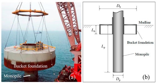
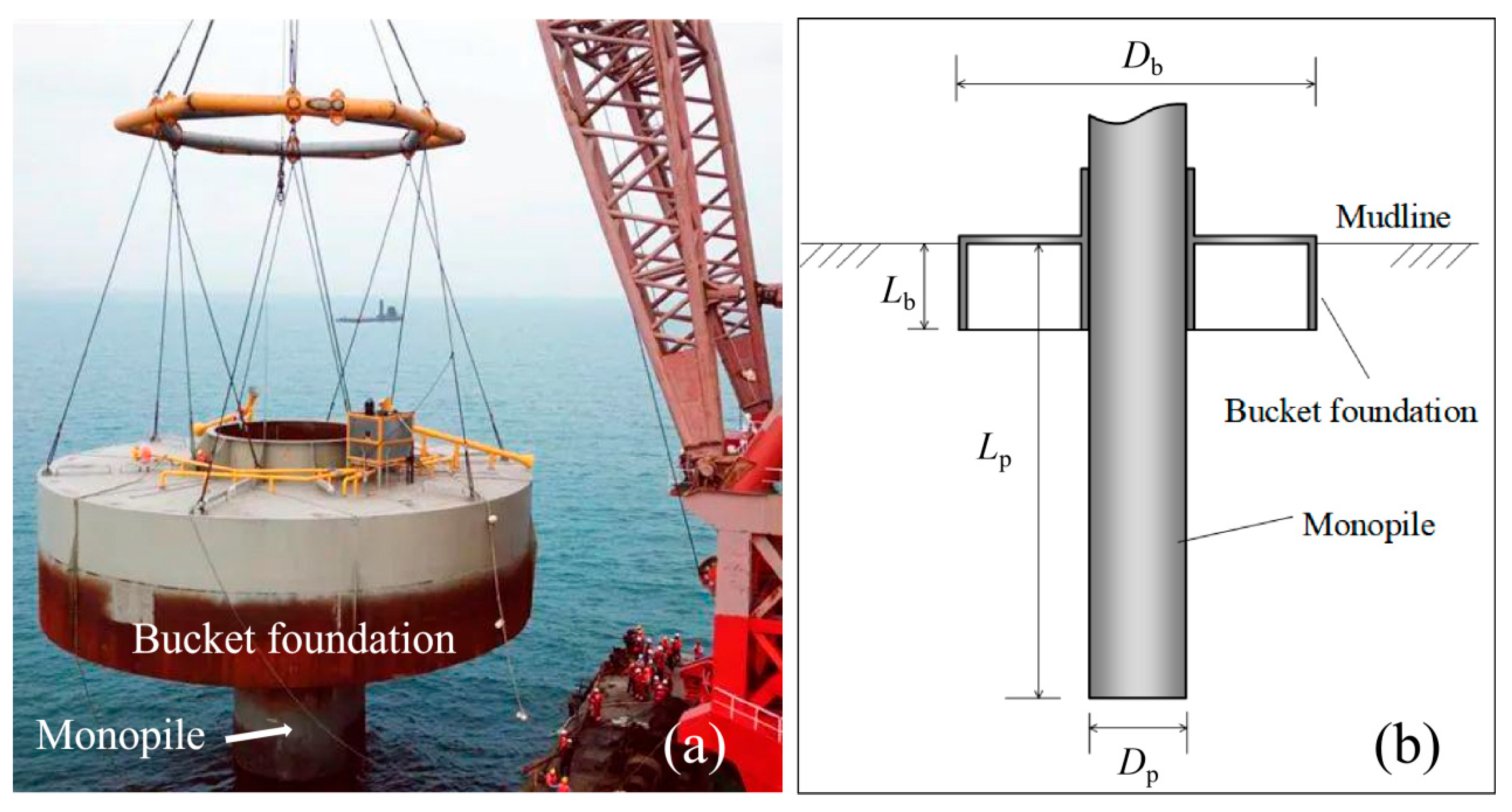
The pile–bucket concept, integrating a conventional monopile with a shallow embedded bucket foundation, as shown in Figure 1, offers a promising alternative for supporting the next-generation offshore wind turbines (OWTs) [1,2,3]. Such a hybrid structure could help mobilize additional lateral resistance from shallow soils, yielding improved horizontal load-bearing characteristics relative to monopile alone [4,5]. Since the first installation of pile–bucket foundation in 2020, it has been successfully installed in several wind farms in China, proving its potential in complex marine conditions, such as soft clay and seabeds with shallow overburden [6,7,8].
Figure 1.
Structure of pile–bucket foundation: (a) prototype [3]; (b) sketch map.
For OWT foundations, the lateral bearing characteristic is the key design factor [9,10,11]. He et al. [2] performed 1 g model tests on the load-bearing capacities of pile–bucket foundations in soft clay. Physical tests indicated that the application of a bucket at shallow depth led to around 20 times improvement in the ultimate soil reaction force compared to that of the monopile. Chen et al. [12] conducted 3D finite element modeling on the seismic performance of the pile–bucket foundation and found that the bucket carried most of the lateral load and the monopile foundation resisted most of the overturning moment. Li et al. [4] analyzed the interaction between the pile–bucket foundation and the soil via a 3D coupled discrete-continuum approach and revealed that the soil plug inside the bucket displaced simultaneously with the overall structure. Li et al. [5] also considered the influence of the grouted connection and the influence of grout parameters on the bearing performance of the pile–bucket foundation. For the calculation method, Ouyang et al. [1,13] and Liu et al. [14] proposed modified p-y models for pile–bucket foundations based on numerical tests and large-scale model tests. Considering the rigid-rotation behavior of pile–bucket foundations, Chen et al. [15] constructed an analytical framework based on the limit analysis theory and proved its validity against experimental results.
The above research provides valuable knowledge on the bearing characteristics of pile–bucket foundations; however, it underscores the importance of accounting for soil layer heterogeneity, especially for the composite strata [16,17]. It has been proved that the bearing mechanism of a shallow foundation in layered strata differs markedly from that in uniform soil deposits such as pure sand or clay [18]. Zou et al. [19] conducted a systematic experimental study and numerical simulation on the static bearing response of the pile–bucket foundation in layered sand–clay strata and concluded that the effect of increasing the bucket diameter and sand layer thickness was the most significant. Chen et al. [20] considered the combined influence of scour effects and layered strata on the lateral bearing capacity of the pile-plated composite foundation and found that the soil resistance differed remarkably as the soil deposits changed. However, insufficient research has focused on the bearing response of pile–bucket foundations in layered strata, leading to inconsistency in their design and construction in field conditions.
The objective of this study is to investigate the lateral bearing characteristics of the pile–bucket foundation in sand-overlying-clay strata and propose a corresponding calculation method. Systematic numerical simulations were first conducted to analyze the influence of foundation geometry and Hs/Hc on the lateral load-bearing response of the pile–bucket foundation. Then, p-y models are introduced and modified to predict the lateral bearing response.
2. Numerical Modeling Approach
2.1. Model Construction
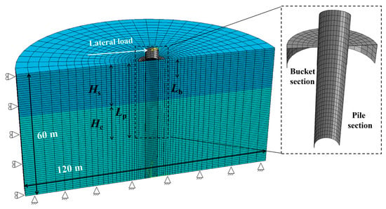
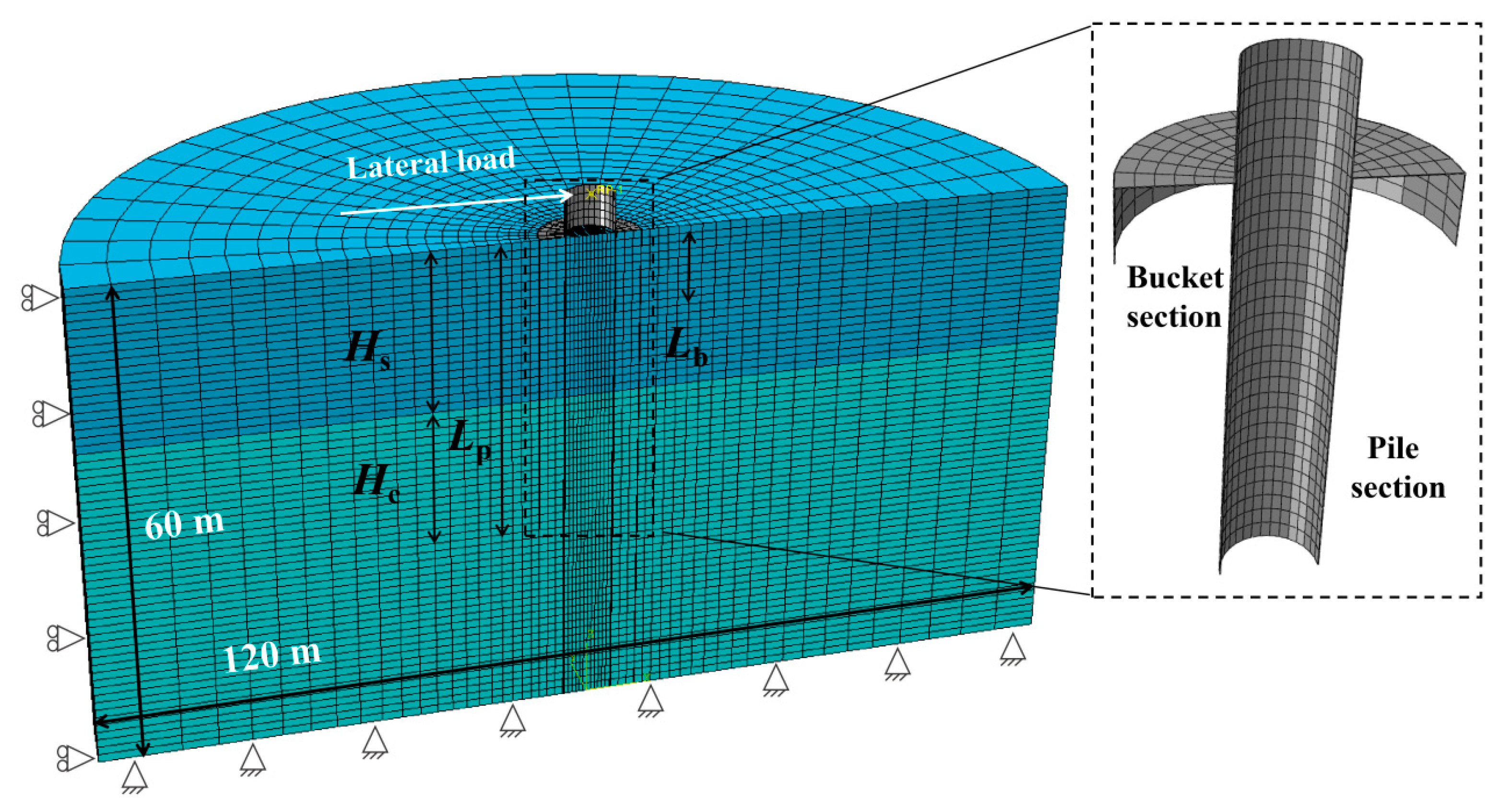
Numerical simulation of the static lateral load tests on the pile–bucket foundation in layered sand–clay strata is conducted based on the commercial finite element software ABAQUS (Version 2022) [21,22]. Taking into account the symmetry of the structure and its bearing behavior, only half of the pile–bucket structure and the soil deposits are established to save computation cost, as shown in Figure 2 [23,24]. The pile diameter and embedded depth are represented as Dp and Lp, the bucket diameter and embedded depth are represented as Db and Lb, and the thickness of the upper and lower sand layers are represented as Hs and Hc. A total of thirty model configurations are simulated considering the variance of pile and bucket geometry and sand/clay thickness ratio, as shown in Table 1. A typical model configuration is Dp = 6 m, Lp = 30 m. The soil domain extends to a depth of 60 m and a width of 120 m. This leads to a distance from the pile shaft to the soil boundary of around 10 Dp and a distance from the pile tip to the soil boundary of around 5 Dp. Although the bucket provides an extra boundary, the influence is limited to shallow depth, and the boundary effect could be neglected in the above dimensions according to similar simulations [25,26]. Regarding the boundary constraints, the base of the soil domain is fully restrained, and displacements normal to the symmetry plane are set to zero; the lateral boundary movements are restricted in the x and y-directions.
Figure 2.
Configuration of the numerical model.
Table 1.
Summary of lateral load tests on the pile–bucket foundation (unit: m).
The pile–bucket foundation and the surrounding soil are meshed using the 8-node linear brick elements with reduced integration (C3D8R). Refined meshes are employed in the region surrounding the pile–bucket foundation, whereas coarser meshes are utilized in regions away from the structure, as shown in Figure 2. Regarding the contact conditions, the pile and the bucket foundation are fully connected, and no slippage is allowed. For soil–structure contact, the surface-to-surface contact algorithm is applied, where detachment and sliding are allowed. The pile–bucket foundation is designated as the master body and the surrounding soil as the slave. The normal direction of the interface is modeled as a non-penetration constraint (hard contact), whereas the tangential slip behavior is regulated through a penalty formulation with an interface friction coefficient of 0.5.
2.2. Parameter Selection
The pile–bucket foundation is simulated as an ideal elastic material, i.e., Q345 steel, with a yield strength of 345 MPa, Young’s modulus of 2.06 × 10⁹ N/m2, density of 7850 kg/m3, and Poisson’s ratio of 0.3. The von Mises yield criterion is applied to describe the constitutive characteristics of the Q345 steel. For the soil constitutive model, the Mohr–Columb criterion is adopted. The sand parameters are as follows: density is 980 kg/m3, Young’s modulus is 20 MPa, Poisson’s ratio is 0.3, friction angle is 31°, and dilation angle is 3°. For the clay parameters, the density is set as 800 kg/m3, Poisson’s ratio is 0.495, Young’s modulus is 11.8 MPa, and the undrained shear strength is assumed to vary linearly with depth as
where Su0 is the undrained shear strength at the clay surface, and kz is the gradient of shear strength with depth, which is taken as 1.75 kPa/m.
Su = Su0 + kzz
For all the numerical tests, a static lateral load is applied in a displacement-controlled manner on the reference point at the pile head, with a load eccentricity of 5 m. In this simulation, the installation process is ignored, and the pile–bucket foundation is ‘wished-in-place’ in the soil [27,28]. This is a common approach in both model tests and numerical simulation to avoid the installation disturbance on the bearing response of the foundation. After installation, the initial geostress is balanced until the vertical displacement is less than 10−4 m and the lateral load tests start.
2.3. Model Validation
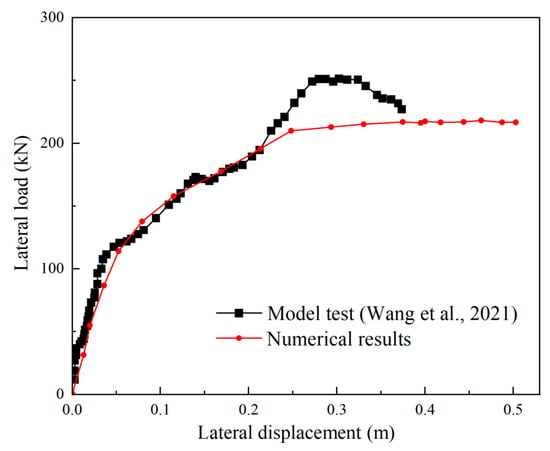
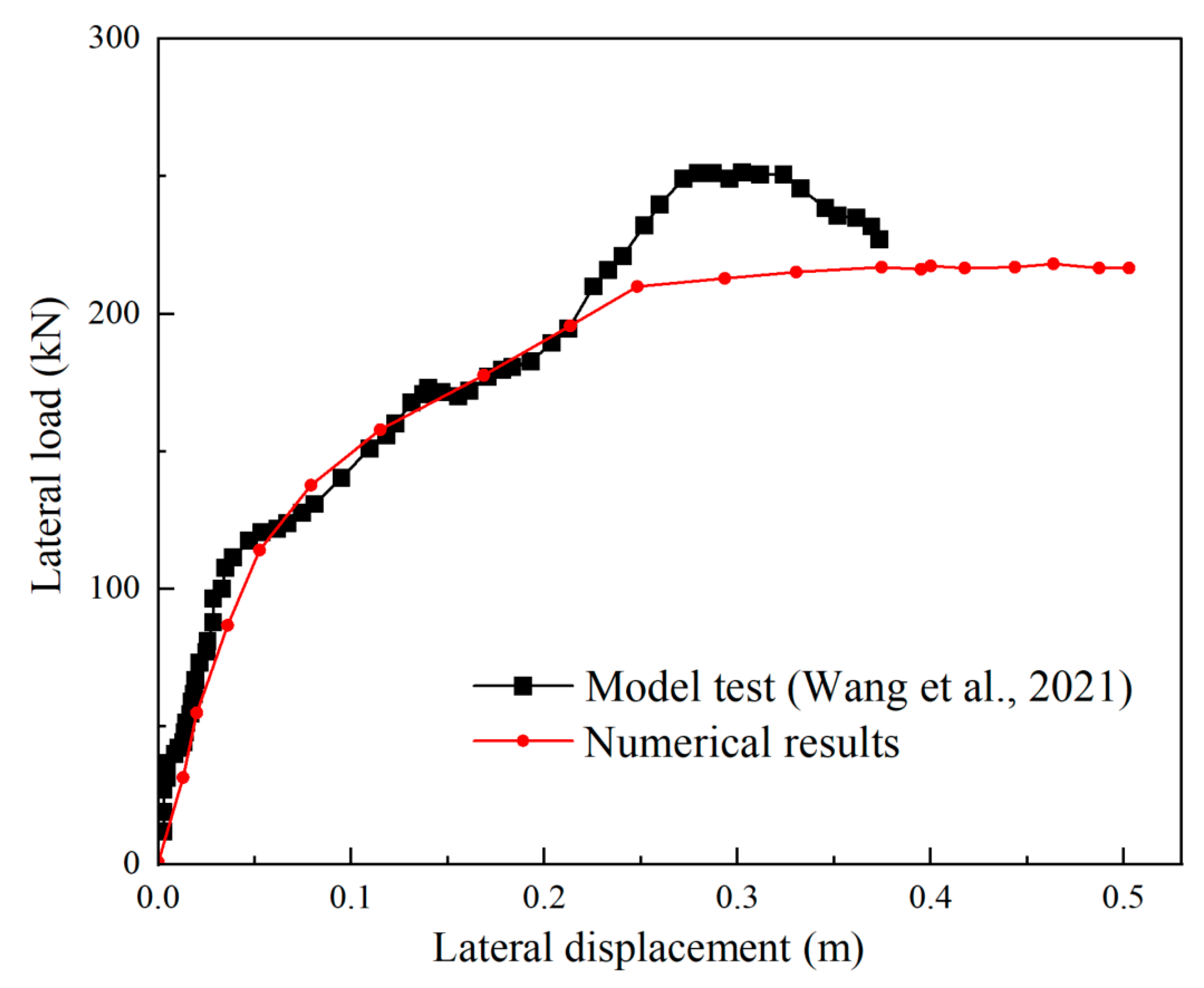
In this section, the validity of the above numerical model and input parameters is checked against centrifuge test results, where static lateral load tests on a model pile–bucket foundation installed in pure sand were performed [28]. The numerical model size is adjusted to the prototype size according to the centrifuge test, and the lateral load–displacement curves are extracted and plotted in Figure 3. It can be seen that the numerical model could provide reasonable predictions of the lateral load response, in terms of both magnitude and trend. Hence, the above numerical model is deemed suitable for subsequent investigation of the lateral bearing response of the pile–bucket foundation.
Figure 3.
Comparison of numerical and model test results [28].
3. Lateral Bearing Characteristics of the Pile–Bucket Foundation
In this section, the influence of sand/clay thickness ratio and foundation geometry on the lateral bearing characteristics of the pile–bucket foundation is investigated.
3.1. Influence of Hs/Hc
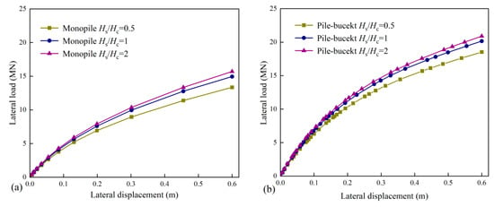
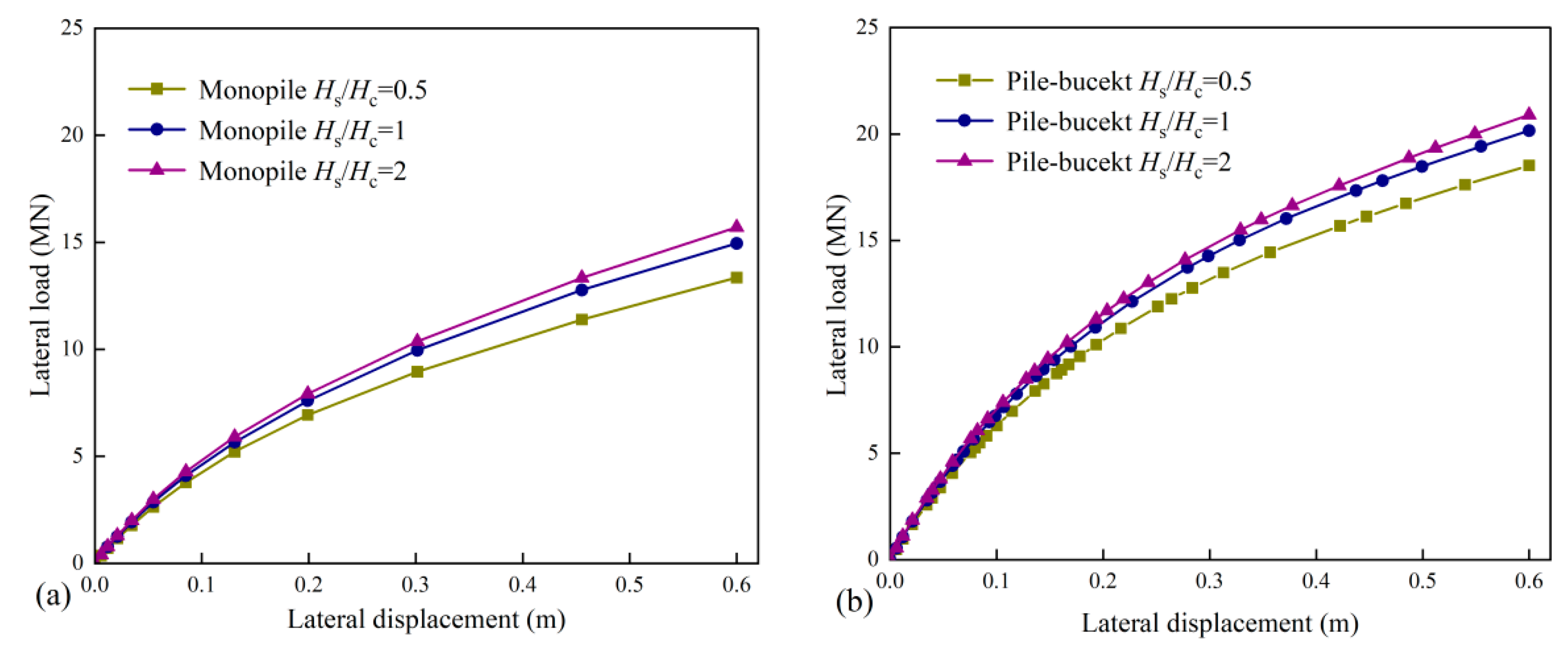
The influence of sand/clay thickness ratio (Hs/Hc) is first studied. For clarification, the thickness of the soil layer is limited to 30 m, which equals the pile embedded depth in a typical numerical model configuration. For example, when Hs/Hc is 0.5, the sand layer thickness is 10 m, and the clay layer thickness used for comparison is 20 m (the actual clay thickness in the soil domain is 50 m). The load–displacement curves from Test 1~3 and three monopile models in the same soil profiles are extracted and plotted in Figure 4. It is clear that the addition of a bucket improves the overall bearing capacity. The bearing capacity of both the monopile and pile–bucket foundation increases as the upper sand layer thickness increases, especially when Hs/Hc increases from 0.5 to 1.
Figure 4.
Lateral load–displacement curves with different Hs/Hc: (a) monopile; (b) pile–bucket foundation.
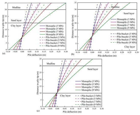
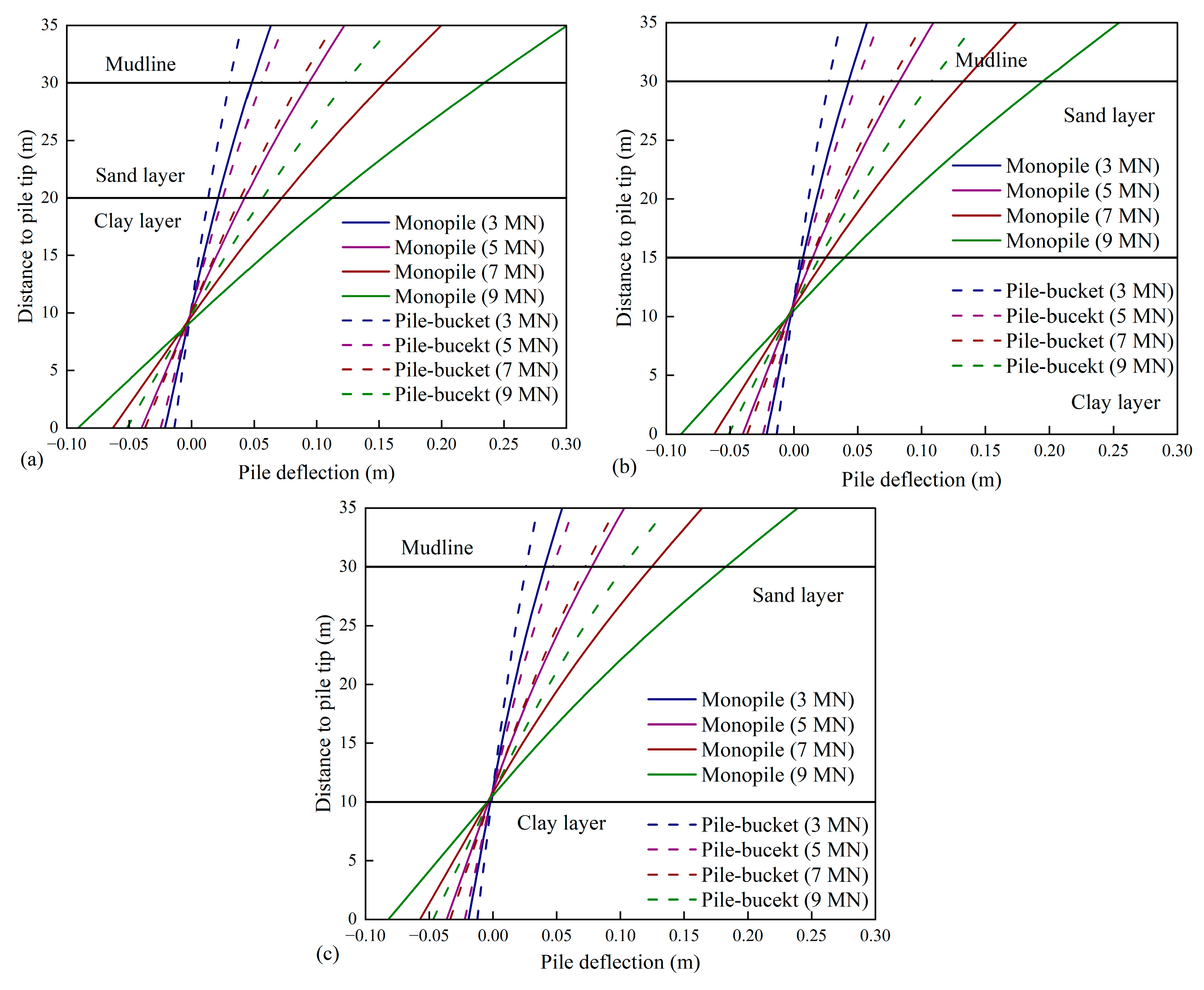
Then, the pile shaft displacement for the above numerical models at different load levels is extracted. As shown in Figure 5, the addition of a bucket helps control the lateral displacement of the pile shaft. Both the monopile and the pile–bucket foundation seem to move like a rigid body with a fixed rotation center. As the sand layer thickness increases, the enhancing effect of the bucket in controlling the lateral displacement is more obvious, especially when Hs/Hc increases to 1. The position of the rotation center also lifts with increasing sand layer thickness. This is due to the fact that the sand layer could provide higher bearing resistance compared to clay. As a result, increasing resistance would be mobilized in shallow soil, and consequently induce an upward migration of the rotational center. However, the enhancing effect is less obvious as Hs/Hc exceeds 1. This will be discussed in the following sections.
Figure 5.
Comparison of pile deflection at different load levels: (a) Hs/Hc = 0.5; (b) Hs/Hc = 1; (c) Hs/Hc = 2.
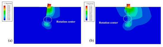
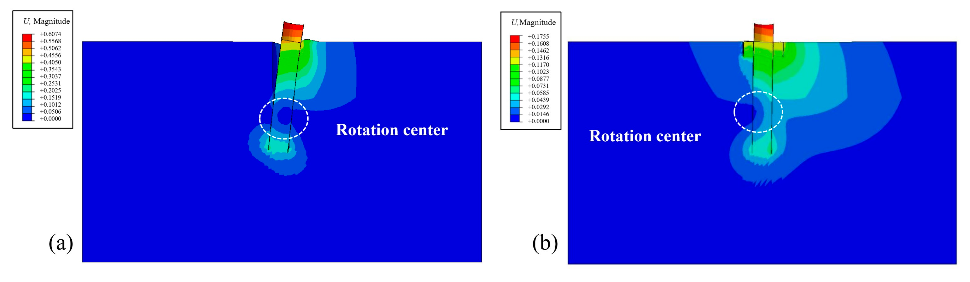
The bearing characteristics of the pile–bucket foundation in the layered sand–clay strata are investigated by plotting the soil displacement contour and the vector contour at Hs/Hc of 2. As shown in Figure 6, the monopile and the pile–bucket foundation show similar bearing mechanisms under static lateral load, with a typical rigid rotational failure pattern. For the monopile foundation, soil heave occurs at the loading side due to pile compression, and detachment can be observed at the opposite side. For the pile-bucket foundation, the soil displacement is smaller but with a larger influence area. Soil displacement mainly occurs in the shallow sand layer and at the pile tip in the clay layer, while no distinct soil displacement occurs at the sand–clay interface. Compared with pure sand or clay soil deposits, the sand-overlying-clay deposit has no direct influence on the bearing mechanism of either foundation under static lateral load.
Figure 6.
Soil displacement contour around (a) monopile foundation; (b) pile–bucket foundation.
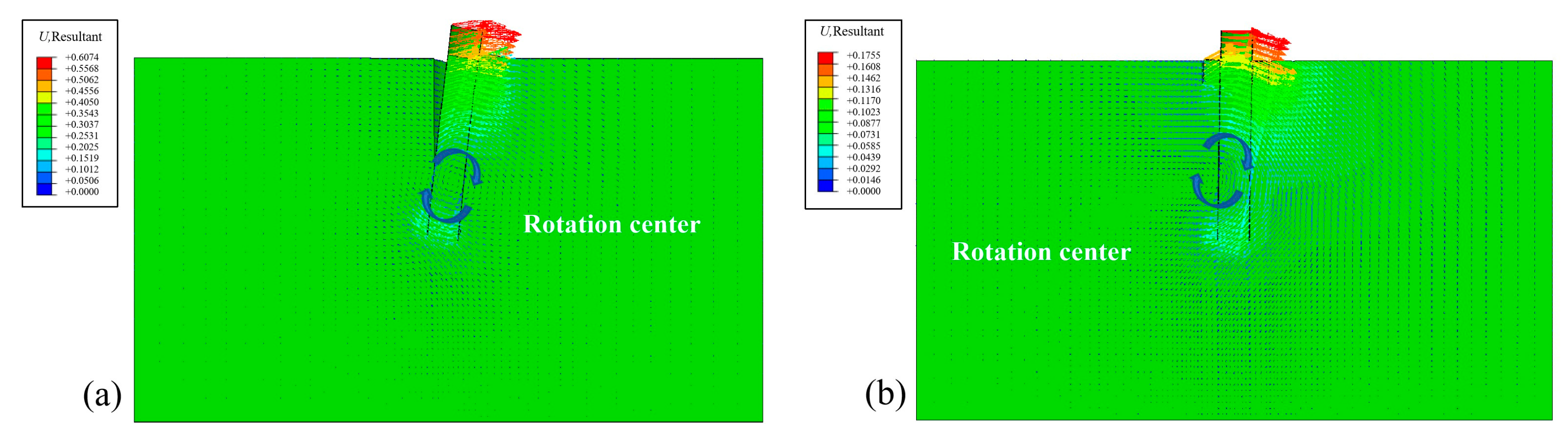
The soil displacement vector around the monopile and pile–bucket foundation is further plotted in Figure 7. For the monopile foundation, the displacement vector mainly concentrates around the pile shaft. This phenomenon is consistent with the fact that most of the external load is resisted by the pile shaft friction and the contribution of the deep clay is limited. For the pile–bucket foundation, the displacement vector shows obvious horizontal diffusion at the bottom and shaft of the bucket, leading to a wider shearing failure zone at shallow depth. According to the distribution of the displacement vector, the addition of the bucket expands the mobilization of soil resistance at shallow soil, leading to lower stress concentration and high stability.
Figure 7.
Soil displacement vector around (a) monopile foundation; (b) pile–bucket foundation.
3.2. Influence of Pile–Bucket Geometry
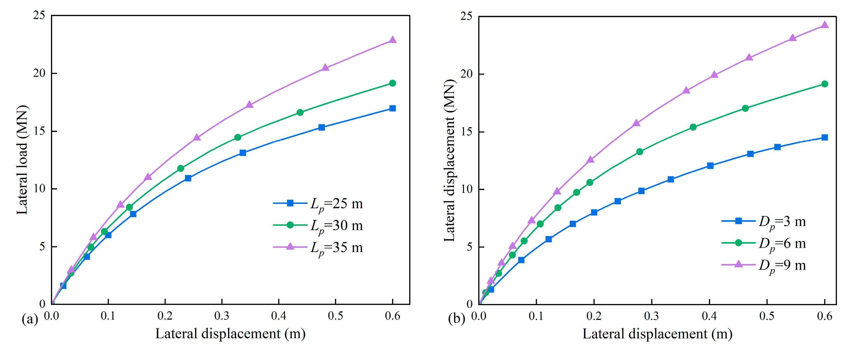
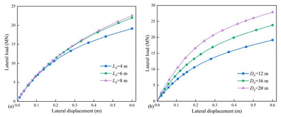
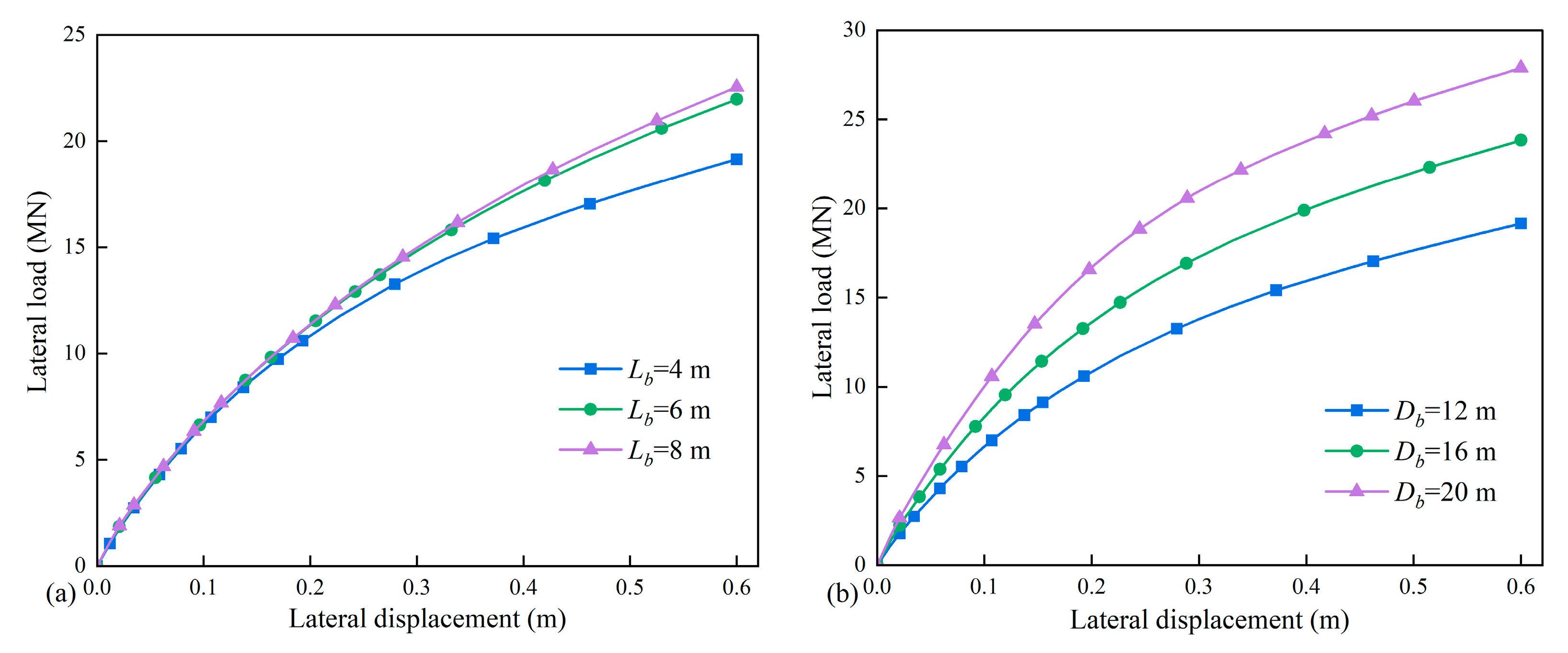
In this section, the influence of pile–bucket geometry at Hs/Hc of 1 is studied. The load–displacement curves of pile–bucket foundations with different pile embedded depths and pile diameters are first plotted. As shown in Figure 8, the increase in pile size leads to an increase in bearing capacity. The beneficial effect is more obvious when increasing the bucket diameter. A similar phenomenon can be observed in Figure 9, where the increase in bucket diameter leads to a larger capacity improvement. Meanwhile, the enhancing effect is limited as the bucket length exceeds 6 m.
Figure 8.
Lateral load–displacement curves considering the influence of (a) pile embedded length; (b) pile diameter.
Figure 9.
Lateral load–displacement curves considering the influence of (a) bucket length; (b) bucket diameter.
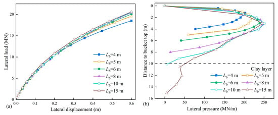
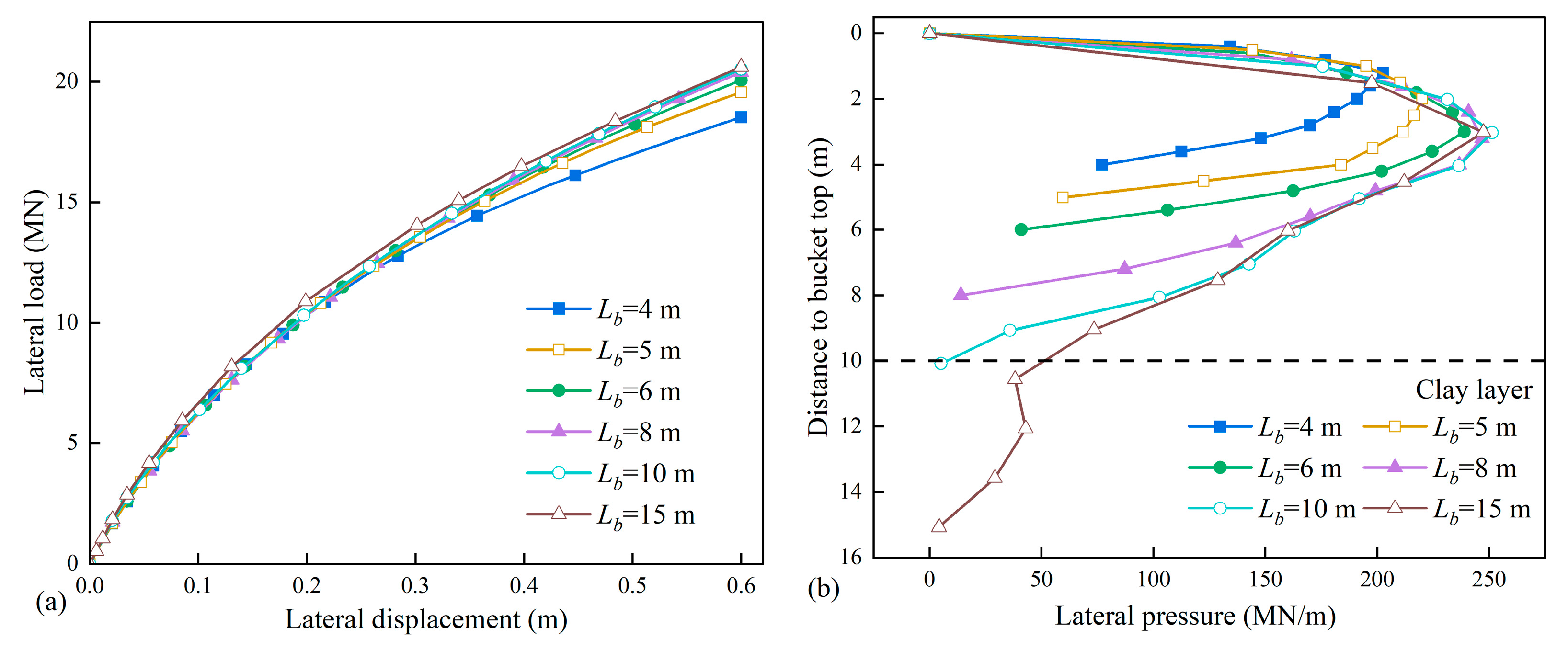
For the above numerical cases, the bucket length does not exceed the sand layer thickness. Considering the field situation where the bucket may penetrate into the lower clay layer, the bearing characteristics of pile–bucket foundations with different bucket lengths embedded in a 10 m sand layer are studied. As shown in Figure 10a, the bearing capacity increases with increasing bucket length; as the bucket length exceeds around half of the pile length, the enhancing effect is less obvious and can be neglected as the bucket tip penetrates the sand layer. The characteristics of bearing capacity development can be explained by the distribution of lateral pressure along the bucket shaft. As shown in Figure 10b, the upper section of the lateral pressure curves, which covers most of the soil pressure of the bucket, basically coincides as the bucket length exceeds half of the sand layer thickness. It can be seen that the bearing efficiency of the bucket gets lower as the bucket lip approaches the clay layer. As a result, the bucket length should be limited to the sand layer thickness to achieve higher bearing efficiency.
Figure 10.
Influence of bucket length: (a) load–displacement curve; (b) distribution of lateral pressure.
4. Construction of the p-y Model for Pile–Bucket Foundation
The p-y curve approach, which treats the pile as a beam resting on nonlinear soil springs, is recognized as the most prevalent design methodology for laterally loaded pile foundations. In the p-y model, p is defined as the lateral soil reaction per unit pile length and y is the associated lateral pile deflection at a given depth [29]. In this section, the p-y response for the pile–bucket foundation in layered sand–clay strata is further analyzed. According to the above analysis, the bucket section should be embedded in the sand layer to produce higher bearing efficiency. Thus, the soil condition is set as Hs/Hc of 1, and the bucket is fully embedded in the sand layer. Accordingly, the pile–bucket foundation is divided into three sections: bucket section, pile section in the sand layer, and pile section in the clay layer.
4.1. Parametric Analysis
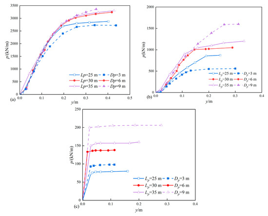
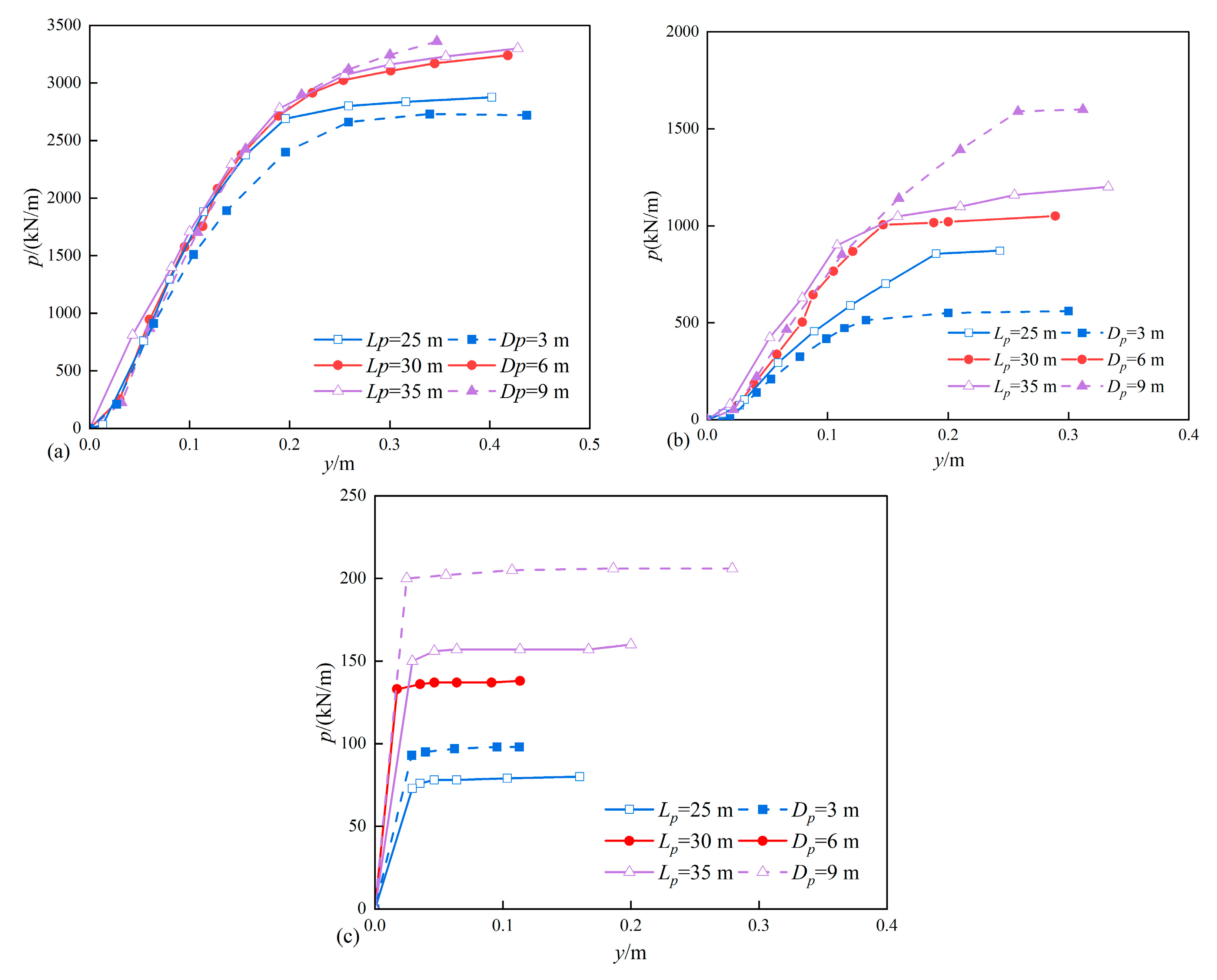
The influence of pile diameter and embedded length is analyzed by extracting p-y curves from Tests 2, 5, 8, 11, and 14 at depths of 2 m, 10 m, and 20 m, which represent the bucket section, pile section in the sand layer, and pile section in the clay layer. The initial stiffness (ki) and the ultimate lateral resistance (pu) are selected to characterize the p-y curves. As shown in Figure 11, the initial stiffness of the p-y curves at the bucket section is unaffected by the variance of pile geometry. Although the ultimate lateral resistance increases with increasing pile size, the influence is limited as the embedded length exceeds 30 m and the diameter exceeds 6 m. For the pile section in the sand layer, the influence of the pile embedded length is limited, and the pile diameter is the controlling factor. For p-y curves at deeper positions, namely the pile section in the clay layer, the magnitude of lateral resistance decreases significantly; however, the pile diameter remains the controlling factor for both initial stiffness and ultimate lateral resistance.
Figure 11.
Influence of pile parameters on p-y curves at depths of (a) 2 m; (b) 10 m; (c) 20 m.
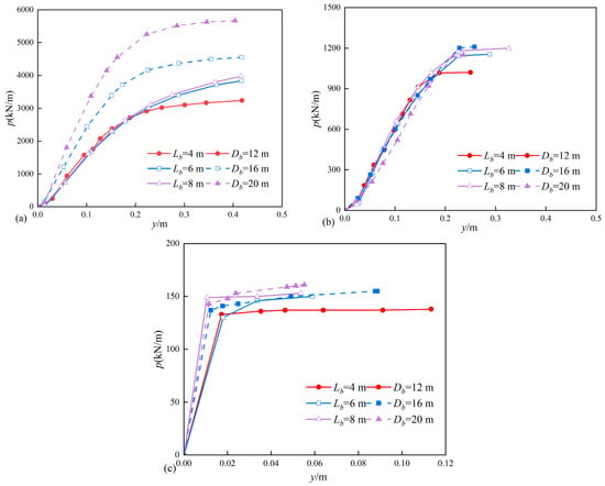
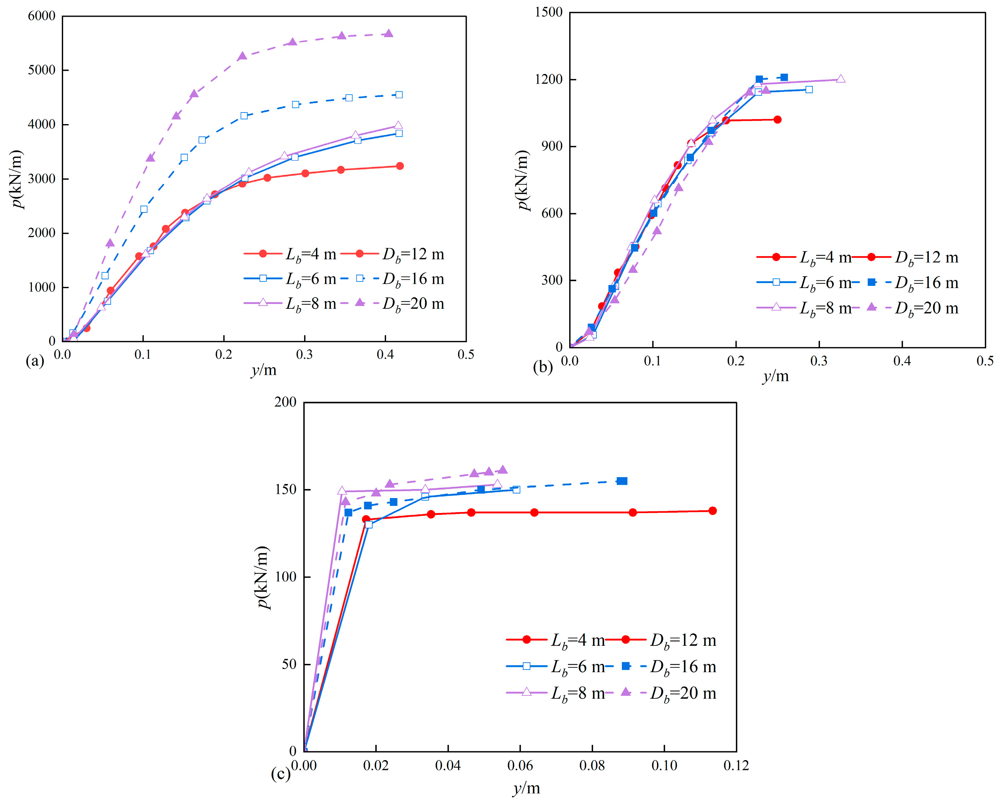
The p-y curves at the above three depths for Tests 2, 17, 20, 23, and 26 are plotted in Figure 12 to analyze the influence of bucket diameter. For p-y curves at the bucket section, the increase in bucket diameter leads to a notable increase in both the initial stiffness and the ultimate lateral resistance, while the influence of the bucket is limited. At the pile section, the p-y curves are not influenced by the variation in bucket parameters, regardless of the soil property.
Figure 12.
Influence of bucket parameters on p-y curves at a depth of (a) 2 m; (b) 10 m; (c) 20 m.
4.2. Model Construction and Modification
The most widely used formulas for p-y curves can be classified into two categories: power function form and hyperbolic form [30]. In this section, the hyperbolic p-y model is applied to delineate the bearing characteristics of the pile–bucket foundation. The hyperbolic p-y model includes two critical parameters: the initial stiffness and the ultimate resistance.
where k1 is the initial stiffness and pu is the ultimate resistance.
The p-y model at the pile section of the pile–bucket foundation is first modified. According to the above analysis, the p-y response at the pile section is basically unaffected by the bucket parameter. As a result, the modification approach for p-y curves of monopile foundation can be used as a reference. For the ultimate resistance, Equation (3) and Equation (4) can be applied in sand and clay layers, respectively.
where C1, C2, and C3 are ultimate resistance coefficients, which are related to the soil internal friction angle.
For the initial stiffness, Carter [31] proposed an empirical approach that considers the pile size effect as follows:
where Es is the soil elastic modulus, μs is Poisson’s ratio, d is the pile/bucket diameter, dref is the reference diameter, with a recommended value of 1.0 m, and EpIp is the pile flexural rigidity.
Liang et al. [32] found that Carter’s empirical equation contradicted the numerical result and proposed a generalized function to modify Equation (5). Two coefficients, namely i and j, which represent the influence of size effect and environment effect, are introduced as follows:
A logarithmic transformation of Equation (6) is performed, which is further transformed into a linear equation, as shown in Equation (7).
where X is logEsd4/Eplp, Y is logKi(1 − μs2)dref/Esd.
Then, the linear equation is fitted with data sets from the above numerical model to obtain the correction coefficients. The modified initial stiffness for p-y curves in sand and clay layers can be rewritten as follows:
For p-y curves at the bucket section, the modified approach for initial stiffness could be directly applied by substituting the bucket diameter, while the ultimate resistance should be modified considering the influence of the bucket’s diameter. Guo and Zhu [33] proposed a generalized limiting force approach to predict the ultimate resistance for pile foundation embedded in sand:
where Ng is the limiting force factor, which takes the value of Kp2 (Kp is the passive pressure coefficient); z is the depth below the ground surface; n is the shape factor that controls the distribution of ultimate resistance; α0 is the dimensionless factor that characterizes the ultimate resistance.
To modify the ultimate resistance at the bucket section, the calculated value from Equation (10) and the numerical results are compared and fitted to obtain the corresponding n and α0 values. Bagheri et al. [34] suggested that the shape factor n could be linearly correlated with the bucket diameter and the ultimate resistance factor α0 could be linearly correlated with the bucket aspect ratio (Db/Lb). As a result, the functions for the two factors considering the bucket size effect are linearly fitted and obtained as follows:
4.3. Calculation Method and Validation
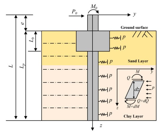
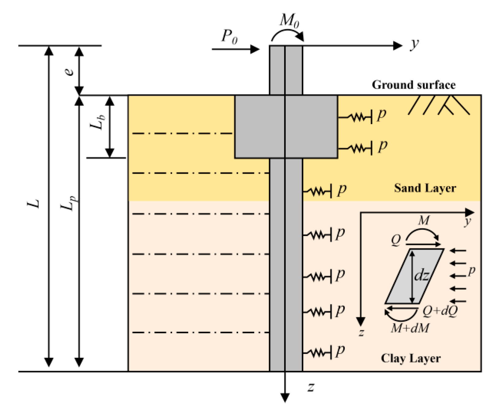
The above analysis provides a modified p-y model to describe the soil–structure interaction at different depths. In this section, the finite difference method is applied to discretize the pile–bucket foundation into a series of nodes, and the iterative procedure is introduced to achieve the calculation. Based on the equilibrium equation of the pile–bucket element and the boundary condition, the deflection of the structure, the bending moment, shear force, and rotation angle at each point can be calculated using the modified p-y model, as shown in Figure 13. Detailed information on the programming procedure of the calculation process is provided by Liu et al. [14].
Figure 13.
Schematic diagram of the force equilibrium state of the pile–bucket foundation.
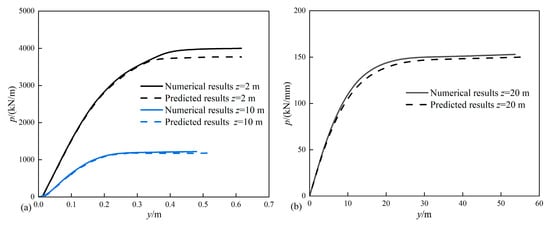
Based on the above procedure, the performance of the modified p-y model is validated. The predicted results are compared with numerical results from T17. p-y curves at three typical depths, 2 m, 10 m, and 20 m, are extracted, which represent the bucket section, pile section in the sand layer, and pile section in the clay layer, respectively. As shown in Figure 14, the modified p-y model produces accurate predictions in both the sand layer and the clay layer, especially at the bucket section.
Figure 14.
Comparison of p-y curves in the (a) sand layer; (b) clay layer.
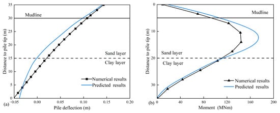
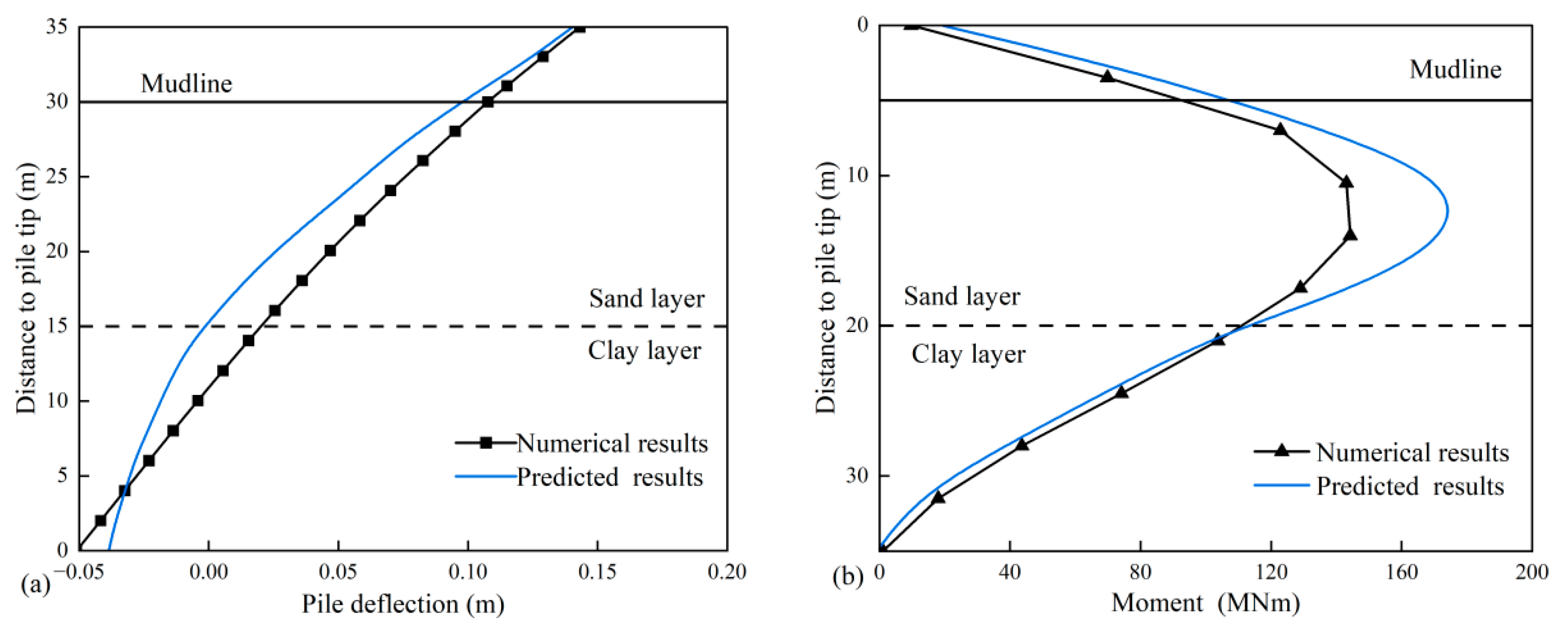
Then the overall bearing response of the pile–bucket foundation is calculated using the finite difference program and compared with the numerical results from Test 2. The pile shaft deflection at a lateral load of 9 MN and the moment distribution at pile head displacement of 0.6 m are extracted, as shown in Figure 15. The trend of predicted pile shaft deflection shows good consistency with the numerical results. However, a fluctuation occurs at the sand–clay interface. This may be because the p-y models in the sand and clay layers are modified separately. The trend of predicted moment distribution along the pile shaft also shows good consistency with the numerical results, while the predicted maximum moment is larger than the numerical results. Though the above validation of the proposed method was conducted when the bucket is fully embedded in the sand layer, the proposed p-y model could still be applied when the bucket penetrates into the soil, and further modifications are recommended for multi-layer soil deposits.
Figure 15.
Comparison of numerical results and modified p-y model: (a) pile deflection; (b) moment distribution.
5. Conclusions and Outlook
In this paper, the static lateral bearing characteristics of the pile–bucket foundation embedded in sand-overlying-clay strata are investigated via 3D FEM. Modified p-y curves that consider the bucket size effect and the influence of Hs/Hc are constructed and validated against numerical results. The main conclusions are drawn as follows:
1. According to the pile shaft deflection and soil displacement contours, a rotational failure pattern is assumed for the pile–bucket foundation under static lateral load. The addition of a bucket expands the mobilization of soil resistance in shallow soil, leading to lower stress concentration and higher stability.
2. The increase in sand layer thickness leads to increased bearing capacity and uplift of the rotation center. However, it has no direct influence on the failure pattern of the pile–bucket foundation. As Hs/Hc exceeds 1, the efficiency of increasing sand layer thickness to improve bearing capacity is no longer obvious.
3. The bearing capacity increases with increasing foundation size. However, the enhancing effect of increasing bucket length is limited, especially when the bucket length exceeds half of the sand layer thickness. It is recommended that the bucket should be embedded in the sand layer to achieve higher bearing efficiency.
4. The bucket diameter and pile diameter are found to be the controlling factors of the p-y curves of the pile–bucket foundation, which can be divided into the bucket section, pile section in the sand layer, and pile section in the clay layer. The hyperbolic p-y models for the pile–bucket foundations are further constructed by modifying the initial stiffness and ultimate lateral resistance.
Despite the above conclusions, the proposed method has several limitations that need to be addressed. The first is the ignorance of the installation effect of the pile–bucket foundation. Though the ‘wished-in-place’ approach has been widely used for the bearing analysis of monopiles, the installation of pile–bucket foundations involves more complicated disturbance due to their special structure, which could further influence the subsequent bearing process. Consequently, a more sophisticated numerical approach should be applied to investigate the installation disturbance of pile–bucket foundations and the influence on their bearing capacity [35,36]. Another limitation is the modification based on the p-y framework, which is derived from slender piles. As the stiffness of the pile–bucket foundation increases, the contribution of other resistance components from the pile/bucket shaft and base cannot be ignored, and a multi-spring model that considers the bearing mechanism of the supplemented bucket should be proposed [21,37].
Author Contributions
G.X.: software, formal analysis, writing—original draft. Q.Z.: software, formal analysis, data curation. P.G.: formal analysis, data curation. Y.Y.: formal analysis, data curation. L.L.: project administration, funding acquisition, conceptualization, review and editing. B.H.: software, formal analysis. L.W.: formal analysis, data curation. All authors have read and agreed to the published version of the manuscript.
Funding
This research is supported by the National Natural Science Foundation of China (Grant Nos. 52671348, 52308383, 52271294, W2521151). The Guangdong Basic and Applied Basic Research Foundation (Grant Nos. 2024A1515240075) and the Pioneer and Leading Goose R&D Program of Zhejiang (Grant No 2024C03031) are also acknowledged.
Data Availability Statement
Data will be made available on request.
Conflicts of Interest
Authors Gen Xiong, Peng Gao, Yancheng Yu, and Ben He are employed by the company Power China Huadong Engineering Corporation Limited. The remaining authors declare that the research was conducted in the absence of any commercial or financial relationships that could be construed as potential conflicts of interest.
References
- OuYang, H.R.; Gong, Z.Y.; Dai, C.L. Large-scale model tests of monotonic response of lateral loaded hybrid pile-bucket foundation in unsaturated clay. Acta Geotech. 2025, 20, 6001–6032. [Google Scholar] [CrossRef] [Scilit]
- He, B.; Yuan, Z.Y.; Jiang, Z.Q.; Ni, D.Y.; Shi, L.; Yuan, Z.H.; Sun, H.L. Model tests on horizontal load-bearing and deformation resistance capacities of pile-bucket foundation in soft seabed soil. Mar. Georesour. Geotechnol. 2021, 40, 1193–1204. [Google Scholar] [CrossRef] [Scilit]
- Shi, L.; Yuan, Z.Y.; Yuan, Z.H.; Sun, H.L.; Cai, Y.Q. On load-bearing and soil-reacting characteristics of hybrid pile-bucket foundations subjected to static horizontal loading. Mar. Struct. 2022, 84, 103222. [Google Scholar] [CrossRef] [Scilit]
- Li, L.C.; Zheng, M.Y.; Liu, X.; Wu, W.B.; Liu, H.; El Naggar, M.H.; Jiang, G.S. Numerical analysis of the cyclic loading behavior of monopile and hybrid pile foundation. Comput. Geotech. 2022, 144, 104635. [Google Scholar] [CrossRef] [Scilit]
- Li, L.C.; Yan, N.X.; Liu, Z.; Wu, W.B.; Jiang, G.S. Investigation on the cyclic laterally-loaded response of pile-bucket foundation with grouted connection. Mar. Struct. 2025, 103, 103808. [Google Scholar] [CrossRef] [Scilit]
- Liu, H.; Gao, Y.; Dong, X.; Zhang, Y.; Liu, X.; Zhang, Z.; El Naggar, M.H.; Wu, W.B. Unified rigorous solution for kinematic response of pipe piles embedded in unsaturated soil subjected to S waves. Int. J. Numer. Anal. Methods Geomech. 2026, 50, 5462–5478. [Google Scholar] [CrossRef] [Scilit]
- Wu, W.B.; Di, T.Y.; Zhang, Y.P.; Liu, H. Revised pile-pile mutual interaction factors for seismic analysis of end-bearing pile groups embedded in saturated stratum. Soil Dyn. Earthq. Eng. 2024, 183, 108745. [Google Scholar] [CrossRef] [Scilit]
- Cheng, X.L.; Chong, Z.; Liang, J.Y. Dynamic response of offshore wind turbine supported by suction bucket in sands under multi-hazard loads considering the scour-hole dimensions. Soil Dyn. Earthq. Eng. 2026, 209, 110430. [Google Scholar] [CrossRef] [Scilit]
- Yao, Z.S.; Wang, H.; Melville, B.W.; Sumer, B.M.; Guan, D.W. Unified prediction equation for equilibrium scour depth around vibrating monopile foundations. Coast. Eng. 2026, 208, 105006. [Google Scholar] [CrossRef] [Scilit]
- Zhan, C.H.; Liu, H.; Ye, J.L.; Wan, C.B.; Luo, R.Q.; Xu, M.J.; Zhang, Y.P.; Wu, W.B. Analytical solution for longitudinal vibration of end-bearing pipe pile groups in arbitrary layered soil considering wave scattering effect. Appl. Math. Model. 2026, 158, 116980. [Google Scholar] [CrossRef] [Scilit]
- Zhan, C.H.; Wang, B.; Han, G.; Liu, H.; Li, B.; Liu, X.; Zhang, Y.P.; Wu, W.B. Analytical solution for the vertical vibration of an end-bearing pipe pile group with defective piles in stratified soil. Ocean Eng. 2026, 359, 125910. [Google Scholar] [CrossRef] [Scilit]
- Chen, W.Y.; Jiang, Y.J.; Xu, L.Y.; Liu, C.; Chen, G.X.; Wang, P.G. Seismic response of hybrid pile-bucket foundation supported offshore wind turbines located in liquefiable soils. Ocean Eng. 2023, 269, 113519. [Google Scholar] [CrossRef] [Scilit]
- Ouyang, H.R.; Gong, Z.Y.; Dai, C.L. A simplified calculation method of the lateral response of monopiles in clay with constant or linearly increasing soil strength. Ocean Eng. 2026, 359, 125962. [Google Scholar] [CrossRef] [Scilit]
- Liu, R.; Shi, J.Y.; Chen, G.S.; Yang, X. Lateral bearing capacity and calculation method of pile-bucket foundation in clay for offshore wind turbines. Ocean Eng. 2023, 283, 115039. [Google Scholar] [CrossRef] [Scilit]
- Chen, G.S.; Du, W.C.; Liu, R.; Li, C.F. Upper Bound Solution of Maximum Horizontal Translational Ultimate Bearing Capacity of Pile-Bucket Composite Foundations for Offshore Wind Turbines. J. Mar. Sci. Appl. 2026. [Google Scholar] [CrossRef] [Scilit]
- Li, X.; Zhou, W.-H.; Liu, J.K. Elastic-plastic response and particle breakage in marine coral sand: Roles of fines and density state. Ocean Eng. 2025, 323, 120499. [Google Scholar] [CrossRef] [Scilit]
- Li, X.; Li, X.Y.; Nan, J.Y. Dilatancy behavior of marine coral sand-fines mixture in the South China Sea: Critical thresholds and particle breakage effects. Acta Geotech. 2026, 21, 4079–4099. [Google Scholar] [CrossRef] [Scilit]
- Wang, J.Y.; Liang, K.; Zhou, M.; Yang, N.X. Behavior of Shared Suction Anchors in Clay Overlying Silty Sand Soils Considering the Souring Effect. J. Mar. Sci. Eng. 2025, 13, 2394. [Google Scholar] [CrossRef] [Scilit]
- Zou, X.J.; Chen, S.; Hu, J.F.; Yang, Z.J. Capacity of monopile-bucket composite foundations in layered sand-clay strata under lateral loading. Ocean Eng. 2024, 304, 117849. [Google Scholar]
- Chen, S.; Zou, X.J.; Tu, X.Y.; Yang, Z.J.; Liang, C.X. Scours effects on the lateral bearing capacity of monopile-friction wheel composite foundations in sand-overlaying-clay deposit. Ocean Eng. 2024, 310, 119065. [Google Scholar] [CrossRef] [Scilit]
- Shao, X.; Xu, M.; Mei, G.; El Naggar, M.H.; Wu, W. Development of a p-multiplier for laterally loaded single batter piles in sand based on simple upper bound analysis. Comput. Geotech. 2025, 184, 107268. [Google Scholar] [CrossRef] [Scilit]
- Cheng, X.L.; Zhang, Z.X.; Wang, X.Y.; Yang, K.X.; Lu, D.C.; Du, X.L. Shaking table tests of four-bucket jacket foundation for offshore wind turbines in soft clay. Ocean Eng. 2026, 352, 124568. [Google Scholar] [CrossRef] [Scilit]
- Yu, X.X.; Zheng, G.; Zhou, H.Z.; Xie, G.; Zhao, J. Reliability analysis for the progressive failure ultimate limit state design in geosynthetic-reinforced rigid pile-supported embankments. Geotext. Geomembr. 2026, 54, 531–548. [Google Scholar] [CrossRef] [Scilit]
- Yu, X.X.; Xie, G.; Zhou, H.Z.; Zheng, G. Calibration of partial factors for the pile efficiency serviceability limit state design in geosynthetic-reinforced and pile-supported embankment. Can. Geotech. J. 2026, 63, 1–21. [Google Scholar] [CrossRef] [Scilit]
- Wang, L.; Zhang, L.R.; Chen, H.Z. Combined effects of anchor geometry and soil spatial variability on the probabilistic pullout capacity of helical anchors. Comput. Geotech. 2026, 200, 108482. [Google Scholar] [CrossRef] [Scilit]
- Wang, H.; Lehane, B.M.; Bransby, M.F.; Askarinejad, A.; Wang, L.Z.; Hong, Y. A simple rotational spring model for laterally loaded rigid piles in sand. Mar. Struct. 2022, 84, 103225. [Google Scholar] [CrossRef] [Scilit]
- Shao, X.; Wang, B.; Liu, L.; Huang, D.; Liu, H.; Liu, X.; El Naggar, M.H.; Wu, W.B. A unified hybrid beam model and transfer matrix solution for three novel OWT monopile foundations. Ocean Eng. 2026, 365, 127426. [Google Scholar] [CrossRef] [Scilit]
- Wang, J.Y.; Sun, G.D.; Chen, G.S.; Yang, X. Finite element analyses of improved lateral performance of monopile when combined with bucket foundation for offshore wind turbines. Appl. Ocean Res. 2021, 111, 6001–6032. [Google Scholar] [CrossRef] [Scilit]
- Li, X.Y.; Zhang, M. Soil-structure interaction of a laterally loaded hybrid foundation for offshore wind turbine. Ocean Eng. 2022, 263, 112197. [Google Scholar] [CrossRef] [Scilit]
- Li, H.J.; Lu, D.; Liu, S.Y.; Tong, L.Y.; Tamura, S. Analysis methods for soil-pile interaction of laterally loaded piles: A state-of-the-art review. Ocean Eng. 2026, 363, 126560. [Google Scholar] [CrossRef] [Scilit]
- Carter, D.P. A non-linear soil model for predicting lateral pile response. Doctoral Dissertation, University of Auckland, Auckland, New Zealand, 1984. [Google Scholar]
- Liang, R.; Shatnawi, E.S.; Nusairat, J. Hyperbolic p-y criterion for cohesive soils. Jordan J. Civ. Eng. 2007, 1, 38–58. [Google Scholar]
- Guo, W.D.; Zhu, B.T. Laterally loaded fixed-head piles in sand. In Proceedings of the 9th Australia-New Zealand Conference on Geomechanics, Auckland, New Zealand, 8–11 February 2004; Volume 1, pp. 88–94. [Google Scholar]
- Bagheri, P.; Son, S.W.; Kim, J.M. Investigation of the load-bearing capacity of suction caissons used for offshore wind turbines. Appl. Ocean Res. 2017, 67, 148–161. [Google Scholar] [CrossRef] [Scilit]
- Wang, K.P.; Cui, C.Y.; Zhang, P.; Yasufuku, N.; Xu, G.L.; Wang, M. Numerical investigation of the installation process and bearing capacity of circular helicoid piles in undrained clay. Soils Found. 2024, 64, 101411. [Google Scholar] [CrossRef] [Scilit]
- Wang, K.P.; Zhang, R.; Yasufuku, N.; Xu, G.L. Cavity expansion-based prediction methods for the uplift capacity and reaction torque of circular helicoid piles. Comput. Geotech. 2027, 201, 108536. [Google Scholar] [CrossRef] [Scilit]
- Guo, P.; Zhang, Y.; Di, T.; Qi, T.; Li, R. A macro-element model for integrated analysis of monopile-supported offshore wind turbines. Mar. Struct. 2026, 109, 104071. [Google Scholar] [CrossRef] [Scilit]


Disclaimer/Publisher’s Note: The statements, opinions and data contained in all publications are solely those of the individual author(s) and contributor(s) and not of MDPI and/or the editor(s). MDPI and/or the editor(s) disclaim responsibility for any injury to people or property resulting from any ideas, methods, instructions or products referred to in the content. |
© 2026 by the authors. Licensee MDPI, Basel, Switzerland. This article is an open access article distributed under the terms and conditions of the Creative Commons Attribution (CC BY) license.