


Abstract
Overtopping wave energy converters share a similar geometry with traditional slope-ramp breakwaters, allowing integrated development that simultaneously ensures the basic protection function of the structure and realizes wave energy absorption. This study proposes a dual-level overtopping wave energy converter (DULOW) integrated with a pier-type slope-ramp breakwater, specifically designed for oceanic environmental conditions characterized by smaller wave heights and larger tidal ranges. An experimental laboratory investigation was conducted in a wave tank to evaluate the overtopping performance of the DULOW model under regular and irregular wave conditions. The experimental results show that the overtopping discharge increases with the number of plane collectors, and that the discharge collected by the plane collectors is significantly larger than that of the quadrant cone collector. At the higher still water level, the presence of the lower collector reduces the overtopping discharge captured by the high-level collectors. Under irregular wave conditions, the averaged overtopping discharges are lower than those observed under regular wave conditions. Furthermore, a semi-empirical formula is proposed to describe the variation trend of overtopping discharge with effective crest freeboard for the tested DULOW configuration.
1. Introduction
Breakwaters serve two primary functions: resisting the impact of incident waves and maintaining calm harbor waters for berthed vessels [1]. When waves interact with breakwaters, they undergo breaking, reflection, wave run-up, and overtopping. Overtopping events not only generate secondary waves that compromise vessel stability but also accelerate structural degradation through crest and inner slope erosion [2,3]. Compounding these challenges, climate-induced sea-level rise and intensified storm activities have elevated risks of overtopping and structural failure [4,5].
While increasing crest height effectively reduces overtopping discharge and damage potential, this approach often compromises cost-effectiveness and is constrained by geotechnical limitations on seabed bearing capacity [6]. Integrating breakwaters with wave energy converters (WECs) presents a dual-benefit solution, simultaneously mitigating overtopping risks and offsetting construction costs through energy harvesting [7,8]. Furthermore, techno-economic studies have suggested that the coastal-protection benefits of WECs, including wave attenuation and erosion mitigation, can improve the economic feasibility of dual-purpose wave-energy systems when these co-benefits are considered in cost assessment [9,10,11]. Conventional breakwater configurations typically adopt either sloping or vertical profiles [12], with overtopping WECs (OWECs) particularly compatible with rubble-mound slopes through strategic replacement of armor units. Practical implementations like the Overtopping Breakwater for Energy Conversion (OBREC) [13] and the Sea Slot-cone Generator (SSG) [14] demonstrate the technical viability of such integrations.
Extensive experimental and numerical studies have characterized the performance of OWECs. Kofoed et al. quantified overtopping discharges in single- and multi-level SSG configurations [15], validating results against Van der Meer and Janssen’s foundational formulae [16]. Their work yielded revised coefficients adapting traditional breakwater equations to smooth-slope OWECs. Vicinanza et al. demonstrated 76% efficiency gains using five reservoir tiers while recommending two-to-three-level designs for an optimal cost–benefit balance [17]. Victor et al. identified adaptive crest freeboards as critical for maximizing hydraulic efficiency [18], while Olivera et al. enhanced capture width ratios through reflector installations [19]. Structural modifications such as replacing slit walls with smooth ramps [20] or adding crown wall noses [21] significantly modulate overtopping dynamics, with subsequent studies proposing improved predictive formulae based on wave-structure steepness parameters.
Recent investigations have further elucidated design influences. Sirirat et al. numerically demonstrated minimal impacts on efficiency from overlapping ramp layouts while establishing submerged depth thresholds for fixed devices [22]. Liu et al. correlated lower reservoir opening widths with higher discharge rates, and upper reservoir performance peaking at 30° slopes [23]. Han et al. confirmed these geometric dependencies under China’s coastal conditions [24]. Mustapa et al. found that V-shaped ramps outperform SSG designs by 67% in hydraulic efficiency [25]. Shape optimization studies by Musa et al. [26] and Martines et al. revealed cubic-profile ramps and reduced inter-ramp spacing as key efficiency drivers [27]. At the same time, Barros et al. highlighted seabed-integrated OWEC advantages [28]. Boodoo and Imai showed experimentally that the Dual-Function Overtopping Converter with a 20° slope favors energy capture through increased run-up and overtopping [29].
Wave load characterization remains critical for the structural design of OWECs. Kofoed et al. pioneered direct force measurements on SSG components [30], with Vicinanza et al. documenting loads 20–50% higher than those predicted by conventional equations [31]. Subsequent analysis by Contestabile et al. demonstrated a 30–40% reduction in force using curved versus linear ramps [32], noting temporal decoupling of peak horizontal/vertical forces under irregular waves [20,21]. Reflection characteristics are crucial in determining integrated system efficiency. Zanuttigh et al. reported SSG reflection coefficients of 45–90% [33], reduced by 22% through reservoir dissipation [21]. Iuppa et al. correlated OBREC reflections (50–90% range) with ramp freeboard-to-wave height ratios [34], while Cao et al. numerically investigated irregular-wave overtopping on a fixed OWEC, with lower transmission coefficients associated with larger front-slope cotβ and lower relative freeboard [35].
The current literature predominantly examines single-body OWECs under perpendicular wave incidence, providing foundational hydrodynamic insights but offering limited discussion of overtopping performance under oblique wave incidence after integration with full-scale breakwaters. This study investigates a pier-type slope-ramp rubble-mound breakwater integrated with dual-level OWECs under regular and irregular waves with two incidence angles. Using laboratory measurements of reservoir water-level variation and overtopping discharge, the effects of collector quantity, still water level, wave period, and wave incident angle on the overtopping performance of the DULOW system are evaluated. A semi-empirical formula is further proposed to describe the variation trend of overtopping discharge with effective crest freeboard for the tested DULOW configuration.
2. Sloping-Ramp Breakwater-Integrated with Dual-Level OWECs
The design and development of WECs are inherently constrained by regional wave energy resource characteristics. In European coastal regions with abundant wave energy resources, multi-level reservoir configurations, such as SSG devices [14], have been implemented to maximize incident wave-water capture and storage. Contrastingly, coastal zones in northern China exhibit distinctive hydrodynamic conditions characterized by significant tidal ranges, reduced wave heights, shorter periods, and lower energy flux densities. To address these specific resource constraints, this study develops a dual-level OWEC (DULOW) integrated with a pier-type slope-ramp rubble-mound breakwater, engineered to enhance operational duration and power generation under northern China’s coastal conditions.
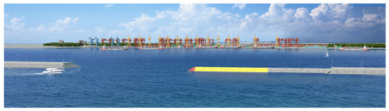
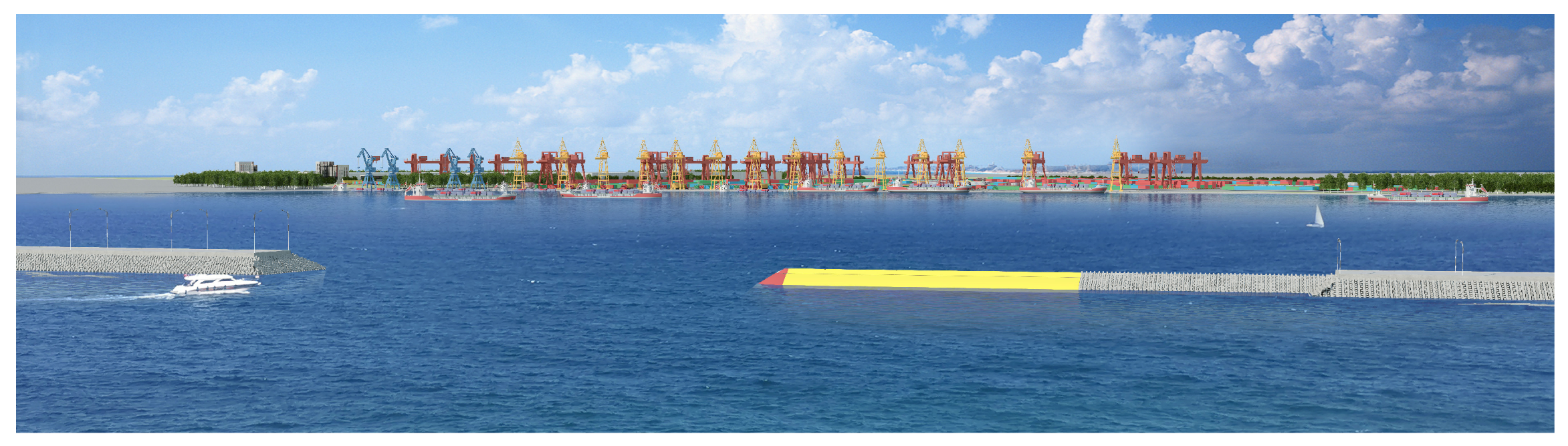
Figure 1 presents a bird’s eye view of the DULOW system incorporated at the terminal section of a shore-attached slope-ramp rubble-mound breakwater. The DULOW configuration maintains geometrical continuity with conventional breakwater slope, enabling both retrofitting of existing terminal structures and de novo construction with standardized profiles. This innovative design converts traditional passive energy dissipation through armor rocks or artificial armor units into active energy harvesting by strategically storing overtopped water volumes in reservoirs. The integrated DULOW modules achieve dual benefits: mitigating wave impact loads on breakwater while substantially reducing construction costs through infrastructure sharing, particularly in material procurement and substructure development. The modular design permits flexible scaling of unit numbers based on site-specific wave energy parameters, power generation targets, and capital investment considerations.
Figure 1.
Bird view of a DULOW device integrated into an attached breakwater.
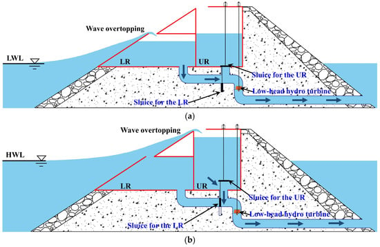
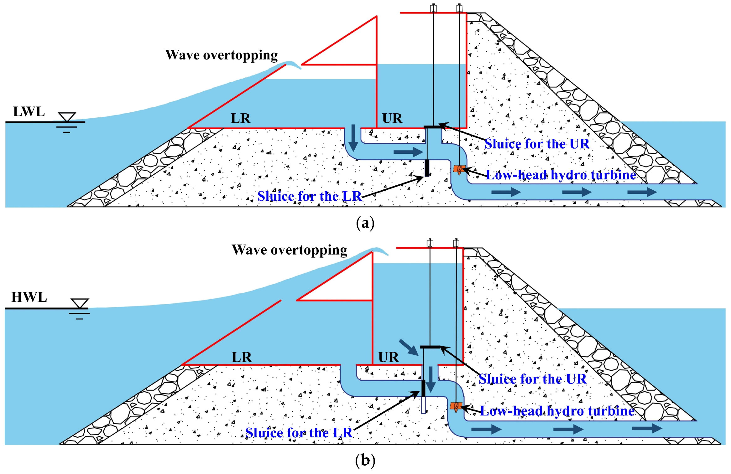
Figure 2 illustrates two-dimensional (2D) cross-sectional schematics of the DULOW integrated within a slope-ramp rubble-mound breakwater, demonstrating operation under two tidal phases. System integration requires structural modifications including optimized module width adjustments and core-stone replacements to accommodate low-head hydro turbines within reconfigured outflow channels. The vertically staggered upper reservoir (UR) and lower reservoir (LR) employ tidal phase-dependent operational strategies, utilizing identical principles to extend operational windows across tidal cycles.
Figure 2.
2D schematics of a DULOW integrated into the sloping-ramp rubble-mound breakwater. (a) LR operation; (b) UR operation mode.
During the low tidal phase, as shown in Figure 2a, wave overtopping fails to reach UR elevation, promoting UR deactivation through sluice gate closure. Concurrently, the LR maintains closed-gate storage until it reaches predetermined hydraulic head thresholds, at which point controlled water release activates the turbine-generator unit. The laboratory experimental tests in this study focus on the overtopping collection processes and discharges. At the same time, the turbine performance, electrical power output, and wave-to-wire conversion efficiency are not considered in this paper. Under high tidal conditions, as shown in Figure 2b, submerged LR operation ceases through sluice gate closure, while the UR engages in wave energy harvesting through ramp-overtopping processes. UR-initiated generation commences upon achieving critical storage levels, with released water driving a shared turbine system. This phase-oriented operational strategy allows the DULOW system to maintain overtopping wave-water collection over a wider range of tidal levels. The dual-level arrangement is mainly intended to improve tidal adaptability, rather than simply increasing the number of reservoirs for multi-stage overtopping at the same still water level. In the present DULOW concept, the lower and upper reservoirs are designed to operate alternately under different tidal levels, thereby reducing the adverse influence of tidal fluctuations on reservoir freeboard and extending the effective operating water level range.
3. Experimental Setup
All experimental tests were conducted in the wave tank at the Shandong Provincial Key Laboratory of Ocean Engineering in the Ocean University of China. The rectangular tank, with dimensions of 60.0 m in length × 36.0 m in width × 1.5 m in depth, provides controlled wave testing conditions. A piston-type wave maker mounted at the headwall section in the tank enables precise generation of regular and irregular wave scenarios with programmable wave parameters and adjustable incidence directions. A porous-media-based damping system deployed along the opposite boundary effectively attenuates wave energy through viscous dissipation. In addition, wave-absorbing materials were installed along the side walls of the 3D basin to reduce reflections from the side walls.
The physical model was designed according to the Froude similitude, with a scale ratio of 1:16. Therefore, the time and volume scale ratios per unit width were 1:4 and 1:64, respectively. Based on local environmental conditions and model design details, two tested still water levels, h = 0.25 m and h = 0.35 m, were selected to represent effective crest freeboards for the lower and upper collectors. In the model tests, the wave height of 0.04 m corresponds to a prototype-equivalent wave height of 0.64 m, and the model wave periods of 1.50~2.00 s correspond to prototype-equivalent periods of 6.00~8.00 s.
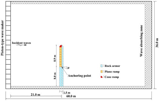
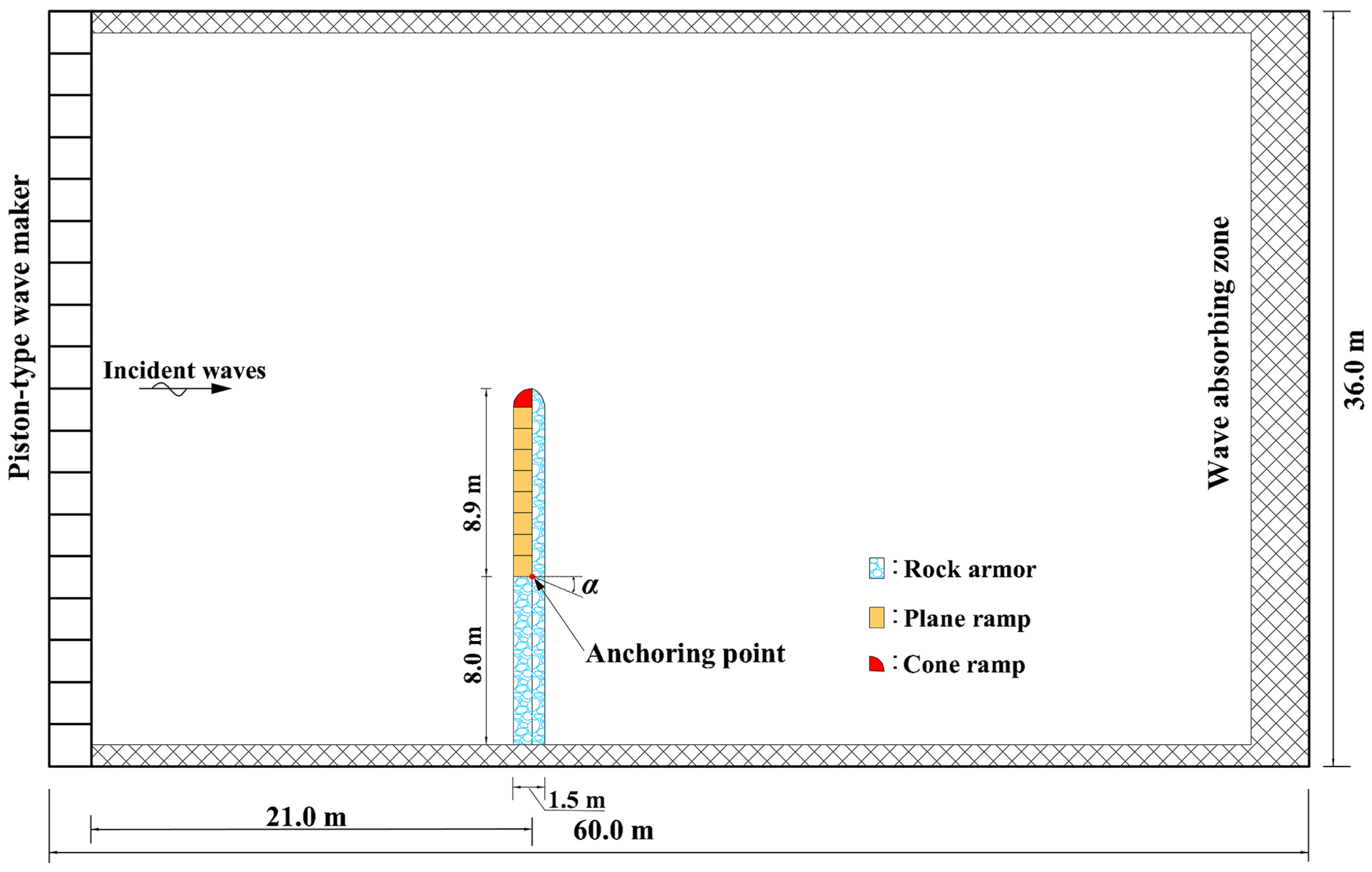
Figure 3 illustrates the model set-up in the wave tank. A model of the DULOW integrated into a slope-ramp rubble-mound breakwater was constructed in the tank attached to the side wall to simulate the connection of the full-scale structures with the shoreline. An anchoring point, deployed 21.0 m from the wave maker and 8.0 m from the side wall, served as a datum point for model positioning and construction. The model external contour measured 16.9 m in length and 1.5 m in width. The model section from the side wall to the anchoring point employed conventional breakwater armor rocks on two sides. For the lateral section, the DULOW modules with plane and cone ramps were constructed on the waveward side, and the conventional armor rocks were placed on the corresponding leeward side. The incident wave angle α, defined based on the anchoring point, is the included angle between the incident wave direction and the model longitudinal direction. During the tests, the generated waves are fixed at normal incidence, resulting in α = 0° for the initial model deployment. By rotating the entire model about the anchoring point, the effects of oblique wave incidence can be evaluated through experimental tests with various values of α.
Figure 3.
DULOW model setup in the wave tank.
In the oblique-wave tests, the shoreline-attached condition was maintained by keeping the shoreward part of the model connected to the side wall. In contrast, the whole model was rotated about the anchoring point to change the relative angle between the incident waves and the DULOW section. This experimental arrangement allowed a controlled comparison between normal and oblique wave incidences. However, side-wall reflections and diffractions near the breakwater head could not be completely eliminated due to the model’s installation in a finite-width basin and attachment to the side wall. The porous wave absorber installed along the opposite boundary was used to reduce reflected waves.
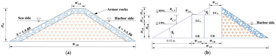
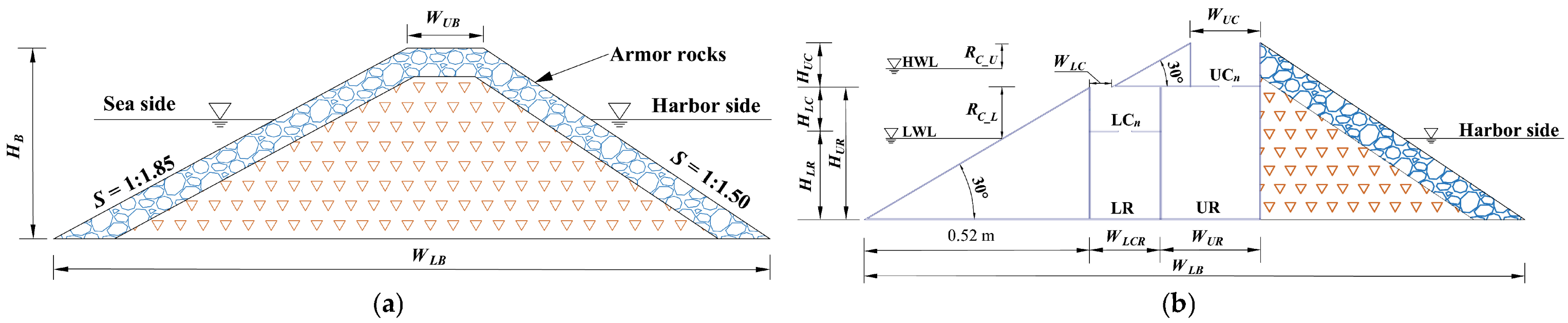
Figure 4 displays the cross-sectional profiles of the model. The conventional rubble-mound breakwater section, illustrated in Figure 4a, is trapezoidal, defined by an upper base width of WUB = 0.16 m, a lower base width of WLB = 1.50 m, and an overall height of HB = 0.40 m. The profile is constructed using core stones covered by a 0.06 m-thick layer of armor rocks. The sea-side and harbor-side slopes are 1:1.85 and 1:1.50, respectively. In accordance with the domestic breakwater design code [36], the core stone mass ranges from 2.0 g to 12.0 g. To ensure stability, the armor rock masses were amplified with a factor of 1.2 to 1.3, resulting in a mass range of 37.0 g to 49.0 g. The DULOW section, shown in Figure 4b, is a simplified model consisting solely of fundamental facilities: upper and lower ramps, collectors, and reservoirs. This section maintains the same upper and lower base widths and overall height as the breakwater section. On the harbor side, it utilizes the identical core stones, armor rocks, and profiles as the breakwater section. On the sea side, the DULOW model has a bottom width of 0.90 m. The plane ramp features a bottom width of 0.52 m with a slope angle of 30°, which is marginally larger than the slope of the sea-side slope of the conventional breakwater. The lower collectors and reservoirs have identical widths of WLCR = 0.16 m, with respective heights of HLR = 0.20 m and HLC = 0.10 m. Consequently, the lower mouth is positioned at a height of 0.30 m with a width of WLC = 0.05 m. The upper collector reservoirs have a width of WUR = 0.22 m and a height of HUR = 0.30 m. The upper ramps are staggered relative to the lower ramps but share the same slope angle of 30°. The upper collectors have the same width as the breakwater upper base and a height of HUC = 0.10 m. RC_U and RC_L denote the crest freeboards of the upper reservoir at the higher water level and the lower reservoir at the lower water level, respectively.
Figure 4.
Cross-sectional profiles of the laboratory model. (a) Breakwater section; (b) DULOW section. Blue indicate armor rock, and orange indicate core stone.
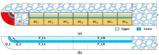
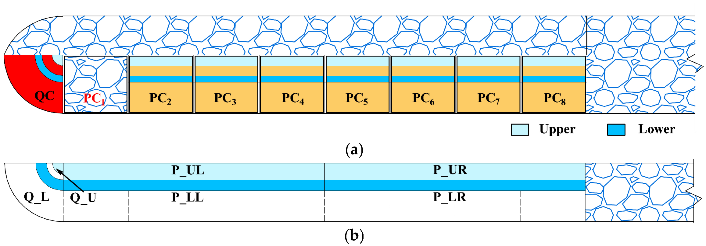
Figure 5 illustrates the modular divisions of the DULOW section, which are used to evaluate the model’s wave climbing and overtopping performance at various positions. As depicted in Figure 5a, the DULOW section is segmented into eight plane modules (PC1–PC8), each with a width of 1.0 m, and a quadrant cone module (QC) featuring a bottom radius of 0.9 m. All modules comprise ramps and individual upper and lower collectors, which are color-coded in light and lake blue, respectively. Importantly, these modules can be substituted by core stones and armor rocks, matching the cross-sectional profile of the conventional breakwater shown in Figure 4a, for example, the module PC1. When all plane and quadrant cone modules are replaced by core stones and armor rocks, the entire model effectively transforms into a conventional breakwater model. Figure 5b shows the reservoir system: the lower and upper reservoirs (Q_L and Q_U) are dedicated to QC for storing incident wave water at different water levels. Furthermore, the lower and upper reservoirs (P_LL and P_UL) serve modules PC1–PC4, collecting wave water from one to four collectors, respectively. Individual down-flowing circular exits, each with a diameter of 0.03 m, are installed on the bottom of each collector. Following an identical operating principle, reservoirs P_LR and P_UR serve modules PC5–PC8. The overtopping discharges of the DULOW model are ultimately evaluated by calculating the water volumes accumulated in these reservoirs.
Figure 5.
Modular collector and reservoir arrangements in the DULOW section. (a) Module division; (b) reservoir division.
The various configurations of module combinations are detailed in Table 1. Specifically, in Configuration S01, all DULOW modules are substituted by core stones and armor rocks, resulting in the model operating as a conventional breakwater. For the remaining four configurations, the QC is consistently utilized. The plane modules, with varying numbers of collectors and corresponding reservoirs, are employed in laboratory investigations to thoroughly evaluate the effects of these modular configurations on the operating performance of the DULOW model.
Table 1.
Modular configuration in the DULOW section.
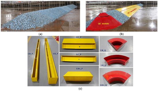
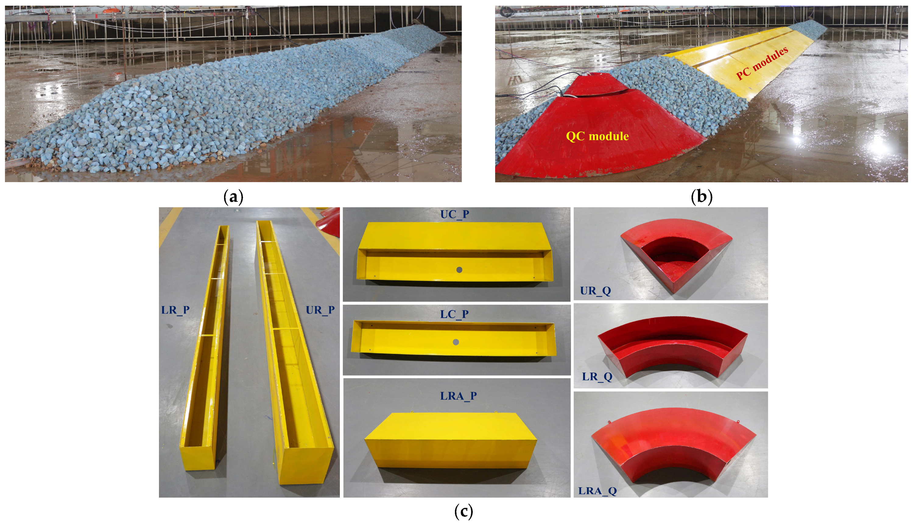
Figure 6 illustrates typical configurations of the DULOW model deployed in the wave tank with modular elements. As shown in Figure 6a, Configuration S01 serves as a conventional breakwater benchmark, with all DULOW modules removed and the section filled with core stones and armor rocks. This configuration interacts with incident waves to measure wave climbing and overtopping impacts. A typical DULOW configuration, S04 as shown in Figure 6b, utilizes a quadrant cone module and seven plane modules with PC1 replaced by a conventional breakwater section.
Figure 6.
Physical photos of the DULOW model with modular elements. (a) Configuration S01; (b) Configuration S04; (c) modular elements.
Figure 6c shows that all modular elements are prefabricated from 2.0 mm thick steel plates to resist deformations and facilitate on-site assembly. For the plane modules, the lower reservoir (LR_P) and upper reservoir (UP_P) are 4.0 m long and collectively cover four collectors to store overtopping wave water. The upper ramp and collector, each 1.0 m long, are integrated into a single unit (UC_P) for the plane modules. Conversely, the lower plane ramp (LRA_P) and lower plane collector (LC_P), both 1.0 m long, are separate components assembled using bolts. The elements for the quadrant cone module are prefabricated using an identical principle: the upper ramp, collector, and reservoir are integrated into the unit UR_Q, while the lower ramp (LRA_Q), lower collector, and reservoir (LR_Q) remain separate.
The laboratory tests utilized two water depths: a lower level of h = 0.25 m and a higher level of h = 0.35 m. The testing included two incident wave angles: α = 0° and α = 30°. Oblique waves were generated by directing forward wave incidence from the wave maker while rotating the DULOW model by 30° around its anchoring point. Both regular and irregular wave scenarios were employed. For regular wave conditions, the incident wave height was set to HS = 0.04 m, and the incident wave period TR varied across 1.50 s, 1.75 s, and 2.00 s, resulting in sixty regular-wave testing cases. For the irregular wave condition, the JONSWAP spectrum (γ = 3.3) generated the wave train. The significant wave height and period were fixed at HS = 0.04 m and TS = 1.50 s, respectively, for a total of twenty irregular-wave testing cases.
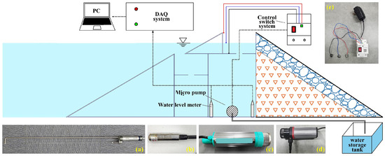
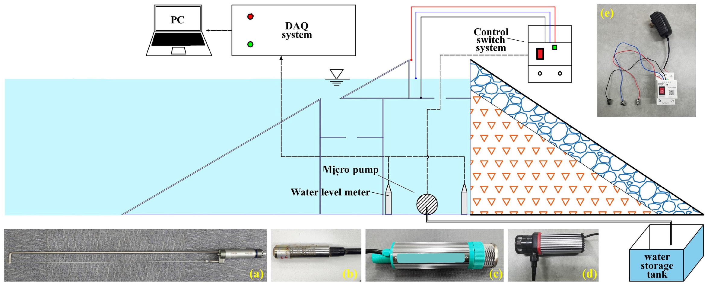
The measuring instrument chain and the data recording control system are illustrated in Figure 7. Pressure-type water-level meters are utilized to measure water level variations across the different reservoirs and to calculate instantaneous overtopping discharges. Both the wave gauges and the water level meters are connected to a 64-channel data acquisition (DAQ) system for laboratory data recording, processing, and storage. The wave gauge has a full scale (FS) of 700.0 mm and an accuracy of ± 0.5%·FS. The pressure-type water level meter has an FS of 1000.0 mm with an accuracy of ± 0.5%·FS.
Figure 7.
Instruments and control switch system. (a) Wave gauge; (b) water-level meter; (c) Kaidun-50 type micro pump; (d) WB-1003G type micro pump; and (e) water level control switch system.
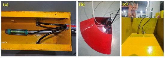
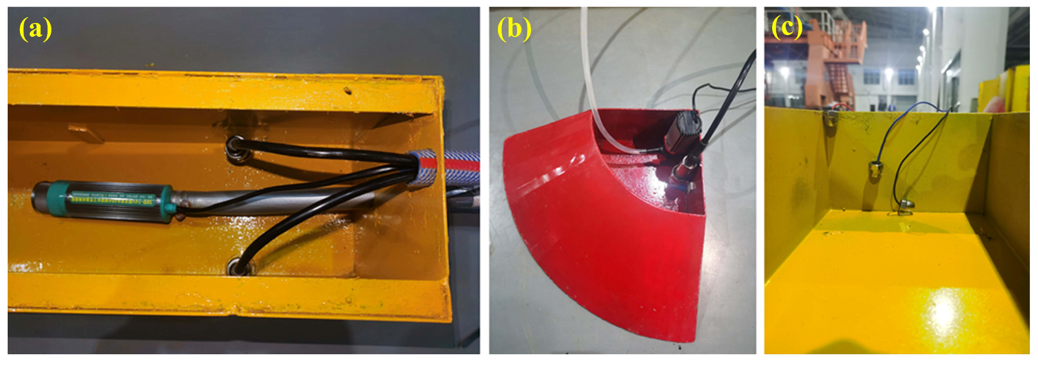
During the tests, the wave gauges were fixed at deployment points using steel supports. The water level meters were installed on the side walls, near the reservoir bottoms, to measure variations in reservoir water levels. Two meters were installed in the plane reservoirs and connected to the DAQ system through reserved openings on the side walls. One meter was installed in the quadrant cone reservoirs, connecting directly to the DAQ system through the top opening. In the plane modules, a Kaidun-50 micro pump was fixed to the bottom to drain the reservoirs, with a rated flowrate (FR) of 50.0 L/min and an error of ±3.0%·FR. In the quadrant cone module, a WB-1003G micro pump was fixed to the side wall to drain the collectors with an FR of 8.0 L/min and an error of ±2.0%·FR. An automatic control switch system was designed, installed above the model, and connected to the pump power supplies to drive the drainage process. Three contacts of the control switch system were fixed on the side walls of collectors: the grounded (black) contact was placed on the bottom, the high-level (red) contact was placed near the opening mouth, and the low-level (blue) contact was positioned at the same level as the test water depth. The installation of measuring instruments (micro pumps and control switch contacts) is displayed in Figure 8.
Figure 8.
Measuring instruments installations. (a) Water level meter in a plane reservoir; (b) water level meter and micro pump in the quadrant reservoir; and (c) contacts in a plane collector.
When a collector fills up, the high-level contact touches the free surface, closing the circuit and initializing pump operation. Conversely, when the water level decreases to the height of the low-level contact, the pump ceases draining. During regular wave tests, overtopping data for at least twenty wave cycles are recorded, starting from when the first wave successfully overtops into the reservoir. During these tests, the pump system is not activated during wave action. If the reservoir fills up in less than twenty wave cycles, the overtopping discharge is calculated using the time interval from the moment the first wave successfully overtops to the moment the reservoir is filled. After the test, the accumulated water in the reservoir is drained until the internal water level returns to the external still water level, and the overtopping volume is determined from the measured reservoir water-level variation and the reservoir geometry. For irregular wave tests, more than 1000 wave cycles are employed. Before testing, the pump discharge pipe is pre-filled to maintain continuous drainage. During wave incidence, the pump system continuously discharges overtopped water into the storage tank. The total overtopping volume is calculated from the collected water volume in the storage tank, together with the residual water volume variation remaining in the reservoirs after the test. All test cases were conducted three times, and the average values were used as the representative values for each case.
The overtopping discharge is a critical parameter for evaluating the DULOW model performance. Based on the model geometry, testing cases, and previous studies [20,21], the dimensionless overtopping discharges of the plane and quadrant cone modules are defined as follows:
where g is the gravitational acceleration and H is the incident wave height. QP_UL, QP_UR, QP_LL, and QP_LR are the dimensionless overtopping discharges of the upper and lower reservoirs on the left and right sides for the plane modules. QQ_U and QQ_L are the dimensionless overtopping discharges of the upper and lower collectors/reservoirs for the quadrant cone module. qP_UL, qP_UR, qP_LL and qP_LR are the time-averaged dimensional overtopping discharges of the upper and lower reservoirs on the left and right sides for the plane modules. For α = 30°, the characteristic collector length for the plane modules is taken as the projected length normal to the incident wave direction. qQ_U and qQ_L are the time-averaged dimensional overtopping discharges of the upper and lower collectors/reservoirs of the quadrant cone module. dm is a quarter of the circumference of the quadrant cone mouth, which is 0.13 m and 0.30 m for the upper and lower collectors, respectively.
4. Results and Discussions
4.1. Wave Motions on the Model in Regular Waves
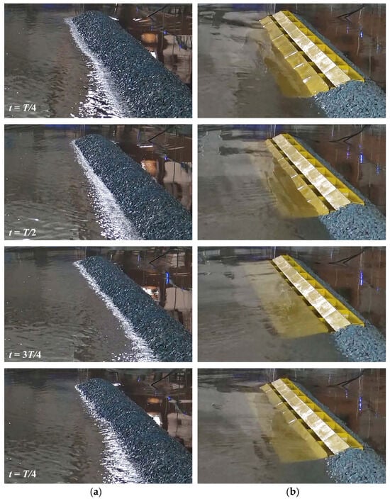
A comparative analysis of overtopping dynamics across individual wave cycles was conducted for representative configurations under regular wave conditions. This analysis aimed to elucidate the influence of the DULOW structure on wave hydrodynamics over the model. The experimental parameters were standardized at h = 0.25 m, H = 0.04 m, T = 2.00 s, and α = 0°, using Configurations S01 (a conventional rubble-mound breakwater) and S05 (DULOW model) as comparative benchmarks.
Figure 9 chronologically details wave–structure interactions for forward-propagating regular waves (h = 0.25 m, H = 0.04 m, T = 2.00 s, and α = 0°). The temporal sequencing was initialized at the first wave-model contact, with sampling intervals set at quarter- wave-cycle increments. Wave propagation proceeds from left to right in the tank visualization. During the initial two-quarter cycles, comparable wave run-up patterns emerged for both configurations due to orthogonal wave incidence, as evidenced by identical maximum run-up elevations across monitoring positions. Divergence became pronounced in the third-quarter cycle when Configuration S05 achieved reservoir overtopping and wave-breaking phenomena during ascent, contrasting sharply with the non-overtopping behavior of Configuration S01. The fourth-quarter cycle revealed amplified wave amplitudes for configuration S05, with structural differences between the conventional breakwater and the DULOW system being most discernible at the transitional interface section.
Figure 9.
Wave motions on the model under a forward incident regular wave condition (α = 0°). (a) S01; (b) S05.
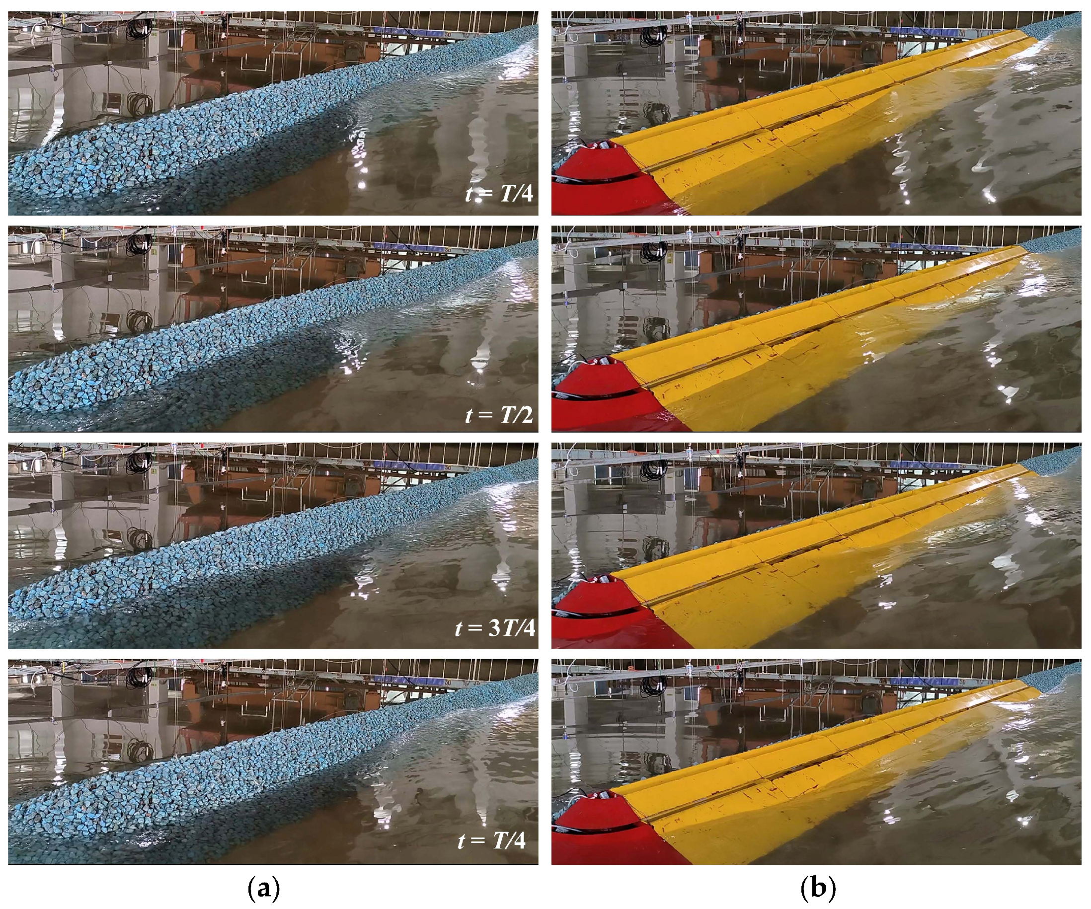
Figure 10 illustrates wave kinematics acting upon the model under oblique wave conditions (h = 0.25 m, H = 0.04 m, T = 2.00 s, and α = 30°). Chronographic documentation commencing at the initial wave-model contact was sampled at quarter-cycle intervals. During the period from 0 to t = T/4, shore-parallel wave advancement along the structure showed reduced run-up for S01, attributable to its hydraulic roughness characteristics, with limited overtopping reaching collector PC4. By t = T/2, progressive fluid migration achieved sustained overtopping into PC2 and PC3, concurrent with the initiation of a secondary wave front at the seaward slope. Notably, Configuration S01 exhibited premature fluid recession at this phase due to inertial mass restriction and armor-layer energy dissipation. At t = 3T/4, the primary wave flux became confined to PC1 absorption, while the secondary front propagated shoreward to PC7 and PC8, resulting in a complete loss of terminal breakwater overtopping capacity. The culmination of the full cycle demonstrates secondary wave penetration to PC6 alongside total fluid evacuation from the structural surface, establishing a clear temporal differentiation in energy dissipation pathways between the conventional breakwater and DULOW system.
Figure 10.
Wave motions on the model under an oblique incident regular wave condition (α = 30°). (a) S01; (b) S05.
4.2. Overtopping Performance Evaluation of the DULOW System
4.2.1. Water Level Variations in the Reservoirs
The overtopping behaviors of the DULOW system are characterized by instantaneous water level variations in the reservoirs, quantified through the dimensionless parameter WR, where WR = wR/RC. Here, wR denotes the dimensional instantaneous water level variation, and RC represents the reservoir crest freeboard under corresponding environmental conditions. The original dimensional instantaneous water level variations in the reservoirs under typical test conditions (h = 0.25 m, H = 0.04 m, T = 2.00 s, and α = 0°) are presented in Figure 11. Both reservoirs exhibit pronounced raw data fluctuations due to free-surface oscillations from wave intrusion. While measurable, these water-level changes prove inadequate for precise inflection point identification, which is required to determine the overtopping duration between initial wave entry and reservoir filling.
Figure 11.
Original raw data of instantaneous water level variations in the reservoirs. (a) Reservoirs integrated with plane collectors; (b) reservoirs integrated with quadrant cone collectors.
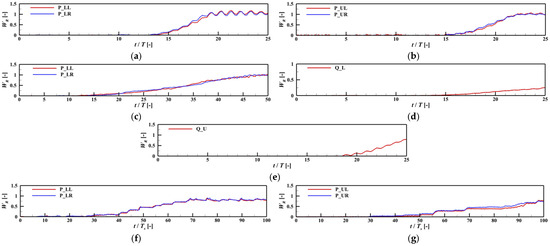
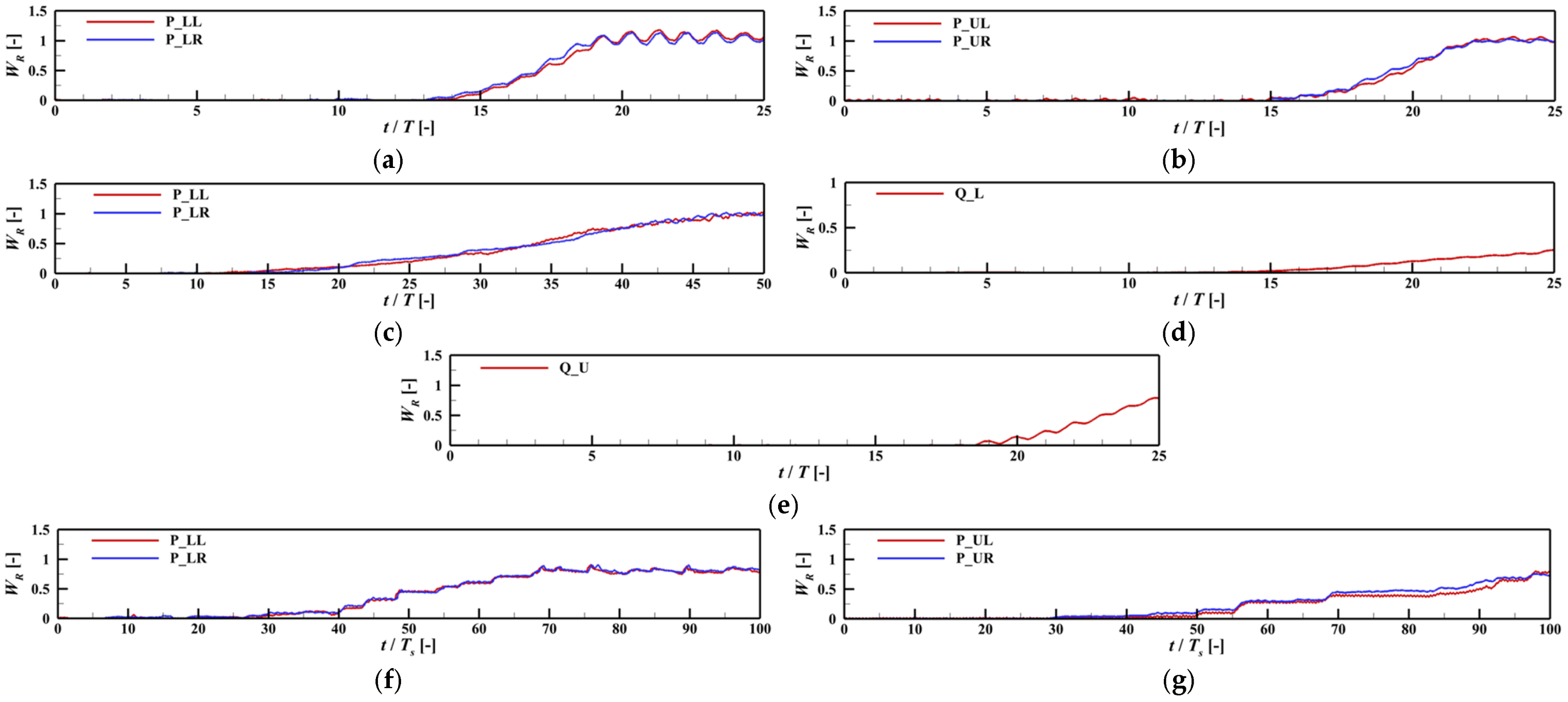
Figure 12 demonstrates moving-average filtered instantaneous water level variations in the reservoirs across test conditions. At h = 0.25 m, as shown in Figure 12a, plane reservoirs achieve synchronized filling within seven wave cycles, with fluctuation periods matching the incident waves, thereby enabling average overtopping discharge calculation through duration based averaging. At h = 0.35 m, as shown in Figure 12b, delayed filling of the upper plane reservoir occurs due to energy dissipation caused by the presence of lower reservoir openings, which reduces wave propagation to the upper chambers. For α = 30°, as shown in Figure 12c, oblique wave incidence extends the filling duration to 30 cycles, resulting in attenuated fluctuations. This results from extended wave trajectories along the sloped ramp and sequential wave entry into the collectors, creating a 0.4-cycle phase difference between reservoirs. Notably, upper plane reservoirs remain unfilled at h = 0.35 m due to the increased travel distance and interference of the lower reservoir.
Figure 12.
Filtered instantaneous water level variation in the reservoirs. (a) lower plane reservoirs for h = 0.25 m, α = 0°; (b) upper plane reservoirs for h = 0.35 m, α = 0°; (c) lower plane reservoirs for h = 0.25 m, α = 30°; (d) lower quadrant cone reservoirs for h = 0.25 m, α = 0°; (e) Upper quadrant cone reservoirs for h = 0.35 m, α = 0°; (f) lower plane reservoirs for h = 0.25 m, HS = 0.04 m, TS = 2.00 s, α = 0°; and (g) upper plane reservoirs for h = 0.35 m, HS = 0.04 m, TS = 2.00 s, α = 0°.
Figure 12d,e presents the water-level variations in quadrant cone reservoirs at different environmental water levels. At h = 0.25 m, as shown in Figure 12d, the incident waves encounter difficulty climbing the conical ramp, slowing lower reservoir filling compared to plane counterparts. The upper quadrant cone reservoir in Figure 12e exhibits accelerated level rise but slower wave storage due to reduced capacity. For the irregular wave scenario at h = 0.25 m, as shown in Figure 12f, reservoir filling initiates at the 27th wave, triggering micro-pump activation upon reaching high-level contact. Subsequent operation maintains dynamic equilibrium between wave inflow and pump drainage by activating the low-level contact. At h = 0.35 m, as shown in Figure 12g, upper reservoirs remain unfilled, preventing pump initialization.
4.2.2. Overtopping Discharges of the DULOW System
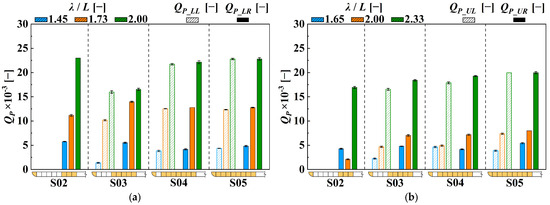
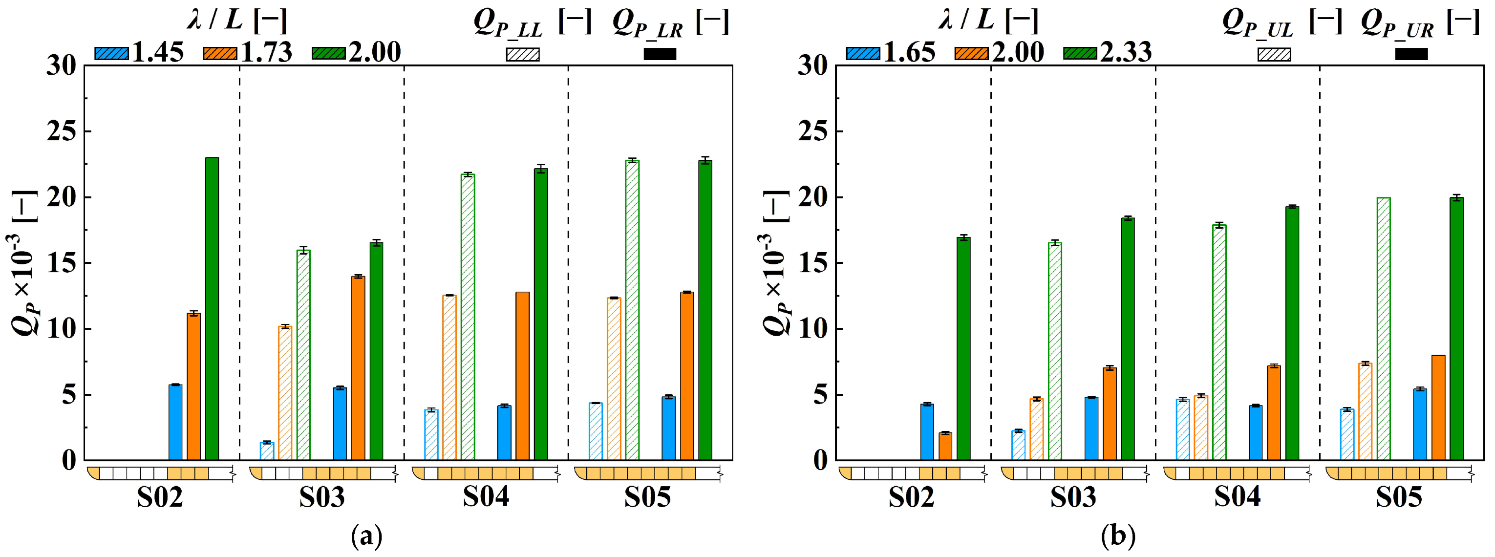
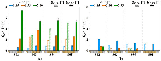
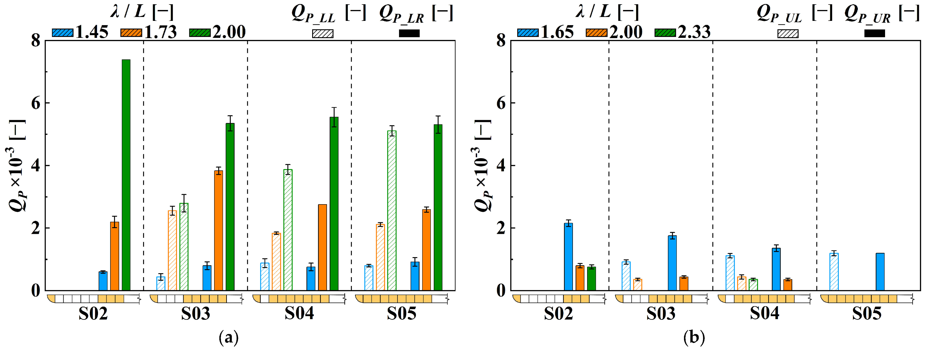
Overtopping discharge is a critical indicator for demonstrating the operating performance of an overtopping WEC. The nondimensional time-averaged overtopping discharges of plane reservoirs for various configurations in regular waves with an incidence angle of α = 0° are compared as bar charts in Figure 13, with error bars indicating the standard deviation (SD) of the repeated tests. In general, for any specific module configuration, the nondimensional time-average overtopping discharge reaches its maximum when the relative incident wave length λ/L is the largest, because incident waves with longer periods carry more power and can climb the slope ramp, resulting in higher overtopping discharges.
Figure 13.
Nondimensional time-averaged overtopping discharges of the plane reservoirs for four configurations (H = 0.04 m and α = 0°). (a) h = 0.25 m; (b) h = 0.35 m.
For h = 0.25 m, as shown in Figure 13a, only the reservoir at the lower still water level can absorb incident wave water, and most values of QP_LR are larger than QP_LL for different module configurations. As more modules are replaced by armor rocks from right to left, the values of QP_LL gradually reduce and become zero for S02 due to the increased presence of armor rocks. Compared to Configuration S05, the average overtopping discharge under three incident wave lengths for Configuration S03 is reduced by 30.3%. On the other hand, the values of QP_LR exhibit minor differences across different module configurations. The plane reservoir is responsible for storing the incident wave water from the plane collector on the right side, which is trapped by the side wall and armor rocks on both sides, making it easier for the water to climb higher and enter the reservoir, even causing larger values of QP_LR for S02.
For h = 0.35 m, as shown in Figure 13b, the lower-level reservoirs are submerged, and only the higher-level reservoirs can store incident wave water. The testing results show that the variation patterns of overtopping discharges of the higher reservoirs across different configurations are similar to those at the lower level. Meanwhile, for any specific configuration at a higher still water level, the overtopping discharges are smaller than those at a lower level because more wave power is dissipated along the longer climbing route to the higher-level reservoirs. For Configuration S05 as an example, as the water depth increases from 0.25 m to 0.35 m, the average values of QP_LL and QP_LR under three incident wave length conditions are smaller than those for QP_LL and QP_LR by 26.6% and 21.1%, respectively.
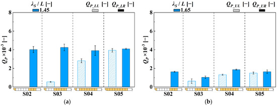
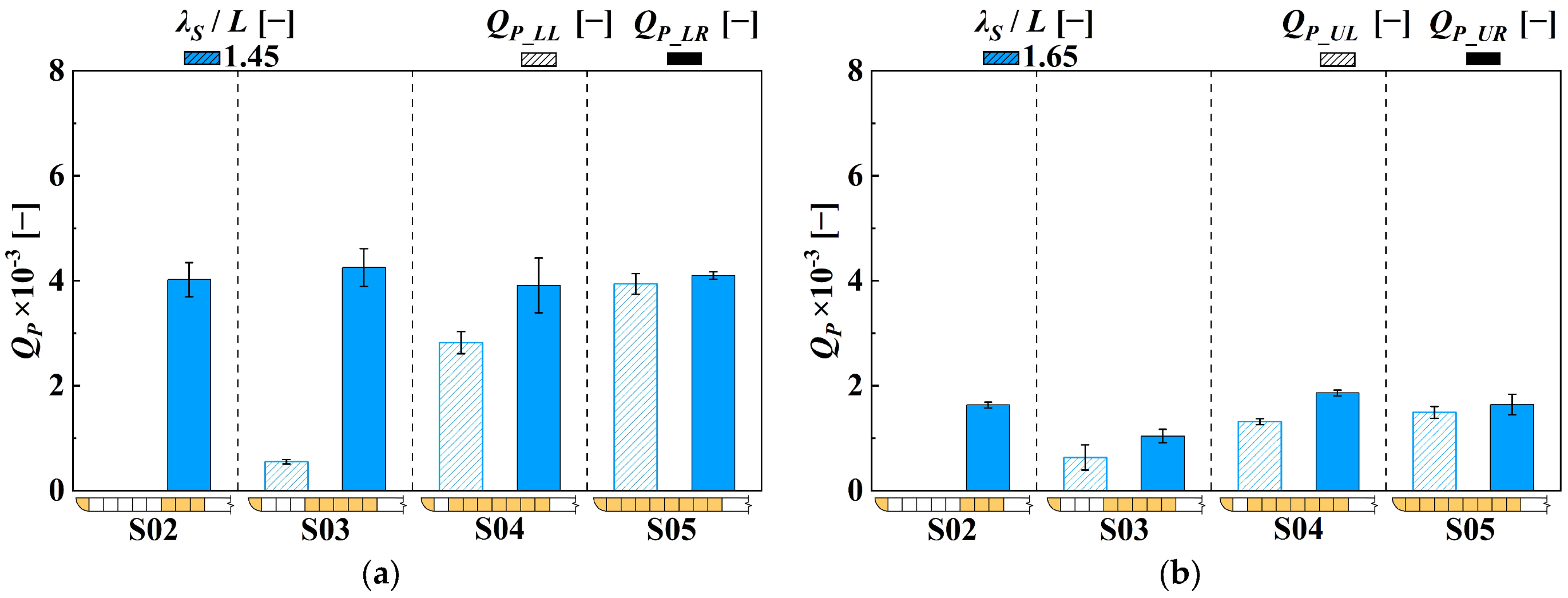
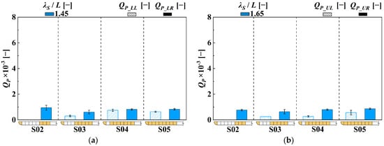
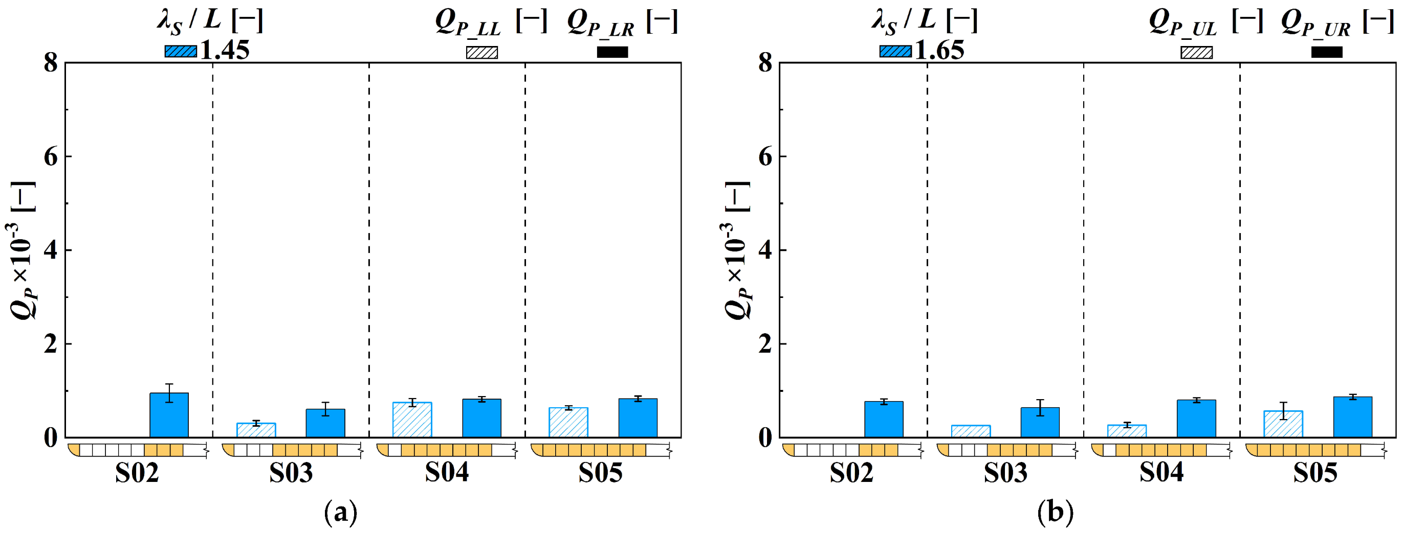
Similar to Figure 13, Figure 14 presents nondimensional time-averaged overtopping discharges of plane reservoirs for various configurations in regular waves under an incidence angle of α = 30°. For h = 0.25 m, as shown in Figure 14a, the overtopping discharges in oblique waves are significantly smaller than those in head-on waves. By comparing the values of QP_LL and QP_LR, it can be found that the overtopping discharges for the plane lower reservoir on the left side decrease as the configuration changes from S05 to S02, while the overtopping discharges for the plane lower reservoir on the right side exhibit minor differences. These phenomena can be explained as follows: the waves arrive at the plane lower reservoir on the right side, which is less affected by the armor rocks, resulting in minor differences in overtopping discharges across different configurations. On the other hand, the plane lower reservoir on the left side is located at the far end of the model, where a longer climbing route causes the incident waves to be more affected by armor rocks. This is influenced by the decreasing number of overtopping modules, leading to a reduction in overtopping wave water collection in the reservoirs. For h = 0.35 m, as shown in Figure 14b, under the influence of the open mouth of the lower reservoirs, the values of QP_UL and QP_UR all decrease, with some reducing to zero.
Figure 14.
Nondimensional time-averaged overtopping discharges of the plane reservoirs for four configurations (H = 0.04 m and α = 30°). (a) h = 0.25 m; (b) h = 0.35 m.
Based on the standard deviation data of the experimental cases, the coefficient of variation (COV) was used to evaluate the repeatability of the measurements. Under head-on regular-wave conditions, most effective overtopping cases exhibited COV values below 5%, with only a few low-discharge cases reaching approximately 8%. Under oblique regular-wave conditions, the COV values were generally below 10%, while some low-discharge cases showed larger values of up to approximately 15%. The increased variability under oblique incidence is mainly attributed to non-uniform overtopping along the collectors.
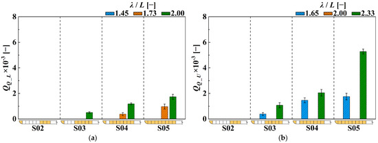
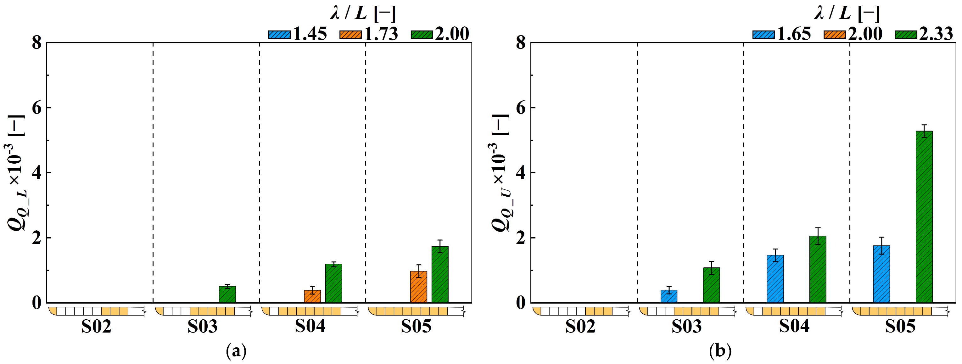
Figure 15 presents nondimensional time-averaged overtopping discharges of the quadrant cone reservoir for various configurations in regular waves under an incidence angle of α = 0°. The quadrant cone reservoir stores significantly less overtopping wave water than the plane ones because the quadrant cone reservoir is located at the breakwater head, where the incident waves diffract and bypass the breakwater head with accessory structures to propagate to the leeward field. Only a small amount of water climbs to the collector, resulting in a significant reduction in overtopping discharges. In addition, only the quadrant cone reservoir for Configuration S02 cannot receive incident wave water. For h = 0.25 m, as shown in Figure 15a, the nondimensional overtopping discharge for any specific relative wave length gradually reduces as the configuration changes from S05 to S02, becomes zero for S03 at λ/L = 1.73 and for S02 at λ/L = 2.00. No overtopping discharges are recorded for all configurations at λ/L = 1.45. For h = 0.35 m, as shown in Figure 15b, the QQ_U value shows a decreasing trend with a decrease in module number from Configuration S05 to S03 for λ/L = 1.65 and λ/L = 2.33, which is caused by interference cancellations between incident and reflected waves in front of the quadrant cone collector, resulting in wave height reduction that hinders the incident waves from entering the collector.
Figure 15.
Nondimensional time-averaged overtopping discharges of the quadrant reservoirs for four configurations (H = 0.04 m and α = 0°). (a) h = 0.25 m; (b) h = 0.35 m.
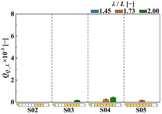
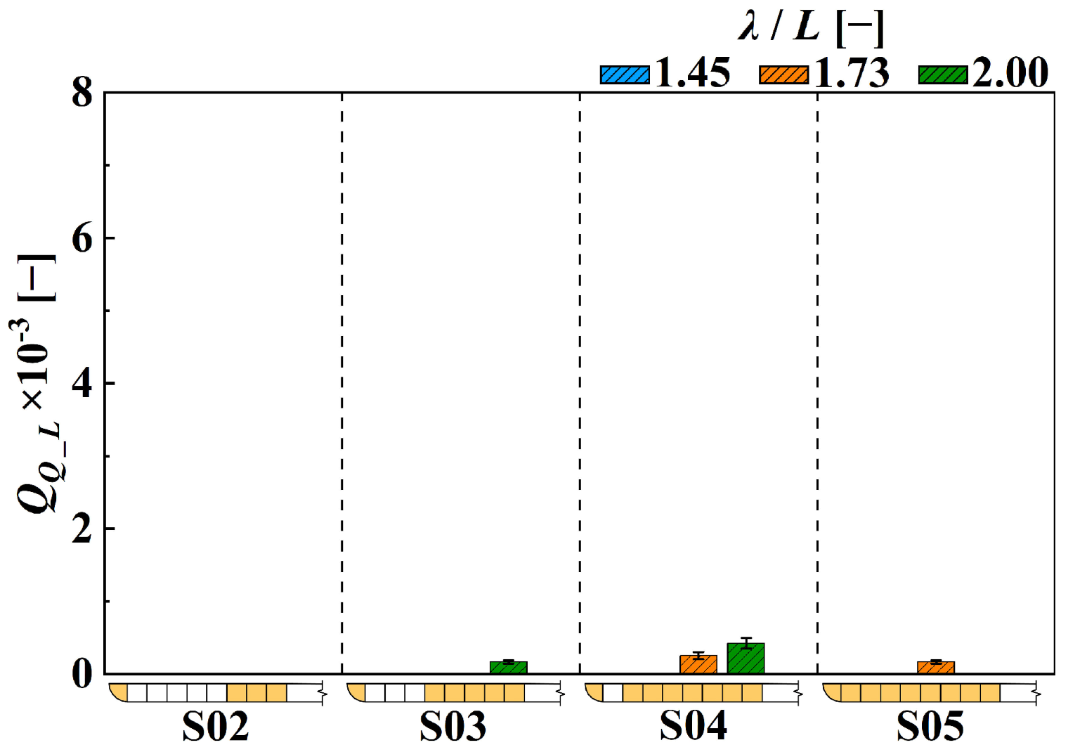
For α = 30°, the quadrant cone collector and reservoir at the still higher water level cannot receive any incident wave water. Therefore, only the nondimensional time-averaged overtopping discharges for different configurations in regular waves at the lower water level (h = 0.25 m) are compared in Figure 16. The overtopping discharges for S03 with λ/L = 2.00, S04 with λ/L = 1.73 and λ/L = 2.00, and S05 with λ/L = 1.73 can be observed with extremely small values.
Figure 16.
Nondimensional time-averaged overtopping discharges of the quadrant reservoirs for four configurations (H = 0.04 m and α = 30°).
The nondimensional overtopping discharges collected by the plane collectors and reservoirs for different configurations in irregular waves at incidence angles of α = 0° and α = 30° are presented in Figure 17 and Figure 18, respectively. For α = 0°, as shown in Figure 17, the values of QP_LL and QP_UL decrease gradually as the number of overtopping modules decreases, exhibiting identical variation patterns to those in regular waves. For α = 30°, as shown in Figure 18, the variation pattern of overtopping discharges against module configurations in irregular waves is similar to that in regular waves. The values of QP_LR and QP_UR exhibit minor differences, while the values of QP_LL and QP_UL decrease gradually as the number of armor rock modules increases on the slope surface. In general, the overtopping discharges in irregular waves for any specific configuration are lower than those in regular waves. Although some large waves can enhance the transient discharge in a short period, a considerable proportion of smaller waves fail to reach the collectors, thereby reducing the time-averaged overtopping discharge.
Figure 17.
Nondimensional time-averaged overtopping discharges of the plane reservoirs for four configurations (HS = 0.04 m, TS = 1.50 s, and α = 0°). (a) h = 0.25 m; (b) h = 0.35 m.
Figure 18.
Nondimensional time-averaged overtopping discharges of the plane reservoirs for four configurations (HS = 0.04 m, TS = 1.50 s, and α = 30°). (a) h = 0.25 m; (b) h = 0.35 m.
Under head-on irregular-wave conditions, the COV values are generally below 20%, with an average of approximately 9.5%. Under oblique irregular-wave conditions, the scatter was higher, with most effective cases showing COV values of approximately 6–25% and an average value of approximately 19.1%. The larger scatter is mainly attributed to the intermittent nature of irregular-wave overtopping and non-uniform wave entry into the collectors.
4.2.3. Semi-Empirical Formula for Overtopping Discharge Prediction of the DULOW System
A semi-empirical formula is proposed to describe the overtopping discharge of the DULOW system within the tested range. The formula is based on the present experimental results and a general form of overtopping discharge expressions used in previous studies [37]. Because the quadrant cone collectors collected limited overtopped water and no overtopping was observed in several cases, they were excluded from the formula development. Accordingly, the proposed formula only focuses on describing the overtopping discharge of the plane collectors and reservoirs in the tested DULOW configuration. The overtopping discharge prediction formula can be expressed as follows:
where q is the overtopping discharge of the DULOW system; τ is the 3D attenuation effect coefficient; θ is the slope angle of the ramp; ξ is the wave breaking coefficient (Iribarren number), which accounts for the combined influence of wave steepness and ramp slope, and is defined as follows:
where λ is the incident wavelength. In addition, the effective freeboard φR can be expressed as follows:
where Rc is the crest freeboard of the reservoir, representing RC_U and RC_L at different still water levels; γw represents the influences of the lower collectors on the overtopping behaviors; γε represents the roughness and permeability of the slope surface on the overtopping behaviors; γα represents the effects of incident wave directions, and based on the laboratory test results in this study, which can be expressed as follows:
The coefficients in the formula were determined from the present experimental results with reference to the observed overtopping process. The coefficient τ represents the overall three-dimensional attenuation associated with wave diffraction, reflection, and waterflow spreading around the pier-type breakwater head and was set at 0.4 for the tested layout. The coefficient γw accounts for the influence of the lower collectors on the overtopping process at the upper level. Based on the measured reduction in the upper-level overtopping discharge, γw was set at 1.0 at the lower still-water level and 0.76 at the higher still-water level. The coefficient γε reflects the combined influence of slope-surface roughness, permeability, and collector arrangement, and was set to 0.60, 0.70, 0.80, and 0.85 for configurations S02–S05, respectively. The coefficient γα accounts for the effect of oblique wave incidence. These coefficients should be regarded as empirical parameters for the present DULOW configuration and require further validation before being applied to other layouts or hydraulic conditions.
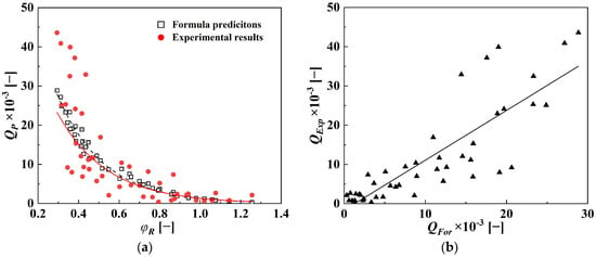
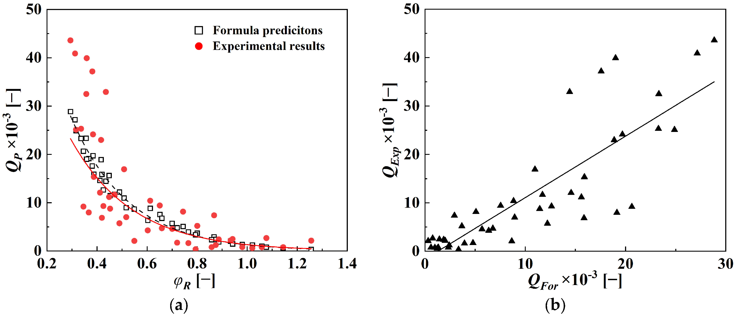
The calculated results obtained from the semi-empirical formula are compared with the experimental results in Figure 19. As shown in Figure 19a, the dimensionless overtopping discharge Qp plotted against the effective freeboard φR for both formula predictions and experimental results exhibits a rapid decreasing trend followed by mild converging trends. Both the formula and experimental data fit the exponential distribution characteristics. In addition, the determination coefficients of formula predictions and experimental results are 0.98 and 0.68 [38], respectively, indicating that the formula predictions agree well with the exponential curves, while the experimental results exhibit a large degree of scattering. A further analysis of the correlation between formula predictions and experimental results is shown in Figure 19b. The results show that the correlation coefficient between formula predictions and experimental results is 0.84, indicating that the varying patterns of the two data series show good positive correlations. On the other hand, their root-mean-square deviation is 7.1 × 10⁻³, indicating that the prediction amplitudes of the overtopping discharge still have relatively significant deviations. The scatter in the data points is caused by both experimental variability and limitations of the semi-empirical formulation. The repeatability of the overtopping measurements was evaluated through repeated tests, and the COV values were within acceptable ranges. These deviations might be caused by the limitations in the number of laboratory testing cases and restrictions in the semi-empirical formula predictions. Certainly, it is necessary to conduct laboratory tests with more incident wave heights, periods, still water depths, incident wave angles, and slopes to refine the prediction formula and enhance the correlation coefficient between experimental results and formula predictions.
Figure 19.
Comparisons of formula predictions and experimental results of overtopping discharges. (a) Overtopping discharges against φR; (b) formula predictions versus experimental results.
4.3. Engineering Implications and Limitations
Compared with existing overtopping devices, such as the OBREC [21], SSG [17], and DFOC [29] concepts, the proposed DULOW system is designed for tide-varying pier-type breakwater applications. OBREC-type devices have been more extensively studied as breakwater-integrated OWECs, focusing on hydraulic and structural performance. In contrast, the present study primarily focuses on overtopping discharge and reservoir filling behavior. SSG-type devices use multiple-level reservoirs to amplify wave-water capture at a single still- water level. In contrast, the dual-level arrangement of DULOW is primarily designed to enhance tidal adaptability by allowing the lower and upper reservoirs to operate at different water levels. Compared to DFOC-type concepts, the DULOW model has not yet been examined for adjustable geometry, long-term coastal protection effects, and turbine-coupled performance. The present results should be regarded as a preliminary evaluation of the overtopping performance of a fixed-geometry DULOW model.
Experimental results also guide the layout of collector modules. The plane collectors showed substantially higher overtopping discharge than quadrant cone collectors, indicating that straight ramp-type collectors are more effective for wave-water collection in the tested layout. The quadrant cone module collects limited overtopped water under the tested conditions in this study and is recommended not as a primary option. Its conical geometry is similar to that of conventional rubble-mound breakwater head structures, which can be settled at the breakwater head as a protective system, replacing part of the armor layer. Under other incident wave directions, especially when waves first interact with the quadrant cone module, its wave-collecting function may become more significant. In addition, the reduced discharge of the upper collectors at the higher still water level and lower discharges under oblique wave incidence indicate that collector elevation and dominant wave direction should be considered in practical layout design.
The present study focuses on reservoir filling behavior and overtopping discharge. Other aspects, such as turbine performance, electrical output, annual energy production, long-term structural loading, reflection performance, and prototype-scale operation, were not investigated. While wave-dissipating nets and a porous damping system were used in the wave tank to reduce reflected wave energy, the reflection coefficient in front of the DULOW model was not systematically measured. Consequently, future tests should include incident–reflected wave separation to quantify the reflection characteristics of the integrated breakwater–DULOW system.
5. Conclusions
A dual-level overtopping wave energy converter integrated with a pier-type slope-ramp breakwater is proposed to satisfy oceanic environmental conditions in the Chinese coastal area. The DULOW device employs dual-level reservoirs to accommodate operational conditions at different tidal levels, thereby extending the overall operation period. An experimental laboratory investigation was conducted on the overtopping performance under various wave conditions. This study focuses on reservoir filling behavior and overtopping discharge, while turbine performance, electrical output, and wave-to-wire conversion efficiency are outside its scope. Five module configurations were examined to assess the overtopping wave-water collecting capabilities in both regular and irregular wave scenarios. A semi-empirical formula was proposed to describe the overtopping discharge variation in the tested DULOW configuration under the examined conditions.
For the overtopping performance, as the number of plane collectors decreases, the dimensionless overtopping discharges of plane collectors near the breakwater end exhibit minor differences, while the overtopping discharges decrease gradually at and near the breakwater head. As the configuration changes from S05 to S03, the overtopping discharge near the breakwater head is reduced by 30.3%. At the higher still water level, due to the presence of lower collectors, the dissipation of incident waves is enhanced, and the overtopping discharges are smaller than those at the lower still water level. For configuration S05, the overtopping discharges of lower collectors and reservoirs near the breakwater end and head are larger than those of higher collectors and reservoirs by 78.2% and 79.7%, respectively. In addition, the overtopping discharges of the quadrant cone collector are significantly smaller than those of plane collectors, and the overtopping phenomenon is not even observed in some cases. Under irregular conditions, the variation pattern of overtopping discharges against the number of plane collectors is similar to that under regular wave conditions. In contrast, a greater number of small waves fail to enter the reservoir, resulting in overtopping discharges that are smaller than those under regular wave conditions.
Based on the experimental results, a semi-empirical formula considering 3D effects, slope-ramp angle and roughness, the presence of lower collectors, and incident wave direction is proposed to predict the overtopping discharges of the DULOW device equipped only with plane collectors and reservoirs. The formula describes the general variation trend of overtopping discharge with effective crest freeboard within the tested range. However, because the coefficients were determined from the present experimental dataset and only one wave height was tested, the formula should be regarded as a preliminary empirical expression for the tested DULOW configuration. Additional experimental data are required to further refine the formula parameters and improve its applicability.
Author Contributions
Conceptualization, Z.L.; methodology, Z.L. and G.Z.; investigation, G.Z., L.D., Z.H. and H.N.; data curation, G.Z.; writing—original draft preparation, Z.L. and G.Z.; writing—review and editing, Z.L. and G.Z.; visualization, Z.L. and G.Z.; funding acquisition, Z.L. All authors have read and agreed to the published version of the manuscript.
Funding
This research was funded by the National Key R&D Program of China (Grant No.: 2023YFB4204100), the National Natural Science Foundation of China (Grant No.: 52471308), the Shandong Provincial Major Basic Research Project of Natural Science Foundation (Grant No.: ZR2021ZD23), the Young top-notch talent project of National Ten Thousand Talent Program, and the Program of Introducing Talents of Discipline to Universities (“111” project, Grant No. B14028).
Data Availability Statement
The original contributions presented in this study are included in the article. Further inquiries can be directed to the corresponding author(s).
Conflicts of Interest
Author Zhen Liu was employed by Rizhao Port Group. The remaining authors declare that the research was conducted in the absence of any commercial or financial relationships that could be construed as a potential conflict of interest.
Abbreviations
The following abbreviations are used in this manuscript:
| DULOW | Dual-Level Overtopping Wave energy converter |
| WEC | Wave Energy Converter |
| OWECs | Overtopping Wave Energy Converter |
| OBREC | Overtopping Breakwater for Energy Conversion |
| SSG | Sea Slot-cone Generator |
| COV | coefficient of variation |
| DFOC | Dual Function Overtopping Converter |
References
- Liao, C.; Tong, D.; Chen, L. Pore pressure distribution and momentary liquefaction in vicinity of impermeable slope-type breakwater head. Appl. Ocean Res. 2018, 78, 290–306. [Google Scholar] [CrossRef] [Scilit]
- Carro, H.; Sande, J.; Figuero, A.; Alvarellos, A.; Peña, E.; Rabuñal, J.; Guerra, A.; Pérez, J.D. Machine learning tool for wave overtopping prediction based on the safety-operability ratio. Ocean Eng. 2024, 312, 119006. [Google Scholar] [CrossRef] [Scilit]
- Su, S.F.; Chen, I.A.; Wang, P.W. Comparative Study of Wave-Resolving Models for Typhoon-Induced Harbor Oscillations. J. Mar. Sci. Eng. 2025, 13, 2305. [Google Scholar] [CrossRef] [Scilit]
- Koosheh, A.; Etemad-Shahidi, A.; Cartwright, N.; Tomlinson, R.; van Gent, M.R.A. Wave overtopping layer thickness on the crest of rubble mound seawalls. Coast. Eng. 2024, 188, 104441. [Google Scholar] [CrossRef] [Scilit]
- Jebbad, R.; Sierra, J.P.; Gironella, X.; Mösso, C.; González-Marco, D.; Lionello, P. Uncertainty in the Assessment of Wave Overtopping in Mediterranean Moroccan Ports Associated with Climate Change. J. Mar. Sci. Eng. 2025, 13, 2021. [Google Scholar] [CrossRef] [Scilit]
- Vicinanza, D.; Lauro, E.D.; Contestabile, P.; Gisonni, C.; Lara, J.L.; Losada, I.J. Review of innovative harbor breakwaters for wave-energy conversion. J. Waterw. Port Coast. Ocean Eng. 2019, 145, 03119001. [Google Scholar] [CrossRef] [Scilit]
- Calheiros-Cabral, T.; Rosa-Santos, P.; Taveira-Pinto, F.; Lara, J.L. Harnessing wave energy through breakwater integration: A review of technologies, deployment strategies and an open-access database. Renew. Sustain. Energy Rev. 2025, 223, 115975. [Google Scholar] [CrossRef] [Scilit]
- Setayesh, P.; Moghim, M.N. An analytical-experimental study of wave overtopping in the OBREC device utilizing the maximum wave momentum flux approach. Ocean Eng. 2025, 337, 121879. [Google Scholar] [CrossRef] [Scilit]
- Boodoo, A.; Cross, J.S.; Ridgewell, C.; Kortelainen, V.; Vuorinen, M.; Harouna-Mayer, A. A Techno-Economic framework for Dual-Purpose wave Farms: Integrating coastal protection benefits into the Levelized cost of energy assessment. Energy Convers. Manag. 2026, 349, 120887. [Google Scholar] [CrossRef] [Scilit]
- Astariz, S.; Iglesias, G. Wave energy vs. other energy sources: A reassessment of the economics. Int. J. Green Energy 2016, 13, 747–755. [Google Scholar] [CrossRef] [Scilit]
- Boodoo, A.; Cross, J.S.; Ridgewell, C.; Kortelainen, V.; Vuorinen, M.; Harouna-Mayer, A. Long-term impacts and design considerations of dual-purpose wave farms for energy generation and coastal protection. Appl. Energy 2025, 401, 126805. [Google Scholar] [CrossRef] [Scilit]
- Cao, D.; He, J.; Chen, H. Empirical predictions on wave overtopping for overtopping wave energy converters: A systematic review. Processes 2024, 12, 1940. [Google Scholar] [CrossRef] [Scilit]
- Palma, G.; Contestabile, P.; Zanuttigh, B.; Formentin, F.M.; Vicinanza, D. Integrated assessment of the hydraulic and structural performance of the OBREC device in the Gulf of Naples, Italy. Appl. Ocean Res. 2020, 101, 102217. [Google Scholar] [CrossRef] [Scilit]
- Cascajo, R.; García, E.; Quiles, E.; Correcher, A.; Morant, F. Integration of marine wave energy converters into seaports: A case study in the port of Valencia. Energies 2019, 12, 787. [Google Scholar] [CrossRef] [Scilit]
- Kofoed, J.P. Wave Overtopping of Marine Structures—Utilization of Wave Energy. Ph.D. Dissertation, Aalborg University, Aalborg, Denmark, 2002. [Google Scholar]
- Meer, J.W.V.D.; Janssen, J.P.F.M. Wave run-up and wave overtopping at dikes. Am. Soc. Civ. Eng. 1995. Available online: https://www.researchgate.net/publication/248380212_Wave_run-up_and_wave_overtopping_at_dikes (accessed on 10 November 2025).
- Vicinanza, D.; Margheritini, L.; Kofoed, J.P.; Buccino, M. The SSG wave energy converter: Performance, status and recent developments. Energies 2012, 5, 193–226. [Google Scholar] [CrossRef] [Scilit]
- Victor, L.; Troch, P.; Kofoed, J.P. On the effects of geometry control on the performance of overtopping wave energy converters. Energies 2011, 4, 1574–1600. [Google Scholar] [CrossRef] [Scilit]
- da Silva Oliveira, P.M.G. Aproveitamento da energia do mar através do espraiamento de estruturas costeiras portuárias. Master’s Thesis, Universidade do Porto, Porto, Portugal, 2014. [Google Scholar]
- Vicinanza, D.; Nørgaard, J.H.; Contestabile, P.; Andersen, T.L. Wave loadings acting on overtopping breakwater for energy conversion. J. Coast. Res. 2013, 65, 1669–1674. [Google Scholar] [CrossRef] [Scilit]
- Vicinanza, D.; Contestabile, P.; Nørgaard, J.Q.H.; Andersen, T.L. Innovative rubble mound breakwaters for overtopping wave energy conversion. Coast. Eng. 2014, 88, 154–170. [Google Scholar] [CrossRef] [Scilit]
- Jungrungruengtaworn, S.; Hyun, B.S. Effects of structure geometry on energy harvesting efficiency of multi-stage overtopping wave energy converters. J. Korean Soc. Mar. Environ. Eng. 2017, 20, 136–144. [Google Scholar] [CrossRef] [Scilit]
- Liu, Z.; Han, Z.; Shi, H.; Yang, W. Experimental study on multi-level overtopping wave energy convertor under regular wave conditions. Int. J. Nav. Archit. Ocean Eng. 2018, 10, 651–659. [Google Scholar] [CrossRef] [Scilit]
- Han, Z.; Liu, Z.; Shi, H. Numerical study on overtopping performance of a multi-level breakwater for wave energy conversion. Ocean Eng. 2018, 150, 94–101. [Google Scholar] [CrossRef] [Scilit]
- Mustapa, M.A.; Yaakob, O.B.; Ahmed, Y.M. Numerical simulation of the overtopping-ramp design of a multistage overtopping wave energy breakwater hybrid device. J. Innov. Technol. Explor. Eng. 2019, 9, 4902–4910. [Google Scholar] [CrossRef] [Scilit]
- Musa, M.A.; Roslan, M.F.; Ahmad, M.F.; Muzathik, A.M.; Mustapa, M.A.; Fitriadhy, A.; Mohd, M.H.; Rahman, M.A.A. The influence of ramp shape parameters on performance of overtopping breakwater for energy conversion. J. Mar. Sci. Eng. 2020, 8, 875. [Google Scholar] [CrossRef] [Scilit]
- Martins, J.C.; Fragassa, C.; Goulart, M.M.; dos Santos, E.D.; Isoldi, L.A.; Gomes, M.N.; Rocha, L.A.O. Constructal design of an overtopping wave energy converter incorporated in a breakwater. J. Mar. Sci. Eng. 2022, 10, 471. [Google Scholar] [CrossRef] [Scilit]
- de Barros, A.S.; Fragassa, C.; Paiva, M.S.; Rocha, L.A.O.; Machado, B.N.; Isoldi, L.A.; Gomes, M.N.; dos Santos, E.D. Numerical Study and Geometrical Investigation of an Onshore Overtopping Device Wave Energy Converter with a Seabed Coupled Structure. J. Mar. Sci. Eng. 2023, 11, 412. [Google Scholar] [CrossRef] [Scilit]
- Boodoo, A.; Imai, Y. Experimental investigation of a novel adjustable-slope onshore overtopping wave energy converter for coastal protection and energy generation. Energy Convers. Manag. X 2025, 28, 101400. [Google Scholar] [CrossRef] [Scilit]
- Kofoed, J.P.; Vicinanza, D.; Osaland, E. Estimation of design wave loads on the SSG WEC pilot plant based on 3-D model tests. In Proceedings of the ISOPE International Ocean and Polar Engineering Conference, San Francisco, CA, USA, 28 May–2 June 2006. [Google Scholar]
- Vicinanza, D.; Frigaard, P. Wave pressure acting on a seawave slot-cone generator. Coast. Eng. 2008, 55, 553–568. [Google Scholar] [CrossRef] [Scilit]
- Contestabile, P.; Iuppa, C.; Di Lauro, E.; Cavallaro, L.; Andersen, T.L.; Vicinanza, D. Wave loadings acting on innovative rubble mound breakwater for overtopping wave energy conversion. Coast. Eng. 2017, 122, 60–74. [Google Scholar] [CrossRef] [Scilit]
- Zanuttigh, B.; Margheritini, L.; Gambles, L.; Martinelli, L. Analysis of wave reflection from wave energy converters installed as breakwaters in harbor. In Proceedings of the 8th European Wave and Tidal Energy Conference, Uppsala, Sweden, 7–11 September 2009. [Google Scholar]
- Iuppa, C.; Contestabile, P.; Cavallaro, L.; Foti, E.; Vicinanza, D. Hydraulic performance of an innovative breakwater for overtopping wave energy conversion. Sustainability 2016, 8, 1226. [Google Scholar] [CrossRef] [Scilit]
- Cao, D.; Zeng, H.; He, J.; Liang, H.; Yang, Z.; Ancha, V.R.; Chen, H. A numerical investigation of irregular wave overtopping on a 2D fixed overtopping wave energy converter. Eng. Appl. Comput. Fluid Mech. 2025, 19, 2446658. [Google Scholar] [CrossRef] [Scilit]
- JTS154-2018; Code of Design for Breakwaters and Revetments. Ministry of Transport of the People’s Republic of China: Beijing, China, 2018.
- Eurotop II. Manual on Wave Overtopping of Sea Defenses and Related Structures—An Overtopping Manual Largely Based on European Research, but for Worldwide Application. Second Edition 2018. Available online: https://www.overtopping-manual.com/assets/downloads/EurOtop_II_2018_Final_version.pdf (accessed on 22 November 2025).
- Gao, T.; Wang, Y.; Pang, Y.; Chen, Q.; Tang, Y. A time-efficient CFD approach for hydrodynamic coefficient determination and model simplification of submarine. Ocean Eng. 2018, 154, 16–26. [Google Scholar] [CrossRef] [Scilit]



Disclaimer/Publisher’s Note: The statements, opinions and data contained in all publications are solely those of the individual author(s) and contributor(s) and not of MDPI and/or the editor(s). MDPI and/or the editor(s) disclaim responsibility for any injury to people or property resulting from any ideas, methods, instructions or products referred to in the content. |
© 2026 by the authors. Licensee MDPI, Basel, Switzerland. This article is an open access article distributed under the terms and conditions of the Creative Commons Attribution (CC BY) license.