


Abstract
The adverse effects of a hostile marine environment on concrete structures inevitably result in great economic loss and may contribute to catastrophic failure. There is limited information on the durability of concrete in a tensile stress-chloride ion-carbon dioxide (TCC) multiple-corrosion environment. The objective of this study is to explore the impact of a TCC multiple-corrosion environment on concrete considering three coupled factors of compressive strength, Cl− penetration, and carbonation. Dry–wet cycle tests were conducted to determine the strength degradation and Cl− penetration concentration of concrete in a hostile multiple-corrosion marine environment. The results show that the effects of water-soluble chloride ions (Cl−), carbon dioxide (CO2), and tensile stress on concrete are not a simple superposition, but involve obvious interaction. The compressive strength of a concrete specimen first increases and then decreases in chlorine salt-carbon tests. The Cl− concentration and tensile stress affect the carbonation depth of concrete, which increases with an increase in Cl− concentration, and with the application of tensile stress. The Cl− concentration has an obvious effect on the carbonation depth. In addition to experimental observations, a stepwise regression equation was established based on the multiple linear regression theory. A correlation analysis considering different factors was conducted to reflect the corrosion results more directly.
1. Introduction
It is known that concrete structures undergo chemical corrosion and stress in a marine environment [1]. It is difficult to accurately reflect the actual engineering environment resulting from a single factor in concrete durability research. There are a variety of methods and computing models to evaluate concrete durability; however, most do not consider that many cases do not involve single-factor losses [2,3]. The internal deterioration of materials is not a simple superposition of damage caused by different factors, but the result of the obvious interaction of all factors influencing and imposing on each other. Thus, it is essential to investigate the deterioration mechanisms of concrete in a multiple-corrosion environment to develop more holistic solutions.
Concrete carbonation durability analysis models can be categorized in three types: empirical models, theoretical models, and multi-field coupled numerical models [4]. Empirical models are based mainly on experimental data from a certain structure type to determine the relationship between water/cement (W/C) ratio, CO2 concentration, strength, other parameters, and carbonation depth. The expression of empirical models is simple, but application is limited by the specific exposure environment and the specific material composition. Multi-field coupled numerical models can fully reflect the influence of different factors on carbonation, but the calculation process involves many complex partial differential equations and is inconvenient to apply. The theoretical model based on Fick’s first law assumes that the carbonation rate is proportional to the square root of the structural time [5]. Subsequent theoretical models have been based on this formula to consider factors affecting carbonation, and allow the modification of the carbonation coefficient, such as the carbonation model proposed by Papadakis et al. [6], which is more applicable to the calculation of carbonation depth in ordinary Portland cement concrete. Calculation for other types of cement must be expanded. Niu Ditao et al. [7] proposed a carbonation model that considered the compressive strength, humidity, temperature, and other conditions of concrete. Wang et al. [8] proposed multiple-coefficient carbonation models based on the W/C ratio. Researchers have combined diffusion theory with Fick’s first law test results to develop theoretical carbonation models [9,10,11,12]. Generally, researchers have revised theoretical models of Fick’s first law and proposed prediction formulas considering the environment, curing conditions, and concrete type.
In addition to concrete carbonation studies in a marine environment, research has been conducted to predict the Cl− erosion durability of concrete, focusing mainly on the application of Fick’s second diffusion law. Assuming that Cl− does not react with concrete materials, and that Cl− is diffused in homogeneous concrete at a constant level, Calleparid et al. [13] presented an expression for the unsteady diffusion of Cl−, which has been widely applied. The Cl− diffusion coefficient D is a parameter reflecting the resistance of concrete to Cl− erosion. It is assumed that D is constant in the conventional Fick diffusion equation, which is not consistent with actual conditions. Concrete is a hydraulic material with a long hydration process. As concrete hydrates, its internal structure becomes more compact. Thus, the Cl− diffusion coefficient D changes with time, Cl− concentration, and other conditions. Accordingly, Mangat et al. [14] proposed a prediction formula that considered the change in the diffusion coefficient with time. However, this formula is inconvenient to use; the Cl− diffusion coefficient at any time cannot be measured, and the actual Cl− calculation value differs greatly from the measured value. Thomas et al. [15] improved the Cl− diffusion coefficient to the Cl− diffusion coefficient D0′ at time t0, and derived an improved formula to consider the change in the Cl− diffusion coefficient. Further studies have shown that concrete can bind to Cl−. Wee et al. [16] reported that the binding capacity of Cl− in concrete was mainly reflected in three ways: the formation of tricalcium hydrate inside the structure, physical adsorption on the internal void surface of concrete, and entry into the gel structure. Prezzi et al. [17] further modified the calculation formula for Cl− concentration by introducing the influence of concrete on the Cl− binding capacity. The diffusion of Cl− in concrete is also affected by temperature (T) and the damage degree of the structure. Based on previous research, Liang et al. [18] further modified the formula by considering the influence of structural damage and temperature on Cl− diffusion, obtaining a formula for calculating the Cl− concentration in concrete that considered multiple factors and has been widely used [19,20].
A review of concrete durability research provides a better understanding of the concrete degradation mechanism. Many studies have investigated the deterioration effect of a single factor; studies of the coupling of multiple factors are still relatively few. A marine environment is complex and multi-factorial; thus, investigating the influence of a TCC multiple-corrosion environment on concrete is significant. In this study, the physical and mechanical properties and corrosion resistance of concrete in a harsh marine environment were studied through a dry–wet cycle test. From experimental observation, a stepwise regression equation was established using the multiple linear regression theory. The correlation of different factors in the concrete deterioration process was investigated.
2. Materials
Ordinary P.O. 42.5 Portland cement with a compressive strength of 54.2 MPa after curing for 28 d was used in this study. The specific gravity and specific surface area of the cement were 3.4 g/cm3 and 3950 cm2/g, respectively. The physical and mechanical properties of the cement are presented in Table 1. The fine aggregate used was natural river sand with a fineness modulus of 2.4. The coarse aggregate used was graded gravel with a maximum size of 30 mm. Mixtures of two aggregates with different W/C ratios (0.33 and 0.38) were investigated. The concrete aggregate ratios are presented in Table 2.
Table 1.
Physical and mechanical properties of cement.
Table 2.
Concrete aggregate ratio (kg/m3).
3. Experimental Procedures
3.1. Effect of Cl− Concentration
Cl− can cause corrosion of the concrete reinforcement; Cl− and OH− in the structure combine with Fe2+ to form FeCl2·4H2O. As FeCl2·4H2O is a soluble material, it gradually enters the pore solution with a higher oxygen content and decomposes into Fe(OH)2. FeCl2·4H2O deposited in the anode area can release H+ and Cl−; the chemical reactions continue to occur, and more Fe2+ is induced by Cl− [21]. Thus, even if Cl− does not produce corrosion products in reinforced concrete structures, it acts as a catalyst for the degradation of structure durability. Concrete structures do not consume Cl− in this degradation mode [20]; thus, the influence of chloride ions on the deterioration of concrete must be considered.
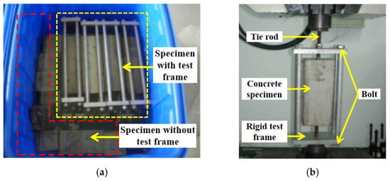
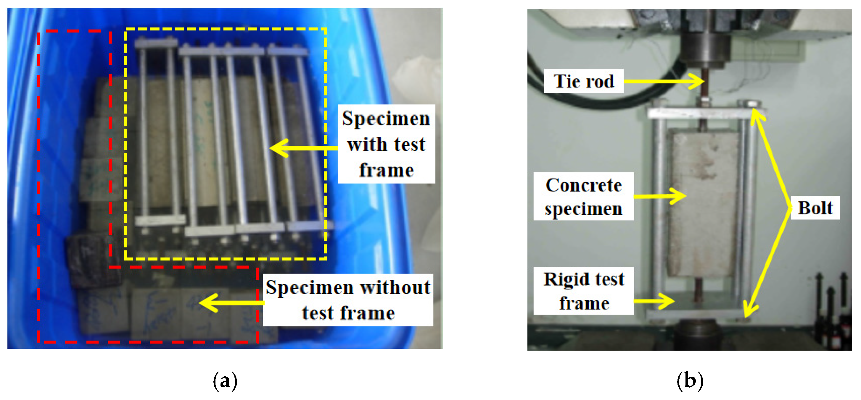
To prepare the concrete specimens, P.O. 42.5 cement was mixed. The specimens were cast and cured for 28 d in a controlled environment before the accelerated multiple-corrosion test. After curing for 28 d, the concrete specimens were baked at T = 80 ± 2 °C for 4 d. After cooling to room temperature, the specimens were immersed in a corrosion solution for 24 h (Figure 1) and placed in a 60 ± 2 °C oven for 13 d. The immersion drying cycle test began at the beginning of soaking in the corrosion solution and continued until the end of drying; one cycle was 14 d. The immersion drying cycle tests were four cycles (two months), eight cycles (four months), 12 cycles (six months), and 24 cycles (12 months) in length. The specimens were removed after the immersion drying cycle test. All test specimens were tested with 1% phenolphthalein ethanol solution to determine the carbonation depth in the concrete.
Figure 1.
Specimen soaking and specimen stress rack: (a) specimen immersed in corrosive solution; (b) specimen tension device.
At the end of the test, the Cl− concentration and compressive strength ratio of the concrete specimens subjected to different corrosion solutions and dry–wet cycle conditions were measured. The Cl− content was tested at mortar depths of 10 mm, 20 mm, 30 mm, 40 mm, and 50 mm from the concrete surface. Salt solutions with a Cl− concentration of 7000 mg/L and 15,000 mg/L were used in the test.
3.2. Effect of Cl− Combined with CO2
Concrete structures in a Cl− environment can also be corroded by CO2. Previous studies [22,23] have shown that CO2 and Cl− diffusion in concrete are strongly correlated. The effect of carbonation on the erosion rate of Cl− has two effects: inhibition and promotion. Carbonation reduces the porosity of concrete, inhibiting the diffusion of Cl−. However, CaCO3 generated by carbonation leads to the redistribution of internal pores in concrete and increases the number of concrete pores, which may lead to faster diffusion of Cl−. Carbonation causes the binding Cl− to undergo a chemical reaction, releasing free water that further accelerates Cl− diffusion.
To simulate the performance of concrete in a Cl− and CO2 composite environment, two groups of concrete specimens with different W/C ratios were immersed in corrosive salt solutions with a Cl− concentration of 7000 mg/L for 24 h and placed in a carbonized box with a CO2 concentration of 2% (T = 60 ± 2 °C, 70 ± 5% humidity) for 13 d of curing. The total testing time was 14 d, considered as one dry–wet cycle. Changes in the neutralization degree and compressive strength of the concrete specimens in four cycles (two months), eight cycles (four months), 12 cycles (six months), and 24 cycles (12 months) were tested in combined Cl− and CO2 conditions.
3.3. Effect of TCC
The carbonation coefficient of a concrete structure is obtained mainly through experiments and statistical analysis. Through experiments, researchers found that the external load could affect the carbonation of concrete by changing its microstructure. Wang et al. [24] reported that the carbonation depth of concrete increased significantly with an increase in load level. External load must be considered in the deterioration of concrete structures.
To study the influence of carbonation shrinkage and dry shrinkage stress on the corrosion resistance of concrete, specimens were subjected to tensile stress at 40% of the ultimate tensile strength, and a dry–wet carbonation cycle test was conducted in a corrosive solution with a Cl− concentration of 7000 mg/L. After the concrete specimens were cured for the specified time, 40% of the ultimate tensile stress was applied to the specimen using a tensile stress testing machine. After tensile loading, the concrete specimens were placed in a corrosive solution with a Cl− concentration of 7000 mg/L for dry–wet cycles lasting four cycles (two months), eight cycles (four months), 12 cycles (six months), and 24 cycles (12 months).
4. Experimental Results and Discussion
4.1. Compressive Strength
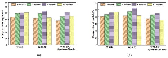
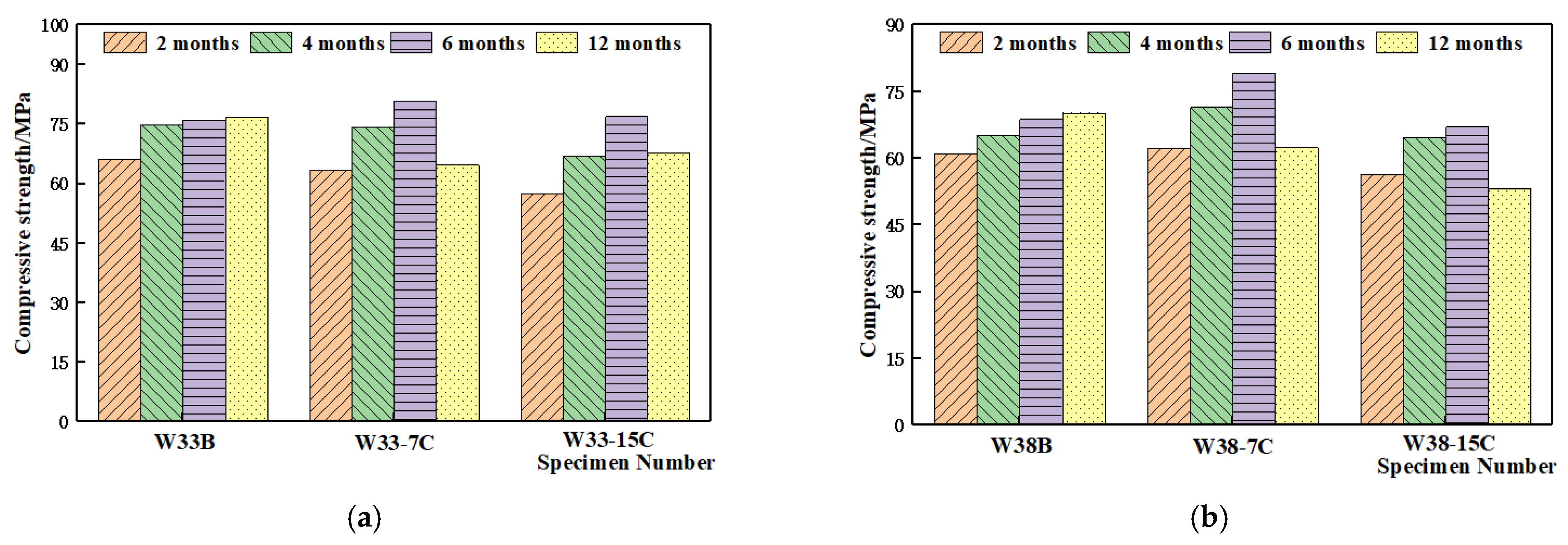
After curing for 28 d, some specimens were used for dry–wet cycles; the remainder continued curing. The concrete specimens were immersed in two corrosive solutions (Cl− concentrations of 7000 mg/L and 15,000 mg/L) for 24 h, and dried for 13 d in a carbonized box with a CO2 concentration of 2%. After the dry–wet cycle test, the compressive strength of the specimens was tested. Specimens of the same age removed from the curing room were also tested for compressive strength. The test results are shown in Figure 2. In Figure 2a, the W/C ratio is 0.33; in Figure 2b, the W/C ratio is 0.38.
Figure 2.
Compressive strength in different test conditions: (a) W/C ratio of 0.33; (b) W/C ratio of 0.38.
In Figure 2a,b, W33B and W38B are standard curing test specimens. W33-7C and W38-7C are the test specimens immersed in a Cl− solution with a concentration of 7000 mg/L solution and dried in a carbonized box. W33-15C and W38-15C are the specimens immersed in a Cl− solution with a concentration of 15,000 mg/L and dried in a carbonized box. The compressive strength of concrete specimens of the same age was lower after 12 and 24 ordinary chlorine soaking cycles than with standard curing but did not decrease significantly with an increase in the number of cycles. The compressive strength of specimens increased significantly after 12 Cl−-CO2 leaching and drying cycles and decreased significantly after 24 Cl−-CO2 leaching and drying cycles in a chloride solution with a Cl− concentration of 7000 mg/L. The compressive strength of specimens soaked in 15,000 mg/L Cl− solution did not change significantly after 12 cycles but decreased significantly after 24 cycles.
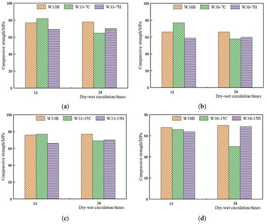
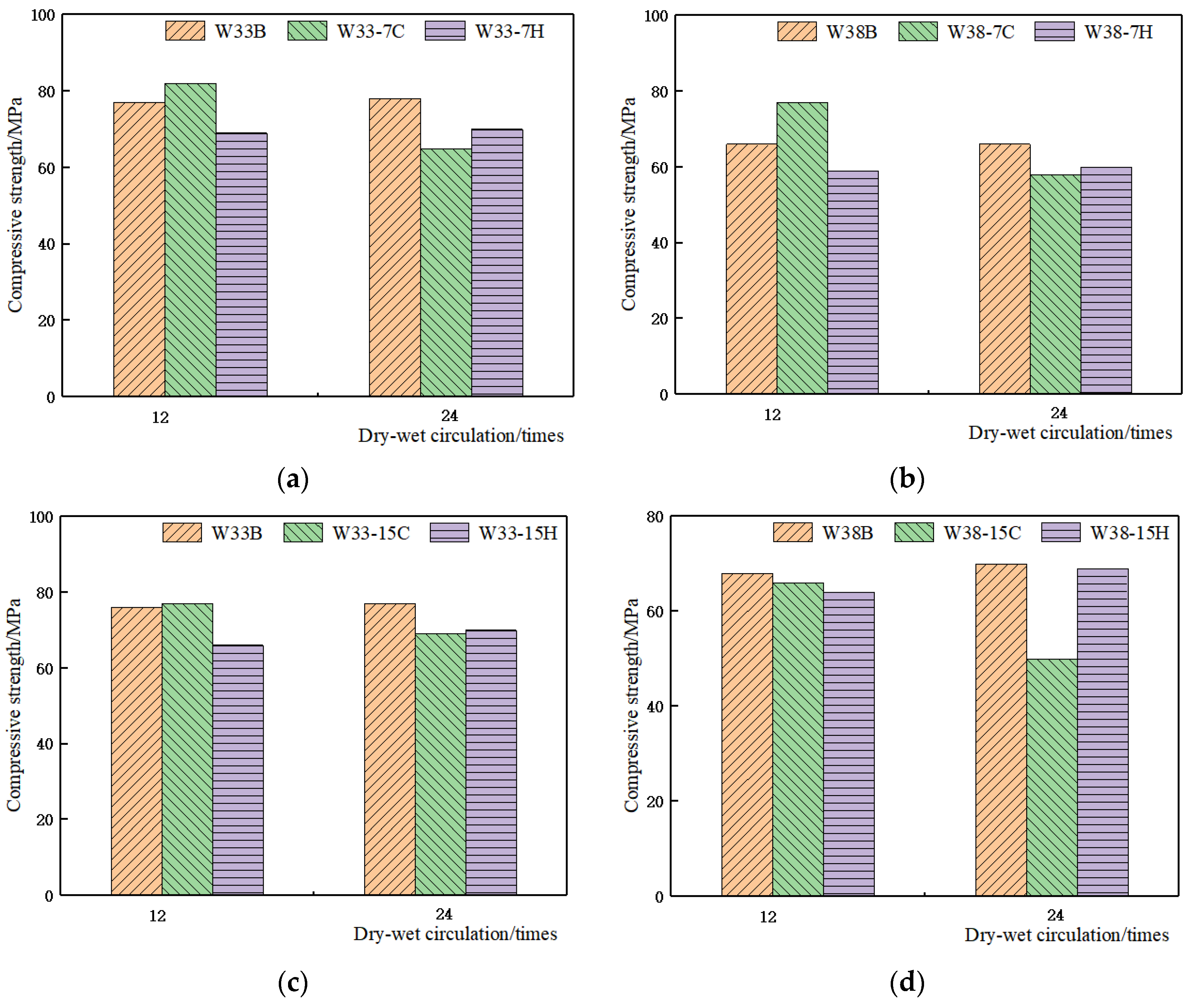
Figure 3 shows the change in compressive strength in different test conditions. W33-7H and W38-7H represent the specimens immersed in a Cl− solution with a concentration of 7000 mg/L and dried in an oven; W33-15H and W38-15H represent the specimens immersed in a Cl− solution with a concentration of 15,000 mg/L and dried in an oven. As seen in Figure 3, the compressive strength of the two groups of specimens with W/C ratios of 0.33 and 0.38 slowly increased with age in standard curing conditions. With at least 12 Cl−-CO2 cycles (six months), the compressive strength of the concrete specimen developed rapidly, especially when immersed in a Cl− solution with a concentration of 7000 mg/L. The compressive strength was greater than the standard curing specimen strength. With 24 Cl−-CO2 cycles (12 months), the compressive strength was significantly less than with standard curing. The strength of the specimens immersed in Cl− solutions with concentrations of 7000 mg/L and 15,000 mg/L increased first and then decreased in the carbonation dry–wet cycle.
Figure 3.
Change in compressive strength in different test conditions: (a) W/C ratio of 0.33 in concentration of 7000 mg/L; (b) W/C ratio of 0.38 in concentration of 7000 mg/L; (c) W/C ratio of 0.33 in concentration of 15,000 mg/L; (d) W/C ratio of 0.38 in concentration of 15,000 mg/L.
4.2. Cl− Penetration
After curing for 28 d, some specimens began dry–wet cycles, and others remained in the standard curing room. The concrete was immersed in two corrosive solutions (Cl− concentrations of 7000 mg/L and 15,000 mg/L) for 24 h, and baked for 13 d in a carbonized box with a CO2 concentration of 2%. For comparison, some specimens were placed in a 60 ± 2 °C oven for 14 d (one cycle). After the dry–wet cycle test was completed, the compressive strength of the specimens was tested. Specimens of the same age were removed from the standard curing chamber to test the compressive strength of specimens in standard curing conditions.
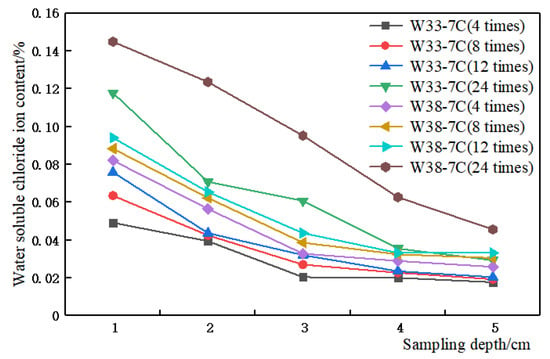
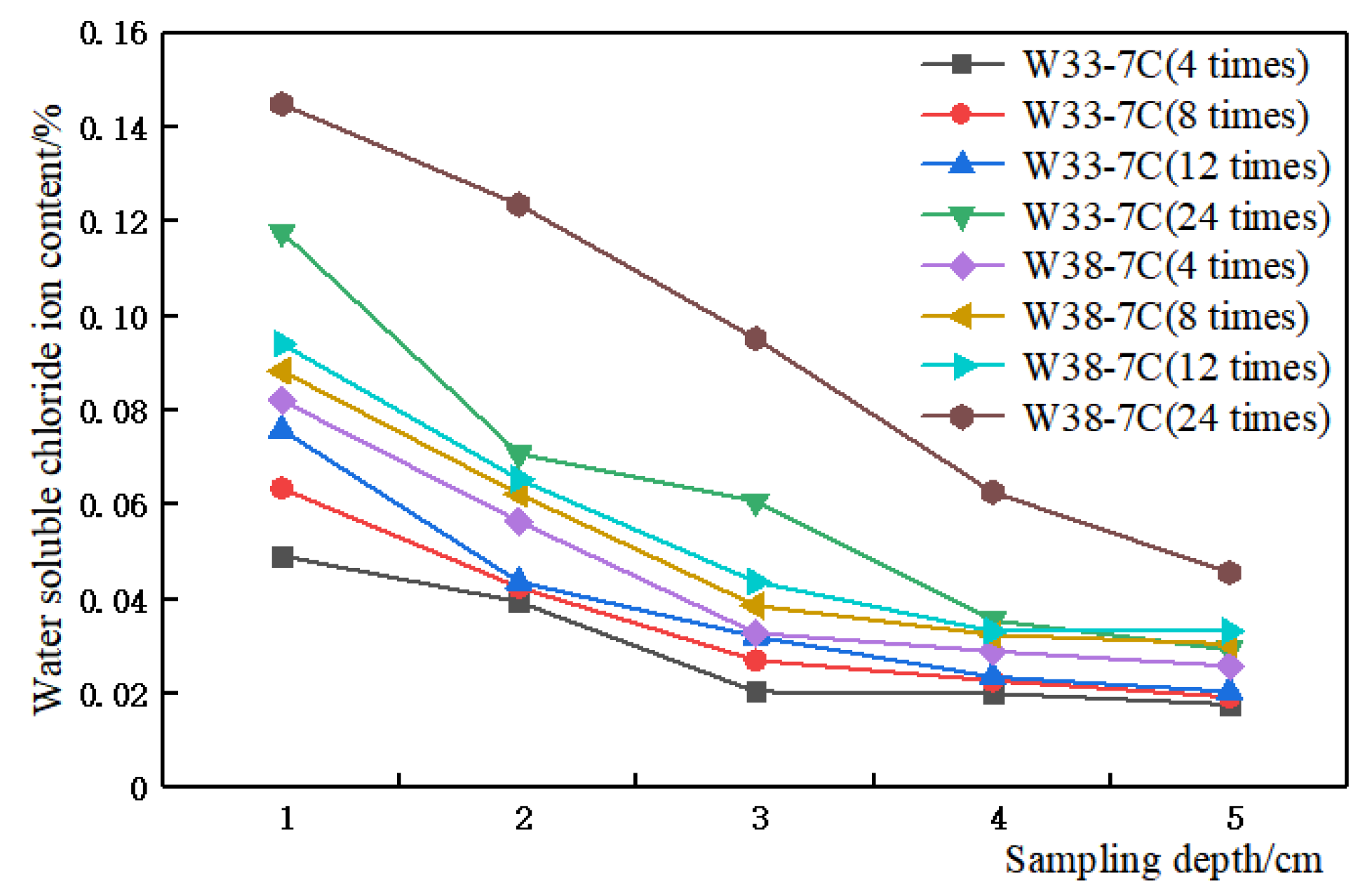
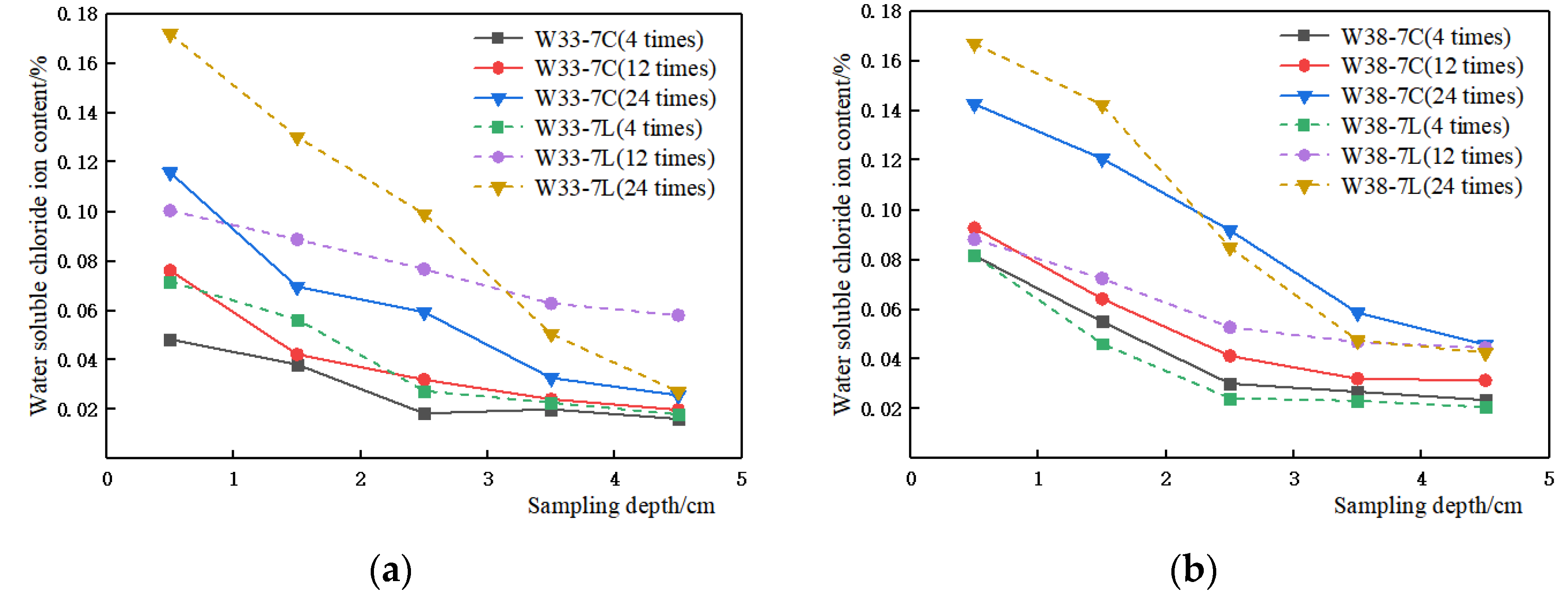
Figure 4 shows the Cl− content in concrete after immersion in a 7000 mg/L salt solution and cyclic drying in a carbonized box for different numbers of cycles. The results show that the Cl− concentration in each layer of concrete gradually increased with an increase in the number of cycles. The formation of bound chloride under carbonation is that the penetration of chloride was weakened by early carbonation curing and chloride ions were limited on the carbonate-rich surface. The Cl− concentration in specimens with a low W/C ratio (0.33) was less than that in specimens with a high W/C ratio (0.38) with the same number of cycles.
Figure 4.
Changes in Cl− permeation in concrete with different Cl− concentrations.
W33-7L and W38-7L in Figure 5 and Figure 6 used tensile stress shelves, applying 40% of the ultimate tensile stress. The results show that the Cl− concentration in each layer of concrete gradually increased with an increase in the number of cycles. The Cl− content in specimens with a low W/C ratio (0.33) was less than that in specimens with a high W/C ratio (0.38) with the same number of cycles.
Figure 5.
Comparison of ultimate bearing capacity in two models with different numbers of cycles: (a) W/C ratio of 0.33; (b) W/C ratio of 0.38.
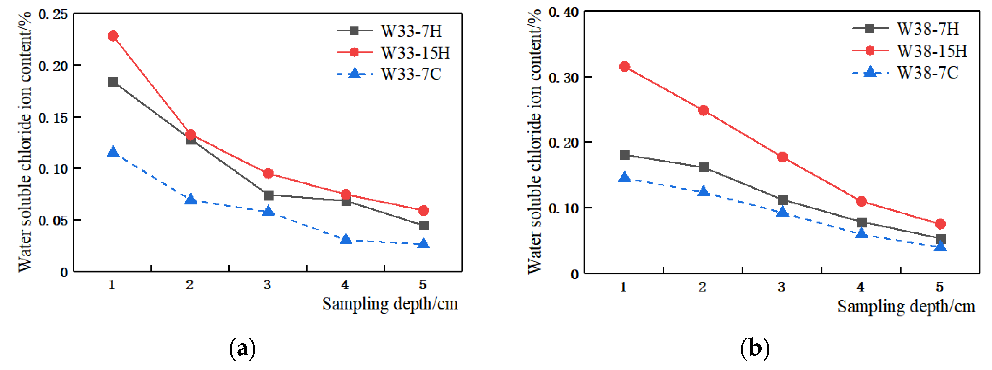
Figure 6.
Comparison of ultimate bearing capacity in two models: (a) W/C ratio of 0.33 under tensile stress; (b) W/C ratio of 0.38 under tensile stress.
Table 3 and Figure 6 show the Cl− concentration at different sampling depths in concrete specimens with different ratios in different test conditions after 24 cycles. The results show that the Cl− concentration in each layer of concrete increased with an increase in Cl− concentration in the salt solution; the Cl− diffusion rate increased significantly. However, after soaking and drying in the carbonation chamber, the Cl− concentration in each layer decreased significantly, indicating that the carbonation of surface concrete hindered the permeation of Cl−. Applying 40% tensile stress, the osmotic pressure velocity of Cl− was accelerated. When 40% tensile stress was applied, the chloride penetration rate of W38-7L accelerated more than that of W33-7L, which had a low W/C ratio (0.33). Tensile stress had a more obvious effect on Cl− penetration acceleration in concrete with a high W/C ratio.
Table 3.
Cl− content in concrete with different ratios (24 cycles).
Figure 6 compares the Cl− permeation with different Cl− solution concentrations and carbonation. The results show that the salt solution concentration had a great influence on the permeation of Cl−, carbonation hindered the permeation of Cl−. This was attributed to the carbonate-rich surface protective layer which was less permeable, and less absorptive, enabling the carbonation cured concrete’s higher resistance to chloride penetration.
Comparing the results for W33-7H and W33-7L in Table 3, it was found that when carbonation and tensile stress were considered simultaneously, the Cl− concentration in the first two layers was similar. Resistance to pressure in the layers of Cl− in concrete increased gradually; as tensile stress was applied, more Cl− permeated the concrete interior, and the effect of a low W/C ratio was more obvious. The effects of tensile stress and carbonation on Cl− penetration opposed each other.
4.3. Carbonation Depth
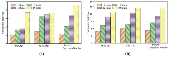
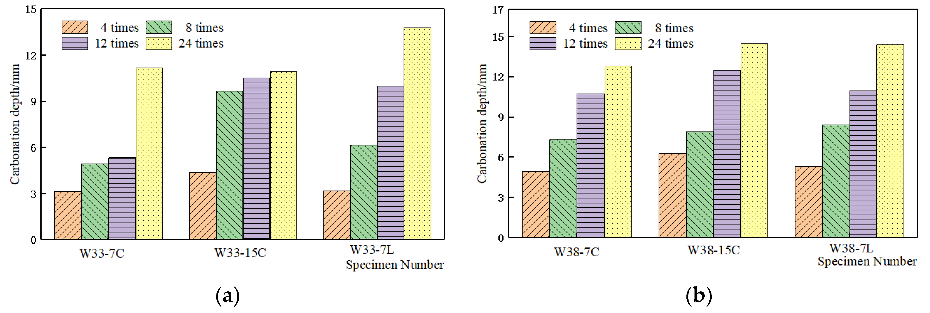
Figure 7 shows the variation in the concrete carbonation depth with an increase in the number of cycles, with Cl− concentrations of 7000 mg/L and 15,000 mg/L and 40% tensile stress.
Figure 7.
Concrete carbonation depth in different test conditions with different numbers of cycles: (a) W/C ratio of 0.33; (b) W/C ratio of 0.38.
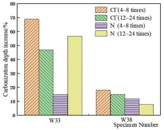
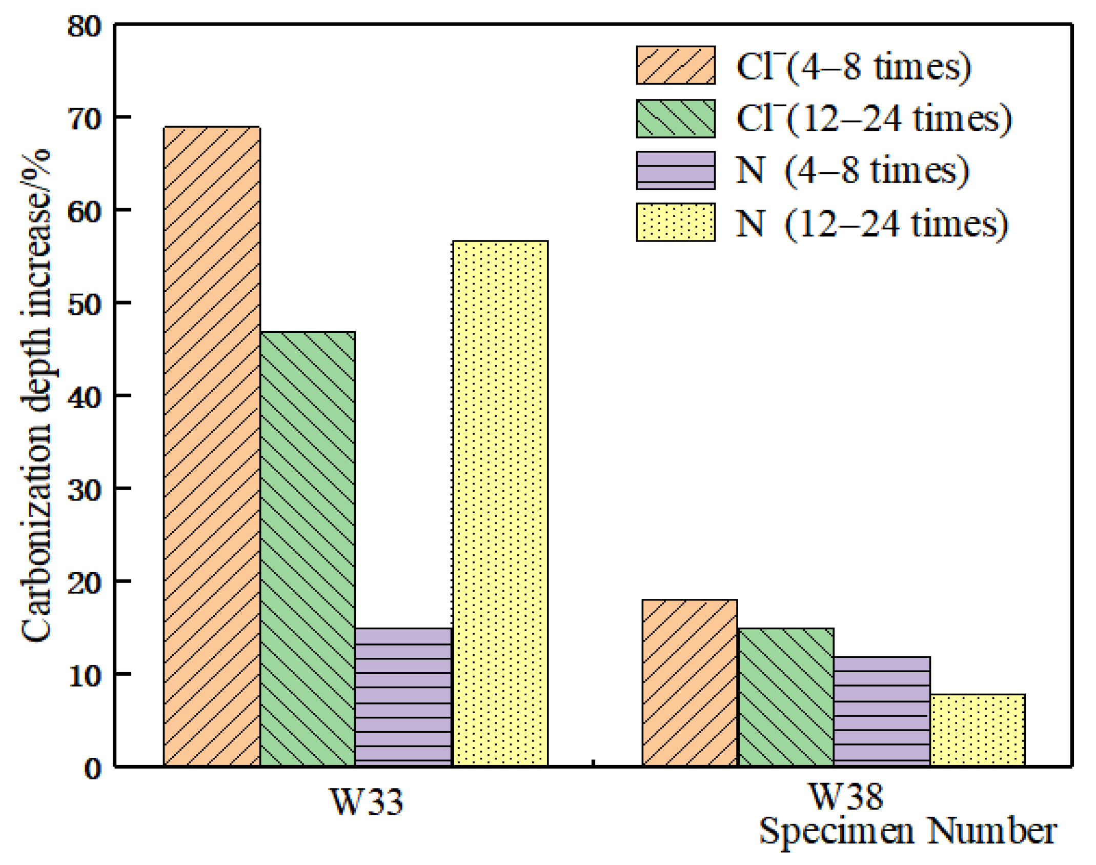
Figure 8 shows the increase in concrete carbonation depth with different numbers of cycles (4–8 cycles in the early stage and 12–24 cycles in the later stage) in two test conditions (tensile stress of increased immersion salt solution concentration applied or not) to distinguish the degree of influence of the two test conditions on concrete carbonation.
Figure 8.
Effects of tensile stress and Cl− on carbonation.
The results show that the carbonation depth of concrete increased with an increase in the number of dry–wet cycles. Tensile stress and Cl− concentration affected the carbonation depth of concrete. With the same number of cycles, the concrete carbonation depth increased with an increase in Cl− concentration of the immersion solution. Similarly, when 40% of the ultimate tensile stress was applied to the specimen, the concrete carbonation depth increased. The effect of the Cl− concentration in the solution on concrete carbonation was significantly greater than that of 40% of the ultimate tensile stress. With a W/C ratio of 0.33, in the early stage of the dry–wet cycles (4–8 cycles), the influence of Cl− concentration on concrete carbonation was significantly greater than that of 40% of ultimate tensile stress. In the later stage (12–24 cycles), the application of 40% of the ultimate tensile stress had a greater influence on concrete carbonation than the Cl− concentration.
5. Multiple Regression Analysis
5.1. Establishment of Multiple Regression Equation
Considering the complexity with multiple factors in the test, three key endurance performance indexes were used for a multiple regression analysis: initial tensile strength, Cl− concentration, and carbonation depth.
The regressive method of stepwise analysis was used to analyze the test data. The regression model used a quadratic multiple regression model to further reflect the interaction of the W/C ratio (X1), Cl− concentration (X2), time (X3), carbon concentration (X4), and tensile stress (X5) on the compressive strength (F), Cl− penetration (C), and carbonation depth of concrete (H). The regression equations of the three dependent variables are shown in Equation (1).
where YF is the regression equation for the compressive strength, YC is the regression equation for the Cl− penetration, and YH is the regression equation for the carbonation depth of concrete.
5.2. Multiple Regression Result
To observe the fitting degree of the regression equation, the modified determination coefficient is generally used as the fitting degree evaluation index for the multiple linear regression equation. The correlation coefficient r, determination coefficient R2, and modified determination coefficient of the regression model are presented in Table 4. It is observed that 2
is close to 1, indicating good fitting of the regression equation.
Table 4.
Analysis of fitting effect.
The purpose of the stepwise regression is to eliminate the indexes with insignificant influence while retaining indexes with significant influence. p represents the significance level; 0.01 < p < 0.05 indicates significant regression. p < 0.01 indicates that the regression is extremely significant. According to YF, it is observed that the compressive strength of specimens is negatively correlated with the square of Cl− concentration, negatively correlated with the carbonation time, and positively correlated with the square of CO2 concentration, which is consistent with the theoretical analysis. The significance of all three factors is less than 0.01.
YC is divided into five layers (Y1, Y2, Y3, Y4, and Y5) for multiple regression corresponding to 0–10 mm, 10–20 mm, 20–30 mm, 30–40 mm, and 40–50 mm. In the 0–10 mm region, the Cl− concentration is positively correlated with the product of the W/C ratio, Cl− concentration, and time, and negatively correlated with the product of the W/C ratio and CO2 concentration, and the product of tension and time. In the 10–20 mm region, the Cl− concentration is positively correlated with the square of the W/C ratio, the product of Cl− concentration and time, the product of time and tensile stress, and negatively correlated with the product of the W/C ratio and Cl− concentration, and the product of the W/C ratio and CO2 concentration. In the 20–30 mm region, the concentration of Cl− is positively correlated with the W/C ratio, the product of Cl− concentration and time, and the square of the tensile stress, and negatively correlated with the product of the W/C ratio and Cl− concentration, the product of the W/C ratio and CO2 concentration, and the product of the W/C ratio and tensile stress. In the 30–40 mm region, the Cl− concentration is positively correlated with the W/C ratio and the product of Cl− concentration and time, and negatively correlated with the W/C ratio, the Cl− concentration, and the square of the time. In the 40–50 mm region, the Cl− concentration is positively correlated with the product of the W/C ratio, Cl− concentration, and time. It is observed that the Cl− concentration in each layer is significantly correlated with the W/C ratio; when a single factor contains the CO2 concentration, there is a significant negative correlation, which is consistent with the theoretical analysis.
In setting up multiple regression equations for different concrete depths, the characteristics of the five equations are observed. All positive correlation factors contain the product of the W/C ratio and Cl− concentration with time. In the two equations for deep layers of concrete such as 30–50 mm, the tensile stress has lost its relevance in the gradual regression process. It is observed from the carbonation depth YH that the W/C ratio is related to product concentration and Cl−, and the W/C ratio is related to time and negatively related to the square of the time. The tensile stress is related to time, consistent with the theoretical analysis. The product of the W/C ratio and the Cl− concentration has a significant p level (0.01–0.05).
6. Conclusions
The purpose of this study was to investigate the durability of reinforced concrete structures in a TCC multiple-corrosion environment. The compressive strength, Cl− penetration, and carbonation properties of concrete were studied in an environment with three coupled factors. The following conclusions can be drawn from the experimental study.
- (1)
- In standard curing conditions, with an increase in curing age, the compressive strength of the two groups of specimens with W/C ratios of 0.33 and 0.38 slowly increased. With up to 12 Cl−-CO2 cycles (6 months), the compressive strength of the concrete specimens developed rapidly. The compressive strength of specimens immersed in a solution with a Cl− concentration of 7000 mg/L was greater than that of specimens subjected to standard curing. However, with 24 dry–wet cycles, the compressive strength was significantly less than that of specimens subjected to standard curing. The strength of samples soaked in 7000 mg/L and 15,000 mg/L salt solutions in the carbonation chamber in dry–wet cycles first increased and then decreased. After 12 cycles of ordinary chlorine-soaking, the compressive strength of the concrete specimens was less than that of standard cured specimens of the same age, but did not decrease significantly with an increase in the number of cycles.
- (2)
- With Cl−-CO2 cycles, the Cl− concentration of each layer of concrete gradually increased with an increase in the number of cycles. The Cl− concentration of specimens with a low W/C ratio (0.33) was less than that of specimens with a high W/C ratio (0.38) with the same number of cycles. After applying tensile stress, the Cl− concentration of each layer in the concrete specimens with a low W/C ratio increased significantly, indicating that more Cl− penetrated the concrete under the action of tensile stress. However, for concrete specimens with a high W/C ratio, the Cl− concentration in each layer did not increase significantly. Cl− concentration had a great influence on the permeation of Cl−; carbonation hindered the permeation of Cl−. The permeation rate of Cl− was accelerated by applying 40% tensile stress. When both carbonation and tensile stress were considered, the Cl− concentration difference in the first two layers was small, indicating that the effects on Cl− penetration produced by tensile stress and carbonation offset each other.
- (3)
- With an increase in the number of dry–wet cycles, the concrete carbonation depth increased continuously. Tensile stress and salt solution concentration affected the concrete carbonation depth. With the same number of cycles, the concrete carbonation depth increased with an increase in the Cl− concentration of the immersion solution. Similarly, the concrete carbonation depth increased after 40% of the ultimate tensile stress was applied to the specimen. The influence of Cl− concentration on concrete carbonation in immersion solution was significantly greater than that of 40% ultimate tensile stress.
- (4)
- A correlation analysis of the durability of concrete structures in multiple-corrosion environments indicated that the main factors affecting the compressive strength of concrete were Cl− concentration and carbonation degree. The main positive correlations for Cl− penetration in each layer of concrete were with the W/C ratio and tensile stress; the tensile stress had little correlation in the deeper concrete layers. The concrete carbonation depth was negatively correlated with the W/C ratio and positively correlated with tensile stress.
Author Contributions
Writing—original draft preparation, methodology, formal analysis, investigation, J.S.; conceptualization, resources, writing—review and editing, X.C. All authors have read and agreed to the published version of the manuscript.
Funding
This research is fully supported by the National Natural Science Foundation of China (52090084) and the Peacock Team Project of Shenzhen (KQTD20200909113951005).
Data Availability Statement
Not applicable.
Conflicts of Interest
The authors declare no conflict of interest.
Abbreviations
| TCC | tensile stress-chloride ion-carbon dioxide |
| Cl− | chloride ion |
| CO2 | carbon dioxide |
| T | temperature |
| W/C | water/cement |
| Cl−-CO2 | chloride ion-carbon dioxide |
References
- Melchers, R. Long-Term Durability of Marine Reinforced Concrete Structures. J. Mar. Sci. Eng. 2020, 8, 290. [Google Scholar] [CrossRef] [Scilit]
- Shah, V.; Bishnoi, S. Carbonation resistance of cements containing supplementary cementitious materials and its relation to various parameters of concrete. Constr. Build. Mater. 2018, 178, 219–232. [Google Scholar] [CrossRef] [Scilit]
- Vu, Q.H.; Pham, G.; Chonier, A.; Brouard, E. Impact of different climates on the resistance of concrete to natural carbonation. Constr. Build. Mater. 2019, 216, 450–467. [Google Scholar] [CrossRef] [Scilit]
- Chang, C.F.; Chen, J.W. The experimental investigation of concrete carbonation depth. Cem. Concr. Res. 2006, 9, 1760–1767. [Google Scholar] [CrossRef] [Scilit]
- Ho, D.W.S.; Lewis, R.K. Carbonation of concrete and its prediction. Cem. Concr. Res. 1987, 35, 1639–1650. [Google Scholar] [CrossRef] [Scilit]
- Papadakis, V.G.; Vayenas, C.G.; Fardis, M.N. A reaction engineering approach to the problem of concrete carbonation. Aiche J. 1989, 35, 1639–1650. [Google Scholar] [CrossRef] [Scilit]
- Niu, D.T.; Sun, C.T. Study on Interaction of Concrete Carbonation and Chloride Corrosion. J. Chin. Ceram. Soc. 2013, 41, 1094–1099. (In Chinese) [Google Scholar]
- Wang, X.Y.; Lee, H.S. A model predicting carbonation depth of concrete containing silica fume. Mater. Struct. 2009, 42, 691–704. [Google Scholar] [CrossRef] [Scilit]
- Jiang, L.; Lin, B.; Cai, Y. A model for predicting carbonation of high volume fly ash concrete. Cem. Concr. Res. 2000, 30, 699–702. [Google Scholar] [CrossRef] [Scilit]
- Carevic, V.; Ignjatovic, I.; Dragaš, J. Model for practical carbonation depth prediction for high volume fly ash concrete and recycled aggregate concrete. Constr. Build. Mater. 2019, 213, 194–208. [Google Scholar] [CrossRef] [Scilit]
- Li, G.; Dong, L.; Bai, Z.A.; Lei, M.; Du, J.M. Predicting carbonation depth for concrete with organic film coatings combined with ageing effects. Constr. Build. Mater. 2017, 142, 59–65. [Google Scholar] [CrossRef] [Scilit]
- Demis, S.; Efstathiou, M.P.; Papadakis, V.G. Computer-aided modeling of concrete service life. Cem. Concr. Compos. 2014, 47, 9–18. [Google Scholar] [CrossRef] [Scilit]
- Collepardi, M.; Marcialis, A.; Turriziani, R. The kinetics of penetration of chloride ions into theconcrete. II Cem. 1970, 67, 157–164. [Google Scholar]
- Mangat, P.S.; Limbachiya, M.C. Effect of initial curing on chloride diffusion in concrete repair materials. Cem. Concr. Res. 1999, 29, 1475–1485. [Google Scholar] [CrossRef] [Scilit]
- Thomas, M.D.A.; Bamforth, P.B. Modelling chloride diffusion in concrete-Effect of fly ash slag. Cem. Concr. Res. 1999, 29, 487–495. [Google Scholar] [CrossRef] [Scilit]
- Wee, T.H.; Wong, S.F.; Swaddiwudhipong, S.; Lee, L. A Prediction method for long-term chloride concentration profiles in hardened cement matrix materials. ACI Mater. J. 1997, 94, 565–576. [Google Scholar]
- Prezzi, M.; Geyskens, P.; Monteiro, P.J.M. Reliability approach to service life prediction of concrete exposed to marine environments. ACI Mater. J. 1996, 93, 544–552. [Google Scholar]
- Liang, M.T.; Wang, K.L.; Liang, C.H. Service life prediction of reinforced concrete structures. Cem. Concr. Res. 1999, 29, 1411–1418. [Google Scholar] [CrossRef] [Scilit]
- Ribeiro, A.B.; Santos, T.; Gonçalves, A. Performance of concrete exposed to natural carbonation: Use of the k-value concept. Constr. Build. Mater. 2018, 175, 360–370. [Google Scholar] [CrossRef] [Scilit]
- Duprat, F.; Vu, N.T.; Sellier, A. Accelerated carbonation tests for the probabilistic prediction of the durability of concrete structures. Constr. Build. Mater. 2014, 66, 597–605. [Google Scholar] [CrossRef] [Scilit]
- Zhu, X.J.; Zi, G.S.; Cao, Z.F.; Cheng, X. Combined effect of carbonation and chloride ingress in concrecte. Constr. Build. Mater. 2016, 110, 369–380. [Google Scholar] [CrossRef] [Scilit]
- Wang, J.; Su, H.; Du, J.S. Influence of coupled effects between flexural tensile stress and carbonation time on the carbonation depth of concrete. Constr. Build. Mater. 2018, 190, 439–451. [Google Scholar] [CrossRef] [Scilit]
- Wang, H.L.; Dai, J.G.; Sun, X.Y.; Zhang, X.L. Time-Dependent and Stress-Dependent Chloride Diffusivity of Concrete Subjected to Sustained Compressive Loading. J. Mater. Civ. Eng. 2016, 28, 04016059. [Google Scholar] [CrossRef] [Scilit]
- Wang, W.; Lu, C.F.; Li, Y.X.; Yuan, G.L.; Li, Q.T. Effects of stress and high temperature on the carbonation resistance of fly ash concrete. Constr. Build. Mater. 2017, 138, 486–495. [Google Scholar] [CrossRef] [Scilit]

Publisher’s Note: MDPI stays neutral with regard to jurisdictional claims in published maps and institutional affiliations. |
© 2022 by the authors. Licensee MDPI, Basel, Switzerland. This article is an open access article distributed under the terms and conditions of the Creative Commons Attribution (CC BY) license (https://creativecommons.org/licenses/by/4.0/).