


Abstract
Selecting an appropriate disc coulter is crucial for reducing the power consumption of no-till seeders, preventing straw from being pressed into seed furrows, improving the soil penetration performance of the disc coulter, and thus minimizing the weight of no-till seeders. This study utilized the quadratic regression orthogonal rotation central composite approach. With the application of EDEM and RecurDyn software, a virtual simulation model of the interaction between a toothed disc coulter and soil was developed. The angle of front serration δ, the angle of rear serration θ, and the number of serrations n were taken as experimental factors. The draft Fv and penetration resistance FN were selected as performance evaluation indicators for parameter combination optimization simulation tests. The results indicated that δ, θ, and n have significant influences on Fv and FN (p < 0.05). When the optimized parameter combinations δ, θ, and n were respectively determined as 16°, 39.1°, and 13, both Fv and FN reached their minimum values. A comparative experimental study was conducted with the optimized toothed disc coulter and six existing disc coulters; under the working conditions of 14.4 km·h−1, both the draft and penetration resistance of the toothed disc coulter are minimized. The draft was 227.5 ± 8.9 N and the penetration resistance was 415.9 ± 5.3 N. Meanwhile, the toothed disc coulter had the highest ratio of soil disturbance area to draft, indicating better soil loosening effects.
1. Introduction
High-performance tillage machinery can create the best soil conditions for crop growth while minimizing power consumption. During operation, tillage machinery consumed substantial energy, most of which was expended to overcome the resistance offered by soil-contacting components [1]. The forces exerted on the soil-contacting components during the tillage process mainly come from the reaction force generated by soil deformation and friction. They are influenced by soil shear strength, soil cohesion, and soil internal friction angle. In practice, issues such as high resistance, high energy consumption, severe adhesion and wear, and incompatibility with agronomic requirements are commonly encountered [2,3]. For instance, soil adhesion can increase plowing resistance by more than 30% [4,5], increase the energy consumption of tillage machinery by 30% to 50%, and decrease the emergence rate of seeding machinery by 5% to 10%. Different parts have different performance optimization needs. Because the resistance generated by the operation of soil-contacting components consumes a lot of power and energy, reducing resistance is always the primary goal in the design of soil tillage components [6,7].
The disc coulter of a no-till seeder is positioned between the seed opener and the inter-row residue clearing device. With a relatively low soil disturbance rate, its main role is to cut through the unworked hard soil before no-till seeding, reducing the resistance faced by the seed opener and ensuring the depth and quality of the seed furrow [8]. The structure of the disc coulter primarily includes smooth, notched, corrugated, and wavy discs. For these four types of disc coulters, when the hardness of unworked soil is high, they require a substantial penetration load to cut through the soil, which leads to increased draft and power consumption [9]. To tackle this problem, Magalhaes [10] designed a toothed disc coulter, which combines the advantages of the low soil entry resistance of sharp openers and the low soil disturbance rate of disc coulters. Each tooth on the disc coulter can be considered as a sharp opener with a variable entry angle [11]. This configuration increases the downward force on the disc coulter during soil entry, thereby enhancing its furrow opening ability. A test on a toothed disc coulter in a soil trough revealed that a disc coulter with a diameter of 610 mm had optimal performance. Bianchini and Magalhaes [12] measured the draft, penetration resistance, torque, and amount of uncut stubble of smooth, notched, and toothed disc coulters in a soil trough filled with sandy clay loam. The tests were conducted at two working depths (80 and 100 mm) and the results showed that the toothed disc coulter performed best. Under the same working conditions, it had smaller draft, penetration resistance, and torque, and was most effective at cutting stubble. In summary, the toothed disc coulter combines the advantages of a conventional circular coulter and a narrow tooth trencher. Its use is highly significant for reducing resistance and consumption in trenching for no-till seeding, as well as for reducing the weight of no-till seeders. However, current studies remain relatively fragmented, lacking systematic exploration of key structural parameters such as serration profile, serration angle and serration quantity. In addition, few studies have conducted direct comparisons on operation resistance among widely used disc coulters.
In recent years, with the rapid development of computer technology, some numerical methods including the finite element method (FEM), Computational Fluid Dynamics (CFD), and the discrete element method (DEM) have been used to simulate the interactions between soil-engaging components and soil in agricultural production. The finite element method can be used to study stress changes, soil deformation, and the interaction forces between soil and soil-engaging components under various soil conditions [13,14]. Karmakar and Kushwaha [15] believe that CFD is feasible for predicting soil fragmentation patterns and soil disturbance area. Zhu used CFD to simulate pressure distribution on the coulter face, studying coulter wear under different working speeds and soil entry depths [16]. FEM and CFD are feasible in some aspects of interaction research between soil and components, but these two numerical simulation methods cannot simulate the soil disturbance around the soil-engaging components. DEM is a definitive numerical method for modeling the dynamic behavior of independently moving particles, and it is a very effective method for solving discontinuity problems. It is very suitable for the study of coulter–soil coupling action [17]. Researchers, through their studies on the motion and force experienced by discrete granular soil particles during the operation of the coulter body, have been able to optimize the coulter structure. This in turn significantly enhances its operational performance and efficiency [18]. Zhang [19] developed a DEM model of the maize root–soil complex and, based on this model, designed and optimized the combination of structural parameters for a disc furrower. Liu [20] developed a DEM-MBD coupled model, revealing the interaction mechanisms between the disc coulter and maize root–soil composites. The aforementioned studies demonstrated that the discrete element method can effectively simulate the operational performance of the disc coulter under field conditions. In addition, the accuracy of particle size settings and particle parameter calibration in discrete element models directly determines the analytical accuracy of the disc coulter–soil interaction process. To improve computational efficiency, existing DEM simulations generally adopt soil particles with relatively coarse sizes, which cannot accurately reflect the operation resistance of disc coulters.
This study, based on DEM-MBD bidirectional coupling technology and using the quadratic regression orthogonal rotation central combination test method, applies EDEM and RecurDyn software to build a virtual simulation model of the interaction between the toothed disc coulter and soil. The aim is to explore the influence of the structural parame-ters of the toothed disc coulter on draft and penetration resistance, optimize the combination of structural parameters, and implement field tests to verify the accuracy of the model. It also compares the toothed disc coulter with the in-service disc coulter, providing a reference for reducing the operation resistance of no-till seeders.
2. Theory
2.1. Toothed Disc Coulter Description
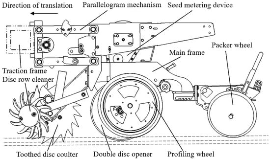
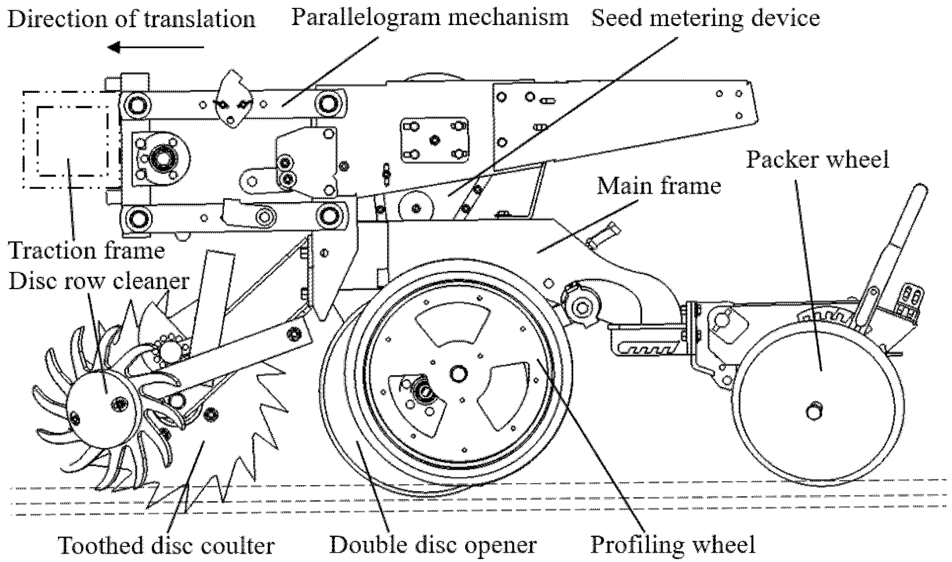
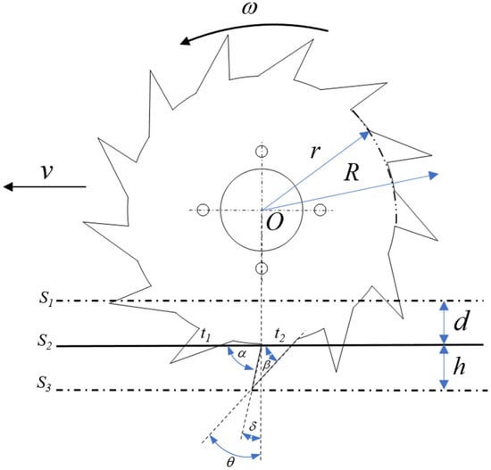
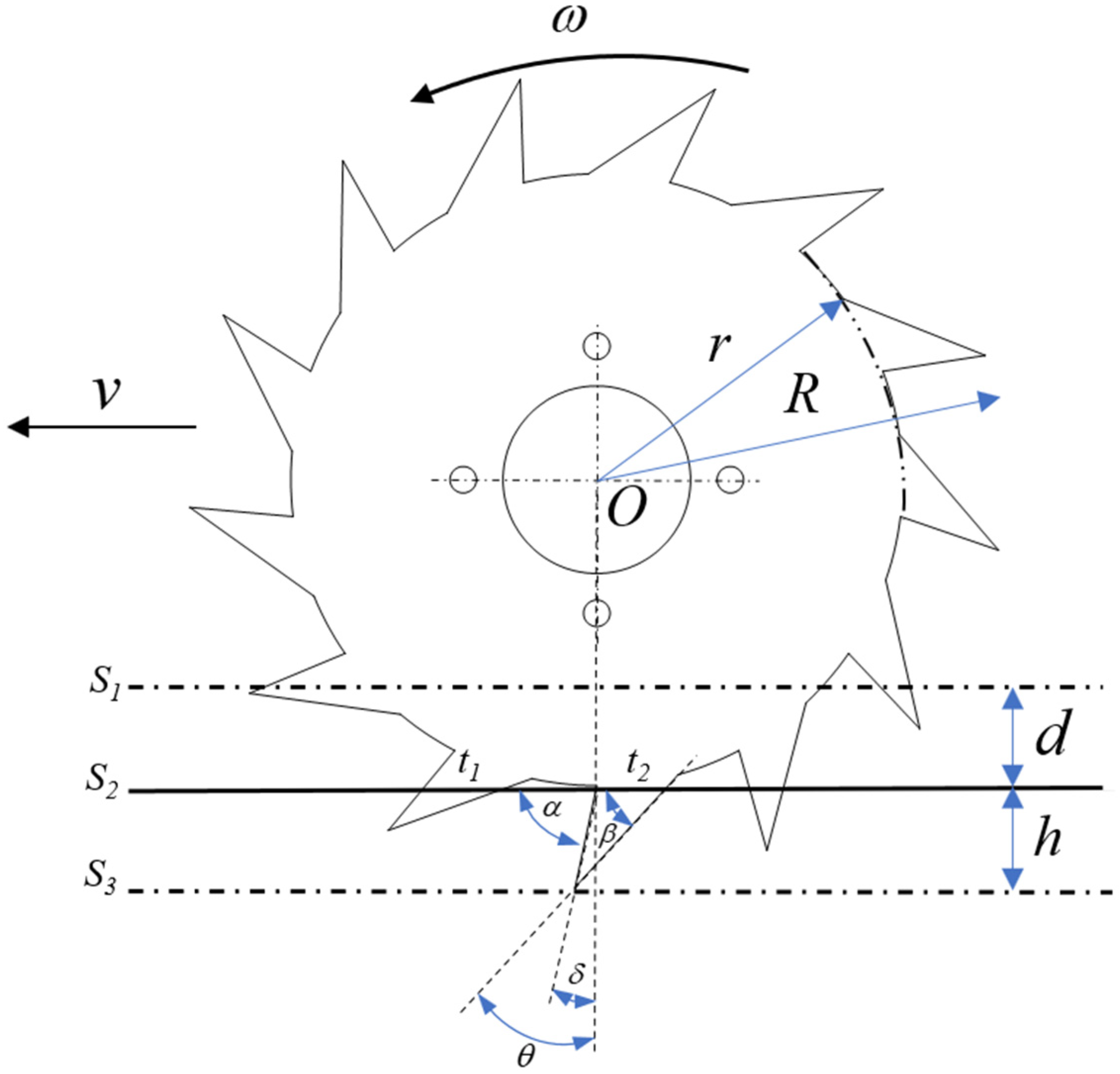
In Heilongjiang Province, China, the no-till seed drill’s disc coulter is attached between the inter-row residue clearance device and the double-disc furrow opener, as depicted in Figure 1. Since the inter-row residue clearance device has to remove corn residue within the seeding band, this study does not consider the impact of residual presence. The toothed disc coulter is made of 65Mn material, and its structure and main parameters are shown in Figure 2. The primary structure and operational parameters of the toothed disc coulter, along with their values, are listed in Table 1.
Figure 1.
Configuration diagram of the toothed disc coulter on the no-till seed drill unit.
Figure 2.
Structure of the toothed disc coulter.
Table 1.
Toothed disc coulter structure and operating parameters.
2.2. Principle Analysis
The working process of the toothed disc coulter in soil is a complex mechanical interaction. To effectively accomplish stubble cutting and furrow opening operations, two fundamental conditions must be simultaneously met: first, sufficient penetration pressure must be applied to ensure the coulter can penetrate the soil smoothly; second, the soil must provide adequate reactive force to maintain stable rotation of the coulter. Based on the classical soil cutting theory proposed by Reece [21], the mechanical characteristics of the toothed disc coulter can be quantitatively analyzed. Specifically, the toothed disc coulter can be simplified as a sharp furrow opener model with a constant width and adjustable soil entry angle. Based on this, it can be deduced that the draft experienced by the plow blade during operation can be expressed by Equations (1)–(4) [20].
where γ—soil bulk density, g·cm−3; g—gravitational acceleration, m·s−2; d—working depth of plow blade, m; c—soil cohesion, kPa; q—soil adhesion, kPa; w—plowing blade width, m; Nγ, Nc, Nq—coefficients depending on the soil friction coefficient, plow blade geometry, and the strength characteristics of the plow blade and soil; Fvt —the component of Fv in the direction perpendicular to ; α—the angle between the front of the digging blade and the horizontal direction, °; β—the angle between the back of the digging blade and the horizontal direction, °; φ—friction angle between soil and metal, °; and ϕ—internal friction angle of soil, °.
The resistance encountered by the toothed disc coulter blade as it penetrates the soil is determined by Equation (5). The resistance experienced by the toothed disc coulter blade as it pierces through the straw layer is represented by the product of the pressure required for the blade to cut through a single layer of straw and the thickness of the straw layer, which is determined by Equation (6).
where C—soil resistance to cone penetration, kPa; Sp—circular plow blade teeth penetration area, m2; and Fesp—the pressure required for cutting a unit area of straw with blade teeth, N·m−2.
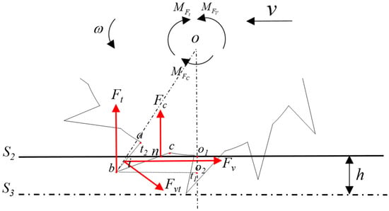
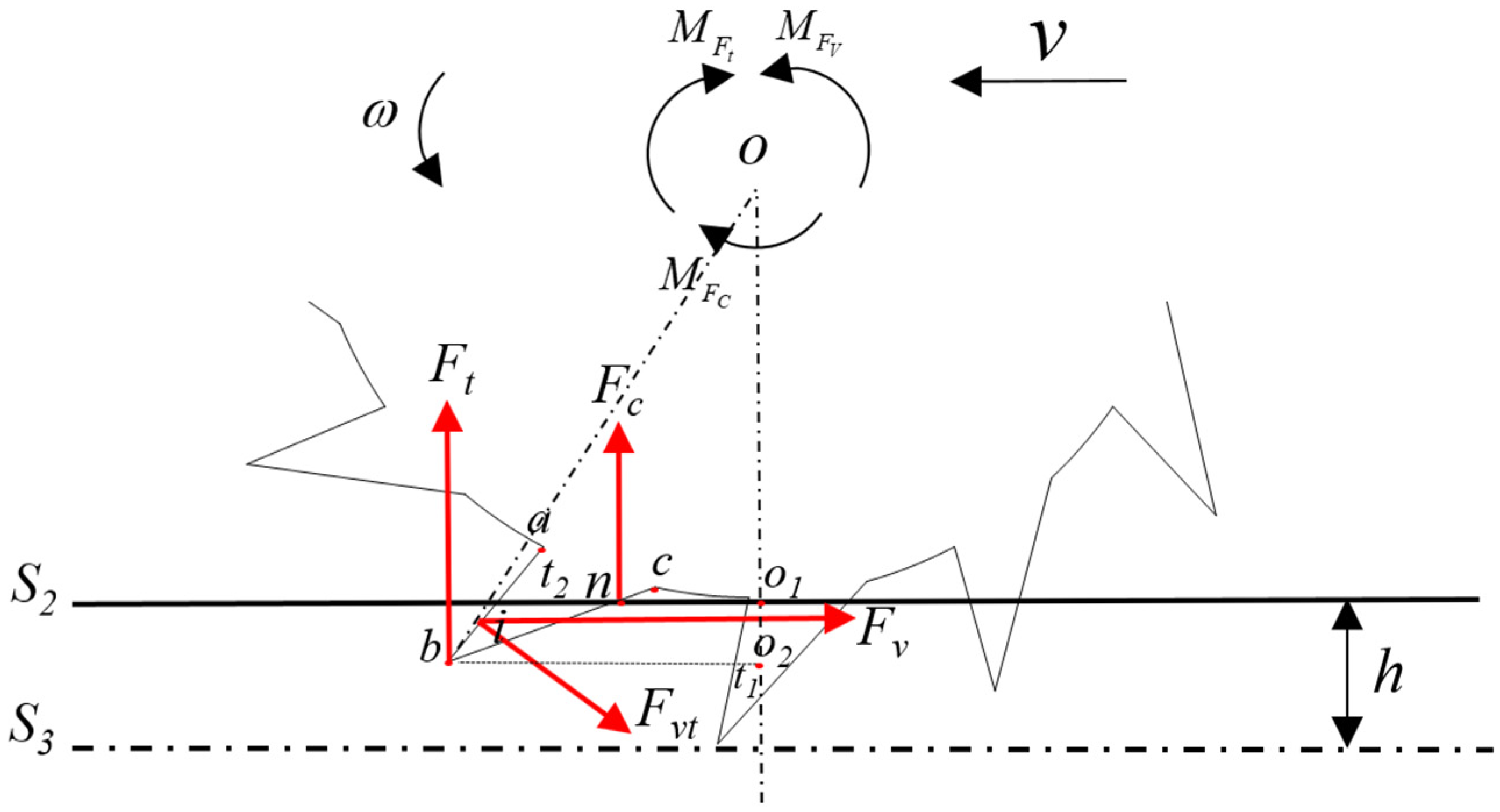
The draft Fv impedes the advancement of the toothed disc coulter and generates a moment MFv, causing the disc coulter to rotate. The resistance Fc, encountered as the disc coulter’s teeth pierce through the straw layer, and the resistance Ft, experienced as the coulter’s teeth penetrate the soil, respectively produce moments MFc and MFt that hinder the rotation of the coulter. The condition under which the disc coulter can rotate normally to cut through stubble and soil is shown in Equation (7), where the frictional force between the soil and the sidewall of the disc coulter is neglected. MFv1 and MFv2 are calculated based on the geometric configuration illustrated in Figure 3. Fv1 and Fv2 represent the maximum reaction forces that the soil can provide to the coulter blades t1 and t2 of the disc plow.
where —the length of the line segment from point o to point i, mm; —the length of the line segment from point o1 to point n, mm; and —the length of the line segment from point o2 to point b, mm.
Figure 3.
Force analysis diagram of the toothed disc coulter.
3. Materials and Methods
3.1. Optimization Experiment of Toothed Disc Coulter Structure Parameters
3.1.1. Establishment of a Soil Discrete Element Model Based on EDEM Software
Given the soil type at the experimental site, the Hertz–Mindlin with Bonding model from EDEM 2020 (DEM Solutions Ltd., Edinburgh, UK) was selected as the contact model for soil particles [22,23]. This model features cylindrical bonds between soil particles, simulating the adhesion between cohesive soil particles, and it can withstand a certain amount of force and torque [24,25]. Particle shape and size are often considered key parameters in discrete element modeling. Existing research suggests that, under the Hertz–Mindlin with Bonding model, the shape of the soil particle units has little effect on the interactions between soil particles [26]. Thus, this study employs basic spherical particles from EDEM as soil particle units. In discrete element simulation, a decrease in particle size leads to a geometric increase in simulation runtime [27]. However, if the particle size is too large, it affects the simulation results. Considering the computational capabilities of HP Z8 G4 Workstation used in this study, the radius of the soil particle model was set to 3 mm.
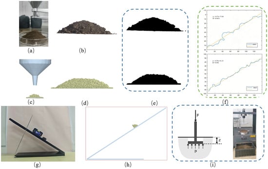
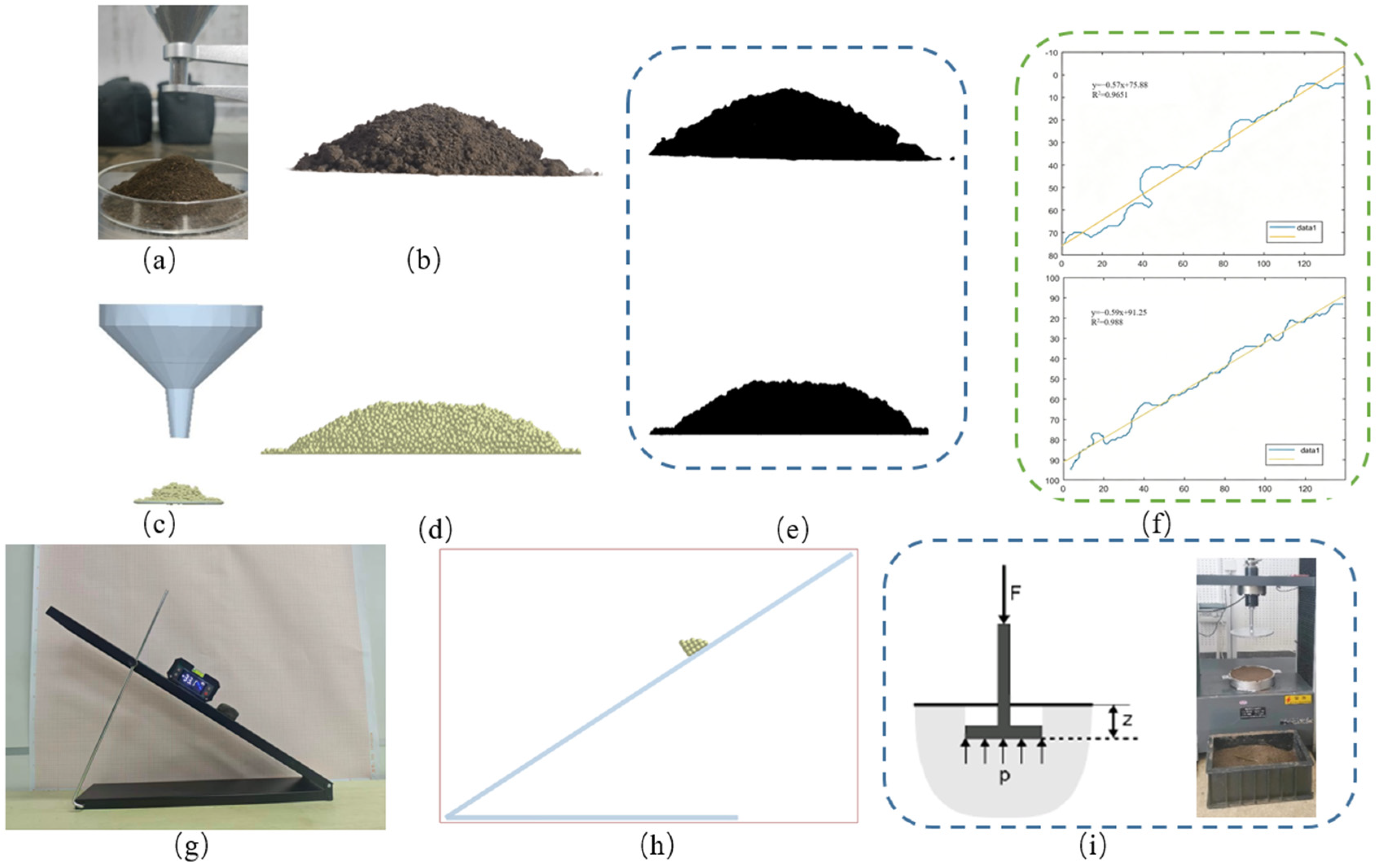
The model parameters in EDEM mainly include material parameters and contact parameters. Material parameters primarily include the density, Poisson’s ratio, and shear modulus of the soil and the toothed disc coulter. The toothed disc coulter was made of 65Mn steel, and its density, Poisson’s ratio, and shear modulus were referenced from the literature [28]. The soil material parameters were obtained through field tests at the soil sampling site. The contact parameters mainly include the coefficient of restitution, the coefficient of dynamic friction, and the coefficient of static friction between the interacting materials. The coefficient of restitution was obtained from the literature [29,30]. The coefficient of dynamic friction between the soil and 65Mn steel was calibrated through sliding friction tests and EDEM simulations. The procedure is shown in Figure 4. The bonding parameters of the Hertz–Mindlin with Bonding model include the normal stiffness of the bond, the tangential stiffness of the bond, the normal critical stress of the bond, the tangential critical stress of the bond, and the bonding radius. According to the method of reducing the number of parameter calibrations [31,32], the normal stiffness was set equal to the tangential stiffness, and the normal critical stress was set equal to the tangential critical stress. Previous studies had shown that the particle motion behavior under the Hertz–Mindlin with Bonding model is insensitive to bonding stiffness parameters [33], and the normal and tangential bonding stiffnesses are both set to 5 × 10⁷ N/m3. The bonding radius is closely related to the soil moisture content, and its value is determined by the moisture content and soil particle radius [34,35]. The normal and tangential critical stresses of the bonding were obtained from the uniaxial compression test, and the test procedure is shown in Figure 4. The EDEM simulation parameters are shown in Table 2.
Figure 4.
Contact parameter calibration test. (a) Stacking angle physical test. (b) Soil physical accumulation diagram. (c) Stacking angle simulation test. (d) Soil simulation accumulation diagram. (e) Binary processing. (f) Accumulation boundary fitting diagram. (g) Sliding friction physical test. (h) Sliding friction simulation test. (i) Uniaxial compression test.
Table 2.
EDEM model simulation parameters.
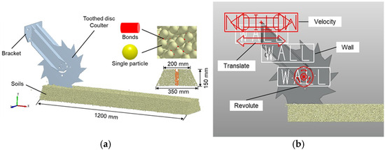
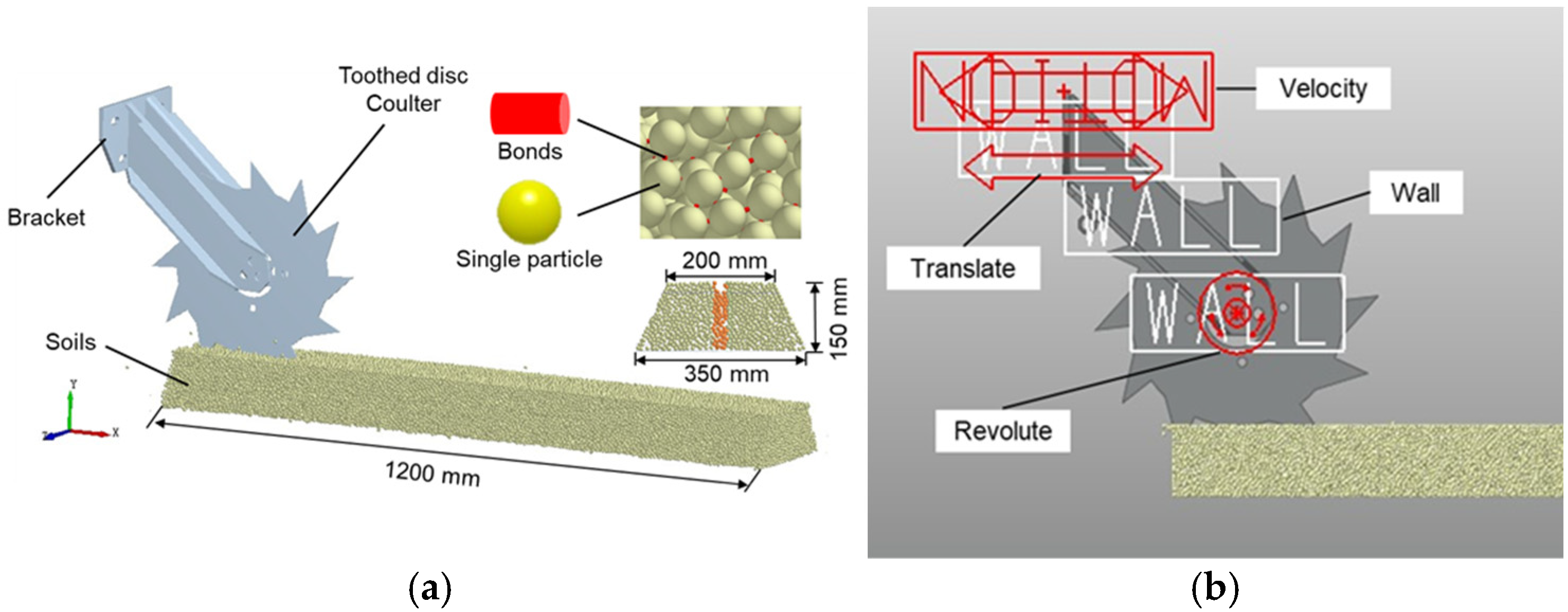
During the experiment, the toothed disc coulter’s penetration depth was set at 50 mm, and the soil model height was chosen as 150 mm [36]. As the disc coulter rolls and cuts through soil, the amount of soil disturbance is small. To improve the simulation efficiency, a smaller width can be set for the soil model. In SolidWorks 2017 software, a trapezoidal ridge filled with soil particles was created, with a cross-section of 1200 × 200 × 350 × 150 mm (length × upper base × lower base × height). After setting the parameters, a soil groove was created through the dynamic particle accumulation method of the particle factory. Once particle generation was complete, the particles underwent settlement and bonding. The soil groove model is shown in Figure 5a.
Figure 5.
Model establishment: (a) soil groove model; (b) kinematic model of toothed disc coulter.
3.1.2. Establishment of Toothed Disc Coulter Kinematic Model
A 1:1 scale model of the toothed disc coulter imported into RecurDyn V9R4 (FunctionBay, Inc., Seongnam-si, Gyeonggi-do, Republic of Korea) via a STEP format file. A revolute joint was added between the disc coulter and the frame, and a translational joint was added to the frame (Figure 5b). A velocity drive was added to the moving pair, operating at a speed of 14.4 km·h−1 along the longitudinal direction of the soil groove. A ‘wall’ was added to the toothed disc coulter and the ‘wall’ file was exported.
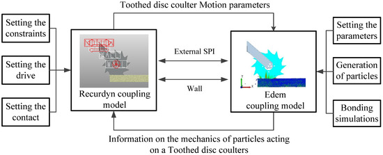
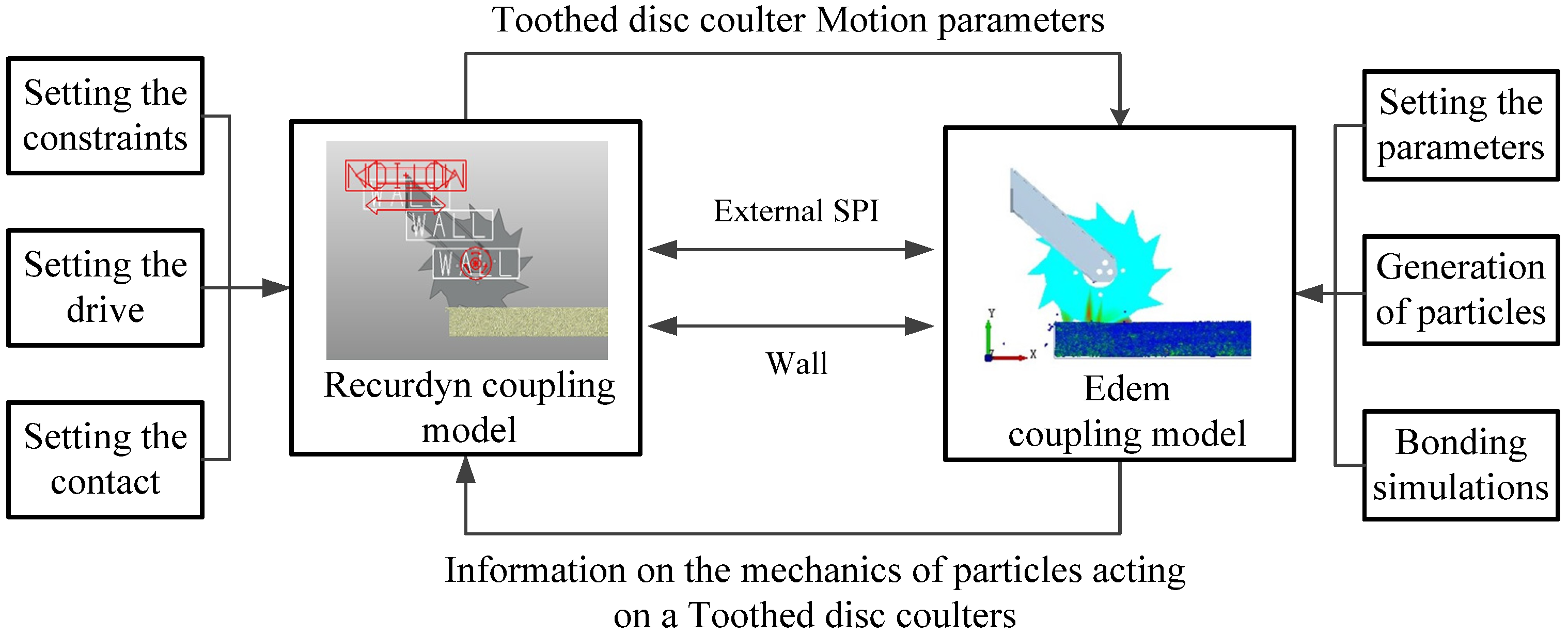
3.1.3. EDEM-RecurDyn Bidirectional Coupling
The kinematic simulation software RecurDyn V9R4 and the discrete element simulation software EDEM exchange data via a ‘wall’ format file. The two software platforms are bidirectionally coupled via the external SPI interface, achieving real-time data exchange between soil particles and the geometric model. In EDEM 2020, the simulation time step was set to 15.382%, and the data storage interval was 0.01 s. In order to maintain the time synchronization between multi-body dynamics and discrete element simulation, the EDEM simulation duration was adjusted to 2 s, the external SPI coupling interface module of EDEM was activated, and the coupling was started and completed. The global coordinate systems of the two systems remain consistent, with the positive direction of the z-axis as the draft direction of the toothed disc coulter. The principle of EDEM-RecurDyn bidirectional coupling is shown in Figure 6.
Figure 6.
Schematic diagram of EDEM-RecurDyn bidirectional coupling principle.
3.1.4. Simulation Experimental Design
A three-factor, five-level, second-degree regression orthogonal rotation combination experiment method was employed. The factors under consideration were the angle of front serration δ, the angle of rear serration θ, and the number of serrations n. The evaluation metrics were the draft FV and the penetration resistance FN. The serrations of the disc coulter acted as acute cutting structures with active soil penetration performance. However, during operation, the disc coulter rotates, causing the entry angle of the disc coulter teeth to vary over time. This is mainly determined by the size of the angle of front serration. Prior to the test, the discrete element soil parameters were calibrated in advance. The calibration process is shown in the following figure and has been supplemented in the revised manuscript.
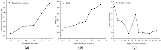
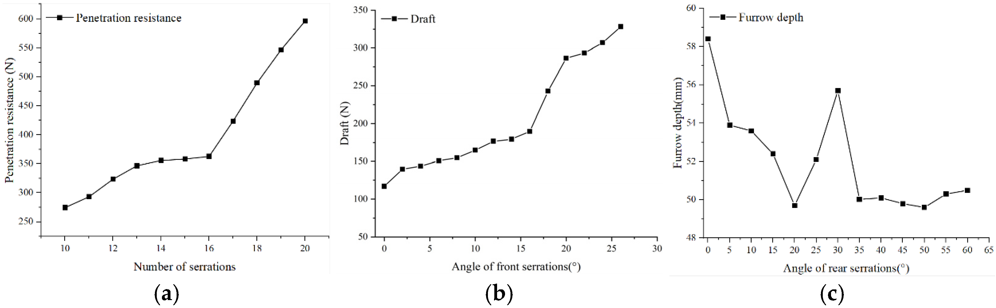
The number of serrations: With a disc diameter of 460 mm, at least two serrations should keep penetrating the soil at any moment to guarantee the steady rotation of the toothed disc coulter. Therefore, the minimum level of the number of serrations was set to 10 in this study. A larger number of serrations increases the cutting frequency, while excessive serrations weaken the soil penetration performance of the toothed disc and raise the penetration resistance. Taking the front serration angle of 16° and the rear serration angle of 39°, single-factor simulation tests were conducted with the number of serrations ranging from 10 to 20. The variation curve of penetration resistance against the number of serrations is shown in Figure 7a. The penetration resistance tended to be stable when the number of serrations was 14–16 and increased dramatically as the number of serrations exceeded 16.
Figure 7.
Results of single-factor experiments: (a) variation in penetration resistance with the number of serrations; (b) variation in draft with the angle of front serration; and (c) variation in furrow depth with the angle of rear serration.
The angle of front serration: The serrations of the toothed disc coulter are equivalent to acute-angle openers and possess the function of active soil penetration. Due to the continuous rotation of the disc during operation, the actual penetration angle of the coulter teeth changes dynamically, which is mainly determined by the angle of front serration. When the angle of front serration is close to 0°, the disc presents the optimal penetration performance and the minimum penetration resistance. An excessively large angle will weaken the soil penetration capacity of the disc. Greater vertical pressure is required to press the disc into the soil, thereby causing a sharp increase in horizontal resistance. Referring to the general penetration angle of 15°–25° for acute-angle openers, the upper limit was adopted to carry out single-factor simulation tests on the angle of front serration and horizontal resistance, and the results are shown in Figure 7b. In the range of 0°–16°, penetration resistance rises slowly with the increase in the angle of front serration. When the angle of front serration exceeds 16°, penetration resistance increases sharply, and the growth rate gradually slows down after exceeding 20°. Therefore, the selection range of the angle of front serration is determined as 0°–16°.
The angle of rear serration: A smaller angle of rear serration reduces the compaction of the furrow bottom caused by the toothed disc coulter, which is conducive to decreasing vertical pressure and soil compaction in the furrow. However, an excessively small angle of rear serration easily triggers soil throwing at high operating speeds. Advanced soil backfilling results in an uneven furrow bottom and weakens the consistency of furrow depth. Whereas, an excessively large angle of rear serration increases the contact area between the disc and soil. Geometrically, when the angle of rear serration exceeds 45°, the circumferential distribution of serrations will be restricted. Taking the angle of rear serration as the experimental factor and the average furrow depth as the evaluation index, field tests were carried out under the conditions of an operating speed of 14.4 km·h−1 and a penetration depth of 50 mm. The test results are presented in Figure 7c. When the angle of rear serration ranged from 0° to 35°, the furrow depth fluctuated significantly. This phenomenon was mainly attributed to soil throwing and premature backfilling induced by the small rear serration angle, which led to unstable furrow depth. When the angle of rear serration was higher than 35°, the fluctuation of furrow depth gradually weakened. Consequently, the reasonable range of the angle of rear serration was determined as 35°–45°. The level coding of the experimental factors is shown in Table 3. Design Expert 8.0.6 software (StatEase, Inc., Minneapolis, MN, USA) was used for the design of the experimental scheme and optimization of the results. Both EDEM and RecurDyn software can record real-time force data in horizontal and penetration directions during the interaction process between the disc coulter and the soil (i.e., draft and penetration resistance). The evaluation metrics measurements were taken as the average values within the stable range of the draft and penetration resistance of the disc coulter.
Table 3.
Experimental factor level encoding chart.
3.2. Comparative Performance Test of Disc Coulter
In order to validate the accuracy of the simulation model, a toothed disc coulter with optimal structural parameters was manufactured. The parameters included an outer diameter of 460 mm, an inner diameter of 360 mm, an angle of front serration 16°, a rear serration angle of 39.1°, and 13 serrations. This disc coulter was selected along with seven representative types of disc coulters used in production for a comparative field experiment.
3.2.1. Site Description
The experiment was conducted from 2 June to 6 June 2022, at the Xiangyang Experimental Base of Northeast Agricultural University in Heilongjiang Province, China. The soil type was primarily sticky black soil, and the average strength and moisture content of the soil at 0–50 mm depth were 16.7 kg/cm2 and 23.4%.
3.2.2. Equipment Description
- (1)
- Seven types of disc coulter
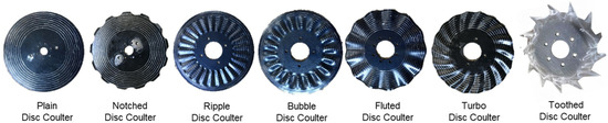
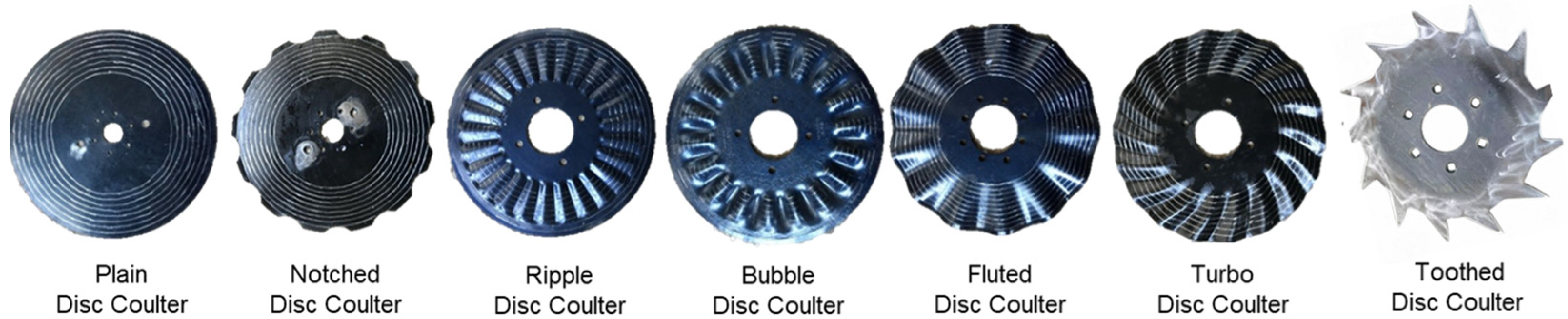
The seven disc coulters under study included the plain disc coulter, the notched disc coulter, the ripple disc coulter, the bubble disc coulter, the fluted disc coulter, the turbo disc coulter, and the toothed disc coulter. The geometric parameters of these are shown in Figure 8 and Table 4, respectively.
Figure 8.
Seven types of disc coulter.
Table 4.
Geometric parameters of disc coulter.
- (2)
- Field telemetric instrument for agricultural machinery kinematic parameters
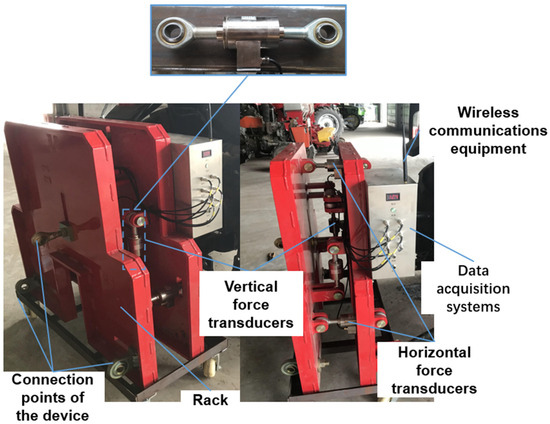
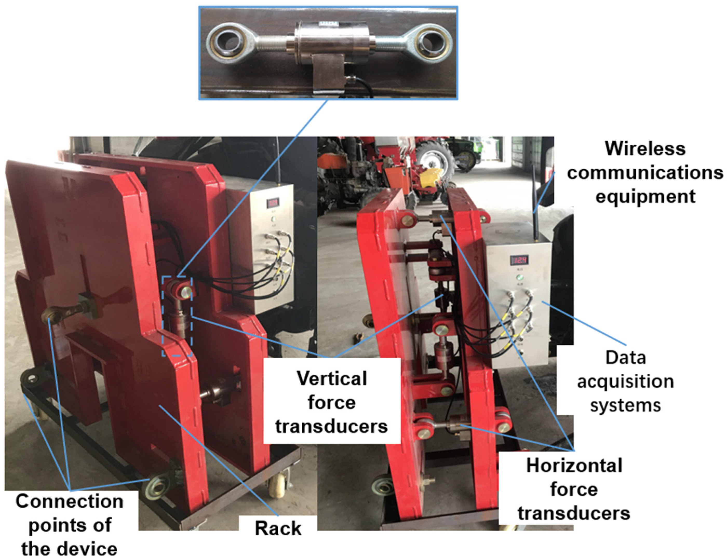
Draft and penetration force were measured with a field machinery dynamical parameter telemetry system. The telemetry system comprised a frame, a BK-1BZF tension–compression sensor (China Academy of Aerospace Aerodynamics, Beijing, China), a USB66530 data acquisition system (National Instruments, Austin, TX, USA), a SZ02-USB-2K wireless data transmission device (Shanghai Shunzhou Network Technology Co., Ltd., Shanghai, China), and a computer equipped with data collection software, as shown in Figure 9.
Figure 9.
Field telemetric instrument for agricultural machinery kinematic parameters.
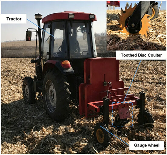
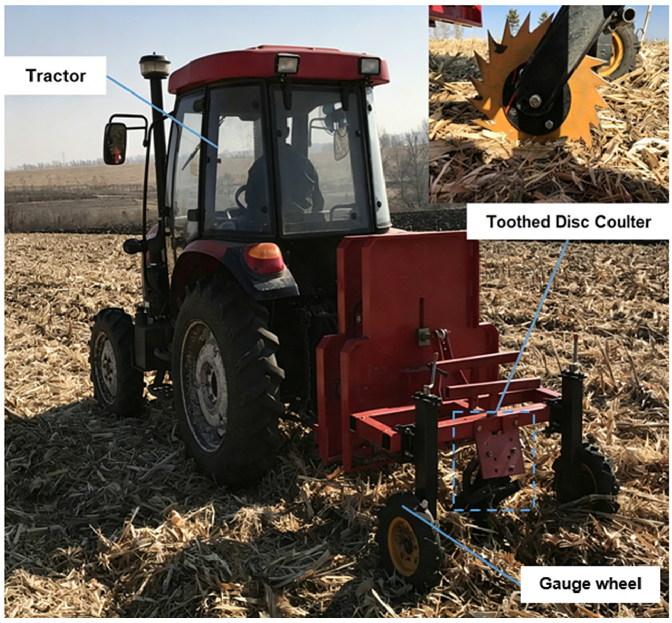
The experiment utilized a Dongfanghong MF604 wheel tractor (YTO Group Corporation, Luoyang, China) as the power source. The disc coulter was installed on a frame equipped with two gauge wheels used for controlling the plowing depth. The frame was connected to a custom-made force measurement device through a three-point suspension, which in turn was linked to the tractor, as shown in Figure 10.
Figure 10.
Field testing setup.
3.2.3. Experimental Design
The experiment was designed using a completely randomized factorial design. The experimental factors included seven types of coulters and three operation speeds (10.8, 12.6, and 14.4 km·h−1), resulting in 21 combinations. Each treatment was replicated 3 times, making a total of 63 test plots. During the experiment, the tractor maintained a uniform speed, the disc coulter penetrated to a depth of 50 mm, and the operation covered a straight-line distance of 30 m. To enhance the accuracy and scientific validity of the test data, buffer zones were established at both ends of the plot for tractor acceleration and deceleration, ensuring the tractor maintained a constant speed within the plot.
3.2.4. Measurements
All measurements were taken at three random locations within each test plot.
- (1)
- Draft and penetration force
The telemetry system was calibrated before the field experiment. The draft and penetration force data were collected in real-time on the computer during the operation of the disc coulter. The force signal was recorded at a frequency of 65 Hz by the data acquisition system during the operation of the disc coulter.
- (2)
- Parameters of the furrow profile cross-section
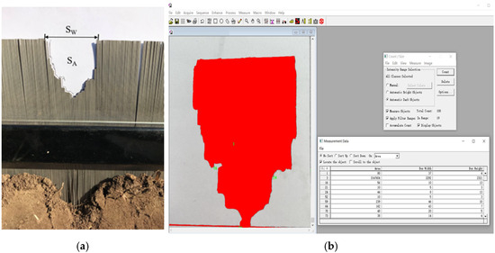
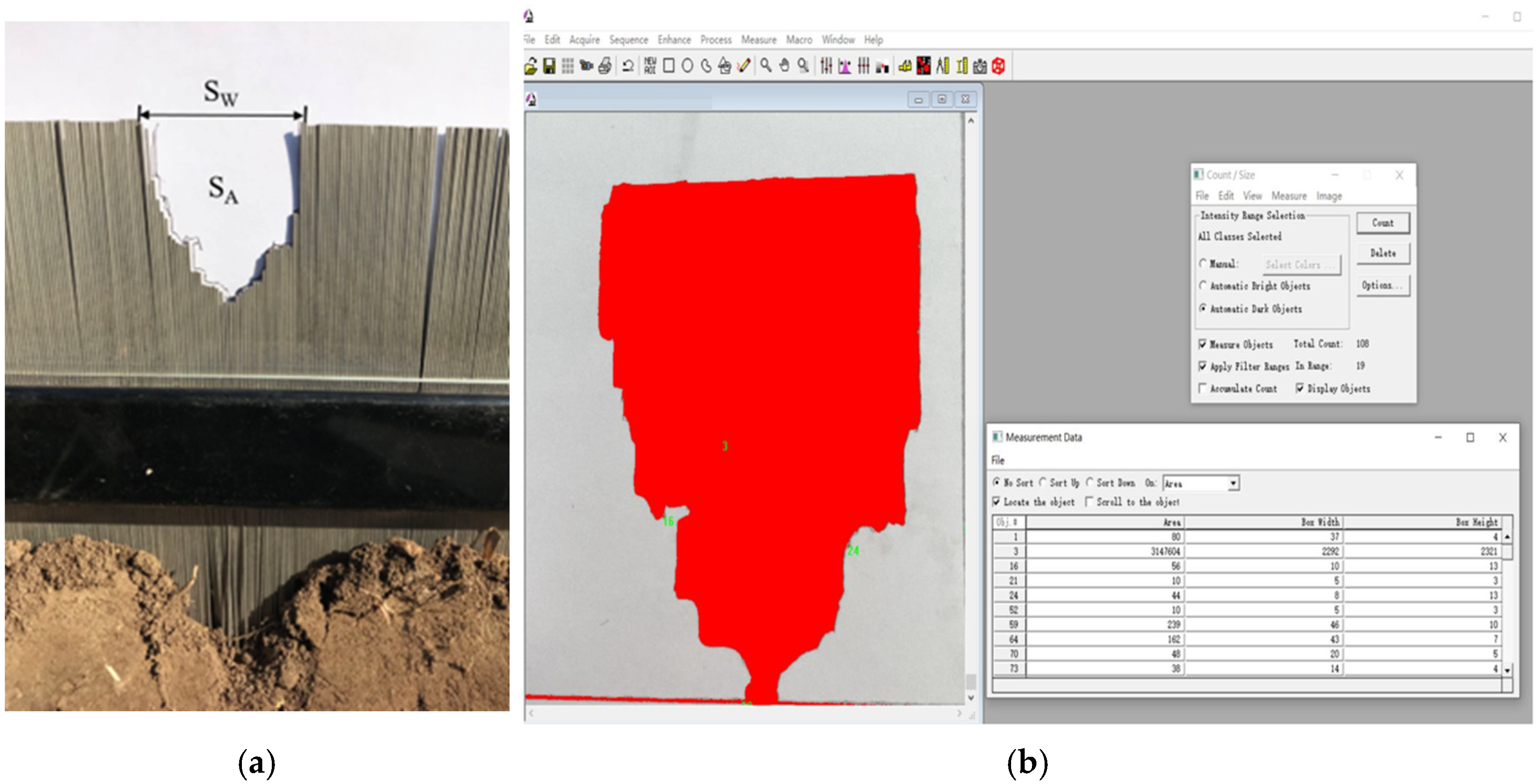
A custom contour profiler was used to capture the furrow profile created by the disc coulter, as shown in Figure 11a. Before measurement, the loose soil within the furrow was removed. The contour profiler was vertically placed in the furrow, allowing the slideable profilograph stylus to be freely released until its lower end touched the surface of the furrow, at which point the contour formed by the profilograph stylus represented the furrow profile. The contour was then drawn onto engineering paper, scanned to obtain a digital image, and analyzed using Image-Pro-Plus 6.0 image analysis software (Media Cybernetics Inc., Rockville, MD, USA). This process allowed the calculation of soil disturbance width (SW) and soil disturbance area (SA), as demonstrated in Figure 11b. Both SW and SA were measured relative to the original soil surface. Each furrow was measured at three random points, and the average value was used.
Figure 11.
Furrow cross-section profile testing: (a) contour profiler; (b) furrow profile data processing.
4. Results
4.1. Optimization Experiment of Toothed Disc Coulter Structural Parameters
According to the experimental design of the three-factor, five-level, second-order regression orthogonal rotation center combination, a total of 23 sets of toothed disc coulters with different structural parameter combinations were required for the experiment. Each parameter combination of toothed disc coulter models was imported into the EDEM and RecurDyn software for coupled simulation—the results are shown in Table 5.
Table 5.
Results of coupled simulation.
The variance analysis of the experimental results was carried out using the Design Expert 8.0.6 software—the results are presented in Table 6.
Table 6.
Variance analysis of performance evaluation indicators.
To explore the optimal parameter combination of the test factors and ensure that the best design conditions are within a reasonable range of the design parameters, the goal is to minimize draft and penetration resistance. The constraints are the level intervals of each factor. Design-Expert 8.0.6.1 software was used for multi-objective optimization of parameter combinations. The objective function and constraint conditions are shown in Equation (11). Considering that the number of serrations on the disc coulter was an integer, the optimization results show that when the angle of front serration is 16°, the angle of rear serration is 39.1°, and the number of serrations is 13, the draft is 185.8 N and the penetration resistance is 345.6 N.
4.2. Comparison Test Results of Draft and Penetration Resistance of Disc Plow Performance
Comparisons were made on the working resistance, soil disturbance width, and soil disturbance area of seven different disc coulters to determine which disc coulter had an advantage under different working requirements.
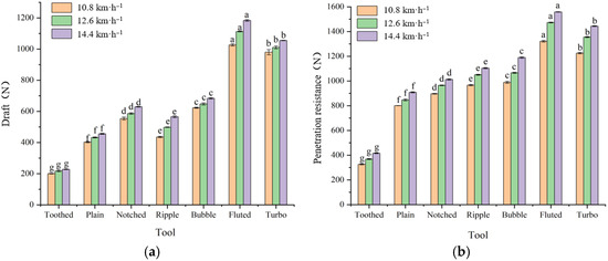
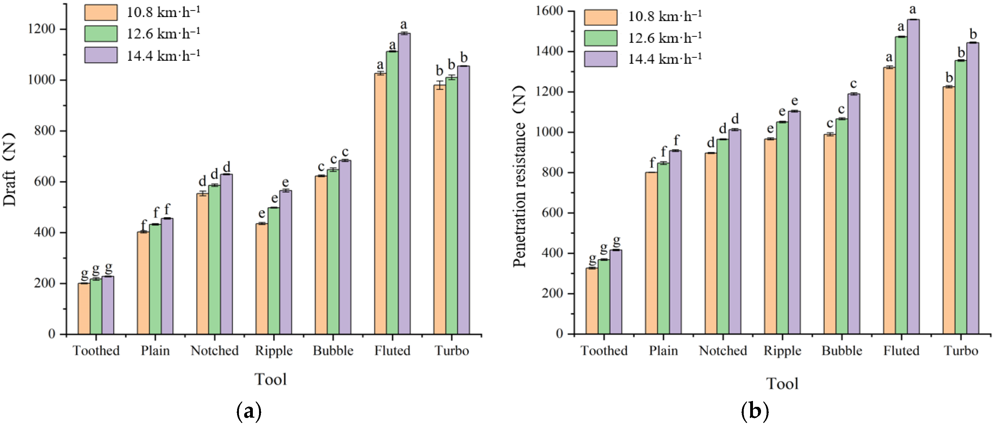
The operating speed significantly affects the draft (p < 0.05). As shown in Figure 12a, the draft increases with the increase in operating speed. Under the conditions of 12.6 km·h−1 and 14.4 km·h−1, the average draft increased by 6.6% and 13.6% compared to 10.8 km·h−1, respectively. As shown in Figure 12b, the operating speed significantly impacts the penetration resistance (p < 0.05), as the penetration resistance increases with the increase in operating speed. Under conditions 12.6 km·h−1 and 14.4 km·h−1, the average draft increased by 9.2% and 17.0% compared to 10.8 km·h−1, respectively. These conclusions are similar to those obtained by Bai and Zeng [37,38]. Plain disc coulters or coulters with a nearly flat surface were affected by operating speed, and coulters with fewer ripples were more affected by speed—a conclusion which is also reported by Wang et al. [39].
Figure 12.
Influence of various factors on: (a) draft and (b) penetration resistance. Note: According to the LSD multiple gap test (p < 0.05), means with different lowercase letters at the end have significant differences; error lines are standard deviations.
The type of disc coulter significantly influences draft (p < 0.05). The draft of plain disc coulters is less than that of all rippled disc coulters. This phenomenon occurs because, under identical diameter and amplitude parameters, a smaller number of corrugations produces individually sharper and more protruding crests. During the penetration and soil compression of the ripple disc coulter, the dominant soil deformation mechanism transitions from bending and tearing to compression and shearing. Fewer corrugations correspond to deeper and wider troughs. As each crest rotates out of the soil, substantial cavities emerge at the trough areas, which are subsequently intensely backfilled by surrounding soil mass. The following crest is then required to re-extrude the refilled soil. This cyclic process of soil extrusion, cavity formation and secondary extrusion induces extra energy dissipation and elevated draft. Conversely, disc coulters with abundant corrugations possess shallower troughs, which reduce soil backfilling volume and achieve continuous soil disturbance, thereby effectively mitigating draft force demand. Draft gradually increases with the decrease in the number of ripples in the rippled disc. Under the condition of 14.4 km·h−1, the bubble disc coulter, turbo disc coulter, fluted disc coulter are 21.0%, 86.6%, and 109.5% higher than the ripple disc coulter, respectively. The draft of individual disc coulters under three operating speed conditions varies from 200.4 to 1183.9 N, with the fluted disc coulter experiencing the greatest draft and the toothed disc coulter experiencing the least. Under the condition of 14.4 km·h−1, the toothed disc coulter’s draft is 80.8% less than that of the notched disc coulter. The penetration resistance of a single disc coulter under three operating speed conditions ranges from 326.6 to 1558.0 N, with the fluted disc coulter experiencing the greatest penetration resistance and the toothed disc coulter experiencing the least. Under the condition of 14.4 km·h−1, the toothed disc coulter’s penetration resistance is 73.3% less than that of the notched disc coulter.
A plain disc coulter acts like a blunt circular cutter. It squeezes the entire soil to both sides and forms a high-compression zone, where the soil mainly undergoes compressive failure and large-volume displacement, requiring sustained high horizontal draft force and vertical downforce to ensure soil penetration. Although a ripple disc coulter has crests and troughs, it still retains a continuous blunt edge. During rolling, the crests squeeze the soil forcefully like large wedges, and the soil in trough areas is also pushed and compressed. Its soil disturbance behavior is still dominated by compressive deformation, with only a slight improvement compared with the plain disc coulter due to the local shear effect of wave crests. A toothed disc coulter is equipped with discontinuous sharp cutting edges along the edge. Each tooth functions as an acute-angle cutting structure. In operation, the tooth tip penetrates the soil first with extremely high contact pressure. Under the same vertical load, the stress on the tooth tip is much higher than that of continuous edges, so it can easily pierce hard soil and straw layers with lower downforce demand and smaller penetration resistance, which reduces the lifting force requirement of the implement and weakens the horizontal friction component caused by the vertical load. The cutting teeth further apply tensile and shear action to the soil. Following the sliding cutting principle, the soil is torn along bilateral shear surfaces instead of undergoing overall compression and displacement, and the horizontal draft force required for shear failure is far lower than that for compression failure. When a toothed disc coulter works at high speed, each tooth cuts the soil like a high-speed blade; the soil is rapidly split and discharged through tooth gaps, resulting in a small disturbed soil volume and stable operating resistance.
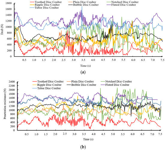
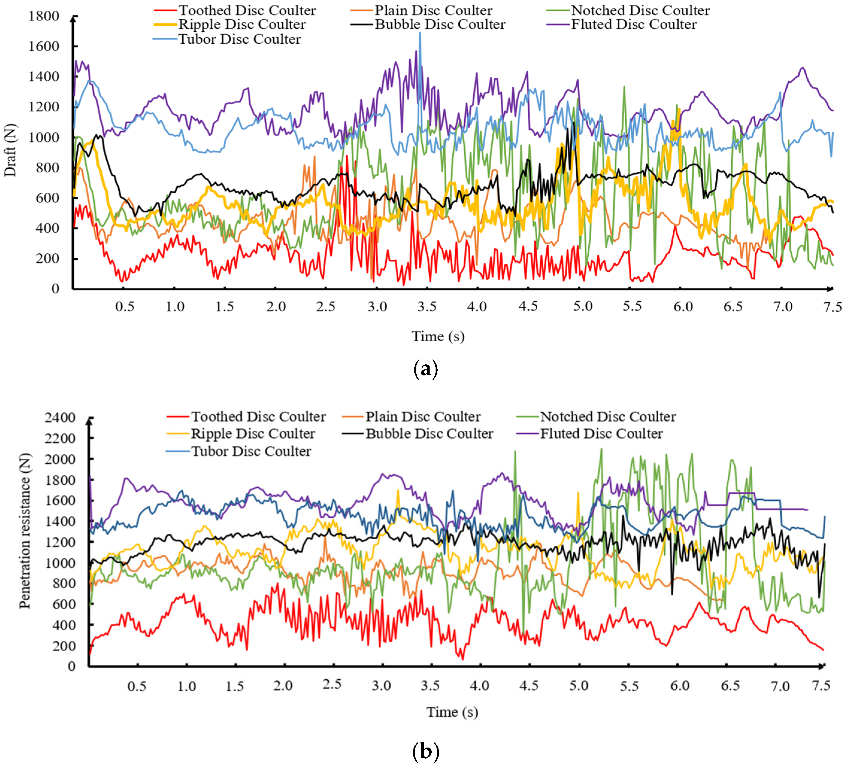
The draft and penetration forces exerted during the operation of the seven types of disc coulters at speed 14.4 km·h−1 are illustrated in Figure 13.
Figure 13.
Forces experienced by seven types of disc coulters during operation: (a) draft force; (b) penetration force.
The field performance indices of the toothed disc coulter with optimal structural parameters under the 14.4 km·h−1 working condition were measured as follows: the draft was 227.5 ± 8.9 N, and the penetration resistance was 415.9 ± 5.3 N. The main factors accounting for the discrepancies are summarized in the following four aspects: (1) simplification of the soil constitutive model and uncertainty of actual soil media. The simulation assumes soil to be a homogeneous, isotropic and continuous medium and ignores soil adhesion. In practical tillage layers, the strength of soil and moisture content present a nonlinear distribution at different soil depths. The single fixed parameters adopted in the simulation (such as constant moisture content) cannot reflect the random distribution of local dry soil layers and wet soil clods. Extra impact loads are generated during soil cutting by the coulter, thereby producing obvious differences between measured resistance and simulated values. (2) In the simulation, soil particle fracture follows predefined failure criteria, while natural soil contains inherent cracks, root networks and undecomposed straw residues. During the cutting process of the toothed disc coulter, the heterogeneous substances induce unexpected stress concentration, which further increases the measured penetration resistance. (3) The simulation adopts ideal uniform linear motion and rigid boundary constraints. In field conditions, however, the tractor–implement–soil system forms a complex vibration coupling system. Uneven ground surfaces and variable soil strength cause fluctuations in tractor traveling speed. Meanwhile, the hydraulic suspension system produces floating profiling movement due to uneven soil strength, which changes the actual penetration angle of the toothed disc coulter and generates additional dynamic resistance. Such dynamic characteristics cannot be fully reflected in the simulation, resulting in fluctuations in field test indices. (4) The coulter surface is set as an ideal smooth or uniformly worn state in the simulation. In high-speed field operation, however, the cutting edge of the toothed disc coulter undergoes a self-sharpening and running-in process at the initial test stage. Microscopic soil adhesion exists on the tool surface during field tests, which increases the sliding friction coefficient. By contrast, the simulation parameters are generally configured based on pure sliding friction and neglect soil adhesive characteristics, which eventually makes the measured penetration resistance significantly higher than the simulated results.
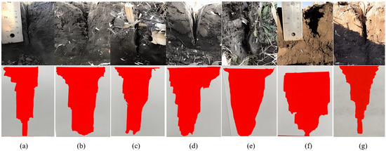
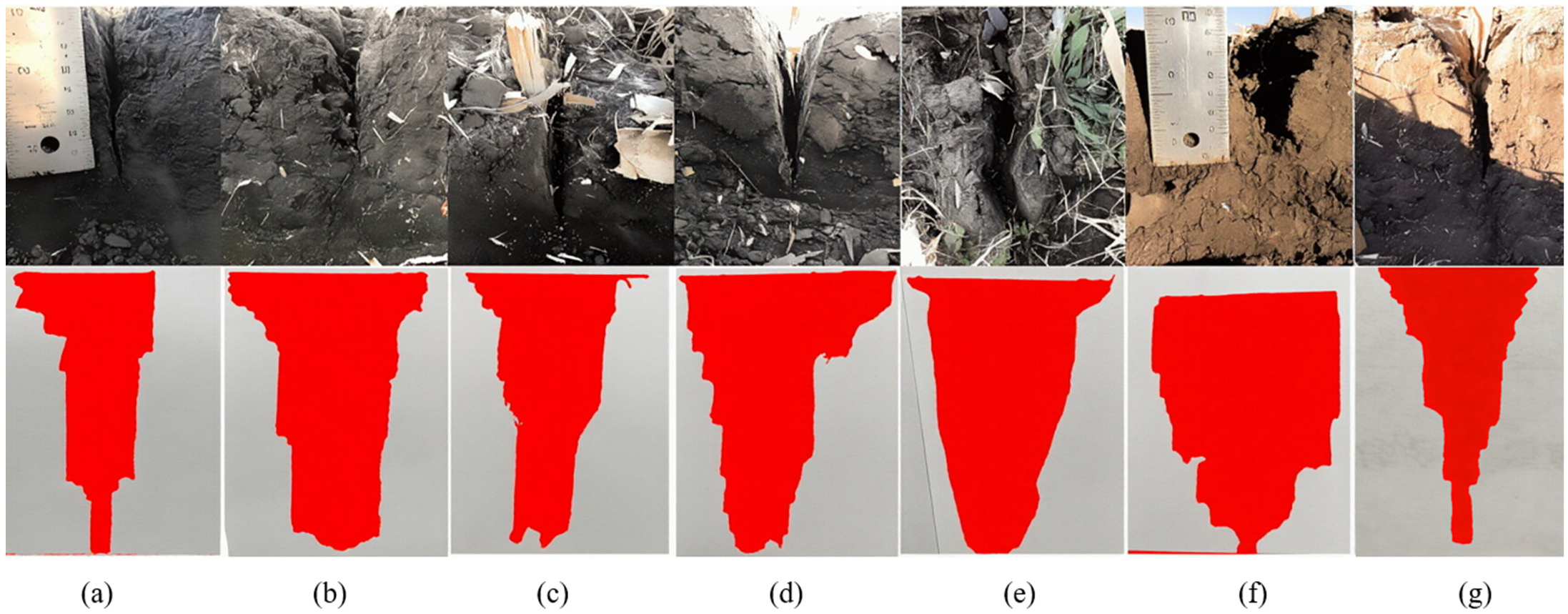
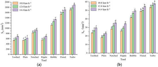
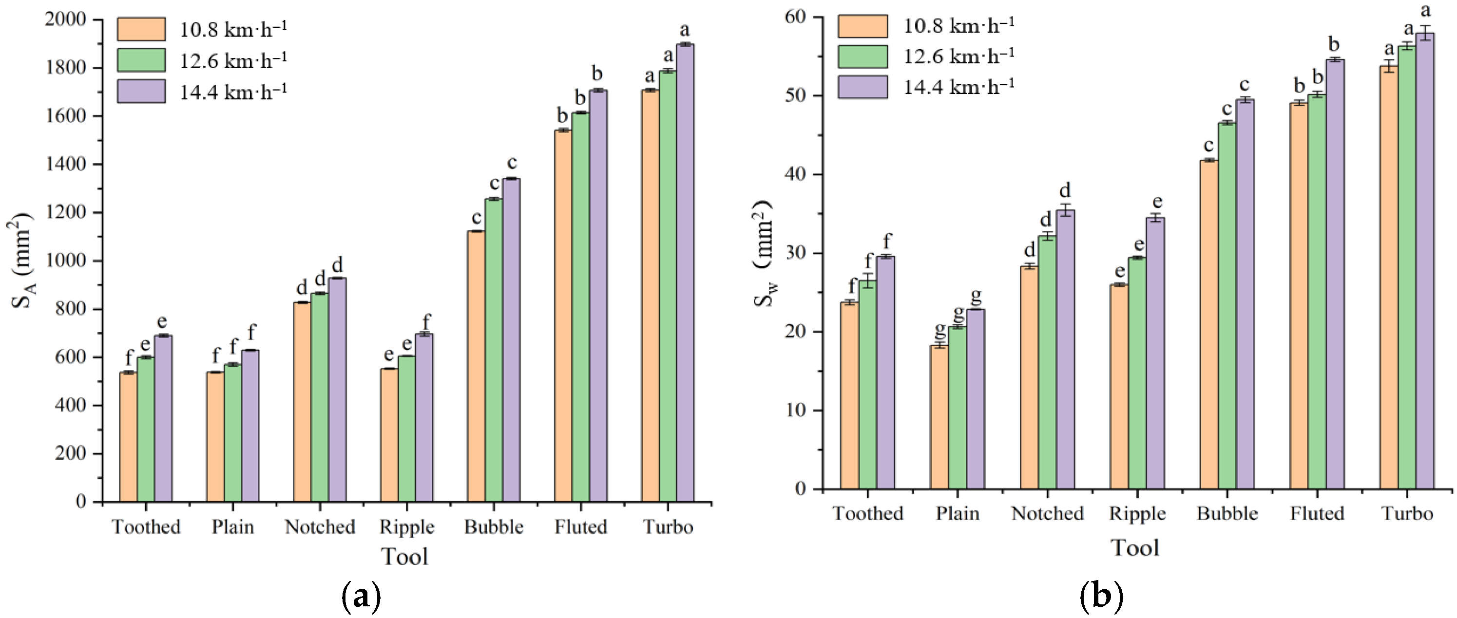
The cross-sectional contour of the furrows created by the disc coulter and the post-operation results are illustrated in Figure 14. As shown in Figure 13, the operation speed significantly impacted the soil disturbance width and soil disturbance area (p < 0.05). Higher working speeds resulted in larger soil disturbance widths and areas. Under the conditions of 12.6 km·h−1 and 14.4 km·h−1, the soil disturbance width increased by 8.7% and 18.0% respectively compared to the condition of 10.8 km·h−1, while the soil disturbance area grew by 6.9% and 14.5%. Zeng [40] arrived at the same conclusion under high-speed operating conditions of the coulter.
Figure 14.
Cross-sectional contour diagrams and data processing of furrow created by seven types of disc coulters: (a) plain disc coulter; (b) notched disc coulter; (c) ripple disc coulter; (d) bubble disc coulter; (e) fluted disc coulter; (f) turbo disc coulter; and (g) toothed disc coulter.
As can be inferred from Figure 15, the type of disc coulter significantly impacts the soil disturbance width and area (p < 0.05). The plain disc coulter result in the smallest soil disturbance width and area, which was consistent with the research findings of Francetto [41]. Conversely, the turbo disc coulter results in the maximum soil disturbance width and area, while the toothed disc coulter exhibits a slightly higher soil disturbance width and area than the plain disc coulter. Plain disc coulters yield a smaller soil disturbance width and area than their fluted counterparts. Among fluted disc coulters, the disturbance width and area appear to be related to the number of flutes. Under the condition of 14.4 km·h−1, the soil disturbance areas of the ripple disc coulter, bubble disc coulter, and fluted disc coulter are respectively 10.1%, 29.3%, and 63.3% less than that of the turbo disc coulter. Their soil disturbance widths are reduced by 5.9%, 14.7%, and 40.5% respectively, which corroborates the findings of McKyes [42]. Different working widths resulted in variations in soil disturbance width, with narrower disc coulters typically resulting in smaller disturbance widths. However, our experiment showed that the notched disc coulter, which has a greater working width than the ripple disc coulter, produced a smaller soil disturbance width. This discrepancy could potentially be attributed to the 10 mm plain edge on the ripple disc coulter, which reduces the soil disturbance width during operation, a finding that contrasts with Zeng’s conclusion [38]. The study also observed variations in soil disturbance areas with equal disturbance widths or vice versa among different types of disc coulters. This discrepancy could possibly be related to the shape of the furrow profile created by each disc coulter.
Figure 15.
Impact of various factors on: (a) soil disturbance area and (b) soil disturbance width. Note: According to the LSD multiple range test (p < 0.05), the means behind different lowercase letters have significant differences; error bars represent standard deviations.
5. Discussion
5.1. Influence of Experimental Factors on Draft
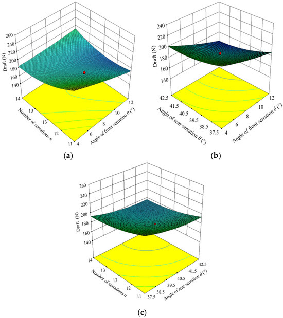
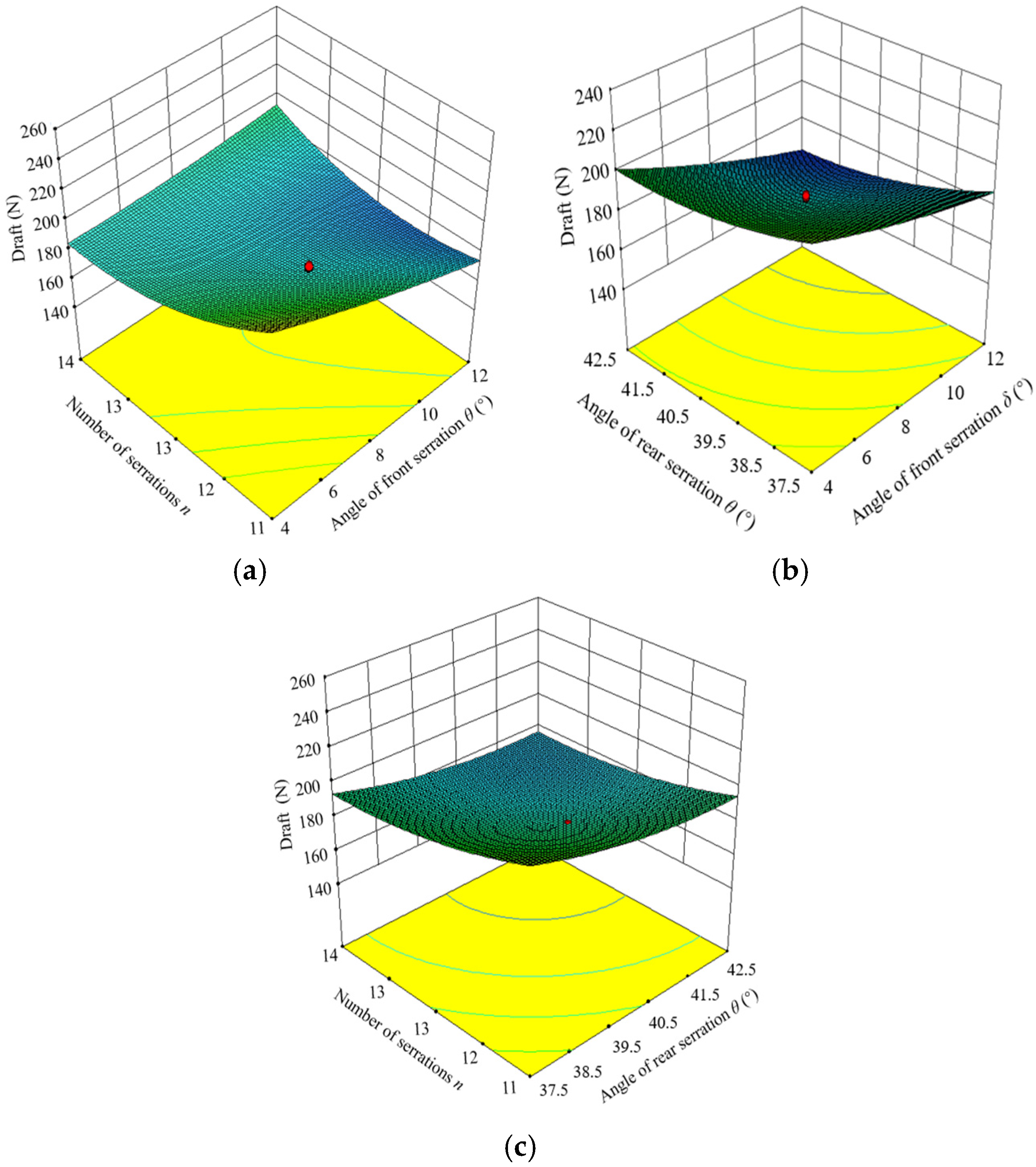
As can be seen from the variance analysis in Table 6, the angle of front serration, the angle of rear serration, and the number of serrations all have extremely significant effects on draft. The interaction between the angle of front serration and the number of serrations has an extremely significant effect on draft. The order of influence from large to small is as follows: the angle of front serration, the number of serrations, the angle of rear serration, and the interaction between the angle of front serration and the number of serrations. The regression equation of draft is obtained through Design Expert 8.0.6, and its R2 value is 0.95. As shown in Table 6, the model is extremely significant at a confidence level of p < 0.01, and the lack of fit is not significant, indicating that the regression analysis is valid. By eliminating insignificant factors, the regression equation between various factors and draft is obtained as shown in Equation (12). The laws of the effects of various experimental factors on draft can be analyzed through the response surface, as shown in Figure 16. When the posterior tooth angle is at the design center point (40°), the influence rule of the angle of front serration and the number of serrations on the draft is as shown in Figure 16a. When the number of serrations is small, as the angle of front serration increases, the draft decreases because as the angle of front serration increases; the toothed disc coulter’s ability to enter the soil increases, making it easier for the coulter teeth to enter the soil, which leads to a decrease in draft [43]. When the angle of front serration is certain, as the number of serrations increases, the draft shows a trend of first decreasing and then increasing. A smaller number of serrations reduces the contact area between the toothed disc and soil, thereby facilitating soil penetration and lowering draft resistance. When the number of serrations is large, more serrations engage with the soil at a given moment. This demands greater penetration force to drive the toothed disc into the soil and consequently increases draft resistance. This increase in draft force is not the draft of the toothed disc, but the increase in the rolling resistance of the disc [44]. When the number of serrations is at the design center point (12), the influence of the angle of front serration and the angle of rear serration on draft is as shown in Figure 16b. As the angle of rear serration increases, the draft decreases. As the rear serration angle rises, the rear cutting edge produces an enhanced sliding shear action on the soil, which improves the soil cutting performance of the toothed disc coulter and lowers draft resistance [45]. When the angle of front serration is at the design center point (8°), the influence of the number of serrations and the angle of rear serration on the draft is as shown in Figure 16c.
Figure 16.
Impact of the toothed disc coulter structural parameters on the draft: (a) the angle of front serration and number of serrations; (b) the angle of front serration and angle of rear serration; and (c) the number of serrations and angle of rear serration.
5.2. Impact of Test Factors on Penetration Resistance
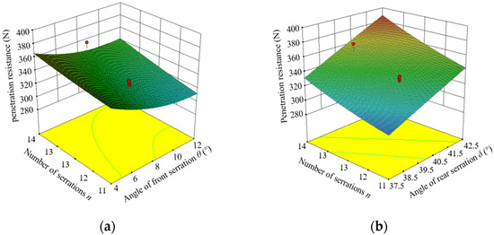
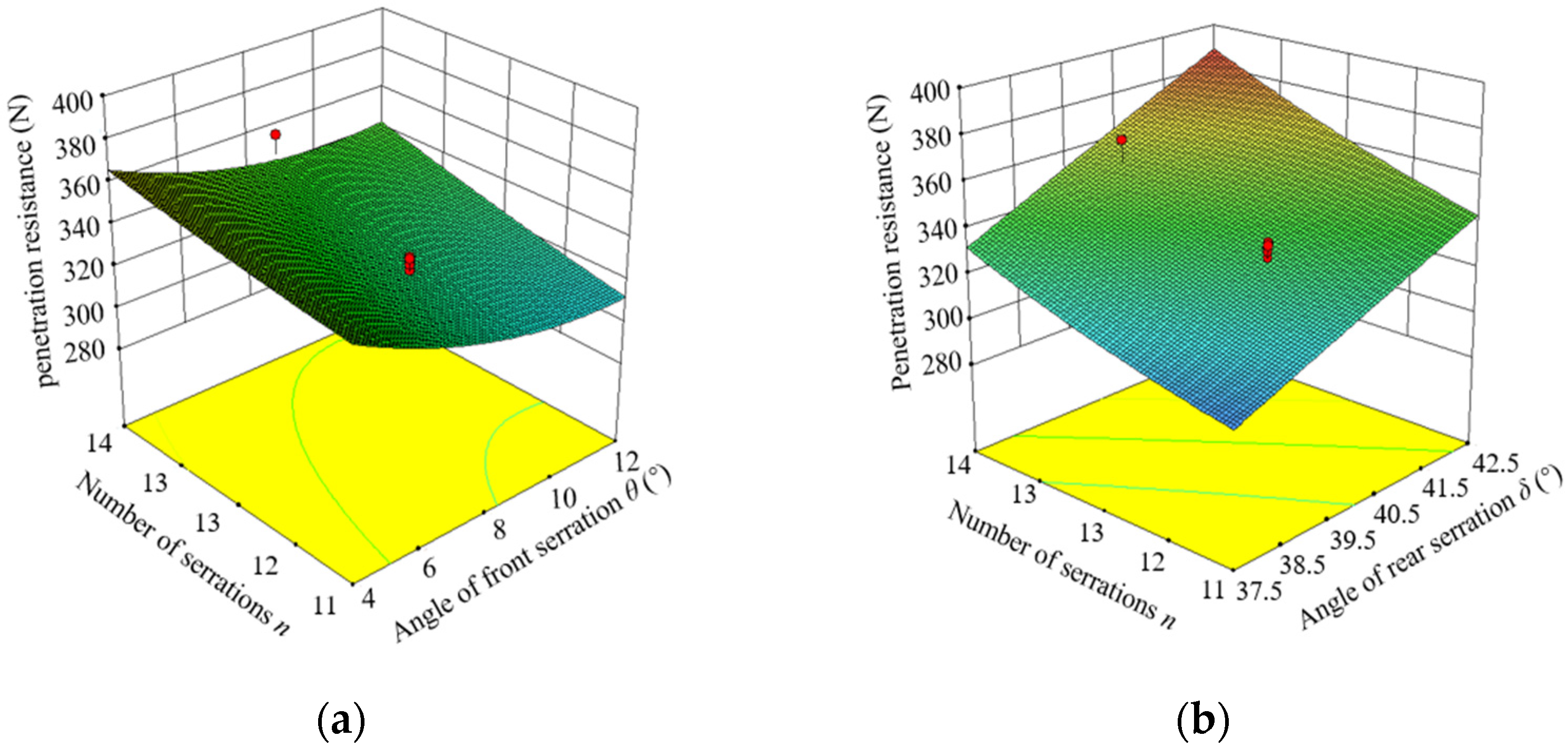
The variance analysis in Table 6 shows that each test factor has a significant impact on penetration resistance, while interactions between factors and other sources of variation do not significantly affect penetration resistance. The order of impact, from high to low, is the angle of front serration, the number of serrations, and the angle of rear serration. The regression equation for penetration resistance was obtained through Design Expert 8.0.6 software, and its R2 value is 0.89. Table 5 shows that the model is significant at p < 0.01, and the lack of fit is not significant, indicating that the regression analysis is valid. The regression equations of each factor and draft, after excluding insignificant factors, are shown in Equation (13). The rules of how test factors affect penetration resistance can be analyzed through the response surface, as shown in Figure 17. When the posterior tooth angle is at the design center point (40°), the impact rules of the angle of front serration and the number of serrations on penetration resistance are as shown in Figure 17a. As the angle of front serration increases, penetration resistance decreases because an increase in the angle of front serration makes it easier for the toothed disc coulter to penetrate the soil, reducing penetration resistance [46]. When the angle of front serration is constant, penetration resistance increases with an increase in the number of serrations. This is because when the number of serrations increases, the number of serrations that penetrate the soil at the same time also increases, requiring greater penetration force to force the toothed disc into the soil [10]. When the angle of front serration is at the design center point (8°), the rules of how the angle of rear serration and number of serrations affect penetration resistance are as shown in Figure 17b. As the angle of rear serration increases, penetration resistance increases because an increase in the angle of rear serration leads to an increase in the width of the coulter teeth, requiring more penetration resistance to achieve the required depth of penetration.
Figure 17.
Impact of toothed disc coulter structural parameters on penetration resistance: (a) the angle of front serration and number of serrations; (b) the number of serrations and angle of rear serration.
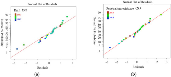
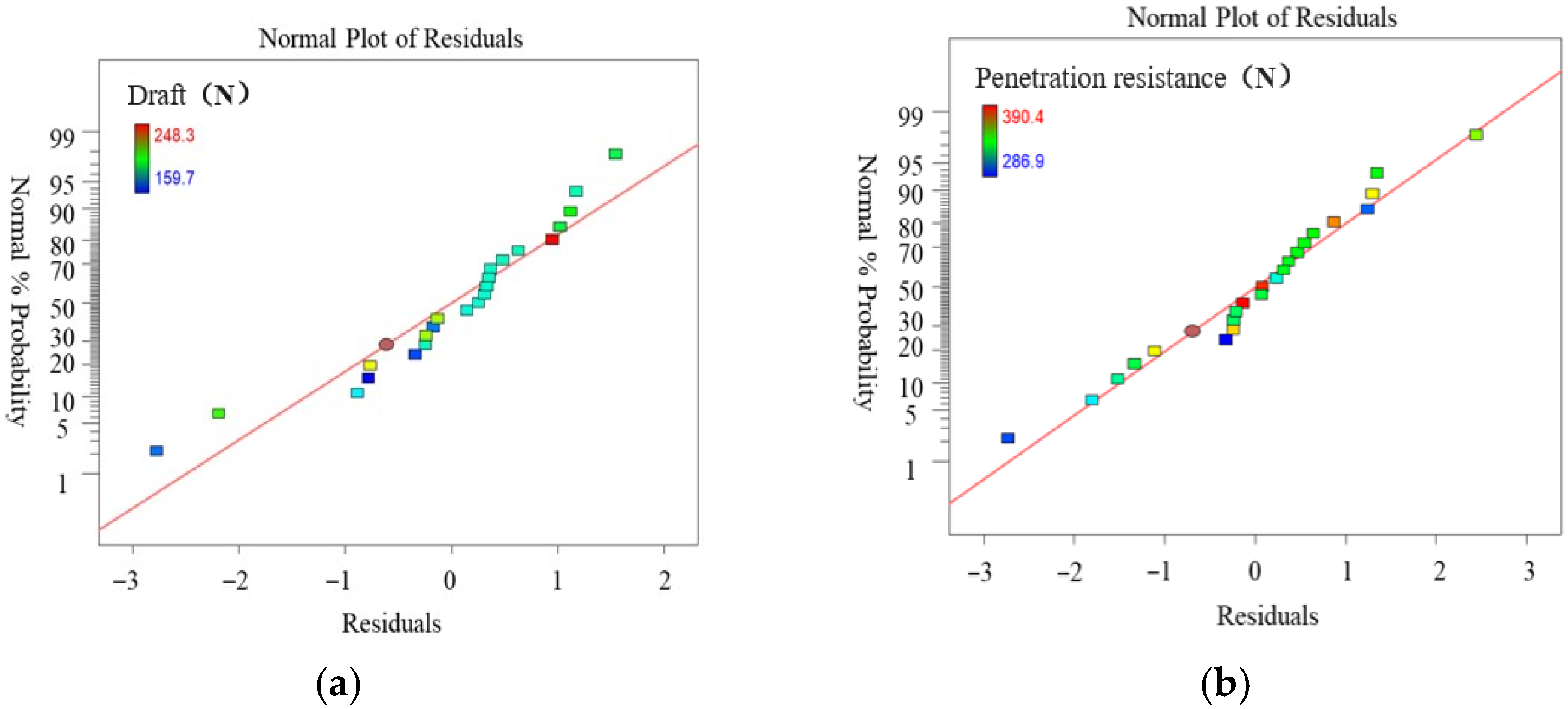
On the basis of variance analysis, residual analysis was performed for the draft and penetration resistance models. As shown in Figure 18, the residuals of both models follow a normal distribution, indicating that the models established between draft and penetration resistance and the experimental factors are reliable and reasonable. These models can be used for subsequent optimization of parameter combinations and predictive analysis of evaluation indicators.
Figure 18.
Normal plots of residuals for: (a) draft and (b) penetration resistance.
5.3. Comparative Test Results of Disc Coulter Performance
Significant differences exist among the seven types of disc coulters in terms of performance indicators, highlighting the feasibility of selecting different disc coulters to achieve diverse tillage objectives.
The working resistance of a coulter reflects the ease with which it penetrates the soil, as well as the minimum load required for it to function effectively at a given operational depth. The load placed on a coulter directly influences its performance; if the load is too light, the coulter cannot penetrate the soil, while an excessive load leads to an overconsumption of energy and resources. Draft increases with the speed of operation, as an increase in speed results in a larger amount of soil coming into contact with the coulter per unit time, thereby amplifying friction and throwing forces, and subsequently increasing the working resistance. Disc coulters with ripples have a larger contact length and area with the soil, leading to greater soil disturbance and therefore an increased interaction force between the coulter and the soil. Similar conclusions have been reached in studies by Darmora & Pandey and Hasimu & Chen [47,48]. Penetration resistance represents the downward force needed to maintain a specific soil penetration depth for a disc coulter. Disc coulters with higher draft also have higher penetration resistance, as confirmed by previous research. The penetration force required to maintain a specific penetration depth is directly proportional to the diameter of the coulter; hence, larger disc coulters require more substantial penetration forces to penetrate the soil. An increased diameter necessitates greater penetration forces and as a result, additional weight to the machine, which in turn leads to increased draft and energy consumption. The geometry of the edge of the disc coulter can alter this ratio, with toothed disc coulters requiring less penetration force than other coulters. This can be primarily attributed to the toothed design of these coulters, as the smaller contact area with the soil at their toothed edges makes them easier to penetrate and maintain a specific soil depth.
The profile of the furrow reflects the area and cross-sectional shape of the soil disturbed by the coulter. Greater soil disturbance width is conducive to smooth seeding operations; however, excessive soil disturbance can accelerate the loss of soil moisture, impede sufficient seed–soil contact, and decrease germination rates while delaying the timing of germination, ultimately affecting crop yield. During operation, ripple disc coulters swing side-to-side in the soil, aiding in soil fragmentation. It is necessary to choose the appropriate coulter type based on various tillage requirements, such as tillage objectives and planting patterns.
In agricultural production, reducing draft to decrease energy consumption is crucial, along with minimizing penetration resistance while ensuring proper soil penetration depth to achieve lighter seeding equipment. Excessive soil disturbance can lead to increased resistance, and the ratio of soil disturbance area to draft (SA/FV) is defined as soil loosening efficiency by McKyes [42]. Among the seven types of disc coulters, the toothed disc coulter exhibits the best performance in terms of soil loosening efficiency.
Through a combination of simulation and field experiments, the structure of the toothed disc coulter was optimized. It was found that the toothed disc coulter exhibits excellent resistance reduction performance under high-speed operating conditions; however, due to its own structural characteristics, it has certain limitations in terms of wear resistance. In sandy or stony soil conditions, contact stress concentration may occur, thereby accelerating abrasive wear and shortening the service life of the disc coulter. Under high-speed operation, the disc coulter is subjected to cyclic impact loads, and the optimized structure may carry the risk of fatigue crack propagation. Future work should focus on addressing these deficiencies from the following aspects: (1) conduct abrasive wear research based on accelerated wear bench tests to establish a quantitative relationship between geometric parameters and wear rate; (2) perform fatigue life simulation using the finite element method to evaluate the reliability of the structure under cyclic loading; and (3) carry out long-term field tracking tests to compare the actual service life (in mu per operation or hectare per operation) of the disc coulter before and after optimization. Only by combining the resistance reduction design with high-durability materials (such as wear-resistant coatings or cemented carbide) can this optimized solution truly possess engineering practical value.
6. Conclusions
This study used a bidirectional coupling technique based on DEM-MBD, along with a quadratic regression orthogonal rotating central combination test method, to construct a virtual simulation model of a toothed disc coulter’s interaction with the soil. This was achieved using EDEM and RecurDyn software. The optimal structural parameters for a toothed disc coulter were identified and these parameters were validated through field experiments. A comparative experimental study was conducted between the toothed disc coulter and six other active disc coulters, leading to the following conclusions:
(1) Parameter optimization results suggested that at a working speed of 14.4 km·h−1 and a soil penetration depth of 50 mm, the minimum values of draft and penetration resistance were achieved when the angle of front serration, angle of rear serration, and number of serrations were 16°, 39.1°and 13, respectively.
(2) Field performance evaluation indicators for the optimally structured toothed disc coulter at a working speed of 14.4 km·h−1 and a soil penetration depth of 50 mm revealed a draft of 227.5 ± 8.9 N and penetration resistance of 415.9 ± 5.3 N.
(3) The type of disc coulter and working speed significantly influenced both draft and penetration resistance. As the working speed increased, both the draft and penetration resistance of the disc coulter increased. The draft of the plain disc coulter was less than all the ripple disc coulters, and within the ripple disc coulters, the draft gradually increased as the number of ridges decreases. The fluted disc coulter experienced the greatest penetration resistance, while the toothed disc coulter experienced the least.
(4) The soil disturbance width and area of the plain disc coulter were less than those of the ripple disc coulters. Within the ripple disc coulters, the soil disturbance width and area were related to the number of ridges. Among the seven types of disc coulters, the toothed disc coulter demonstrated the best soil loosening efficiency.
Author Contributions
Conceptualization, X.W. and S.H.; methodology, S.H. and H.C.; software, X.L., H.Y. and C.X.; validation, S.L. and S.H.; writing—original draft preparation, X.W.; writing—review and editing, X.W. and S.H.; project administration, H.C. All authors have read and agreed to the published version of the manuscript.
Funding
This research was supported by the National Key R&D Program of China (2021YFD20000401).
Data Availability Statement
The datasets used and/or analyzed during the current study are available from the corresponding author upon request.
Acknowledgments
We would like to express our gratitude to the Heilongjiang Provincial Engineering Research Center for Mechanization and Materialization of Major Crop Production for providing support during the experimental process.
Conflicts of Interest
The authors declare that they have no known competing financial interests or personal relationships that could have appeared to influence the work reported in this paper.
References
- Zhai, L. Study on The Effects of Plough’s Working and Structure Parameters on Its Resistance under Rheological Soil Conditions. Doctoral Dissertation, Nanjing Agricultural University, Nanjing, China, 2011. [Google Scholar]
- Barzegar, M.; Hashemi, S.J.; Nazokdast, H.; Karimi, R. Evaluating the draft force and soil-tool adhesion of a UHMW-PE coated furrower. Soil Tillage Res. 2016, 163, 160–167. [Google Scholar] [CrossRef] [Scilit]
- Li, Q.; Guo, J.; Hu, J.; Zhang, W.; Wang, H.; Dai, H. Research Status of Wear Resistance and Drag Reduction Treatment of Soil Cultivation Components. Surf. Technol. 2016, 46, 119–126. [Google Scholar]
- Sun, G.; Chen, F.; Xiao, X. Preliminary Study on Effects of Rotational Tillage on Soil Physical Properties and Rice Yield. Trans. Chin. Soc. Agric. Eng. 2007, 12, 109–113. [Google Scholar]
- Ren, Q. Advances in Ground Machine Desorption and Drag Reduction Bionics Research; Science in China Press: Beijing, China, 2008; Volume 38, pp. 1353–1364. [Google Scholar]
- Zhang, J.; Tong, J.; Ma, Y. Design and Experiment of Bionic Anti-drag Subsoiler. Trans. Chin. Soc. Agric. Mach. 2014, 45, 141–145. [Google Scholar]
- Wu, L.; Jiao, Z.; Song, Y.; Xin, M.; Liu, C.; Kong, A.; Cui, H.; Qi, S.; Liu, F.; Ren, W. Design and Experiment on Testing System for Operation Resistance of Soil Engaging Parts. J. Shenyang Agric. Univ. 2016, 47, 589–596. [Google Scholar]
- Tabatabaeefar, A.; Emamzadeh, H.; Varnamkhasti, M.G.; Rahimizadeh, R.; Karimi, M. Comparison of energy of tillage systems in wheat production. Energy 2009, 34, 41–45. [Google Scholar] [CrossRef] [Scilit]
- Kogut, Z.; Sergiel, L.; Żurek, G. The effect of the disc setup angles and working depth on disc harrow working resistance. Biosyst. Eng. 2016, 151, 328–337. [Google Scholar] [CrossRef] [Scilit]
- Magalhães, P.S.G.; Bianchini, A.; Braunbeck, O.A. Simulated and Experimental Analyses of a Toothed Rolling Coulter for Cutting Crop Residues. Biosyst. Eng. 2007, 96, 193–200. [Google Scholar] [CrossRef] [Scilit]
- Nejadi, J.; Raoufat, M.H. Residue management practices and planter attachments for corn production in a conservation agriculture system. Span. J. Agric. Res. 2013, 11, 919–928. [Google Scholar] [CrossRef] [Scilit]
- Bianchini, A.; Magalhães, P.S.G. Evaluation of coulters for cutting sugar cane residue in a soil bin. Biosyst. Eng. 2008, 100, 370–375. [Google Scholar] [CrossRef] [Scilit]
- Tagar, A.A.; Changying, J.; Adamowski, J.; Malard, J.; Qi, C.S.; Qishuo, D.; Abbasi, N.A. Finite element simulation of soil failure patterns under soil bin and field testing conditions. Soil Tillage Res. 2015, 145, 157–170. [Google Scholar] [CrossRef] [Scilit]
- Xie, B.; Luo, Z.; Song, Z.; Wen, C.; Zhang, S.; Mao, E. Review of off-road vehicle tire-soil interaction modeling methods and experimental techniques. Trans. Chin. Soc. Agric. Eng. 2022, 38, 51–63. [Google Scholar]
- Karmakar, S.; Kushwaha, R.L. Dynamic modeling of soil-tool interaction: An overview from a fluid flow perspective. J. Terramech. 2006, 43, 411–425. [Google Scholar] [CrossRef] [Scilit]
- Zhu, L.; Ge, J.R.; Cheng, X.; Peng, S.S.; Qi, Y.Y.; Zhang, S.W.; Zhu, D.Q. Modeling of share/soil interaction of a horizontally reversible plow using computational fluid dynamics. J. Terramech. 2017, 72, 1–8. [Google Scholar] [CrossRef] [Scilit]
- Ma, Y.; Wang, A.; Zhao, J.; Hao, J.; Li, J.; Ma, L.; Zhao, W.; Wu, Y. Simulation Analysis and Experiment of Drag Reduction Effect of Convex Blade Subsoiler Based on Discrete Element Method. Trans. Chin. Soc. Agric. Eng. (Trans. CSAE) 2019, 35, 16–23. [Google Scholar]
- Liu, J.; Chen, Y.; Kushwaha, R.L. Effect of tillage speed and straw length on soil and straw movement by a sweep. Soil Tillage Res. 2010, 109, 9–17. [Google Scholar] [CrossRef] [Scilit]
- Zhang, S.; Jia, X.; Dong, J. Optimization of operating angles of disc coulters for maize residue management using discrete element method. Comput. Electron. Agric. 2024, 218, 108691. [Google Scholar] [CrossRef] [Scilit]
- Liu, X.; Guo, Z.; Tong, Z.; He, M.; Gao, P.; Ma, Y.; Xu, Z.A. Study on the interaction mechanism between disc coulters and maize root-soil composites based on DEM-MBD coupling simulation. Agriculture 2026, 16, 270. [Google Scholar] [CrossRef] [Scilit]
- McKyes, E. Soil Cutting and Tillage, 1st ed.; Elsevier Science: Amsterdam, The Netherlands, 1985; pp. 38–60. [Google Scholar]
- Wang, X.; Gao, P.; Yue, B.; Shen, H.; Fu, Z.; Zheng, Z.; Zhu, R.; Huang, Y. Optimisation of installation parameters of subsoiler’ wing using the discrete element method. Comput. Electron. Agric. 2019, 162, 523–530. [Google Scholar] [CrossRef] [Scilit]
- Hang, C.; Gao, X.; Yuan, M.; Huang, Y.; Zhu, R. Discrete element simulations and experiments of soil disturbance as affected by the tine spacing of subsoiler. Biosyst. Eng. 2018, 168, 73–82. [Google Scholar] [CrossRef] [Scilit]
- Tu, M.; Cao, T.; Wan, Z.; Mo, H.; Zhang, G. Calibration and Shear Experiments of the Discrete Element Bonding Parameters for Water Caltrop. J. Huazhong Agric. Univ. 2023, 42, 270–278. [Google Scholar] [CrossRef]
- Niu, Z.; Jiang, S.; Kong, X.; Geng, J.; Li, H.; Liu, J. Impact Breakage Characteristics and Discrete Element Simulation of Extruded Pellet Feed. Trans. Chin. Soc. Agric. Mach. 2023, 54, 371–380. Available online: https://kns.cnki.net/kcms2/detail/11.1964.S.20230529.1257.014.html (accessed on 30 May 2023).
- Mak, J.; Chen, Y.; Sadek, M.A. Determining parameters of a discrete element model for soil-tool interaction. Soil Tillage Res. 2012, 118, 117–122. [Google Scholar] [CrossRef] [Scilit]
- Huang, Y.; Hang, C.; Yuan, M.; Wang, B.; Zhu, R. Discrete Element Simulation and Experiment on Disturbance Behavior of Subsoiling. Trans. Chin. Soc. Agric. Mach. 2016, 47, 80–88. [Google Scholar]
- Cao, X.; Wang, Q.; Li, H.; He, J.; Lu, C. Combined Row Cleaners Research with Side Cutter and Stubble Clean Disk of Corn No-till Seeder. Trans. Chin. Soc. Agric. Mach. 2021, 52, 36–44. [Google Scholar]
- Wang, X.; Yue, B.; Gao, X.; Zheng, Z.; Zhu, R.; Huang, Y. Discrete Element Simulations and Experiments of Disturbance Behavior as Affected by Mounting Height of Subsoiler’s Wing. Trans. Chin. Soc. Agric. Mach. 2018, 49, 124–136. [Google Scholar]
- Wang, Y.; Xue, W.; Ma, Y.; Tong, J.; Liu, X.; Sun, J. DEM and soil bin study on a biomimetic disc furrow opener. Comput. Electron. Agric. 2019, 156, 209–216. [Google Scholar] [CrossRef] [Scilit]
- Chen, Y.; Munkholm, L.J.; Nyord, T. A discrete element model for soil–sweep interaction in three different soils. Soil Tillage Res. 2013, 126, 34–41. [Google Scholar] [CrossRef] [Scilit]
- Asaf, Z.; Rubinstein, D.; Shmulevich, I. Determination of discrete element model parameters required for soil tillage. Soil Tillage Res. 2007, 92, 227–242. [Google Scholar] [CrossRef] [Scilit]
- Ding, Q.; Ren, J.; Adam, B.E.; Zhao, J.; Ge, S.; Li, Y. DEM Analysis of Subsoiling Process in Wet Clayey Paddy Soil. Trans. Chin. Soc. Agric. Mach. 2017, 48, 38–48. [Google Scholar]
- Zheng, K.; He, J.; Li, H.; Diao, P.; Wang, Q.; Zhao, H. Research on Polyline Soil-breaking Blade Subsoiler Based on Subsoiling Soil Model Using Discrete Element Method. Trans. Chin. Soc. Agric. Mach. 2016, 47, 62–72. [Google Scholar]
- Ding, S.; Bai, L.; Yao, Y.; Yue, B.; Fu, Z.; Zheng, Z.; Huang, Y. Discrete element modelling (DEM) of fertilizer dual-banding with adjustable rates. Comput. Electron. Agric. 2018, 152, 32–39. [Google Scholar] [CrossRef] [Scilit]
- Yang, Q.; Yang, X.; He, M.; Zhang, R.; Wen, T.; Shi, A. Design and experiment of the rotary throwing knife of wine grape cleaning machine. Nongye Gongcheng Xuebao/Trans. Chin. Soc. Agric. Eng. 2022, 38, 44–51. [Google Scholar] [CrossRef]
- Bai, X.; Lin, J.; Lü, C.; Hu, Y. Analysis and experiment on working performance of disc coulter for no-tillage seeder. Trans. Chin. Soc. Agric. Eng. 2014, 30, 1–9. [Google Scholar] [CrossRef]
- Zeng, Z.; Chen, Y. Performance evaluation of fluted coulters and rippled discs for penetration tillage. Soil Tillage Res. 2018, 183, 93–99. [Google Scholar] [CrossRef] [Scilit]
- Wang, Q.; Zhu, L.; Li, M.; Huang, D.; Jia, H. Conservation agriculture using coulters: Effects of crop residue on working performance. Sustainability 2018, 10, 4099. [Google Scholar] [CrossRef] [Scilit]
- Zeng, Z.; Chen, Y. The performance of a fluted coulter for penetration tillage as affected by working speed. Soil Tillage Res. 2018, 175, 112–118. [Google Scholar] [CrossRef] [Scilit]
- Francetto, T.R.; Alonço, A.d.S.; Brandelero, C.; Machado, O.D.d.C.; Veit, A.A.; Carpes, D.P. Disturbance of Ultisol soil based on interactions between furrow openers and coulters for the no-tillage system. Span. J. Agric. Res. 2016, 14, e0208. [Google Scholar] [CrossRef] [Scilit]
- Mckyes, E.; Maswaure, J. Effect of design parameters of flat tillage tools on loosening of a clay soil. Soil Tillage Res. 1997, 43, 195–204. [Google Scholar] [CrossRef] [Scilit]
- Troger, H.C.H.; Dos Reis, Â.V.; Machado, A.L.T.; Machado, R.L.T. Analyzing the efforts in furrow openers used in low power planters. Eng. Agrícola 2012, 32, 1133–1143. [Google Scholar] [CrossRef] [Scilit]
- Nejadi, J.; Raoufat, M.H. Field performance of a pneumatic row crop planter equipped with active toothed coulter for direct planting of corn in wheat residue. Span. J. Agric. Res. 2013, 11, 327–334. [Google Scholar] [CrossRef] [Scilit]
- Akimov, A.P.; Turovskiy, B.V.; Konstantinov, Y.V.; Stepanov, A.V. Calculation of the resistance forces from the interaction of blade teeth cutting edges with the soil. J. Phys. Conf. Ser. 2018, 1053, 012038. [Google Scholar] [CrossRef] [Scilit]
- Sørensen, C.G.; Nielsen, V. Operational analyses and model comparison of machinery systems for reduced tillage. Biosyst. Eng. 2005, 92, 143–155. [Google Scholar] [CrossRef] [Scilit]
- Darmora, D.P.; Pandey, K.P. Evaluation of performance of furrow openers of combined seed and fertiliser drills. Soil Tillage Res. 1995, 34, 127–139. [Google Scholar] [CrossRef] [Scilit]
- Hasimu, A.; Chen, Y. Soil disturbance and draft force of selected seed openers. Soil Tillage Res. 2014, 140, 48–54. [Google Scholar] [CrossRef] [Scilit]

Disclaimer/Publisher’s Note: The statements, opinions and data contained in all publications are solely those of the individual author(s) and contributor(s) and not of MDPI and/or the editor(s). MDPI and/or the editor(s) disclaim responsibility for any injury to people or property resulting from any ideas, methods, instructions or products referred to in the content. |
© 2026 by the authors. Licensee MDPI, Basel, Switzerland. This article is an open access article distributed under the terms and conditions of the Creative Commons Attribution (CC BY) license.