


Abstract
To improve the harvesting efficiency of mechanized cabbage harvesting and reduce damage, the structural configuration of a cabbage harvester was designed based on the cabbage cultivation pattern, physical morphological parameters, and mechanical harvesting characteristics. The harvester consists of a crawler power chassis, pulling device, crop guiding device, clamping and conveying device, profiling device, root-cutting device, and leaf-stripping and collecting device, which enables simultaneous pulling, conveying, root cutting, outer leaf separation, and collection for two rows of cabbages in a single pass, thereby enhancing harvesting efficiency. The sources of cabbage damage during the harvesting process were analyzed, and dynamic analyses of the key components were performed to determine their structural parameters. Through single-factor experiments and response surface methodology optimization tests, the effects of forward speed, pulling roller rotational speed, clamping and conveying speed, and cutter rotational speed on the harvest qualification rate were evaluated. The optimal working parameter combination of these factors was determined and validated through field harvesting performance tests. The results showed that, under the operating conditions of forward speed 0.4 m/s, pulling roller rotational speed 114 r/min, clamping and conveying speed 0.51 m/s, and cutter rotational speed 338 r/min, the average harvest qualification rate reached 96.4%, and the average damage rate was 3.6%, which is close to the maximum theoretical harvest qualification rate of 96.78% predicted by the optimization model. The field validation tests demonstrated good performance, with all indicators meeting the design requirements and relevant standards, providing theoretical support and reference for the development and improvement of cabbage harvesting machinery.
1. Introduction
Cabbage is one of the major vegetable crops in China and is widely cultivated across the country. According to the Food and Agriculture Organization (FAO) of the United Nations, China ranked first in the world in terms of cabbage cultivation area in 2020 [1]. The annual cabbage production in China is approximately 35 million tons, accounting for 50% of global output [2]. In China, machinery for land preparation, transplanting [3,4], and field management [5,6] in cabbage production has undergone extensive development and testing, achieving a high level of technical maturity. In contrast, cabbage harvesting machinery remains largely at the experimental and developmental stage, and harvesting is still predominantly performed manually. This reliance on manual labor results in low harvesting efficiency, high labor intensity, and elevated labor costs, which significantly reduce profit margins for cabbage growers and constrain the expansion and modernization of the cabbage production industry.
A cabbage harvester generally consists of a pulling device, a clamping and conveying device, a root cutting device, a leaf-stripping device, and a collecting device. During harvesting, the pulling device extracts the cabbage from the soil, after which the harvested cabbage is transported upward by the clamping and conveying device. During the conveying process, the roots are removed by the root cutting device. The cabbage heads are then continuously conveyed to the leaf-stripping device, where the loose outer leaves are separated, and subsequently transported to the collecting device for collection.
Existing cabbage harvesters primarily adopt a one-pass harvesting strategy, meaning that all cabbages are harvested once they reach maturity. Only a few models employ selective harvesting using end-effectors. For example, the world’s first intelligent cabbage harvester developed in Japan can use image recognition technology to determine cabbage maturity and perform selective harvesting. This harvester mainly consists of a mobility control system, image recognition system, and end-effector. When the system identifies a mature cabbage, the end-effector is used to pick it. However, the image recognition accuracy is only 45%, and harvesting a single cabbage takes approximately 70 s, resulting in low operational reliability and efficiency [7]. Moreover, cabbage exhibits a relatively uniform maturation period, whereas end-effectors are more commonly applied in crops such as apple [8,9,10] and broccoli [11], which have asynchronous maturation stages. Therefore, to improve the efficiency of mechanized cabbage harvesting, research has focused on integrated cabbage harvesters capable of simultaneously performing pulling, conveying, root cutting, leaf stripping, and collection. To achieve these functions, existing integrated harvesters generally consist of a pulling device, crop guiding device, conveying device, root-cutting device, and leaf-stripping and collecting device.
During mechanized cabbage harvesting, cabbages are primarily subjected to three types of damage: friction and collision damage caused by the pulling device, compression damage caused by the clamping and conveying device, and cutting damage caused by the root-cutting device [12,13,14,15].
Common pulling devices include shovel-type, screw-type, conical-type, and disk-type designs. Dongdong Du [16] developed a cabbage harvester with a shovel-type pulling device, which has a simple structure and performs well for cabbages of uniform size and shape; however, it requires uniform growth conditions and has limited adaptability to variations in cabbage size. Cabbage harvesters developed in the United States [17], Switzerland (Baertschi-FOBOR) [18], Gansu Agricultural University [19,20], and by Tuocheng Pan [21] employ screw-type pulling devices, consisting of a pair of counter-rotating screws with thin steel rods welded on the cylinder surface. The screws penetrate the base of the cabbage and generate upward pulling force through rotation. Although screw-type devices have strong adaptability, they can cause more damage to the cabbage. Tong Wenyu [22] developed a harvester using conical-type pulling devices, which consist of a pair of counter-rotating conical rollers. Compared with screw-type devices, conical rollers have a smoother surface and a larger taper, resulting in lower damage rates; although, manufacturing complexity is higher. Cheng Zhou [23] developed harvesters with disk-type pulling devices, consisting of counter-rotating toothed disks acting on the cabbage root. This design is suitable for cabbages with longer roots but requires highly uniform ridge surfaces.
Common conveying devices include vertical belts [24], horizontal belts [25], compression net belts, and chains. A cabbage harvester developed by Jiangsu University uses a vertical belt to convey and clamp cabbages. The belt is tensioned by multiple sets of rollers, and the clamping channel widens when a cabbage passes through and narrows afterward, providing flexible clamping. Although the structure is complex, it effectively reduces compression damage while maintaining cabbage orientation. In India [26,27,28,29,30], horizontal belts are used to convey cabbages, where guiding devices align the cabbage and double disk cutters remove the roots. This design is simple and compact but requires sufficient cabbage ground clearance and straight planting rows, otherwise damage may occur. In Russia [31,32,33,34], compression net belts combined with screw-type pulling devices are used; during conveying, cabbage orientation may change, affecting root cutting and increasing damage. The Soviet CKM-1 and NKH-1 harvesters [35] use chains for conveying. When clamping the cabbage roots, soil can become trapped in the chain links, leading to chain and sprocket engagement issues and operational interruptions, reducing reliability.
From this analysis, it is evident that research is increasingly focused on integrated cabbage harvesters capable of simultaneously performing pulling, conveying, root cutting, leaf stripping, and collection, to improve efficiency. The structural forms of key components vary—each with advantages and limitations. This study aims to improve harvesting efficiency and reduce damage by analyzing the sources of cabbage damage, designing the crawler-type self-propelled double-row cabbage harvester, performing dynamic analyses of key components to determine their structural parameters, and investigating the effects of key component operating parameters on the harvest qualification rate, ultimately determining the optimal operating parameter combination for the critical components.
2. Materials and Methods
2.1. Experimental Investigation of Mechanized Cabbage Harvesting Characteristics
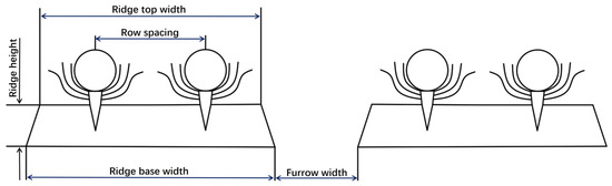
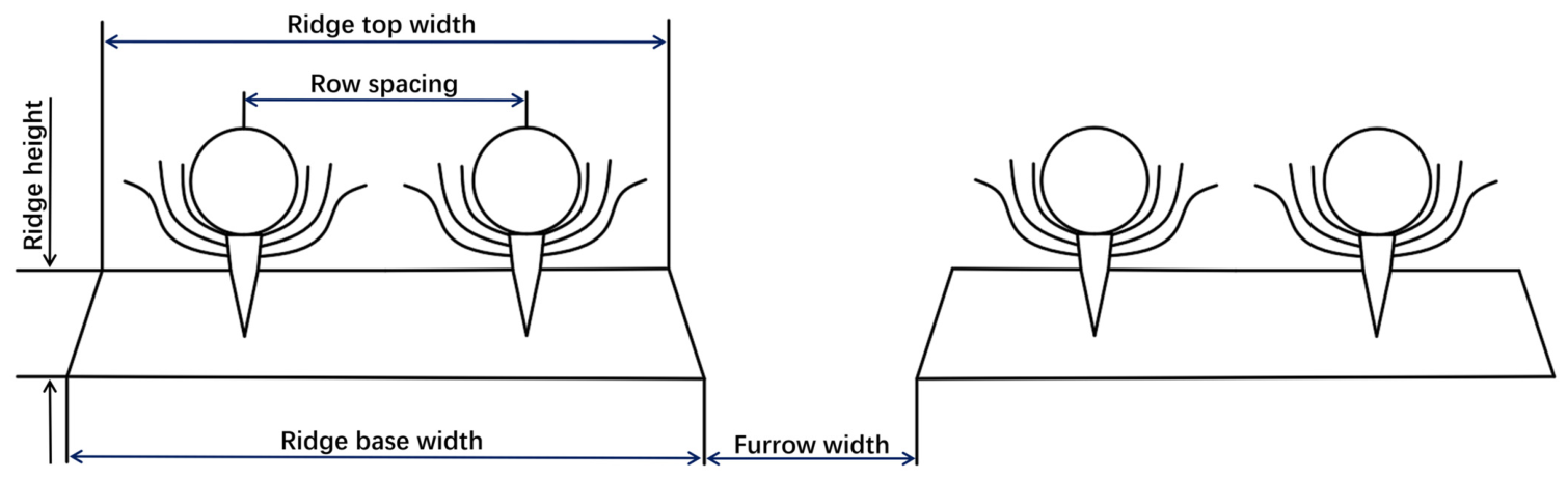
The main cabbage cultivation pattern in Jiangsu Province is ridge planting, as shown in Figure 1. Two rows of cabbages are planted on each ridge. The row spacing and plant spacing are both 400 mm. The ridge top width is 800 mm, the ridge bottom width is 900 mm, the ridge height is 150 mm, and the furrow width is 300 mm. Based on the main cabbage cultivation pattern, a structural configuration with a crawler chassis drive and two-row harvesting was adopted. Compared with side-mounted cabbage harvesters, the crawler chassis drive slightly increases the cost but eliminates the need for tractor hitching, making the machine easier to operate and more compact in structure. In addition, it provides a smaller turning radius, better field trafficability, and stronger adaptability to complex field operating conditions. Although the mechanical structure of the two-row harvesting system is more complex than that of single-row harvesters, it can significantly improve harvesting efficiency.
Figure 1.
Cabbage cultivation pattern in Jiangsu Province.
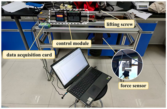
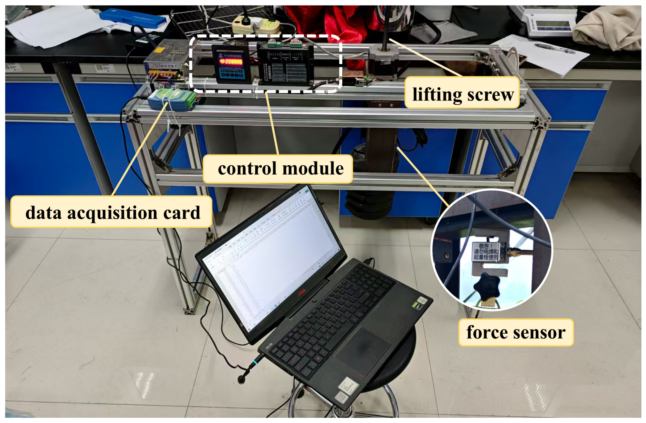
To provide data support for the research and development of cabbage harvesters, this study measured the physical morphological parameters of cabbage. To determine the force required to pull cabbage out of the soil, a pull-out force test bench was used to conduct pull-out force measurement experiments. The pull-out force test bench consists of a data acquisition card (Wuhan Yawei Electronic Technology Co., Ltd., Wuhan, China), a control module, a lifting screw, a force sensor, and other components. The model of the force sensor is GJBLS-I, with a measuring range of 0–50 kg and an analog output of 0–10 V DC voltage signal. First, the force sensor was calibrated using the direct weight loading method, as shown in Figure 2. The calibration data were fitted, and the fitting result was:
where y is the output mass of the force sensor, kg; x is the mass of the loaded weight, kg.
Figure 2.
Calibration process of the force sensor.
Thus, the pulling force of cabbage can be calculated as follows:
where is the maximum pulling force, N; the constant coefficient of 5 is the sensor coefficient (50 kg/10 V), which is used to convert the voltage signal (0–10 V) into mass (0–50 kg), kg/V; and is the maximum output voltage signal, V.
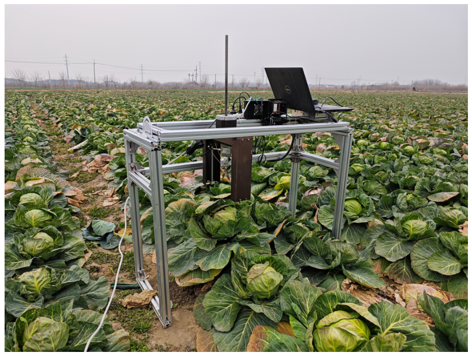
Figure 3 shows the field test for measuring the pulling force of cabbage. During the test, a rope was wrapped around the bottom of the cabbage head and connected to the force sensor with a hook. The force sensor was fixed at the end of the lead screw. The driver controlled the screw motor to start, driving the lead screw to move upward and pull the cabbage from the soil, while the data acquisition card recorded the pulling force.
Figure 3.
Measurement process of cabbage pulling force.
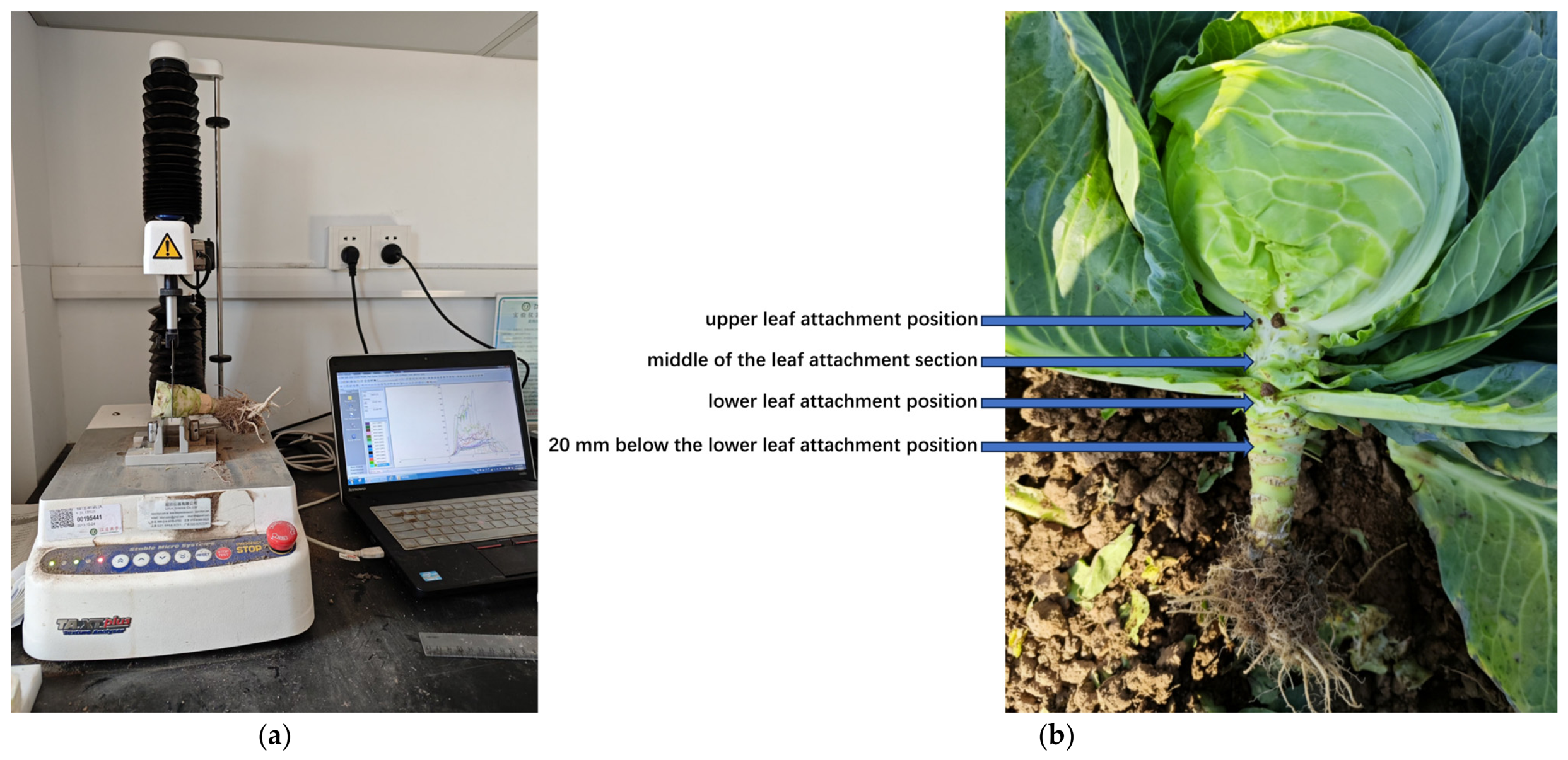
To determine the root cutting force of cabbage, cutting tests were conducted using a texture analyzer (TA. XT plus, SMS, Godalming, UK) with a measuring range of 0–50 kg and an accuracy of 0.1 g. Root cutting force tests were conducted at the upper leaf attachment position, the middle of the leaf attachment section, the lower leaf attachment position, and 20 mm below the lower leaf attachment position of cabbage. The corresponding locations of these positions on the cabbage are shown in Figure 4.
Figure 4.
Distribution of measurement positions and experimental process for specific cutting resistance of cabbage roots: (a). experimental process; (b). distribution of measurement positions.
During the measurement of cabbage root cutting force, specific cutting resistance was adopted as the evaluation index to eliminate the influence of structural variability in cabbage roots. The specific cutting resistance is defined as the cutting force per unit cross-sectional area, i.e., the ratio of the applied cutting force to the cross-sectional area of the cabbage root at the cutting position during the cutting process.
2.2. Overall Structure and Working Principle
2.2.1. Overall Structure
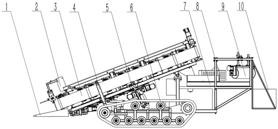
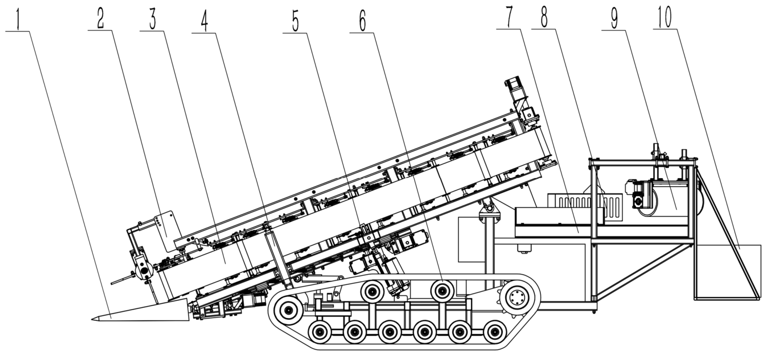
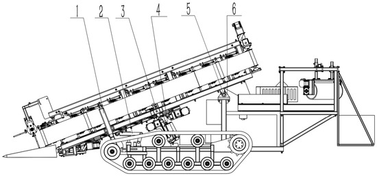
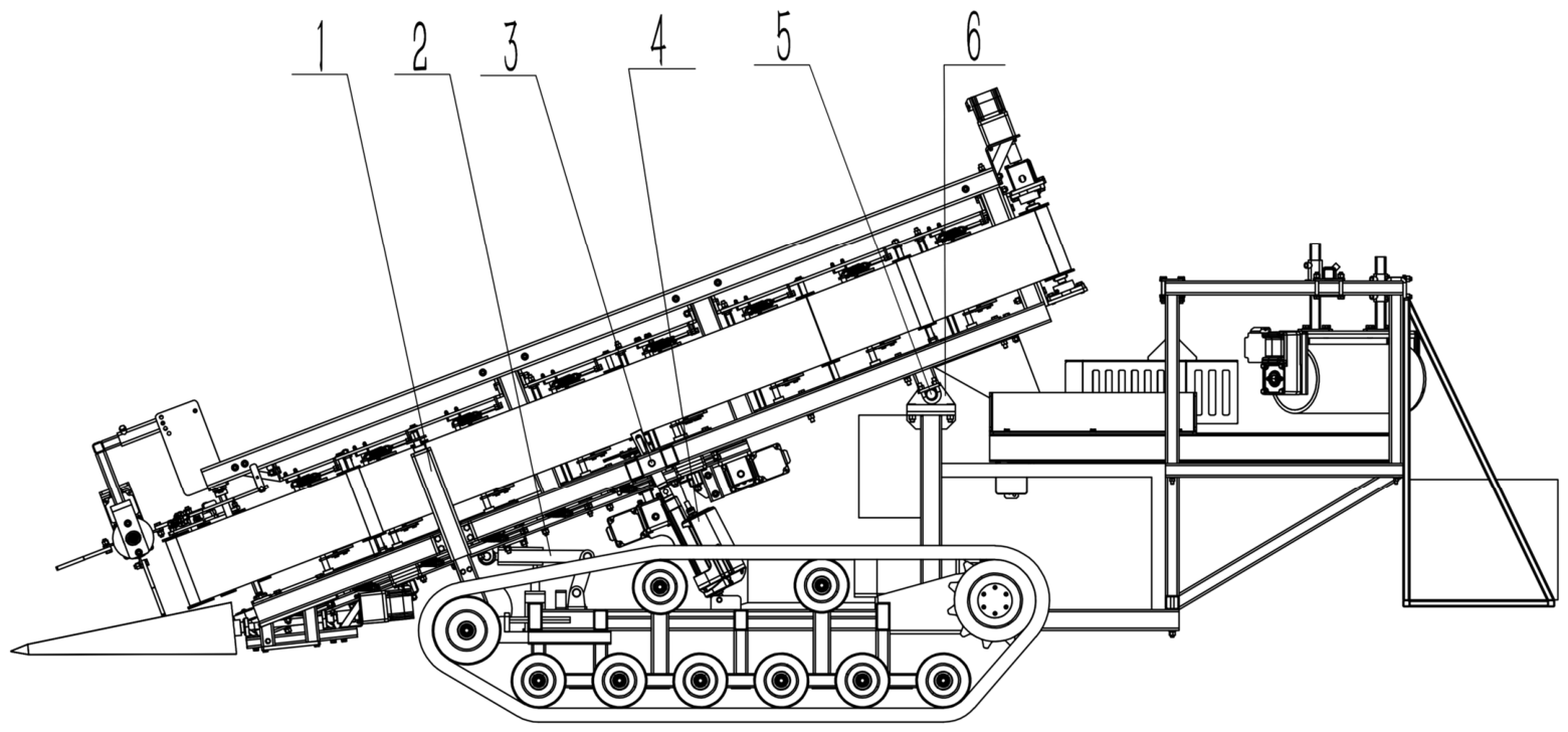
Based on the cabbage cultivation agronomic practices in Jiangsu Province and the characteristics of cabbage harvesting machinery both domestically and internationally, the overall structural configuration of a crawler self-propelled two-row cabbage harvester was determined, as shown in Figure 5. The machine mainly consists of a crawler power chassis, a pulling device, a crop guiding device, a clamping and conveying device, a profiling device, a root cutting device, and a leaf-stripping and collecting device. The leaf-stripping and collecting device includes a conveyor belt, a diversion baffle, a leaf-stripping roller mechanism, and a collecting frame. The machine can complete the operations of pulling, conveying, root cutting, outer leaf separation, and collection of two rows of cabbages in a single pass, thereby improving harvesting efficiency.
Figure 5.
Structural diagram of the crawler self-propelled two-row cabbage harvester. 1. Pulling device; 2. crop guiding device; 3. clamping and conveying device; 4. profiling device; 5. root cutting device; 6. crawler power chassis; 7. conveyor belt; 8. diversion baffle; 9. leaf-stripping roller mechanism; 10. collecting frame.
2.2.2. Working Principle and Technical Parameters
During cabbage harvesting, as the crawler self-propelled two-row cabbage harvester moves forward, the pulling device extracts the cabbages from the soil. The crop guiding device assists the pulling device in feeding the extracted cabbages into the clamping and conveying device. The clamping and conveying device consist of a cabbage-head-clamping conveyor and a root-clamping conveyor, which simultaneously clamp the cabbage head and root-stem part. The conveying line speeds of the two conveyors are identical, ensuring the stability of the cabbage posture during the conveying process. The root cutting device is located below the cabbage-head-clamping conveyor and the root-clamping conveyor and is used to cut off the cabbage roots. After the root-cutting operation is completed, the cabbages continue to move backward under the clamping and conveying action of the cabbage-head-clamping conveyor. At the end of the conveyor, the cabbages are thrown onto a horizontal conveyor belt. Driven by the horizontal conveyor belt, the cabbages move backward and are separated by diversion plates during the conveying process, causing them to move toward the outer sides of the conveyor belt. When the cabbages reach the end of the horizontal conveyor belt, they collide and rub with the leaf-stripping roller mechanism. The loose outer leaves are stripped off and continue to move backward with the conveyor belt, eventually being thrown onto the ground. Under the impact of the leaf-stripping rollers, the cabbages move toward the inner side of the horizontal conveyor belt and continue moving backward with the conveyor until they finally fall into the collecting frame centrally arranged beneath the end of the horizontal conveyor belt. The main technical parameters of the crawler self-propelled two-row cabbage harvester are shown in Table 1.
Table 1.
Technical parameters of the crawler self-propelled two-row cabbage harvester.
2.3. Structural Design of the Pulling Device
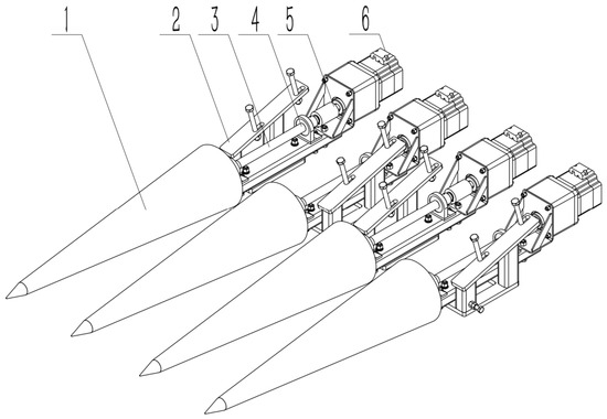
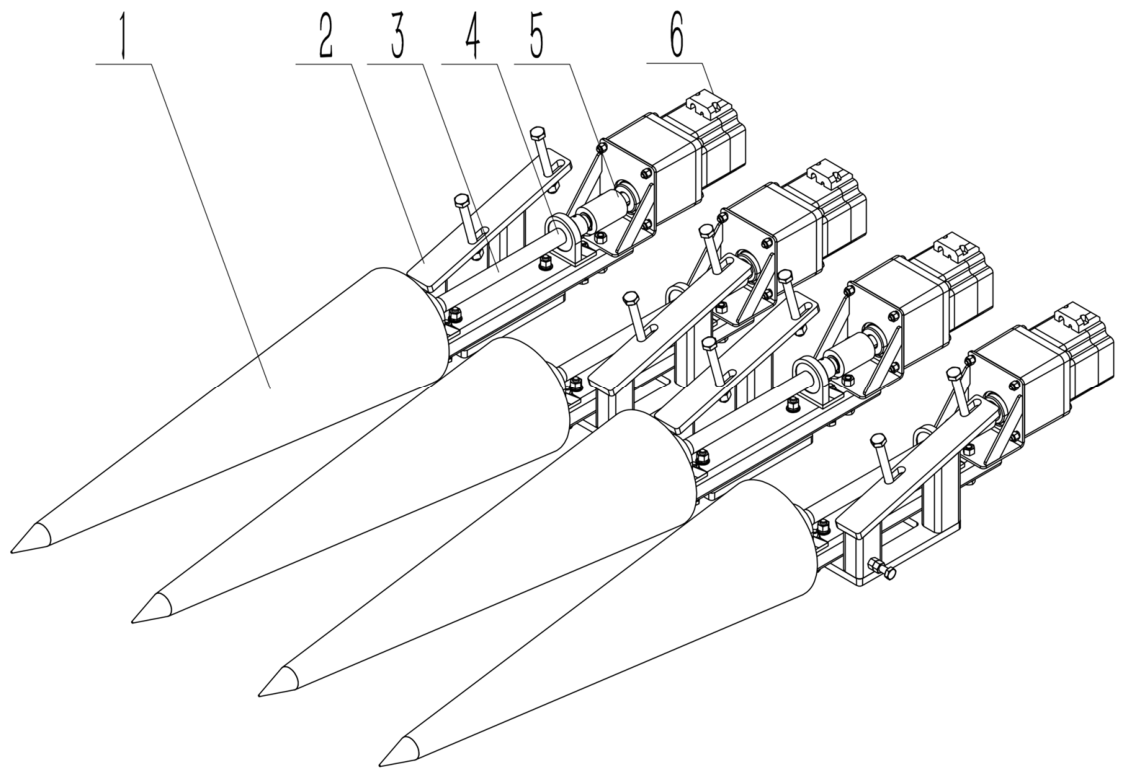
Based on the advantages and limitations of commonly used pulling devices described previously, a conical-type pulling device was selected to reduce mechanical damage to cabbages during harvesting. The pulling device is mounted below the clamping and conveying device by bolts and mainly consists of conical pulling rollers, a mounting frame, rotating shafts, bearing seats, couplings, and motors, as shown in Figure 6. The rotating shafts are installed at the ends of the conical pulling rollers, while the bearing seats and motors are fixed to the mounting frame by bolts. The couplings are used to connect the rotating shafts with the motors. Four conical pulling rollers are arranged in parallel. Every two rollers form one cabbage pulling unit for extracting a single cabbage. Two pulling units are arranged side by side, and the center distance between the two units corresponds to the cabbage planting row spacing of 400 mm.
Figure 6.
Structural diagram of the pulling device. 1. Conical pulling roller; 2. mounting frame; 3. rotating shaft; 4. bearing seat; 5. coupling; 6. motor.
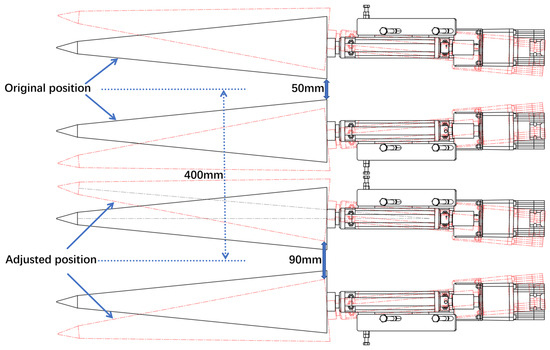
The end spacing between the two conical pulling rollers can be adjusted within a range of 50–90 mm, enhancing the adaptability of the cabbage pulling unit to different cabbage varieties and head diameters. As the end spacing is adjusted, the opening at the front end of the conical pulling rollers gradually increases. During cabbage harvesting, as the harvester moves forward, cabbages that are off-center are gradually guided toward the roller ends, without affecting the normal pulling and feeding into the clamping and conveying device. This design effectively reduces the requirement for row straightness in cabbage planting, as shown in Figure 7.
Figure 7.
Schematic diagram of the adjustable spacing of the conical pulling rollers.
2.4. Structural Design and Kinematic Analysis of the Clamping and Conveying Device
2.4.1. Structural Design
Regarding the conveying system, to enhance cabbage stability during transport, prevent compression damage, and improve root-cutting accuracy, a vertical belt conveying system was chosen. To further improve stability during clamping and conveying, the roots of cabbages are also clamped, forming a dual-layer vertical belt clamping and conveying device. The two layers consist of a cabbage head-clamping and conveying mechanism and a root-clamping and conveying mechanism. During harvesting, cabbages that have been pulled from the soil are clamped at both the head and the roots and conveyed rearward, with the line velocities of the two mechanisms synchronized to maintain cabbage orientation. When cabbages reach the root-cutting device, the stable posture ensures accurate root cutting and high-quality harvest. After root cutting, cabbages are further conveyed to the leaf-stripping and collection device for the removal of outer leaves and collection.
The cabbage head-clamping and conveying mechanism consists of a cabbage head swinging roller set, frame, motor, drive shaft, reversing gearbox, driving roller set, conveying trough, supporting roller set, belt tensioning roller set, belt, and driven roller set, as shown in Figure 8. The belt is tensioned by the cabbage head swinging roller set, supporting roller set, belt tensioning roller set, and driven roller set, and rotates under the drive of the driving roller set.
Figure 8.
Structural diagram of the cabbage head-clamping and conveying mechanism. 1. Swinging roller set of the cabbage head-clamping mechanism; 2. frame; 3. motor; 4. drive shaft; 5. reversing gearbox; 6. driving roller set; 7. conveying trough; 8. supporting roller set; 9. belt tensioning roller set; 10. belt; 11. driven roller set.
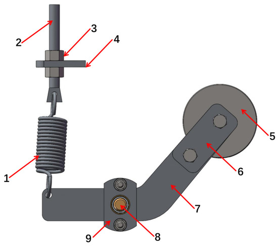
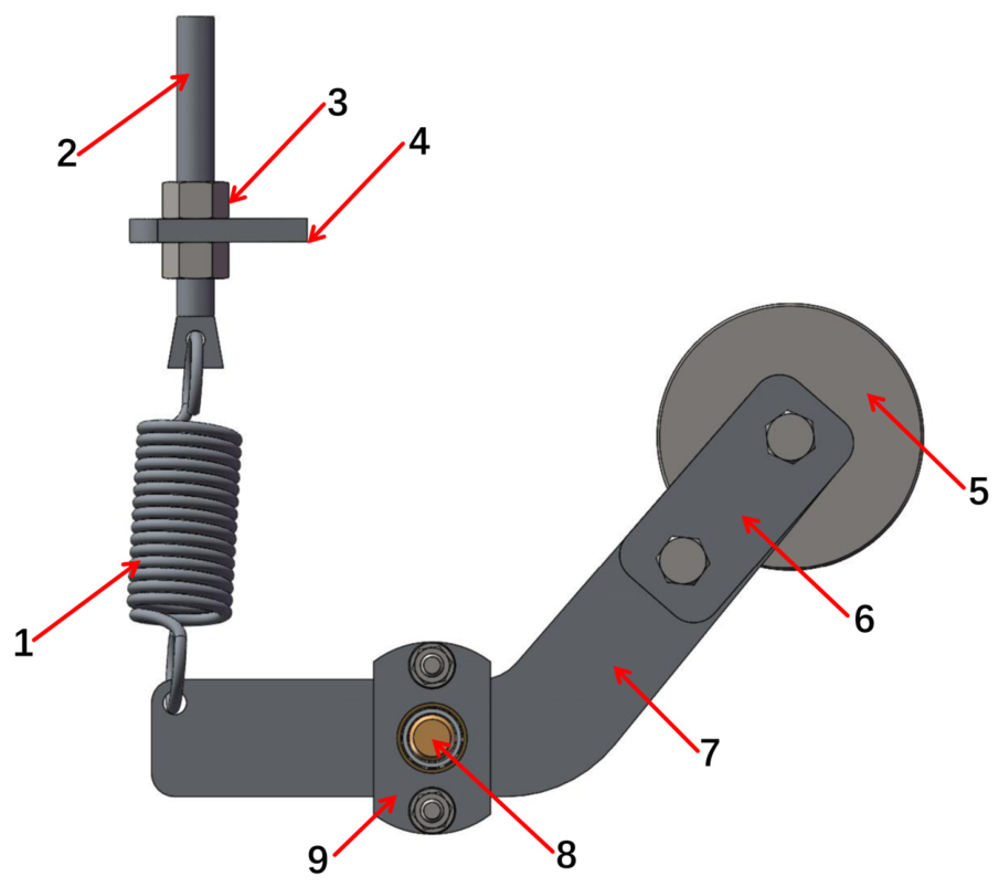
The cabbage head swinging roller set consists of springs, adjustment screws, nuts, screw mounting plates, swinging rollers, covers, swing arms, swing shafts, and bearing seats, as shown in Figure 9. The swinging rollers are pre-tensioned by springs via the adjustment screws to support the belt. When a cabbage passes through, the swinging rollers are pushed aside by the cabbage head and rotate around the swing shaft while stretching the springs. After the cabbage passes, the springs pull the swinging rollers back to their original positions. This mechanism allows the belt to remain tensioned when no cabbage passes through, provides a widened passage for the cabbage during harvesting, and returns the rollers to their original position after the cabbage has passed.
Figure 9.
Structural diagram of the cabbage head swinging roller set. 1. Spring; 2. adjustment screw; 3. nut; 4. screw mounting plate; 5. swinging roller; 6. cover; 7. swing arm; 8. swing shaft; 9. bearing seat.
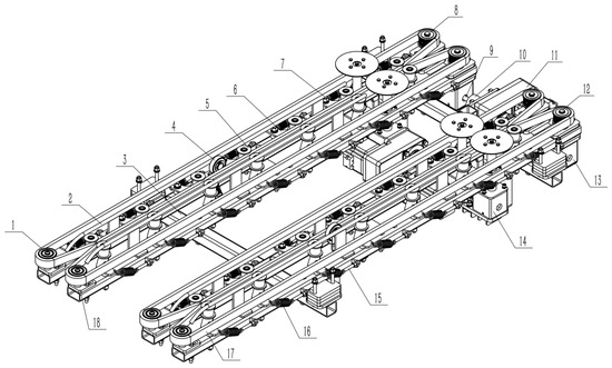
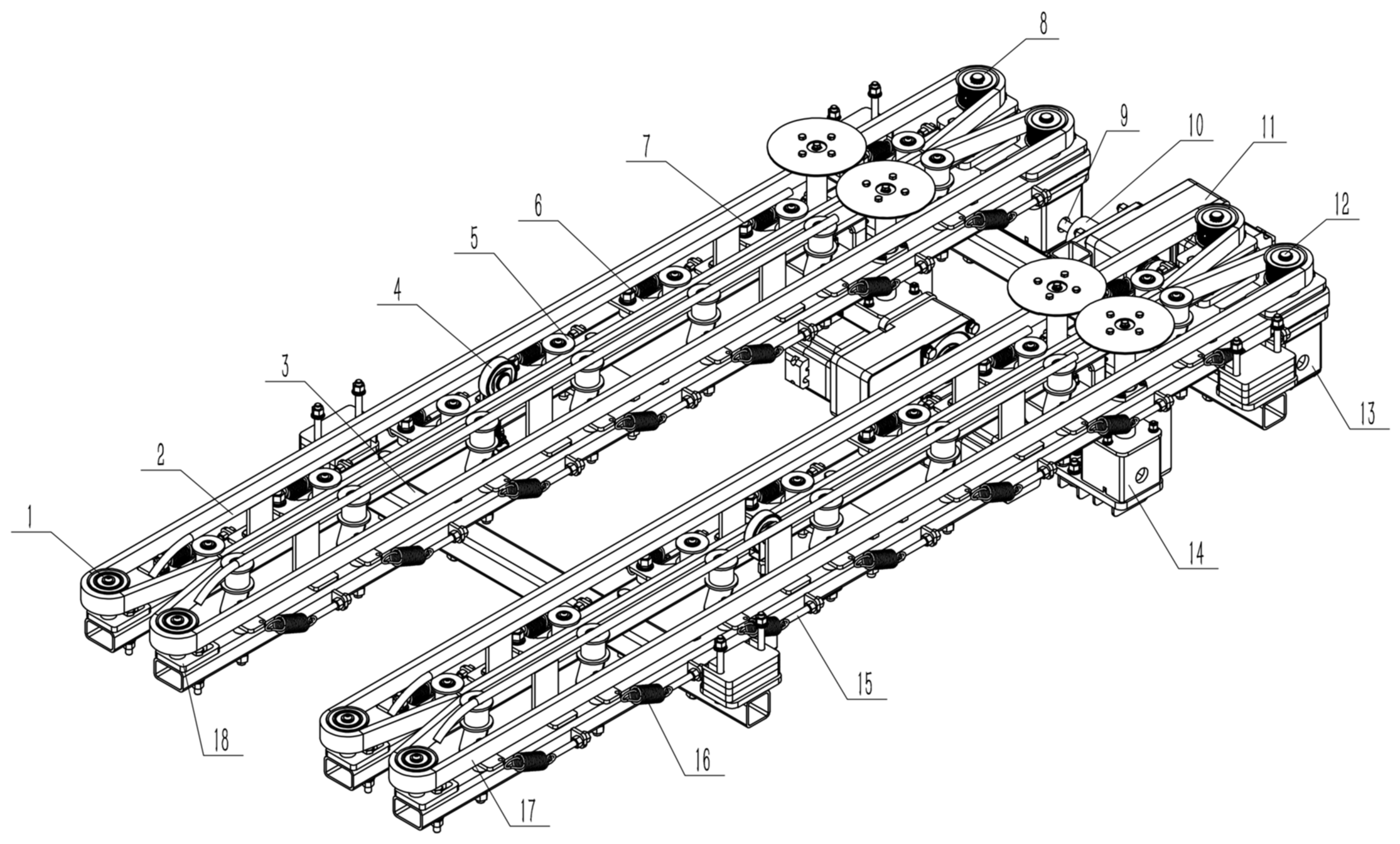
The root-clamping and conveying mechanism consists of a driven roller, guide rod, frame, reciprocating displacement sensor, swinging roller, swing arm, swing shaft, driving roller, drive shaft, coupling, motor, driving shaft, reversing gearbox, root cutting device, adjustment screw, spring, synchronous belt, and tension adjustment plate, as shown in Figure 10. Among these components, the reciprocating displacement sensor is used to measure the root cutting position of the cabbage. The swinging roller, swing arm, swing shaft, adjustment screw, and spring form the root-clamping swinging roller set, which is used to clamp and convey the cabbage root. Its working principle is similar to that of the cabbage head swinging roller set.
Figure 10.
Structural diagram of the root-clamping and conveying mechanism. 1. Driven roller; 2. guide rod; 3. frame; 4. reciprocating displacement sensor; 5. swinging roller; 6. swing arm; 7. swing shaft; 8. driving roller; 9. drive shaft; 10. coupling; 11. motor; 12. driving shaft; 13. reversing gearbox; 14. root cutting device; 15. adjustment screw; 16. spring; 17. synchronous belt; 18. tension adjustment plate.
2.4.2. Kinematic Analysis
To ensure that the cabbage maintains a stable posture during the conveying process, the linear velocities of the cabbage head-clamping mechanism and the root-clamping mechanism must be equal:
where is the linear velocity of the cabbage head-clamping mechanism, m/s; is the linear velocity of the root-clamping mechanism, m/s; is the rotational speed of the driving roller of the cabbage head-clamping mechanism, with a range of 0–200 r/min; is the radius of the driving roller of the cabbage head-clamping mechanism, which is 0.035 m; is the rotational speed of the driving roller of the root-clamping mechanism, with a range of 0–240 r/min; is the radius of the driving roller of the root-clamping mechanism, which is 0.0314 m. Based on the above parameters, the relationship between the rotational speeds of the driving rollers of the cabbage head-clamping mechanism and the root-clamping mechanism can be obtained as follows:
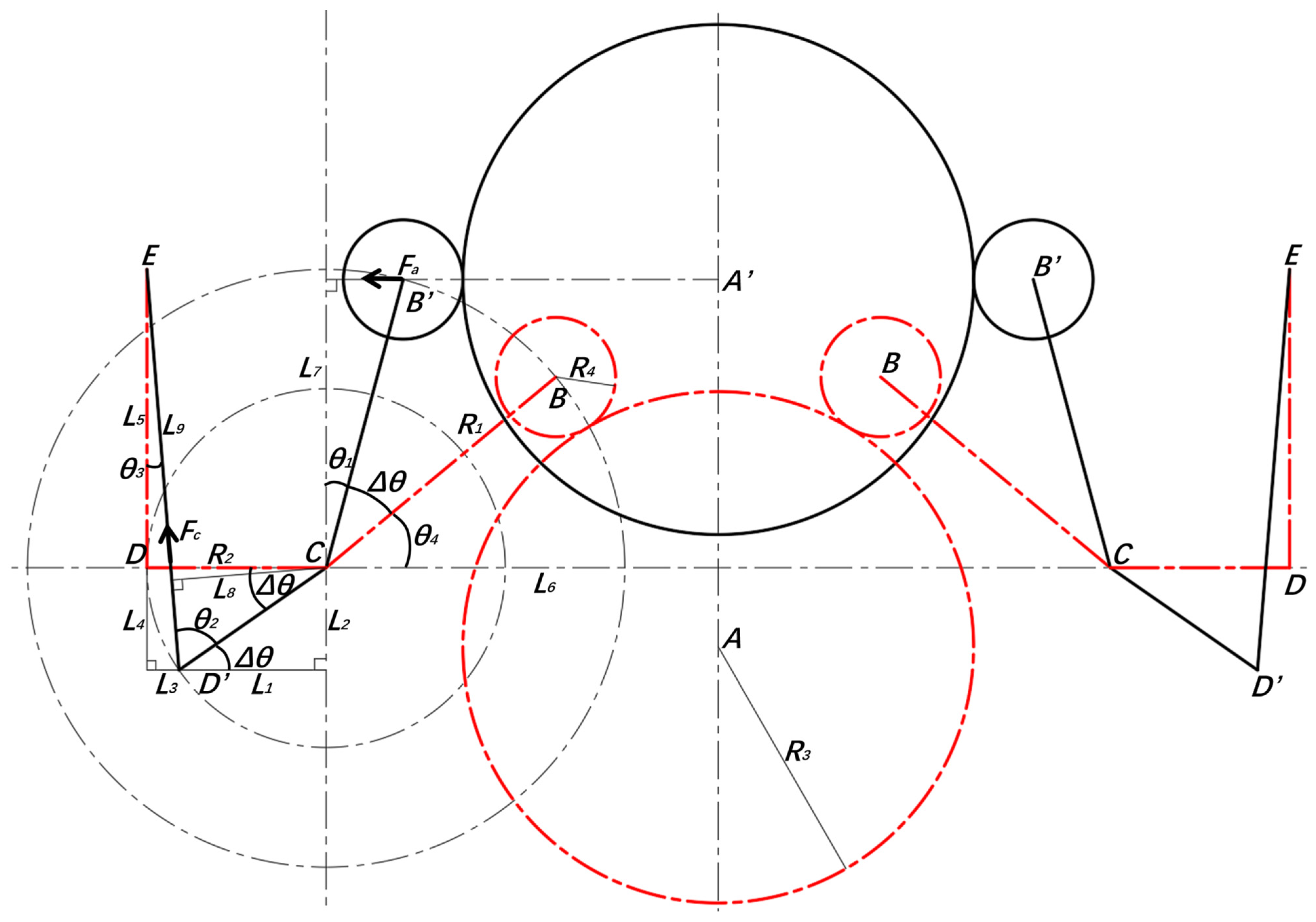
The cabbage head-clamping mechanism is used to clamp the cabbage head. While ensuring stable clamping and conveying of the cabbage, the compressive force exerted by the belt on the cabbage should be minimized to prevent mechanical damage caused by excessive compression. To analyze the clamping force exerted by the belt of the cabbage head-clamping mechanism during the conveying process, the motion process between the cabbage head swinging roller set and the cabbage is analyzed. The working principle of the cabbage head swinging roller set is illustrated in Figure 11.
Figure 11.
Working principle of the cabbage head swinging roller set.
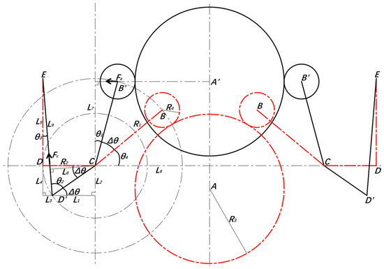
In the figure, AA’ represents the path of cabbage clamping and conveying, which is the centerline between the two belts. A is the center of the cabbage, B is the center of the swinging roller, C is the center of the swing shaft, D is the attachment point of the spring on the swing arm, and E is the attachment point of the spring on the adjustment screw. The red dashed line indicates the state when the cabbage just contacts the swinging roller, and the black solid line indicates the state when the center of the cabbage is aligned with the center of the swinging roller. At this moment, the spring is fully stretched, and the belt, supported by the swinging roller set, exerts the maximum clamping force on the cabbage. The moment balance on the swing arm is given by:
where is the force exerted on the supporting roller, N; is the moment arm of the force of the cabbage on the supporting roller, mm; is the spring force, N; is the moment arm of the spring force on the cabbage, mm; is the swing radius of the swinging roller, which is 100 mm; is the angle between B’C and the vertical direction; is the swing radius of the swing arm, which is 60 mm, and is the angle between the spring ED’ and the swing arm D’C.
The angle between B’C and the vertical direction is given by:
where is the distance from the rotation center of the swing arm to the cabbage conveying centerline AA’, which is 131.3 mm; is the radius of the cabbage; and is the radius of the swinging roller, which is 20 mm.
The angle between the spring ED’ and the swing arm D’C is given by:
where is the angular displacement of the swinging roller set from the dashed line position to the solid line position, °; is the angular displacement of the spring from the dashed line position to the solid line position, °; and is the angle between the swing arm BC and the horizontal direction in the solid line state, which is 40°.
The angular displacement of the spring from the dashed line position to the solid line position is given by:
where is the length of the spring in the dashed line state, which is 100 mm, and is the angular displacement of the spring from the dashed line state to the solid line state, °.
The spring force is given by:
where is the elongation of the spring, mm; is the spring stiffness, N/mm; is the initial spring force, which is 9.42 N, is the length of the spring in the solid line state, mm; is the stiffness per coil of the spring, which is 19.8 N/mm, and is the number of effective coils of the spring, which is 18.
The force exerted by the supporting roller on the cabbage is the reaction force of the cabbage on the supporting roller, which is equivalent to the compressive force of the belt on the cabbage. When the cabbage radius is determined, the belt pressure on the cabbage can be calculated using the procedure described above. For a maximum harvested cabbage diameter of 200 mm, the belt exerts the maximum compressive force on the cabbage. To ensure that the cabbage does not fall during clamping and conveying, the following condition must be satisfied:
where is the friction force of the belt on the cabbage, N; is the coefficient of friction between the belt and the cabbage, which is 0.42, and is the normal pressure of the belt on the cabbage, N.
The pressure of the belt on the cabbage was calculated as 38.71 N, which is far below the threshold at which the cabbage would suffer compression damage, thereby ensuring that the cabbage is not damaged during clamping and conveying. Based on preliminary experiments, the coefficient of friction between the belt and the cabbage was measured as 0.42, resulting in a belt friction force of 32.52 N. Based on the previously measured maximum mass of the cabbage, which is 2.89 kg, the condition for preventing the cabbage from falling during clamping and conveying is satisfied.
At this moment, the elongation of the spring also reaches its maximum. The calculated spring length is 142.27 mm. To prevent the maximum elongation from exceeding the deformation limit of the spring under the extreme load, which would affect the service life of the spring, the following condition must be satisfied:
where is the length of the spring under the extreme load, mm; is the free length of the spring, mm; is the deformation of the spring under the extreme load, mm; is the deformation per coil under the extreme load, which is 5.939 mm; is the diameter of the spring material, which is 2 mm; and is the mean diameter of the spring, which is 20 mm.
Based on the above equation, the length of the spring under the extreme load was calculated as 163.52 mm, which ensures that the spring elongation remains below the deformation limit of the spring under the extreme load.
2.5. Structural Design of the Profiling Device
During open-field ridge planting of cabbages, uneven ridge surfaces are inevitable. During operation, the harvester must ensure that the pulling device maintains close contact with the ground to perform cabbage extraction. When the ridge surface fluctuates, the cutter unit height must be adjusted to adapt to these variations. If the cutter unit height cannot be adjusted during operation, a high ridge may cause the pulling device to penetrate the soil, potentially damaging the device due to soil resistance. Conversely, a low ridge may cause the pulling device to lift off the ground, pushing the cabbage and leading to extraction failure or damage to the cabbage head. To address this issue, a profiling device was designed. This device consists of a profiling roller lifting mechanism, support arm, pin shaft, electric pushrod, mounting shaft, and spherical bearing seat, as shown in Figure 12. The profiling device, in conjunction with the crawler power chassis, can effectively enhance the harvester’s adaptability to soft and wet field soil conditions, ensuring stable operation during cabbage harvesting [36].
Figure 12.
Structural diagram of the profiling device. 1. Profiling roller lifting mechanism; 2. support arm; 3. pin shaft; 4. electric pushrod; 5. mounting shaft; 6. spherical bearing seat.
The cutter unit is hinged to the chassis of the crawler through the mounting shaft and spherical bearing seat. The bottom of the electric pushrod is hinged to the crawler chassis via a pin shaft, while its head, in a long-slot configuration, is connected to the cutter unit frame through another pin shaft. The spherical bearing at the front end of the support arm is hinged to the cutter unit frame, which helps reduce the lateral swing of the cutter unit. During transport, the cutter unit needs to be raised to increase ground clearance and improve the harvester’s mobility. When the electric pushrod extends and the bottom of the long slot contacts the pin shaft, the cutter unit begins to lift. When the electric pushrod is fully extended, the lowest point of the cutter unit reaches a ground clearance of 400 mm, ensuring sufficient clearance during transport. During harvesting, the electric pushrod is retracted to lower the cutter unit so that the pulling device maintains close contact with the ground. Simultaneously, the profiling roller lifting mechanism is adjusted so that the profiling roller contacts the ground and supports the cutter unit. At this point, the bottom of the long slot on the electric pushrod disengages from the pin shaft on the cutter unit. As the harvester moves forward, the profiling roller rolls along the ridge surface. When the ridge surface changes in height along the forward–backward direction, the mounting shaft on the cutter unit adjusts its forward–backward angle in the spherical bearing seat. When the ridge surface changes in height along the lateral direction, the mounting shaft adjusts its lateral angle within the spherical bearing seat. The maximum lateral angular variation is ±9°, and, for an 800 mm wide ridge, the cutter unit can accommodate a lateral height variation of ±63.4 mm. This design allows the cutter unit to automatically adjust its height and angle according to the shape of the ridge during harvesting, improving the quality of the operation and reducing harvest losses.
2.6. Structural Design of the Leaf Stripping and Collection Device
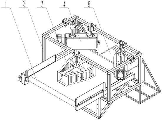
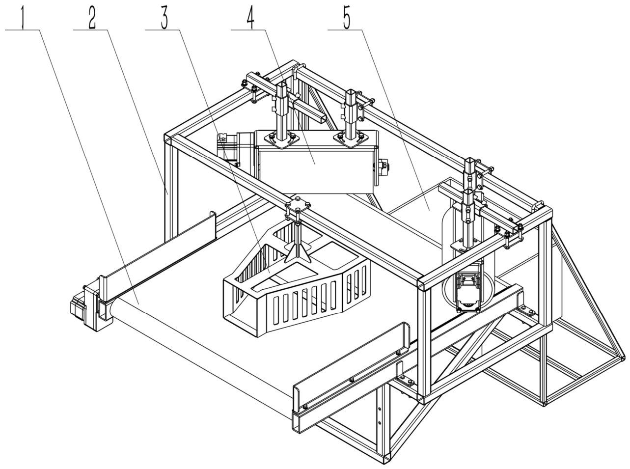
The leaf stripping and collection device consists of a conveyor belt, frame, diverter plate, leaf stripping roller mechanism, and collection box, as shown in Figure 13. A 10 mm gap is maintained between the diverter plate and the surface of the conveyor belt. The gap between the leaf stripping roller mechanism and the conveyor belt surface is adjustable, and the angle between the leaf stripping roller mechanism and the conveying direction of the conveyor belt can also be adjusted.
Figure 13.
Structural diagram of the leaf stripping and collection device. 1. Conveyor belt; 2. frame; 3. diverter plate; 4. leaf stripping roller mechanism; 5. collection box.
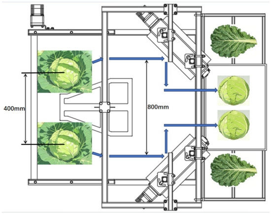
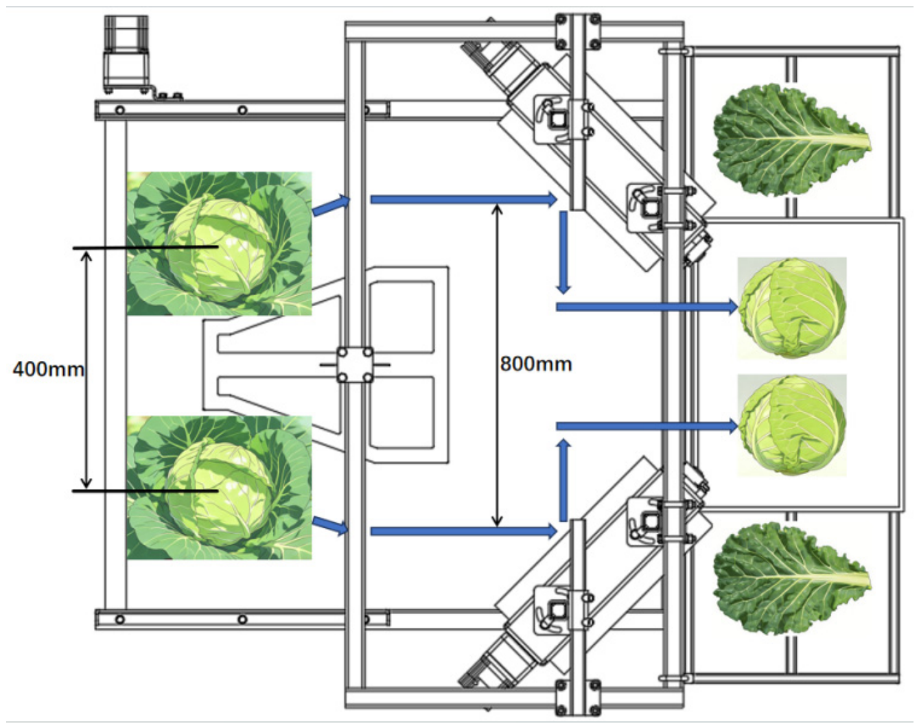
The cabbages with their roots removed are conveyed backward by the cabbage head-clamping mechanism and fall from the end of the clamping belt onto the conveyor belt of the leaf stripping device. At this point, the spacing between cabbages corresponds to the planting row spacing, which is 400 mm. As the cabbages are transported along the conveyor belt, they contact the diverter plate, and the spacing gradually increases to 800 mm. Under the combined action of the conveyor belt and the leaf stripping roller mechanism, the loose outer leaves of the cabbages are separated from the heads through friction and collision, falling onto the conveyor belt. The stripped cabbages continue to move backward along the conveyor belt through the gap between the leaf stripping rollers and the belt, ultimately falling onto the previously harvested ridge surface. The cabbage heads, after losing their loose outer leaves, are first rotated perpendicular to the conveying direction due to collisions with the leaf stripping rollers and then continue to move backward with the conveyor belt, eventually falling into the collection box. This process achieves the removal of the outer leaves. The movement of cabbages in the leaf stripping and collection device is illustrated in Figure 14.
Figure 14.
Movement process of cabbages in the leaf stripping and collection device.
2.7. Single-Factor Experiments on Factors Affecting Cabbage Harvest Qualification Rate
2.7.1. Experimental Conditions
The field experiment was conducted from 20 to 23 December 2025 at the Hengtang Vegetable Professional Cooperative in Changshu City, Jiangsu Province. The cabbage was planted on a total area of 20 mm using a double-row ridge planting system, with a row spacing of 400 mm, plant spacing of 400 mm, ridge width of 800 mm, ridge base width of 900 mm, ridge height of 150 mm, and furrow width of 300 mm. The cabbage variety used in the experiment was “Aoqina”(Takii & Co., Ltd., Kyoto, Japan), with a growth period of approximately 65–75 days. The cabbage heads were oblate spheroid in shape and compactly formed, with an average transverse diameter of 180.2 mm, an average longitudinal diameter of 114.95 mm, and an average plant spread of 625.05 mm. The average mass of the cabbage head (after removing roots and outer leaves, representing the marketable portion) was 1.6 kg. The variety exhibited good heat tolerance and strong cold resistance.
2.7.2. Experimental Methods and Evaluation Indicators
The field harvesting experiment of the crawler-type self-propelled double-row cabbage harvester was conducted in accordance with the relevant Chinese national standards, including GB/Z 26582-2011 [37]: Production technical practice for cabbage and NY/T 4073-2022 [38]: Technical code of practice for mechanized production of cabbage. For each trial, 100 consecutive cabbages were selected as a sample, and the number of cabbages meeting the harvesting and leaf-stripping standards was recorded. Each sample was tested five times, and the mean of the five replicates was taken as the final experimental result.
The mechanized harvesting standards for cabbages are as follows: harvesting should be performed after the heads are compact; 2–3 outer leaves should be retained after harvest; the root-cutting surface should be smooth; and the cabbage head surface should be clean, free of damage or cracking.
The harvest qualification criteria are: the root-cutting surface must be smooth with no broken roots or stems; the cutting position must be located 20 mm above the lowest leaves of the cabbage, cutting through the outer leaves; and the cabbage surface must be free of compression or cutting damage. The harvest qualification rate was calculated using the following formula:
where N is the harvest qualification rate, %; is the number of cabbages meeting the harvesting standards, and is the total number of harvested cabbages.
Based on the design and analysis of the key components of the crawler-type self-propelled double-row cabbage harvester, the main factors affecting the cabbage harvesting damage rate are the forward speed, pulling roller rotational speed, clamping and conveying speed, and cutter rotational speed. Therefore, in this experiment, the harvest qualification rate was used as the evaluation index, and the forward speed, pulling roller rotational speed, clamping and conveying speed, and cutter rotational speed were selected as experimental factors. By fixing all other factors and varying one factor at a time, the relationship between the harvest qualification rate and each experimental factor was determined. The initial levels of the experimental factors were set as follows: forward speed 0.4 m/s, pulling roller rotational speed 120 r/min, clamping and conveying speed 0.5 m/s, and cutter rotational speed 300 r/min.
2.7.3. Experimental Design
(1) Forward speed single-factor experiment: The pulling roller rotational speed was fixed at 120 r/min, the clamping and conveying speed at 0.5 m/s, and the cutter rotational speed at 300 r/min. The forward speed was varied from 0.2 m/s, increasing by 0.1 m/s for each comparative trial, with a total of 5 groups, reaching a maximum forward speed of 0.6 m/s.
(2) Pulling roller rotational speed single-factor experiment: The forward speed was fixed at 0.4 m/s, the clamping and conveying speed at 0.5 m/s, and the cutter rotational speed at 300 r/min. The pulling roller rotational speed was varied from 40 r/min, increasing by 40 r/min for each comparative trial, with a total of 5 groups, reaching a maximum rotational speed of 200 r/min.
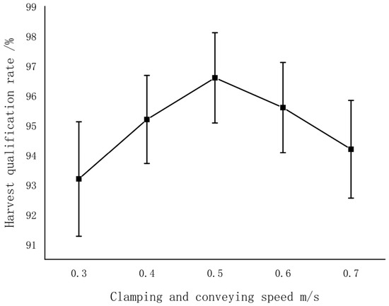
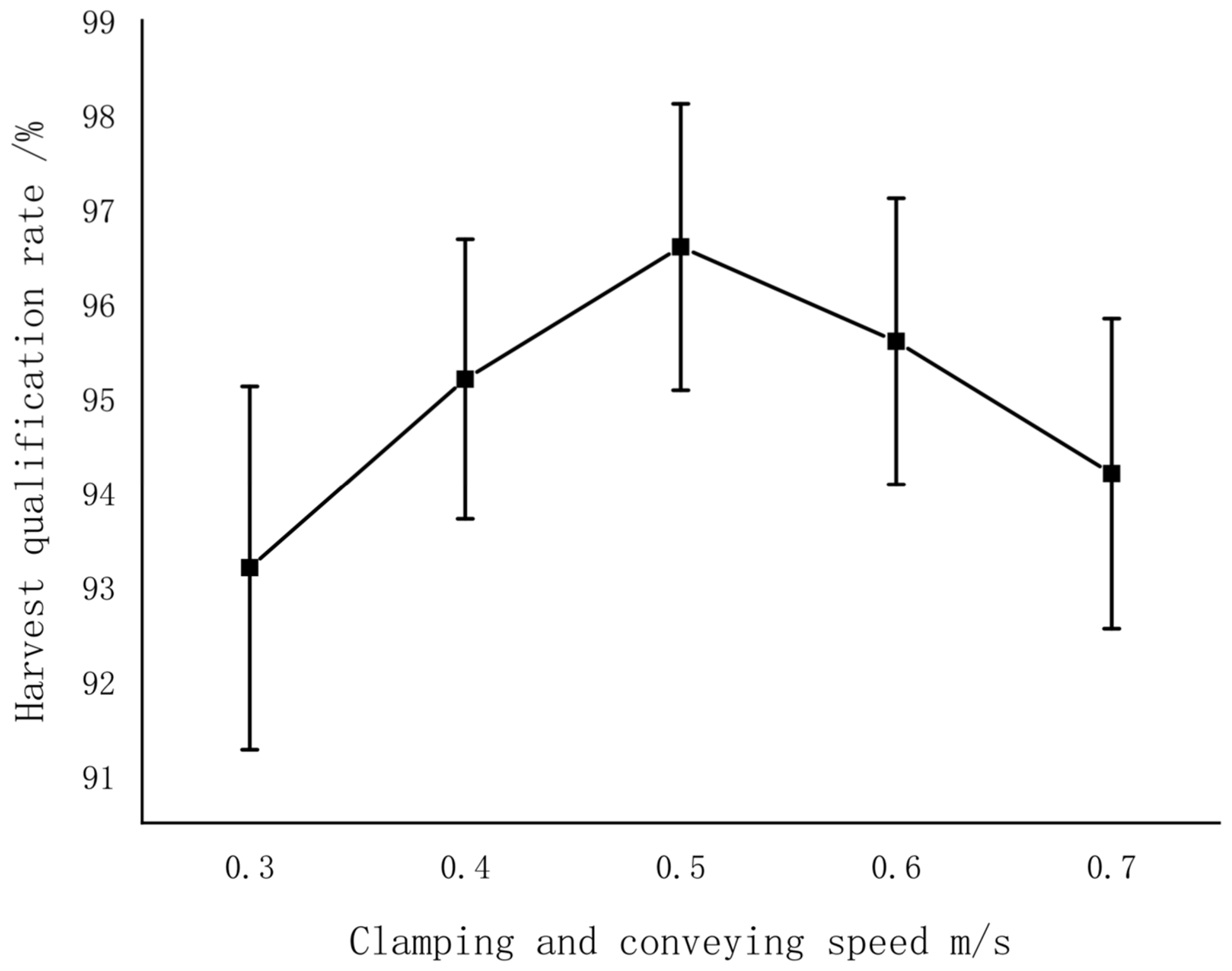
(3) Clamping and conveying speed single-factor experiment: The forward speed was fixed at 0.4 m/s, the pulling roller rotational speed at 120 r/min, and the cutter rotational speed at 300 r/min. The clamping and conveying speed was varied from 0.3 m/s, increasng by 0.1 m/s for each comparative trial, with a total of 5 groups, reaching a maximum clamping and conveying speed of 0.7 m/s.
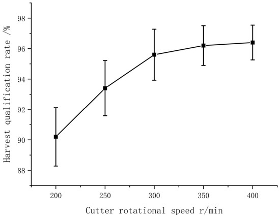
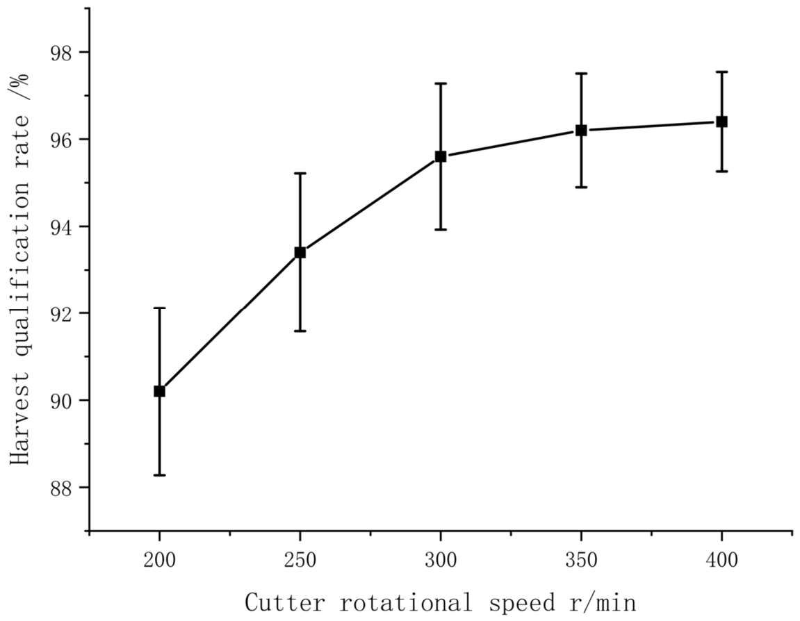
(4) Cutter rotational speed single-factor experiment: The forward speed was fixed at 0.4 m/s, the pulling roller rotational speed at 120 r/min, and the clamping and conveying speed at 0.5 m/s. The cutter rotational speed was varied from 200 r/min, in-creasing by 50 r/min for each comparative trial, with a total of 5 groups, reaching a maximum cutter rotational speed of 400 r/min.
3. Results
3.1. Results of Mechanized Cabbage Harvesting Characteristics
3.1.1. Determination of Cabbage Physical Morphological Parameters
The cabbage variety used in this study was “Aoqina”(Takii & Co., Ltd., Kyoto, Japan). The measured physical morphological parameters of cabbage are shown in Table 2. The transverse diameter of the cabbage head was (180.2 ± 26.48) mm, and the longitudinal diameter was (114.95 ± 19.08) mm. The plant spread was (625.05 ± 115.28) mm, and the plant height was (171.41 ± 28.82) mm. The ground clearance of the lowest leaf was (28.19 ± 17.04) mm, and the length of the main root below the soil surface was (66.55 ± 24.04) mm. The total mass (total mass of cabbage, including roots and outer leaves, directly pulled from the soil) was (2.37 ± 0.6) kg. These measurement results provide data support for the structural design of the cabbage harvester.
Table 2.
Physical morphological parameters of cabbage.
3.1.2. Determination of Cabbage Pulling Force
The measured pulling forces are shown in Table 3. The maximum pulling force was 327.77 N, the minimum was 157.78 N, and the average value was 233.58 N. These results provide data support for the design of the pulling device.
Table 3.
Results of the cabbage pulling force measurement test.
3.1.3. Measurement Results of Specific Cutting Resistance of Cabbage Roots
The experimental results are presented in Table 4. As shown in the table, the specific cutting resistance gradually increases from the upper to the lower leaf attachment position. During cabbage harvesting, the optimal root cutting position should be as close as possible to the upper leaf attachment position while avoiding damage to the cabbage heads. Therefore, the cutting position is generally set at approximately 20 mm below the upper leaf attachment position. At this position, the specific cutting resistance is about 9.93 N/cm2, which not only prevents damage to the cabbage heads but also ensures that most of the outer leaves are removed. Meanwhile, approximately 2–3 outer leaves are retained to protect the cabbage heads and reduce potential damage during transportation.
Table 4.
Experimental results of specific cutting resistance of cabbage roots.
3.2. Results and Analysis of Single-Factor Experiments on Factors Affecting Cabbage Harvest Qualification Rate
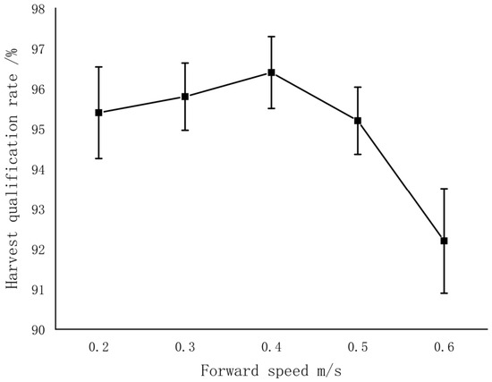
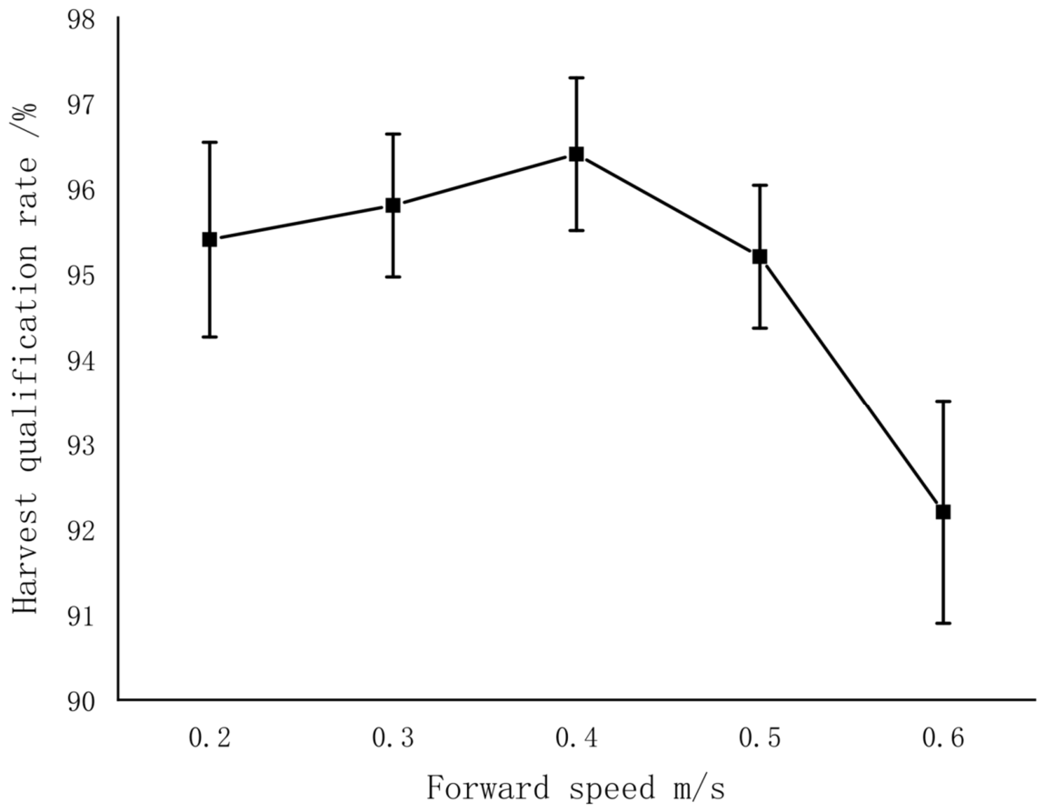
(1) The results of the forward speed single-factor experiment are shown in Figure 15. As illustrated, when the forward speed of the cabbage harvester is in the range of 0.2–0.4 m/s, the harvest qualification rate remains relatively high and stable. When the forward speed exceeds 0.4 m/s, the harvest qualification rate begins to decline, and the rate of decline accelerates with increasing speed. The reason for this trend is that, with a constant clamping and conveying speed, when the forward speed is too high, the horizontal component of the clamping and conveying velocity is smaller than the forward speed. This causes cabbages to accumulate at the end of the pulling rollers, resulting in less smooth feeding into the clamping and conveying device. Cabbages extracted from the soil may not be properly clamped in time and can be pushed by the blades of the crop guiding roller. This changes the orientation of the cabbage during feeding, leading to inaccurate or oblique root cutting, and increases the number of contacts between the blades and the cabbage head, causing surface abrasions and reducing the harvest qualification rate. The forward speed of the harvester determines the harvesting efficiency. At lower forward speeds, the harvest qualification rate is high, but the harvesting efficiency is relatively low. At higher forward speeds, although the harvest qualification rate decreases, the harvesting efficiency improves.
Figure 15.
Results of the forward speed single-factor experiment.
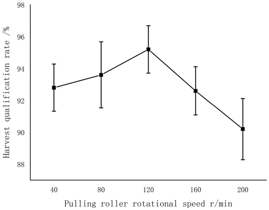
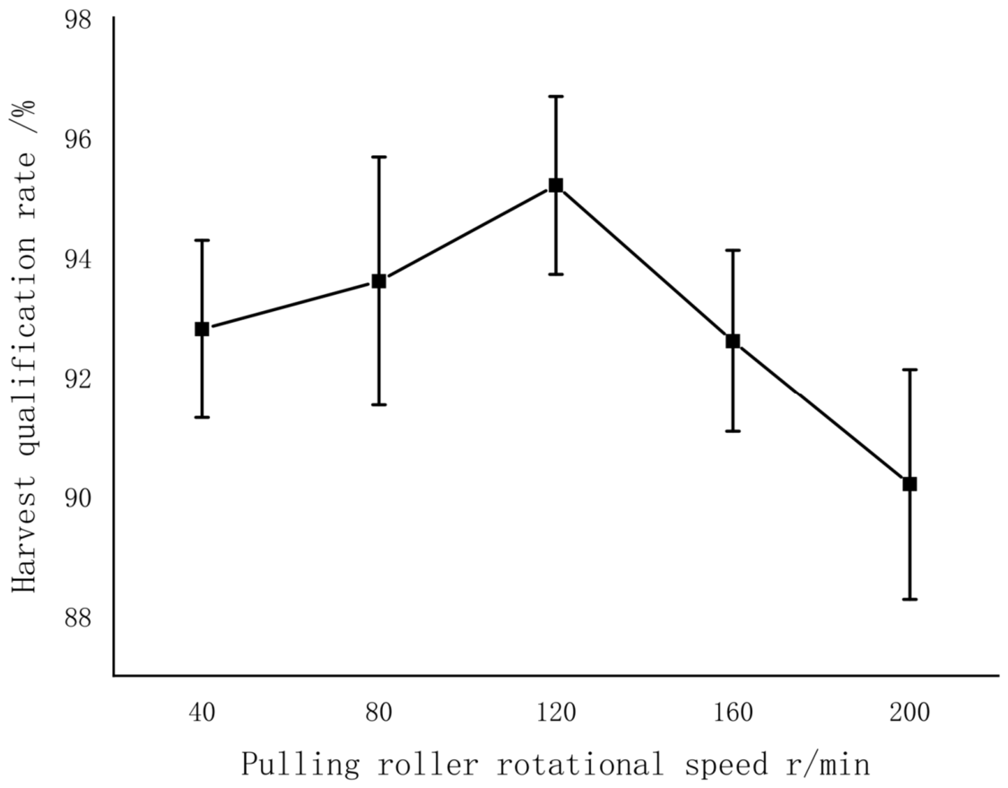
(2) The results of the pulling roller rotational speed single-factor experiment are shown in Figure 16. As illustrated, when the pulling roller rotational speed is below 120 r/min, the outward rotation of the rollers generates insufficient pulling force, causing the cabbages to be pushed upward on the surface of the conical pulling rollers. This results in compression damage at the bottom of the cabbage heads, reducing the harvest qualification rate. When the pulling roller rotational speed is 120 r/min, the harvest qualification rate is relatively high. However, when the rotational speed exceeds 120 r/min, the harvest qualification rate declines. The reason for this is that at higher rotational speeds, the cabbages experience greater friction due to high-speed roller rotation, and the bottom leaves of the cabbage heads suffer more severe abrasion, leading to a reduction in the harvest qualification rate.
Figure 16.
Results of the pulling roller rotational speed single-factor experiment.
(3) The results of the clamping and conveying speed single-factor experiment are shown in Figure 17. As illustrated, with the forward speed maintained at 0.4 m/s, when the horizontal component of the clamping and conveying speed is lower than the forward speed, cabbages tend to accumulate at the end of the pulling rollers before entering the clamping and conveying device. Cabbages extracted from the soil are pushed by the blades of the crop guiding roller, causing changes in the feeding orientation. This may result in inaccurate root cutting positions, oblique cuts, and surface abrasions, reducing the harvest qualification rate. When the clamping and conveying speed is approximately 0.5 m/s, the harvest qualification rate reaches its maximum. However, when the clamping and conveying speed exceeds 0.5 m/s, the harvest qualification rate decreases. This is because, with the cutter rotational speed remaining constant, an increase in clamping and conveying speed reduces the time the cutter acts on the cabbage roots, leading to incomplete root cutting, oblique cuts, and cabbage head overturning, thereby reducing the harvest qualification rate.
Figure 17.
Results of the clamping and conveying speed single-factor experiment.
(4) The results of the cutter rotational speed single-factor experiment are shown in Figure 18. As illustrated, with increasing cutter rotational speed, the harvest qualification rate of cabbages also increases and then gradually stabilizes. When the cutter rotational speed becomes too high, its effect on the harvest qualification rate is minimal, while power consumption increases and the root cutting device experiences greater vibration. Therefore, the cutter rotational speed should not be set excessively high and should only meet the requirements for root cutting.
Figure 18.
Results of the cutter rotational speed single-factor experiment.
3.3. Response Surface Experiment for Cabbage Harvest Qualification Rate
3.3.1. Experimental Design and Results of the Harvest Qualification Rate Response Surface Study
Based on the results of the single-factor experiments, the reasonable ranges of each factor were determined. To obtain the optimal working parameter combination for the crawler-type self-propelled double-row cabbage harvester, the forward speed , pulling roller rotational speed , clamping and conveying speed , and cutter rotational speed were selected as experimental factors, and the cabbage harvest qualification rate y (%) was used as the evaluation index. According to the Box–Behnken design principle, a four-factor, three-level response surface experiment was conducted using the software Design-Expert 13 (Stat-Ease, Inc., Minneapolis, MN, USA). Table 5 presents the coded levels of the experimental factors. The experimental design included 29 trials, comprising five center points for error estimation and 24 factorial points. The design scheme and the results of the response surface regression analysis are shown in Table 6.
Table 5.
Coded levels of experimental factors.
Table 6.
Design scheme and results of the response surface regression analysis.
3.3.2. Analysis of the Harvest Qualification Rate Response Surface Experiment
(1) Model selection.
Based on the experimental data in Table 6, the cabbage harvest qualification rate was analyzed using Design-Expert 13 (Stat-Ease, Inc., Minneapolis, MN, USA). The analysis of variance (ANOVA) results for the regression model is presented in Table 7.
Table 7.
Analysis of variance for the regression model.
As shown in Table 7, the quadratic regression model was found to be significant and is therefore recommended as the appropriate model. Accordingly, a four-factor, quadratic, central composite response surface experimental design was adopted in this study to optimize the parameters of the four factors affecting the cabbage harvest qualification rate. To ensure the validity of the statistical method, diagnostic tests were performed to verify the core assumptions of the ANOVA, namely normality and homogeneity of variance. The Shapiro–Wilk test was applied to the residuals of the ANOVA, indicating that they followed a normal distribution. Levene’s test was subsequently conducted to assess variance homogeneity, and no significant heteroscedasticity was observed. Therefore, the experimental data satisfy the assumptions of normality and homogeneity of variance, confirming the validity of the statistical analysis.
(2) Variance and significance analysis of cabbage harvest qualification rate.
Based on the experimental data in Table 6, the significance of the regression equation was analyzed using Design-Expert 13, and the results are presented in Table 8.
Table 8.
Significance analysis of the regression equation.
According to Table 8, the p-value of the regression model is less than 0.0001, indicating that the model is valid and highly significant. The lack-of-fit p-value is 0.1502 (>0.05), suggesting a good fit of the regression model with minimal error. The contribution of each experimental factor to the cabbage harvest qualification rate was determined by the F-value in the regression model; a higher F-value indicates a greater contribution. The order of influence of the experimental factors on the cabbage harvest qualification rate is: forward speed () > clamping and conveying speed () > pulling roller rotational speed () > cutter rotational speed ().
In the regression model, the p-value represents the significance of each experimental factor on the cabbage harvest qualification rate: p < 0.01 indicates an extremely significant factor; 0.01 < p < 0.05 indicates a significant factor; p > 0.05 indicates a non-significant factor. Based on the data in Table 8, factors , , , and are extremely significant, factors and are significant, and the remaining factors are not significant. These results indicate that the response of the harvest qualification rate is complex, with interactions among factors and a quadratic relationship between the experimental factors and the response.
(3) Establishment of the regression equation for cabbage harvest qualification rate.
In this study, a four-factor, three-level regression experimental design was adopted. The experimental data were processed using Design-Expert 13, and the coded regression equation for the cabbage harvest qualification rate was obtained as follows:
Through analysis of variance of the response surface regression model for the cabbage harvest qualification rate, the significance of each experimental factor was evaluated using p-values. After removing the non-significant factors, the simplified regression equation is expressed as follows:
3.3.3. Response Surface Analysis Results of Interaction Effects on Cabbage Harvest Qualification Rate
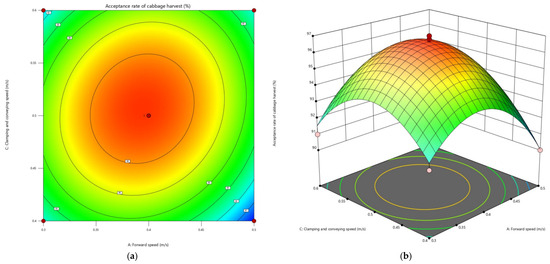
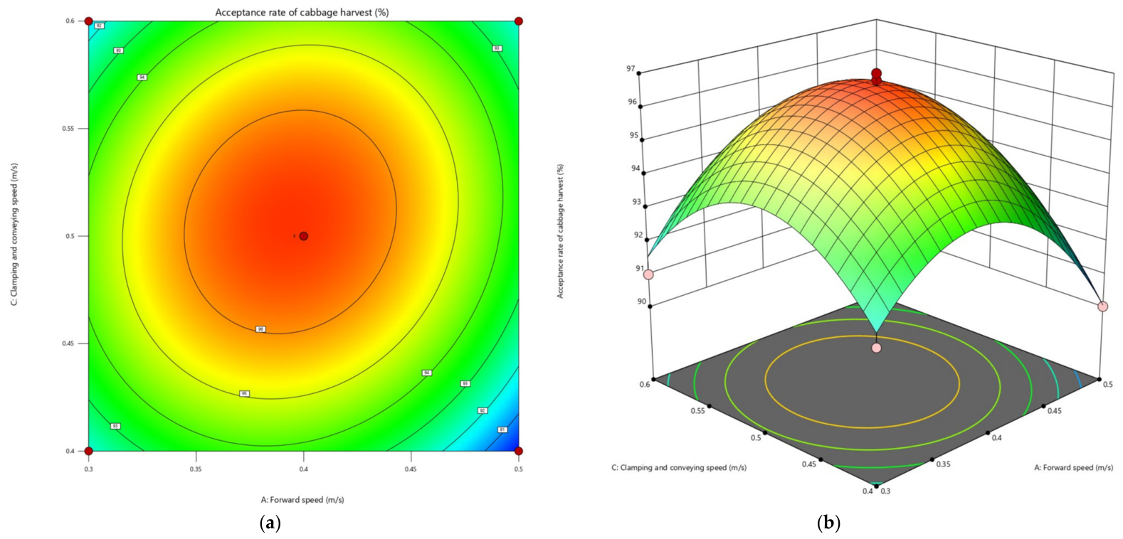
According to the significance analysis of the regression equation in Table 8, the interaction between forward speed () and clamping and conveying speed () has a significant effect on the cabbage harvest qualification rate. To more intuitively analyze this interaction, the pulling roller rotational speed () and cutter rotational speed () were fixed at their zero (central) levels, = 120 r/min and = 300 r/min. Figure 19 presents the response surface and contour plots of the cabbage harvest qualification rate as a function of forward speed and clamping and conveying speed. As shown in the figure, with a constant forward speed, the harvest qualification rate first increases and then decreases as the clamping and conveying speed increases. This is because, when the horizontal component of the clamping and conveying speed is lower than the forward speed, cabbages tend to accumulate at the end of the pulling rollers. During feeding into the clamping and conveying device, they are pushed by the crop guiding roller blades, causing changes in cabbage orientation and resulting in inaccurate or oblique root cuts, which reduces the harvest qualification rate. As the clamping and conveying speed increases, the congestion decreases, and the harvest qualification rate rises. However, further increases in clamping and conveying speed shorten the time the cutter acts on the cabbage roots (with cutter speed held constant), leading to incomplete root cutting and oblique cuts, and the harvest qualification rate declines. Similarly, as the forward speed increases, the harvest qualification rate first rises and then falls. At excessively high forward speeds, the overall harvesting efficiency is high but the harvest qualification rate is low; at excessively low forward speeds, both efficiency and qualification rate are low. The harvest qualification rate is highest when the forward speed is 0.35–0.45 m/s and the clamping and conveying speed is 0.45–0.55 m/s.
Figure 19.
Effects of forward speed and clamping and conveying speed on cabbage harvest qualification rate: (a). Contour plot; (b). Surface plot.
3.3.4. Optimization of the Working Parameters of the Cabbage Harvester
Taking the maximum cabbage harvest qualification rate as the optimization objective, the parameter ranges were set as follows: forward speed 0.3–0.5 m/s, pulling roller rotational speed 80–160 r/min, clamping and conveying speed 0.4–0.6 m/s, and cutter rotational speed 250–350 r/min. The constraint condition for the cabbage harvest qualification rate was set to 90–100%, and the optimization objective function was defined as follows:
where is taken as the optimization objective function, with the constraint range set from 90% to 100%.
The objective function was optimized using Design-Expert 13. The optimization results indicate that when the forward speed is 0.39 m/s, the pulling roller rotational speed is 114.07 r/min, the clamping and conveying speed is 0.51 m/s, and the cutter rotational speed is 337.65 r/min, the maximum theoretical cabbage harvest qualification rate reaches 96.78%.
3.4. Field Performance Validation Experiment
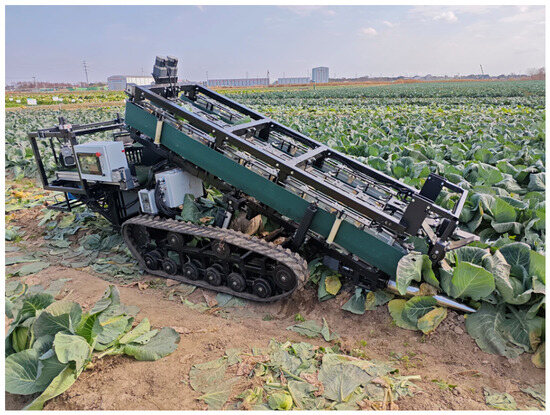
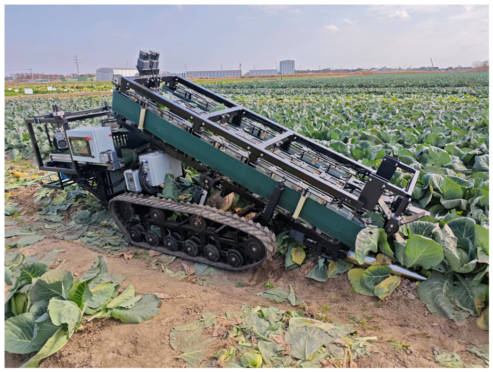
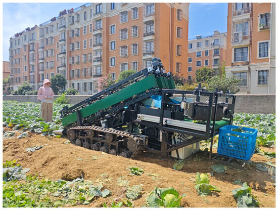
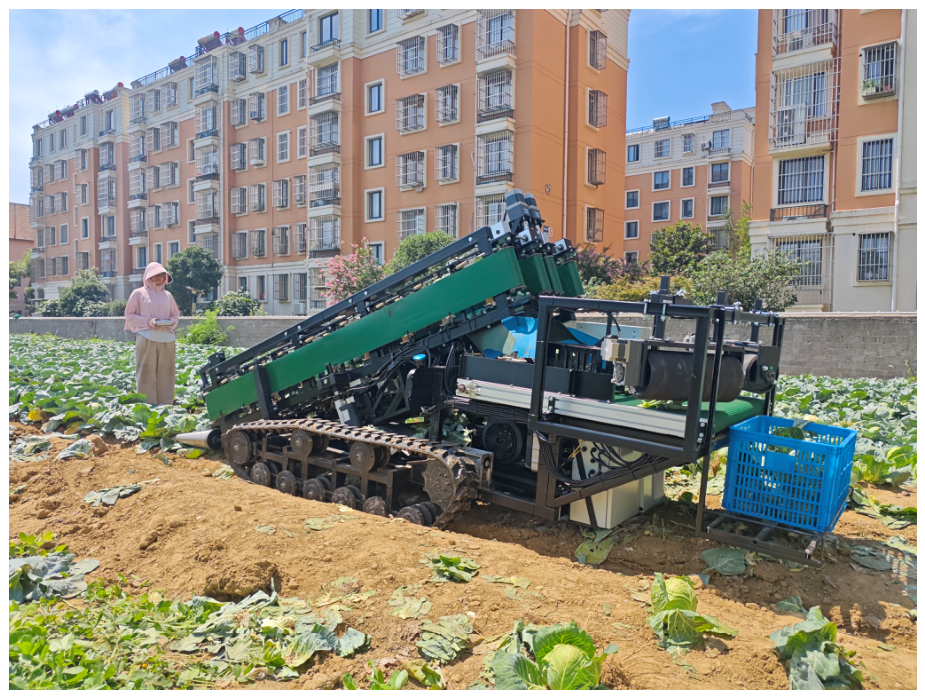
Based on the parameter optimization results of the key components of the crawler-type self-propelled double-row cabbage harvester, the optimal parameter combination was obtained as follows: forward speed 0.39 m/s, pulling roller rotational speed 114.07 r/min, clamping and conveying speed 0.51 m/s, and cutter rotational speed 337.65 r/min, under which the maximum theoretical cabbage harvest qualification rate was 96.78%. Considering practical operating conditions, the optimal parameters were rounded as follows: forward speed 0.4 m/s, pulling roller rotational speed 114 r/min, clamping and conveying speed 0.51 m/s, and cutter rotational speed 338 r/min. When the clamping and conveying speed was 0.51 m/s, the rotational speed of the clamping-ball driving pulley was rounded to 139 r/min, and the rotational speed of the clamping-root driving pulley was rounded to 155 r/min. Five field harvesting performance validation tests were conducted. In each test, 100 consecutive cabbages were selected, and the numbers of cabbages meeting the harvesting qualification and leaf-stripping qualification standards were recorded. The harvest qualification rate and leaf-stripping qualification rate were compared with the maximum theoretical harvest qualification rate obtained from Design-Expert 13, in order to further verify the accuracy of the optimized parameter combination and the field harvesting performance. The field test site is shown in Figure 20.
Figure 20.
Field performance validation experiment site photos.
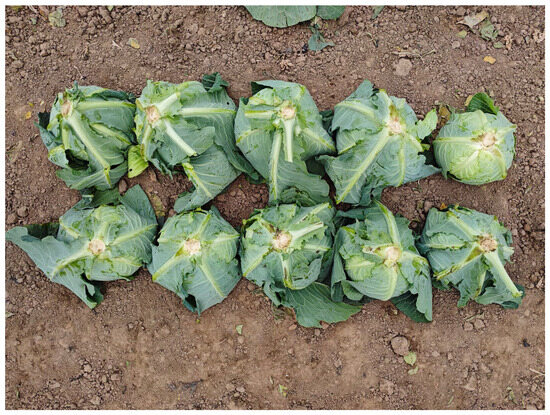
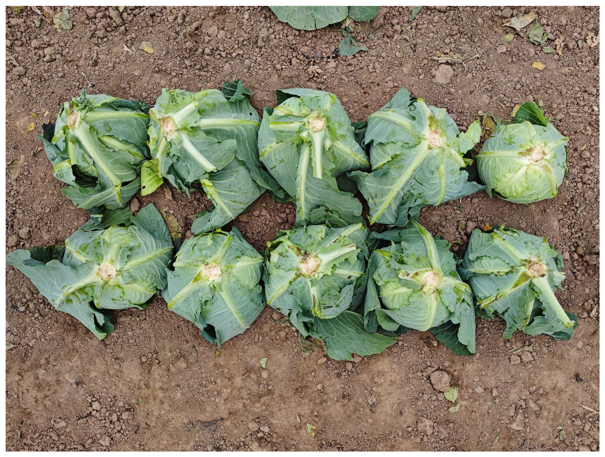
The experimental results are presented in Table 9, in which the number of damaged cabbages includes cabbages damaged by compression, friction, and cutting. Figure 21 shows the cabbages harvested by the crawler-type self-propelled double-row cabbage harvester.
Table 9.
Results of the field performance validation experiment.
Figure 21.
Cabbages harvested by the crawler-type self-propelled double-row cabbage harvester.
The results of the field harvesting performance validation tests indicate that, under the operating conditions of forward speed 0.4 m/s, pulling roller rotational speed 114 r/min, clamping and conveying speed 0.51 m/s, and cutter rotational speed 338 r/min, the average harvest qualification rate reached 96.4%, and the average damage rate was 3.6%. These results are close to the maximum theoretical harvest qualification rate of 96.78% predicted by the optimization model, demonstrating good field harvesting performance of the harvester.
To evaluate the adaptability of the crawler-type self-propelled double-row cabbage harvester to other cabbage varieties, harvesting experiments were conducted on the round-headed cabbage variety “Dianfeng 60”(Jiangsu Academy of Agricultural Sciences, Nanjing, China), as illustrated in Figure 22. During the experiments, the profiling device ensured that the pulling device maintained close contact with the ground surface, enhancing the harvester’s adaptability to variations in ridge surfaces and effectively preventing harvesting failures and mechanical damage to the cabbage. The pulling device with adjustable spacing and angle demonstrated a good gathering effect on misaligned cabbages, reducing the requirement for row straightness and lowering the labor intensity associated with manual alignment. The clamping and conveying device maintained stable cabbage posture during transportation and prevented compressive damage, thereby improving the accuracy of the root cutting position and reducing the cutting damage rate. The experimental results indicated a cabbage harvest qualification rate of 95.6%, confirming that the crawler-type self-propelled double-row cabbage harvester also exhibits good adaptability to other cabbage varieties.
Figure 22.
Harvesting process of cabbage “Dianfeng 60”.
4. Discussion
This study addresses the problems of low efficiency and high damage rate in mechanized cabbage harvesting by designing a crawler-type self-propelled double-row cabbage harvester. The effects of forward speed, pulling roller rotational speed, clamping and conveying speed, and cutter rotational speed on the cabbage harvest qualification rate were analyzed through single-factor experiments and response surface methodology optimization. The results indicated that the factors influenced the harvest qualification rate in the following order: forward speed > clamping and conveying speed > pulling roller rotational speed > cutter rotational speed. The RSM optimization identified the optimal operating parameters as forward speed 0.39 m/s, pulling roller rotational speed 114.07 r/min, clamping and conveying speed 0.51 m/s, and cutter rotational speed 337.65 r/min, corresponding to a theoretical harvest qualification rate of 96.78%. Field validation tests demonstrated that, under practical operating parameters of 0.4 m/s, 114 r/min, 0.51 m/s, and 338 r/min, the average harvest qualification rate reached 96.4%, and the average damage rate was 3.6%, confirming the reliability of the model predictions.
The key technologies of the cabbage harvester are concentrated on the pulling device, conveying device, and root-cutting device [13,14]. Previous studies have shown that variations in cabbage orientation and unstable conveying can reduce root-cutting accuracy, thereby increasing damage rates [39,40]. To address this, the harvester employs a dual clamping structure for both the cabbage head and roots, maintaining stable cabbage orientation during conveying and improving root-cutting precision. To ensure stable clamping while minimizing pressure and preventing compression damage, dynamic analyses were conducted to calculate the minimum clamping force applied by the belt. To enhance the adaptability of the cabbage harvester to different cabbage varieties and complex field planting conditions, a spacing- and angle-adjustable pulling device was designed, improving its adaptability to cabbages of varying diameters and reducing the requirement for straight planting rows. In addition, a profiling device was incorporated to ensure that, during harvesting, the pulling device remains in close contact with the soil surface, thereby enhancing the harvester’s ability to follow uneven ridge surfaces. This design effectively prevents harvesting failures and minimizes damage to cabbages caused by the pulling device. Additionally, coordinated optimization of key operating parameters demonstrated that the harvester achieves high operational efficiency while maintaining a low damage rate, illustrating the effectiveness of combining structural optimization with operational parameter optimization to improve harvesting quality.
Despite these advances, several limitations remain. First, the field trials were conducted in a single location with one cabbage variety, and their applicability under different soil conditions, cabbage varieties, or planting patterns requires further verification. Second, the study primarily focused on mechanical design and parameter optimization, with limited consideration of complex field conditions such as ridge uniformity. Third, long-term operational stability and reliability of the harvester require further testing.
Future research should include field trials across different regions, cabbage varieties, and planting patterns to evaluate adaptability under complex field conditions. The introduction of sensors and automatic control systems could enable real-time adjustment of key component parameters, improving operational stability. Furthermore, variations in cabbage pulling force and root-cutting force across varieties, planting patterns, and soil types may impose new requirements on harvester design. Therefore, future studies should explore adaptive parameter optimization, machine vision, and intelligent control technologies to achieve higher levels of automation and smart operation in mechanized cabbage harvesting.
Furthermore, to address the issue of cabbage accumulation and damage caused by the mismatch between forward speed and clamping-conveying speed identified in the single-factor experiments, future research should focus on establishing a cooperative control model between the power chassis and the harvesting implements. In complex field environments, the actual forward speed of the tracked chassis often fluctuates dynamically due to soil conditions and slip rates. To mitigate this, a bottom-layer coordinated control system based on an embedded platform can be developed. By utilizing the RS485/CAN communication protocol to establish real-time data exchange between the main control unit of the tractor/chassis and the harvesting implement controller, the system can dynamically acquire the actual ground speed telemetry. Using this real-time speed data, closed-loop control algorithms can be applied to dynamically adjust the rotational speed of the clamping and conveying motors, ensuring constant dynamic synchronization. This coordinated control strategy will effectively eliminate mechanical damage caused by transient speed mismatches, laying a solid hardware and software foundation for the intelligent operation of future unmanned cabbage harvesting equipment.
5. Conclusions
(1) Mechanical property tests for cabbage harvesting were conducted. The transverse diameter of the cabbage heads was (180.2 ± 26.48) mm, the longitudinal diameter was (114.95 ± 19.08) mm, the plant spread was (625.05 ± 115.28) mm, the plant height was (171.41 ± 28.82) mm, the ground clearance of the lower leaf was (28.19 ± 17.04) mm, and the length of the main root below the soil surface was (66.55 ± 24.04) mm. The total mass (including roots and outer leaves) was (2.37 ± 0.6) kg. The maximum pulling force of cabbage was 327.77 N, the minimum was 157.78 N, and the average value was 233.58 N. When root cutting was performed at 20 mm below the upper leaf attachment position, the average specific cutting force was 9.93 N/cm2.
(2) A pulling device with adjustable spacing ranging from 50 to 90 mm was developed to enhance the harvester’s adaptability to different cabbage varieties and diameters, reducing the requirement for perfectly straight planting rows. A dual clamping and conveying structure, consisting of a clamping-ball and clamping-root mechanism, was implemented to maintain cabbage orientation during transport, thereby improving the accuracy of root-cutting positions. Through dynamic analysis, the spring parameters of the clamping-ball swing wheel assembly were determined: material diameter 2 mm, mean coil diameter 20 mm, and 18 effective coils. The maximum clamping force on the cabbage during conveying was calculated as 38.71 N, well below the critical threshold for compression damage. A profiling device was also designed, allowing the cutter table to adjust laterally within a range of ±9°, accommodating a maximum ridge height variation of ±63.4 mm, which effectively reduces harvesting losses.
(3) Through single-factor experiments and RSM optimization, the effects of forward speed, pulling roller rotational speed, clamping and conveying speed, and cutter rotational speed on the cabbage harvest qualification rate were analyzed, and a quadratic regression model was established. The results showed that the influence of each factor on the harvest qualification rate followed the order: forward speed > clamping and conveying speed > pulling roller rotational speed > cutter rotational speed. Based on RSM optimization, the optimal operating parameters of the harvester were determined as forward speed 0.39 m/s, pulling roller rotational speed 114.07 r/min, clamping and conveying speed 0.51 m/s, and cutter rotational speed 337.65 r/min, corresponding to a theoretical maximum harvest qualification rate of 96.78%.
(4) Field validation tests indicated that, when the harvester operated at forward speed 0.4 m/s, pulling roller rotational speed 114 r/min, clamping and conveying speed 0.51 m/s, and cutter rotational speed 338 r/min, the average harvest qualification rate reached 96.4%, and the average damage rate was 3.6%. These results closely matched the theoretical optimization, demonstrating that the designed harvester possesses excellent operational performance and practical application potential.
Although the experimental results demonstrate that the developed cabbage harvester achieves a relatively high cabbage harvest qualification rate and a low damage rate, its levels of automation and intelligence remain limited. In future work, navigation and positioning technologies can be introduced into the harvesting process to enable unmanned cabbage harvesting. In addition, intelligent control technologies can be applied to achieve precise control of key components, thereby enhancing the functionality and operability of the cabbage harvester and further reducing the damage rate.
Author Contributions
Conceptualization, Q.Z. and Z.Z.; methodology, Z.Z. and Q.Z.; software, Z.Z. and Y.F.; validation, Q.D. and H.P.; investigation, Q.Z., Q.D., H.P., S.Z. and Y.F.; resources, Z.Z.; data curation, Q.Z. and Q.D.; writing—original draft preparation, Q.Z.; writing—review and editing, Z.Z. and Q.Z.; visualization, Q.Z.; supervision, Z.Z. and H.M.; project administration, Z.Z.; funding acquisition, Z.Z. All authors have read and agreed to the published version of the manuscript.
Funding
This work was supported by the earmarked fund for China Agriculture Research System (CARS-23-D03) and the Priority Academic Program Development of Jiangsu Higher Education Institutions (Jiangsu Education Department, Grant No. PAPD-2023-87).
Data Availability Statement
The data presented in this study are available on request from the corresponding author.
Conflicts of Interest
The authors declare no conflicts of interest.
References
- Yang, J.; Du, Y.; Fang, X.; Zhou, C. Design and experimental study of cabbage picking and conveying device. J. Chin. Agric. Mech. 2024, 45, 32–36. [Google Scholar] [CrossRef]
- Tong, W.; Zhang, J.; Song, Z.; Cao, G.; Jin, Y.; Ning, X. Research status and development trend of cabbage mechanical harvesting equipment and technology. J. Chin. Agric. Mech. 2024, 45, 322–329. [Google Scholar] [CrossRef]
- Zhou, M.; Shan, Y.; Xue, X.; Yin, D. Theoretical analysis and development of a mechanism with punching device for transplanting potted vegetable seedlings. Int. J. Agric. Biol. Eng. 2020, 13, 85–92. [Google Scholar] [CrossRef] [Scilit]
- Yue, R.; Yao, M.; Zhang, T.; Shi, J.; Zhou, J.; Hu, J. Design and Experiment of Dual-Row Seedling Pick-Up Device for High-Speed Automatic Transplanting Machine. Agriculture 2024, 14, 942. [Google Scholar] [CrossRef] [Scilit]
- Jia, W.; Tai, K.; Wang, X.; Dong, X.; Ou, M. Design and Simulation of Intra-Row Obstacle Avoidance Shovel-Type Weeding Machine in Orchard. Agriculture 2024, 14, 1124. [Google Scholar] [CrossRef] [Scilit]
- Zheng, S.; Zhao, X.; Fu, H.; Tan, H.; Zhai, C.; Chen, L. Design and Experimental Evaluation of a Smart Intra-Row Weed Control System for Open-Field Cabbage. Agronomy 2025, 15, 112. [Google Scholar] [CrossRef] [Scilit]
- Mori, G.; Paternò, F.; Santoro, C. Design and Development of Multidevice User Interfaces through Multiple Logical Descriptions. IEEE Trans. Softw. Eng. 2004, 30, 507–520. [Google Scholar] [CrossRef]
- Ji, W.; Qian, Z.; Xu, B.; Tang, W.; Li, J.; Zhao, D. Grasping damage analysis of apple by end-effector in harvesting robot. J. Food Process Eng. 2017, 40, e12589.12581. [Google Scholar] [CrossRef] [Scilit]
- Ji, W.; He, G.; Xu, B.; Zhang, H.; Yu, X. A New Picking Pattern of a Flexible Three-Fingered End-Effector for Apple Harvesting Robot. Agriculture 2024, 14, 102. [Google Scholar] [CrossRef] [Scilit]
- Lei, X.; Liu, J.; Jiang, H.; Xu, B.; Jin, Y.; Gao, J. Design and Testing of a Four-Arm Multi-Joint Apple Harvesting Robot Based on Singularity Analysis. Agronomy 2025, 15, 1446. [Google Scholar] [CrossRef] [Scilit]
- Cao, Y.; Yu, Y.; Tang, Z.; Zhao, Y.; Gu, X.; Liu, S.; Chen, S. Multi-Tooth Cutting Method and Bionic Cutter Design for Broccoli Xylem (Brassica oleracea L. var. Italica Plenck). Agriculture 2023, 13, 1267. [Google Scholar] [CrossRef] [Scilit]
- Yang, G.; Xiao, H.; Zhang, J.; Jin, Y.; Jiang, Q.; Yao, S. Design and experiment of double disc root cutting device of cabbage. J. Chin. Agric. Mech. 2020, 41, 83–88. [Google Scholar] [CrossRef]
- Wang, W.; Lv, X.; Wang, S.; Lu, D.; Yi, Z. Current status and development of stem and leaf vegetable mechanized harvesting technology. J. China Agric. Univ. 2021, 26, 117–127. [Google Scholar]
- Zou, L.; Liu, X.; Yuan, J.; Dong, X. Research progress in mechanized harvesting technology and equipment of leafy vegetables. J. Chin. Agric. Mech. 2022, 43, 15–23. [Google Scholar] [CrossRef]
- Zhang, J.; Li, Y.; Tang, J.; Tong, W.; Song, Z.; Cao, G. Design and Experiment of Vertical Clamping Combine Harvester for Cabbage. Trans. Chin. Soc. Agric. Mach. 2026, 57, 70–80. [Google Scholar]
- Zhang, J.; Wang, J.; Du, D.; Long, S.; Wang, Y.; You, X. Development and experiment of self-propelled cabbage harvester. Editor. Off. Trans. Chin. Soc. Agric. Eng. 2015, 31, 16–23. [Google Scholar]
- Yao, S.; Zhang, J.; Xiao, H.; Jin, Y. Experiment and Design of 4GYZ—1200 Cabbage Harvester. J. Agric. Mech. Res. 2021, 43, 52–57. [Google Scholar] [CrossRef]
- Song, H.S.; Whon, T.W.; Kim, J.; Lee, S.H.; Kim, J.Y.; Kim, Y.B.; Choi, H.-J.; Rhee, J.-K.; Roh, S.W. Microbial niches in raw ingredients determine microbial community assembly during kimchi fermentation. Food Chem. 2020, 318, 126481. [Google Scholar] [CrossRef] [Scilit] [PubMed]
- Wang, F.E.; Guo, W.; Cao, X.; Han, Z.; Wei, H. Study on cabbage production situation and mechanized harvesting technology. Chin. Agric. Mech. 2009, 3, 79–82+89. [Google Scholar] [CrossRef] [Scilit]
- Li, X.; Wang, F.E.; Guo, W.; Gong, Z.; Zhang, J. Influencing factor analysis of cabbage root cutting force based on orthogonal test. Trans. Chin. Soc. Agric. Eng. (Trans. CSAE) 2013, 29, 42–48. [Google Scholar]
- Pan, T.; Shangguan, X. Development of Small-Sized Cabbage Harvesting Equipment for Smallholder Farmers. Int. Core J. Eng. 2025, 11, 275–282. [Google Scholar] [CrossRef]
- Tong, W.; Zhang, J.; Cao, G.; Song, Z.; Jin, Y.; Song, X. Design and test of hand-held cabbage harvester. J. Chin. Agric. Mech. 2023, 44, 30–36. [Google Scholar] [CrossRef]
- Zhou, C.; Chen, H.; Li, L. Development of Parametric Design System for Subsoiler Based on CATIA. J. Agric. Mech. Res. 2013, 35, 134–138. [Google Scholar] [CrossRef]
- Yan, K.; Yao, S.; Huang, Y.; Zhao, Z. Study on Pulling Dynamic Characteristics of White Radish and the Optimal Design of a Harvesting Device. Agriculture 2023, 13, 942. [Google Scholar] [CrossRef] [Scilit]
- Cao, Y.; Tang, Z.; Lu, D.; Lin, S. Performance Test of Artificial Defoliating Broccoli Conveyor Line and Analysis of Defoliating Broccoli Inflorescences. Agronomy 2024, 14, 1925. [Google Scholar] [CrossRef] [Scilit]
- Sarkar, P.; Raheman, H. A Comprehensive Review of Mechanized Cabbage Harvesting Systems and Its Present Status in India. J. Inst. Eng. (India) Ser. A 2021, 102, 861–869. [Google Scholar] [CrossRef] [Scilit]
- Sarkar, P.; Raheman, H. Design, structural analysis and development of a walk-behind type electric cabbage harvester. Int. J. Sustain. Eng. 2024, 17, 806–828. [Google Scholar] [CrossRef] [Scilit]
- Sarkar, P.; Raheman, H. Development and performance evaluation of an electric cabbage harvester with a precise cabbage pushing mechanism. Smart Agric. Technol. 2024, 8, 100465. [Google Scholar] [CrossRef] [Scilit]
- Sarkar, P.; Raheman, H. Development of an electric cabbage harvester: An eco-friendly solution for mechanical harvesting of cabbage. Clean Technol. Environ. Policy 2024, 27, 141–155. [Google Scholar] [CrossRef] [Scilit]
- Sarkar, P.; Raheman, H.; Sahoo, A.U. Field performance evaluation and economic analysis of an electric cabbage harvester suitable for small farms. Discov. Agric. 2025, 3, 15. [Google Scholar] [CrossRef] [Scilit]
- Alatyrev, A.S.; Emelyanov, N.A.; Kruchinkina, I.S.; Alatyrev, S.S. Development and research of a new separating device for a cabbage harvester. Tract. Agric. Mach. 2023, 90, 25–31. [Google Scholar] [CrossRef] [Scilit]
- Alatyrev, A.S.; Emelyanov, N.A.; Nikitin, V.S.; Kruchinkina, I.S.; Alatyrev, S.S. The combine harvester for cabbage harvesting in small-scale farms. Tract. Agric. Mach. 2024, 91, 155–165. [Google Scholar] [CrossRef] [Scilit]
- Alatyrev, A.S.; Alatyrev, S.S.; Kruchinkina, I.S. Theoretical study of the working process of a multivariate cabbage harvester. Tract. Agric. Mach. 2024, 91, 485–492. [Google Scholar] [CrossRef] [Scilit]
- Alatyrev, A.S.; Kruchinkina, I.S.; Alatyrev, S.S.; Nikitin, V.S. The technology of cabbage harvesting with the use of the multiple-option harvester and the economic assessment of it. Tract. Agric. Mach. 2023, 90, 487–498. [Google Scholar] [CrossRef] [Scilit]
- Hou, A.; Tsuruta, H.; Mc Creary, M.A.; Hosen, Y. Effect of urea placement on the time-depth profiles of NO, N2O and mineral nitrogen concentrations in an Andisol during a Chinese cabbage growing season. Soil Sci. Plant Nutr. 2010, 56, 861–869. [Google Scholar] [CrossRef] [Scilit]
- Yuan, L.; Tang, Z.; Liu, S.; Wang, T.; Ding, Z. Design for Copying Grouser and Bionic Convex Hull Patterns on Track Surfaces of Crawler Combine Harvesters. Agriculture 2024, 14, 1079. [Google Scholar] [CrossRef] [Scilit]
- GB/Z 26582-2011; Production Technical Practice for Cabbage. China National GB Standard Research: Shenzhen, China, 2011.
- NY/T 4073-2022; Technical Code of Practice for Mechanized Production of Cabbage. Ministry of Agriculture and Rural Affairs of the People’s Republic of China: Beijing, China, 2022.
- Li, T.; Meng, Z.; Ding, H.; Hou, J.; Shi, G.; Zhou, K. Mechanical analysis and parameter optimization of cabbage root cutting operation. Trans. Chin. Soc. Agric. Eng. (Trans. CSAE) 2020, 36, 63–72. [Google Scholar]
- Zhao, Q.; Wang, J.; Wang, Z.; Tian, T.; Zhao, Y.; Cui, L.; Hong, M. Application of Clamping Conveyer Technology in Vegetable Harvesting Machine. Agric. Eng. 2020, 10, 8–11. [Google Scholar]

Disclaimer/Publisher’s Note: The statements, opinions and data contained in all publications are solely those of the individual author(s) and contributor(s) and not of MDPI and/or the editor(s). MDPI and/or the editor(s) disclaim responsibility for any injury to people or property resulting from any ideas, methods, instructions or products referred to in the content. |
© 2026 by the authors. Licensee MDPI, Basel, Switzerland. This article is an open access article distributed under the terms and conditions of the Creative Commons Attribution (CC BY) license.