


Abstract
The SORGENTINA-RF (SRF) project, dedicated to the production of medical radioisotopes, requires a tritium facility to process the exhaust gas of the vacuum chamber, containing a percentage of impurities of around 1%, and to allow for the recirculation of the purified hydrogen isotopes. Inside such a tritium facility, the Pd-Ag Permeator System is conceived to operate in a closed configuration (filter mode), where impurities accumulate inside the membrane. A characterisation of this transient behaviour is required to support the design and safety assessment of the SRF Permeator System. To this end, two numerical models were developed. A Python-based implementation was first introduced to investigate the physical mechanisms governing the hydrogen permeation process. Then, the same mathematical formulations were implemented in a custom component in Simscape, incorporating the control logic in a single-membrane configuration. The models were validated against experimental data collected at the Hydrogen Permeation (HyPe) facility of the ENEA Frascati Laboratories, showing good agreement with average relative errors below 9%. The models were applied to assess system behaviour under the operating conditions of the SRF Facility, considering a H2 reference case. A multi-membrane configuration was developed to achieve continuous operation at the system level by activating the membranes in sequence. The effect of membrane length and number of units on system performance was investigated. A configuration of seven membranes 0.12 m in length was found to achieve continuous operation at the system level, with a mean managed flow rate of approximately 1.02 × 10⁻⁵ mol·s−1, satisfying the requirements of the SRF Tritium Facility. A sensitivity analysis on hydrogen permeability was carried out by varying this parameter by ±50% to account for the isotopic difference between hydrogen and D/T operation. Considering higher permeability, the system remained consistent with the reference case. In the case of lower permeability, a membrane length of approximately 0.22 m was required to meet the same performance of the reference H2 configuration. The residual tritium to be discharged during the emptying phase of the membranes was also quantified, corresponding to a total release of approximately 5.60 × 10⁻³ g·day−1 over 24 h of continuous operation, which increases to 1.06 × 10⁻² g·day−1 in the case of lower permeability. These results establish minimum design criteria for continuous filter-mode operation and provide a preliminary estimation of tritium release under the operating conditions considered, which may serve as input for future analyses of tritium inventories and the associated safety aspects of tritium management systems.
1. Introduction
The SORGENTINA-RF (SRF) project is devoted to the development of a medium-intensity 14 MeV fusion neutron source dedicated to the production of radioisotopes, especially 99Mo as a precursor of 99mTc, used in nuclear medicine diagnostic procedures [1]. The neutron source relies on a deuterium–tritium ion accelerator and a rotating target covered with a titanium layer, on which D-T ions will be implanted. The impinging ion beam particle will be able to start fusion reactions which in turn will produce the source neutrons, used to irradiate natural molybdenum, triggering the 100Mo(n,2n)99Mo reaction. More details about the ion beam and the neutron source can be found in [2,3].
Previous analyses on the operation of the SRF Facility identified a requirement of about 1.12 g·day−1 of tritium to produce the nominal ion beam under steady-state conditions (considering an efficiency of the ion source of 100%) [2], which correspond to a value of about 30 k€ [4]. Inside the vacuum chamber, only a small fraction of the inserted fuel is consumed via fusion reactions; so, the exhaust gas coming from the vacuum chamber is composed mainly of deuterium and tritium plus some impurities generated during the operation of the machine, such as helium, argon, oxygen, titanium and hydrogen isotope compounds. Therefore, a tritium recovery system becomes necessary to recycle as much tritium as possible and thus ensure the economic feasibility of the project. A first filtering system is devoted to cleaning the exhaust stream from particulate (e.g., TiD and TiT); then the hydrogenic species are separated by using a Pd-Ag permeator tube.
The use of Pd-based membranes for hydrogen purification purposes has been widely investigated in hydrogen production, membrane reactor and gas separation applications [5,6,7,8], with a significant role in nuclear fusion fuel-cycle systems [9,10,11,12,13,14]. The reason is that these membranes have exclusive selectivity and high permeability to hydrogen isotopes with respect to other metal alloys, ensuring unique separation performance and production of ultra-high-purity hydrogen [15]. The gas stream to be purified enters the membrane tube, and hydrogen species can permeate thanks to the partial-pressure difference between the two sides of the membrane. The particles that do not permeate form the retentate stream.
Pd-based membranes can be classified into two categories: dense self-supported and thin supported (composite) membranes. Thin supported membranes can achieve significantly higher permeation fluxes due to their reduced thickness but are often characterised by lower durability and susceptibility to pinhole formation, thus reducing hydrogen selectivity [16]. Furthermore, the production of reliable ultrathin membranes is technologically challenging and requires complex fabrication procedures. On the other hand, dense self-supported membranes exhibit lower hydrogen permeance owing to their larger thickness but can provide infinite hydrogen selectivity, good chemical stability and high mechanical robustness, and can be produced with a simpler and more mature manufacturing procedure. These characteristics represent key requirements for near/mid-term operation in tritium applications. In this context, technology readiness and commercial availability are additional selection criteria, making self-supported membranes an attractive and reliable solution for tritium handling systems [17].
Usually, the most common operation mode for this type of membranes is working in continuous flow, meaning that the retentate continuously leaves the permeator through a dedicated line [18,19,20]. However, this configuration requires additional downstream processes to recover residual tritium from the retentate stream. In contrast, filter-mode operation retains the gas within the permeator until most of the hydrogen isotopes have permeated through the membrane, thus increasing the overall recovery efficiency and reducing the tritium content in the retentate stream. These benefits are achieved at the expense of a more complex operation logic, forcing multiple membranes to work in parallel to ensure continuous operation.
Since in the SRF Permeator System the exhaust gas is supposed to have a much smaller flow rate and impurity content compared with fusion systems for energy production [21], filter-mode operation has been selected as a viable alternative to continuous-flow configuration, with the objectives of simplifying the overall system layout and maximising tritium recovery. This choice also represents an opportunity to explore an operational mode that could enable a future comparison with continuous-flow operation.
For this scope, a transient numerical model is required to analyse the behaviour of a permeator system working in filter mode. While numerical models have been developed to describe hydrogen permeation in continuous-flow configurations [18,22,23,24,25], these mainly address steady-state operation and do not capture the time-dependent behaviour characteristic of filter-mode operation, which, to the authors’ knowledge, has not been previously modelled.
In this context, the present work has the scope to develop and validate a transient numerical model for the Pd-Ag membrane for the Tritium Facility of SRF operating in filter mode, providing a tool not previously available for this configuration. More specifically, it aims at demonstrating the feasibility of continuous operation through a multi-membrane sequential activation scheme and conducting a preliminary parametric analysis of the key design parameters (e.g., membrane length and number of Permeator Units). Additionally, the residual tritium in the membrane lumen is quantified, providing an estimation of its losses during the discharge phase. Taken together, these results are intended to provide useful guidelines to support future design activities for the SORGENTINA-RF project.
This paper is organised as follows: Section 2 provides an overview of the SRF Tritium Facility with the preliminary information of the operating conditions. Section 3 is devoted to the description of the Permeator Unit (PU) and of the developed model: a Python-based model is first introduced to investigate the fundamental mechanisms governing the permeation process, followed by a Simscape implementation which incorporates the associated control logic. Section 4 addresses the validation of the model against experimental data collected during a campaign conducted at the Hydrogen Permeation (HyPe) facility located at the ENEA Frascati Laboratories. Section 5 reports the application of the model to the SRF Tritium Facility, with the evaluation of the effect of membrane geometry on the inlet flow rate, aiming at identifying a solution compatible with the requirements of the project. A sensitivity analysis on permeability and a quantitative assessment of the tritium release occurring during the discharge phase are also performed as supporting results. Finally, Section 6 summarises the main conclusions of this work and outlines the future perspectives foreseen for the project.
2. SRF Tritium Facility
The main purpose of the SRF Tritium Facility is to process the exhaust gas coming from the vacuum chamber, removing the impurities and re-introducing Q2 (Q = D, T) isotopes into the ion chamber. According to the preliminary design and the requirements defined inside the SRF project framework, the system must be able to manage an exhaust gas flow rate of about 0.036 mol·h−1 of D-T from the vacuum chamber. The purified D-T mixture must be stored in dedicated buffer tanks from which the ion beam is fuelled in a stoichiometric ratio of 50:50 within a tolerance of ±5%.
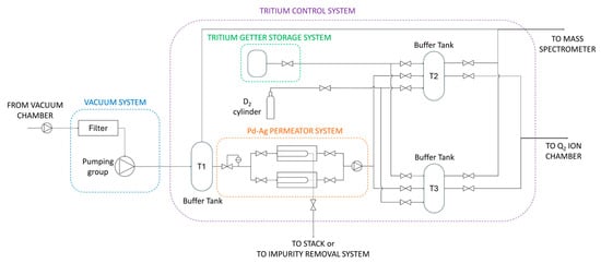
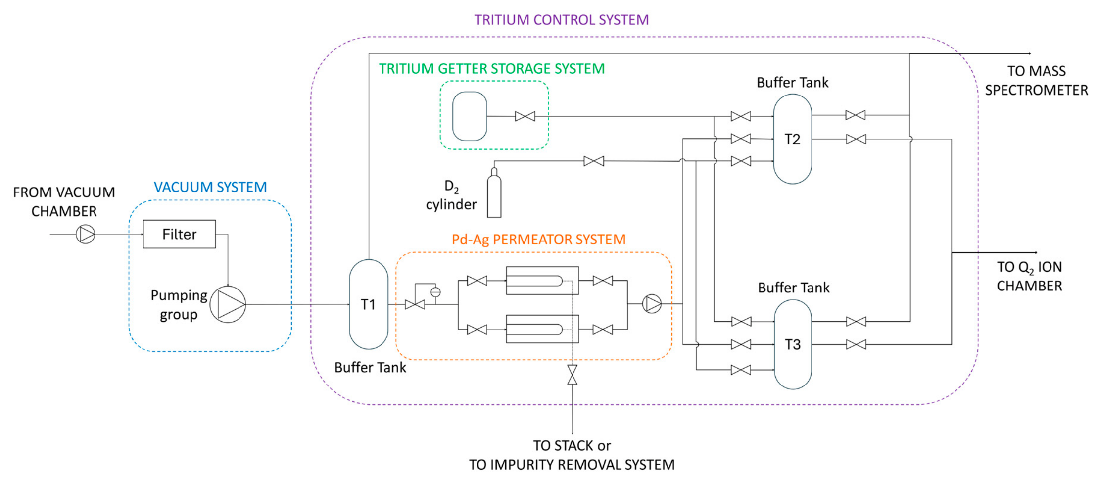
A preliminary layout of the Tritium Facility can be seen in Figure 1, in which the following subsystems can be identified: the Vacuum System and the Tritium Control System, which includes the Pd-Ag Permeator System, the Tritium Getter Storage System, three buffer tanks (Buffer Tanks T1, T2 and T3) and a deuterium cylinder. The main operating conditions of the Tritium Facility are reported in Table 1.
Figure 1.
Preliminary layout for the Tritium Facility of the SRF project.
Table 1.
Operating conditions of SRF Tritium Facility.
The Vacuum System interfaces with the vacuum chamber and the Tritium Control System and consists of a pumping group and a filtering system devoted to the removal of possible solid particles from the mixture flow rate coming from the vacuum chamber. The pumping group drives the Q2 flow rate to Buffer Tank (BT) T1, which has the function of storage before sending it to the Pd-Ag Permeator System. Then, the Q2 stream passes through a pressure-reducing valve and reaches the Pd-Ag Permeator System, in which D-T hydrogen isotopes are separated from impurities. This system is composed of multiple permeating membranes to ensure continuous operation. The purified Q2 flow rate is then pumped to two separated tanks, Buffer Tank T2 and Buffer Tank T3, which are used alternatively: one is filled with the purified flow, while the other is balanced to achieve the required stoichiometric D-T ratio of 50:50. The balancing is performed by means of the Tritium Getter Storage System and a D2 cylinder. In the Tritium Getter Storage System, tritium is stored by means of a getter bed, and its release is controlled by a dedicated heating system. Finally, the Q2 mixture is routed from Buffer Tanks T2 and T3 to the ion source’s chamber. All three storage tanks are provided with additional penetration to send the mixture to a mass spectrometer to control the gas composition.
3. Methodology
3.1. Permeator Unit
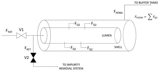
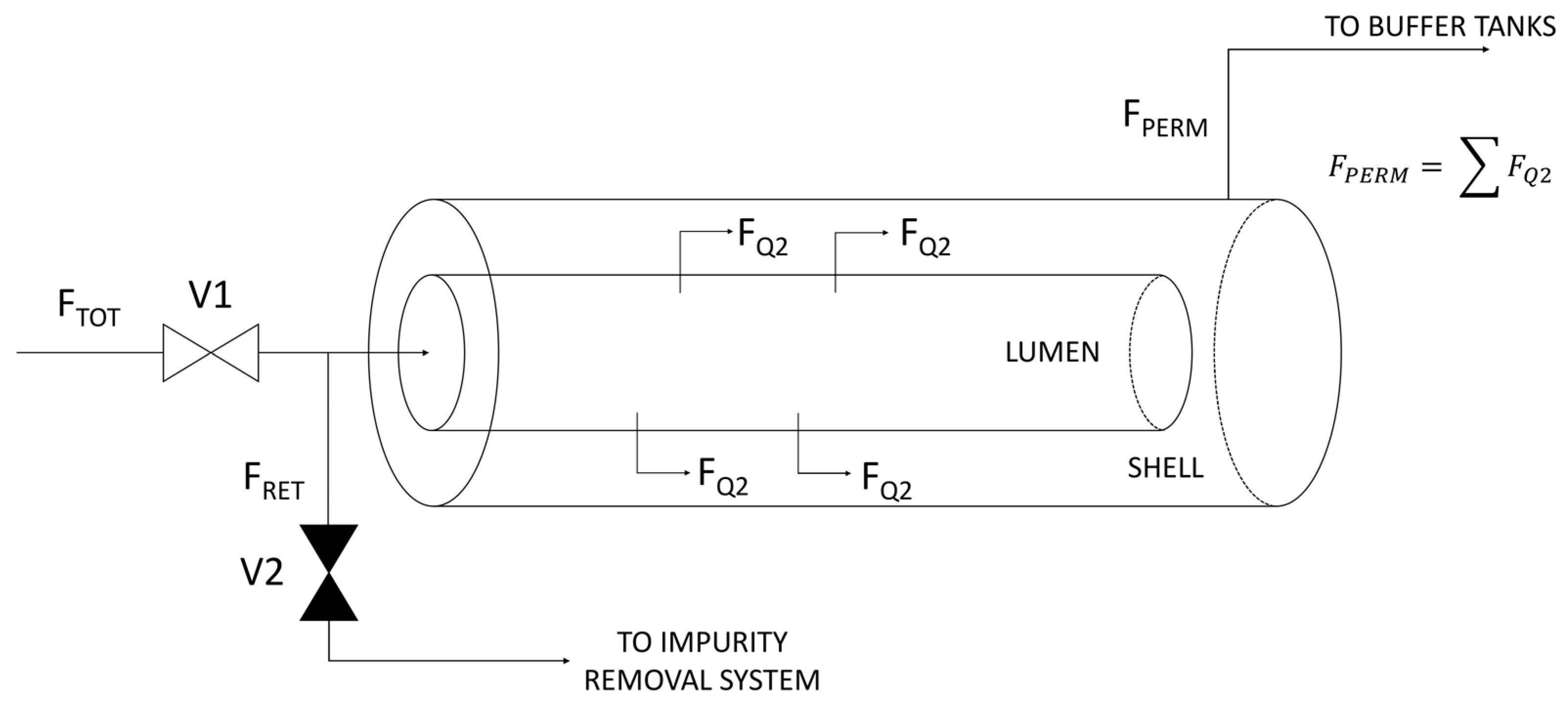
The core of the whole Tritium Facility is the Permeator Unit, which consists of a dense Pd-Ag membrane. According to the scheme of the permeator shown in Figure 2, two areas can be distinguished: the lumen side, which is the internal volume of the membrane, and the shell side, which is the volume between the membrane and the outer containment. The permeation direction foreseen for the filter-mode configuration is lumen to shell: this allows for the minimisation of the tritium inventory inside the Unit. The information about geometry and operating conditions of the Permeator Unit can be found in Table 2. It should be noted that the selected operating conditions should be regarded as a set of boundary conditions imposed by the SRF project, rather than optimised design variables.
Figure 2.
Schematic representation of the Permeator Unit.
Table 2.
Geometry and operating conditions of the Permeator Unit.
The exhaust gas flow rate from the vacuum chamber (FTOT) is at the operating pressure of 200 Pa and enters the lumen through Valve V1. Q2 species start permeating through the membrane and reach the shell side (FQ2), according to the Richardson equation under the condition of a diffusion-limited regime (DLR) [26]:
where J [mol·m−2·s−1] is the permeated flux, P [mol·m−1·s−1·Pa−0.5] is the permeability, δ [m] is the membrane thickness, and pQ2,lumen [Pa] and pQ2,shell [Pa] are the partial pressures of the hydrogen species at the high-pressure (lumen) side and low-pressure (shell) side, respectively.
Hydrogen permeability depends on the temperature through an Arrhenius-type function:
where P0 [mol·m−1·s−1·Pa−0.5] is defined as the pre-exponential permeability coefficient, Ea [J·mol−1] is the activation energy for permeation, T [K] is the temperature and R [J·mol−1·K−1] is the gas constant.
In this regime, the rate-limiting step is the diffusion of hydrogen through the bulk of the membrane, while surface effects can be considered negligible. However, depending on the operating conditions and cleanliness of the membrane surface, the permeation process may be subject to a surface-limited regime (SLR), where the rate-limiting step is the dissociation/recombination of hydrogen at the membrane surface, or to an intermediate regime, where both bulk diffusion and surface effects make a non-negligible contribution to the overall permeation process [26].
The permeating species () are delivered to the Q2 buffer tanks by means of a dedicated pumping system which continuously maintains the pressure in the shell side at 10 Pa, to have the partial-pressure difference between the two sides of the membrane. Valve V2 is kept closed, so impurities that do not permeate accumulate in the lumen and form the retentate. As permeation goes on, the partial pressure of Q2 species decreases, and the partial pressure of impurities increases due to their accumulation in the lumen. This process continues until the Q2 partial pressure reaches the value of the pressure in the shell side: at this point, the driving force for permeation is no longer present, so the process stops, and the lumen must be emptied. Valve V1 is closed, and Valve V2 is opened, so that the retentate (FRET) can leave the permeator.
The model presented in this work aims at evaluating the time in which the membrane is filled by impurities, which represents one of the figures of merit for numerical modelling. In fact, predicting the duration of the filling phase will allow us to design the continuous operation of the Facility, which relies on multiple parallel permeators suitably dimensioned and synchronised to handle the exhaust gas without interruptions. Another important figure of merit is related to the quantity of tritium released during the emptying phase. This value must be minimised and will help to determine if a further tritium recovery system is required after the Pd-Ag Permeator System.
3.2. Model Description
The modelling methodology involves two steps. A Python code (version 3.14.0) was first developed to investigate the permeation physics, describing the transient evolution of partial pressures within a single permeator and providing a basis for the subsequent system-level implementation. The same mathematical formulation was then implemented in a custom Simscape component representing the Permeator Unit. The Simscape model incorporates this component into a complete representation of the Pd-Ag Permeator System (as described in Figure 1), accounting for the dynamic interaction of the Permeator Unit with Buffer Tank T1, the valves and the control subsystems. Simscape (version 24.2, R2024b) is a software program with a predefined set of libraries and features for modelling physical systems in the Simulink® environment (version 24.2, R2024b) [27].
The objective of the Python code is to calculate the filling time of a permeator working in a closed configuration, in which a mixture of permeating and non-permeating species is inserted. For this model, the selected permeating species is hydrogen (H2) in this preliminary phase. This choice is motivated by the wider availability of permeability data for hydrogen in the literature and by the fact that the experimental campaign used for model validation is carried out using hydrogen. Since the SRF Facility will operate with a D/T mixture, the isotopic effect on permeation is a relevant consideration. Heavier hydrogen isotopes show lower permeability through Pd-Ag membranes [22,28,29,30]: considering a D-T ratio of 50:50 at the operating temperature of 673 K, the effective permeability is estimated to be approximately 47% lower with respect to hydrogen. This will potentially affect the operation of the Pd-Ag Permeator System and will be discussed in Section 5.
The code considers a tubular membrane of length Lm [m], external diameter dext [m] and thickness δ [m] as geometrical parameters. Other inputs are the operating temperature of the membrane Top [K], the hydrogen feed and shell pressures pfeed [Pa] and pshell [Pa], the impurity content of the feed gas mixture cimp and the hydrogen permeability through the Pd-Ag membrane PH2 [mol·m−1·s−1·Pa−0.5], calculated through Equation (2). The model considers a single control volume; this approach is in line with the system-level nature of the present work, which focuses on the transient evolution of global quantities, without resolving local transport phenomena. This representation does not account for spatial variations in species concentration along the membrane tube. Consequently, it does not resolve the local variation in partial pressure, which may influence the permeation rate and the gas composition along the permeator. The model is therefore intended to describe the system-level behaviour under the operating conditions considered.
The system of ordinary differential equations (ODEs) is described as follows:
where nH2 [mol] and nimp [mol] are the state variables, i.e., the number of moles of the feed gas species; t [s] is time, FH2,in(t) [mol·s−1] and Fimp(t) [mol·s−1] are the inlet flow rate of hydrogen and impurities species, respectively; and Fperm(t) [mol·s−1] is the permeation flow rate calculated through Equation (1). The numerical integration of the ODE system over time is performed using the solve_ivp solver from the SciPy library [31].
Summing the species balances, the total accumulation equation is obtained:
According to the operating conditions foreseen for the SRF Facility, the lumen pressure is assumed to remain constant during the permeation phase. The feed is supplied by a buffer tank at constant pressure, so the inlet flow rate is determined by the pressure difference between the buffer tank and the permeator. Under this assumption, the total number of moles inside the lumen remains constant. This leads to:
FH2,in(t) + Fimp(t) = Fperm(t)
The composition of the inlet mixture remains constant, whereas the gas composition inside the membrane evolves, as hydrogen permeates continuously and the impurities are retained. In time, the hydrogen partial pressure decreases, so the permeation flow rate also decreases, and the simulation terminates when it drops below a predefined value, which is a further input parameter for the model.
The Python model described in this section is limited to the permeation phase. The other operating phases are described by the Simscape model introduced below, which extends the analysis to the system level, incorporating the control logic and the interaction with the auxiliary components. The mathematical formulation described above has been implemented in a custom Simscape component representing the Permeator Unit, which represents the connection between the two modelling environments. This component implements the same transient species balances and hydrogen permeation law adopted in the Python model. The main difference between the two implementations concerns how they are handled numerically and at the system level. In the Python model, the governing ODEs are integrated using the SciPy solve_ivp solver under prescribed boundary conditions. In the Simscape model, the equations are solved simultaneously with those of the connected physical components by the Simscape solver. Consequently, the boundary conditions of the Permeator Unit vary dynamically according to the states of the buffer tank, valves, sinks, and control systems, represented by the blocks available in the Simscape internal library.
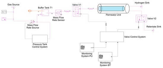
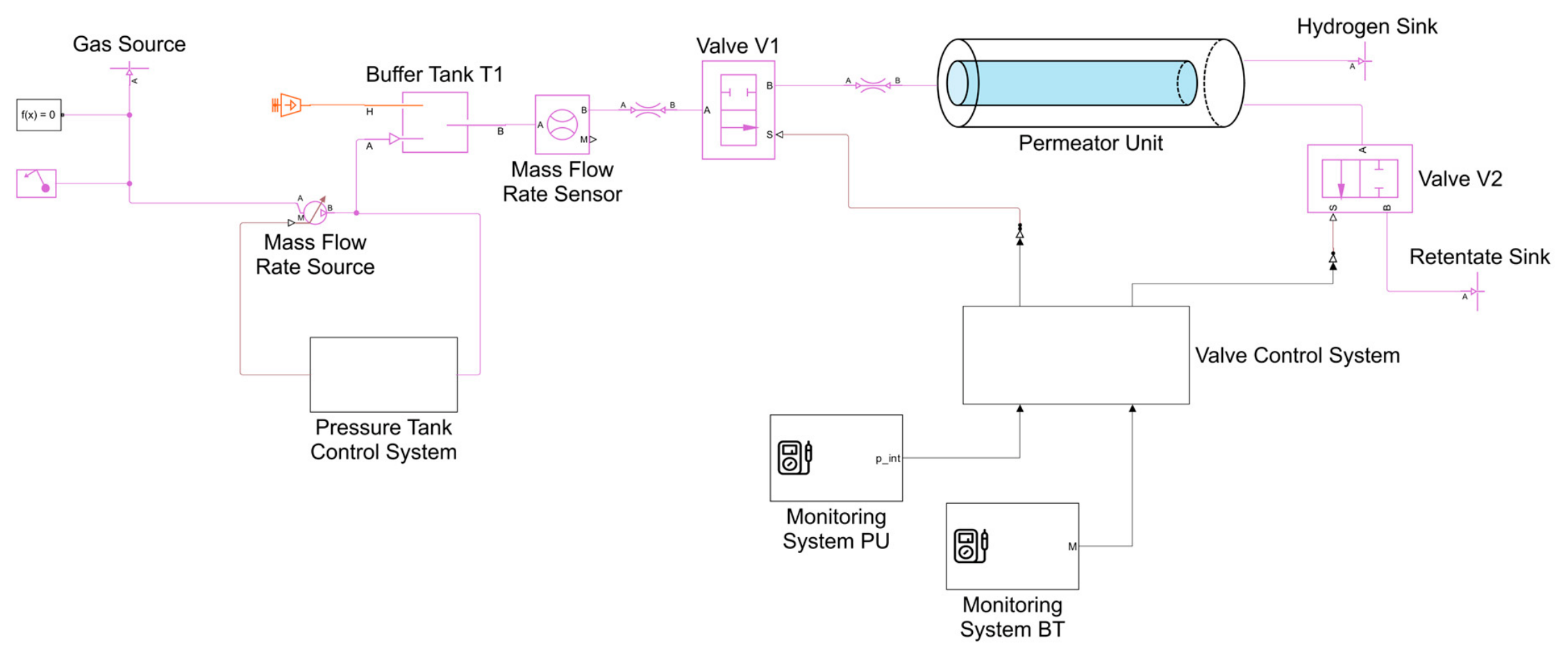
A preliminary scheme of the Pd-Ag Permeator System is shown in Figure 3: the Permeator Unit is connected to Buffer Tank T1 through Valve V1, to the Retentate Sink through Valve V2 and to the Hydrogen Sink. Buffer Tank T1 is a Constant-Volume Chamber block which is in turn connected to a Gas Source and is kept at constant pressure thanks to the Pressure Tank Control System, consisting of a PID controller. When pressure in T1 decreases, the PID controller sends a signal to a Mass Flow Rate Source, which restores the tank pressure. To reduce the complexity of the system without affecting the physics, the pressure of Buffer Tank T1 has been set to a different value with respect to the one reported in Table 1, which also avoids the need for a reducing valve. The list of parameters and operating conditions of the Simscape model is displayed in Table 3.
Figure 3.
Simscape model of the Pd-Ag Permeator System.
Table 3.
Simscape model parameters and operating conditions.
The Valve Control System includes a Stateflow block which acts as the logical controller of Valve V1 and Valve V2. The signals sent to the Valve Control System are read by the Monitoring System, consisting of a Probe block. The list of Simscape objects used in the model can be found in Supplementary Materials Table S1.
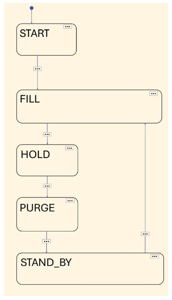
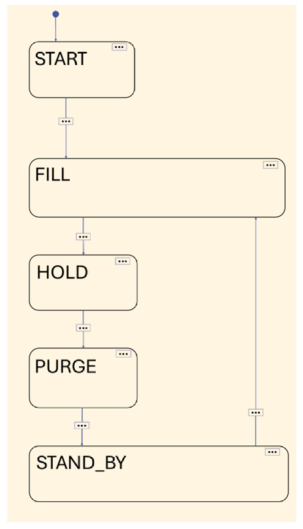
The purposes of the Stateflow block in the Valve Control System are reading Monitoring System signals and switching between different operational states depending on specific conditions and timers, which are described in Figure 4 and Table 4.
Figure 4.
Stateflow chart.
Table 4.
List of Stateflow operational states.
At the beginning, the pressure inside the permeator lumen is set to 10 Pa, and the Stateflow is in the “START” state, with Valve V1 and Valve V2 closed; during the “FILL” state, Valve V1 is opened, Valve V2 is closed, and the gas flow rate enters the permeator lumen; when a specified permeation flow rate is reached, the “HOLD” state starts with Valve V1 and Valve V2 both closed, waiting for the remaining hydrogen to end the permeation process; in the “PURGE” state, Valve V1 remains closed, and Valve V2 is opened, so the permeator is emptied until it reaches a specified value of internal pressure; in the “STAND_BY” state, Valve V2 is closed, and the system stays as it is for 10 s before returning to the “FILL” state.
4. Model Validation on HyPe Experimental Facility
An experimental campaign carried out at the Hydrogen Permeation (HyPe) facility [32] located at the ENEA Frascati Laboratories allowed us to collect useful data for the validation of the model.
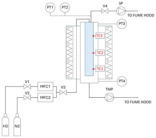
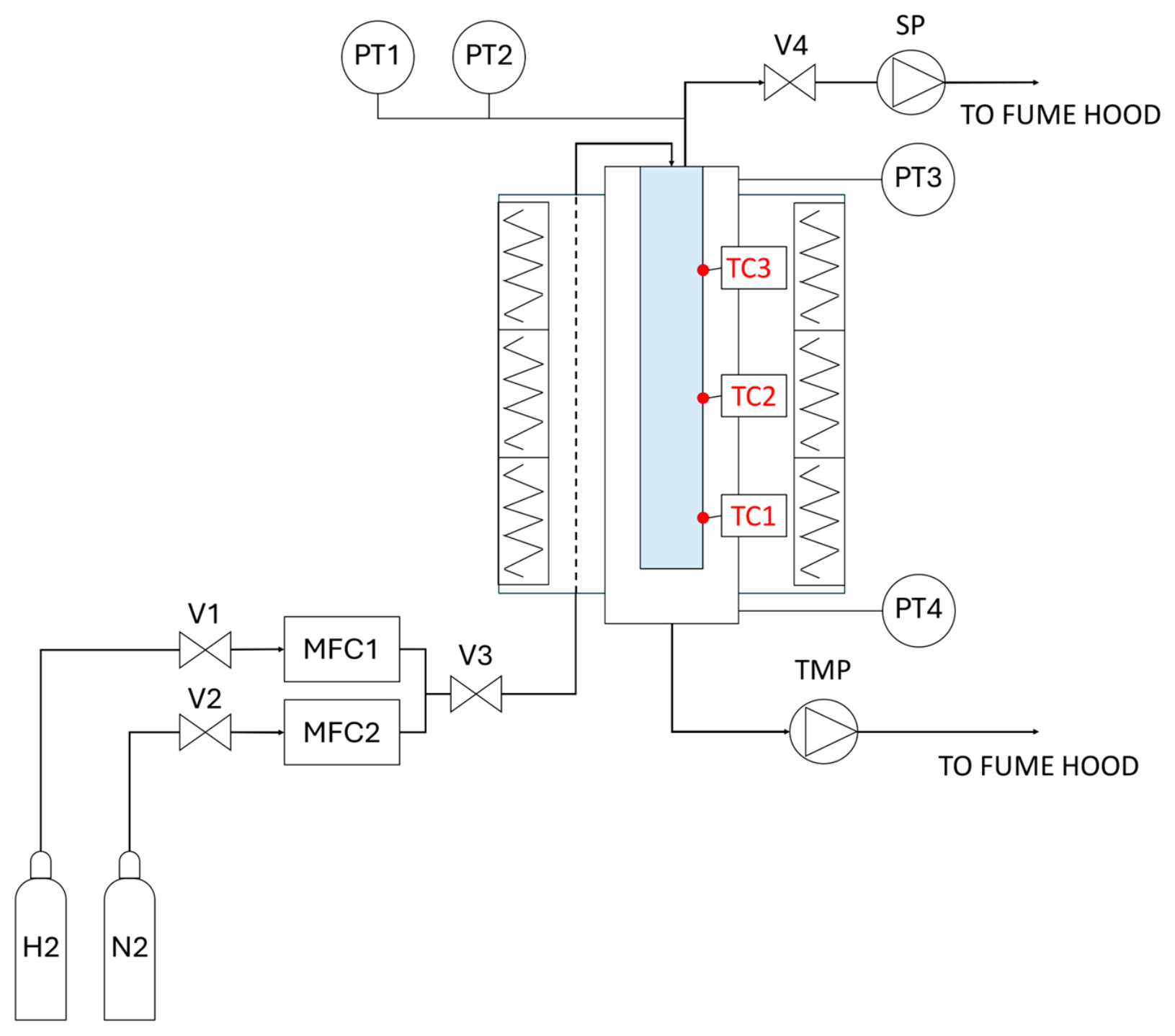
The main components of the Facility and the instrumentation are presented in Figure 5 and Table 5. The Pd-Ag membrane (coloured in light blue) has a length of 510 mm, an outer diameter of 9.93 mm and a thickness of 102 µm. The membrane is surrounded by an external tube connected to a turbopump (TMP), which features a hydrogen pumping speed of 900 L·s−1 and a base pressure of 10−10 mbar. The Permeator Unit is thus divided into lumen and shell sides by the Pd-Ag membrane. Pressure on the shell side is measured by Pressure Transducers PT3 and PT4. Lumen pressure is monitored through Pressure Transducers PT1 and PT2, while membrane temperature is read at three points, TC1, TC2 and TC3, highlighted in red in Figure 5. The lumen is also connected through Valve V4 to the scroll pump (SP; featuring a max pumping speed of 3.9 L·s−1 and a typical ultimate pressure of 3 Pa) and through Valve V3 to the feed line. The feed gas mixture is prepared using mass flow controllers MFC1 and MFC2, which are connected through Valves V1 and V2 to gas cylinders containing hydrogen and nitrogen.
Figure 5.
Scheme of the HyPe test facility.
Table 5.
HyPe instrumentation list.
The feed gas is pre-heated before entering the membrane lumen, passing through three radiative ceramic heaters, distributed along the permeator length and represented by electric resistances in Figure 5. Then the mixture enters the lumen, where hydrogen can permeate, while non-permeating species form the retentate gas, which can be vented through the SP.
The operating conditions of the HyPe facility are slightly different with respect to the one foreseen for the SRF Facility. In fact, before the Permeator Unit, there is not a buffer tank kept at constant pressure, and the feed flow rate is imposed by the two mass flow controllers.
Nevertheless, the tests performed at the HyPe facility consider a composition of the feed gas of the same order of magnitude of the one foreseen for the SORGENTINA project and the same closed configuration for the Permeator Unit. In fact, the scope is to verify if the filter-mode operation is feasible for the SRF project.
The experimental procedure is composed of four phases. After the operative temperature has been reached and the Unit has been properly evacuated, an initial flow rate containing only hydrogen is fed through MFC1, having Valve V4 closed. The H2 flows into the permeator lumen, and an equilibrium pressure is reached (hydrogen phase). After approximately 2 min, impurities are fed through MFC2. Non-permeating species start accumulating inside the lumen and the total pressure increases until the target value of 105 Pa is reached (impurity phase). At this point, the total flow rate is interrupted by closing Valve V3: the hydrogen remained in the lumen permeates through the membrane until equilibrium is reached (cleaning phase). In the end, Valve V4 is opened, and the lumen is emptied by turning on the scroll pump (SP; emptying phase).
The test matrix consists of ten experiments, divided into two groups and summarised in Table 6. Group 1 tests investigate the effect of increasing the feed flow rate while keeping the same composition, whereas Group 2 tests assess the impact of varying the impurity concentration at the feed while keeping the same throughput.
Table 6.
Experimental test matrix.
Model Comparison with Experimental Results
As far as Python and Simscape simulations are concerned, the input data used for the simulations are the geometrical characteristics of the membrane used in the HyPe facility and the measured quantities from the facility instrumentation (temperature, inlet flow rates and shell pressures), as shown in Table 7. As for temperature, an average value of TC1, TC2 and TC3 is used. The same is considered for shell pressure, taking the average value of PT3 and PT4.
Table 7.
Measured quantities used as input for the simulations.
Regarding hydrogen permeability, the value used for the models comes from experimental tests performed at the same facility that aimed at evaluating permeability at the operating temperature of 673 K. The values used as input for the simulations are listed in Table 8 [32], which shows permeability as a function of lumen and shell pressure.
Table 8.
Permeability values used as input for the simulations.
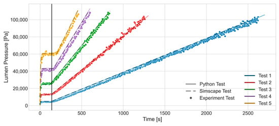
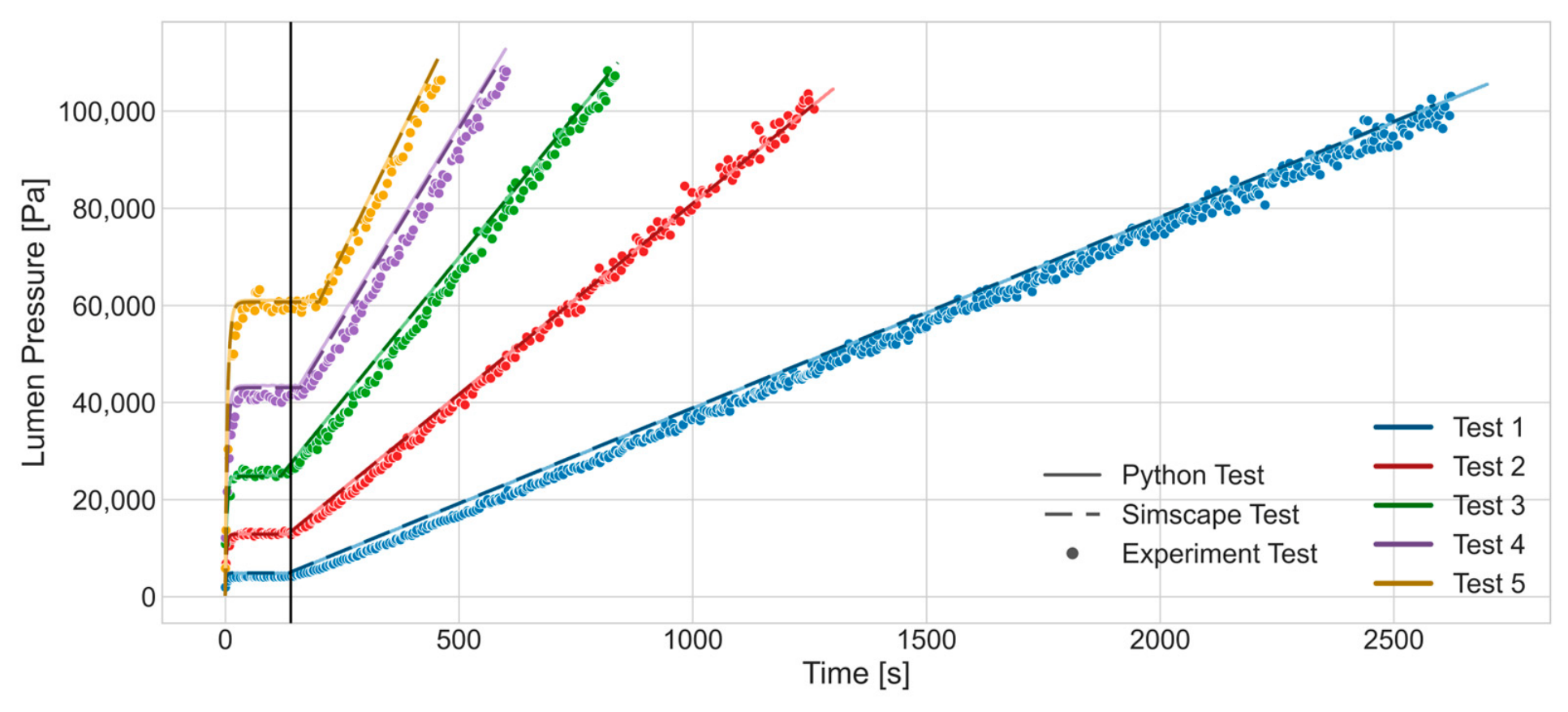
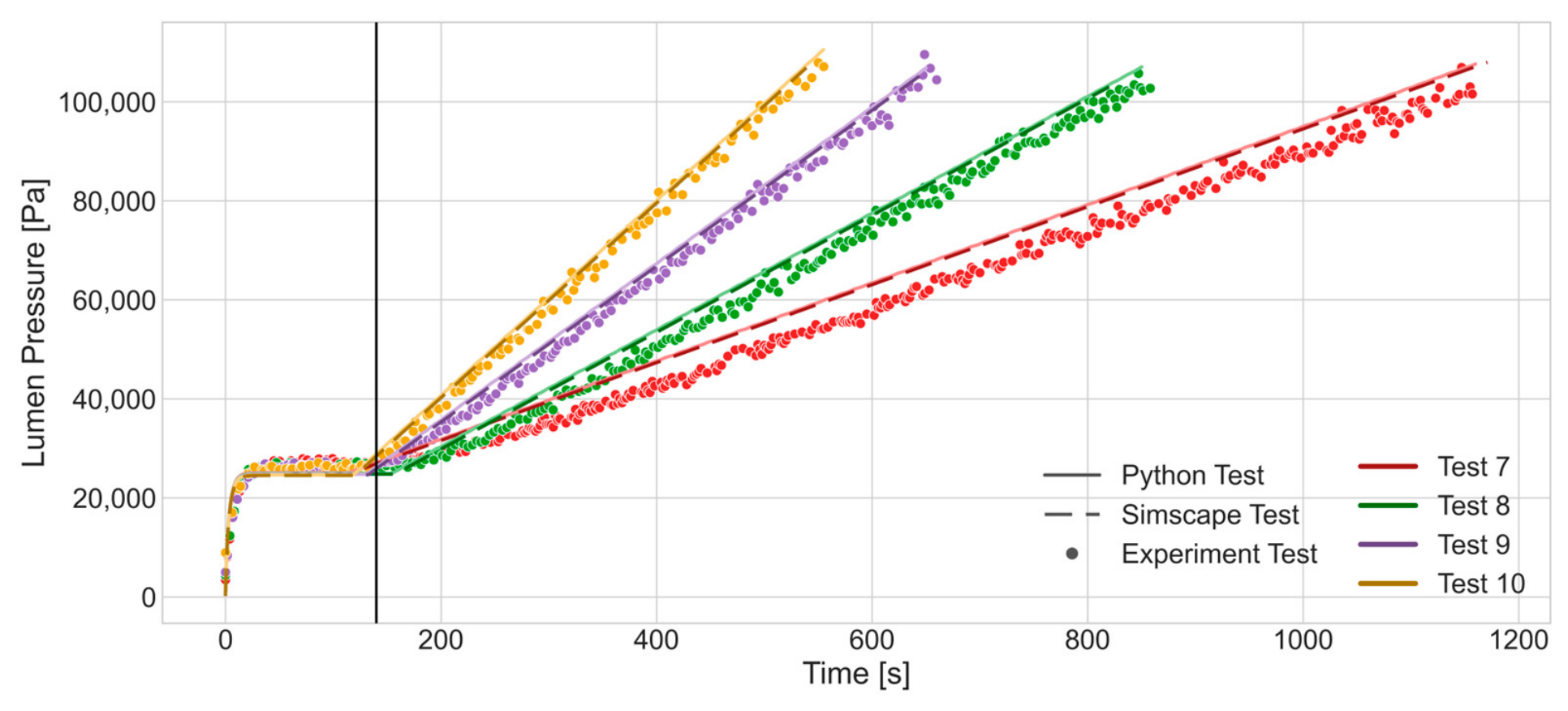
The outcomes of Group 1 and Group 2 tests are illustrated in Figure 6 and Figure 7 together with the Python and Simscape simulation results. The graphs show the trend of lumen pressure as a function of time. When only hydrogen is fed, the pressure in the lumen reaches the steady-state constant value. After approximately 2 min, impurities are added to the feed stream (indicated in the graph by a black vertical line) and pressure trend assumes a linear behaviour, whose slope depends on the value of the impurity flow rate.
Figure 6.
Group 1 tests with Python and Simscape simulation results.
Figure 7.
Group 2 tests with Python and Simscape simulation results.
The value of the pressure in the first part of the test (hydrogen phase) depends on temperature, on the inlet hydrogen flow rate and on the hydrogen pressure on the shell side. More specifically, pressure in the lumen reaches a higher equilibrium value for higher inlet flow rates and this can be verified by comparing Group 1 tests, in which the flow rate varies approximately from 100 to 500 mL·min−1, with respect to Group 2 tests, in which the flow rate remains almost constant.
The observed increase in the lumen pressure is primarily driven by the accumulation of impurities, which remain confined inside the membrane. Since real-time measurement of the internal gas composition is not possible, the contribution of the individual species can be estimated only from the model’s prediction. The hydrogen partial pressure maintains a constant value during the test, as the continuous feed compensates for permeation. The linear increase in pressure is therefore attributable to the accumulation of impurities.
During the experimental campaign, the pressure evolution of Test 6 deviated significantly from the trend of all other tests, showing a delayed pressure increase in the initial phase most likely attributable to some instabilities in the experimental conditions. Unfortunately, no real-time information on the composition of the gas species inside the lumen is available, so it is not possible to understand the cause of this behaviour. For this reason, the experimental result of Test 6 has not been included in the validation process. Nevertheless, this exclusion does not undermine the overall validity of the modelling approach within the range of operating conditions investigated, since the remaining tests showed good agreement between the experimental data and model predictions, as can be seen in Table 9, which reports the relative errors of both the Python and Simscape models with respect to the experimental measurements. For each model, the relative error () at the experimental time instant i was computed as follows:
where is the experimental value measured at time i, while is the corresponding value predicted by model m at the same time instant. The average relative error was then calculated over all N time points at which experimental measurements were available:
Table 9.
Relative errors of simulated model with respect to experimental tests.
For all tests, the relative error remains within an acceptable range (below 9%), indicating good agreement between the numerical models and the experimental results.
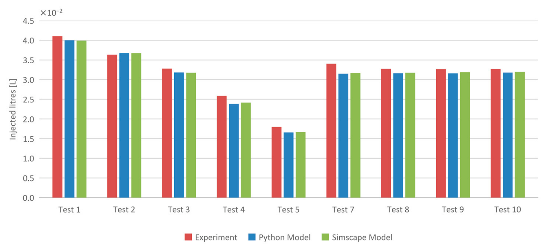
A further analysis can be done considering the filling times of the membrane, which are listed in Table 10. What can be noticed is that filling times for tests of Group 1 are not linear with the impurity flow rate, and this is because of the starting hydrogen pressure: in fact, pressure on the shell side is not constant, and this leads to increasing stationary hydrogen pressure on the lumen side, as the inlet flow rate increases. So, at higher flow rates, there is less available pressure before reaching the threshold of 105 Pa, meaning a lower quantity of impurities inserted in the lumen, as detailed in Figure 8. The bar chart shows the comparison of the quantity of impurities injected for each test between the experiment and the models. It is possible to notice that for Group 1, the litres of impurities decrease from Test 1 to Test 5, while for Group 2, the quantity injected is almost the same for each test, having the same stationary hydrogen pressure at the beginning.
Table 10.
Membrane filling times for experimental tests.
Figure 8.
Quantity of impurities injected for each test.
5. Model Application to the SORGENTINA Tritium Facility
The models, validated against the available dataset, were applied to simulate the hydrogen permeation process under the operating conditions of the SORGENTINA project. The Pd-Ag Permeator System of SORGENTINA foresees constant-pressure buffer tank instead of mass flow controllers on the feed line of the system. In this configuration, the mass flow rate is subject only to the difference in pressure between the membrane and the buffer tank. As introduced in Section 3.2, the total inlet flow rate decreases with time, and this affects the behaviour of the partial pressure of the species inside the membrane.
As the good agreement between the Python and Simscape models has been demonstrated in the Section Model Comparison with Experimental Results, the application in this section focuses exclusively on the Simscape implementation. Two configurations were investigated: a single-membrane configuration, aimed at verifying the correct implementation of the control logic, and a multi-membrane configuration designed to achieve continuous operation at the system level.
The input data for the simulations include the geometrical characteristics of the membrane and the operating conditions foreseen for the SRF project, as introduced in Section 3.1. Regarding hydrogen permeability, the value adopted was selected from Table 8 [32] as the one corresponding to the conditions closest to those expected for the SRF Tritium Facility (7.394 × 10⁻⁹ mol·m−1·s−1·Pa−0.5). Given the isotopic dependence of permeability discussed in Section 3.2, this value should be considered an approximation. To assess the sensitivity of the results to this uncertainty, a variation of ±50% with respect to the reference value was considered, consistent with the estimated difference in effective permeability between hydrogen and an equimolar D/T mixture. The results of this analysis are discussed in Section 5.2.
5.1. Simscape Single-Membrane Configuration
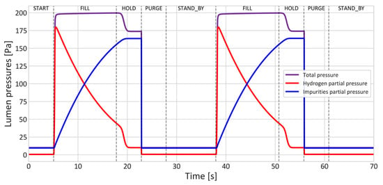
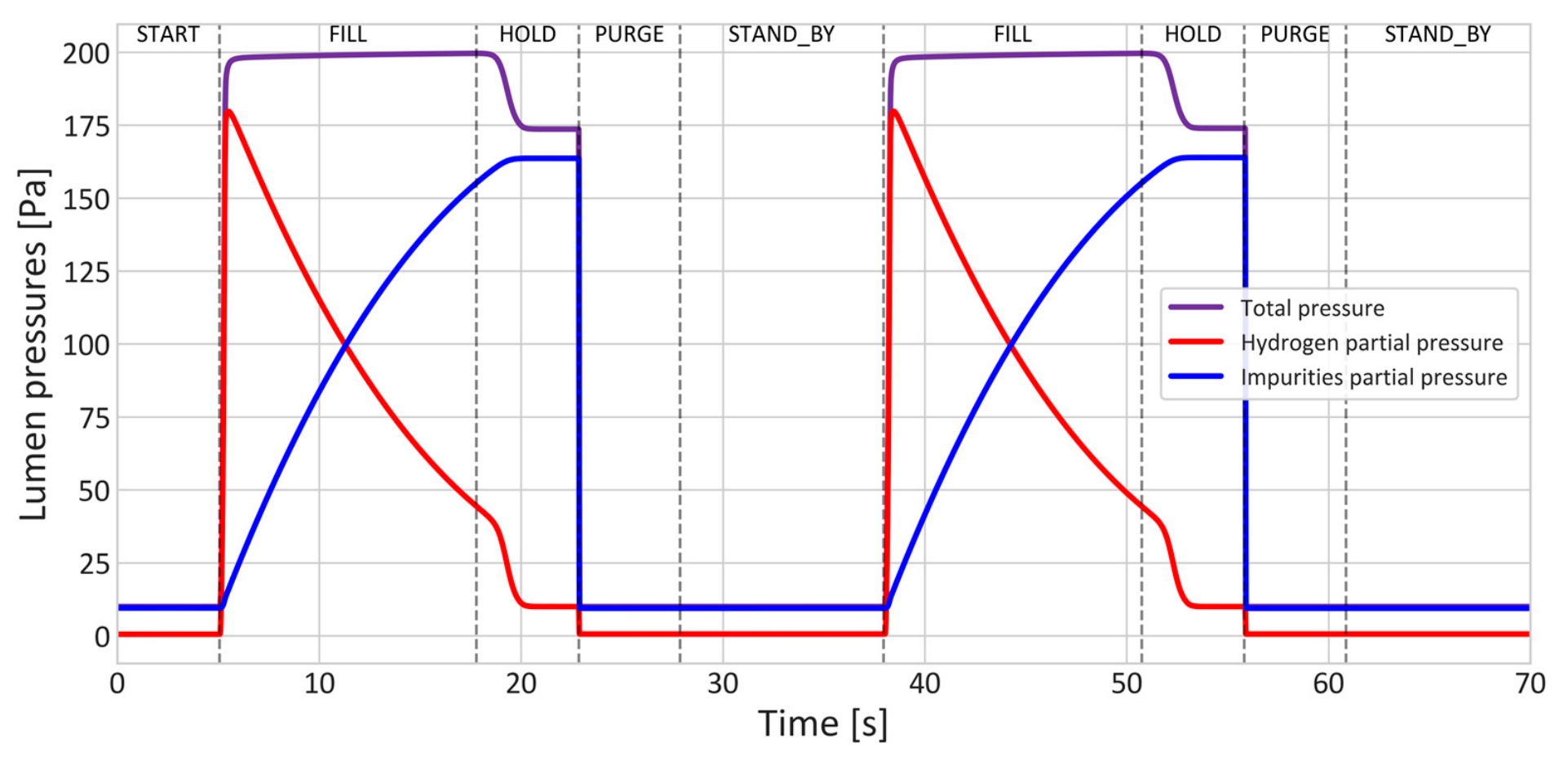
The results of the simulation with the Simscape model in the single-membrane configuration are shown in Figure 9 and Figure 10, which show the profile of lumen pressure and permeation flow rate, respectively. The simulation time covers two cycles of the process, and the states described in Figure 4 and Table 4 can be recognised in Figure 9. During the FILL state, the inlet valve is open, with the retentate valve closed, and the total pressure remains at a value of approximately 200 Pa, given by the gradual increase in the partial pressure of the impurities (blue line in Figure 9) and the contemporary decrease in hydrogen partial pressure (red line in Figure 9); in the HOLD state, all valves are closed, and the hydrogen partial pressure reaches the value of the pressure on the shell side; in the PURGE state, the retentate valve is opened, and the membrane is emptied; in the STAND_BY state all valves are closed, and the system stays as it is until the next FILL state.
Figure 9.
Simscape time evolution of lumen pressure (2 cycles).
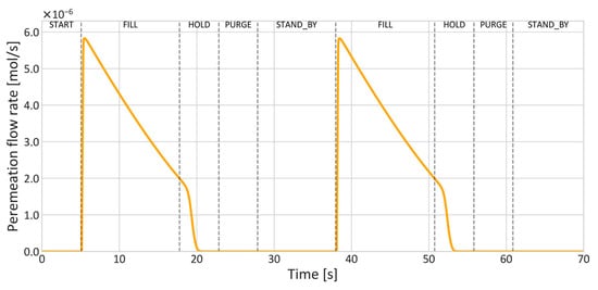
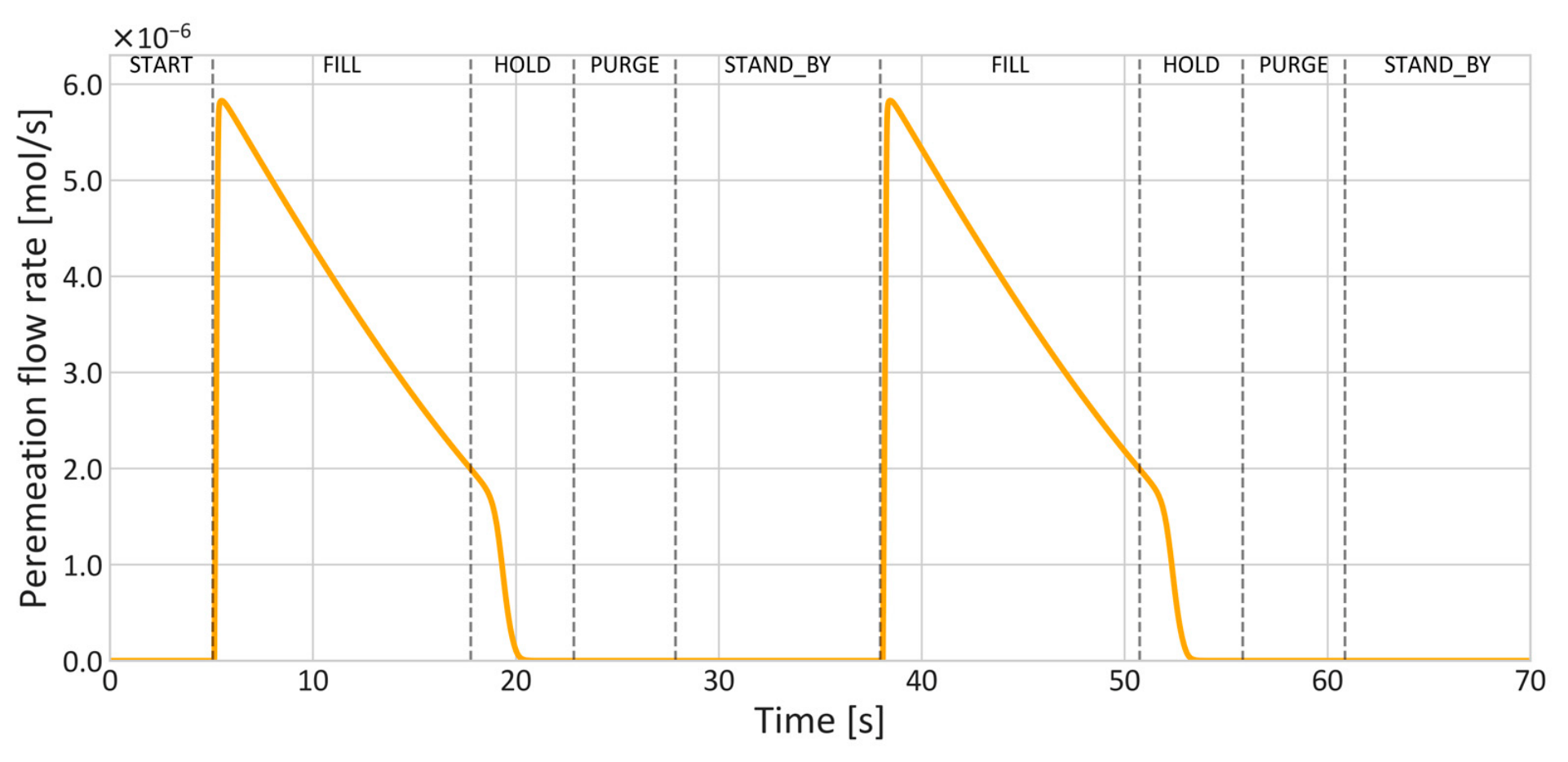
Figure 10.
Simscape time evolution of permeation flow rate (2 cycles).
Concerning the graph shown in Figure 10, the permeation flow rate at the beginning of the FILL state shows a peak of approximately 5.8 × 10⁻⁶ mol·s−1, and then it decreases as the hydrogen partial pressure inside the lumen decreases. The transition to the HOLD state occurs when the permeation flow rate drops to 2 × 10⁻⁶ mol·s−1, which subsequently approaches zero. During the PURGE state, the total pressure in the lumen is reduced to a value equal to the Retentate Sink pressure (see operating conditions in Table 3), so the hydrogen partial pressure falls below the value of the Hydrogen Sink pressure (10 Pa) which can be also seen in Figure 9. Since the hydrogen partial pressure in the shell is forced to remain constant, the resulting pressure gradient would cause permeation from the shell side towards the lumen. This condition should be reflected by a negative permeation flow rate in Figure 10. However, this behaviour is not reproduced by the model. From an operational point of view, the pressure on the shell side should not remain constant but should decrease as the permeation flow rate decreases, depending on the characteristics of the pumping system. Considering the pump characteristics of TMP and SP described in Section 4, the shell-side pressure is expected to remain well below the lumen-side hydrogen partial pressure throughout the PURGE state, confirming that the conditions for back-flow permeation are not met under the foreseen operating conditions. In line with this, the custom Simscape component representing the permeator (Permeator Unit) is configured to prevent back-flow permeation under all operating conditions, including cases where shell-side pressure exceeds lumen-side pressure, in order to ensure computational robustness and avoid unexpected numerical errors. It should be noted that if back-flow permeation were to occur, hydrogen from the shell side would re-enter the lumen during the PURGE state, potentially increasing the total amount to be discharged. The current model does not account for this contribution, so the predicted residual tritium release is conditional on the assumption that reverse permeation does not occur and may underestimate the actual release if tritium permeates back into the lumen during the PURGE state. A more realistic representation of the shell-side pumping system, identified as a direction for future work, would allow this effect to be properly addressed, replacing the current assumption of constant shell-side pressure with a dynamic description of the pumping behaviour.
The results of the single-membrane configuration confirm the correct implementation of the control logic: the Permeator Unit follows the expected sequence of operational states in the correct order, with the transitions occurring at the predefined conditions. The lumen pressure and permeation flow rate profiles are consistent with the physical behaviour described in Section 3.2.
Concerning the residual quantity of hydrogen in the lumen volume before the PURGE state, it is, in principle, related to the shell side pressure of the Permeator Unit. During the HOLD state, when the inlet flow rate is stopped, the hydrogen partial pressure in the lumen rapidly reaches the value of the shell pressure, and permeation terminates. The residual hydrogen therefore represents the quantity that cannot be recovered by permeation and must be discharged. For the single-membrane configuration, this amount is approximately of 3.37 × 10⁻⁸ mol per cycle.
5.2. Simscape Multi-Membrane Configuration
The single-membrane Simscape model described in Section 3.2 was extended to a multi-membrane configuration in which the Permeator Units operate in parallel. The extended configuration of the Simscape model is illustrated in Supplementary Materials Figure S1. The Units operate in sequence with a partial overlap between successive activations to ensure continuous flow at the Buffer Tank T1 outlet. The number of Units and membrane length were selected based on three criteria: the mean outlet flow rate from Buffer Tank T1 must meet the requirements of the SRF project, the flow rate oscillations must be minimised, and the activation sequence must be consistent, meaning that each Unit needs to complete its full cycle before being re-activated. This last condition represents a constraint on the minimum number of Units: with six Units, for instance, the first Unit had not yet completed its cycle by the time the sixth was activated, making continuous operation not feasible. The resulting configuration foresees seven Permeator Units, each with a membrane length of 0.12 m.
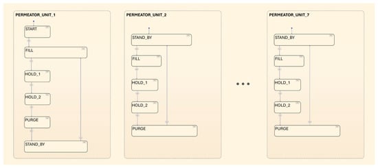
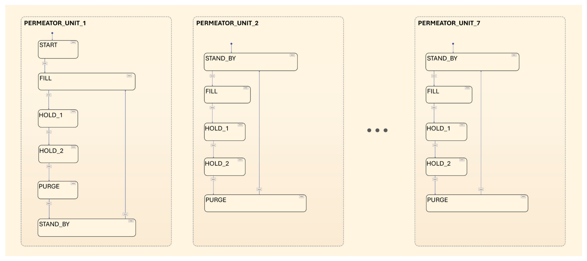
The physical components were replicated for each of the seven Permeator Units, while the Stateflow block used as control logic was revised to manage the membrane sequence. The modified Stateflow chart is shown in Figure 11.
Figure 11.
Stateflow chart in the multi-membrane configuration.
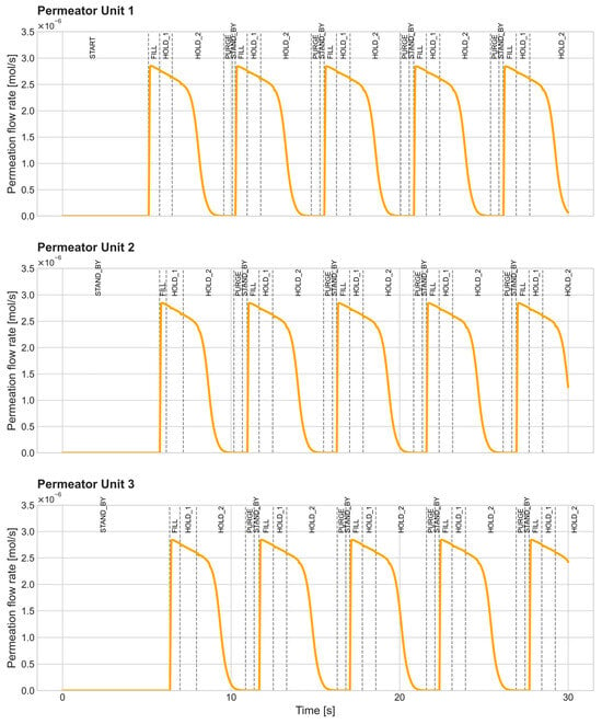
Each Permeator Unit is governed by an independent state sequence: PERMEATOR_UNIT_1 begins the cycle from the START state, progressing through FILL, HOLD_1, HOLD_2, PURGE and STAND_BY states, while the following Units begin their cycle from the STAND_BY state. The change of Unit occurs during the FILL state when the flow rate entering the membrane drops to 9 × 10⁻⁶ mol·s−1 and a command is sent to the following Unit.
With respect to the single-membrane configuration, an intermediate state (HOLD_1) has been introduced to handle the overlap between successive activations, preventing the flow rate coming from Buffer Tank T1 from dropping to zero. The HOLD_2 state has the role originally assigned to the HOLD state in the single-membrane configuration.
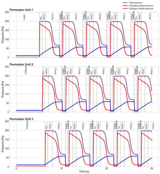
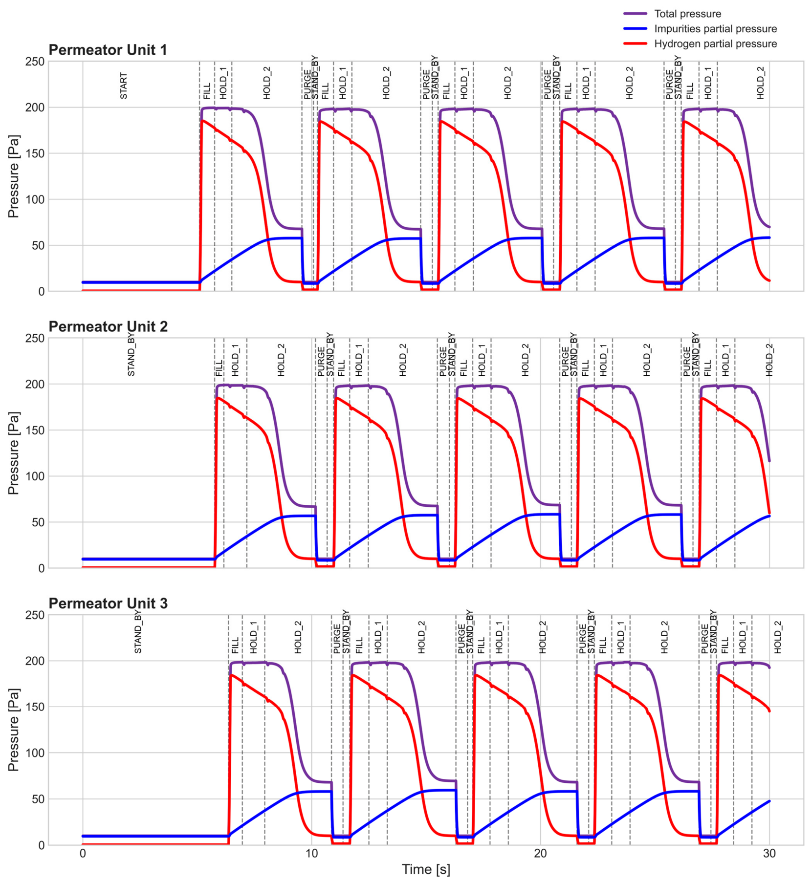
The results of a simulation of 30 s in the multi-membrane configuration are illustrated in Figure 12 and Figure 13, showing the lumen pressure and the permeation flow rate for each Permeator Unit, respectively. For simplicity, only the cycles of the first three Units are illustrated, as the remaining Units exhibit identical behaviour with a time shift corresponding to their activation sequence. Each Unit undergoes the same sequence of operational states which are shifted in time, completing a cycle in about 5 s. The lumen pressures and flow rate profiles are similar in shape to those described for the single-membrane configuration, except for the fact that each Permeator Unit remains active for less time. In fact, the partial pressure of impurities reaches approximately the value of 60 Pa before the PURGE state, instead of filling the membrane with more impurities. Concerning the permeation flow rate, it reaches a peak value of about 2.8 × 10⁻⁶ mol·s−1 consistently across Permeator Units and across cycles.
Figure 12.
Simscape time evolution of lumen pressure in multi-membrane configuration.
Figure 13.
Simscape time evolution of permeation flow rate in multi-membrane configuration.
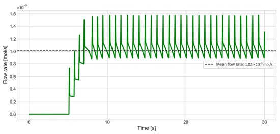
As can be seen in Figure 14, which shows the flow rate exiting Buffer Tank T1, there is an initial transient stage until the fourth Permeator Unit is activated. After that point, the flow rate oscillates between the values of 1.13 × 10⁻⁵ mol·s−1 and 9 × 10⁻⁶ mol·s−1 (peaks excluded), having a mean flow rate handled by the system of about 1.02 × 10⁻⁵ mol·s−1.
Figure 14.
Buffer Tank T1 outlet flow rate.
The multi-membrane configuration demonstrates that continuous operation at the system level can be achieved through the sequential activation of the Permeator Units. Once steady-state operation is reached, the system can handle a mean flow rate of 1.02 × 10⁻⁵ mol·s−1, without excessive oscillation in inlet flow due to membrane switch (about 20%), meeting the requirements of the SRF Tritium Facility. What can be also noticed in Figure 14 is the presence of periodic peaks, due to the activation of each Permeator Unit, i.e., to inlet-valve opening. These peaks can be attributed to the simplified representation of the system, which does not account for pipe volumes and component inertia. It would be expected that these aspects dampen the peaks, resulting in a smoother flow rate profile. Moreover, the initial transient stage observed in Figure 14 is an expected behaviour related to the sequential activation of the Permeator Units. In fact, each Unit remains temporarily active until the inlet valve is closed during the HOLD_2 state: this leads to a condition in which four membranes are active at the same time, which allows the required flow rate to be managed.
Concerning the dimension of the membranes, the length adopted in this configuration (0.12 m) is shorter than the one foreseen for the SRF project (0.25 m). In fact, maintaining a dimension of 0.25 m would result in a slightly higher mean flow rate (1.13 × 10⁻⁵ mol·s−1) and larger oscillations of approximately 35%. These considerations are also relevant considering a variation in the permeability value, as discussed in Section 3.2. In the case of higher permeability (+50%), the system achieves a mean managed flow rate of 1.1 × 10⁻⁵ mol·s−1 with oscillations of approximately 25%, while the overall behaviour remains consistent with the reference case. In the case of lower permeability (−50%), representative of D/T operation, a membrane length of 0.22 m would be required to achieve the same performance as the reference H2 configuration with seven Permeator Units.
Regarding the residual hydrogen in the lumen volume for the multi-membrane configuration, each Permeator Unit contains approximately 1.62 × 10⁻⁸ mol that must be discharged in the PURGE state. For the actual D/T application, the residual inventory would consist of a D/T mixture rather than pure hydrogen; assuming an equimolar composition, the tritium content would amount to approximately half of this value, that is, 8.09 × 10⁻⁹ mol per Unit. Considering the activation sequence of the Permeator Units, a discharge occurs on average every 0.75 s. Over a continuous operation of 24 h, this results in a total tritium release of approximately 5.60 × 10⁻³ g·day−1. In the case of lower permeability, the residual quantity per Unit increases due to the larger lumen volume, while the discharge frequency remains approximately unchanged. This results in a higher release of approximately 1.06 × 10⁻² g·day−1.
6. Conclusions and Future Perspectives
This paper presented a transient model for the analysis of the Pd-Ag Permeator System of the Tritium Facility of SORGENTINA-RF operating in a closed configuration (filter mode). The fundamental mechanisms of the permeation process were addressed with a Python-based model, which provided the mathematical basis for the subsequent Simscape implementation incorporating the control logic required for system-level operation in single-membrane and multi-membrane configurations.
The models were validated against experimental data collected at the HyPe facility of the ENEA Frascati Laboratories, showing good agreement, with average relative errors below 9%.
The models were then applied to the SRF Tritium Facility to assess system behaviour under the operating conditions foreseen for the project. The single-membrane configuration confirmed the correct implementation of the control logic, with the Permeator Unit following the expected sequence of operational states. The multi-membrane configuration, consisting of seven Permeator Units of 0.12 m in length activated in sequence, demonstrated that continuous operation at the system level can be achieved, with a mean managed flow rate of approximately 1.02 × 10⁻⁵ mol·s−1, once steady-state operation is reached. This result establishes a minimum design criterion for filter-mode continuous operation. Concerning the residual tritium release, the sequential activation scheme results in an average discharge of approximately 5.60 × 10⁻³ g·day−1 over 24 h of continuous operation. This estimate may serve as input to future assessments of tritium inventories and safety analyses for the SRF Tritium Facility.
A sensitivity analysis on the adopted permeability value was carried out by varying it by ±50% with respect to the reference value. In the case of higher permeability (+50%), the system achieves a mean managed flow rate of 1.09 × 10⁻⁵ mol·s−1 with oscillations of approximately 25%, while the overall behaviour remains consistent with the reference case. In the case of lower permeability (−50%), representative of D/T operation, a membrane length of approximately 0.22 m is required to meet the flow rate requirements with seven Permeator Units. Under this condition, the larger lumen volume results in a higher total tritium discharge of approximately 1.06 × 10⁻² g·day−1, which should be taken into account when considering D/T operation.
This work provides a preliminary analysis and a useful tool to support the design of the Pd-Ag Permeator System for the SORGENTINA-RF Tritium Facility. To consolidate the facility design, additional work is required, including the optimisation of interface parameters, the assessment of membrane characteristics, and extensive sensitivity analyses of the key model inputs. Furthermore, the Simscape model could be extended to incorporate a more realistic representation of the auxiliary components—in particular the shell-side pumping system—which would allow for a more accurate prediction of system behaviour. These activities will contribute to the development of detailed guidelines for the SRF project.
Supplementary Materials
The following supporting information can be downloaded at: https://www.mdpi.com/article/10.3390/membranes16110374/s1, Table S1: List of Simscape Objects; Figure S1: Simscape model of the Pd-Ag Permeator System in the multi-membrane configuration.
Author Contributions
Conceptualisation, S.C., R.T., V.N. and A.S.; Methodology, S.C., R.T., V.N. and A.S.; Software, S.C.; Validation, S.C.; Resources, V.N. and A.S.; Data Curation, S.C.; Writing—original draft preparation, S.C., R.T., V.N. and A.S.; Writing—review and editing, S.C., R.T., V.N. and A.S.; Supervision, R.T., V.N. and A.S. All authors have read and agreed to the published version of the manuscript.
Funding
This work is part of the project PNRR-NGEU, which has received funding from MUR—DM 118/2023.
Data Availability Statement
The data presented in this study are available upon request from the corresponding author. The data are not publicly available due to restrictions from the project institution.
Acknowledgments
The authors acknowledge the Regione Emilia Romagna–ENEA agreement for the project “SORGENTINA RF–Thermomechanical Demonstration”. The SRF Collaboration: Antonino Pietropaolo 2, Nicola Fonnesu 2, Ranieri Marinari 2, Fabio Moro 2, Antonietta Rizzo 2, Nicholas Terranova 2, Konstantina Voukelatou 2, Danilo Dongiovanni 2, Davide Flammini 2, Andrea Mancini 2, Alexander Rydzy 2, Demis Santoli 2, Camillo Sartorio 2, Valerio Sermenghi 2, Ivan Panov Spassovsky 2, Silvano Tosti 2, Alberto Ubaldini 2, Pietro Zito 2, Agostina Orefice 2, Gian Marco Contessa 3, Marco Lamberti 4, David Guidoni 4, Bruno Mastroianni 4, and Paolo Ferrari 5. 2 ENEA Nuclear Department, Italy; 3 Istituto Superiore di Sanità, Italy; 4 ENEA Management of Infrastructures and Services, Italy; 5 ENEA Institute of Radiation Protection.
Conflicts of Interest
The authors declare no conflicts of interest.
References
- Agostini, P.; Angiolini, M.; Alberghi, C.; Candido, L.; Capogni, M.; Capone, M.; Cataldo, S.; D’Annibale, F.; D’Arienzo, M.; Diamanti, D.; et al. SORGENTINA-RF project: Fusion neutrons for 99Mo medical radioisotope. Eur. Phys. J. Plus 2021, 136, 1140, Correction in Eur. Phys. J. Plus 2022, 137, 425. https://doi.org/10.1140/epjp/s13360-022-02485-1. [Google Scholar] [CrossRef] [Scilit]
- Fonnesu, N.; Scaglione, S.; Spassovsky, I.P.; Pietropaolo, A.; Zito, P.; The SRF Collaboration. On the Definition of the Deuterium-Tritium Ion Beam Parameters for the SORGENTINA-RF Fusion Neutron Source. Eur. Phys. J. Plus 2022, 137, 1150, Correction in Eur. Phys. J. Plus 2022, 137, 1313. https://doi.org/10.1140/epjp/s13360-022-03475-z. [Google Scholar] [CrossRef] [Scilit]
- Fonnesu, N.; Scaglione, S.; Spassovsky, I.P.; Zito, P.; Pietropaolo, A.; The SRF Collaboration. On the Expected Performance of the SORGENTINA-RF Fusion Neutron Source. Eur. Phys. J. Plus 2022, 137, 1240. [Google Scholar] [CrossRef] [Scilit]
- Kovari, M.; Coleman, M.; Cristescu, I.; Smith, R. Tritium Resources Available for Fusion Reactors. Nucl. Fusion 2018, 58, 026010. [Google Scholar] [CrossRef] [Scilit]
- Paglieri, S.N.; Way, J.D. Innovations in Palladium Membrane Research. Sep. Purif. Methods 2002, 31, 1–169. [Google Scholar] [CrossRef] [Scilit]
- Hatlevik, Ø.; Gade, S.K.; Keeling, M.K.; Thoen, P.M.; Davidson, A.P.; Way, J.D. Palladium and Palladium Alloy Membranes for Hydrogen Separation and Production: History, Fabrication Strategies, and Current Performance. Sep. Purif. Technol. 2010, 73, 59–64. [Google Scholar] [CrossRef] [Scilit]
- Arratibel Plazaola, A.; Pacheco Tanaka, D.A.; Van Sint Annaland, M.; Gallucci, F. Recent Advances in Pd-Based Membranes for Membrane Reactors. Molecules 2017, 22, 51. [Google Scholar] [CrossRef] [Scilit] [PubMed]
- Bernardo, G.; Araújo, T.; da Silva Lopes, T.; Sousa, J.; Mendes, A. Recent advances in membrane technologies for hydrogen purification. Int. J. Hydrogen Energy 2020, 45, 7313–7338. [Google Scholar] [CrossRef] [Scilit]
- Konishi, S.; Yoshida, H.; Naruse, Y. A Design Study of a Palladium Diffuser for a D-T Fusion Reactor Fuel Clean-up System. J. Less-Common Met. 1983, 89, 457–464. [Google Scholar] [CrossRef] [Scilit]
- Bornschein, B.; Glugla, M.; Günther, K.; Lässer, R.; Le, T.L.; Simon, K.H.; Welte, S. Tritium tests with a technical PERMCAT for final clean-up of ITER exhaust gases. Fusion Eng. Des. 2003, 69, 51–56. [Google Scholar] [CrossRef] [Scilit]
- Glugla, M.; Antipenkov, A.; Beloglazov, S.; Caldwell-Nichols, C.; Cristescu, I.R.; Cristescu, I.; Day, C.; Doerr, L.; Girard, J.P.; Tada, E. The ITER tritium systems. Fusion Eng. Des. 2007, 82, 472–487. [Google Scholar] [CrossRef] [Scilit]
- Welte, S.; Ana, G.; Cristescu, I.; Dörr, L.; Kuntz, B.; Konrad, J.; Michling, R. Construction and Commissioning of an ITER Sized Pd/Ag Permeator for a Water Detritiation Experiment. Fusion Eng. Des. 2009, 84, 1969–1972. [Google Scholar] [CrossRef] [Scilit]
- Wilson, J.; Becnel, J.; Demange, D.; Rogers, B. The ITER Tokamak Exhaust Processing System Design and Substantiation. Fusion Sci. Technol. 2019, 75, 794–801. [Google Scholar] [CrossRef] [Scilit]
- Han, Y.; Ren, X.; Li, J.; Chen, C.; Zhen, S. Overview of the application of Pd-based membrane technology in fusion fuel cycles. Int. J. Hydrogen Energy 2026, 204, 153296. [Google Scholar] [CrossRef] [Scilit]
- Al-Mufachi, N.A.; Rees, N.V.; Steinberger-Wilkens, R. Hydrogen selective membranes: A review of palladium-based dense metal membranes. Renew. Sustain. Energy Rev. 2015, 47, 540–551. [Google Scholar] [CrossRef] [Scilit]
- Tosti, S. Supported and laminated Pd-based metallic membranes. Int. J. Hydrogen Energy 2003, 28, 1445–1454. [Google Scholar] [CrossRef] [Scilit]
- Tosti, S.; Bettinali, L.; Violante, V. Rolled thin Pd and Pd–Ag membranes for hydrogen separation and production. Int. J. Hydrogen Energy 2000, 25, 319–325. [Google Scholar] [CrossRef] [Scilit]
- Huang, Y.; Lu, G.; Zeng, Y.; Qian, N.; Chu, X.; Wang, G.; Wu, S.; Liu, W. Experimental and Simulation Analysis of Hydrogen Permeation Performance of Pd/Ag Permeator Used for Tritium Processing. Nucl. Technol. 2020, 206, 458–466. [Google Scholar] [CrossRef] [Scilit]
- Narcisi, V.; Tamborrini, L.; Farina, L.; Cortese, G.; Romanelli, F.; Santucci, A. Experimental and Numerical Analysis of a Pd–Ag Membrane Unit for Hydrogen Isotope Recovery in a Solid Blanket. Membranes 2023, 13, 578. [Google Scholar] [CrossRef] [Scilit] [PubMed]
- Fuerst, T.F.; Taylor, C.N.; Shimada, M. Deuterium Permeation Through a Self-Supported Palladium-Silver Membrane in Helium Gas Mixtures. IEEE Trans. Plasma Sci. 2024, 52, 3925–3929. [Google Scholar] [CrossRef] [Scilit]
- Abdou, M.; Riva, M.; Ying, A.; Day, C.; Loarte, A.; Baylor, L.R.; Humrickhouse, P.; Fuerst, T.F.; Cho, S. Physics and Technology Considerations for the Deuterium–Tritium Fuel Cycle and Conditions for Tritium Fuel Self Sufficiency. Nucl. Fusion 2021, 61, 013001. [Google Scholar] [CrossRef] [Scilit]
- Glugla, M.; Cristescu, I.R.; Cristescu, I.; Demange, D. Hydrogen isotope separation by permeation through palladium membranes. J. Nucl. Mater. 2006, 355, 47–53. [Google Scholar] [CrossRef] [Scilit]
- Fernández, A.; Casado, C.; Alique, D.; Calles, J.A.; Marugán, J. Modeling of H2 Permeation through Electroless Pore-Plated Composite Pd Membranes Using Computational Fluid Dynamics. Membranes 2021, 11, 123. [Google Scholar] [CrossRef] [Scilit] [PubMed]
- Albano, M.; Madeira, L.M.; Miguel, C.V. Use of Pd-Ag Membrane Reactors for Low-Temperature Dry Reforming of Biogas—A Simulation Study. Membranes 2023, 13, 630. [Google Scholar] [CrossRef] [Scilit] [PubMed]
- Hypes-Mayfield, V.; Troy, L.; Dogruel, D.; Kubic, W.; Dumont, J.H. Separation of Hydrogen Using Pd/Ag Membranes: Experimental and Modeling Results with Potential Application to Direct Internal Recycle. Fusion Sci. Technol. 2026, 82, 420–430. [Google Scholar] [CrossRef] [Scilit]
- Serra, E. Hydrogen and Tritium Kinetics in Fusion Reactor Materials. Ph.D. Thesis, Department of Physics, University of Salford, Salford, UK, 1996. [Google Scholar]
- The MathWorks, Inc. SimscapeTM, Version 24.2 (R2024b); The MathWorks, Inc.: Natick, MA, USA, 2024.
- Fujita, H.; Okada, S.; Fujita, K.; Sakamoto, H.; Higashi, K.; Hyodo, T. Ratio of Permeabilities of Tritium to Protium through Palladium-Alloy Membrane. J. Nucl. Sci. Technol. 1980, 17, 436–442. [Google Scholar] [CrossRef]
- Serra, E.; Kemali, M.; Perujo, A.; Ross, D.K. Hydrogen and Deuterium in Pd-25 Pct Ag Alloy: Permeation, Diffusion, Solubilization, and Surface Reaction. Metall. Mater. Trans. A 1998, 29, 1023–1028. [Google Scholar] [CrossRef] [Scilit]
- Narcisi, V.; Sansosti, L.; Santucci, A. Experimental assessment of palladium-silver membrane for isotope separation, rebalancing and protium removal. Fusion Eng. Des. 2025, 221, 115406. [Google Scholar] [CrossRef] [Scilit]
- Virtanen, P.; Gommers, R.; Oliphant, T.E.; Haberland, M.; Reddy, T.; Cournapeau, D.; Burovski, E.; Peterson, P.; Weckesser, W.; Bright, J.; et al. SciPy 1.0: Fundamental Algorithms for Scientific Computing in Python. Nat. Methods 2020, 17, 261–272, Correction in Nat. Methods 2020, 17, 352. https://doi.org/10.1038/s41592-020-0772-5. [Google Scholar] [CrossRef] [Scilit] [PubMed]
- Sansosti, L.; Narcisi, V.; Grapow, G.; D’Onorio, M.; Santucci, A. Experimental Investigation of a Pd-Ag Double-Stage Permeation System. Available online: https://ssrn.com/abstract=7366592 (accessed on 26 August 2026).

Disclaimer/Publisher’s Note: The statements, opinions and data contained in all publications are solely those of the individual author(s) and contributor(s) and not of MDPI and/or the editor(s). MDPI and/or the editor(s) disclaim responsibility for any injury to people or property resulting from any ideas, methods, instructions or products referred to in the content. |
© 2026 by the authors. Licensee MDPI, Basel, Switzerland. This article is an open access article distributed under the terms and conditions of the Creative Commons Attribution (CC BY) license.