


Abstract
Digital image correlation (DIC) has emerged as a popular full-field surface profiling technique for analyzing both in-plane and out-of-plane dynamic structures. However, conventional DIC-based surface 3D profilometry often yields erroneous contours along surface edges. Boundary edge detection remains one of the key issues in DIC because a discontinuous surface edge cannot be detected due to optical diffraction and height ambiguity. To resolve the ambiguity of edge measurement in optical surface profilometry, this study develops a novel edge detection approach that incorporates a new algorithm using both the boundary subset and corner subset for accurate edge reconstruction. A pre-calibrated gauge block and a circle target were reconstructed to prove the feasibility of the proposed approach. Experiments on industrial objects with various surface reflective characteristics were also conducted. The results showed that the developed method achieved a 15-fold improvement in detection accuracy, with measurement error controlled within 1%.
1. Introduction
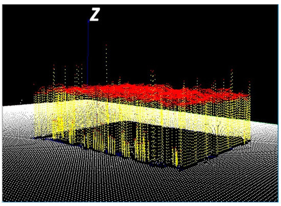
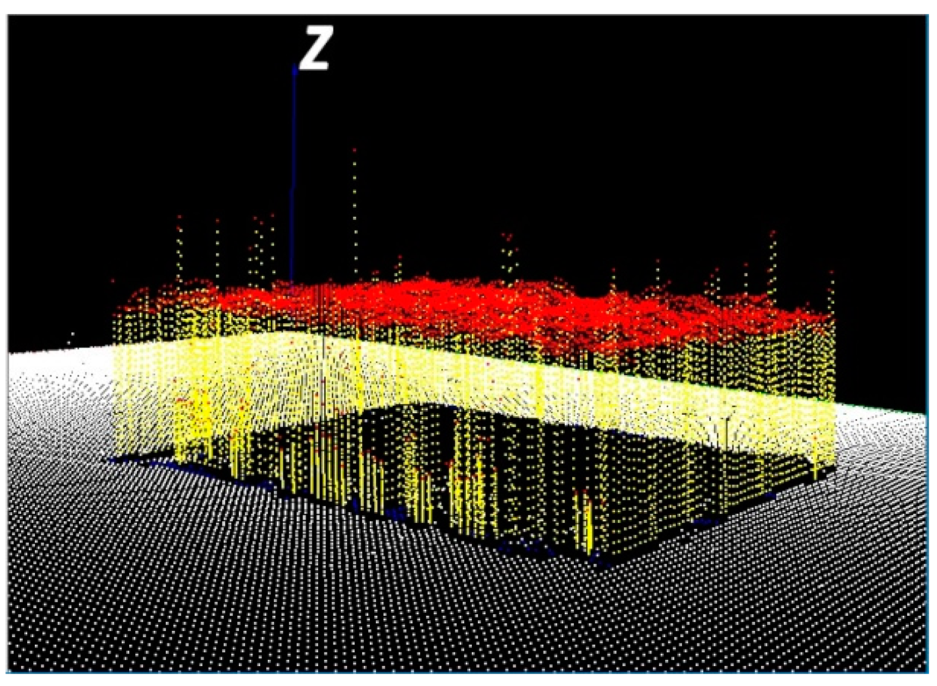
Nowadays, optical surface profilometry has a broad range of applications, especially for the measurement of critical dimensions and the process automation of industrial workpieces. Three-dimensional surface profilometry is a crucial technology for the quality inspection of various manufacturing processes. However, one of the significant challenges in digital image correlation (DIC)-based profilometry is surface edge detection. Figure 1 shows the depth image of a square box with four surface line edges detected using traditional DIC. As can be seen, the measurement and reconstruction of the edges are far from accurate [1], indicating that the current DIC-based approach cannot accurately detect and reconstruct 3D surface edges. Such inaccuracy also suggests that pattern cross-correlation in DIC is not effective in determining the geometric information of surface edges. Conventional DIC-based surface profilometry often suffers poor accuracy due to noisy data along surface edges.
Figure 1.
Depth image of a square box with four line edges detected using the traditional Digital image correlation (DIC) method.
The commonly used structured light projection techniques include phase-shifting, structured-code, random-speckle, and digital image correlation (DIC) detection approaches. This article focuses on the 3D DIC-based random-speckle processing method, which is an efficient full-field on-shot measurement technique, and can provide absolute depth information. To achieve single-exposure full-field surface profilometry, the 3D DIC-based random-speckle methodology projects random laser speckles on the tested surface and evaluates absolute depth through correlating the captured image with pre-calibrated reference images [2,3]. In such a process, a set of image blocks with unique deformed random-speckle patterns is acquired to correlate mathematically with the images in the pre-calibrated database. In random-speckle profilometry, small lens apertures are often employed to obtain high depth-of-field (DOF) measurements. However, both depth resolution and accuracy are often undermined due to increased depth range.
For precise 3D absolute measurement, a fundamental problem is the random variation of light intensity in each small sub-area of the projected random-speckle image without a repeating pattern. Current studies on DIC detection accuracy aim at the optimization of measuring parameters, enhanced quality of random-speckle patterns, improvement in speckle-generating methods, and speckle image-processing algorithms. Measuring parameters including the size, shape, and contrast of laser speckles, as well as the correlation subset size, are closely related to speckle quality [4,5]. In general, a larger speckle size and correlation subset can obtain a higher contrast in speckle quality which can diminish the measured noise but increase the calculation time in DIC. Some speckle quality indexes were developed to determine the quality of a speckle pattern and the optimal subset size for accurate and efficient DIC operation [6,7]. In 2013, Crammond pointed out potential limitations on contrast-type criteria that fail to provide a reliable indication for the randomness of the speckle pattern [8]. Speckle size distribution and speckle shapes are regarded as important local unique features for achieving a steady DIC. For better accuracy of 3D DIC-based measurements, different strategies such as ground-glass laser emission, white-paint spray, or computer simulation have been developed to generate random image features to enhance the uniqueness of speckle patterns [9,10,11]. Moreover, some speckle image-processing algorithms have been proposed to optimize the signal-to-noise ratio in cross-correlation. Some approaches, utilizing manifold reference image sets or through implementing correlation peak detection, overcome discontinuous displacement with a split subset [12,13]. Other methods use either adaptive binarization or reliable-point matching to enhance the image contrast to improving measurement accuracy [14]. Furthermore, a feature speckle was extracted by considering statistical binary characteristics, and a graphical model-based scheme was developed for refining disparity maps to enhance measurement accuracy [15]. The accurate reconstruction of sharp surface edges has been achieved using an innovative edge detection algorithm with structured illumination microscopy (SIM) [16]. Nevertheless, 3D surface boundary edge detection remains a major challenge for DIC-based surface measurement. An initial concept was developed to improve the accuracy of the critical dimension by detecting surface edges [17]. However, the full algorithm for accurate edge detection has not yet been developed, nor has the feasibility of current measurement approaches in industrial applications been carefully evaluated. In view of this, a new speckle image-processing algorithm that uses a boundary subset and a corner subset for accurate reconstruction of surface boundary edges was developed, and its applicability to measuring industrial objects was assessed.
2. Methodology of the Random-Speckle Optical Detection and Processing Algorithm
2.1. Principle of Digital Imaging Correlation (DIC)
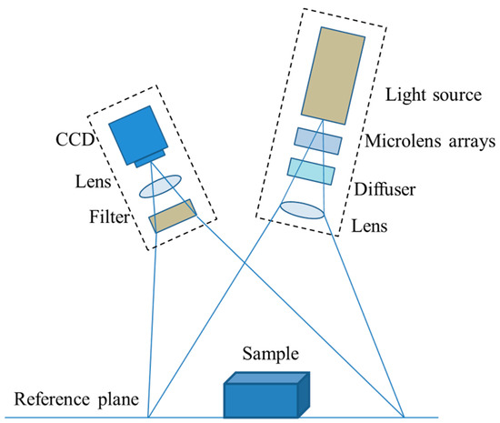
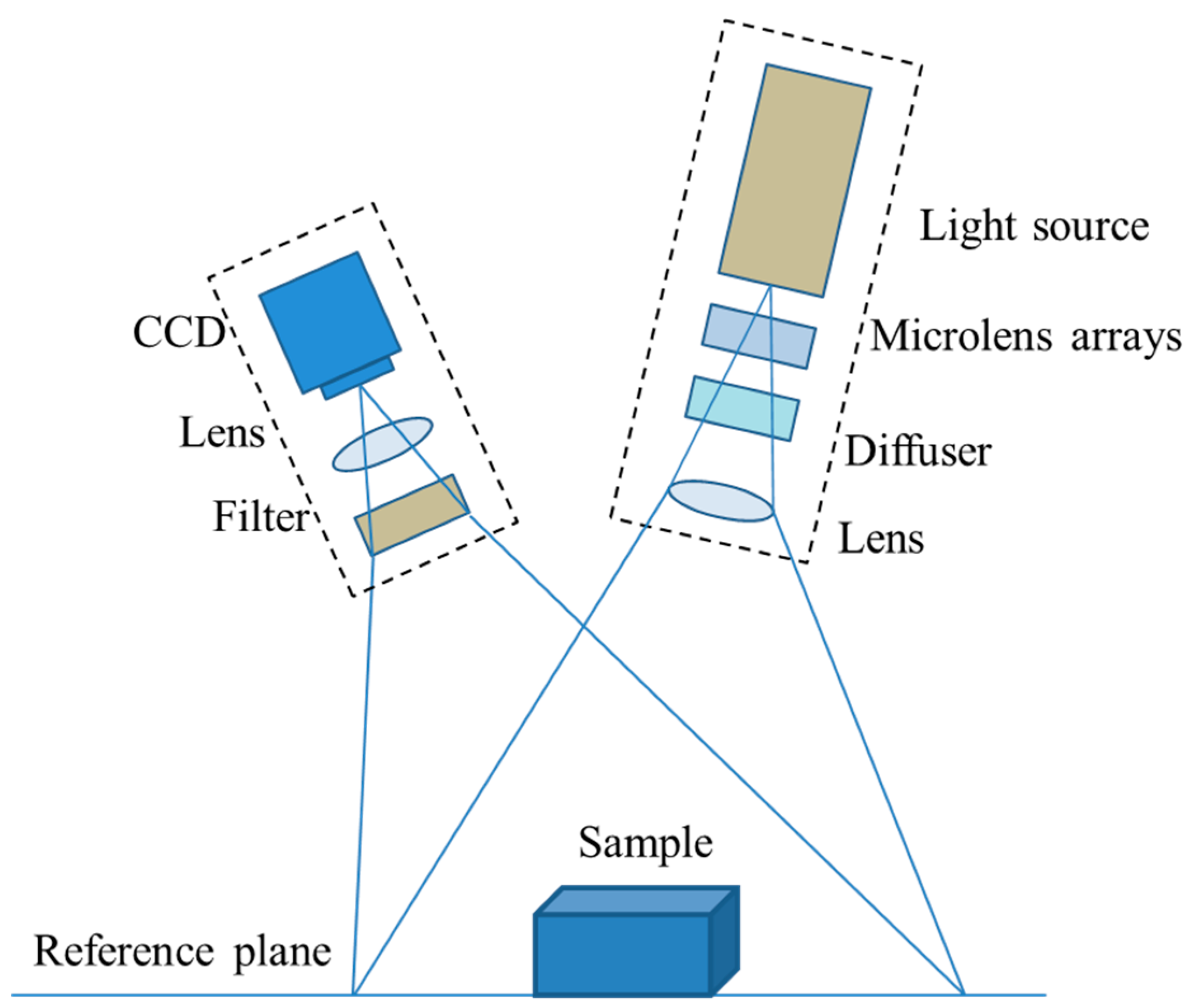
The laser triangulation principle with random-speckle projection is commonly used for the depth detection of 3D tested surface. Optical elements for generating laser random-speckles include an infrared laser, micro-lens arrays, and a diffuser. Figure 2 shows the optical configuration of the 3D surface profilometry, in which a near-infrared (NIR) laser is used for random-speckle projection. An imaging sensor is employed to detect the shifted phase corresponding to the difference in optical paths formed by the detected surface depth.
Figure 2.
Optical configuration for 3D surface profilometry.
To generate random speckles of various intensities without a repeating pattern, the NIR laser was used as a light source to reduce interference from environmental light. A large grit ground glass served as a diffuser to produce high-contrast grey-level patterns, while a low dark current charge-coupled device (CCD) camera captured the correct pixel intensity.
The DIC principle involves cross-correlating the surface depth detected using a deformed speckle image with the corresponding depth of the reference image in the stored database. Each random-speckle image is unique in its database; hence, the deformed pattern with a specific depth can be matched with its reference image. The surface depth of each image block is thus transformed into the surface depth of the object by triangulation transformation.
2.2. Normalized Cross-Correlation (NCC) for Edge Detection
The normalized cross-correlation coefficient can be defined in Equation (1) [17,18] and is commonly taken as a matching index for the correlation between the reference image subset and the measured image subset.
where , , H is the corresponding height of the reference image, t is the duration of time after the reference image is calibrated, is the width of the subset, and is the height of the subset.
Obviously, the subset size is an important parameter for best cross-correlation in terms of both measurement accuracy and efficiency. The optimal size depends strongly on the image contrast uniqueness of the speckle pattern. In general, the more unique the pattern is, the smaller the subset size required to obtain matching accuracy. Therefore, the uniqueness of the speckle pattern is first determined through cross-correlation between subset images; and a suitable subset window size is established by evaluating the uniqueness of the subset image at various locations of the reference speckle image.
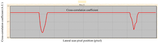
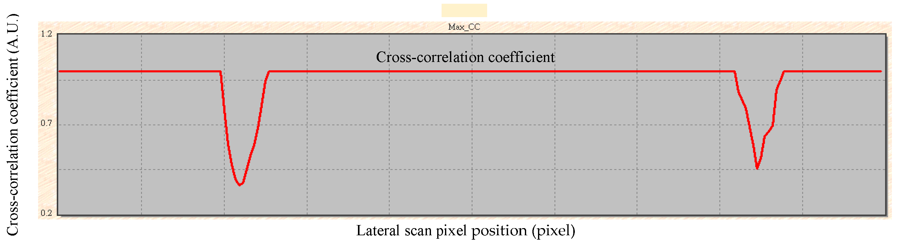
Traditional cross-correlation in DIC involves matching two entire image subsets in both the reference and measured sets. However, this is adequate only for a continuous surface with no contour jump. When there exists a discontinuous surface edge, subset pattern matching between the reference template and the measured image can no longer succeed because the subset random-speckle pattern, under such circumstances, is projected on both sides of the detected surface jump (or edge) with a step-height difference between the projected images. Figure 3 shows how a continuous surface edge is measured by detecting the peak of the cross-correlation coefficient curve along the scanning axis. As can be seen, a lateral scan along the surface edge reveals a decline of the curve to a local minimum, indicating a decrease in cross-correlation between the reference subset image and the measured subset image, followed by a rise back to its original level.
Figure 3.
Cross-correlation coefficient curve along the lateral scan axis on a rectangular gauge block with two surface edges.
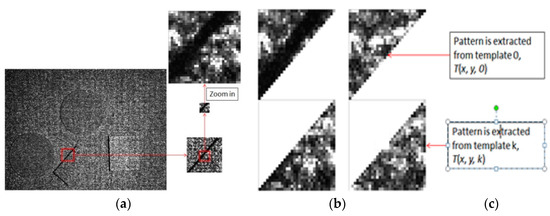
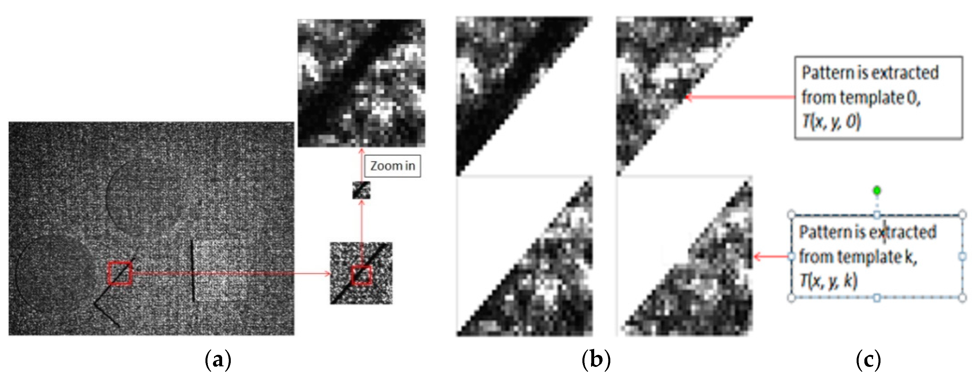
When measuring a geometrically discontinuous surface edge, the measured subset image pattern on the detected edge is affected by edge light diffraction. The measured image pattern comprises two sub-patterns represented by the two split surfaces on either side of the measured edge. Figure 4 shows an example of the above scenario. The measured image pattern marked by a red square comprises the top-left triangular region, the light diffracted region, and the bottom-right triangular region. More importantly, the two triangular subset images correspond to their own reference heights, which represent the measured top-left and bottom-right surface contour regions, respectively.
Figure 4.
Measured subset image pattern formed by a surface contour edge: (a) measured image of multi objects; (b) a red square indicating measured subset image pattern along a titling contour edge, which comprises the top-left triangular region, the light diffracted region, and the bottom-right triangular region; and (c) two triangular subset images corresponding to their own reference heights.
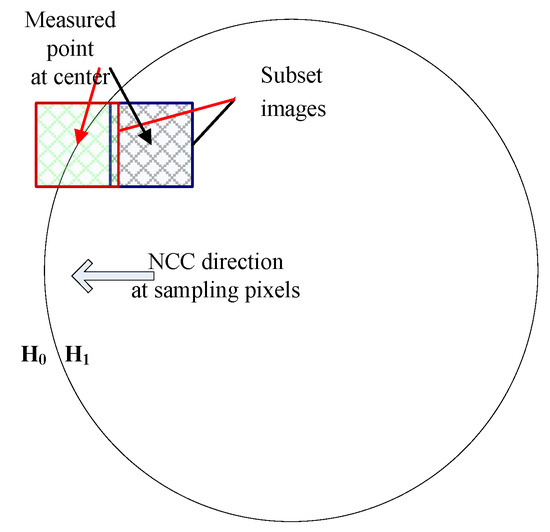
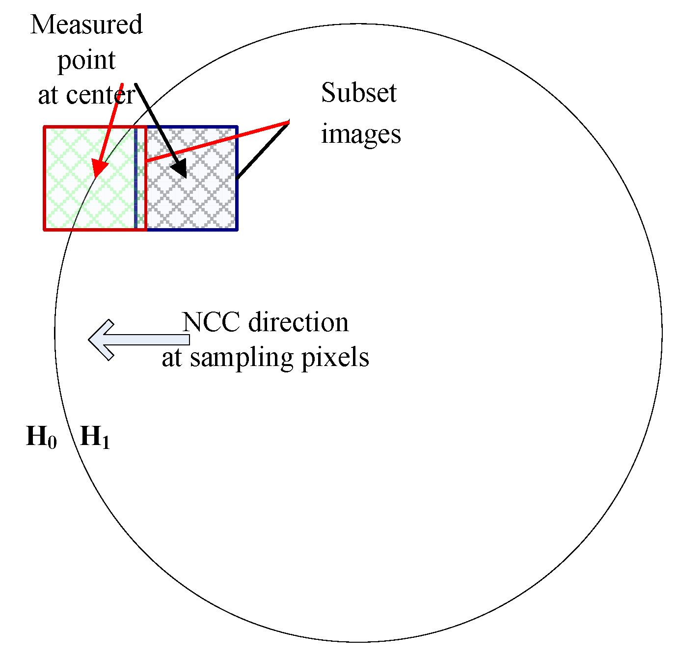
Next, the edge detection accuracy of two typical subsets was evaluated. Figure 5 shows two typical subsets formed when the template scans along a surface contour edge. The blue square represents a subset image acquired from a continuous surface contour, while the red square shows a subset image scanned on a discontinuous surface with an edge.
Figure 5.
Typical subsets formed when the template scans on a surface with an edge.
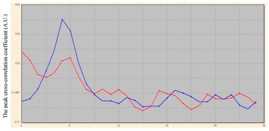
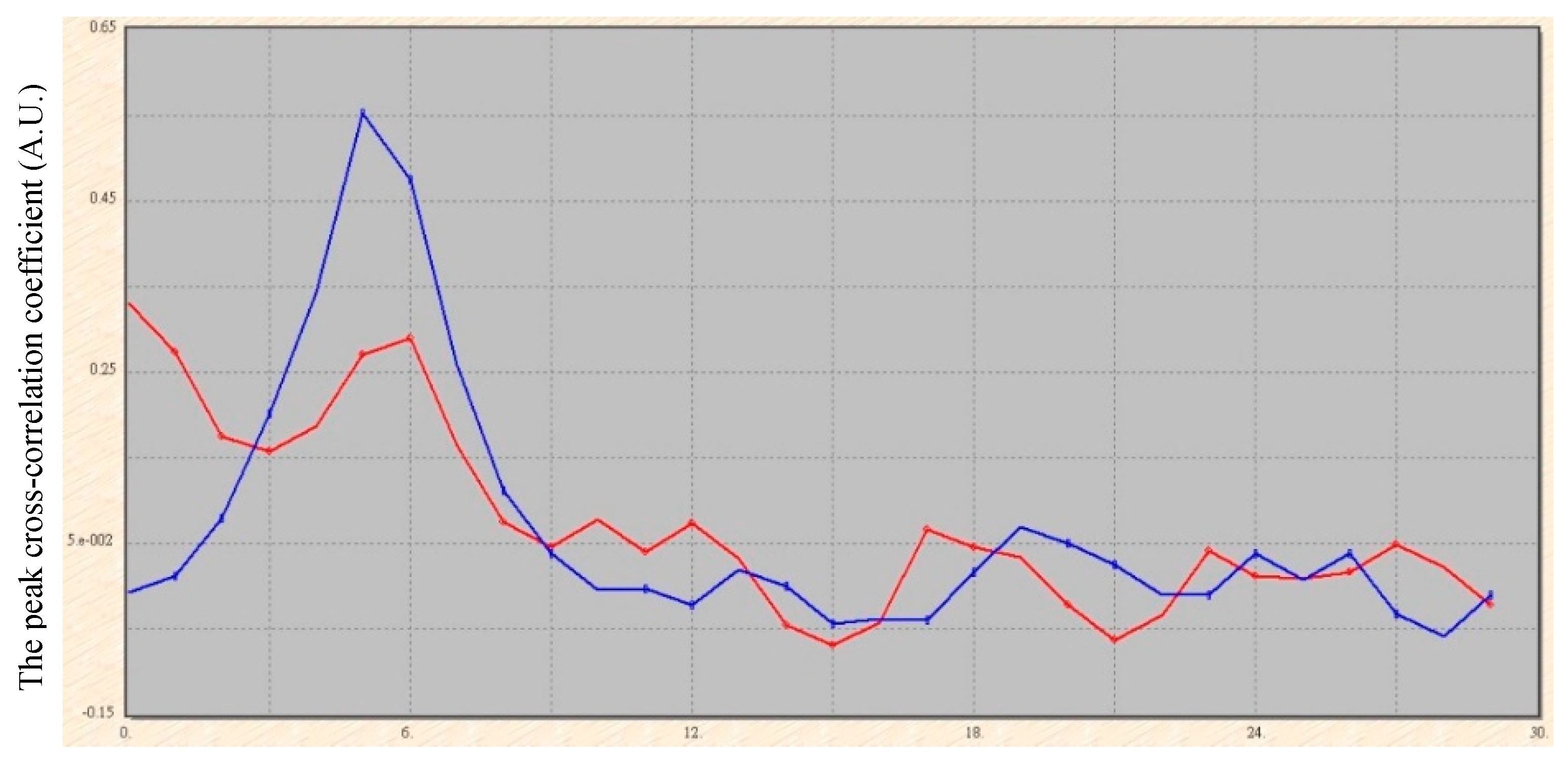
Figure 6 shows the two normalized cross-correlation coefficient curves acquired when both blue and red subset images are matched with their corresponding reference templates. It is apparent that the red subset image scanned past an edge did not possess the clear peak that is essential for accurate depth detection. To resolve this problem, two new subsets, namely boundary and corner subsets, were proposed as described in the following section.
Figure 6.
Two normalized cross-correlation coefficient curves acquired when both the blue and red subset images were matched with their corresponding reference templates.
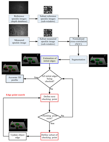
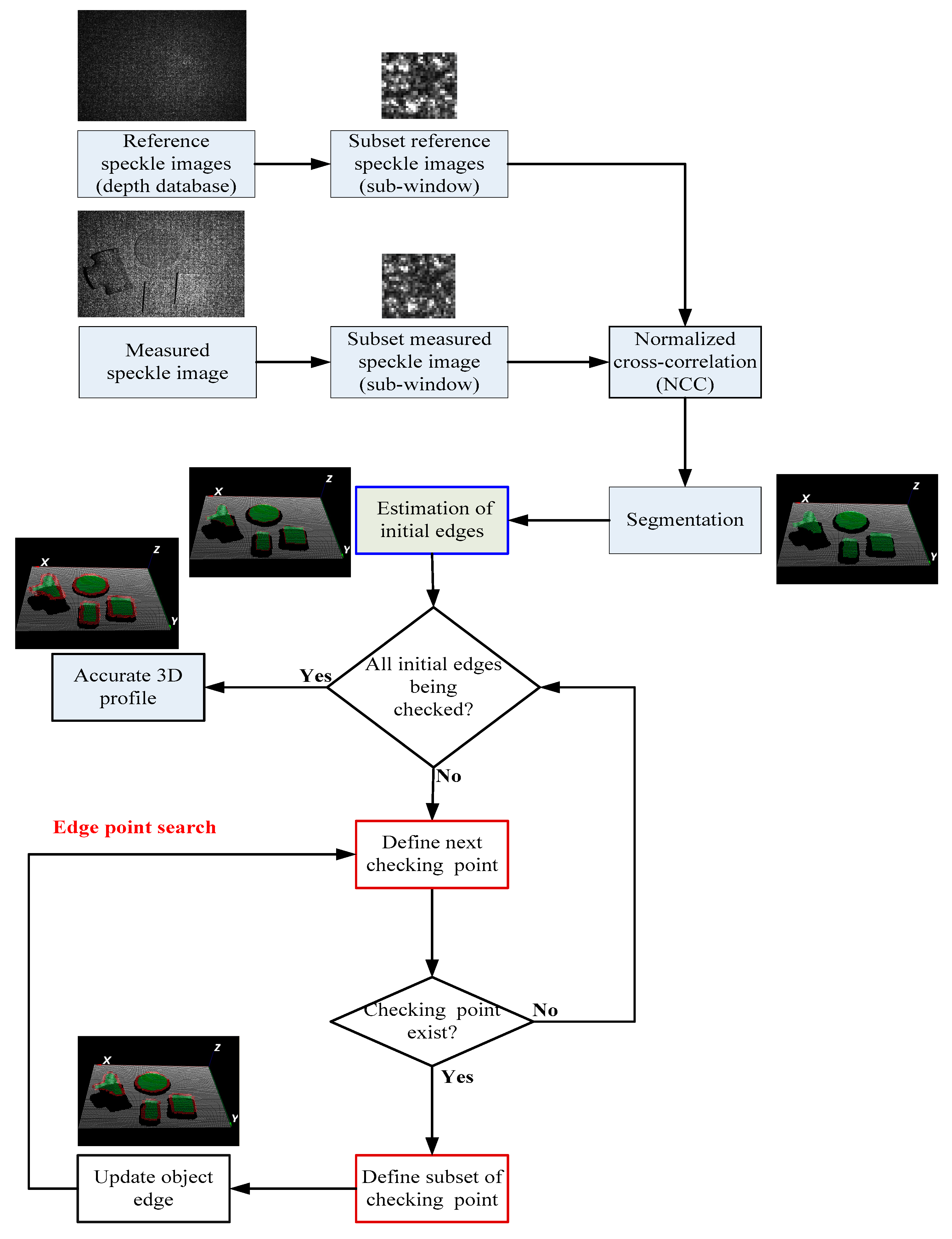
To achieve precise contour measurements for an object with discontinuous surface features, a novel 3D edge detection approach was proposed. The related procedures are presented in the flowchart shown in Figure 7. Algorithm 1 describes the steps and conditions required. First, a digital image-normalized cross-correlation was performed on the full-field detected speckle image to generate an initial 3D point cloud. In Step 2, object segmentation was applied to the initial 3D point cloud for the detection of object surface boundaries and contour edges. Following this, the mean and standard deviation of the correlation coefficient of object points were calculated and used as indexes for edge searching. Furthermore, the edge point was estimated using the geometry relationship of each measured point as the detection center with its eight neighboring points. In Step 5, the boundary search point was defined as a non-edge point located adjacent to an edge point. The subset type of search NCC was determined by the geometry relationship of the inspection point and its eight neighboring points. A new edge point was detected and updated when the correlation coefficient of the search portion exceeded the pre-defined edge point threshold. The algorithm is detailed in Section 2.3, Section 2.4 and Section 2.5.
Figure 7.
Flowchart of the developed approach.
| Algorithm 1 | |
| Input: Standard-height template database T and measured speckle image R. | |
| Output: 3D profiles of objects | |
| 1 | Implement normalized cross-correlation digital image correlation (NCC DIC) to generate point clouds. |
| 2 | Segment point clouds into individual measured objects. |
| 3 | Calculate the mean and standard deviation of the correlation coefficient of the measured point and use the mean as the threshold in the following search. |
| 4 | Estimate the edge boundary of each measured point using the geometry relationship of the point with its eight neighboring points. |
| 5 | Edge point search: |
| 5.1 | Define the next inspection point according to the relationship of the point with its neighbors. |
| 5.2 | Define the subset of inspection points according to the relationships of the points with their neighbors. |
| 5.3 | Perform NCC between the subset of inspection points and the corresponding standard-height templates. |
| 5.4 | Update the edge as an inspection point if its NCC result is larger than the current one. |
| 6 | Stop the edge point search when there is no more inspection points. |
2.3. Initial Edge Point
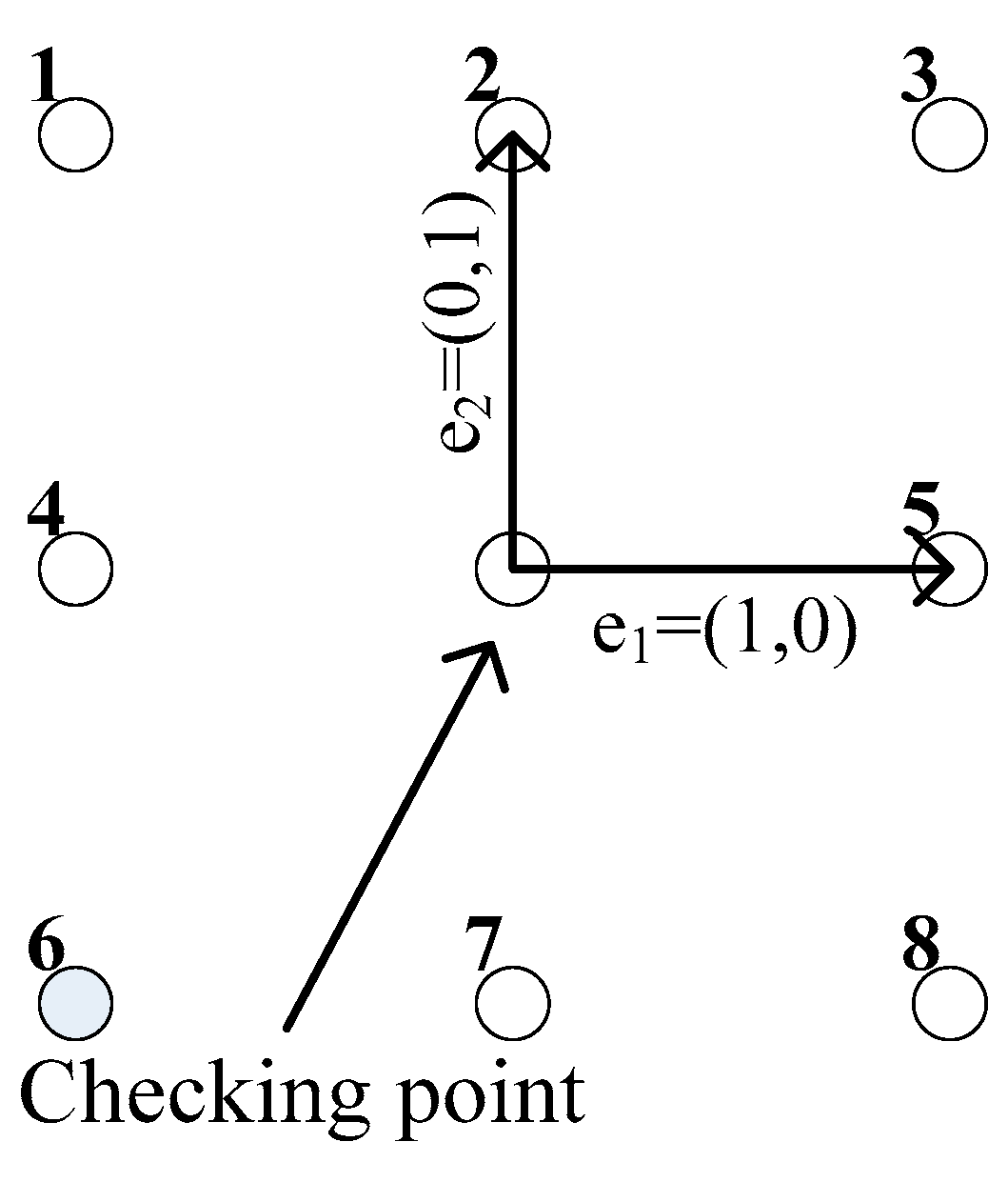
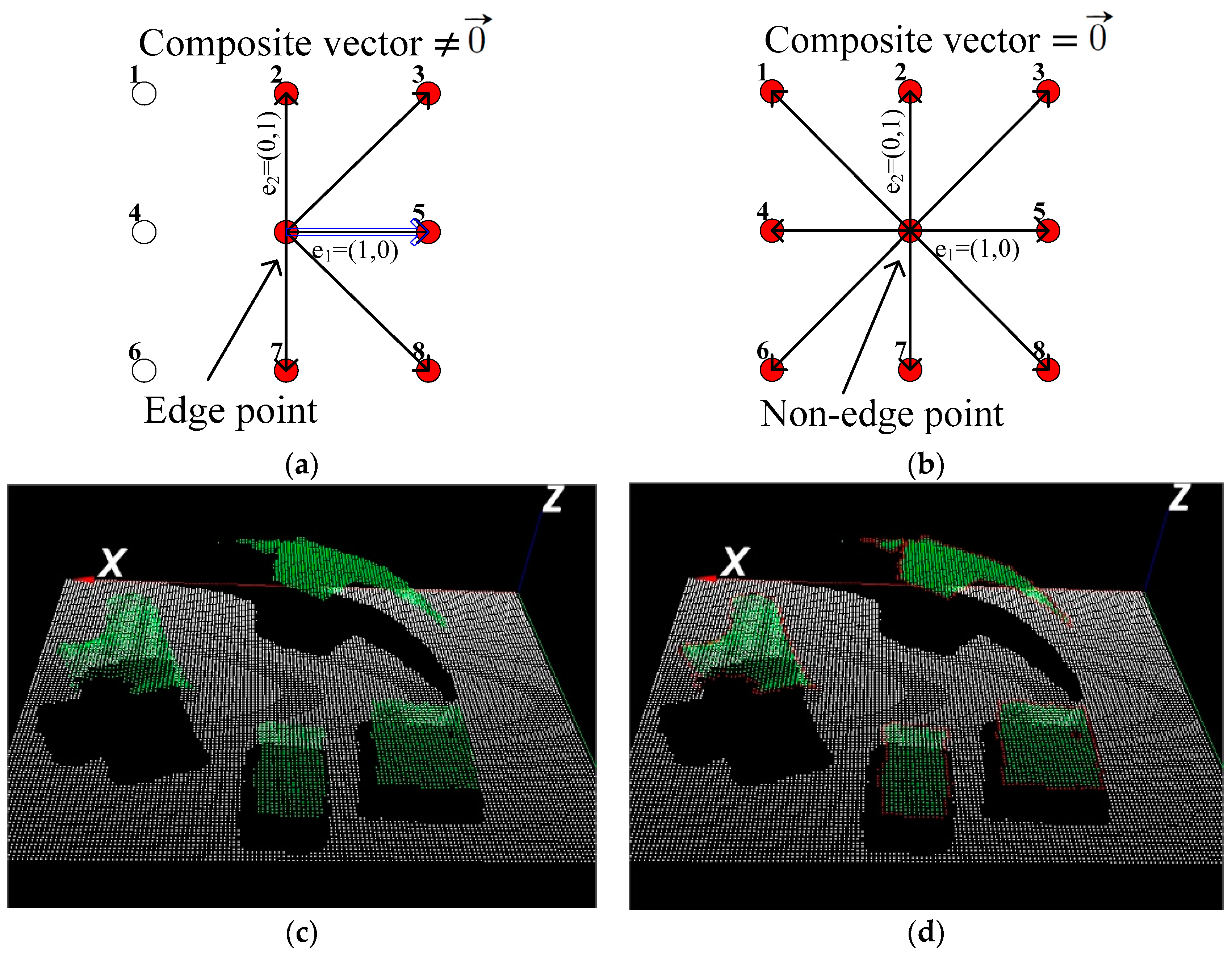
First, viewpoint-independent 3D object segmentation was performed to separate point clouds into individual objects and obtain the initial edges of each object [19]. The inspection point was defined as the origin of a Cartesian coordinate system with two vectors of unit length pointing along the x and y axis to its eight neighboring pixels, as shown in Figure 8.
Figure 8.
The Cartesian coordinate system of inspection points.
The vector comprises the standard basis vectors e1 and e2, as shown in Equation (2).
Where 1n and 2n are vector components of vn on the basis vectors.
Then, the composite vector of an inspection point is defined by Equation (3).
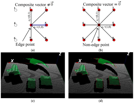
There exists a vector from the inspection point to each of its neighboring points, which are marked as red spots in Figure 9. An inspection point in this step was defined as an initial edge point if its composite vector is not a zero vector (shown as Figure 9a). In contrast, the composite vector of a non-edge point is a zero vector (shown as Figure 9b). The initial edge link was generated by enclosing all the neighboring initial edge points.
Figure 9.
Estimation of initial edge point: (a) edge point, (b) non-edge point, (c) an example of the measured point cloud, and (d) an initial edge link established for the example in (c).
2.4. Search Strategy for Accurate Edge Points
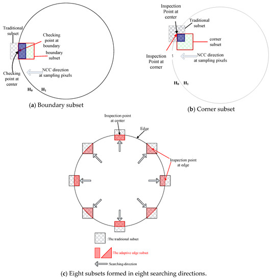
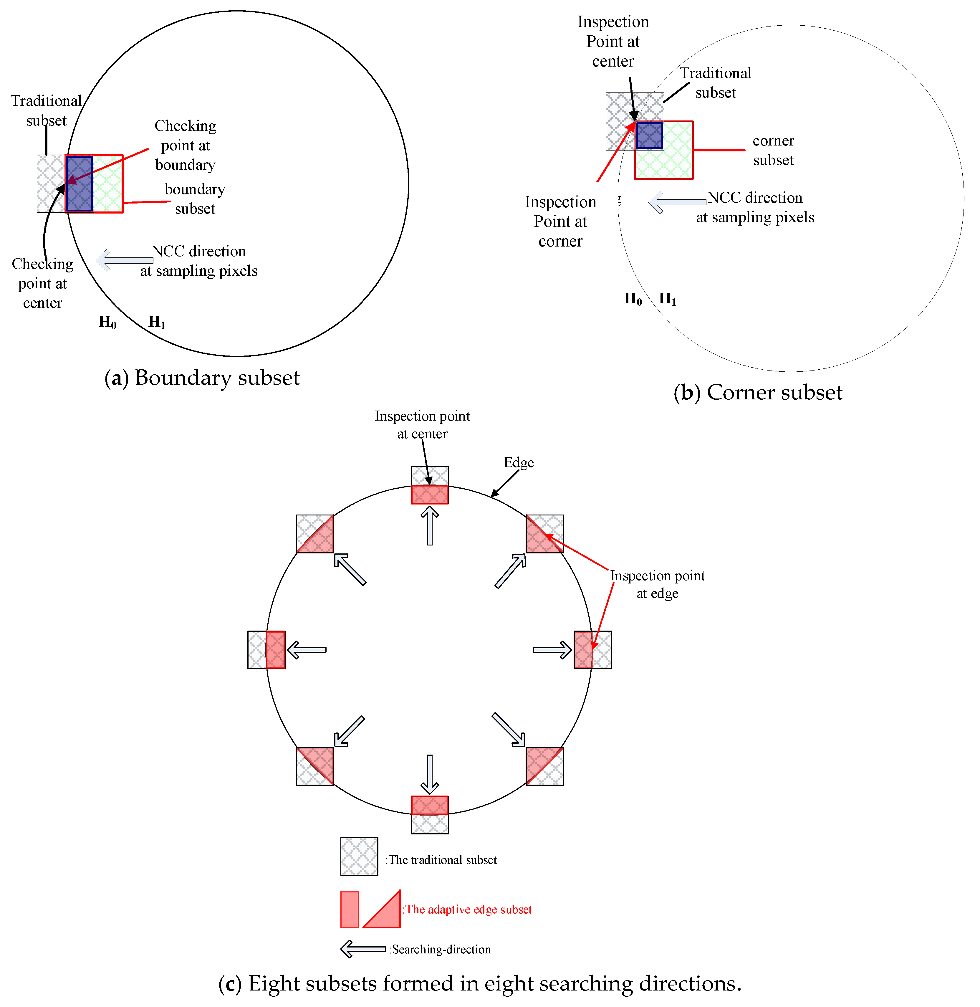
In view of the fact that the speckle pattern measured along a contour edge does not match the image in the reference template database, two new types of speckle subsets, namely boundary and corner subsets, were proposed to search the accurate edge points. The boundary subset had a condition that the split line was either of a horizontal or vertical boundary. Figure 10a shows the difference in edge detection between the proposed boundary subset and the traditional central subset when an inspection point was located on the contour edge. The overlapping region shown as a blue rectangle is the difference between the surface edge and the center of the boundary subset. Similarly, the corner subset had a condition that the split line is of a tilting boundary. Figure 10b shows the comparison between the corner subset and the traditional subset when an inspection point was located on the contour edge. The overlapping region shown as a blue square represents the potential difference in object edge detection. When the inspection point was scanned toward the eight directions shown in Figure 10c, eight speckle subsets could be formed either by the boundary subset or corner subset. More speckle subsets could be formed when more scanning directions were taken, for higher accuracy in the surface edge detection. In addition, the higher the scanning resolution, the more accurate the reconstruction of the object contour.
Figure 10.
Proposed speckle subsets for contour edge detection.
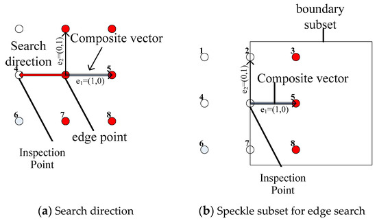
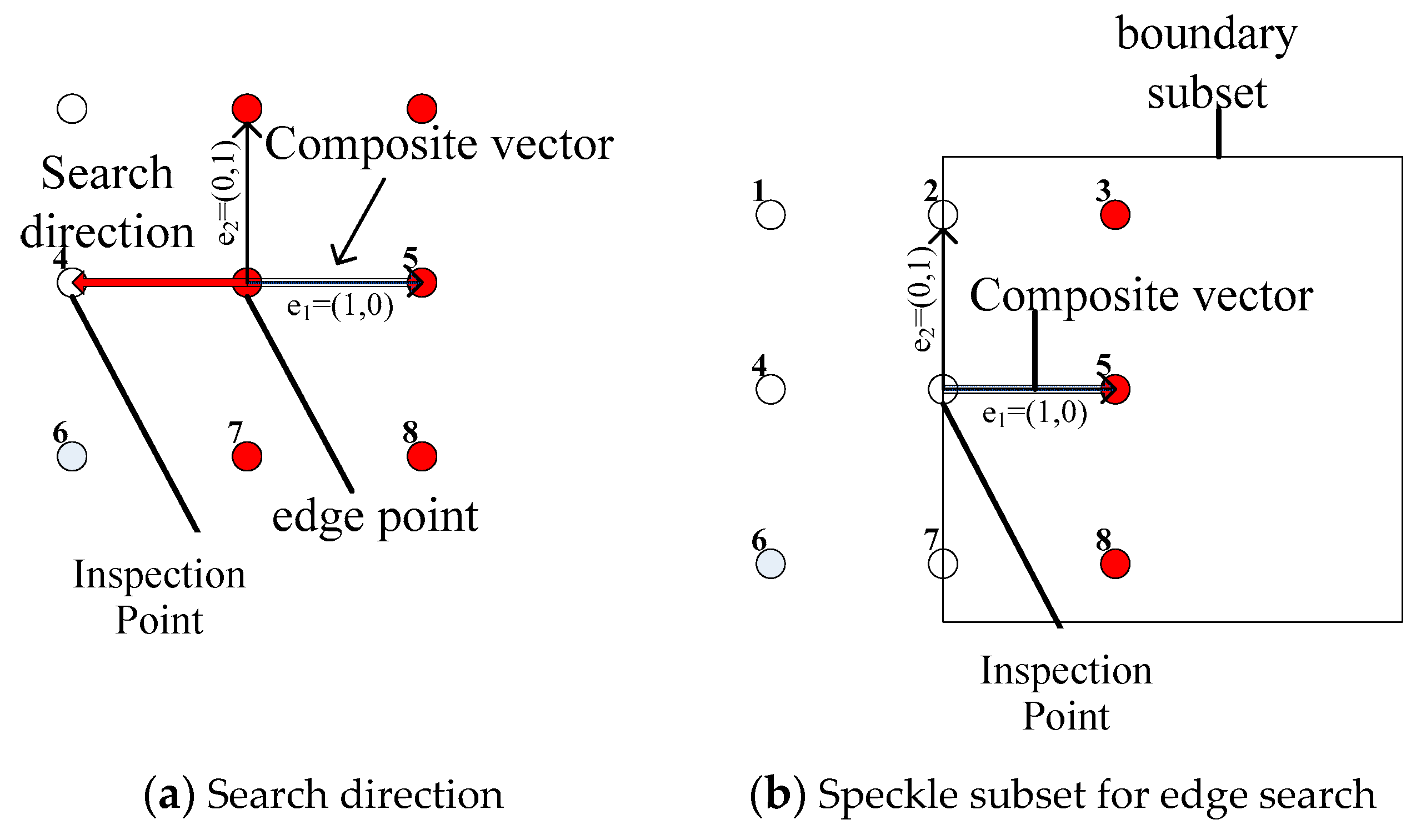
The search direction of the edge point was specified to be opposite to its composite vector, as shown in Figure 11a. When an inspection point was set along the search direction, the composite vector of the inspection point was calculated to determine the subset type for the edge point search. Figure 11b shows the boundary speckle subset to be defined for a horizontal or vertical search direction.
Figure 11.
Boundary subset for horizontal or vertical edge search.
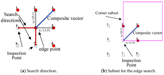
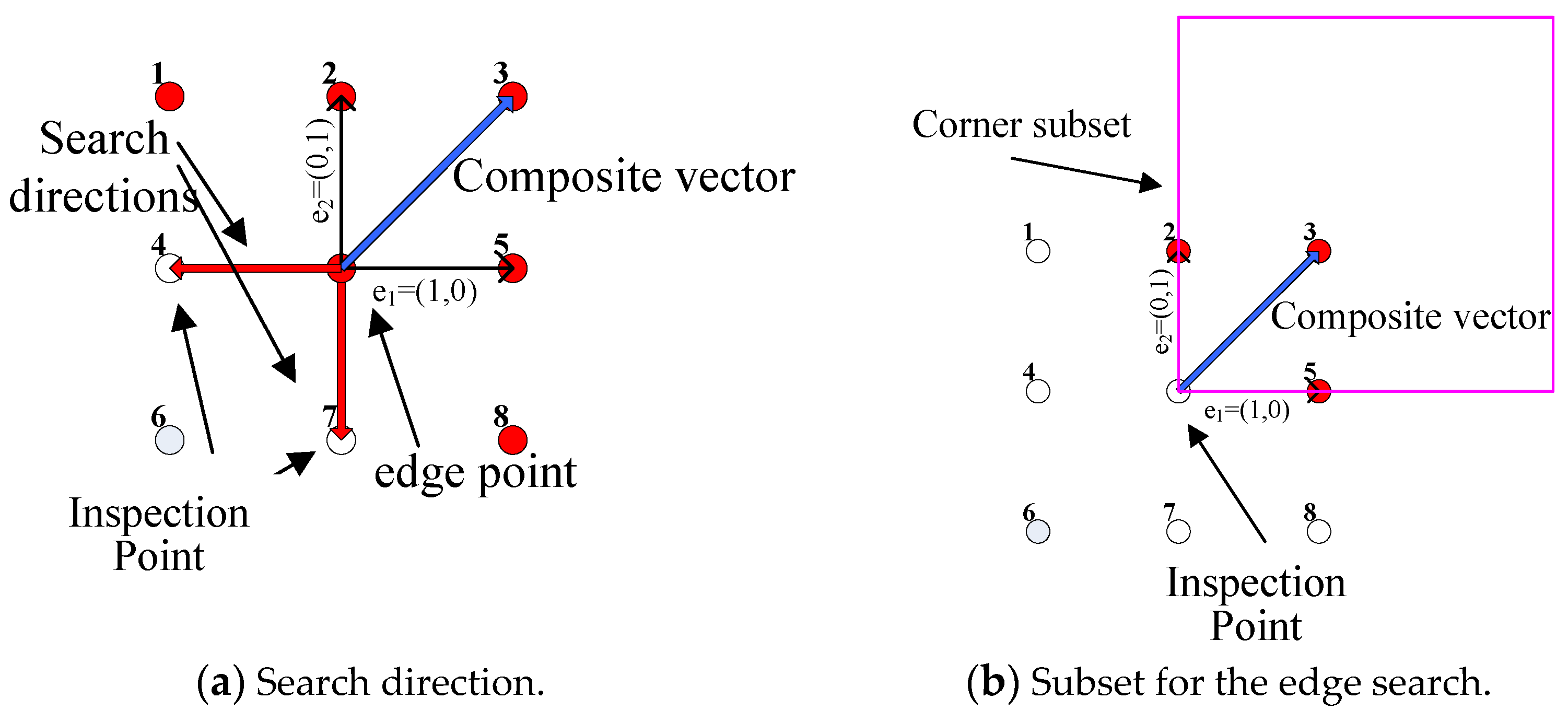
On the other hand, the corner subset was defined for a titling search direction. Figure 12a shows an inspection point set in the horizontal direction and another in the vertical direction. These two inspection points can define a corner subset for the edge search, as shown in Figure 12b.
Figure 12.
Corner subset for a titling edge search.
2.5. Criterion for Edge Detection
To ensure accurate edge detection, a threshold should be defined for the traditional NCC to filter low S/N coefficients from the point cloud. With a high-pass threshold for point filtration, the initial point cloud of the DIC measurement can provide a good basis for contour edge detection. As defined in Equation (4), an average correlation coefficient obtained by matching the reference image subset with its neighboring subset can generally provide a reliable threshold.
where c is the number of subsets in a column; r is the number of subsets in a row, and s is the sample pixel.
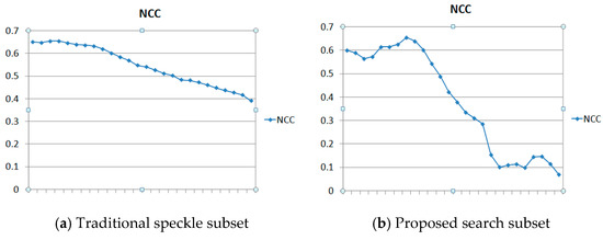
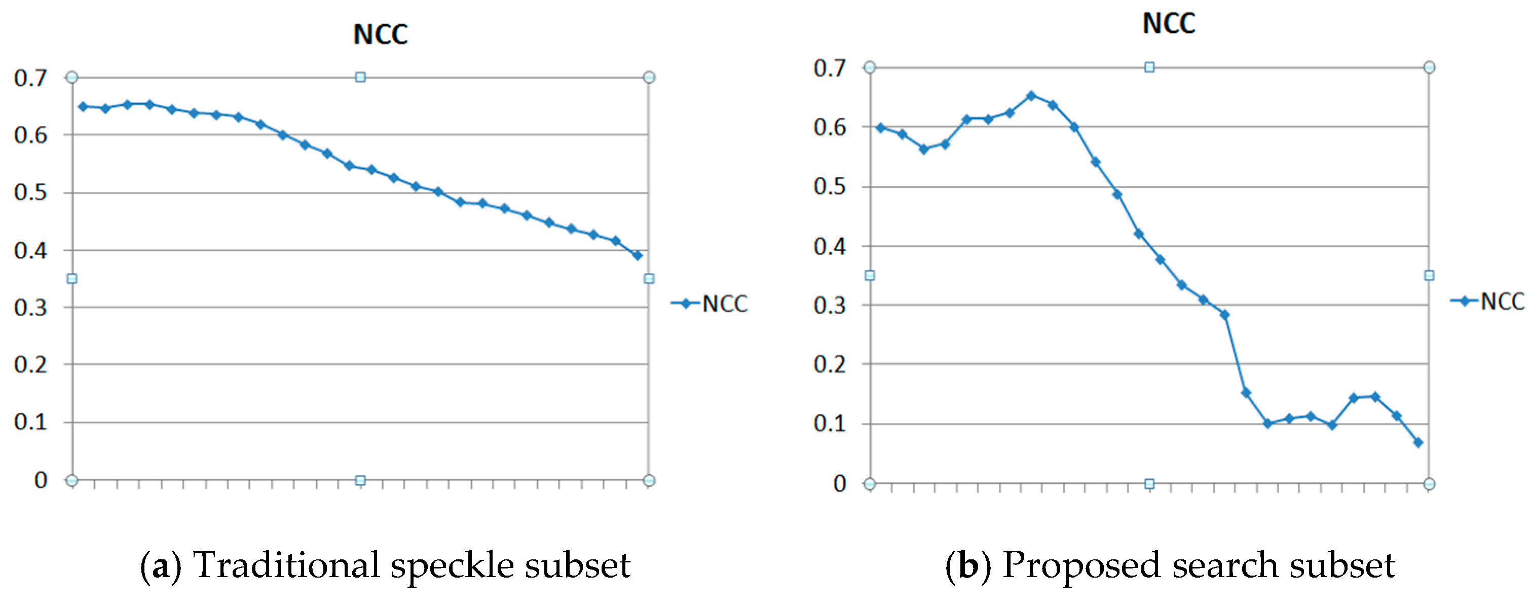
When performing NCC with the boundary or corner subset, the threshold required for reliable edge detection should be further determined by the NCC of the inspection subset. In the proposed approach, the variance of the normalized cross-correlation coefficients along the search direction was taken as the quality-filtering threshold. The correlation coefficient curves obtained from the edge detection process using the traditional subset and the proposed search subset are shown in Figure 13a,b, respectively. The size of the partial search subset was either or , depending on the search direction, where p is the number of sampling pixels in DIC. As can be seen, the normalized cross-correlation coefficient (NCCC) of the proposed search subset generally had a much higher sensitivity or slope than that of the traditional subset, because the subset speckle images of the proposed approach better matched their corresponding reference template images.
Figure 13.
Normalized cross-correlation coefficient (NCCC) curves.
3. Experimental Results and Accuracy Analyses
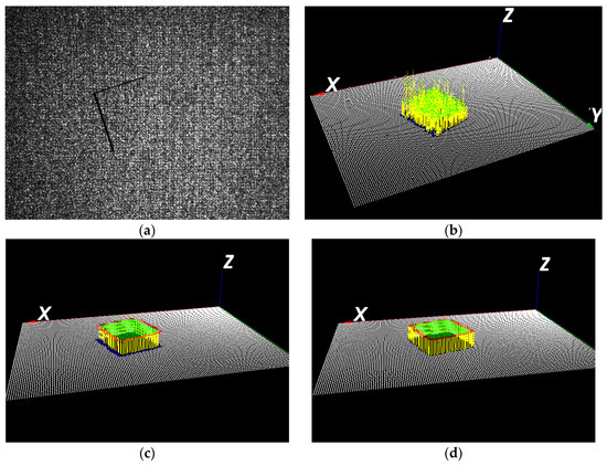
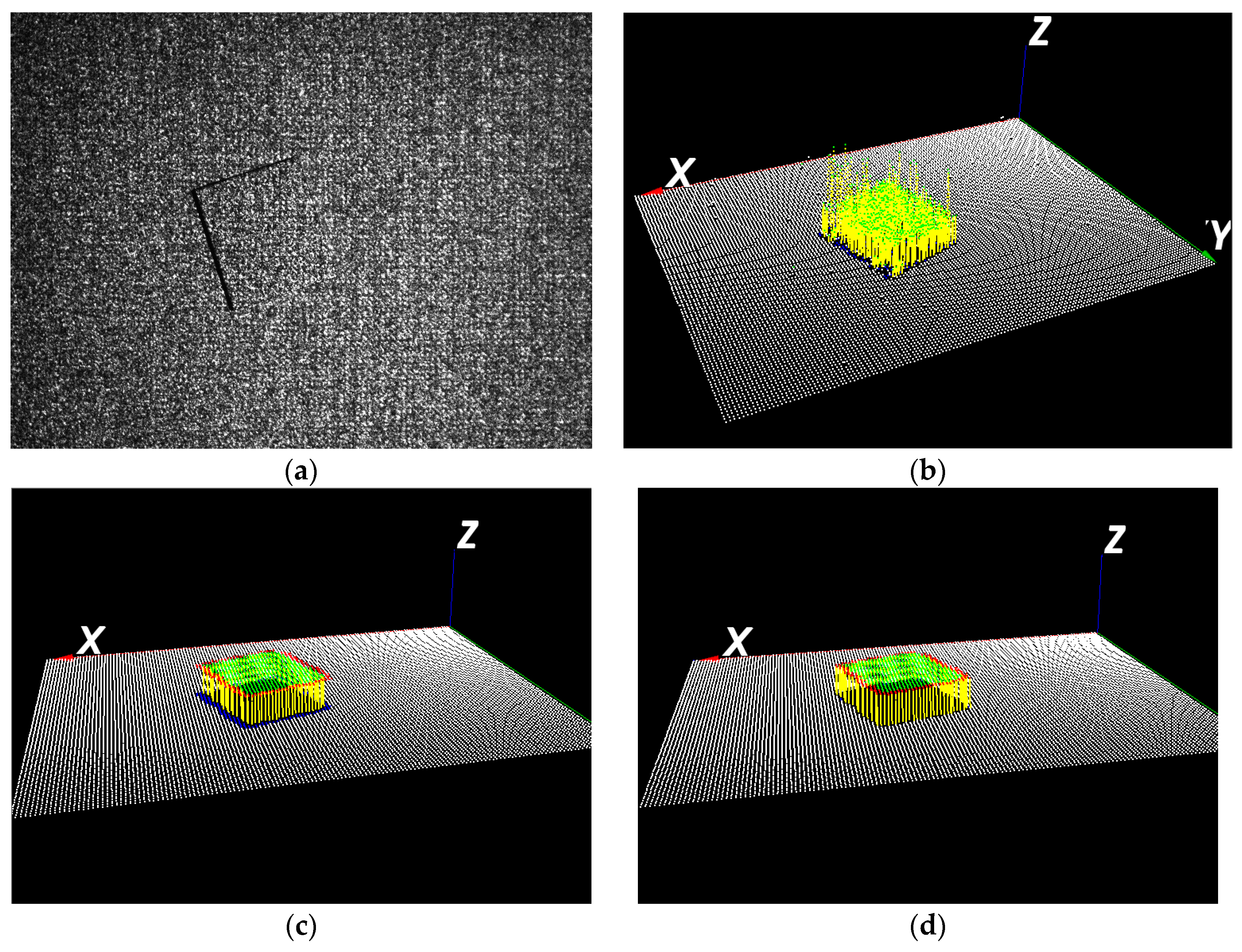
The proposed approach was developed using C++ on a personal computer with 3.2 Hz i5-4570 CPU and 4GB RAM. The 3D optical probe was incorporated with a three-axis scanning stage via Ethernet to detect speckle images. Three experiments with different setups were conducted using the probe and the developed approach to evaluate their effectiveness. First, to verify the accuracy of the developed approach, the reconstruction of a pre-calibrated gauge block with a step height of 9.000 mm and a coordinate measuring machine (CMM) calibrated circle target with a thickness of 5.000 mm was performed. Figure 14 shows the reconstruction results of the pre-calibrated gauge block. Repeated tests yielded improvements in the width-measuring error, standard deviation, and measurements of 1.06%, 315 μm and 22-fold, respectively; compared with the results obtained by the traditional DIC. Figure 14 also shows the improvement in accuracy obtained via 3D profiles and the corresponding measured speckle images with 2D edge detection of each step. The experimental results obtained verified the superiority of the developed approach to the traditional DIC for measuring surface contours, especially for edge measurement and reconstruction.
Figure 14.
Measurement results obtained using the proposed approach for reconstruction of the pre-calibrated gauge block: (a) speckle image; (b) 3D result measured using traditional DIC; (c) initial edge reconstruction using the proposed approach, in which some edge positions are still missing from its original object shape; and (d) 3D map reconstructed using the proposed edge detection method.
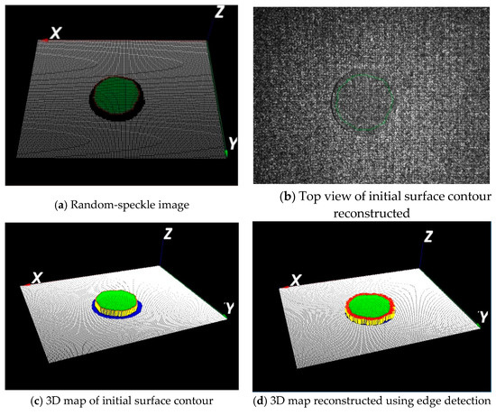
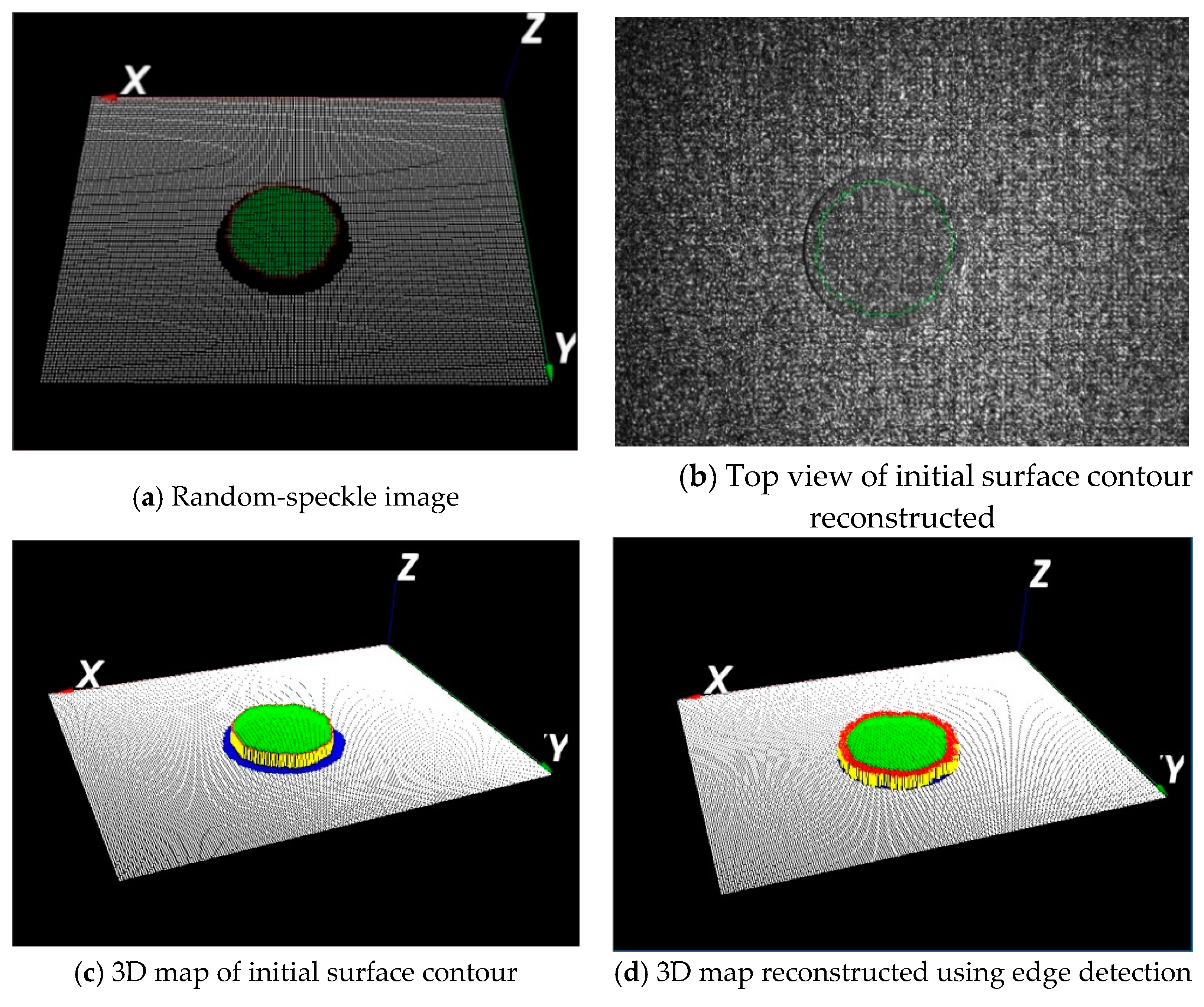
Figure 15 shows the reconstruction results of the pre-calibrated circle target. As can be seen, the measurement error was kept within 0.4% of the original diameter while the standard deviation was maintained at 267 μm. In comparison with traditional DIC, the developed approach achieved an 18-fold improvement in diameter measurement, indicating the superiority of the proposed method for critical dimension measurement. The comparison of different measurement results is shown in Table 1.
Figure 15.
Pre-calibrated circle target reconstructed with edge detection.
Table 1.
Comparison of measurement accuracy and improvement achieved by coordinate measuring machine (CMM), traditional digital image correlation (DIC) and, the developed approach.
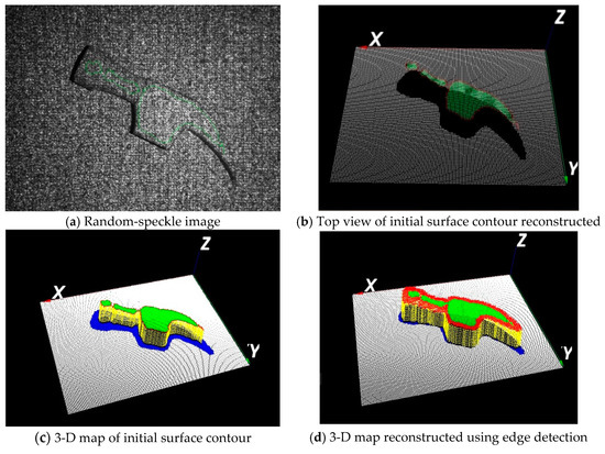
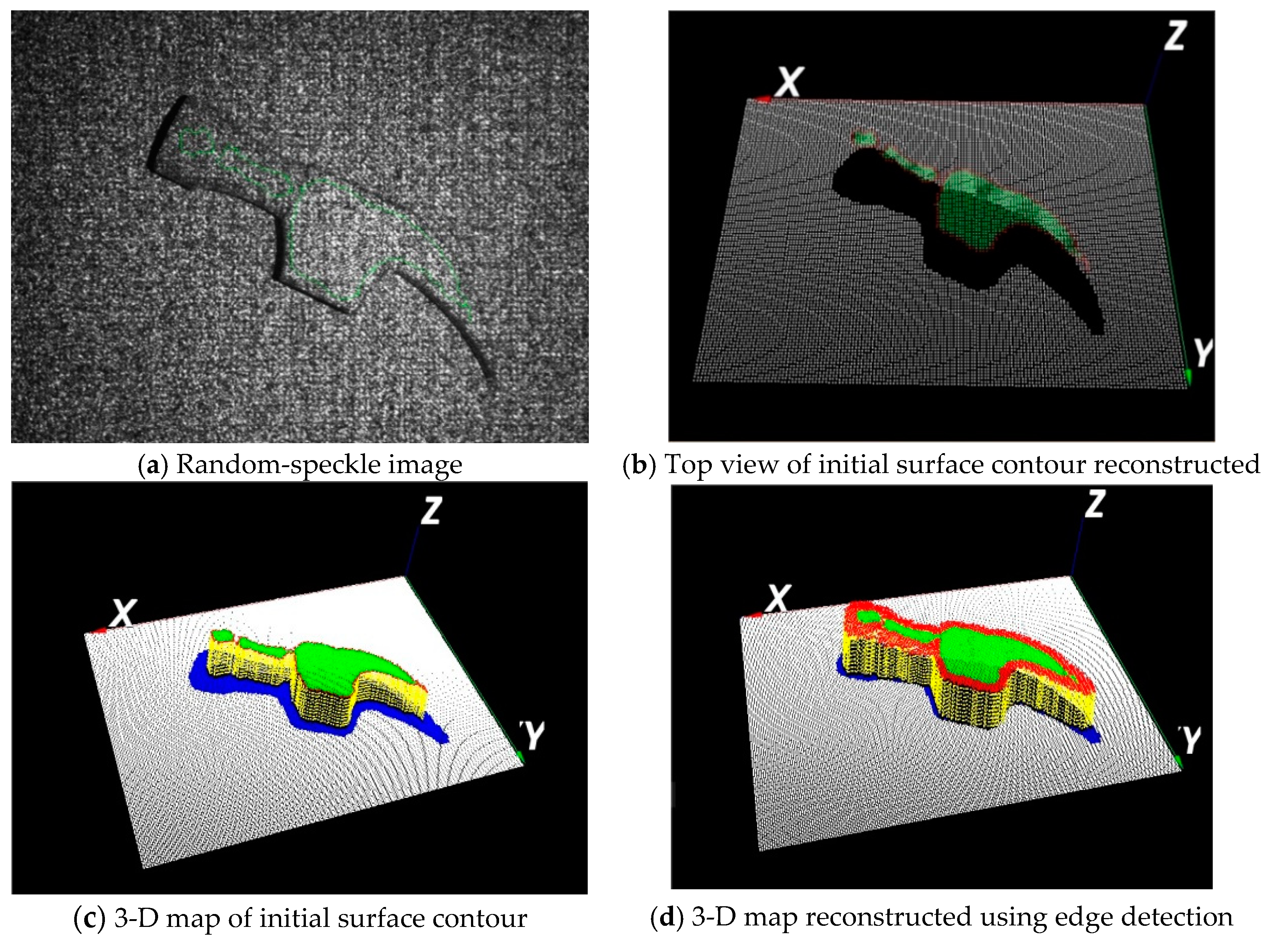
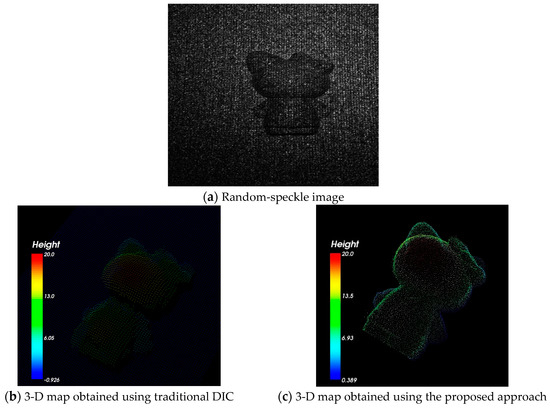
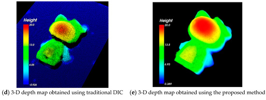
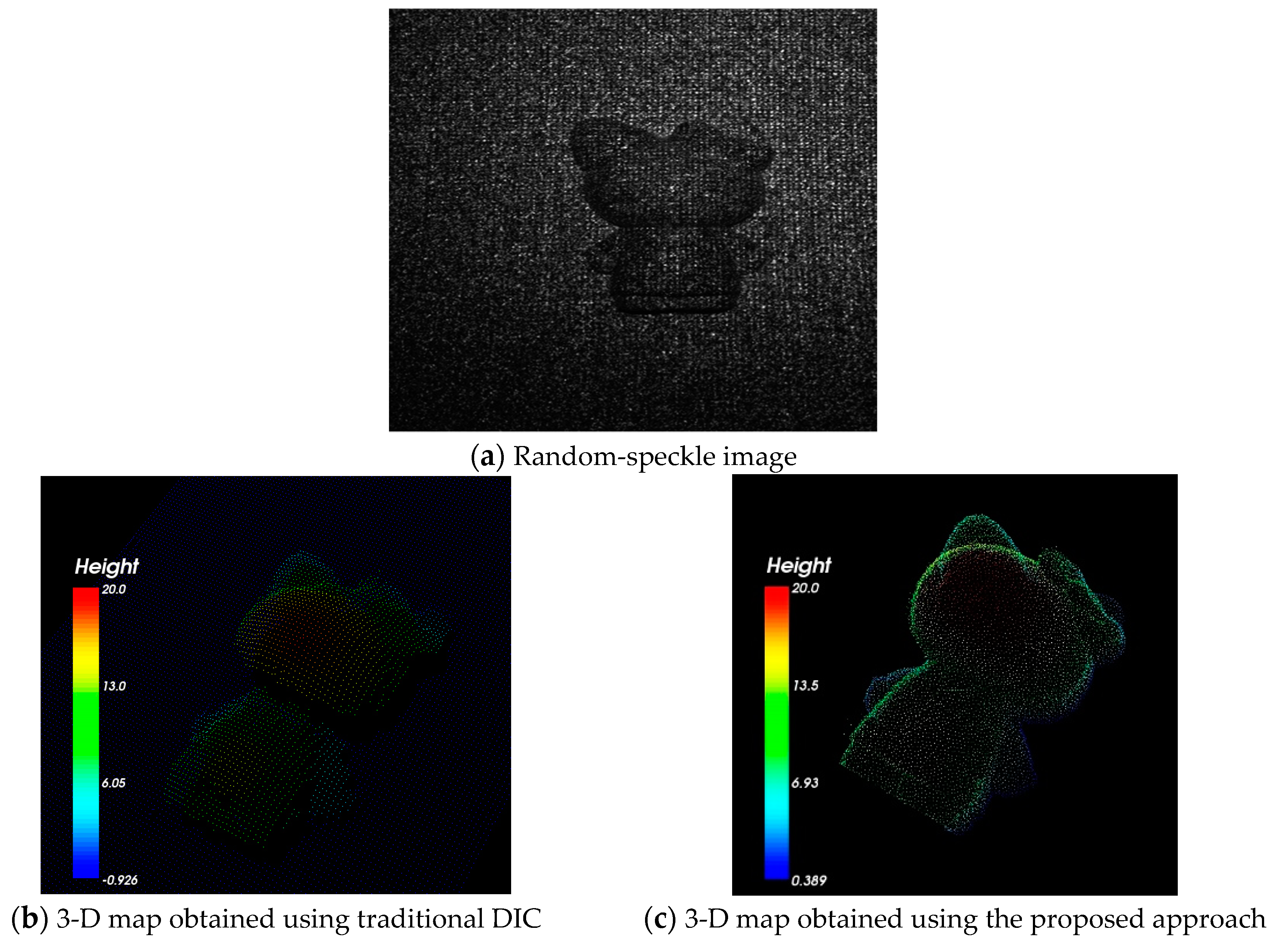
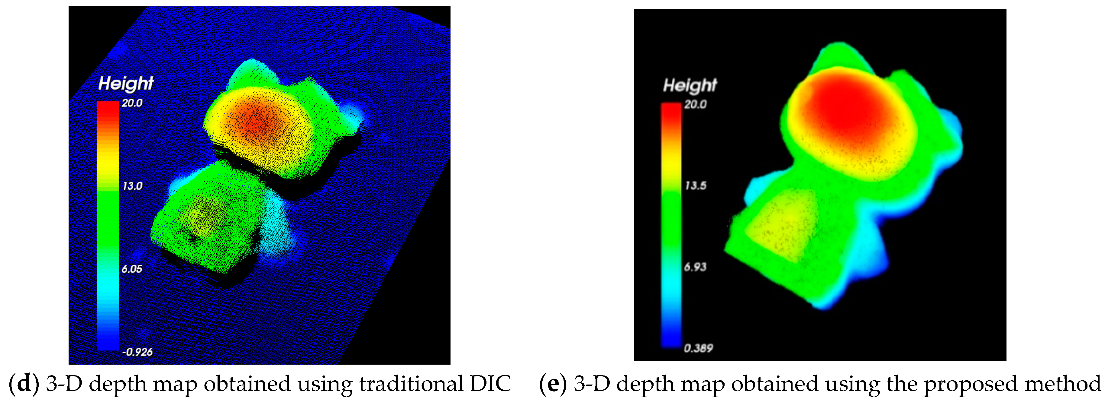
Edge detection was also performed on industrial workpieces to validate the feasibility of the developed method. Figure 16 shows the surface profile reconstruction of a 3D-printed hammer using the proposed approach, while Figure 17 compares the 3D map of a molding part obtained using both traditional DIC and the developed method. Experimental results and analyses revealed that traditional DIC has difficulty providing reliable edge information. The critical dimension could not be reconstructed accurately and conventional 2D image edge-detection technique had to be employed in conjunction to accomplish the measurement. The developed method achieved a 15-fold improvement in measurement, with error controlled within 1%.
Figure 16.
Reconstruction of a 3D-printed hammer using the proposed approach.
Figure 17.
Comparison of an industrial molding part reconstructed using DIC and the proposed approach.
4. Conclusions
In this research, a new surface edge detection approach was developed to achieve accurate surface edge measurement using various speckle DIC-based techniques. The developed algorithm has its basis in edge detection subsets and the variance of the normalized cross-correlation coefficients. Preliminary experimental results confirmed that the maximum measured error of the selected critical dimension was significantly reduced and controlled within 1% of the measuring range or size. The precision of the measurement, as one standard deviation, was also kept below 1.05% of the measuring range. Moreover, this study also verified that the subset size and speckle pattern contrast are crucial parameters influencing measurement precision.
Author Contributions
Conceptualization, L.-C.C.; Data curation, C.-W.L.; Formal analysis, L.-C.C.; Investigation, L.-C.C. and C.-W.L.; Methodology, L.-C.C.; Resources, L.-C.C.; Software, C.-W.L.; Supervision, L.-C.C.; Validation, L.-C.C.; Writing – original draft, C.-W.L.; Writing – review & editing, L.-C.C.
Conflicts of Interest
The authors declare no conflicts of interest.
References
- Andersen, M.R.; Jensen, T.; Lisouski, P.; Mortensen, A.K.; Hansen, M.K.; Gregersen, T.; Ahrendt, P. Kinect Depth Sensor Evaluation for Computer Vision Applications; Technical Report; Aarhus University: Aarhus, Denmark, 2012. [Google Scholar]
- McNeil, S.R.; Sutton, M.A.; Miao, Z.; Ma, J. Measurement of surface profile using digital image correlation. Exp. Mech. 1997, 37, 13–20. [Google Scholar] [CrossRef] [Scilit]
- Sjödahl, M.; Synnergren, P. Measurement of shape by using projected random patterns and temporal digital speckle photography. Appl. Opt. 1999, 38, 1990–1997. [Google Scholar] [CrossRef] [Scilit] [PubMed]
- Lecompte, D.; Smits, A.; Bossuyt, S. Quality assessment of speckle patterns for digital image correlation. Opt. Lasers Eng. 2006, 44, 1132–1145. [Google Scholar] [CrossRef] [Scilit]
- Schreier, H.W.; Sutton, M.A. Systematic errors in digital image correlation due to under matched subset shape functions. Exp. Mech. 2002, 42, 303–310. [Google Scholar] [CrossRef]
- Pan, B.; Lu, Z.; Xie, H. Mean intensity gradient: An effective global parameter for quality assessment of the speckle patterns used in digital image correlation. Opt. Lasers Eng. 2010, 48, 469–477. [Google Scholar] [CrossRef] [Scilit]
- Pan, B.; Xie, H.; Wang, Z.; Qian, K.; Wang, Z. Study on subset size selection in digital image correlation for speckle patterns. Opt. Express. 2008, 16, 7037–7048. [Google Scholar] [CrossRef] [Scilit]
- Crammond, G.; Boyd, S.W.; Dulieu-Barton, J.M. Speckle pattern quality assessment for digital image correlation. Opt. Lasers Eng. 2013, 51, 1368–1378. [Google Scholar] [CrossRef] [Scilit]
- García, J.; Zalevsky, Z. Three-dimensional mapping and range measurement by means of projected speckle patterns. Appl. Opt. 2008, 47, 3032–3040. [Google Scholar] [CrossRef] [Scilit] [PubMed]
- Pan, B.; Qian, K.; Xie, H.; Asundi, A. Two-dimensional digital image correlation for in-plane displacement and strain measurement: A review. Meas. Sci. Technol. 2009, 20, 062001. [Google Scholar] [CrossRef] [Scilit]
- Stoilov, G.; Kavardzhikov, V.; Pashkouleva, D. A comparative study of random patterns for digital image correlation. J. Theor. Appl. Mech. Pol. 2012, 42, 55–66. [Google Scholar] [CrossRef] [Scilit]
- Poissant, J.; Barthelat, F. A novel “subset splitting” procedure for digital image correlation on discontinuous displacement fields. Exp Mech. 2010, 50, 353–364. [Google Scholar] [CrossRef] [Scilit]
- Dai, H.; Su, X. Shape measurement by digital speckle temporal sequence correlation with digital light projector. Opt. Eng. 2001, 40, 793–800. [Google Scholar] [CrossRef] [Scilit]
- Wang, G.; Yin, X.; Pei, X.; Shi, C. Depth estimation for speckle projection system using progressive reliable points growing matching. Appl. Opt. 2013, 52, 516–524. [Google Scholar] [CrossRef] [Scilit] [PubMed]
- Yin, X.; Wang, G.; Shi, C.; Liao, Q. Efficient active depth sensing by laser speckle projection system. Opt. Eng. 2014, 53, 013105. [Google Scholar] [CrossRef] [Scilit]
- Le, M.-T.; Chen, L.-C.; Lin, C.-J. Reconstruction of accurate 3-D surfaces with sharp edges using digital structured light projection and multi-dimensional image fusion. Opt. Lasers Eng. 2017, 96, 17–34. [Google Scholar] [CrossRef] [Scilit]
- Chen, L.-C.; Liang, C.-W.; Tseng, H.-Y.; Lin, S.-T. Accurate 3-D surface profilometry using novel boundary edge detection on digital image correlation. Appl. Mech. Mater. 2017, 870, 295–302. [Google Scholar] [CrossRef] [Scilit]
- Sutton, M.A.; Orteu, J.J.; Schreier, H.W. Image Correlation for Shape, Motion and Deformation Measurements: Basic Concepts, Theory and Applications; Springer: New York, NY, USA, 2009. [Google Scholar]
- Chen, L.-C.; Nguyen, T.-H.; Lin, S.-T. Viewpoint-independent 3-D object segmentation for randomly stacked objects using optical object detection. Meas. Sci. Technol. 2015, 26, 105202. [Google Scholar] [CrossRef] [Scilit]

© 2018 by the authors. Licensee MDPI, Basel, Switzerland. This article is an open access article distributed under the terms and conditions of the Creative Commons Attribution (CC BY) license (http://creativecommons.org/licenses/by/4.0/).