


Featured Application
A variable-gravity and learning-based RoboREHAB platform for adaptive gait, sit-to-stand, and stand-to-sit rehabilitation.
Abstract
Robotic gait rehabilitation can increase training intensity and repeatability, yet many systems still rely on fixed assistance or pre-programmed trajectories and provide limited support for functional transitions such as sit-to-stand and stand-to-sit. This study presents RoboREHAB as a system-level integration effort that combines variable-gravity assistance through joint-level torque compensation, a redesigned leg assembly intended to improve knee kinematics, and motion-capture-informed reinforcement learning as a preliminary personalization layer for trajectory tracking. The manuscript defines a unified architecture with explicit module interfaces and signal flow and distinguishes simulation-based evaluation, benchtop prototype evidence, and future validation steps to maintain traceability and align claims with the current level of validation. Simulation-based evaluation under the present configuration indicated reductions in gait trajectory error (66%), balance recovery time (55%), stride deviation (72%), and joint torque variability (66%) relative to a fixed-gravity, predefined-trajectory baseline under matched simulated scenario definitions, together with trajectory tracking within an approximately 5% error margin for the redesigned assembly relative to motion-capture references. Benchtop prototype demonstrations support the subsystem-level feasibility of sensor-driven variable-gravity control and user-adjustable assistance scaling using an embedded control stack. Overall, the present evidence supports the feasibility of the integrated RoboREHAB architecture and defines a staged validation pathway toward future hardware-in-the-loop testing, instrumented full-scale evaluation, and eventual human-subject studies.
1. Introduction
Lower-limb impairment after stroke, spinal cord injury (SCI), traumatic brain injury (TBI), and age-related or musculoskeletal conditions can limit mobility and independence and often requires prolonged rehabilitation timelines [1,2,3,4]. Clinical guidelines and evidence-based reviews emphasize that recovery frequently depends on sustained, task-specific practice with progressive dosing and objective outcome assessment [1,4,5]. Robotic gait rehabilitation aims to increase training dose and repeatability while capturing objective performance measures, and systematic reviews in stroke rehabilitation report measurable benefits of robot-assisted gait training (RAGT) on selected gait and mobility outcomes when combined with conventional therapy [6,7,8].
Existing robotic gait trainers and lower-limb exoskeletons have been widely studied across rehabilitation and assistive contexts [9,10,11,12], but many systems still rely on fixed assistance profiles or pre-programmed trajectories and provide limited support for functional transitions such as sit-to-stand (STS) and stand-to-sit (STSi) [13,14]. Across device types, reviews consistently highlight persistent challenges in personalization, transparency of assistance, and safe human robot interaction under user variability and changing recovery stages [10,15,16,17,18]. These issues are particularly salient for powered exoskeletons where stability, comfort, and robustness must be maintained while assistance is adapted in real time [16,17,18].
Partial body-weight support and reduced effective gravity provide a complementary pathway for early-stage gait practice by decreasing joint loading while preserving task-specific movement. Evidence syntheses report that treadmill-based gait training with or without body-weight support can improve walking speed and endurance after stroke, with effects depending on participant characteristics and training parameters [19,20]. Related approaches, including aquatic therapy and structured unloading protocols, have also been reported to support gait and balance outcomes in stroke rehabilitation [21,22]. However, facility-based implementations can be space-intensive, equipment-intensive, or difficult to deploy outside specialized centers [19,20,21,22], motivating device-level variable-gravity strategies that can scale across settings and training phases.
Learning-based control has been explored to personalize rehabilitation by adapting trajectories or assistance policies from measured motion. In continuous-action domains, actor–critic reinforcement learning (RL) methods such as deep deterministic policy gradient (DDPG) and twin delayed deep deterministic policy gradient (TD3) provide practical baselines for learning residual control signals and trajectory corrections [23,24]. Recent rehabilitation and exoskeleton-focused literature further motivates integrating data-driven adaptation with physically grounded models to improve robustness, interpretability, and safety [17,18,25,26,27]. Despite this progress, many platforms still treat unloading, kinematic design, and learning-based personalization as separate components, and this motivates a system-level pathway in which we explicitly specify how these elements interact and how evidence accumulates from simulation to prototype to integrated validation.
Despite progress in rehabilitation robotics, variable-gravity assistance, kinematic redesign, and learning-based personalization are still often treated as separate development threads rather than as explicitly connected system layers [10,17,28]. This separation makes it difficult to determine how assistance, control, and safety interact at the system level and to distinguish what has been evaluated in simulation, demonstrated in benchtop hardware, and reserved for future integrated validation [29,30]. To address this gap, the present study positions RoboREHAB as a system-level integration effort for gait, STS, and STSi rehabilitation, with explicit module interfaces, evidence traceability, and staged validation logic.
The central premise of this work is that a physically interpretable torque-compensation layer can be integrated with motion-capture-informed RL to support personalization while preserving transparency, bounded operation, and a clear pathway toward future full-system validation [23,24,25]. The primary contribution is therefore not the introduction of a single entirely new component, but the structured integration of variable-gravity assistance, redesigned lower-limb mechanics, and learning-based trajectory tracking within one architecture, supported by a methods framework that distinguishes simulation-based evaluation from benchtop prototype evidence. In this manuscript, simulation-based results are used to evaluate controller and kinematic behavior, benchtop prototype demonstrations are used to establish subsystem feasibility, and full integrated hardware and human-subject validation are treated as future stages. The remainder of the paper is organized as follows. Section 2 defines the integrated system architecture and design objectives. Section 3 describes modeling, control, and prototype methods. Section 4 reports the available performance metrics and prototype observations. Section 5 discusses system implications, limitations, and integration challenges. Section 6 summarizes conclusions and next-stage validation plans.
2. System Architecture and Design Objectives
Figure 1 presents RoboREHAB as a modular platform with explicit signal flow and interfaces between sensing, control, safety supervision, and actuation. The black arrows indicate the direction of information and command transmission across modules, from joint-state estimation to control computation, safety checks, and motor command delivery to the device. The sensing block provides joint state estimates for the hip, knee, and ankle, including joint angles and angular velocities. In benchtop prototypes, joint angles are obtained from inertial sensors and actuator feedback. IMU-based joint state estimation is widely used in wearable systems because it enables compact sensing and real-time motion tracking when combined with filtering and sensor fusion methods [31,32,33]. In simulation studies, the same state variables are available directly from the plant model used for RL training and evaluation, enabling consistent state definitions and controller interfaces across software and prototype layers.
Figure 1.
RoboREHAB modular architecture and signal flow. The diagram summarizes the sensing, variable-gravity compensation, reinforcement learning control, supervisory safety, and actuation modules and their signal-level interactions.
The red dashed box highlights the layered control structure, consisting of a variable-gravity torque compensation layer that provides feedforward torque offsets and a motion-capture-informed RL policy that generates residual control actions and trajectory corrections. This alignment supports controller evaluation in simulation using the same state definitions expected in a future full-scale system, which is consistent with common model-based plus learning-based decomposition strategies in rehabilitation robotics [6,17,25,26].
As shown in Figure 1, RoboREHAB implements two coordinated control layers that operate on the estimated joint states. The first is a variable-gravity torque compensation layer that computes feedforward gravity torques for each joint using segment masses, segment lengths, center-of-mass (COM) locations, and joint angles. Gravity compensation and weight-support concepts are widely used in rehabilitation robotics to reduce effective loading and to modulate task difficulty while preserving task-specific kinematics [34,35]. A user-selected gravity factor scales the gravitational term to emulate reduced effective loading. Gravity factors below 100% provide partial unloading for early-stage training, while values above 100% introduce additional resistance for strengthening and progressive rehabilitation. This layer produces physically interpretable torque offsets, improving transparency and supporting safety review.
The second layer is a motion-capture-informed RL policy that outputs residual actions or trajectory corrections to improve tracking of patient-specific reference kinematics. In continuous-control problems, actor–critic algorithms such as DDPG and TD3 are commonly used baselines for residual action learning [23,24], and MATLAB/Simulink R2024b provides established workflows for training and evaluating such agents against multibody plant models, including biped locomotion examples that motivate the same training and validation structure used here [36]. In this paper, RL is treated as an adaptive supplement to physical modeling, rather than a replacement, consistent with broader guidance that safety- and transparency-critical terms should remain model-grounded [6,17,25,26].
A supervisory safety block enforces actuator and motion constraints before commands are sent to the actuation layer. Safety logic for rehabilitation robots commonly includes limit checking (torque, speed, joint range), sensor plausibility checks, saturation handling, and fault response, and safety assessment is recognized as a central requirement for clinical translation and responsible deployment [28,29,30,37]. We use this safety layer as a guardrail that remains active regardless of whether the RL policy is enabled. Each Methods subsection and each reported metric is tied back to Figure 1, so the evidence map remains explicit.
The actuation block converts bounded torque or position commands into motor driver inputs and joint motion. For prototype demonstrations, we implement an Arduino-based control stack that modulates motor output in real time to apply variable-gravity assistance and to execute basic trajectory playback. For simulation-based studies, we represent joint dynamics with a linkage-based plant that supports RL training and trajectory evaluation. The mechanical leg assembly provides three actuated joints and includes a redesigned knee mechanism intended to better emulate human knee kinematics. In wearable lower-limb systems, compliant actuation and careful torque control are frequently emphasized to improve human–robot interaction and safety, reinforcing the need for explicit safety supervision and bounded command generation [28].
The design objectives follow directly from this architecture. (i) Support early-stage rehabilitation through partial unloading, reducing required joint torques while maintaining task-specific practice such as stepping and weight transfer [19,20,34,35]. (ii) Enable personalization and progression by adapting assistance based on observed motion and reference trajectories while preserving transparency through model-grounded assistance scaling [6,17,25,26]. (iii) Extend the same integrated control and safety architecture to functional transitions, particularly STS and STSi, which require coordinated lower-limb torques and balance stabilization [13,26]. In this manuscript, STS and STSi capability is treated as an integration target, supported by prototype design and control planning, rather than as a fully validated clinical subsystem.
3. Materials and Methods
This paper follows a system-level integration logic: variable-gravity torque compensation is treated as a physically grounded assistance layer that modifies effective loading [34,35], while the RL controller is treated as a personalization layer that tracks Mocap-derived reference kinematics under the assistance setting [23,24,25,36]. A supervisory sensing and safety layer (limits on torque, speed, and allowable joint motion) is assumed throughout to ensure that module-level outputs remain compatible for eventual full-scale integration [28,29,30,37]. Section 3 and Section 4 therefore report evidence by module while maintaining traceability to a single end-to-end platform architecture.
The embedded prototype used an Arduino Mega R3 microcontroller board (Arduino, Ivrea, Italy), MPU6050 inertial measurement units, and H-bridge motor driver modules. Circuit-level prototyping was performed using Tinkercad Circuits (Autodesk, San Francisco, CA, USA). Mechanical CAD modeling was performed using SolidWorks 2024 (Dassault Systèmes SolidWorks Corp., Waltham, MA, USA). Simulation and reinforcement learning implementation were conducted using MATLAB/Simulink R2024b, Simscape Multibody, and Reinforcement Learning Toolbox (The MathWorks, Inc., Natick, MA, USA).
Components of the RoboREHAB platform have been previously documented in earlier formats. In this journal manuscript, we present a unified system description that defines module interfaces and signal flow, aligns terminology and evaluation metrics across modules, and frames the reported evidence as a staged pathway toward full-scale integration [6,10,17,18,25,30]. Where quantitative results are restated from prior disclosures, the original sources are cited explicitly to maintain traceability.
To avoid overclaiming, this paper uses the following evidence categories throughout Section 3 and Section 4, as summarized in Table 1. (i) Simulation evidence includes Simulink and MATLAB-based RL training and validation using a plant model consistent with the controller interface [23,24,25,36,38,39,40]. (ii) Design and prototype evidence includes CAD modeling, embedded control prototyping, and benchtop demonstrations that establish subsystem feasibility [31,32,33]. (iii) Planned or future work includes system-level integration with a full-scale RoboREHAB base, formal human-subject studies, and clinical outcomes evaluation under IRB protocols, consistent with rehabilitation-robot translation expectations and safety assessment practice [28,29,30,37].
Table 1.
Evidence categories and traceability map.
Quantitative percentage reductions reported in the Abstract and Results are derived solely from the simulation evaluation set (Table 1) and are not inferred from benchtop demonstrations, which are reported only as feasibility evidence.
3.1. Mechanical Leg Assembly Redesign
As shown in Figure 2, we redesigned the RoboREHAB leg assembly to better replicate natural gait kinematics, with an emphasis on knee joint motion. The redesign introduces a roller mechanism at the knee joint to emulate the relative rolling and sliding behavior observed in human knees and to support more natural knee motion during the gait cycle [10]. We developed the mechanical geometry in SolidWorks 2024 and built a simplified linkage representation in Simulink to enable controller development and evaluation, consistent with common CAD-to-multibody and multibody simulation workflows [38,39].
Figure 2.
Redesigned RoboREHAB leg assembly and knee roller mechanism. (a) SolidWorks CAD overview of the redesigned leg assembly. (b) Enlarged side view of the knee roller mechanism, showing the concave and convex roller profiles used to approximate rolling and sliding behavior at the knee. The red box in (a) and the black arrow in (b) highlight the knee roller region and the direction of relative motion, respectively.
To evaluate kinematic alignment, we compared joint path trajectories from (i) the prior RoboREHAB model, (ii) the redesigned assembly, and (iii) reference trajectories derived from motion capture (mocap) and clinical gait analysis data [10,41,42]. As summarized in Figure 3, the evaluation uses gait-cycle-normalized comparisons of knee angle and planar joint path trajectories for the hip, knee, and ankle to assess both timing consistency and geometric similarity to reference kinematics [10,42]. This framework supports design decisions by quantifying the effect of linkage-geometry changes on joint-path shape and dispersion, and by identifying persistent mismatches that motivate targeted refinement of the knee mechanism and segment proportions.
Figure 3.
Joint-path comparisons of the redesigned leg assembly. (a) Hip joint path trajectories. (b) Knee joint path trajectories. (c) Ankle joint path trajectories. Each panel compares motion-capture reference data, the prior RoboREHAB model, and the redesigned assembly across the gait cycle.
Prototype readiness considerations were built into the redesign. We considered manufacturability and assembly constraints, including segment connections, fasteners, and provisions for motor mounting. Anthropometric parameterization used for segment properties (mass fractions and COM locations) follows standard body-segment inertial parameter practices commonly derived from classic datasets and later consolidated tables [43,44].
3.2. Variable-Gravity Joint Torque Modeling
We implement variable-gravity assistance as a joint-level torque compensation strategy (Figure 4). Given time-varying joint angles and segment parameters (segment mass , length , and COM location ), we compute the gravity-induced joint torques for the hip, knee, and ankle using a planar link model, consistent with multibody gravity torque formulations used in rehabilitation and body-weight support contexts [34,35]. Under a distributed-mass derivation, each segment can be modeled as a uniform rigid link, yielding gravity torque expressions of the form
where denotes the gravity torque at joint , is gravitational acceleration, is the distance along segment , and denotes the set of segments that contribute to joint . Under the uniform-mass assumption, these integrals reduce to closed-form center-of-mass expressions, and we denote the resulting gravity torque vector compactly as
and
Figure 4.
Variable-gravity torque compensation framework for the robotic leg assembly. Joint angles and segment parameters are used to compute gravity-induced joint torques for the hip, knee, and ankle. A gravity factor scales the gravity term to generate feedforward torque offsets that modulate effective loading during training.
The compensation layer outputs feedforward torque offsets that reduce or increase the effective gravity loading applied during training. We define a gravity factor (percent) and its normalized form . The feed-forward torque offsets are computed as
and can be added to any feedback or learning-based command as
when torque control is used. Here, denotes the final commanded joint torque applied to the actuator (or sent to the low-level torque controller) at time . It is the sum of the baseline control torque and the compensation layer’s feedforward offset. represents the baseline control torque generated by the primary controller at time , for example a PD/impedance controller, a model predictive control (MPC) policy, or a reinforcement learning policy, computed without the variable-gravity feedforward offset. This decomposition preserves interpretability by keeping the gravity compensation term model-grounded while allowing the learned controller to act as a residual personalization layer [6,17,25]. Note that denotes the user-selected gravity scaling (percent), while denotes gravitational acceleration.
A gravity factor (in percent) and its normalized form are used to modulate effective gravitational loading consistently across simulation and prototype demonstrations. Here, represents the effective gravity level applied during training. Specifically, corresponds to full gravity compensation (zero effective gravity loading), corresponds to nominal gravity (no compensation), and values provide partial unloading. Values implement resistive training because the feedforward offset becomes negative in (Equation (4)), thereby increasing the net gravity-related torque contribution in the control computation (Equation (5)), consistent with the assistance versus resistance interpretation used in weight compensation and support frameworks [34,35]. Anthropometric segment parameters used in follow standard body segment inertial parameter references [43,44].
3.3. Prototype Evidence for Variable-Gravity Assistance
3.3.1. Scope and Intent
This section presents subsystem-level prototype evidence to validate the variable-gravity torque modulation principle, including the zero-gravity case, using the RoboREHAB leg assembly as a testbed. The variable-gravity concept is consistent with model-based gravity compensation and body-weight support strategies used in rehabilitation robotics [34,35]. The results reported here focus on embedded feasibility, actuator modeling, and mechanical integration at the leg level. Full RoboREHAB platform integration and whole-system evaluation are addressed separately later.
3.3.2. Embedded Control and Circuit-Level Feasibility
To demonstrate embedded feasibility for variable-gravity assistance, we developed an Arduino-based control stack that supports real-time tuning of effective gravitational loading. The prototype implementation uses an Arduino Mega R3 as the main controller and incorporates inertial sensing (MPU6050) for joint-angle estimation, consistent with wearable IMU-based joint tracking approaches reported in rehabilitation systems [31,32,33].
Motor actuation was explored through multiple H-bridge driver configurations across the prototyping workflow. In the TinkerCAD-based free-moving DC-motor proof-of-concept shown in Figure 5a, three DC motors with encoders were driven through L2930 motor drivers, consistent with the initial low-load virtual circuit development. For later embedded feasibility and higher-load practical implementation, higher-current driver options such as BTS7960-type modules were also considered. A potentiometer-based user interface enables on-the-fly adjustment of the gravity scaling factor, and LEDs provide basic runtime status indication. Figure 5 summarizes two complementary prototype modes used to validate variable-gravity assistance at the leg-assembly level.
Figure 5.
TinkerCAD-based Arduino circuit configurations used for benchtop validation of variable-gravity assistance. (a) Free-moving DC-motor mode, in which measured joint angles are used to compute gravity-compensation commands and a user input adjusts the gravity scaling factor. (b) Controlled-movement servo mode, in which scripted joint trajectories generate repeatable reduced-loading demonstrations.
In the free-moving DC-motor mode (Figure 5a), joint torques are updated in real time from measured joint angles to counteract gravity across arbitrary postures, consistent with joint-level gravity compensation strategies in exoskeleton systems [34,35].
In the controlled-movement servo mode (Figure 5b), scripted joint trajectories generate repeatable motion sequences, enabling consistent demonstrations of reduced-loading behavior and motion timing without relying on continuous torque estimation.
We verified real-time parameter updates and torque modulation behavior through serial monitor outputs, confirming that commanded assistance changes immediately as the gravity factor is adjusted. To support broader user variability in early prototyping, the embedded parameterization can be extended with additional analog inputs for anthropometric tuning, for example segment length and total mass, consistent with standard segment-parameter adjustment practices in biomechanical modeling [43,44].
This workflow establishes a practical pathway for rapid benchtop validation of variable-gravity concepts prior to full hardware integration.
3.3.3. Simulation-Backed Verification Using CAD-to-Simulink Workflow
In parallel with embedded prototyping, we established a simulation-backed verification workflow to de-risk actuator selection and joint-level behavior under variable-gravity conditions. We imported the leg-assembly CAD model into Simulink (Simscape Multibody) to construct a kinematic representation of the mechanism and to evaluate joint constraints, range of motion, and actuation interfaces using documented CAD-to-multibody integration workflows [38,39].
Within Simulink, we implemented actuator models for both DC motors and servo motors to examine command-to-motion behavior and to assess how changes in the gravity scaling factor affect the required joint-level assistance. This modeling workflow provides a consistent digital counterpart to the Arduino-based control stack and supports repeatable parameter sweeps before committing to hardware iterations.
3.3.4. Mechanical Feasibility for Daily Activities and Scale-Up
We implemented both small-scale and full-scale prototypes of a simplified leg assembly to evaluate mechanical integration constraints, wiring complexity, and control responsiveness. For daily-activity modes, we developed an STS assistance configuration with a height-adjustable hip attachment that permits vertical translation during the maneuver, enabling a more realistic STS trajectory than a fixed hip interface. Because STS and STSi transitions require coordinated hip, knee, and ankle torque generation [13,26], our baseline control objective in this configuration is to guide all three joints toward full extension (180 degrees) and stop actuation once the target posture is reached, supporting repeatable demonstrations of assisted transitions.
To examine scalability and wearable practicality, we designed a full-scale adjustable-size leg assembly using rod-and-pin hole patterns for length adjustment and interchangeable braces to accommodate different patients. This full-scale adjustable-size concept is distinct from the scaled benchtop prototype used later for rapid iteration and manufacturing screening. This design approach aligns with iterative prototyping and manufacturability principles commonly adopted in early-stage robotic mechanism development [45,46]. Collectively, the embedded control, simulation-backed modeling, and prototype assemblies reported in this section provide converging evidence that variable-gravity torque modulation is feasible at the leg-assembly level. Full integration into a complete RoboREHAB platform, including coordinated multi-module operation and system-level validation, remains a future stage of development.
3.4. Reinforcement Learning Control in Simulink
We developed a simulation-based RL controller prototype for the redesigned RoboREHAB leg assembly using a Simulink-based training environment that integrates a virtual plant model, mocap reference data, and dedicated subsystems for observations, reward, and termination conditions (Figure 6). Mocap trajectories were used as reference kinematics, consistent with gait analysis practice in which joint-angle and trajectory profiles serve as normative or subject-specific references for evaluation [41,42]. The controller was formulated as a continuous-action actor–critic problem because the plant must generate smooth, stepwise control updates rather than discrete mode selections [23,24,25,47,48]. Within this class of methods, TD3 was selected as the primary algorithm for this proof-of-concept study because it retains the practical advantages of deterministic policy-gradient control for continuous actions while improving training stability through twin critics and delayed policy updates relative to baseline DDPG formulations [23,24]. The Simulink RL workflow follows the Reinforcement Learning Toolbox implementation structure and testing interfaces documented in MATLAB [36,38,39,40]. In the present architecture, the RL policy is treated as a preliminary simulation-level personalization layer, while the variable-gravity compensation term remains a separate model-grounded feedforward component. Accordingly, this subsection reports simulation evidence only and should not be interpreted as full validation of an adaptive rehabilitation controller.
Figure 6.
Simulink reinforcement learning environment for RoboREHAB training and evaluation. Motion-capture trajectories are imported as reference signals and compared with outputs from the three-segment assembly plant. The RL agent interacts with the environment through the observation, reward, and termination subsystems; detailed subsystem diagrams are provided in Appendix A.
The redesigned leg assembly was modeled in SolidWorks and represented in Simulink as a simplified linkage plant suitable for learning-based control. Mocap trajectories were exported to CSV and imported into Simulink to define the reference signal . The plant, denoted as , receives continuous actions and outputs the state (for example, joint angles and relevant state variables) along with task-space quantities used for tracking comparisons. The RL agent implements an actor–critic structure in which the actor policy maps observations to continuous actions , while the critic estimates action values used for learning. In our training setup, the hip Cartesian position was injected directly from mocap data when reference-driven input was required, while the agent learned to control downstream joints to reproduce measured gait kinematics (Figure 7, optional Ref-to-plant input path). Figure 7 summarizes the training loop and the policy-testing workflow; the Observation, Reward, and Termination computations described in Section 3.4.1, Section 3.4.2 and Section 3.4.3 correspond to the subsystems shown in the training panel of Figure 7.
Figure 7.
Reinforcement learning workflow implemented in Simulink for the RoboREHAB leg assembly. The left panel shows TD3 training, in which observations, rewards, and termination signals are generated from the plant and reference trajectories. The right panel shows testing with a fixed learned policy for performance evaluation and derived torque estimation.
For clarity, the key signals are defined as follows. denotes the mocap reference trajectories imported from CSV. denotes the Simulink plant. The plant outputs and (where used) for tracking comparisons. The observation vector aggregates plant state and tracking context (for example, and error terms). The tracking error is , computed between plant outputs and the reference. The reward is , computed from tracking error (with optional smoothness regularization), and is a Boolean termination flag indicating constraint violation and episode termination. After training, the learned policy is denoted as . Finally, denotes derived torque estimates computed from learned kinematics.
The actor policy is a deterministic mapping from observations to continuous actions [47,48]. In TD3, the critic evaluates the expected return of candidate actions and provides the learning signal that improves [24,48]. TD3 improves training stability using twin critics and conservative value updates to reduce -value overestimation [24]. During testing, is held fixed and used only to generate actions for the plant without further parameter updates [24,40].
3.4.1. Training Architecture and Signals
The Simulink RL environment was structured around three explicit subsystems, Observations, Reward, and Termination Conditions, to support stable training and reproducible evaluation (Figure 7, Training panel) [36,40]. The observation vector was formed from task-space tracking quantities derived from the virtual model and the corresponding mocap signals, emphasizing knee and ankle positions (x, y, z). In practice, combines plant state with reference-related tracking context so the agent can infer action updates that reduce tracking error [23,24,36,40]. This design provides the direct state information and tracking context needed for continuous control in rehabilitation-oriented tracking tasks [6,25].
3.4.2. Reward Design
The reward was designed to emphasize tracking accuracy in task space, consistent with rehabilitation control objectives that prioritize stable and repeatable movement [6]. At each time step, the reward is computed as the negative sum of absolute task-space tracking errors between the simulated knee and ankle positions and the corresponding mocap reference positions across the x, y, and z components [25]. This structure directly penalizes deviation from the reference trajectories and encourages the agent to minimize spatial tracking error at each step. Optional smoothness regularization can be included through a penalty on action magnitude , and, if desired, on the rate of change of the action, to discourage abrupt or overly large control updates [24,47]. In the present implementation, all reward terms were used unscaled in SI units.
3.4.3. Termination Conditions and Safety Constraints
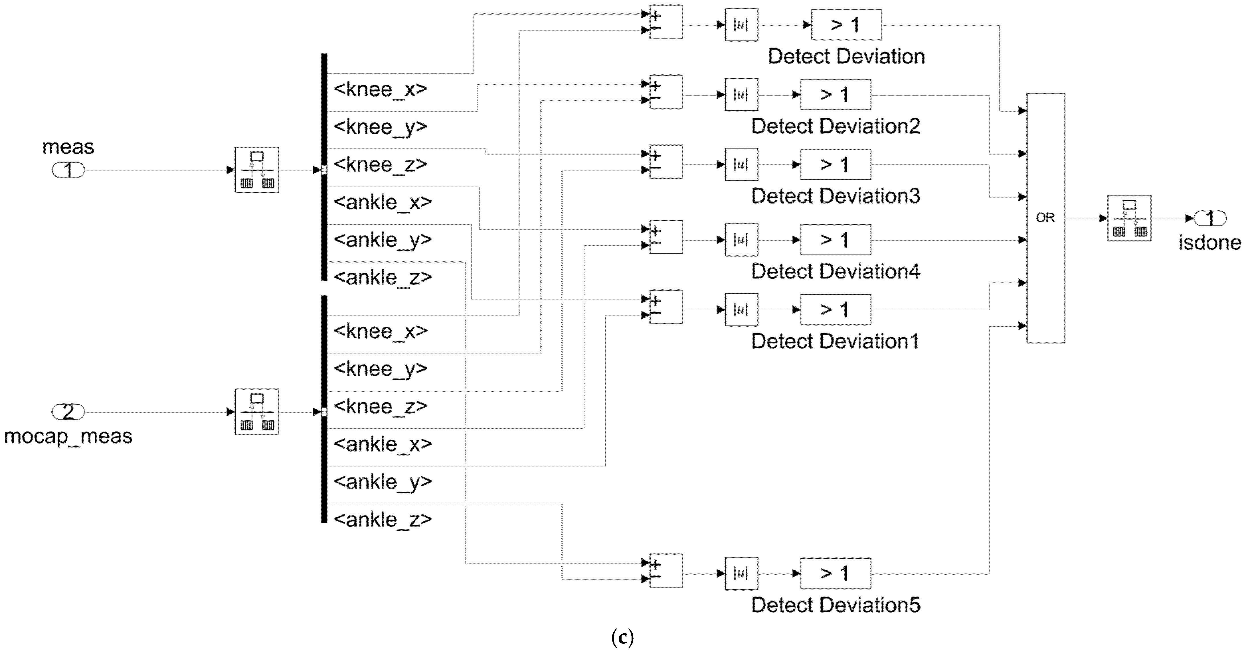
To prevent unstable behaviors during training, termination logic was implemented to end an episode when observed joint positions or joint angles exceed predefined thresholds (Figure 7, Termination Conditions) [36]. The termination subsystem outputs , and when , the episode ends and the environment resets, improving robustness and reducing divergence risk [24,40]. Using explicit constraint checks aligns with published safety considerations for rehabilitation robots and wearable exoskeleton systems, where bounded torque, speed, and joint range are treated as nonnegotiable guardrails [28,29,30,37].
3.4.4. RL Algorithm and Training Procedure
During training, the TD3 agent updates using reward and termination feedback, while during testing, remains fixed, as shown in Figure 7 [24,40]. As noted above, TD3 was adopted because the present task requires bounded continuous actions and benefits from the improved training stability provided by twin critics and delayed policy updates relative to baseline DDPG formulations [23,24]. Training proceeds episodically with repeated rollouts over the gait sequence [47]. At each step, the agent receives , outputs , advances the plant to produce , receives , evaluates , and stores transitions in an experience buffer for off-policy updates [24,40]. The critic learns two -functions to mitigate overestimation, and the actor is updated using the critic’s action-value estimates [24,48]. In the present manuscript, convergence is interpreted operationally as stabilization of episode-level reward trends together with bounded and repeatable policy behavior under the same testing conditions, rather than as proof of global optimality. This interpretation is consistent with the role of the RL module here as a proof-of-concept personalization layer within a system-level integration study.
For reproducibility, the TD3 environment and training settings are summarized as follows: observation dimension = 18, action dimension = 4, and the action range is bounded to . The environment sample time is s and each episode runs for s, resulting in 27 steps per episode, with a total of 200 training episodes. In this study, and were selected to provide a repeatable discretization of a fixed gait-cycle replay problem within the Simulink environment, rather than to define a deployment-ready continuous-time controller. The TD3 agent follows the standard MATLAB Reinforcement Learning Toolbox configuration, using a feedforward actor network that maps observations to bounded continuous actions (tanh output followed by action scaling) and two independent feedforward critic networks (twin critics) that estimate values from the concatenated state and action inputs. Unless otherwise stated, the TD3 agent was configured using the default settings provided by rlTD3AgentOptions, a MATLAB Reinforcement Learning Toolbox options object for specifying TD3 agent configuration and training parameters in this MATLAB version. Episode termination is triggered when joint-angle or task-space deviation checks violate predefined bounds; the termination subsystem uses a per-signal deviation threshold of 1, applied consistently during both training and evaluation.
3.4.5. Performance Evaluation and Validation Workflow
After training, performance was evaluated using in a simulation-based testing workflow (Figure 7, Testing panel) by comparing the time histories and path trajectories produced by the redesigned leg-assembly model against [24,36]. In addition, learned knee kinematics were compared against clinical gait analysis (CGA) references to provide an external plausibility check of gait-cycle trends [41,42]. Together, these comparisons support both time-domain tracking assessment and gait-cycle-normalized interpretation under the present model configuration, rather than full validation of adaptive clinical performance [41,42].
3.4.6. Derived Torque Estimation
To connect learned kinematic tracking to actuation-relevant quantities, segment angular accelerations were computed from the learned joint-angle trajectories using finite-difference differentiation [49]. Using the estimated angular accelerations and segment inertial properties, segment torques were estimated and analyzed versus gait-cycle percentage and joint angle [42]. These trends were then used to inform actuator sizing and assistance profiling. Within the layered torque architecture defined in Section 3.2, the RL controller contributes the baseline control action , either directly in torque form or through a lower-level controller, whereas the variable-gravity layer contributes the feedforward offset . The final commanded torque therefore combines the adaptive control contribution with the model-grounded gravity-compensation term. This decomposition preserves the physical interpretability of the gravity-support component while allowing the RL layer to adapt tracking behavior around that baseline.
3.5. Sit-to-Stand and Stand-to-Sit as an Integration Target
We treat STS and STSi as high-value integration targets because they require coordinated assistance across the hip, knee, and ankle, while also challenging balance, posture transition timing, and multi-joint synchronization; this emphasis is also consistent with recent review literature on soft exosuits for STS transfers and soft wearable rehabilitation devices [13,14], as well as established biomechanics studies of chair-rise mechanics [50,51]. In this manuscript, STS is positioned as an integration-level subsystem that links (i) variable-gravity assistance, (ii) learning-based control, and (iii) future patient-specific motion planning within the same safety-constrained architecture (Section 2) [28,29,30,37]. The present implementation pathway is grounded in prototype demonstrations and design documentation that establish mechanical feasibility and a scalable route toward later full-scale integration. At the current stage, implemented personalization features include user-adjustable gravity scaling, optional anthropometric parameter inputs during benchtop prototyping, individualized reference-trajectory tracking within the simulation framework, and adjustable-size leg-assembly concepts for future scale-up. Planned personalization features include systematic user-specific parameter configuration, full-scale adjustable structural integration, and closed-loop tuning of assistance magnitude and transition timing for different users.
3.5.1. Mechanical Integration Concept and Prototype Basis
A key mechanical requirement for realistic STS is enabling vertical translation of the leg assembly relative to the base system, because a fixed hip attachment can constrain the natural upward motion of the body’s center of mass during the rising phase [50,51]. In our design documentation, we addressed this by modifying the hip attachment plate so that the pins connecting the leg assembly to the base can slide vertically, enabling up to 24 inches of vertical travel during STS mode. This modification supports a more realistic transition trajectory while maintaining alignment with the support frame, and it preserves compatibility with the same attachment strategy used for variable-gravity training (Section 3.2) [28,29,30,34,35,37].
3.5.2. Motion Planning Target and Adjustable Assistance
For an initial, robust STS control objective suitable for prototyping, we adopt a simple posture goal in which hip, knee, and ankle angles are driven toward full extension and actuation stops once the target posture is reached. This yields a repeatable baseline for both STS and STSi and provides a clean template for graded assistance, where the device can complete the transition fully or partially depending on user needs and recovery stage [1,13,19,20,26]. This baseline objective also supports later replacement with trajectory-based targets derived from measured kinematics (Section 3.5.5) [41,42].
3.5.3. RL-Enabled Transition Assessment Using Patient-Specific Paths
To extend beyond a fixed target pose and toward patient-specific transitions, the RL framework can be adapted so that the reference trajectory represents STS or STSi joint paths, and the policy learns actions that reproduce those kinematics while maintaining constraint compliance [23,24,25,28,29,30,37,47,48]. In the present manuscript, this capability is discussed as a planned extension of the existing RL framework rather than as a fully implemented subsystem. This is consistent with the broader use of RL for lower-limb rehabilitation control, where policies are trained to reduce tracking error and adapt assistance under changing conditions [6,25]. Motion patterns can therefore remain clinically editable so that transition timing and assistance magnitude are tuned rather than hard-coded.
3.5.4. Patient Fit and Scalability for STS Deployment
Because STS performance is sensitive to anthropometrics and segment inertia, a practical STS integration concept also requires size adjustability [43,44,50]. The scalable concept uses modular structural rods and interchangeable braces so that leg length and fit can be adjusted across users without redesigning the entire system. This provides a physical basis for future scaling of STS and STSi motion plans and assistance levels across patient height and mass while remaining consistent with the variable-gravity torque-compensation formulation in Section 3.2 [43,44]. As an integration target, Figure 8 provides a baseline transition template that can be used in the near term for repeatable demonstrations, while future work will parameterize transition timing and assistance magnitude to accommodate patient height, mass, and partial-assist needs [50,51].
Figure 8.
Prototype motion sequences for posture transitions of the RoboREHAB leg assembly. (a) Sit-to-stand sequence. (b) Stand-to-sit sequence. Red arrows indicate the primary joint or segment motion emphasized at each step, including the direction of extension or flexion during the transition.
3.5.5. Data Pathway for Future Integration
Mocap data collected by the kinesiology department at The University of Texas at Tyler were recorded using markers placed at the neck, hip, knee, ankle, and toes. Hip, knee, and ankle trajectories were stored as candidate reference signals for future RL-based STS/STSi training and evaluation using the same and tracking-error structure defined in Section 3.4 [41,42,50,51]. In the current gait-training configuration used as the reference implementation, the network was trained for 200 episodes. Each episode replays the same gait sequence (one full gait cycle, time normalized to 0 to 100% of the gait cycle) for a fixed number of simulation steps. Mocap trajectories were preprocessed by (i) filtering to remove high-frequency noise, (ii) resampling to match the Simulink fixed step environment rate, and (iii) aligning coordinate frames between the mocap data and the leg assembly model. During training, the environment logs knee and ankle task space positions and joint angles at every simulation step. The reward function is the negative sum of absolute tracking errors in knee and ankle task space positions (), consistent with Section 3.4.2, and the termination logic triggers when joint angles or task space positions exceed predefined bounds (Section 3.4.3).
3.6. Verification and Prototype Demonstrations
Verification was structured to cross-check the redesigned leg assembly across three representations: (i) the Simulink plant used for learning-based controller evaluation, (ii) CAD-based kinematic replay, and (iii) benchtop-feasible prototype configurations. First, we compared joint time histories and planar joint-path trajectories from the redesigned simulation model against mocap references to assess tracking consistency and to localize gait-cycle regions associated with persistent deviations [10,41]. Where applicable, agreement was interpreted using gait-cycle-normalized comparisons and maximum-deviation checks so that mismatch regions could be traced back to specific linkage-geometry sensitivities and segment-parameter assumptions [10,41,42].
Second, we used a CAD-to-multibody consistency workflow to reduce model-form mismatch between the SolidWorks mechanism and the multibody plant used in controller testing. The assembly was exported via Simscape Multibody Link and imported into Simscape Multibody to verify joint definitions, allowable degrees of freedom, and range-of-motion constraints, and to replay candidate joint trajectories under a physics-based multibody representation [38,39]. This step functions as an independent toolchain-level check that CAD geometry, joint constraints, and simulation evaluation assumptions remain aligned prior to hardware-scale prototyping [38,39].
Prototype feasibility was evaluated using two complementary tracks. Track A targeted functional packaging and integration realism by assembling a benchtop prototype with embedded actuation and wiring, then generating comparable joint-path trajectories via a SolidWorks motion study. Because the benchtop attachment used a fixed hip reference, we constructed a fixed-hip mocap baseline by removing hip translation components from downstream joint trajectories, enabling a controlled comparison that preserves knee and ankle path-shape features while maintaining repeatability under a constrained interface [10,41].
Track B targeted rapid iteration under manufacturing and actuator limits by adopting a scaled prototype strategy. This scaled prototype was used specifically for rapid benchtop iteration before full-scale fabrication and is distinct from the full-scale adjustable-size leg assembly described in Section 3.3.4. Segment dimensions were selected to satisfy 3D-printing envelope constraints and candidate motor torque-speed capabilities, enabling repeated build-test cycles before committing to full-scale fabrication. This scaled CAD model included motor-compatible joint features and a dedicated base intended for repeatable bench testing, consistent with common rapid-prototyping practice for early-stage mechanism validation and design iteration [45,46].
4. Results
This section reports results in two evidence categories and distinguishes them explicitly throughout. Simulation-based results support the mechanical redesign, preliminary RL-based trajectory tracking behavior, derived torque trends, and CAD-based replay verification under the present model configuration [23,24,36,38,39,40]. All percentage improvements reported in this manuscript (e.g., 66%, 55%, 72%, 66%) are drawn exclusively from the simulation evaluation set and are computed as relative reductions versus the corresponding fixed-gravity, predefined-trajectory baseline under the same simulated scenario definitions and metric formulations. Benchtop and prototype results support embedded feasibility for variable-gravity torque modulation and illustrate integration constraints related to actuator capability, joint range, and scaling [28,29,30,31,34,37]. Future work, discussed separately, concerns hardware-in-the-loop testing, instrumented full-scale integration, and eventual human-subject evaluation. Accordingly, the present Section 4 should be interpreted as reporting system-level simulation evidence and benchtop subsystem feasibility, rather than robust controller validation or clinical performance.
4.1. RL-Based Trajectory Tracking Performance
4.1.1. Time-History Tracking (Joint Positions)
The Simulink RL environment was trained to reproduce mocap kinematics using the redesigned leg assembly model [23,24,36,40]. In the present simulation setup, the hip joint histories match the mocap reference closely because the hip coordinates were directly driven by mocap data. For the knee joint, the redesigned assembly reproduced the mocap trends with a reported maximum deviation of 43.1 mm in knee x-position during heel strike and 15.9 mm in knee y-position during the same gait region while remaining within an overall 5% margin of error relative to the mocap reference.
For the ankle joint, the x-position history showed larger deviations, including a reported maximum deviation of 78.2 mm in the loading phase, while the y-position history deviated less and exceeded the 5% margin primarily during heel strike (maximum deviation 21.9 mm) due to compounded upstream errors from knee and ankle tracking during that phase. Collectively, these simulation results suggest that the redesigned kinematic structure combined with the present RL configuration can reproduce key temporal and spatial gait patterns under the evaluated conditions, with larger errors concentrated in gait phases that are more sensitive to segment-length assumptions and subject-specific anthropometrics [41,42,43,44].
4.1.2. Path-Trajectory Comparisons (Redesigned vs. Original)
Beyond time-history tracking, kinematic alignment was evaluated by comparing joint path trajectories across the gait cycle for the original leg assembly, the redesigned assembly, and mocap references [41,42]. The redesigned configuration produces joint paths that more closely follow the reference trajectories, with the most visible improvements at the knee and ankle. These gains are consistent with added kinematic capability at the knee mechanism that reduces path mismatch during critical gait phases and yields smoother joint-path evolution over the cycle [41,42].
4.1.3. External Plausibility Check Using Clinical Gait Analysis (CGA)
The RL-generated knee angle profile was compared against clinical gait analysis reference trends as an external plausibility check, suggesting that the learned gait profile is not only close to the training mocap but also consistent with expected knee-angle progression over the gait cycle [41,42].
4.2. Balance and Sit-to-Stand Related Evidence
4.2.1. Balance Recovery Behavior Under Perturbation-like Conditions
To evaluate whether the redesigned leg assembly and RL-based controller extend beyond nominal gait replay, balance-recovery-oriented simulations were conducted under perturbation-like conditions. These results suggest that the integrated kinematic redesign and learning-based control structure can support stabilization tasks while preserving interpretable torque behavior within an explicit safety envelope [28,29,30,37].
4.2.2. Joint-Path Consistency During Balance-Oriented Trials
During balance recovery, joint trajectories exhibit stronger interdependence than during steady gait tracking. The knee trajectory remained comparatively stable, while the hip joint demonstrated larger corrective motion, reflecting a hip-dominant stabilization role under perturbation-like disturbances [52,53]. The ankle joint contributed secondary stabilization effects while maintaining bounded motion profiles, consistent with multi-joint coordination patterns commonly described in balance control [52,53]. Collectively, the results indicate coordinated multi-joint behavior rather than isolated tracking at individual joints.
4.2.3. Sit-to-Stand as a Functional Integration Target
STS represents a functional transition requiring synchronized torque generation across the hip, knee, and ankle, along with controlled center-of-mass displacement [50,51]. Within the RoboREHAB architecture, the same state definitions, torque constraints, and gravity-compensation framework used for gait tracking are directly applicable to STS motion [28,29,30,34,35,37,50,51]. Simulation trials indicate that the present system structure can accommodate multi-joint extension patterns characteristic of STS without instability or torque saturation. Rather than presenting STS as a validated clinical outcome, the present results establish architectural compatibility and control feasibility for future experimental validation and human-subject testing [28,29,30,37].
4.3. Variable-Gravity Prototype Evidence
4.3.1. Embedded Control Stack Feasibility
The variable-gravity torque compensation layer is implemented as a physically grounded feedforward structure that computes gravity-induced torques and scales them using a gravity factor [34,35]. From an embedded perspective, the system requires real-time joint-angle estimation, deterministic torque computation, and user-adjustable assistance levels [31,32,33]. An Arduino-based control stack was configured to acquire joint-angle information through inertial sensing, process gravity-scaling commands, and transmit motor commands via dedicated drivers. The computational burden of gravity scaling remains lightweight, supporting real-time implementation without high-performance hardware requirements [31,32,33].
4.3.2. Real-Time User Adjustment and Output Observability
Adjustable training intensity is achieved through continuous tuning of the gravity factor. A potentiometer-based user interface enables real-time modification of assistance level, while LED indicators and serial monitoring provide observable feedback of parameter changes and command outputs. Changes in the gravity factor produce immediate and proportional changes in the feedforward torque offsets, consistent with the deterministic scaling structure in the compensation formulation [34,35]. This observability supports safety review and debugging during benchtop validation [28,29,30,37].
4.3.3. Benchtop Prototyping and Scale-Up Pathway
Prototype development followed a staged approach beginning with small-scale benchtop assemblies to validate mechanical integration, sensor wiring, and actuator response, reducing integration risk before progressing to larger-scale or wearable implementations [45,46]. The knee mechanism and multi-link structure were validated at the component level before full assembly integration. This modular validation strategy supports iterative refinement and facilitates transition toward adjustable-length configurations for user-specific adaptation [43,44,45,46]. Together, these results indicate that the variable-gravity concept is not limited to simulation and can be pursued through a reproducible embedded and mechanical implementation pathway suitable for further experimental expansion.
5. Discussion
The primary contribution of this manuscript is an integrated, evidence-mapped description of RoboREHAB. Rather than presenting variable-gravity, mechanical redesign, and RL control as separate efforts, we connect them through a single system architecture with explicit interfaces, shared signal definitions, and a staged validation pathway. This integration matters because lower-limb rehabilitation systems are often evaluated in fragmented ways that make it difficult to determine what has been verified in simulation, what has been demonstrated in benchtop prototypes, and what remains to be established before a full platform demonstration [6,10,17,18]. By aligning terminology, state definitions, and evaluation metrics across modules, the present manuscript provides a traceable system narrative intended to reduce ambiguity for readers who want to reproduce, extend, or translate the platform [6,36,38,39,40]. Compared with rehabilitation studies that focus primarily on either device mechanics, assistance concepts, or adaptive control in isolation, the present work emphasizes traceable integration across these layers within a single evidence-mapped architecture [10,16,17,18,25,28].
A central architectural choice is the separation of a physically interpretable torque-compensation layer from the adaptive RL layer. The torque-compensation layer provides a transparent, model-based mechanism to modulate effective gravitational loading, supporting safety review and interpretable parameter tuning [28,29,30,34,35,37]. In contrast, the RL policy operates as a personalization mechanism that learns residual actions or trajectory corrections around a reference motion, consistent with actor–critic formulations used in continuous-control learning [23,24,25,47,48]. This decomposition provides two practical benefits. First, it preserves a predictable baseline structure for gravity-related torques, reducing reliance on a learned black-box component for safety-critical loading behavior [28,29,30,37]. Second, it enables modular development, where the assistance level (gravity factor) can be tuned independently of learning-policy design [34,35]. In rehabilitation contexts where bounded and repeatable motion is prioritized, this separation supports a control philosophy in which learning augments, rather than replaces, physically grounded modeling and constraint enforcement [6,28,29,30,37].
The evidence reported in this manuscript should be interpreted according to its validation level. Simulation results support the mechanical redesign, the preliminary RL control pathway, and the system-level interpretation of derived torque behavior under the present model configuration, whereas benchtop results support embedded feasibility and reveal practical implementation constraints. Future work concerns hardware-in-the-loop integration, instrumented full-scale testing, and eventual IRB-approved human-subject evaluation. Accordingly, the present manuscript should be read as a system-level integration and feasibility study rather than as a robust validation of an adaptive rehabilitation controller or a completed clinical validation paper. This distinction is necessary to avoid overinterpretation while still recognizing that the staged evidence reported here is sufficient to justify the next phases of instrumentation, HIL testing, and eventual IRB-approved human-subject evaluation.
Several limitations define the current maturity level. Most importantly, the system has not yet undergone human-subject validation, and therefore no clinical claims are made, consistent with the distinction between engineering feasibility evidence and clinical outcomes in rehabilitation robotics practice [6,11]. Hardware evidence is currently limited to benchtop feasibility demonstrations rather than full-scale characterization of actuator bandwidth, torque accuracy, thermal limits, and repeatability under load. The RL results are presently limited to simulation-based evaluation under a coarse fixed replay configuration and therefore should be interpreted as preliminary controller evidence rather than robust validation of adaptive rehabilitation performance. The STS subsystem is treated as an integration target and is not yet fully incorporated into the end-to-end control and safety architecture with quantitative validation, even though the biomechanics and constraints of chair rise have been well characterized in prior studies [50,51]. In addition, the modular walkway concepts are currently CAD-level designs and require fabrication and controlled perturbation testing with instrumentation before they can support systematic perturbation-training studies, consistent with published safety and evaluation expectations for rehabilitation robots and wearable exoskeletons [28,29,30,37]. Finally, the current results rely on reference trajectories derived from mocap and clinical gait analysis, so generalization of the learned policy to unmodeled subjects, altered anthropometrics, and different walking conditions remains an open question for future work [41,42,43,44].
These limitations motivate a stepwise integration plan focused on measurable safety and performance milestones. First, hardware-in-the-loop testing should couple the embedded variable-gravity implementation to the simulation-based RL policy, allowing verification of timing, saturation behavior, and fault handling under realistic computational and communication constraints [28,29,30,36,37,38,39,40]. Second, full-scale prototype testing should incorporate instrumentation sufficient to quantify joint angles, actuator currents, and applied torques, enabling validation of torque scaling with the gravity factor and the consistency of assistance delivery across gait phases [31,32,33,34,35]. Third, task progression should proceed from steady gait to transitional tasks such as STS and STSi, followed by controlled perturbation modules on the walkway platform, with explicit acceptance criteria including bounded joint motion and torque and speed limit compliance [28,29,30,37,50,51]. This staged approach is intended to form a credible validation ladder before any IRB-approved clinical feasibility study [1,4].
More broadly, the modular structure of RoboREHAB is designed to facilitate incremental extension. The architecture can incorporate additional sensing modalities (for example, inertial sensing enhancements or complementary load measurement) and improved biomechanical parameter identification, including patient-specific tuning of segment parameters [31,32,33,43,44]. Similarly, the learning-based layer can be extended toward robustness-oriented training strategies (for example, subject-parameter variation and constraint-aware learning) while preserving safety constraints [24,25,28,29,30,37,47,48]. These directions are not required to support the present claims but represent a practical roadmap for strengthening system-level evidence and translational readiness [6,28,29,30,37].
6. Conclusions
This paper presents an integrated description of the RoboREHAB platform, including unified architecture, explicit module interfaces, and an evidence-mapped pathway that links variable-gravity assistance, simulation-based learning control, benchtop prototype feasibility, and future validation steps within a single system narrative. The platform integrates (i) a redesigned leg assembly intended to better match knee kinematics, (ii) a Simulink-based RL controller prototype trained using mocap-derived reference trajectories, and (iii) a variable-gravity assistance module implemented through joint-level torque compensation with an embedded Arduino-based actuation concept.
The reported simulation evidence supports the feasibility of co-developing mechanical design and a preliminary learning-based control pathway within the present system architecture. Quantitative results derived from the simulation evaluation set indicate reduced gait trajectory error (66%), improved balance recovery time (55%), reduced stride deviation (72%), and decreased joint torque variability (66%), together with trajectory tracking within an approximately 5% error margin relative to mocap references under the evaluated simulation conditions. Importantly, the manuscript distinguishes simulation-based evaluation from benchtop prototype feasibility and future validation stages and ties each reported outcome to a module-level evidence category to maintain traceability and limit claims to what has been demonstrated.
Prototype-oriented evidence further supports the subsystem-level feasibility of variable-gravity operation through sensor-driven parameter updates and user-adjustable gravity scaling. The embedded pathway indicates that real-time assistance modulation can be implemented with readily available components, and that a consistent gravity-factor definition can be maintained across simulation and hardware demonstrations. In addition, the mechanical prototypes and design documentation outline a scale-up route toward full-size integration, including provisions for user-size adjustability and planned extension to transitional tasks such as STS and STSi.
Future work should prioritize system-level integration and staged validation with measurable safety and performance milestones. Key steps include (i) hardware-in-the-loop evaluation that couples the embedded variable-gravity implementation with the simulation-trained RL policy under realistic timing, saturation, and fault conditions; (ii) full-scale benchtop testing with instrumentation to quantify joint angles, actuator currents, and applied torques to verify assistance scaling and robustness under load; and (iii) progressive task expansion from steady gait to functional transitions and controlled perturbation scenarios. These future stages are necessary before any claim of robust adaptive controller validation or clinical feasibility can be made.
Author Contributions
Conceptualization, C.-H.G.; methodology, C.-H.G. and J.A.; software, J.A. and C.B.; validation, C.-H.G., J.A. and C.B.; formal analysis, C.-H.G. and J.A.; investigation, J.A. and C.B.; resources, C.-H.G.; data curation, J.A. and C.B.; writing—original draft preparation, C.-H.G.; writing—review and editing, C.-H.G., J.A. and C.B.; visualization, J.A. and C.B.; supervision, C.-H.G.; project administration, C.-H.G.; funding acquisition, C.-H.G. All authors have read and agreed to the published version of the manuscript.
Funding
This research received no external funding.
Institutional Review Board Statement
Not applicable.
Informed Consent Statement
Not applicable.
Data Availability Statement
The data supporting the reported results include simulation outputs generated within the Simulink environment and motion capture (mocap) reference trajectories used for training and evaluation. The mocap datasets contain subject-specific kinematic information and are not publicly available due to privacy and ethical considerations. The following materials are available from the corresponding author upon reasonable request and subject to institutional approval: (i) the Simulink environment model, including the observation, reward, and termination subsystems; (ii) parameter tables for the leg model and gravity compensation; and (iii) processed, anonymized reference trajectories or derived feature representations sufficient to reproduce the reported tracking metrics.
Acknowledgments
The authors gratefully acknowledge X. Neil Dong and W. Jeon for providing access to the motion-capture datasets used in this study. Their support in data collection and sharing was essential for the development and validation of the simulation framework. During the preparation of this manuscript, the authors used ChatGPT (version 5.2, OpenAI) for the purposes of grammar checking and text editing. The authors have reviewed and edited the output and take full responsibility for the content of this publication.
Conflicts of Interest
The authors declare no conflicts of interest.
Abbreviations
The following abbreviations are used in this manuscript:
| RL | Reinforcement Learning |
| RL-IK | Reinforcement Learning-Inverse Kinematics |
| RoboREHAB | Robot-assisted rehabilitation platform |
| RAGT | Robot-Assisted Gait Training |
| STS | Sit-to-Stand |
| STSi | Stand-to-Sit |
| SCI | Spinal Cord Injury |
| TBI | Traumatic Brain Injury |
| DDPG | Deep Deterministic Policy Gradient |
| TD3 | Twin Delayed Deep Deterministic Policy Gradient |
| MPC | Model Predictive Control |
| Mocap | Motion Capture |
| IMU | Inertial Measurement Unit |
| COM | Center of Mass |
| CGA | Clinical Gait Analysis |
| CAD | Computer-Aided Design |
| IRB | Institutional Review Board |
Appendix A
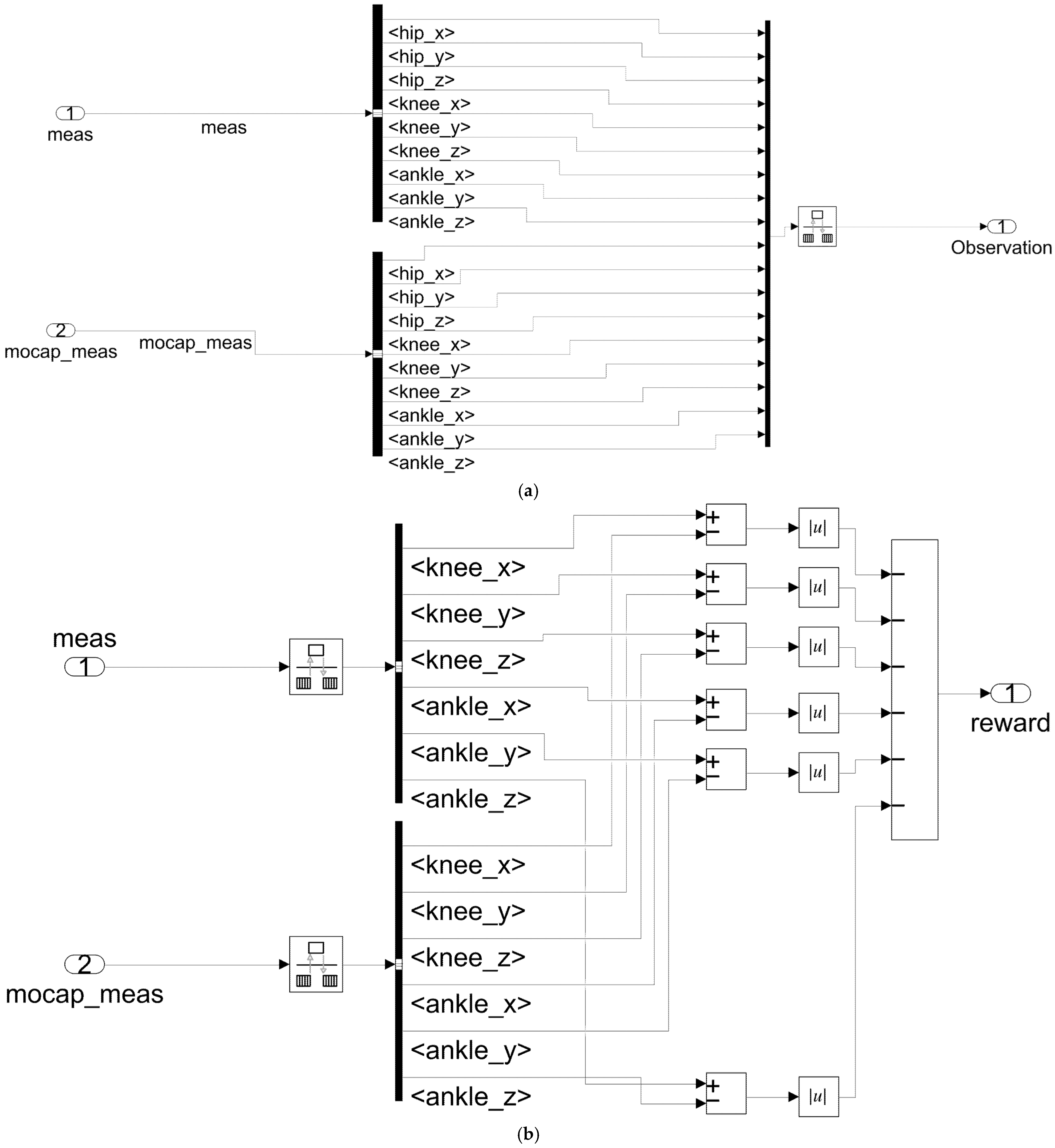
The block diagrams of the observation, reward, and termination subsystems are illustrated in Figure A1 below.
Figure A1.
Observation, reward, and termination subsystems used in the Simulink RL environment. (a) Observation subsystem. (b) Reward subsystem. (c) Termination subsystem. These blocks generate the observation vector, scalar reward, and episode termination flag used during RL training.
References
- Winstein, C.J.; Stein, J.; Arena, R.; Bates, B.; Cherney, L.R.; Cramer, S.C.; Deruyter, F.; Eng, J.J.; Fisher, B.; Harvey, R.L.; et al. Guidelines for adult stroke rehabilitation and recovery: A guideline for healthcare professionals from the American Heart Association/American Stroke Association. Stroke 2016, 47, e98–e169. [Google Scholar] [CrossRef] [Scilit]
- Anderson, K.; Aito, S.; Atkins, M.; Biering-Sørensen, F.; Charlifue, S.; Curt, A.; Ditunno, J.; Glass, C.; Marino, R.; Marshall, R.; et al. Functional recovery measures for spinal cord injury: An evidence-based review for clinical practice and research. J. Spinal Cord Med. 2008, 31, 133–144. [Google Scholar] [CrossRef] [Scilit]
- Dang, B.; Chen, W.; He, W.; Chen, G. Rehabilitation treatment and progress of traumatic brain injury dysfunction. Neural Plast. 2017, 2017, 1582182. [Google Scholar] [CrossRef] [Scilit] [PubMed]
- Department of Veterans Affairs; Department of Defense. VA/DoD Clinical Practice Guideline for the Management of Stroke Rehabilitation. 2024. Available online: https://www.healthquality.va.gov/guidelines/Rehab/stroke/ (accessed on 21 January 2026).
- Marín-Medina, D.S.; Arenas-Vargas, P.A.; Arias-Botero, J.C.; Gómez-Vásquez, M.; Jaramillo-López, M.F.; Gaspar-Toro, J.M. New approaches to recovery after stroke. Neurol. Sci. 2024, 45, 55–63. [Google Scholar] [CrossRef] [Scilit]
- Rad, O.L.; Brisan, C. Control algorithms in robot-assisted rehabilitation: A systematic review. Appl. Sci. 2025, 15, 9184. [Google Scholar] [CrossRef] [Scilit]
- Park, Y.H.; Lee, D.H.; Lee, J.H. A comprehensive review: Robot-assisted treatments for gait rehabilitation in stroke patients. Medicina 2024, 60, 620. [Google Scholar] [CrossRef] [Scilit]
- Lee, J.H.; Kim, G. Effectiveness of robot-assisted gait training in stroke rehabilitation: A systematic review and meta-analysis. J. Clin. Med. 2025, 14, 4809. [Google Scholar] [CrossRef] [Scilit]
- Dollar, A.M.; Herr, H.M. Lower extremity exoskeletons and active orthoses: Challenges and state-of-the-art. IEEE Trans. Robot. 2008, 24, 144–158. [Google Scholar] [CrossRef] [Scilit]
- Rodríguez-Fernández, A.; Lobo-Prat, J.; Font-Llagunes, J.M. Systematic review on wearable lower-limb exoskeletons for gait training in neuromuscular impairments. J. Neuroeng. Rehabil. 2021, 18, 22. [Google Scholar] [CrossRef] [Scilit]
- Esquenazi, A.; Packel, A. Robotic-assisted gait training and restoration. Am. J. Phys. Med. Rehabil. 2012, 91, S217–S227. [Google Scholar] [CrossRef] [Scilit] [PubMed]
- Hasan, S.; Alam, N. Comprehensive comparative analysis of lower limb exoskeleton research: Control, design, and application. Actuators 2025, 14, 342. [Google Scholar] [CrossRef] [Scilit]
- Perera, C.K.; Gopalai, A.A.; Gouwanda, D.; Nurzaman, S.G. A focused review on soft robotic exosuits for sitting to standing transfers. Robot. Rep. 2024, 2, 65–84. [Google Scholar] [CrossRef] [Scilit]
- Guo, W.; Katiyar, S.A.; Davis, S.; Nefti-Meziani, S. Overview: A comprehensive review of soft wearable rehabilitation and assistive devices, with a focus on the function, design and control of lower-limb exoskeletons. Machines 2025, 13, 1020. [Google Scholar] [CrossRef] [Scilit]
- Jiang, C.; Xiao, J.; Wei, H.; Wang, M.Y.; Chen, C. Review on portable-powered lower limb exoskeletons. Sensors 2024, 24, 8090. [Google Scholar] [CrossRef] [Scilit]
- Masengo, G.; Zhang, X.; Dong, R.; Alhassan, A.B.; Hamza, K.; Mudaheranwa, E. Lower limb exoskeleton robot and its cooperative control: A review, trends, and challenges for future research. Front. Neurorobot. 2023, 16, 913748. [Google Scholar] [CrossRef] [Scilit] [PubMed]
- Coser, O.; Tamantini, C.; Soda, P.; Zollo, L. AI-based methodologies for exoskeleton-assisted rehabilitation of the lower limb: A review. Front. Robot. AI 2024, 11, 1341580. [Google Scholar] [CrossRef] [Scilit]
- Hobbs, B.; Artemiadis, P. A review of robot-assisted lower-limb stroke therapy: Unexplored paths and future directions in gait rehabilitation. Front. Neurorobot. 2020, 14, 19. [Google Scholar] [CrossRef] [Scilit]
- Mehrholz, J.; Thomas, S.; Elsner, B. Treadmill training and body weight support for walking after stroke. Cochrane Database Syst. Rev. 2017, 8, CD002840. [Google Scholar] [CrossRef] [Scilit]
- Jiang, Z.; Zhang, X.; Fu, Q.; Tao, Y. Effects of body weight support training on balance and walking function in stroke patients: A systematic review and meta-analysis. Front. Neurol. 2024, 15, 1413577. [Google Scholar] [CrossRef] [Scilit]
- Veldema, J.; Jansen, P. Aquatic therapy in stroke rehabilitation: Systematic review and meta-analysis. Acta Neurol. Scand. 2021, 143, 221–241. [Google Scholar] [CrossRef] [Scilit]
- Hornby, T.G.; Plawecki, A.; Lotter, J.K.; Scofield, M.E.; Lucas, E.; Henderson, C.E. Gains in daily stepping activity in people with chronic stroke after high-intensity gait training in variable contexts. Phys. Ther. 2022, 102, pzac073. [Google Scholar] [CrossRef] [Scilit] [PubMed]
- Lillicrap, T.P.; Hunt, J.J.; Pritzel, A.; Heess, N.; Erez, T.; Tassa, Y.; Silver, D.; Wierstra, D. Continuous control with deep reinforcement learning. arXiv 2015, arXiv:1509.02971. [Google Scholar]
- Fujimoto, S.; Hoof, H.V.; Meger, D. Addressing function approximation error in actor-critic methods. In Proceedings of the 35th International Conference on Machine Learning (PMLR), Stockholm, Sweden, 10–15 July 2018; Volume 80, pp. 1587–1596. [Google Scholar]
- Luo, S.; Androwis, G.; Adamovich, S.; Su, H.; Nunez, E.; Zhou, X. Reinforcement learning and control of a lower extremity exoskeleton for squat assistance. Front. Robot. AI 2021, 8, 702845. [Google Scholar] [CrossRef] [Scilit]
- Menga, G.; Ghirardi, M. Control of the sit-to-stand transfer of a biped robotic device for postural rehabilitation. Robotics 2019, 8, 91. [Google Scholar] [CrossRef] [Scilit]
- Mashud, G.; Hasan, S.K.; Alam, N. Advances in control techniques for rehabilitation exoskeleton robots: A systematic review. Actuators 2025, 14, 108. [Google Scholar] [CrossRef] [Scilit]
- Foroutannia, A.; Mohammadian, M. A comprehensive survey of lower limb assistive exoskeleton robots: Models, dynamics, mechanics, and control. Robot. Auton. Syst. 2026, 195, 105232. [Google Scholar] [CrossRef] [Scilit]
- Nasr, A.; Inkol, K.; McPhee, J. Safety in wearable robotic exoskeletons: Design, control, and testing guidelines. J. Mech. Robot. 2025, 17, 050801. [Google Scholar] [CrossRef] [Scilit]
- Bessler, J.; Prange-Lasonder, G.B.; Schaake, L.; Saenz, J.F.; Bidard, C.; Fassi, I.; Valori, M.; Lassen, A.B.; Buurke, J.H. Safety assessment of rehabilitation robots: A review identifying safety skills and current knowledge gaps. Front. Robot. AI 2021, 8, 602878. [Google Scholar] [CrossRef] [Scilit] [PubMed]
- Figueiredo, J.; Carvalho, S.P.; Vilas-Boas, J.P.; Gonçalves, L.M.; Moreno, J.C.; Santos, C.P. Wearable inertial sensor system towards daily human kinematic gait analysis: Benchmarking analysis to MVN BIOMECH. Sensors 2020, 20, 2185. [Google Scholar] [CrossRef] [Scilit]
- Zhang, L.; Tian, X.; Fan, Y.; Jiang, T.; Gu, S.; Xu, L. Development and efficacy assessment of an angle sensor-integrated upper limb exoskeleton system for autonomous rehabilitation training. Sensors 2025, 25, 3984. [Google Scholar] [CrossRef] [Scilit] [PubMed]
- Wang, F.; Liang, W.; Afzal, H.M.R.; Fan, A.; Li, W.; Dai, X.; Liu, S.; Hu, Y.; Li, Z.; Yang, P. Estimation of lower limb joint angles and joint moments during different locomotive activities using the inertial measurement units and a hybrid deep learning model. Sensors 2023, 23, 9039. [Google Scholar] [CrossRef] [Scilit] [PubMed]
- Verdel, D.; Bastide, S.; Vignais, N.; Bruneau, O.; Berret, B. Human weight compensation with a backdrivable upper-limb exoskeleton: Identification and control. Front. Bioeng. Biotechnol. 2022, 9, 796864. [Google Scholar] [CrossRef] [Scilit]
- Kwak, J.; Choi, W.; Lee, C.; Oh, S. Gravity and impedance compensation of body weight support system driven by two series elastic actuators. IEEE/ASME Trans. Mechatron. 2022, 27, 190–201. [Google Scholar] [CrossRef] [Scilit]
- MathWorks. Train Biped Robot to Walk Using Reinforcement Learning Agents (DDPG, TD3) Example Workflow. Available online: https://www.mathworks.com/help/reinforcement-learning/ug/train-biped-robot-to-walk-using-reinforcement-learning-agents.html (accessed on 21 January 2026).
- Zhu, Z.; Liu, L.; Zhang, W.; Jiang, C.; Wang, X.; Li, J. Design and motion control of exoskeleton robot for paralyzed lower limb rehabilitation. Front. Neurosci. 2024, 18, 1355052. [Google Scholar] [CrossRef] [Scilit]
- MathWorks. Get Started with Simscape Multibody Link (Export CAD Assemblies for Use in Simscape Multibody Software). Available online: https://www.mathworks.com/help/smlink/getting-started-with-simmechanics-link.html (accessed on 21 January 2026).
- MathWorks. Model Import (Import a Multibody Model into the Simscape Multibody Environment). Available online: https://www.mathworks.com/help/sm/cad-import.html (accessed on 21 January 2026).
- MathWorks. Twin-Delayed Deep Deterministic (TD3) Policy Gradient Agents (Algorithm Documentation). Available online: https://www.mathworks.com/help/reinforcement-learning/ug/td3-agents.html (accessed on 21 January 2026).
- Whittle, M.W. Gait Analysis: An Introduction, 3rd ed.; Butterworth-Heinemann: Oxford, UK; Elsevier: Boston, MA, USA, 2002. [Google Scholar]
- Winter, D.A. The Biomechanics and Motor Control of Human Gait: Normal, Elderly and Pathological, 2nd ed.; Waterloo Biomechanics: Waterloo, ON, Canada, 1991. [Google Scholar]
- Dempster, W.T. The anthropometry of body action. Ann. N. Y. Acad. Sci. 1955, 63, 559–585. [Google Scholar] [CrossRef] [Scilit]
- Otmani, S.; Michon, G.; Watier, B. Use of adult anthropometric tables to estimate children body segment inertial parameters. Int. Biomech. 2023, 10, 18–28. [Google Scholar] [CrossRef] [Scilit]
- Gibson, I.; Rosen, D.W.; Stucker, B.; Khorasani, M. Additive Manufacturing Technologies, 3rd ed.; Springer Nature AG: Cham, Switzerland, 2021. [Google Scholar]
- Ulrich, K.T.; Eppinger, S.D.; Yang, M.C. Product Design and Development, 7th ed.; McGraw-Hill Education: New York, NY, USA, 2020. [Google Scholar]
- Sutton, R.S.; Barto, A.G. Reinforcement Learning: An Introduction, 2nd ed.; MIT Press: Cambridge, MA, USA, 2018. [Google Scholar]
- Konda, V.R.; Tsitsiklis, J.N. Actor-Critic Algorithms. In Advances in Neural Information Processing Systems 12 (NIPS 1999); Solla, S.A., Leen, T.K., Müller, K.-R., Eds.; The MIT Press: Cambridge, MA, USA, 2000; pp. 1008–1014. [Google Scholar]
- Chapra, S.C.; Canale, R.P. Numerical Methods for Engineers, 6th ed.; McGraw-Hill Education: New York, NY, USA, 2010; pp. 653–668. [Google Scholar]
- Schenkman, M.; Berger, R.A.; Riley, P.O.; Mann, R.W.; Hodge, W.A. Whole-body movements during rising to standing from sitting. Phys. Ther. 1990, 70, 638–648. [Google Scholar] [CrossRef] [Scilit] [PubMed]
- Riley, P.O.; Schenkman, M.L.; Mann, R.W.; Hodge, W.A. Mechanics of a constrained chair-rise. J. Biomech. 1991, 24, 77–85. [Google Scholar] [CrossRef] [Scilit] [PubMed]
- Horak, F.B.; Nashner, L.M. Central programming of postural movements: Adaptation to altered support-surface configurations. J. Neurophysiol. 1986, 55, 1369–1381. [Google Scholar] [CrossRef] [Scilit]
- Nashner, L.M. Organization and programming of motor activity during posture control. Prog. Brain Res. 1979, 50, 177–184. [Google Scholar] [CrossRef] [Scilit]
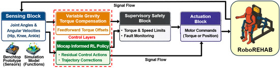
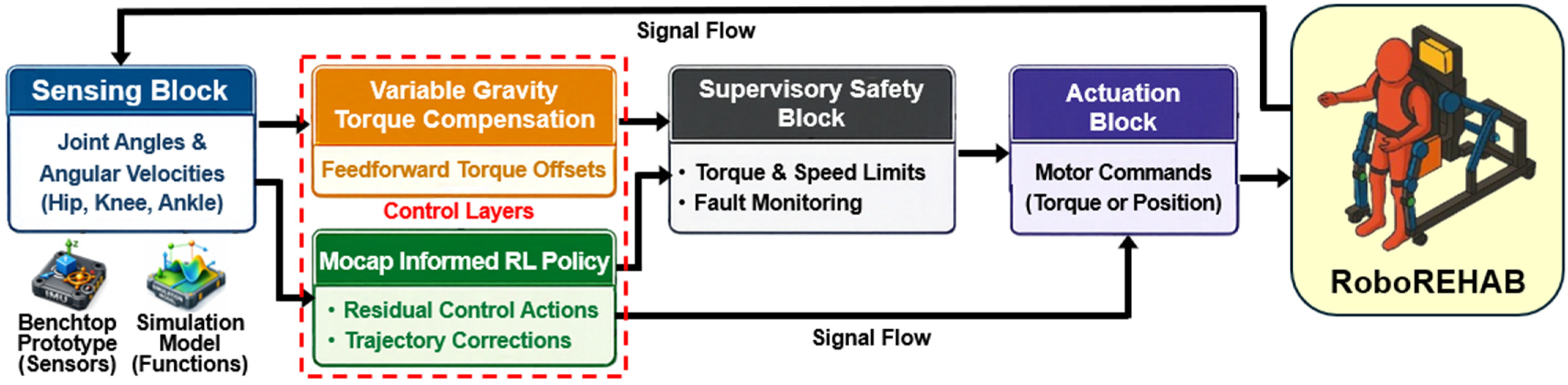
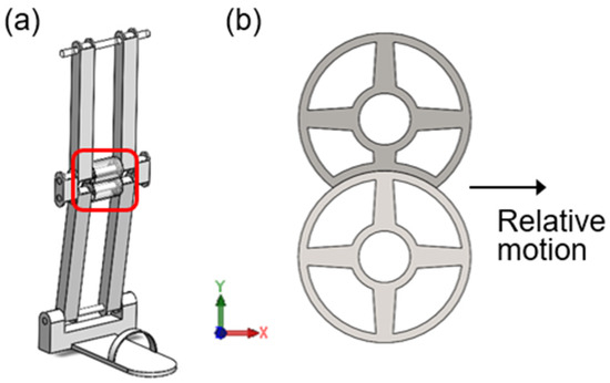
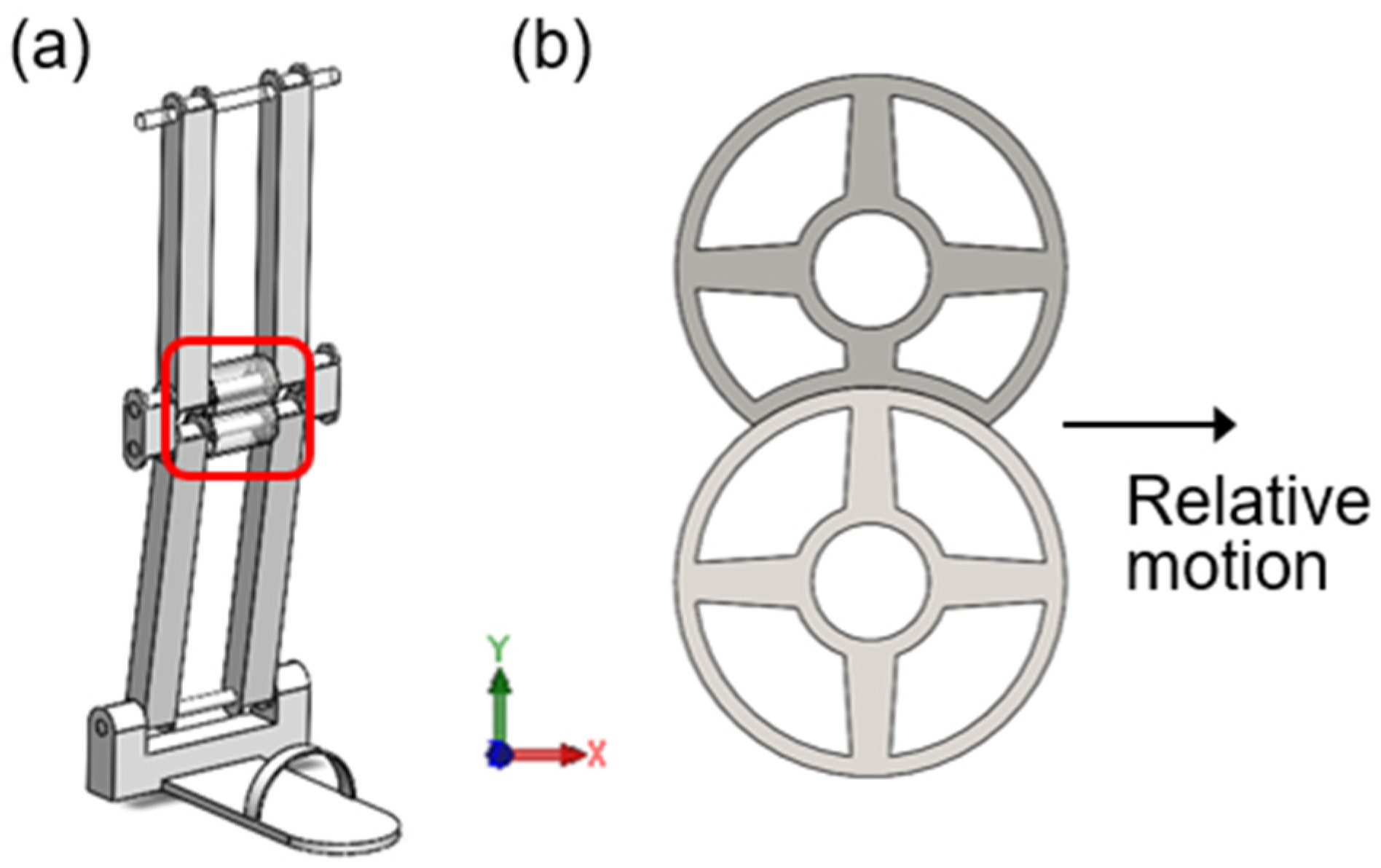
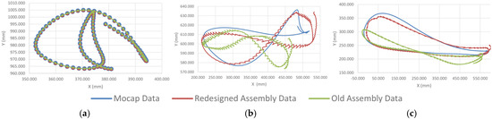
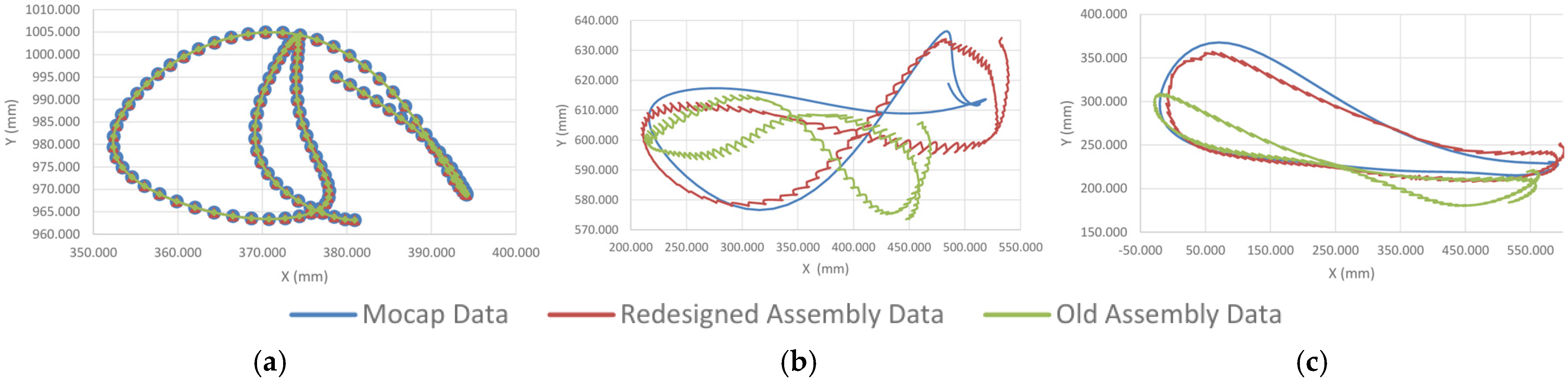
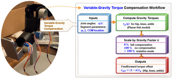
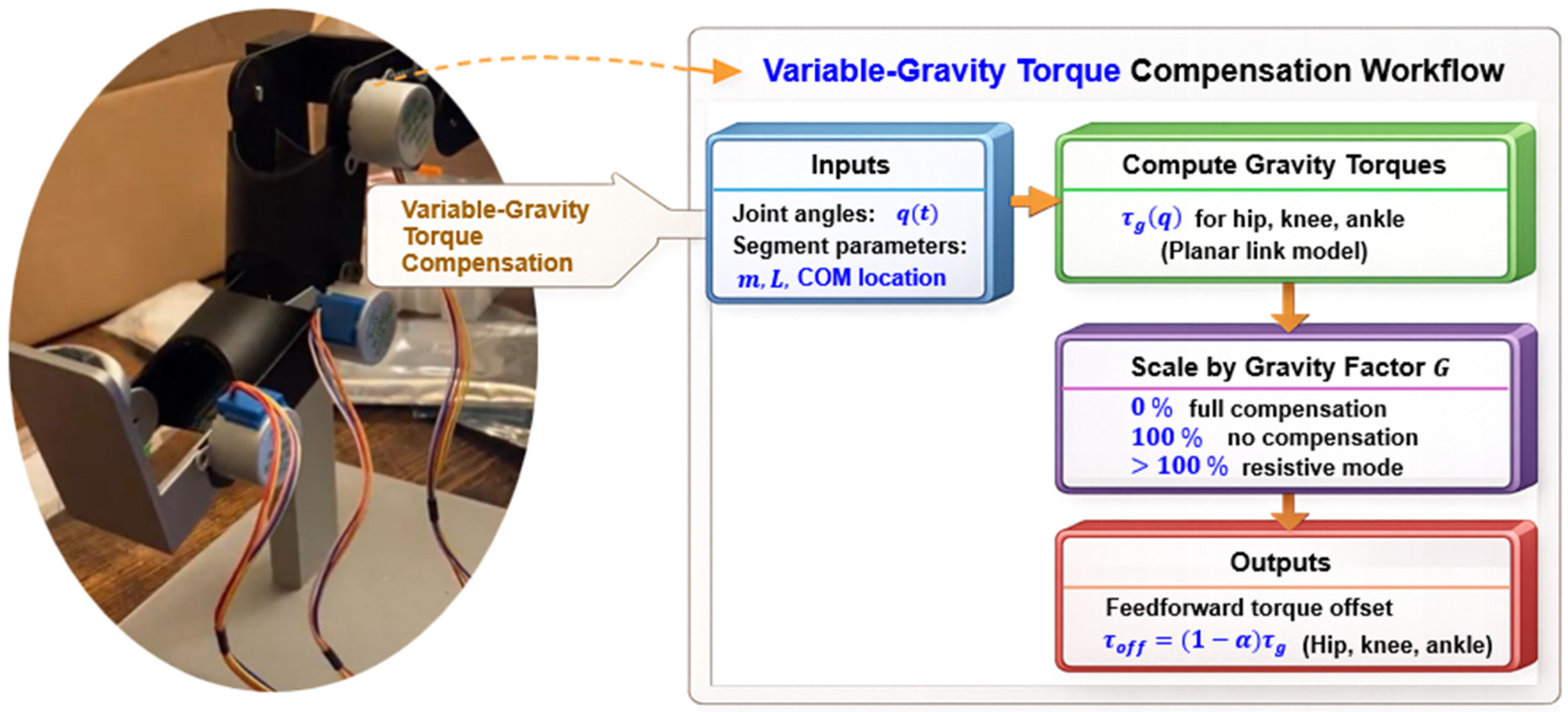
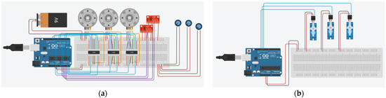
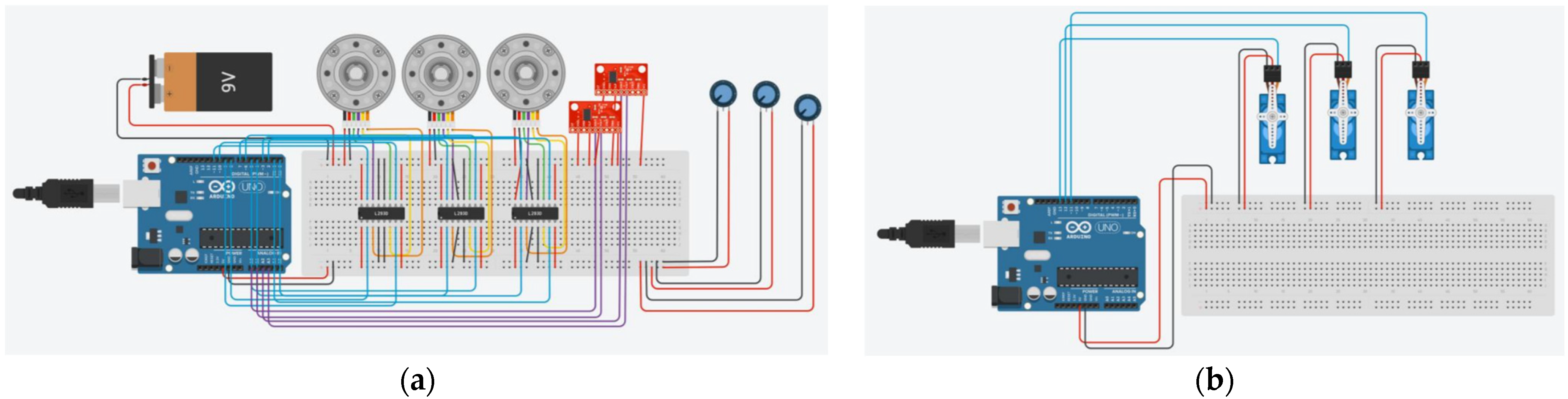
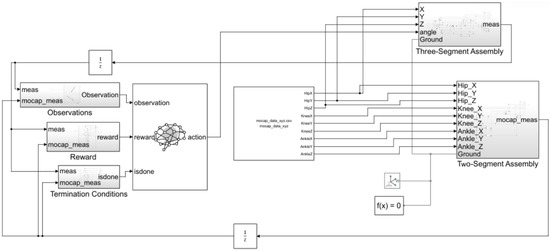
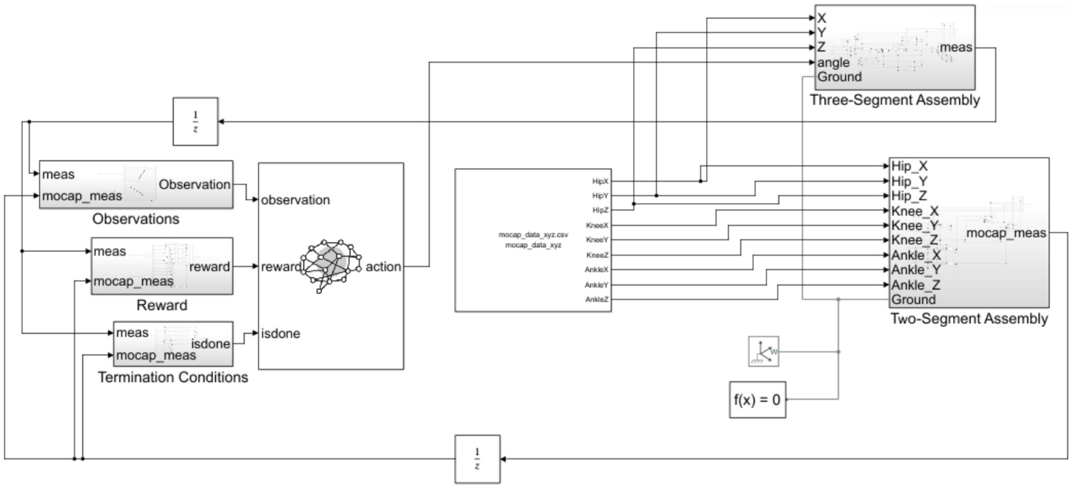
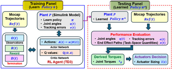
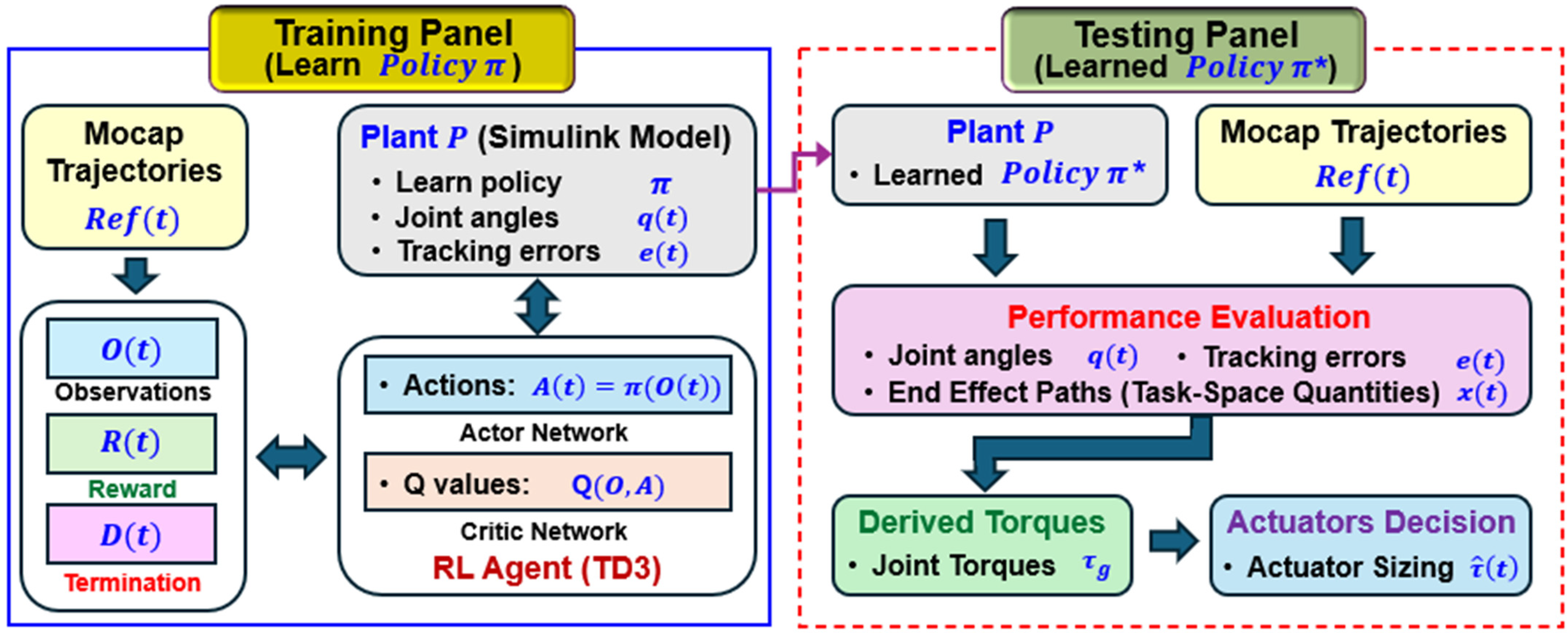
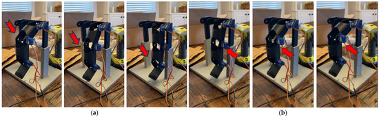
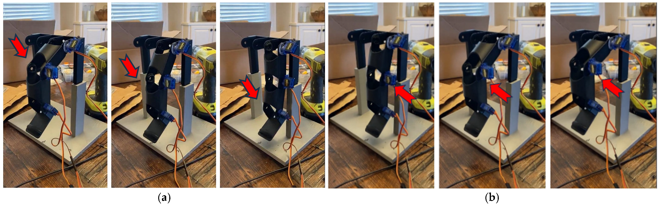

Disclaimer/Publisher’s Note: The statements, opinions and data contained in all publications are solely those of the individual author(s) and contributor(s) and not of MDPI and/or the editor(s). MDPI and/or the editor(s) disclaim responsibility for any injury to people or property resulting from any ideas, methods, instructions or products referred to in the content. |
© 2026 by the authors. Licensee MDPI, Basel, Switzerland. This article is an open access article distributed under the terms and conditions of the Creative Commons Attribution (CC BY) license.