


Abstract
This study presents an analytical investigation and a parametric evaluation of the structural behavior and seismic performance of highly corroded reinforced concrete (RC) columns, based on previously conducted experimental studies by the authors. In the analytical phase, moment–curvature relationships were obtained by considering the deterioration of the mechanical properties of both concrete and reinforcing steel due to corrosion in RC column specimens. By linking the sectional moment–curvature response with the element-level behavior observed in the experimental program, the plastic hinge lengths and rotational capacities of the corroded RC columns were determined. Subsequently, a parametric study was carried out using the analytical framework developed in the first phase on a set of 48 RC column models. In this investigation, axial load ratio, concrete compressive strength, corrosion level, section type, and concrete cover depth were considered as key parameters. The results of the combined experimental and analytical investigations demonstrate that the adopted section analysis approach successfully captures the nonlinear flexural behavior observed in the corroded specimens and provides a reliable basis for evaluating the structural performance and for supporting the assessment of seismic performance of deteriorated RC columns.
1. Introduction
Reinforcement corrosion is one of the reasons behind the deterioration of RC structures from the performance levels targeted during the design. High alkalinity of the concrete composition provides a protective layer against corrosion on the outer surface of the reinforcement. However, this protective layer deteriorates due to environmental effects such as carbonation. As a result, the reinforcement becomes vulnerable to corrosion [1], leading to deterioration in the mechanical properties of both steel and surrounding concrete. It should be noted that, in addition to generalized corrosion, localized pitting corrosion may lead to more severe and non-uniform degradation of reinforcing steel, potentially accelerating strength loss and brittle behavior. Therefore, numerous studies have been conducted in the literature to model the deterioration of mechanical properties of materials due to corrosion [2,3,4,5,6,7,8]. As the corrosion level of reinforcement increases, the volumetric expansion caused by the corrosion products accumulated as a result of the reduction in the cross-sectional area of the reinforcement causes cracking and spalling of the surrounding concrete cover. This cracking and spalling also leads to a reduction in the adherence force between the concrete and the reinforcement bars. In order to accurately predict the seismic performance levels of existing corroded RC structures, the models that take into account the changing mechanical behavior due to corrosion should be used instead of the stress–strain relationship of concrete and reinforcement used in cross-sectional analysis. This is primarily because conventional material models, which are generally calibrated for non-corroded conditions, do not adequately capture the degradation mechanisms induced by corrosion, such as cross-sectional loss, reduction in bond strength, and changes in confinement behavior. In contrast, corrosion-modified material models incorporate these deterioration effects directly into the stress–strain relationships, allowing for a more realistic representation of both stiffness degradation and energy dissipation capacity. Furthermore, previous experimental and analytical studies have demonstrated that such models provide improved accuracy in predicting the nonlinear response and ductility of corroded RC members compared to standard formulations [9,10].
Structural element behavior can be effectively represented through sectional response and moment–curvature relationships [11]. In general, the section behavior varies depending on the mechanical properties of the material, the geometry of the section and the loads acting on the section. The moment–curvature relationship of the section is also used in nonlinear analysis to calculate parameters such as rigidity, energy capacity, ductility and strength. Among these, ductility is especially critical for seismic assessment of existing structures. A review of the studies on this subject shows that in addition to the usual parameters (axial load value, reinforcement ratio, concrete’s compressive strength, different section types and dimensions), corrosion effects were also taken into account in order to determine the moment–curvature relationships of reinforced concrete structural system elements [12,13,14,15,16,17]. In addition to these studies, recent research has also investigated the seismic performance of existing reinforced concrete infrastructure under corrosion effects, demonstrating the significant impact of material degradation on structural vulnerability and seismic response [18]. Moreover, several studies have been conducted for three-dimensional modeling of corroded reinforced concrete elements using the finite element method [19,20,21,22,23]. Many uncertain parameters in the corrosion mechanism and difficulties encountered in the process of numerical modeling of corroded reinforced concrete elements have prompted researchers to adopt simplified sectional approaches that better integrate corrosion-induced degradation effects into nonlinear response prediction. Although simplified sectional approaches are advantageous in terms of computational efficiency and their ability to integrate corrosion-induced degradation effects in a more manageable manner, they are limited in capturing the full three-dimensional behavior of corroded RC elements. Full 3D FEM models, while computationally more demanding, can simulate the complex interactions between corrosion, stress redistribution, and local effects, providing a more accurate representation of the material degradation and overall response. However, due to the computational cost, simplified sectional approaches are often preferred for large-scale analysis of corroded structures.
This study extends the experimental work previously conducted by Celik et al. (2022) [24] by developing a comprehensive analytical framework and conducting an extensive parametric investigation to generalize the observed structural behavior. In this context, moment–curvature relationships were obtained at the sectional level using the XTRACT software (Version 3.0, Imbsen Software Systems, Sacramento, CA, USA) [25], incorporating corrosion-induced degradation in material properties.
Unlike previous studies that primarily focus on either experimental observations or isolated numerical modeling, this study aims to establish a direct linkage between experimentally observed behavior and analytically derived sectional response. Rather than proposing new constitutive material models, this study integrates well-established models into a unified framework and evaluates their effectiveness in capturing the nonlinear behavior of corrosion-damaged RC columns.
The combined experimental–analytical approach, together with the parametric investigation, provides new insights into the influence of corrosion on flexural performance, ductility, and energy dissipation capacity, thereby contributing to a more reliable assessment of seismic performance in deteriorated RC structures. In this respect, the novelty of this study lies in providing a direct and practically applicable bridge between sectional analysis results and performance-based structural assessment parameters such as plastic hinge length and rotational capacity.
2. Summary of the Experimental Study Done by Celik et al. (2022) [24]
The experimental program conducted by Celik et al. (2022) [24] involved reinforced concrete column specimens subjected to accelerated corrosion levels of 0.00%, 15.41%, 18.06%, 27.41%, and 28.23%, followed by displacement-controlled cyclic lateral loading. A parametric summary of the experimental program is presented in the following sections.
It should be noted that while the experimental dataset utilized in this study is based on the work of Celik et al. (2022) [24], the present study does not aim to reproduce the original experimental findings. Instead, it extends the previous work by developing a comprehensive analytical framework and conducting an extensive parametric investigation to generalize the observed structural behavior. In particular, this study establishes a direct linkage between experimentally observed responses and analytically derived sectional behavior through moment–curvature analysis, enabling a deeper understanding of corrosion-induced degradation effects on flexural performance, ductility, and energy dissipation capacity.
2.1. Material and Section Properties
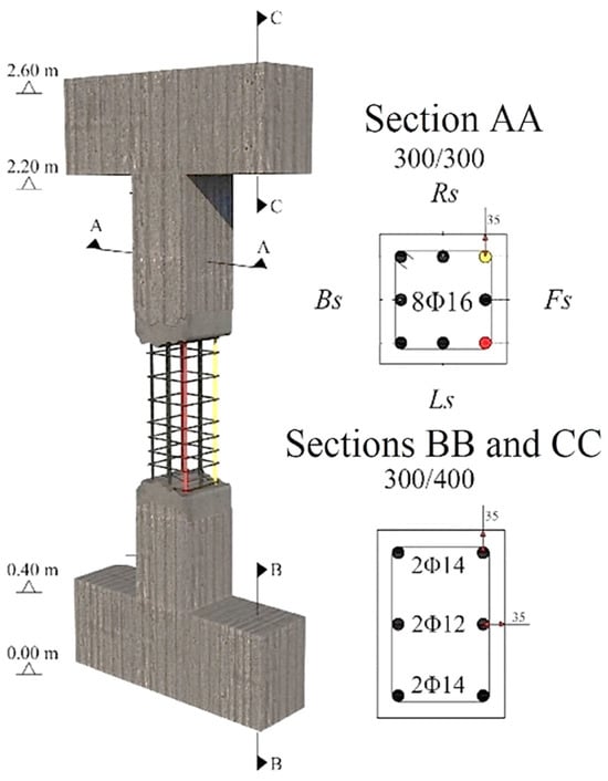
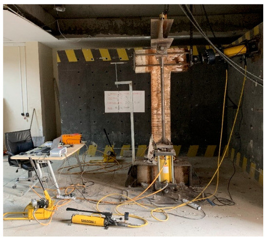
Five full-scale RC column specimens with a nominal concrete compressive strength of 15 MPa were used. The sectional dimensions and reinforcement details of the specimens are illustrated in Figure 1. The specimens had a cross-section of 30 × 30 cm and a height of 180 cm (Figure 1). The height of the column specimens from the top of the foundation to the bottom of the beam was 180 cm. A total of 8 deformed longitudinal reinforcements with a diameter of 16 mm were used in each column specimen. The reinforcement configuration was designed in accordance with TS-500 (2000) [26] by placing 8 mm diameter stirrups at 10 cm intervals at the compression zone and 15 cm intervals in the span.
Figure 1.
Sectional properties and three-dimensional model views of reinforced concrete column specimens, Celik et al. (2022) [24] (Bs, Fs, Rs, and Ls denote back side, front side, right side, and left side, respectively).
In the study done by Celik et al. (2022) [24], the mechanical properties of the steel reinforcements used in the reinforced concrete column specimens were identical, and the mechanical properties of the longitudinal reinforcements and stirrups used were determined via uniaxial tensile tests in accordance with ASTM A370 (2008) [27]. Table 1 summarizes the mechanical properties of the reinforcements obtained based on the results of the tensile tests.
Table 1.
Mechanical properties of reinforcement bars used in the RC column specimens.
It should be noted that the experimental program was conducted using a relatively low concrete compressive strength (15 MPa), which is representative of older or deteriorated reinforced concrete structures that are more susceptible to corrosion-related damage. While this may limit the direct generalization of the results to higher-strength concrete classes, the primary objective of this study is to investigate the influence of corrosion on structural behavior rather than to characterize strength-dependent performance alone. Furthermore, the analytical framework and parametric investigation developed in this study enable the extension of the findings beyond the specific experimental conditions, thereby improving the general applicability of the results.
2.2. Accelerated Corrosion Method
The accelerated corrosion method, widely adopted in experimental studies, was used to simulate and accelerate the natural corrosion process of reinforcing steel in RC elements through electrochemical effects [28,29]. In the study done by Celik et al. (2022) [24], four of the reinforced concrete column specimens produced as part of the study were corroded using the accelerated corrosion method in a full-scale copper-coated corrosion pool in Erzincan Binali Yıldırım University at the 13 March Structural Mechanics Laboratory. The initial masses of all reinforcements were measured using a precision scale to determine the actual corrosion levels of the specimens. Copper wires with a diameter of 4 mm were passed through all longitudinal reinforcements and stirrups in order to achieve a homogeneous corrosion distribution. Adjustable power supplies with a capacity of 60 volts served as anodes (positive terminals) to the copper wires extended from the reinforced concrete columns. Copper plates with a thickness of 2 mm surrounding the pool were used as negative terminals to complete the electrical circuit. The electrical current in the system was recorded on a computer every 60 s with the help of voltmeters in order to ensure controlled corrosion.
Although the accelerated corrosion setup was designed to achieve a relatively homogeneous corrosion distribution, it should be noted that, in practice, achieving perfectly uniform corrosion in reinforced concrete elements is inherently challenging. Variations in factors such as local concrete properties, bar positioning, electrical current distribution, and micro-environmental conditions can lead to non-uniform corrosion patterns. Therefore, the non-uniform corrosion observed in Section 3.1 reflects the realistic behavior of corroded reinforced concrete elements rather than a contradiction, and provides valuable insight into the variability of corrosion-induced damage.
2.3. Loading and Measurement Setup
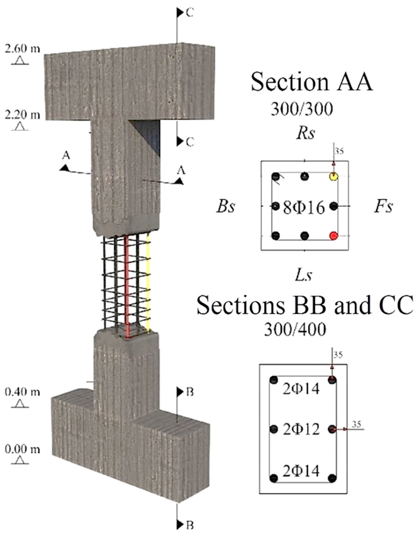
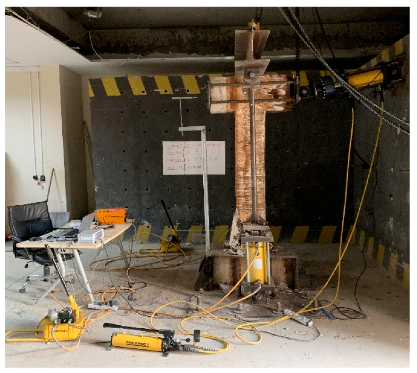
The loading and measurement setup shown in Figure 2 was designed to evaluate the seismic performance of corroded RC columns under cyclic loading. Lateral loading was applied by a hydraulic jack with a capacity of 60 tons in both push and pull directions. Axial loading was applied with 2 hydraulic jacks with a capacity of 100 tons using rigid steel profiles. The axial load rate was applied as 40% of the capacity of the column specimens. The total displacement of the column specimens was measured with the help of a Linear Variable Displacement Transducer (LVDT) with a capacity of 200 mm. The data collected during the experiment were transferred to a computer via an 8-channel data acquisition system. Incremental displacement-controlled loading was employed. The loading program was developed in accordance with FEMA 461 (2007) [30], and each displacement step was repeated for 3 loading cycles.
Figure 2.
Loading and measurement setup used to apply cyclic lateral load in the experimental study, Celik et al. (2022) [24].
3. Experimental Results
This section presents the key experimental findings on the structural behavior of corroded reinforced concrete column specimens under cyclic lateral loading. The results include corrosion distributions, load–displacement responses, energy dissipation, and ductility characteristics, along with observed damage mechanisms.
3.1. Actual Corrosion Levels
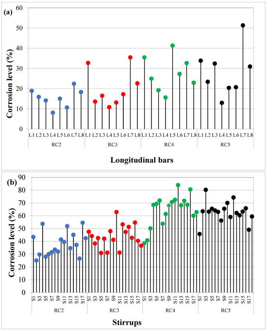
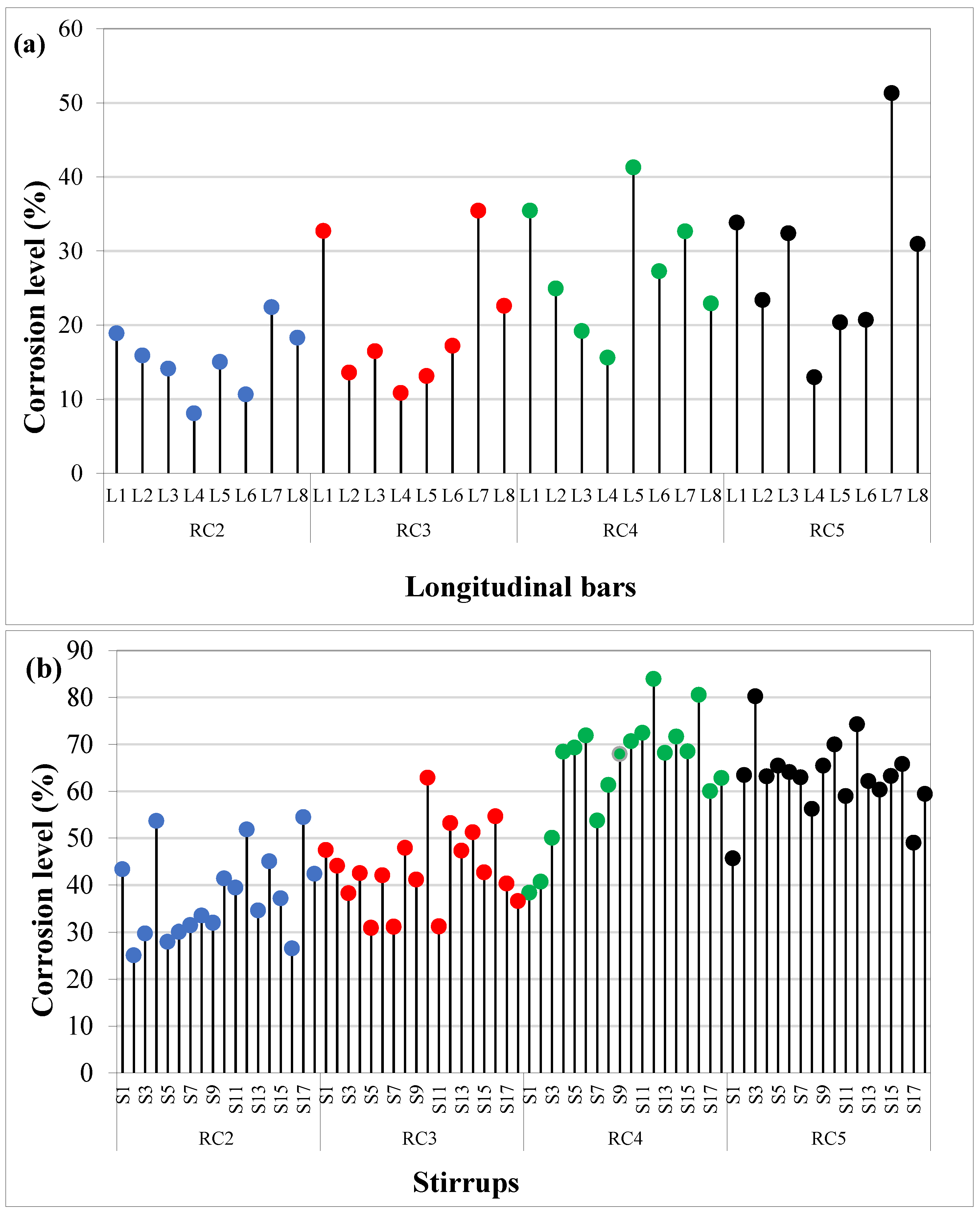
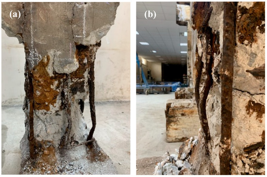
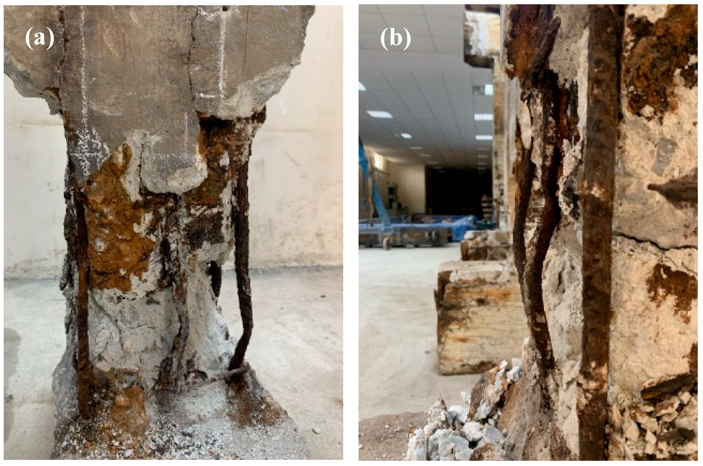
Figure 3 presents the distribution of corrosion levels in longitudinal reinforcements and stirrups. The actual corrosion levels given in Figure 3 show that there is a non-uniform distribution among the individual column specimens, longitudinal reinforcements or stirrups, which may also reflect localized corrosion tendencies under accelerated conditions. Although the same electrical current was applied to all reinforcements, variations in bar diameter influenced the corrosion distribution. On average, 8 mm stirrups exhibited approximately twice the cross-sectional loss of 16 mm longitudinal bars. This behavior can be attributed to several underlying mechanisms. First, the smaller diameter of stirrups results in a higher surface area-to-volume ratio, which makes them more susceptible to corrosion-induced mass loss under the same exposure conditions. Second, stirrups are typically located closer to the concrete surface, where the ingress of aggressive agents such as chlorides, moisture, and oxygen is more pronounced. Third, under identical electrical conditions in accelerated corrosion tests, smaller-diameter bars experience higher current density, which accelerates the corrosion rate. These combined effects explain the higher corrosion levels observed in stirrups compared to longitudinal reinforcement. This indicates a strong relationship between corrosion severity in stirrups and longitudinal bars. Therefore, the average corrosion level of longitudinal reinforcements was adopted in subsequent modeling. Post-test observations showed that high corrosion levels caused stirrup rupture and significant loss of confinement. The section losses in the stirrups significantly reduced the confinement effect in the column and led to buckling of the longitudinal reinforcements under axial load. The buckling observed in the corroded reinforcements was mostly concentrated in the plastic hinge region of the columns (Figure 4). The observed damage was consistent with the analytically predicted plastic hinge regions. These observations also provide insight into the non-monotonic variation in ductility, as the combined effects of non-uniform corrosion distribution, degradation of stirrup confinement, and localized buckling of longitudinal reinforcement influence the deformation capacity of the specimens.
Figure 3.
Corrosion level distributions in RC specimens, (a) longitudinal reinforcements, and (b) stirrups, Celik et al. (2022) [24] (Different colors represent different specimen groups (RC2, RC3, RC4, and RC5)).
Figure 4.
Buckling concentrated in the plastic hinge region of corroded reinforcement: (a) overall view of the damaged column region, and (b) detailed view showing localized buckling and section degradation (Celik et al., 2022 [24]).
3.2. Load–Displacement Relationships
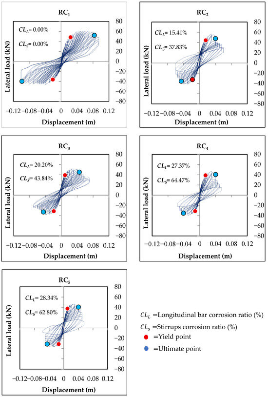
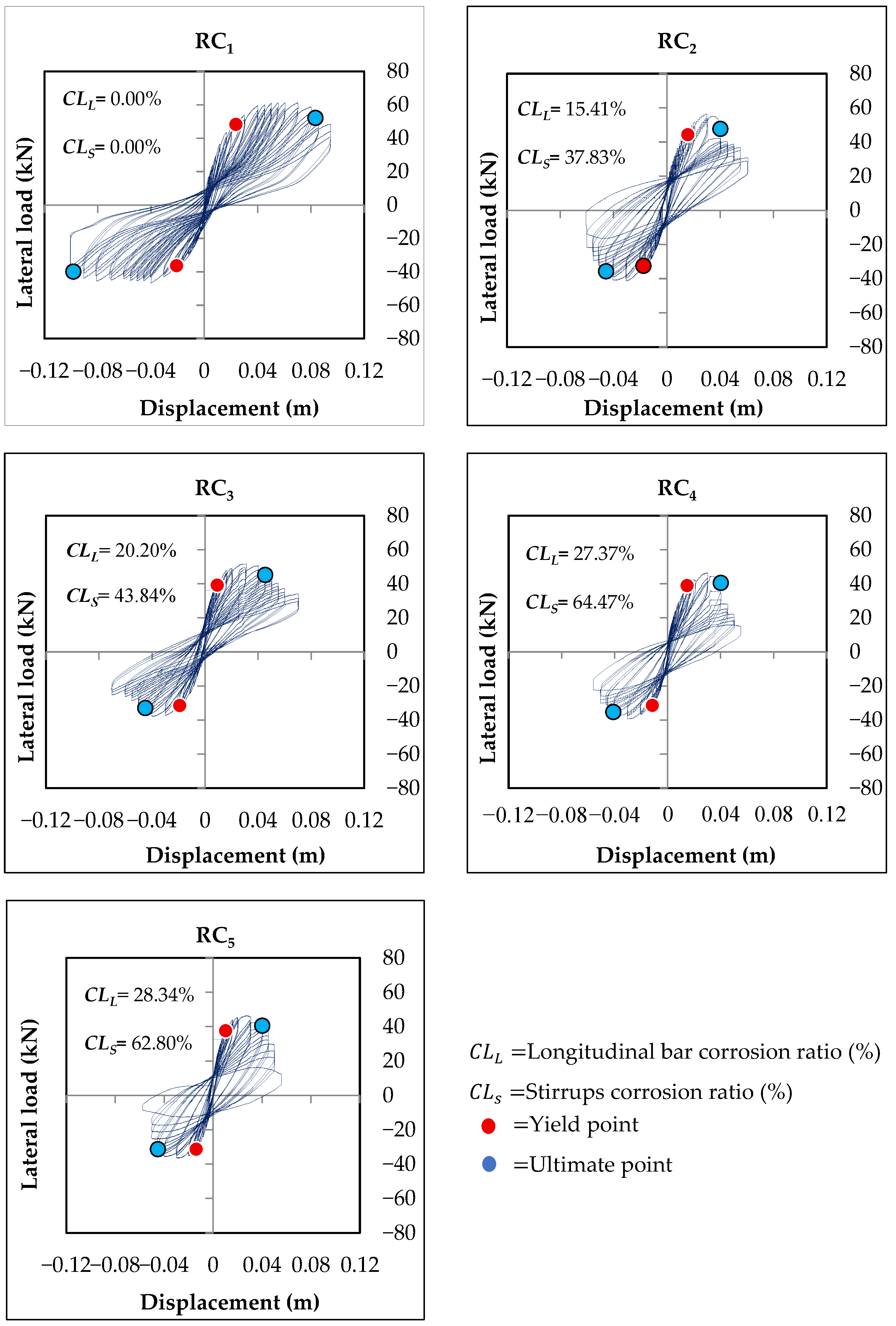
Figure 5 shows the load–displacement responses of the specimens under cyclic lateral loading. The curves were idealized following the approach proposed by Sezen and Moehle (2004) [31], with yield and ultimate points indicated. Yield and ultimate points are marked in red and blue, respectively. The displacement-based ductility values of the specimens were calculated using Equation (1).
Figure 5.
Load–displacement hysteresis curves of RC specimens under cyclic lateral loading, Celik et al. (2022) [24]. The curves correspond to the cyclic responses of each specimen (RC1–RC5).
In Equation (1), is the ultimate displacement and is the yield displacement value. It should be noted that the displacement-based ductility ratio is inherently sensitive to the definition of the yield displacement (), particularly in corroded specimens where stiffness degradation and bond deterioration may lead to a gradual transition from elastic to inelastic behavior. In such cases, the determination of may involve some level of approximation depending on the adopted idealization method.
In this study, the yield displacement was defined based on the idealization approach proposed by Sezen and Moehle (2004) [31], which provides a consistent and widely accepted basis for comparison. Although different definitions of may lead to variations in the calculated ductility ratios, the overall trends observed in the experimental results remain consistent. Therefore, the interpretation of ductility results has been carried out with consideration of these limitations.
In Table 2, the results indicate that the average displacement-based ductility decreased compared to the reference specimen; however, no clear correlation was observed between corrosion level and ductility. In some cases, higher corrosion levels resulted in increased ductility values, primarily due to reduced bond and stiffness, which led to earlier yielding and lower yield displacement ().
Table 2.
Results from the experimental study of Celik et al. (2022) [24].
The non-monotonic variation in displacement-based ductility with increasing corrosion level can be attributed to the definition of the ductility ratio itself, which depends on both the ultimate displacement and the yield displacement. In corroded specimens, deterioration of bond characteristics and stiffness may lead to earlier yielding, thereby reducing the yield displacement. As a result, even when the ultimate deformation capacity is reduced due to corrosion-induced damage, the displacement-based ductility ratio may remain unchanged or even increase in some cases. Therefore, the observed increase in ductility in certain specimens should not be interpreted as an improvement in structural performance, but rather as a consequence of the reduced yield displacement and the limitations of displacement-based ductility in representing the actual deformation capacity of corroded RC members. This interpretation is also consistent with the observed confinement loss, localized buckling, and non-uniform corrosion effects in the test specimens.
Accordingly, displacement-based ductility alone may not always provide a fully reliable measure of the deformation capacity of corroded RC members. For this reason, the ductility results should be interpreted together with energy dissipation capacity and observed damage mechanisms. It should also be noted that displacement-based ductility alone may not fully represent the actual deformation capacity of corroded RC members, as it is highly sensitive to the definition of yield displacement. Therefore, the observed non-monotonic behavior should be interpreted with caution and in conjunction with other performance indicators.
4. Analytical Study
Moment–curvature relationships were established to investigate the cross-sectional behavior of corroded RC columns under flexural loading with varying corrosion levels. The section dimensions were 30 × 30 cm with a concrete cover of 3.5 cm. The stress–strain relationships of both confined and unconfined concrete were defined as functions of corrosion level. The analyses incorporated corrosion-induced reductions in reinforcement diameter and mechanical properties into nonlinear material models. The analytical model parameters are derived from established mechanics-based formulations, and these parameters serve as the foundation for the nonlinear material models used in this study.
In the analytical study, the XTRACT software (Version 3.0) [25] was chosen for its ability to employ fiber discretization, a technique that allows for the detailed modeling of corroded RC elements. This is particularly beneficial for capturing localized corrosion effects that influence the behavior of reinforced concrete members under flexural loading. In this model, the cross-section is divided into fibers, each representing a small portion of the section, with material properties assigned to each fiber based on the level of corrosion.
To ensure the accuracy and precision of the moment–curvature relationships, the fiber discretization approach is complemented by a convergence criterion of 0.01% for force and displacement at each loading step. This dual approach allows for both the detailed modeling of corrosion effects and the reliable convergence of the numerical solution. The fiber discretization is set to 10 segments per section for accurate representation of stress–strain relationships, especially in the presence of localized corrosion effects. This approach allows for precise modeling of the nonlinear behavior of corroded RC elements under flexural loading.
4.1. Concrete Model
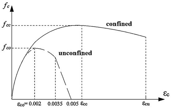
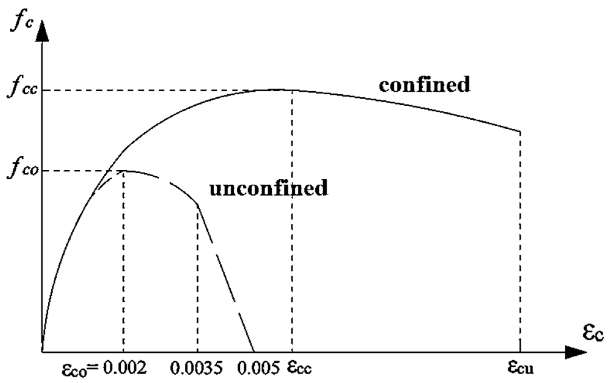
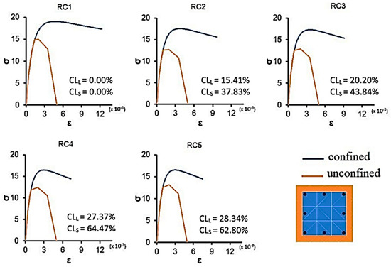
The stress–strain relationships of confined and unconfined concrete were defined according to the Turkish Building Seismic Code (TBEC, 2018) [32] (Figure 6).
Figure 6.
Stress–strain relationship of the confined and unconfined concretes.
Although there are widely used models such as Mander et al. (1988) [33] and Kent–Park (1971) [34], the TBEC (2018) [32] model was selected for this study due to its practical applicability for reinforced concrete under seismic loading, as outlined in the Turkish Building Seismic Code. While models such as Mander and Kent–Park [33,34] are widely used, the TBEC model was chosen because it provides a more direct alignment with the seismic design provisions and material property adjustments in the Turkish context. Moreover, TBEC [32] allows for an easier incorporation of corrosion-induced material degradation effects, which is a crucial aspect of this study.
Although Mander and Kent–Park [33,34] models are more commonly used for capturing the behavior of unconfined and confined concrete, they were not selected for this study due to their limitations in representing the effects of corrosion, particularly under advanced corrosion conditions. The TBEC model [32], while primarily developed for shear-related behavior, provides a practical and internally consistent representation of confinement behavior in corroded concrete. Its flexibility in adjusting for degradation in material properties due to corrosion made it a more suitable choice for evaluating the global structural response of corroded RC columns.
It is acknowledged that the TBEC model [32] does not explicitly account for non-uniform corrosion distribution or the degradation of bond strength between stirrups and concrete. However, given the lack of widely accepted formulations that address these coupled effects consistently, the TBEC model [32] offers a practical approximation for the purposes of this study.
The compressive stress in confined concrete () is calculated by Equation (2). In Equation (2), represents the strain-dependent variable, and r represents the elastic modulus-dependent variable.
The relationship between confined and unconfined concretes is shown in Equation (3). To determine the relationship between these parameters, the constant coefficient should be calculated by Equation (4). The effective confining stress () value is calculated with Equation (5) for rectangular sections.
The value specified in Equation (5) represents the confining effectiveness coefficient, and denote the transverse reinforcement ratios in the x and y directions, respectively, and represents the yield strength of the stirrups. Equation (6) is used to calculate the coefficient .
In Equation (6), represents the distance between the centers of the vertical reinforcement surrounding the section, and denote the dimensions measured along the axes of the transverse reinforcement surrounding the confined concrete, s represents the transverse reinforcement spacing, and represents the longitudinal reinforcement area in the section. Using Equations (7) and (8), the relationship between the x and r parameters given in Equation (2) can be calculated.
The maximum strain developed in the concrete in the confined section is calculated with Equation (9).
For corroded RC columns, modified material models were adopted to account for degradation effects, following the approach of Turan et al. (2024) [35]. The reduction in compressive strength of unconfined concrete was calculated using the model proposed by Vecchio and Collins (1986) [36], based on crack width.
It should be noted that the model proposed by Vecchio and Collins (1986) [36] was originally developed to account for strength reduction due to cracking in reinforced concrete, rather than specifically for corrosion-induced cracking. However, in the context of corrosion-damaged concrete, crack formation caused by the expansion of corrosion products leads to similar degradation mechanisms, particularly in terms of crack-induced loss of compressive strength.
Therefore, the adoption of this model in the present study is based on the assumption that corrosion-induced cracking can be represented in a manner analogous to mechanically induced cracking. While this approach provides a practical and consistent means of incorporating crack-related strength degradation into the analysis, its limitations in capturing corrosion-specific phenomena are acknowledged. Furthermore, it should be emphasized that corrosion-induced cracking is inherently a progressive and evolving process under loading. However, within the scope of this study, the use of experimentally measured average initial crack widths () provides a practical and consistent representation of the initial damage state, while acknowledging that the evolution of crack width during loading is not explicitly captured in the present analytical formulation.
In Equation (10), and are the ultimate compressive strength of unconfined concrete after and before corrosion, respectively. The constant in Equation (10) was suggested as 0.1 by Cape (1999) [37], which depends on the reinforcement diameter and roughness. In this study, the value = 0.1 was adopted directly to maintain consistency with the original formulation and to ensure comparability with previous studies. It is recognized that this parameter may vary depending on material properties, corrosion conditions, and cracking characteristics; however, the present work focuses on evaluating the global structural response using a consistent analytical framework rather than recalibrating material-level parameters. In Equation (10), represents the strain value corresponding to the maximum stress value in the concrete, and represents the average strain value in the cracked section in the pressure direction, and this value is calculated using Equation (11). The formulation of and its dependence on crack width () follow the original expressions proposed in the literature and are adopted here to ensure consistency with established modeling approaches.
It should be noted that the analytical results are inherently sensitive to the crack width (), as this parameter directly influences the reduction in compressive strength through Equations (10) and (11). Variations in crack width may lead to corresponding changes in the estimated material properties and, consequently, the predicted structural response.
However, in the present study, values were obtained from experimental measurements, which reduces the uncertainty associated with this parameter. Therefore, the adopted approach reflects realistic crack conditions observed in the tested specimens rather than relying on assumed values.
Furthermore, the primary objective of the analytical model is to evaluate the global structural response of corroded RC columns. Within this scope, the use of average measured crack widths provides a practical and consistent basis for analysis, while acknowledging that local variations in crack width may introduce additional variability that is not explicitly captured in the present formulation.
In the calculation of the () value in Equation (11), the crack width in the non-corroded section and the crack width caused by corrosion are taken into account. In the calculation of () values, the experimentally obtained primary corrosion crack width () values were considered. Table 3 shows the average initial corrosion crack widths measured along the height of the RC columns.
Table 3.
Average initial corrosion crack widths.
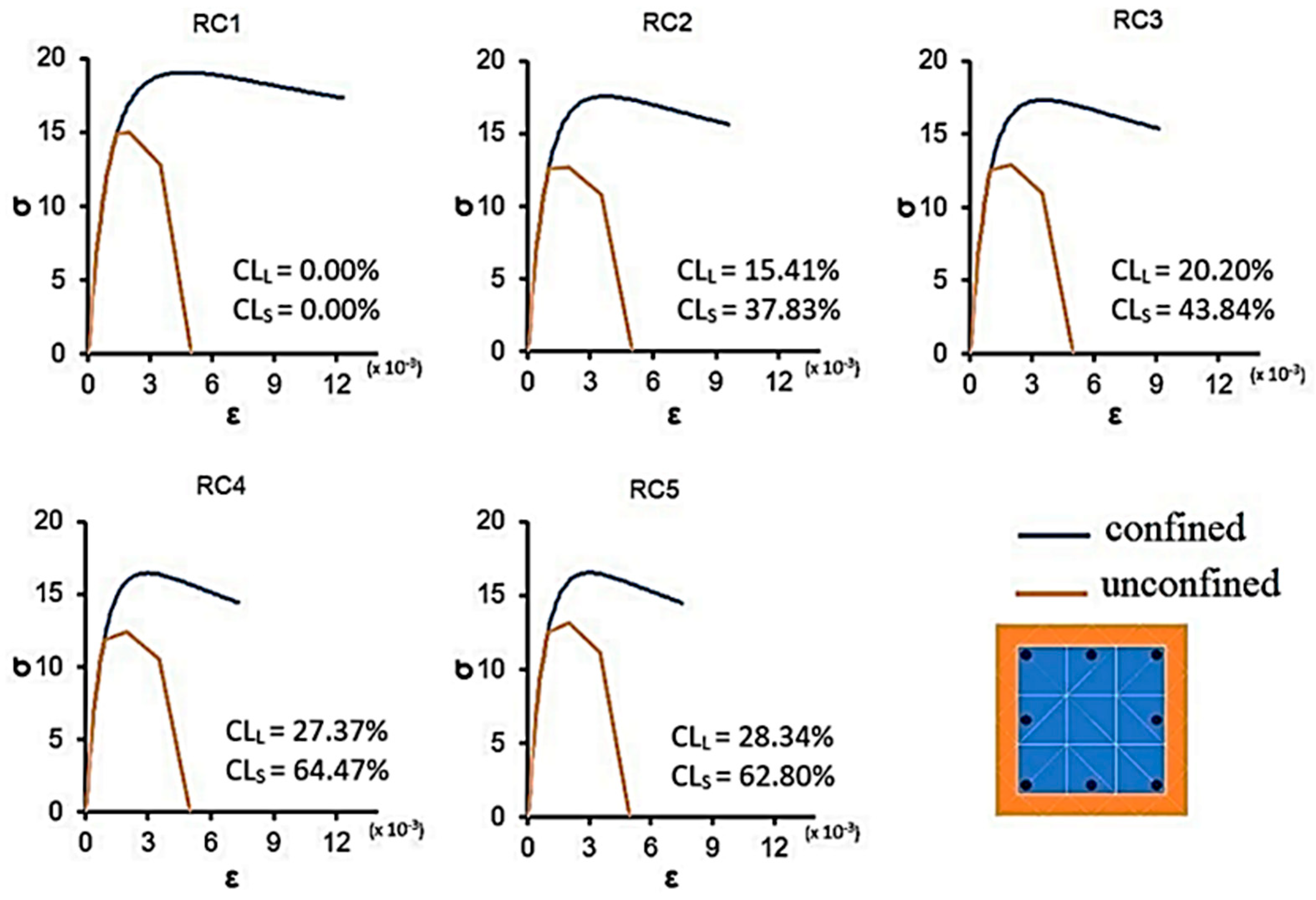
After calculating the reductions in compressive strength due to the formation of cracks caused by the corrosion product accumulated in the concrete cover, the reinforcement ratios in Equation (2) were calculated for each specimen by considering the average section loss in the stirrups. Based on these values, a confined concrete model was developed for the corroded RC sections. The confined and unconfined concrete models used for the corroded reinforced concrete columns are shown in Figure 7, and their mechanical properties are summarized in Table 4, along with the corresponding corrosion levels.
Figure 7.
Confined and unconfined corroded concrete models.
Table 4.
Mechanical properties of corroded concretes.
While the model was originally developed for shear-related behavior, it is adopted here as a practical approximation to account for crack-induced strength degradation in corroded concrete, and its limitations are acknowledged. In addition, it should be noted that the present formulation considers the average cross-sectional loss of stirrups and does not explicitly account for non-uniform corrosion distribution or bond degradation between stirrups and surrounding concrete. These factors may reduce the effective confinement provided by transverse reinforcement, particularly under advanced corrosion conditions. However, due to the lack of widely accepted analytical formulations that consistently incorporate these coupled effects, the adopted approach provides a practical and internally consistent representation of confinement behavior within the scope of this study. Therefore, the use of average corrosion levels in this study should be interpreted as a simplified but practical representation of the global response, and it does not aim to capture localized pitting effects at the material level.
4.2. Reinforcement Model
The mechanical properties of reinforcement were based on tensile test results obtained from the reference (non-corroded) specimen (see Table 1). Corrosion-induced pitting leads to non-uniform section loss, adversely affecting mechanical properties and potentially causing premature failure (Frankel, 1998) [38]. It is recognized that such localized corrosion effects may significantly influence strength degradation and ductility reduction. However, accurately incorporating pitting corrosion into analytical modeling remains challenging due to the lack of widely accepted constitutive relationships and consistent experimental calibration data. Therefore, empirical models relating corrosion level to mechanical properties were adopted [39,40], which provide a practical and consistent representation of corrosion-induced degradation within the scope of this study. However, previous studies have demonstrated that corrosion in reinforcement is often highly non-uniform and dominated by localized pitting, which may lead to more severe strength degradation and brittle failure modes (e.g., Crespi et al., 2022) [41]. Despite this, the present study adopts an average corrosion level to represent the overall material degradation, as the primary objective is to evaluate the global structural response rather than local damage mechanisms. The decreases in yield and elastic modulus of the reinforcement due to corrosion were calculated according to the models proposed by Wang and Liu (2008) [42] (Equations (12) and (13)). The ultimate stress and strain values were calculated using the models of Wu and Yuan (2008) [43] (Equations (14) and (15)).
Neglecting localized pitting corrosion in the analytical modeling may lead to an underestimation of the severity of strength degradation and ductility loss, as pitting can cause stress concentration and premature fracture of reinforcement bars. In particular, localized section loss due to pitting may result in earlier yielding or brittle failure that is not fully captured by models based on average corrosion levels.
However, since the primary objective of this study is to evaluate the global structural response of corroded RC columns, the use of average corrosion levels is considered acceptable within this context. The adopted approach provides a reasonable representation of overall degradation, while acknowledging that local effects associated with pitting may lead to more critical behavior in practice.
The actual corrosion levels were determined using the gravimetric method (Section 3.1) and used to define the mechanical properties of each reinforcement bar based on Equations (12)–(15). The strain corresponding to strain hardening was assumed as one-tenth of the ultimate strain. The resulting mechanical properties are summarized in Table 5.
Table 5.
Mechanical properties of reinforcing steel bars after corrosion-induced cross-section loss.
It should be noted that the empirical models proposed by Wang and Liu (2008) [42] and Wu and Yuan (2008) [43] were originally developed based on experimental observations of corroded reinforcement over a range of corrosion levels that are comparable to those considered in the present study. Therefore, their application is considered appropriate for representing the degradation of mechanical properties within the investigated corrosion range.
However, it is also recognized that these models are derived from specific experimental datasets and may not fully capture all aspects of corrosion-induced variability, particularly in cases of highly localized pitting corrosion or extreme corrosion levels. Despite these limitations, the adopted models provide a practical and widely accepted framework for incorporating corrosion-induced degradation into analytical simulations.
In the context of this study, the use of these models is intended to ensure consistency with established approaches in the literature while enabling a reliable evaluation of the global structural response of corroded RC columns.
5. Analytical Results
This section presents the analytical results obtained from sectional analyses of corroded reinforced concrete members. The influence of reinforcement corrosion on flexural performance, ductility, energy dissipation, and rotational capacity is evaluated under combined axial and lateral loading. The analytical results are compared with experimental findings to validate the proposed modeling approach. It should be noted that the experimental results are used solely for comparison purposes and not for calibration of the analytical model.
5.1. Moment–Curvature Relationships
Section analyses were conducted to evaluate the influence of reinforcement corrosion on RC sections under axial load and flexural moment. Corrosion-induced reductions in concrete strength and confinement were incorporated using empirical models (Section 4.1), while degraded reinforcement properties were included based on Section 4.2.
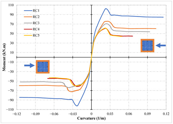
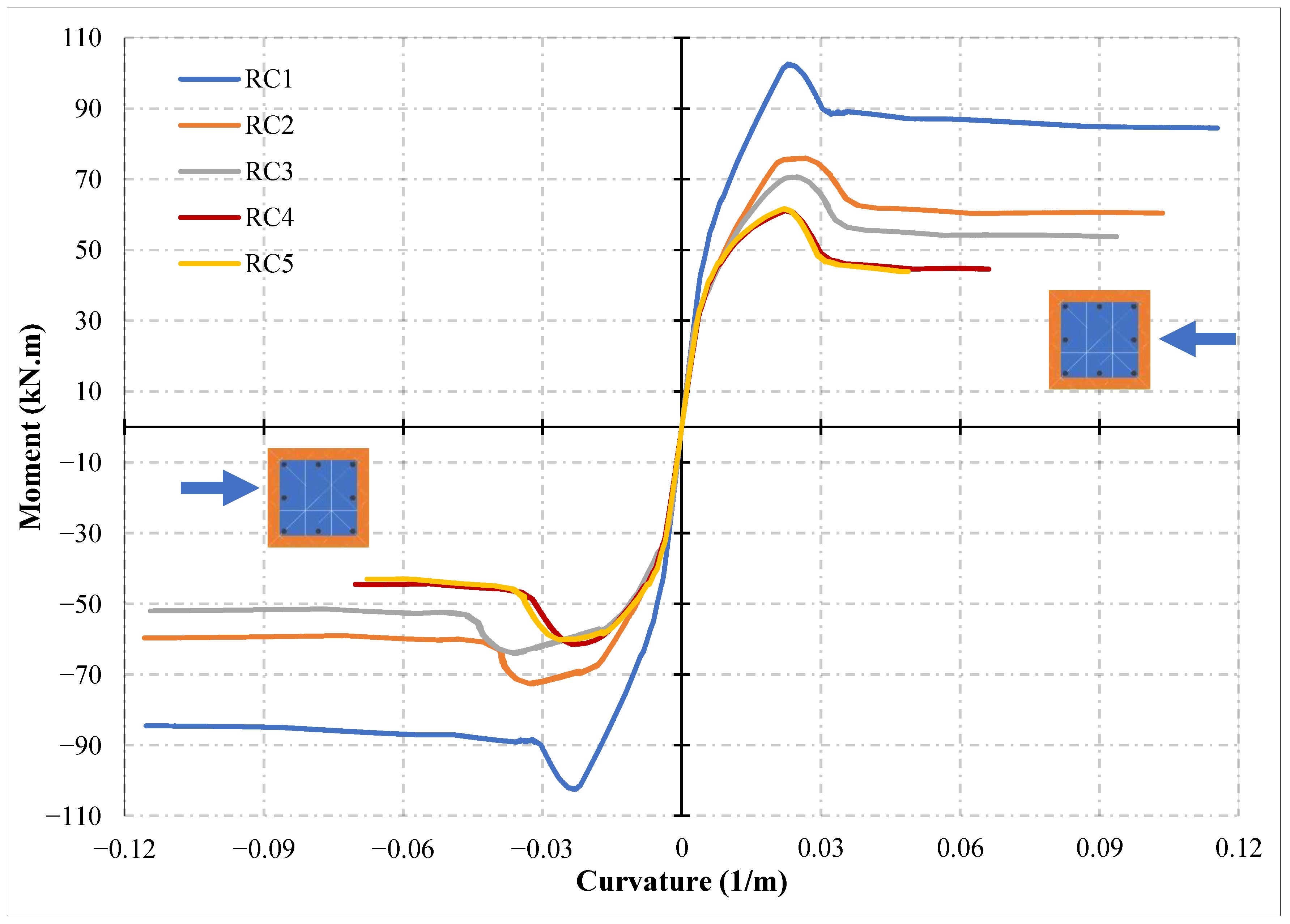
The moment–curvature relationships obtained under an axial load ratio of 40% are presented in Figure 8 and summarized in Table 6.
Figure 8.
Moment–curvature responses of RC sections under an axial load ratio of 40%, showing the effect of corrosion level (The arrows indicate the representative cross-sectional states corresponding to the response curves).
Table 6.
Results of the analytical study.
It should be noted that the moment–curvature relationships employed in this study are based on monotonic loading and do not explicitly account for cyclic degradation effects such as stiffness deterioration, strength loss, or pinching behavior. However, moment–curvature analysis provides a reliable representation of the sectional backbone response, which governs the flexural capacity and deformation characteristics of reinforced concrete members. Therefore, despite the cyclic nature of the experimental loading protocol, the adopted approach is considered adequate for evaluating the global structural behavior and comparing the relative influence of corrosion on sectional performance. Accordingly, the limitations of this assumption are explicitly acknowledged, and the results should be interpreted as representing the sectional backbone behavior rather than the full cyclic hysteretic response.
An analysis of the moment–curvature relationships given in Figure 8 and Table 6 shows that with the increase in corrosion level, compared to the non-corroded reference section:
- The results indicate that increasing corrosion levels lead to a consistent reduction in moment capacity in both loading directions, as reflected by decreases in yield moment (), ultimate moment (), and corresponding curvature values ().
- No significant change in initial stiffness was observed up to the cracking stage; however, the influence of corrosion became more pronounced after cracking of the outer concrete fibers.
The limited variation in initial stiffness can be attributed to the fact that this stage of the response is primarily governed by the elastic properties of the concrete and the uncracked section behavior. At low load levels, the contribution of reinforcement is relatively limited, and the effects of corrosion-induced degradation, such as bond deterioration and cross-sectional loss, are not yet fully activated.
Corrosion effects become more pronounced after cracking of the concrete and the onset of nonlinear behavior, where bond degradation, reduced reinforcement area, and stiffness loss significantly influence the structural response. Therefore, the observed similarity in initial stiffness across different corrosion levels is consistent with the mechanics of reinforced concrete behavior and does not contradict the expected influence of corrosion at later stages. This observation is also consistent with the experimental results, where the influence of corrosion on stiffness and strength becomes more evident after cracking, particularly in terms of bond degradation, localized damage, and reduced load-carrying capacity.
- 3.
- Similar to the experimental observations, no clear correlation was identified between corrosion level and curvature-based ductility. This behavior can be attributed to the early yielding of corroded reinforcement due to degradation in mechanical properties.
- 4.
- In contrast, energy dissipation capacity showed a clear decreasing trend with increasing corrosion levels, with values reducing from 4.74 to 1.45 kN/m2 as corrosion increased. This observation suggests that energy-based parameters may provide a more consistent and physically meaningful measure of structural performance in corroded RC members compared to conventional ductility definitions. Accordingly, the interpretation of ductility behavior in corroded RC members should be supported by multiple performance indicators rather than relying solely on displacement-based measures.
- 5.
- Additionally, higher energy absorption was observed in the negative loading direction, likely due to the non-uniform distribution of corrosion along longitudinal reinforcement, which may also reflect localized degradation effects.
The moment-carrying capacities found in the experimental and analytical studies are given in Table 7, together with the loading direction and corrosion levels.
Table 7.
Comparison of experimental and analytical moment results.
To provide a quantitative assessment of the analytical model accuracy, the ratio of analytical to experimental moment capacity () was evaluated for all specimens. The results indicate that the mean ratio is close to unity, with limited dispersion across different corrosion levels and loading conditions.
The analytical model generally provides slightly conservative predictions, with most values falling below or close to 1.0. The observed variability reflects the influence of corrosion-induced uncertainties, including non-uniform section loss and bond degradation, which are not fully captured in the analytical formulation.
In addition, the analytical results are inherently sensitive to key input parameters, particularly the crack width () used in the concrete strength reduction model and the corrosion-dependent reduction in reinforcement mechanical properties. Variations in these parameters may lead to noticeable changes in the predicted moment capacity. The use of average corrosion levels for reinforcement properties, instead of explicitly modeling localized pitting corrosion, may further contribute to discrepancies between analytical and experimental results. Localized corrosion can lead to stress concentrations, premature yielding, and brittle failure mechanisms that are not fully represented in the current modeling framework. Therefore, the observed deviations, particularly under high corrosion levels, can be attributed to the combined influence of parameter sensitivity and the limitations of representing complex localized damage mechanisms through averaged material properties.
Overall, the agreement between analytical and experimental results demonstrates that the proposed model provides a reasonably accurate and consistent representation of the flexural behavior of corroded RC columns.
The mean value of is approximately 0.90–0.95, with a standard deviation of about 0.10–0.15.
5.2. Plastic Hinge Lengths and Rotational Capacities
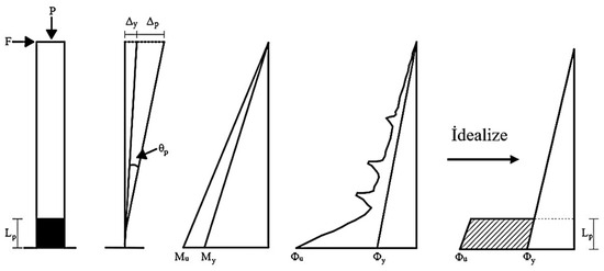
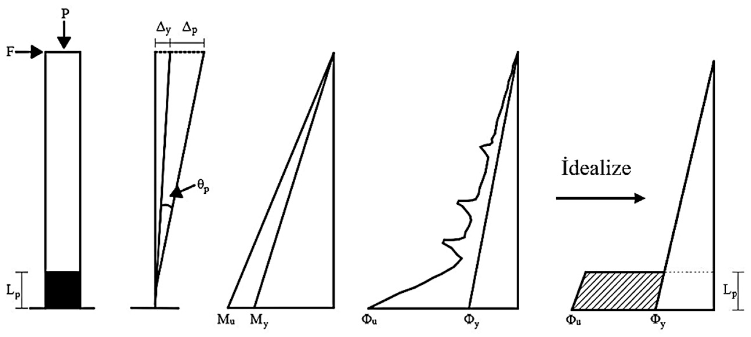
Flexural behavior in RC sections is represented by curvature, which governs the rotational and displacement response of structural elements (Figure 9). In the lumped plasticity approach, inelastic deformations are assumed to concentrate within the plastic hinge region near the maximum moment zone. This behavior is also reflected in Table 8, where severely corroded specimens exhibit plastic hinge lengths comparable to the reference specimen. This indicates that the plastic hinge length does not follow a strictly monotonic trend with increasing corrosion level, but is governed by competing mechanisms such as bond degradation, confinement loss, and redistribution of inelastic deformations.
Figure 9.
Moment–curvature diagram of the reinforced concrete columns.
Table 8.
Plastic hinge lengths and rotation values.
Rotation and displacement values can be calculated using the moment–area theorem based on the idealized curvature distribution. The rotation (, ) and peak displacement (, ) relations found using the moment–area theorem for a cantilever reinforced concrete column are given in Equations (16)–(19).
Yield State:
Ultimate State:
where is the curvature at the yield state, is the peak displacement at the yield state, is the curvature at the ultimate state and is the peak displacement at the ultimate state.
Table 8 shows the plastic hinge lengths and rotation values of corroded reinforced concrete columns calculated by the moment–field theorem using the moment–curvature relations obtained from the analytical study and the load–displacement relations obtained from the experimental study.
It should be noted that the plastic hinge length and rotation formulations adopted in this study are based on simplified moment–area relationships. However, the input parameters used in these formulations, particularly the yield and ultimate curvature values, are directly derived from moment–curvature analyses that incorporate corrosion-induced material degradation. Therefore, the influence of corrosion is implicitly reflected in the calculated plastic hinge properties. While the simplified approach does not explicitly account for localized damage mechanisms such as bond deterioration or non-uniform corrosion distribution, it provides a consistent and practical framework for comparative evaluation of damaged and non-damaged sections within the scope of this study.
As shown in Table 8, the plastic hinge lengths expected to occur in the maximum moment zone of the member according to the lumped plastic behavior model are shorter in the corroded columns than in the reference specimen, but the plastic hinge lengths of corroded columns do not exhibit a monotonic increase with corrosion level. In other words, the length of the area where plastic deformations are concentrated increased with increasing corrosion level. The plastic hinge lengths of the reinforced concrete columns at corrosion levels of 0.00%, 15.41%, 20.20%, 27.37% and 28.34% were calculated as 0.43 m, 0.17 m, 0.22 m, 0.28 m and 0.42 m, respectively.
The elastic rotation of the corroded reinforced concrete columns decreased with increasing corrosion level, while the plastic rotation of the corroded reinforced concrete columns increased. The corroded sections reach the yield state earlier as a result of the deterioration in the mechanical properties of reinforcements due to corrosion. Therefore, the elastic rotation of the columns decreases as the corrosion level increases, and thus the plastic rotation increases in corroded reinforced concrete columns that reach the yield state earlier. The ratio of plastic rotation to total rotation of the reinforced concrete column sections at corrosion levels of 0.00%, 15.41%, 20.20%, 27.37% and 28.34% were found to be 76%, 51%, 61%, 64%, and 78%, respectively, showing a nonlinear trend with corrosion level.
The variation in plastic hinge length with corrosion level is nonlinear rather than monotonic. This non-monotonic behavior can be explained by the interaction of multiple degradation mechanisms. At moderate corrosion levels, the reduction in bond strength and initial stiffness leads to a more localized inelastic response, resulting in shorter plastic hinge lengths. However, at higher corrosion levels, the combined effects of severe bond deterioration, reduced confinement due to stirrup corrosion, and distributed buckling of longitudinal reinforcement lead to a spread of inelastic deformations along a larger region. Compared with the reference specimen, moderate corrosion levels resulted in shorter plastic hinge lengths, whereas severe corrosion caused the plastic hinge region to expand again due to the combined effects of bond degradation, reduced confinement caused by stirrup corrosion, and more distributed buckling of longitudinal reinforcement. In some cases, severely corroded specimens exhibited plastic hinge lengths comparable to the reference specimen, indicating that the relationship between corrosion level and plastic hinge length is governed by multiple interacting mechanisms. This observation suggests that the plastic hinge region may expand again at higher corrosion levels due to the redistribution of plastic deformations, rather than remaining localized. Therefore, although general trends can be identified, the available dataset does not support the development of a simplified predictive formulation for direct engineering application. Although corrosion generally reduces strength and ductility, it may also lead to a more distributed plastic response, which explains the observed increase or recovery in plastic hinge length under severe corrosion conditions. This behavior highlights the importance of considering competing mechanisms governing the spatial distribution of inelastic deformations in corroded RC members.
It should be emphasized that the available dataset is limited and does not provide a sufficient basis for developing generalized empirical or semi-empirical predictive relationships for plastic hinge length. The observed non-monotonic behavior suggests that the variation in plastic hinge length is governed by multiple interacting mechanisms, including bond deterioration, confinement loss, and redistribution of inelastic strains. Therefore, the results presented in this study should be interpreted as indicative of underlying behavioral trends rather than as a basis for simplified predictive formulations.
6. Parametric Study
In addition to the validation study, a comprehensive parametric analysis was conducted on 48 RC section configurations to evaluate the influence of key variables on structural behavior. The investigated parameters included axial load ratio (20%, 40%), compressive strength (8 MPa, 30 MPa), corrosion level (15%, 40%), section type (rectangular, circular), and concrete cover thickness (25 mm, 40 mm). The developed analytical approach (Section 4) was used for all models. The configuration and results are summarized in Table 9 and Table 10. It should be noted that the parametric study is based on average corrosion levels and does not explicitly account for the non-uniform corrosion distribution, including potential localized corrosion effects, which may influence confinement behavior, particularly at higher corrosion levels. All sections considered in the parametric study have a constant cross-sectional dimension of 30 × 30 cm and reinforcement details consistent with those defined in the experimental program (Section 2), unless otherwise specified. For circular sections, equivalent cross-sectional areas and reinforcement ratios were adopted to maintain consistency with the reference rectangular sections, ensuring that the influence of geometry could be isolated in the parametric evaluation.
Table 9.
Configurations of RC sections analyzed in the parametric study.
Table 10.
Results of the parametric study.
For both rectangular and circular sections, confinement effects were modeled using the same constitutive framework described in Section 4, particularly the concrete model defined in Section 4.1. The confinement parameters were calculated based on the geometry-specific transverse reinforcement configuration, ensuring that the effects of confinement were incorporated in a consistent manner across different section types.
For circular sections, equivalent transverse reinforcement ratios and effective confinement parameters were defined to maintain consistency with the rectangular sections, while accounting for geometric differences in confinement effectiveness. This approach allows for a meaningful comparison between section types, although it is acknowledged that idealized confinement models may not fully capture all local variations in confinement behavior, particularly under severe corrosion conditions.
It should be noted that the parametric study adopts a two-level variation for each parameter, which is intended to capture the primary trends and relative sensitivities of the investigated variables rather than to fully resolve nonlinear interactions between them. While multi-level or factorial designs could provide a more detailed representation of interaction effects, the present approach enables a systematic and computationally efficient evaluation of key parameters within a mechanics-based framework.
Therefore, the results of the parametric study should be interpreted as indicative of general behavioral trends and comparative influences of variables, rather than as a comprehensive quantification of higher-order nonlinear interactions. The investigation of more refined parameter discretization and interaction effects is identified as a direction for future research.
The selected axial load ratios (20% and 40%) were chosen to represent typical service and moderate axial load conditions commonly encountered in existing reinforced concrete structures and are consistent with the loading level adopted in the reference experimental study. While higher axial load ratios may significantly influence the structural response and confinement behavior, the present study focuses on this representative range to maintain consistency with the experimental framework. The investigation of higher axial load levels and their interaction with corrosion-induced degradation is identified as a direction for future research. Therefore, the selected range should be interpreted as representative rather than exhaustive, and the results should be evaluated within this contextual framework.
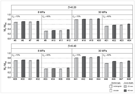
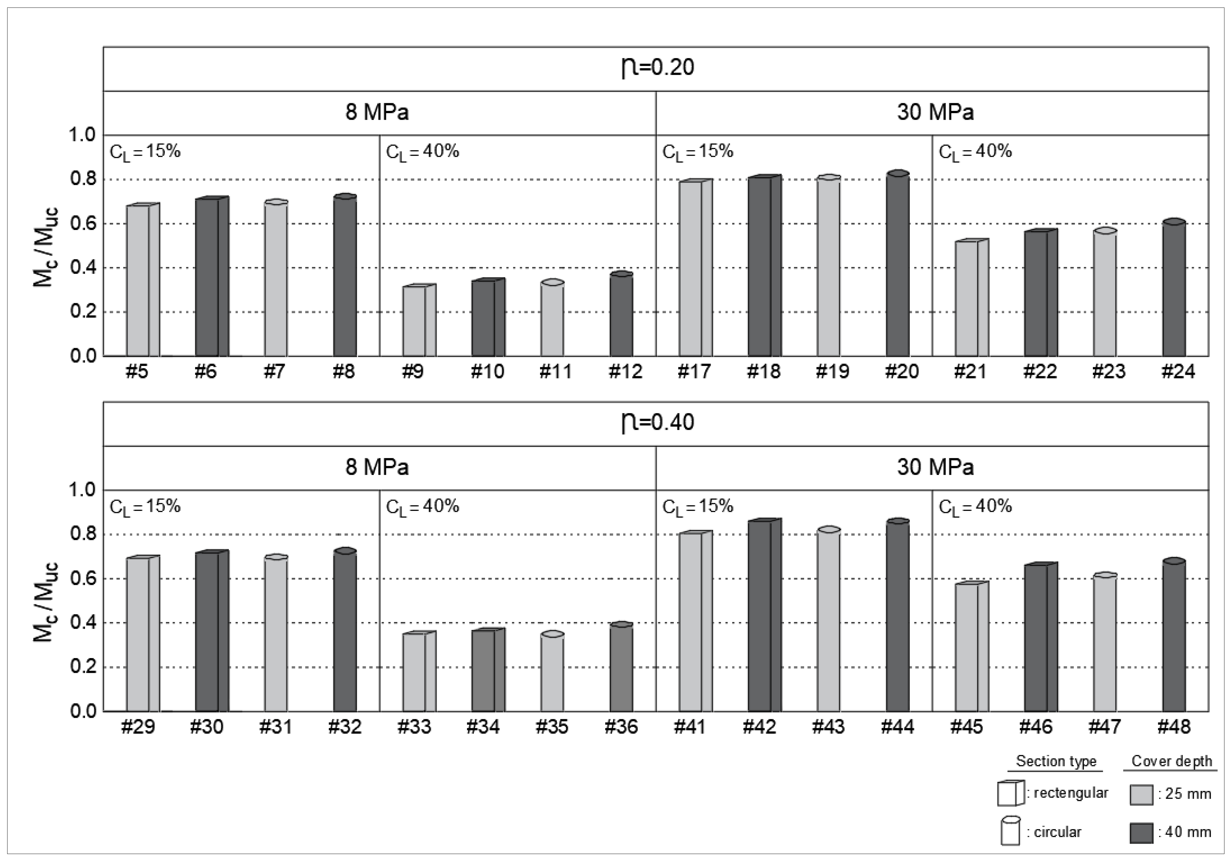
The normalized moment capacity ratios () are presented in Figure 10 to illustrate the influence of corrosion on structural performance.
Figure 10.
Normalized Mc/Muc relationships.
When the parametric study results summarized in Table 10 are examined,
- The moment capacities of all corrosion sections decreased significantly with the increase in the corrosion level.
- Similar to the experimental study, the reinforcements yield earlier due to the deteriorated mechanical properties of the reinforcement. For this reason, the displacement-based ductility values of the corroded sections were found to be higher than those of the uncorroded sections (#13 and #21).
- It was observed that the decrease in moment capacities of sections with low compressive strength (8 MPa) was higher than that of those with high compressive strength (30 MPa) (i.e., #5 and #9).
- The axial load ratio did not significantly change the calculated ratio for the corroded sections (i.e., #29 and #30).
- As the cover thickness increased, the moment and energy capacities of the sections decreased. However, in the normalized relations () and () of the sections with respect to their own reference sections, it was observed that the decrease in the specimen with 25 mm concrete cover was higher than the section with 40 mm concrete cover thickness (i.e., #5 and #6, #35 and #36).
- For all samples, the moment and energy capacities of circular sections are less than those of rectangular sections. However, the ratio of normalized () and () in circular sections was higher than in rectangular sections (#41 and #43, #45 and #47).
Although the effect of axial load ratio appeared limited within the selected range, this observation should be interpreted with caution, as the investigated ratios (20% and 40%) may not fully capture the sensitivity reported in the literature. Furthermore, the superior performance of rectangular sections compared to circular ones may be attributed to differences in reinforcement layout and confinement effectiveness under bending, particularly when corrosion-induced degradation is considered. It should also be emphasized that the selected parameter ranges are not intended to directly replicate the experimental conditions, but rather to represent a broader spectrum of possible structural states, including both typical and extreme scenarios. In particular, higher corrosion levels (e.g., 40%) are considered to explore potential upper-bound behavior, and the results under such conditions should be interpreted with caution as indicative trends rather than precise predictive values. The validity of the adopted degradation models under extreme corrosion conditions is acknowledged as a limitation, and further experimental validation in this range is recommended for future studies.
7. Conclusions
This study presents a section-based analytical framework for evaluating the structural behavior of corroded reinforced concrete columns under displacement-controlled cyclic loading. The key findings derived from the experimental, analytical, and parametric investigations are summarized as follows:
- The proposed framework successfully captures the structural response of corroded RC columns under both flexural and axial loading conditions.
- Due to the deteriorated mechanical properties of corroded specimens, the displacement-based ductility values in the experimental study and the curvature-based ductility values in the analytical study do not fully reflect the actual behavior. This non-monotonic behavior can be attributed to the combined effects of non-uniform corrosion distribution, reduction in stirrup confinement, and progressive cracking and bond deterioration. Therefore, energy-based methods provide a more reliable basis for evaluating the ductility of corroded specimens.
- Corrosion-induced degradation leads to earlier yielding and reduced elastic response, resulting in increased dominance of plastic deformation.
- The concentration of inelastic behavior occurs earlier in corroded columns, and the extent of plastic hinge regions increases with corrosion level.
- The parametric study suggests that, within the investigated parameter ranges, circular sections with larger concrete cover tend to exhibit comparatively lower reductions in normalized performance indicators than rectangular sections under similar conditions. It should be noted that this observation is based on a limited set of configurations and reflects general trends rather than statistically validated or universally applicable conclusions.
It should be emphasized that this study does not aim to propose new material constitutive models; instead, it demonstrates that the integration of experimentally validated degradation mechanisms into a unified analytical framework can effectively capture the nonlinear behavior of corrosion-damaged RC columns. Therefore, the proposed framework offers a practical contribution by enabling the direct use of sectional analysis outputs in performance-based seismic assessment of corrosion-damaged RC columns.
While the adopted modeling approach is based on generalized (average) corrosion assumptions, it is acknowledged that localized corrosion effects, particularly pitting corrosion, may lead to more severe degradation and brittle responses, which are not explicitly captured in the present analytical framework. Nevertheless, the proposed framework provides a consistent analytical basis for performance-based evaluation of corroded RC members. Future research is encouraged to incorporate experimentally calibrated models that explicitly account for localized corrosion effects and to extend the present approach to full-scale structural systems and more complex loading conditions.
Finally, it should be noted that the present study focuses on corrosion-induced degradation under seismic loading conditions. However, in real structures, deterioration mechanisms may interact with other extreme conditions, such as elevated temperatures or fire exposure. Recent studies [44] have shown that high temperatures can significantly influence the mechanical properties and structural response of reinforced concrete elements, particularly when combined with pre-existing damage mechanisms.
Therefore, extending the proposed analytical framework to account for multi-hazard scenarios, including the combined effects of corrosion and fire, represents an important direction for future research. It should also be emphasized that the proposed analytical framework is based on generalized corrosion assumptions and does not explicitly account for highly non-uniform corrosion effects, such as localized pitting. In addition, the differences between accelerated corrosion conditions used in experimental studies and natural corrosion processes in real structures may lead to variations in structural response. Therefore, the findings of this study should be interpreted within the defined scope, and further research is needed to extend the applicability of the approach to more complex and realistic corrosion scenarios.
Author Contributions
Conceptualization, A.Ç., A.İ.T., H.Y. and A.K.; methodology, A.Ç. and A.İ.T.; software, H.Y. and A.K.; validation, A.Ç., A.İ.T., H.Y. and A.K.; formal analysis, H.Y. and A.K.; investigation, A.Ç., A.İ.T. and A.K.; resources, H.Y. and A.K.; data curation, A.Ç. and A.İ.T.; writing—original draft preparation, A.Ç., A.İ.T. and A.K.; writing—review and editing, A.İ.T., H.Y. and A.K.; visualization, A.Ç., A.İ.T. and A.K.; supervision, H.Y. and A.K.; project administration, A.Ç., A.İ.T., H.Y. and A.K.; funding acquisition, H.Y. and A.K. All authors have read and agreed to the published version of the manuscript.
Funding
This research was funded by the Erzincan Binali Yıldırım University, Scientific Research Projects Co-ordination Unit (BAP) under grant number BAP-FBA-2020-659.
Institutional Review Board Statement
Not applicable.
Informed Consent Statement
Not applicable.
Data Availability Statement
The data supporting the findings of this study are available from the corresponding author upon reasonable request. The data are not publicly available due to ongoing research activities and data confidentiality.
Acknowledgments
The authors gratefully acknowledge the financial and technical support provided by the Scientific Research Projects Coordination Unit of Erzincan Binali Yıldırım University (Project No: BAP-FBA-2020-659).
Conflicts of Interest
The authors declare no conflicts of interest. The funders had no role in the design of the study; in the collection, analyses, or interpretation of data; in the writing of the manuscript; or in the decision to publish the results.
References
- Cavaco, E.S.; Neves, L.A.; Casas, J.R. Reliability-based approach to the robustness of corroded reinforced concrete structures. Struct. Concr. 2017, 18, 316–325. [Google Scholar] [CrossRef] [Scilit]
- Biczok, I. Concrete Corrosion and Concrete Protection; Chemical Publishing: New York, NY, USA, 1967; pp. 368–393. [Google Scholar]
- Alonso, C.; Andrade, C.; Rodriguez, J.; Diez, J.M. Factors controlling cracking of concrete affected by reinforcement corrosion. Mater. Struct. 1998, 31, 435–441. [Google Scholar] [CrossRef] [Scilit]
- Hansson, C.M.; Poursaee, A.; Jaffer, S.J. Corrosion of reinforcing bars in concrete. RD Ser. 2007, 3013. [Google Scholar]
- Zhang, W.; Song, X.; Gu, X.; Li, S. Tensile and fatigue behavior of corroded rebars. Constr. Build. Mater. 2012, 34, 409–417. [Google Scholar] [CrossRef] [Scilit]
- Fernandez, I.; Bairán, J.M.; Marí, A.R. Corrosion effects on the mechanical properties of reinforcing steel bars. Fatigue and σ–ε behavior. Constr. Build. Mater. 2015, 101, 772–783. [Google Scholar] [CrossRef] [Scilit]
- Ou, Y.-C.; Susanto, Y.T.T.; Roh, H. Tensile behavior of naturally and artificially corroded steel bars. Constr. Build. Mater. 2016, 103, 93–104. [Google Scholar] [CrossRef] [Scilit]
- Imperatore, S.; Rinaldi, Z.; Drago, C. Degradation relationships for the mechanical properties of corroded steel rebars. Constr. Build. Mater. 2017, 148, 219–230. [Google Scholar] [CrossRef] [Scilit]
- Yalciner, H.; Kumbasaroglu, A. Experimental Evaluation and Modeling of Corroded Reinforced Concrete Columns. ACI Struct. J. 2020, 117, 61–76. [Google Scholar] [CrossRef] [Scilit]
- Yalciner, H.; Kumbasaroglu, A. Experimental Study to Predict Bond-Slip Behavior of Corroded Reinforced Concrete Columns. ACI Struct. J. 2022, 119, 111–128. [Google Scholar] [CrossRef] [Scilit]
- Ersoy, U. Determination of moment capacities of reinforced concrete beams and columns. Tech. J. 1998, 9, 1781–1797. (In Turkish) [Google Scholar]
- Jadid, M.N.; Fairbairn, D.R. Neural-network applications in predicting moment-curvature parameters from experimental data. Eng. Appl. Artif. Intell. 1996, 9, 309–319. [Google Scholar] [CrossRef] [Scilit]
- Bedirhanoglu, I.; Ilki, A. Theoretical moment-curvature relationships for reinforced concrete members and comparison with experimental data. In Sixth International Congress on Advances in Civil Engineering; Springer: Singapore, 2004; Volume 6. [Google Scholar]
- Sheikh, M.; Tsang, H.; McCarthy, T.; Lam, N. Yield curvature for seismic design of circular reinforced concrete columns. Mag. Concr. Res. 2010, 62, 741–748. [Google Scholar] [CrossRef] [Scilit]
- Campione, G.; Cannella, F. Engineering failure analysis of corroded RC beams in flexure and shear. Eng. Fail. Anal. 2018, 86, 100–114. [Google Scholar] [CrossRef] [Scilit]
- Yüksel, S.B.; Foroughi, S. Analysis of Bending Moment-Curvature and the Damage Limits of Reinforced Concrete Circular Columns. Eur. J. Sci. Technol. 2020, 891–903. [Google Scholar] [CrossRef] [Scilit]
- Sobhani, D.; Zarei, S.; Savoj, H.; Shayanfar, M. Investigation on corrosion effects of reinforcement on the moment-curvature diagram of reinforced concrete sections. Int. J. Archit. Urban. Civ. Eng. (IJAUCE) 2018, 1, 11–22. [Google Scholar]
- Zucca, M.; Stochino, F.; Vecchi, E.; Crespi, P. On the seismic performance of existing RC motorway viaducts subject to corrosion effects. In Fib Conference on Capacity Assessment of Corroded Reinforced Concrete Structures: From Research to Daily Engineering Evaluation, CACRCS, Fib Symposium; International Federation for Structural Concrete Fédération Internationale du Béton: Lausanne, Switzerland, 2025; pp. 282–289. [Google Scholar]
- François, R.; Castel, A.; Vidal, T. A finite macro-element for corroded reinforced concrete. Mater. Struct. 2006, 39, 571–584. [Google Scholar] [CrossRef] [Scilit]
- Almassri, B.; Al Mahmoud, F.; Francois, R. Behaviour of corroded reinforced concrete beams repaired with NSM CFRP rods, experimental and finite element study. Compos. Part B Eng. 2016, 92, 477–488. [Google Scholar] [CrossRef] [Scilit]
- Jnaid, F.; Aboutaha, R.S. Residual flexural strength of corroded reinforced concrete beams. Eng. Struct. 2016, 119, 198–216. [Google Scholar] [CrossRef] [Scilit]
- Vu, N.S.; Yu, B.; Li, B. Prediction of strength and drift capacity of corroded reinforced concrete columns. Constr. Build. Mater. 2016, 115, 304–318. [Google Scholar] [CrossRef] [Scilit]
- Zaghian, S.; Martín-Pérez, B.; Almansour, H. Nonlinear finite element modeling of the impact of reinforcement corrosion on bridge piers under concentric loads. Struct. Concr. 2022, 23, 138–153. [Google Scholar] [CrossRef] [Scilit]
- Celik, A.; Yalciner, H.; Kumbasaroglu, A.; Turan, A.I. An experimental study on seismic performance levels of highly corroded reinforced concrete columns. Struct. Concr. 2022, 23, 32–50. [Google Scholar] [CrossRef] [Scilit]
- Chadwell, C. XTRACT v.3.0., Cross-Sectional X Structural Analysis of Components; Imbsen Software Systems: Sacramento, CA, USA, 2004. [Google Scholar]
- TS500; Design and Construction Rules for Reinforced Concrete Structures. Turkish Standards Institution (TSE): Ankara, Turkey, 2000. (In Turkish)
- A370; ASTM (American Standards for Testing and Materials), Standard Test Methods and Definitions for Mechanical Testing of Steel Products. ASTM International: West Conshohocken, PA, USA, 2008; pp. 1–47.
- Yuan, Y.; Ji, Y.; Shah, S.P. Comparison of two accelerated corrosion techniques for concrete structures. ACI Struct. J. 2007, 104, 344–347. [Google Scholar] [CrossRef] [Scilit] [PubMed]
- Li, Q.; Jin, X.; Yan, D.; Fu, C.; Xu, J. Study of wiring method on accelerated corrosion of steel bars in concrete. Constr. Build. Mater. 2021, 269, 121286. [Google Scholar] [CrossRef] [Scilit]
- FEMA-461; FEMA (Federal Emergency Management Agency), Interim Testing Protocols for Determining the Seismic Performance Characteristics of Structural and Nonstructural Components. Federal Emergency Management Agency: Washington, DC, USA, 2007; pp. 1–113.
- Sezen, H.; Moehle, J.P. Shear strength model for lightly reinforced concrete columns. J. Struct. Eng. 2004, 130, 1692–1703. [Google Scholar] [CrossRef] [Scilit]
- Turkish Building Earthquake Code (TBEC). Specifications for Buildings to Be Built in Seismic Zones; Republic of Turkey Ministry of Environment and Urbanization: Ankara, Turkey, 2018. (In Turkish) [Google Scholar]
- Mander, J.B.; Priestley, M.J.N.; Park, R. Observed Stress-Strain Behavior of Confined Concrete. J. Struct. Eng. 1988, 114, 1827–1849. [Google Scholar] [CrossRef] [Scilit]
- Kent Dudley, C.; Park, R. Flexural members with confined concrete. J. Struct. Div. 1971, 97, 1969–1990. [Google Scholar] [CrossRef] [Scilit]
- Turan, A.I.; Ayaz, Y.; Yalçıner, H.; Kumbasaroğlu, A.; Çelik, A. Experimental and Analytical Investigation of Moment-Carrying Capacities of Reinforced Concrete Frame Systems Corroded by Accelerated Corrosion Method. J. Inst. Sci. Technol. 2024, 14, 755–772. [Google Scholar] [CrossRef] [Scilit]
- Vecchio, F.J.; Collins, M.P. The modified compression-field theory for reinforced concrete elements subjected to shear. ACI J. 1986, 83, 219–231. [Google Scholar]
- Cape, M. Residual Service-Life Assessment of Existing R/C Structures. Master’s Thesis, Chalmers University of Technology and Milan University of Technology, 1999. [Google Scholar]
- Frankel, G.S. Pitting corrosion of metals: A review of the critical factors. J. Electrochem. Soc. 1998, 145, 2186–2198. [Google Scholar] [CrossRef] [Scilit]
- Yalciner, H.; Eren, O.; Sensoy, S. An experimental study on the bond strength between reinforcement bars and concrete as a function of concrete cover, strength and corrosion level. Cem. Concr. Res. 2012, 42, 643–655. [Google Scholar] [CrossRef] [Scilit]
- Paul, S.C.; Babafemi, A.J.; Conradie, K.; van Zijl, G.P. Applied voltage on corrosion mass loss and cracking behavior of steel-reinforced SHCC and mortar specimens. J. Mater. Civ. Eng. 2017, 29, 04016272. [Google Scholar] [CrossRef] [Scilit]
- Crespi, P.; Zucca, M.; Valente, M.; Longarini, N. Influence of corrosion effects on the seismic capacity of existing RC bridges. Eng. Fail. Anal. 2022, 140, 106546. [Google Scholar] [CrossRef] [Scilit]
- Wang, X.-H.; Liu, X.-L. Modeling the flexural carrying capacity of corroded RC beam. J. Shanghai Jiaotong Univ. (Sci.) 2008, 13, 129–135. [Google Scholar] [CrossRef] [Scilit]
- Wu, Q.; Yuan, Y.S. Experimental study on the deterioration of mechanical properties of corroded steel bars. China Civ. Eng. J. 2008, 41, 42–47. [Google Scholar]
- Bolina, F.L.; Fachinelli, E.G.; Rodrigues, J.P.C. Analysis of building structures subjected to electric vehicle fires. J. Build. Eng. 2025, 107, 112769. [Google Scholar] [CrossRef] [Scilit]

Disclaimer/Publisher’s Note: The statements, opinions and data contained in all publications are solely those of the individual author(s) and contributor(s) and not of MDPI and/or the editor(s). MDPI and/or the editor(s) disclaim responsibility for any injury to people or property resulting from any ideas, methods, instructions or products referred to in the content. |
© 2026 by the authors. Licensee MDPI, Basel, Switzerland. This article is an open access article distributed under the terms and conditions of the Creative Commons Attribution (CC BY) license.