


Abstract
To address the technical challenge of large-area roof hanging and induced strong strata behaviors in deep mines with hard roof strata, a study on pressure relief using hydraulic fracturing technology was conducted, taking the 1012006 working face in the Yuanzigou Coal Mine as the engineering background. Through geological survey and key stratum theory analysis, a low-position key stratum located 23 m above the roadway roof was identified as the target layer for fracturing. True triaxial hydraulic fracturing experiments coupled with acoustic emission (AE) monitoring revealed a synchronous response characterized by a sudden drop in injection pressure and a rapid increase in AE counts. This established a quantitative correlation between rock mass fracturing and AE characteristics, providing a theoretical basis for field microseismic monitoring. Based on the “dual-borehole synergy” borehole layout principle, a fracturing network comprising 6 drilling fields and 12 directional long boreholes was designed, with a total drilling length of 5727 m and 120 planned fracturing stages. Specialized equipment was selected for implementation. Field monitoring results demonstrated: a maximum fracturing influence radius of 27.8 m; that the average daily frequency and total energy of microseismic events decreased by 50.65% and 27.73%, respectively; and that the stress in the deep part of the roadway decreased by 17.69%. These results confirm the effective improvement of the roof stress environment and the successful achievement of the expected pressure relief and rockburst prevention effect.
1. Introduction
China’s energy resource endowment of ‘rich coal, poor oil, less gas’ determines the fundamental role of coal in national economic and social development. However, with the depletion of shallow resources and the increasing depth and intensity of coal mining, the problem of deep hard roof control faced by many coal mines has become increasingly prominent [1,2,3,4,5]. This type of roof possesses high strength and strong integrity. It is not prone to timely collapse after mining, easily forming a large-scale suspended roof on the goaf side, leading to sharp stress concentrations around the stope and accumulation of significant elastic energy [6,7,8]. When the energy accumulates to a critical state, it may induce dynamic disasters such as manifestation of intense mine pressure or even rockbursts, seriously threatening mine production safety and personnel’s lives. It is a major technical challenge that must be overcome to achieve safe and efficient mining in coal mines [9,10,11,12].
In the development process of hard roof control technology in coal mines, blasting for pressure relief has been widely used as an effective technical means. This method involves conducting blasting operations in the roof strata and using explosion energy to instantaneously destroy the integrity of the rock mass structure, thereby weakening the hard roof and reducing stress concentration. However, with increasing mining depth and increasingly complex geological conditions, the limitations of traditional blasting pressure relief technology have become more prominent: the strong impact disturbance generated during construction can easily cause secondary damage to the roadway surrounding rocks; the range and effect of pressure relief are difficult to control accurately, and there is a risk of inducing larger-scale dynamic disasters in deep high-stress environments [13,14,15]. These technical bottlenecks have prompted researchers to seek safer and more controllable pressure relief methods. In this context, hydraulic fracturing technology has been gradually introduced into the field of hard roof control in coal mines due to its unique advantages. This technology originates from oil and gas field development projects. Its basic principle is to achieve controllable weakening of the rock mass structure by injecting high-pressure fluid into the target rock layer and forming an extended fracture network within the rock mass. Compared to traditional blasting technology, hydraulic fracturing is characterized by low disturbance, controllable action range, and uniform energy release. It can effectively reduce the strength of the roof rock mass, promote the transfer of the stress concentration zone deeper, and significantly shorten the periodic weighting interval of the working face [16,17,18,19,20,21]. These technical characteristics make it particularly suitable for pressure relief treatment of hard roofs in deep mines and provide a new technical approach for safe and efficient coal mining.
While the challenge of hard roof control is widely recognized, the existing literature lacks an in-depth discussion on the synergistic effects of the dual-hole fracturing mode. Addressing this gap, this study utilizes the 1012006 working face of Yuanzigou Coal Mine as an engineering background to systematically investigate the full spectrum of hydraulic fracturing, ranging from geological analysis and mechanism experiments to engineering design and evaluation. Distinguishing itself from traditional methods, this research elucidates the specific interaction mechanisms between adjacent fracture networks under a dual-hole collaborative arrangement, with a particular focus on quantifying the ‘synergistic effect’ and its impact on energy release. The primary contribution of this work is the development of a set of refined optimization parameters designed to maximize this synergy, thereby establishing a comprehensive technical system for hard roof pressure relief. Ultimately, this study provides a novel solution for improving roof crushing efficiency in complex hard strata, offering a theoretical basis and practical reference for safe mining under similar conditions.
2. Analysis of Engineering Geological Conditions
2.1. Basic Geological Conditions
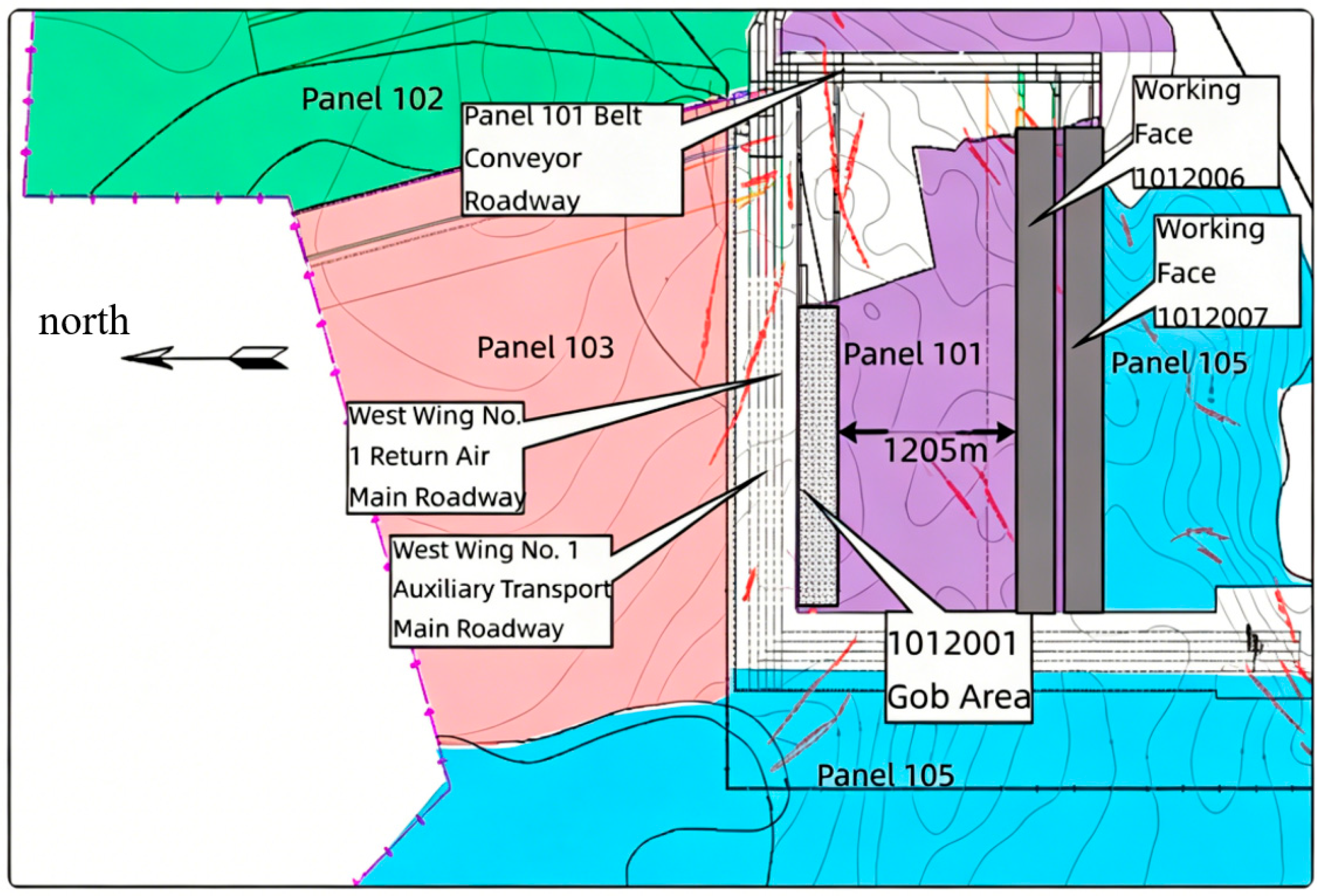
This study takes the 1012006 fully mechanized top coal caving face of Yuanzigou Coal Mine in Linyou County, Shaanxi Province, as the engineering background. The burial depth of the working face ranges from 616 to 715 m, mining the No. 2 coal seam. The average thickness of the coal seam is 11.56 m, which belongs to a thick coal seam. The designed length of the conveyor belt roadway is 2658 m, the designed length of the return airway is 2761 m, the inclined length of the working face is 240 m, and the designed mining length is 2123 m. The location of the working face and the surrounding mining conditions are shown in Figure 1.
Figure 1.
Location and Surrounding Mining Conditions of Working Face 1012006.
The overlying strata structure is complex, characterized by the occurrence of multiple thick and hard sandstone layers above the coal seam. According to the analysis of the histogram of borehole K14-5 in the middle of the working face, the key thick and hard rock strata are mainly distributed in three intervals: a 20 m thick fine-grained sandstone occurs 119.47 m above the coal seam; at 268.54 m above, there is a set of continuous sandstone and conglomerate interbeds with a total thickness exceeding 200 m; at 620.44 m above, there is a 30 m thick siltstone. It is particularly important to note that within the range of 18.32–83.38 m from the coal seam roof, there are generally fine sandstone layers with thicknesses of 2.0–10.0 m, and within the range of 19.68–64.93 m, there are multi-layered sandstone layers with a total thickness of 16.42–69.88 m. These rock layers constitute the immediate roof and main roof of the working face.
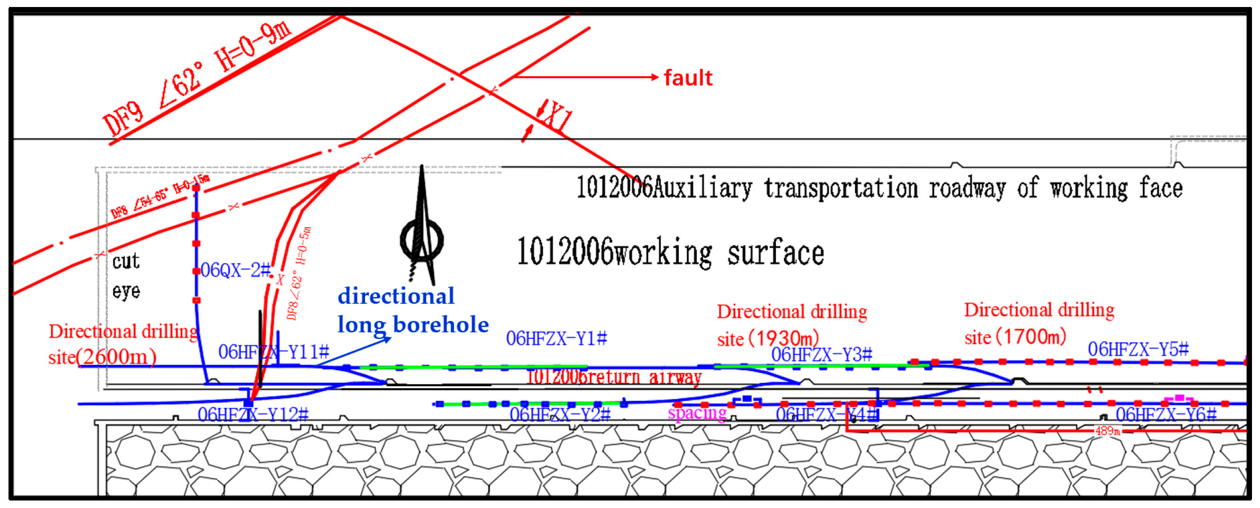
Regarding geological structures, a series of faults such as DF8 and DF9 (throw H = 0–10 m) and multiple fold structures such as X1 and B2 have developed within and around the working face. The existence of these structures provides conditions for regional geological stress concentration. The geological structure of the working face is shown in Figure 2.
Figure 2.
Geological Structures of Working Face 1012006.
2.2. The Key Problems: Hard Roof Hanging and Rockburst Risk
Because the 1012006 working face employs the gob-side entry driving method, the return airway is adjacent to the goaf of the 1012007 working face, with a 35 m wide section coal pillar left between them. Early geological exploration and evaluation indicated that the working face was judged to have a medium rockburst risk during excavation. The root causes of its risk mainly stem from the following aspects:
Deep Mining Depth and Strong Mining-Induced Stress: A burial depth exceeding 600 m leads to high in situ stress. Coupled with mining disturbance from the working face, it makes the coal–rock mass prone to accumulating enormous elastic energy.
Hard Roof Hanging Structure: The overlying thick and hard sandstone layers have high strength and good integrity, making it difficult for them to collapse promptly after working face extraction, easily forming a large-scale “cantilever beam” structure on the goaf side. Exploration confirmed that above the coal pillar between the 1012006 return airway and the adjacent goaf, a 10–19 m hanging roof still exists, constituting a theoretical “F-shaped” spatial structure.
Superimposed Tectonic Stress: Residual tectonic stresses exist in areas of geological structures such as the B2 anticline and DF8 fault, which superimpose mining-induced stresses, further exacerbating the degree of stress concentration.
The coupling effect of the above factors means the working face faces serious threats from strong strata pressure behaviors induced by large-scale fracturing of the hard roof and even rockbursts during the mining process. Therefore, proactive pressure relief treatment of the hard roof (key stratum) is the primary technical challenge to ensure the safe and efficient mining of the working face.
2.3. Key Stratum Analysis and Determination of Fracturing Target Layer
Based on the key stratum theory, assuming a certain rock layer is the first key stratum, its control range over the overlying strata can reach the nth layer. If the (n + 1)th layer is the second key stratum, its load relationship must satisfy the following:
where q~n + 1~, q~n~ are the loads borne by the first key stratum calculated up to the (n + 1)th and nth layers, respectively.
Assuming the load imposed on the first key stratum by the nth rock layer is (qn)1~, its calculation method is as follows:
where En is the elastic modulus of each rock layer; hn is the thickness of each rock layer; and γn is the unit weight of each rock layer.
Simultaneously, the breaking distance of the lower hard rock layer is less than that of the upper hard rock layer, i.e.:
where lj is the breaking distance of the j layer.
Based on Equations (1)–(3), the roof strata structure of the working face was analyzed and calculated to determine the key strata, playing a major controlling role in the overlying roof strata. To precisely locate the underground fracturing layer, two underground geological coring boreholes were constructed at 1930 m and 2230 m in the 1012006 return airway. Borehole detection results showed that the vertical distances from the target key stratum (theoretically calculated as Key Stratum 2) to the roadway roof were 18.8 m and 22.9 m, respectively.
Comprehensive analysis of the geological borehole histogram and underground exploration data indicates the existence of three continuous thick and hard sandstone layers within 100 m above the working face roof. Their lithology is hard, making them the main cause for maintaining roof stability and causing the hanging roof problem. To address the hanging roof near the coal seam while considering high-level pressure relief, it was ultimately decided to set the target layer for underground fracturing as this low-position key stratum, as shown in Table 1. The aim is to use hydraulic fracturing technology to cut off the lateral hanging roof on the goaf side, modify the roof rock mass structure, and achieve large-scale, advanced, uniform pressure relief.
Table 1.
Geological Core Drilling and Target Strata for Fracturing.
3. Experimental Study on Hydraulic Fracturing Mechanism and Acoustic Emission Response Characteristics
3.1. Experimental Objective
Based on the aforementioned engineering geological conditions, the core threat of strong strata pressure in the working face lies in the elastic energy accumulated in the hard roof. Hydraulic fracturing technology aims to release this energy in a controlled manner by pre-fracturing the roof. To deeply reveal the intrinsic mechanism of fracturing-induced rock mass failure and provide theoretical and parametric foundations for field microseismic monitoring, this study conducted physical simulation experiments of true triaxial hydraulic fracturing coupled with acoustic emission (AE) monitoring in the laboratory. Acoustic emission and mine microseismicity share the same physical nature, differing only in scale. Therefore, accurately capturing the AE response patterns during the fracturing process in the laboratory can provide direct guidance for interpreting field microseismic monitoring data.
3.2. Experimental System and Scheme
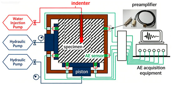
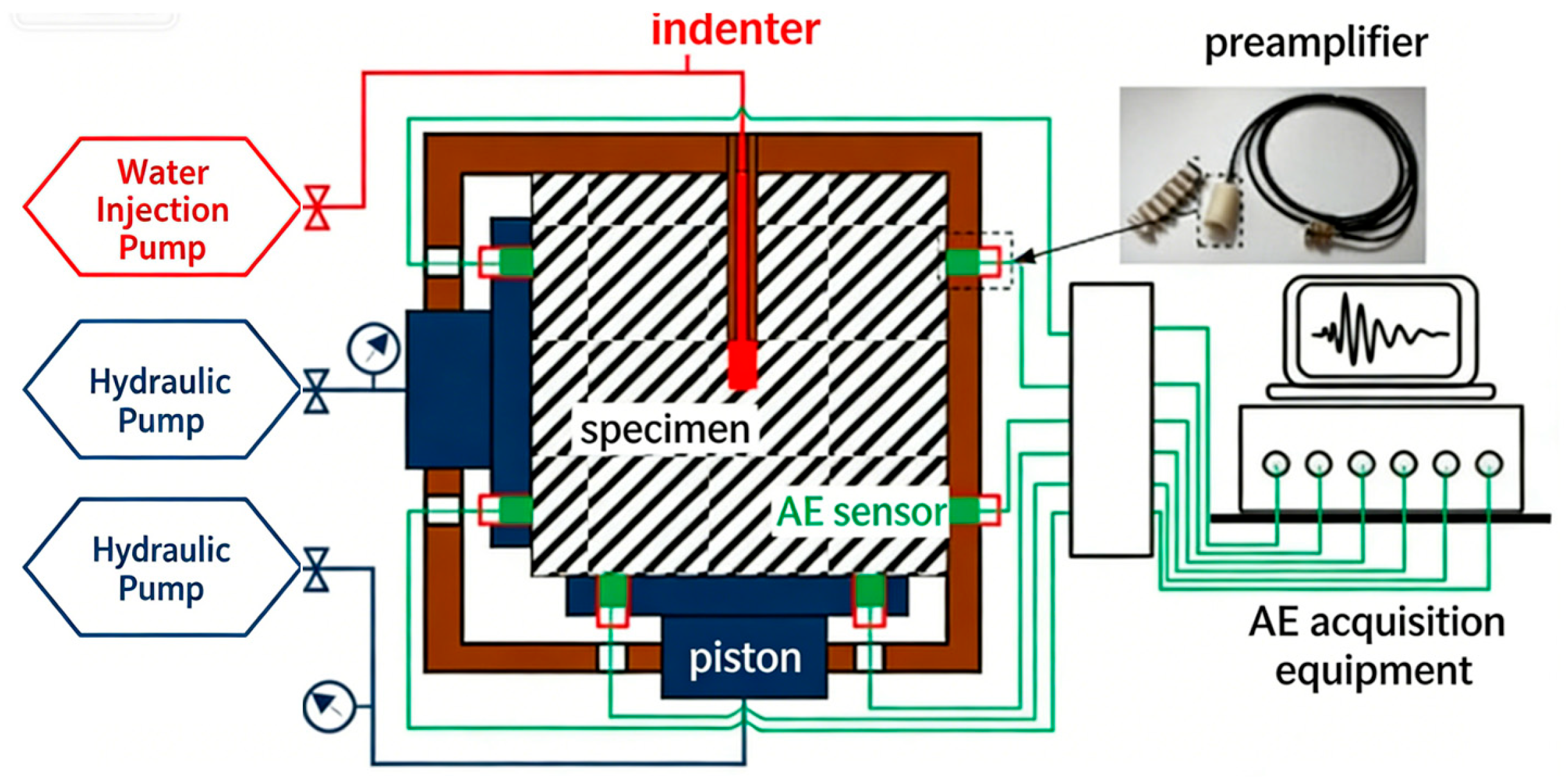
To realistically replicate the underground rock strata stress environment, the experiment employed a self-built true triaxial hydraulic fracturing AE testing system, as shown in Figure 3. The core of this system consists of three parts: a true triaxial stress loading subsystem capable of independently applying stresses up to 70 MPa in three orthogonal directions; a DS5 full-information acoustic emission analysis subsystem for collecting and locating AE signals throughout the process; and a constant-flow water injection subsystem that injects fracturing fluid at a rate of 100 mL/min.
Figure 3.
True Triaxial Hydraulic Fracturing AE Testing System.
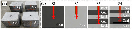
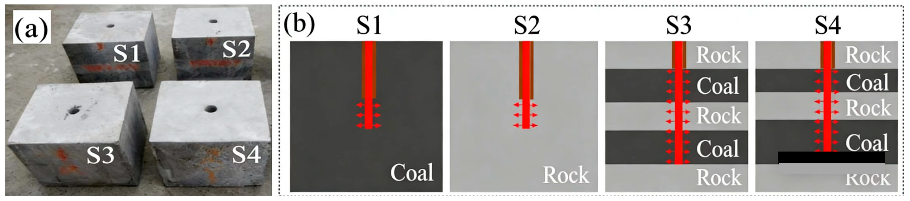
Four specimens were numbered S1, S2, S3, and S4, each with dimensions of 300 mm × 300 mm × 300 mm. S1 simulated single coal seam fracturing, S2 simulated single rock layer fracturing, and S3 and S4 simulated multi-seam fracturing. The specimens are shown in Figure 4.
Figure 4.
Specimen Preparation. (a) Finished test sample. (b) The schematic diagram of coal rock structure of test sample.
The specimens are all concrete-based, and different concrete proportions are used to simulate the mechanical properties of coal and rock. First, similar materials for simulated coal and rock were prepared according to the designed proportions and then cast or pressed into standard cubic blocks. For composite samples S3 and S4, they were assembled following the designed layer sequence: S3 is rock–coal–rock and S4 is rock–coal–rock–coal–rock, and the prefabricated coal and rock blocks were bonded together using high-strength structural adhesive. Finally, a cylindrical borehole was drilled vertically at the center of each sample. Among them, S1 is a pure coal specimen, S2 is a pure rock specimen, and S3 and S4 are layered composite coal–rock specimens.
3.3. Correlation Analysis Between Acoustic Emission Response Characteristics and Fracturing Process
(1) AE Ring-Down Count and Dynamic Crack Propagation
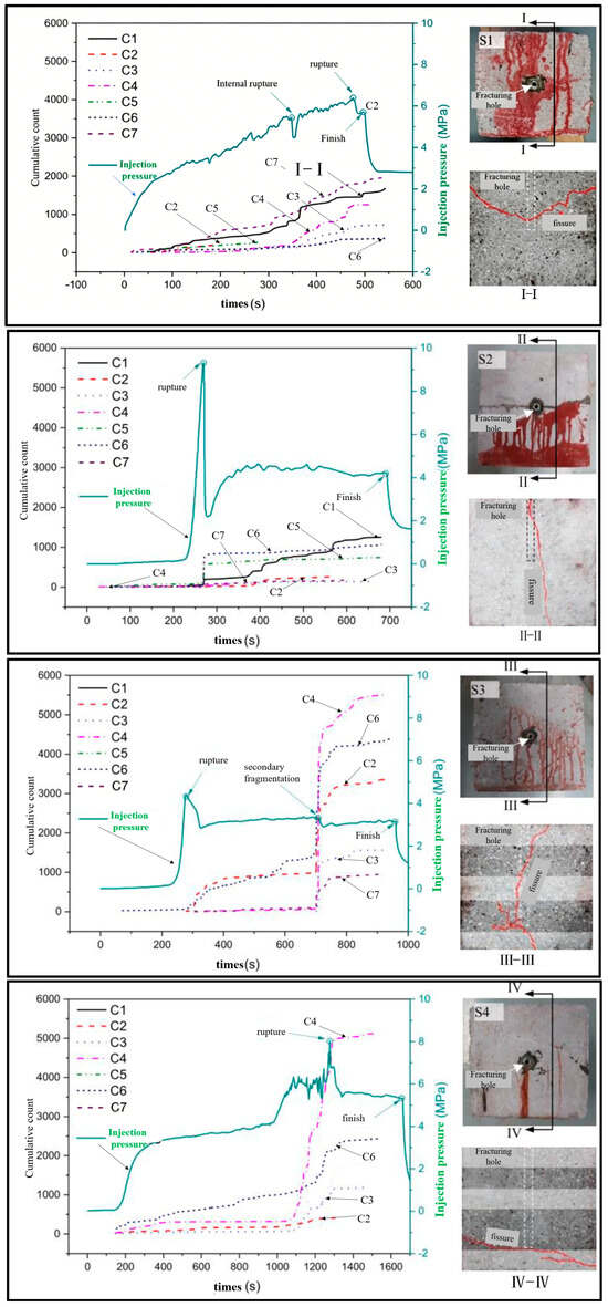
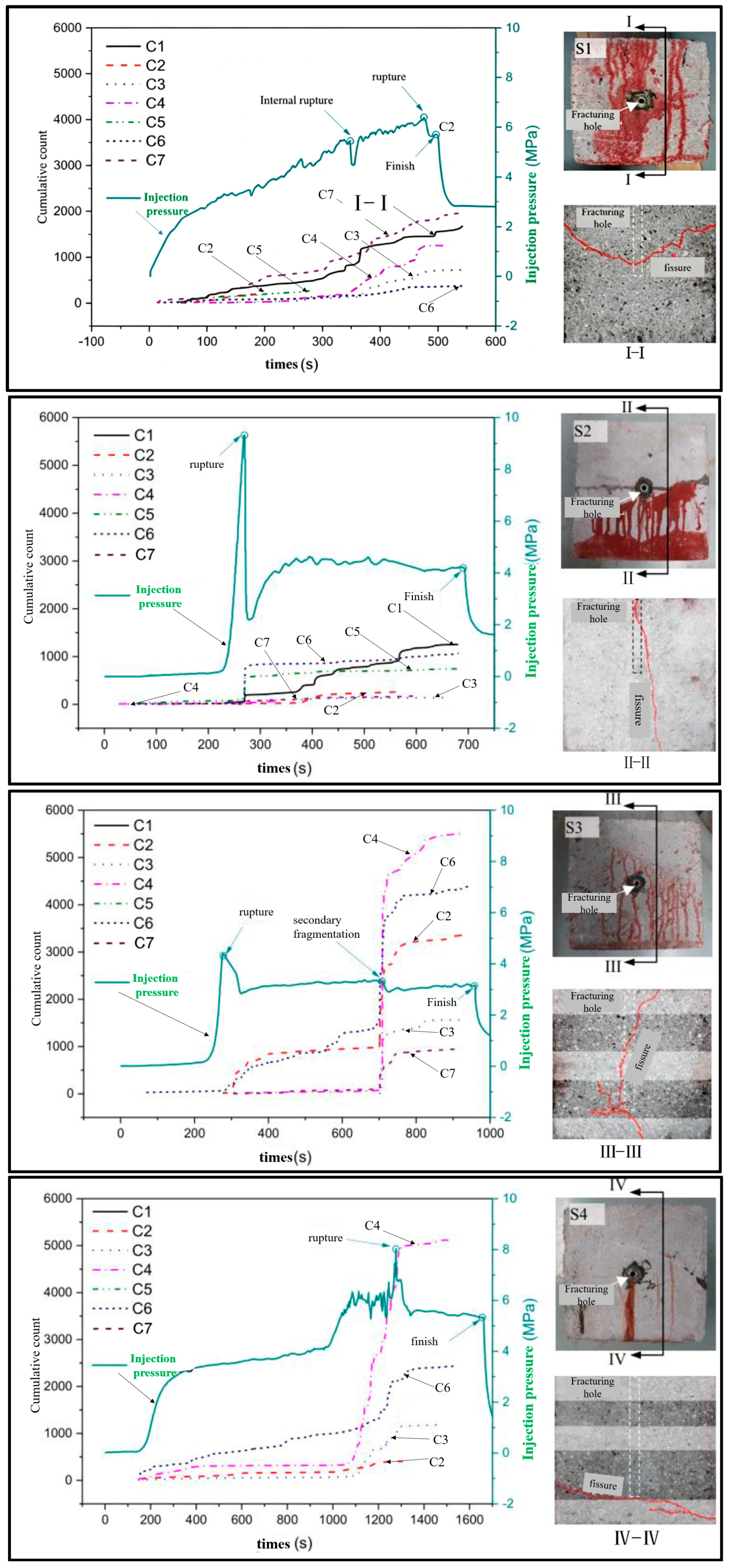
A total of eight acoustic emission (AE) sensors were arranged in this test to monitor the whole process of hydraulic fracturing of the specimens. Benefiting from the significant differences in the physical and mechanical properties between coal and rock materials, as well as the interlayer interface effects in the multi-layered coal–rock specimens (S3 and S4), the crack initiation and propagation paths during hydraulic fracturing exhibited strong heterogeneity. Meanwhile, the propagation attenuation, transmission and reflection laws of AE stress waves in coal, rock and their interfaces were distinctly different, which ultimately led to significant differences in the AE response characteristics (such as amplitude, frequency, and energy) captured by sensors at different positions. In addition, due to the signal attenuation and superposition effects in the heterogeneous coal–rock medium, some sensors collected AE signals with relatively weak amplitude or overlapping signals. Therefore, only 5–6 characteristic curves were clearly presented in the figure. This phenomenon is consistent with the actual mechanical response characteristics of heterogeneous coal–rock mass during hydraulic fracturing, verifying the reliability of the experimental results.
The experimental results are shown in Figure 5. The AE ring-down count effectively characterized the damage rate inside the rock mass. The cumulative AE count and water injection pressure curves showed significant co-evolution. Taking specimen S1 as an example, during the initial fracturing stage, the pressure rose steadily, and the AE count increased slowly, corresponding to micro-crack initiation. When a sharp pressure drop occurred (e.g., at 348 s and 475 s for S1), the AE count simultaneously surged, marking the generation or interconnection of macroscopic fractures. In specimens S2, S3, and S4 containing rock layers, the leap in AE count at the moment of rock layer fracture was particularly prominent. This indicates that a sudden drop in injection pressure accompanied by a sharp increase in AE count is a reliable acoustic precursor for judging macroscopic rock mass failure. The entire fracturing process, through AE counts, clearly showed the progressive characteristics of repeated crack initiation and propagation, rather than instantaneous completion.
Figure 5.
AE Count Characteristics During the Fracturing Process of Specimens S1–S4.
(2) AE Energy Distribution and Fracture Type Identification
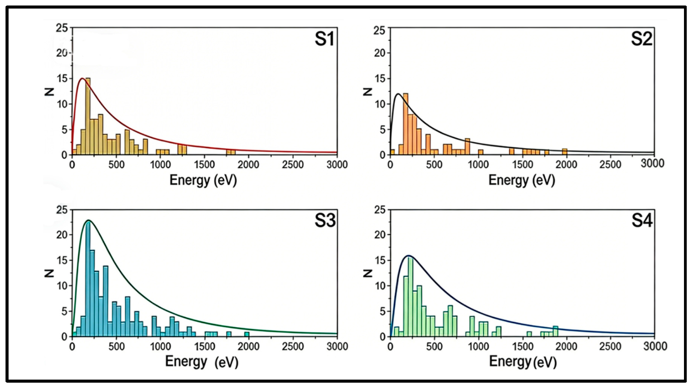
AE energy analysis provided a key criterion for identifying fracture scale and type. The experiment found that the AE energy release level of rock sample S2 was significantly higher than that of coal sample S1. In the layered specimens, the highest-energy AE events precisely corresponded to the moments of rock layer fracture. This confirms that the magnitude of AE energy can effectively distinguish the nature of the fracture source; the rupture of high-strength rock layers releases higher-energy signals.
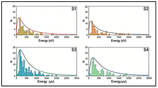
Statistical analysis of the AE energy distribution further revealed that the AE energy of all specimens followed a power-law distribution in double logarithmic coordinates, and the power-law exponent for layered specimens was smaller than that for homogeneous specimens. This indicates that layered rock masses are more unstable during the fracturing process, with a higher risk of large-scale sudden ruptures. The overall characteristics of energy distribution conformed to a log-normal distribution, as shown in Figure 6, establishing a model basis for the statistical analysis of field microseismic data.
Figure 6.
Log-Normal Distribution Characteristics of AE Energy During the Fracturing Process.
3.4. Guiding Significance of Experimental Conclusions for Field Practice
This experiment systematically established a quantitative correspondence between rock mass fracturing and acoustic emission activity during the hydraulic fracturing process, constructing a theoretical basis for evaluating the effectiveness of field microseismic monitoring. The experiment confirmed that sharp changes in the frequency of AE events (ring-down counts) directly reflect the active propagation degree of the fracture network, while high-energy AE events are reliable indicators of structural failure in key hard rock layers.
Extending this logic to the field: if during hydraulic fracturing operations, the microseismic monitoring system captures a significant increase in event frequency and energy level, it proves that the fracturing operation is effectively fracturing the target rock layer, forming a fracture network and releasing energy. Conversely, during the mining period of the working face after the fracturing project is completed, if the overall frequency and energy of microseismic events show a significant and sustained downward trend, it strongly indicates that the high stress and elastic energy originally stored in the roof rock mass have been effectively dissipated through pre-fracturing, fundamentally reducing the risk of strong strata pressure manifestation during mining.
4. Design of Roof Directional Long-Borehole Fracturing Scheme
4.1. Fracturing Scheme Design
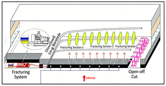
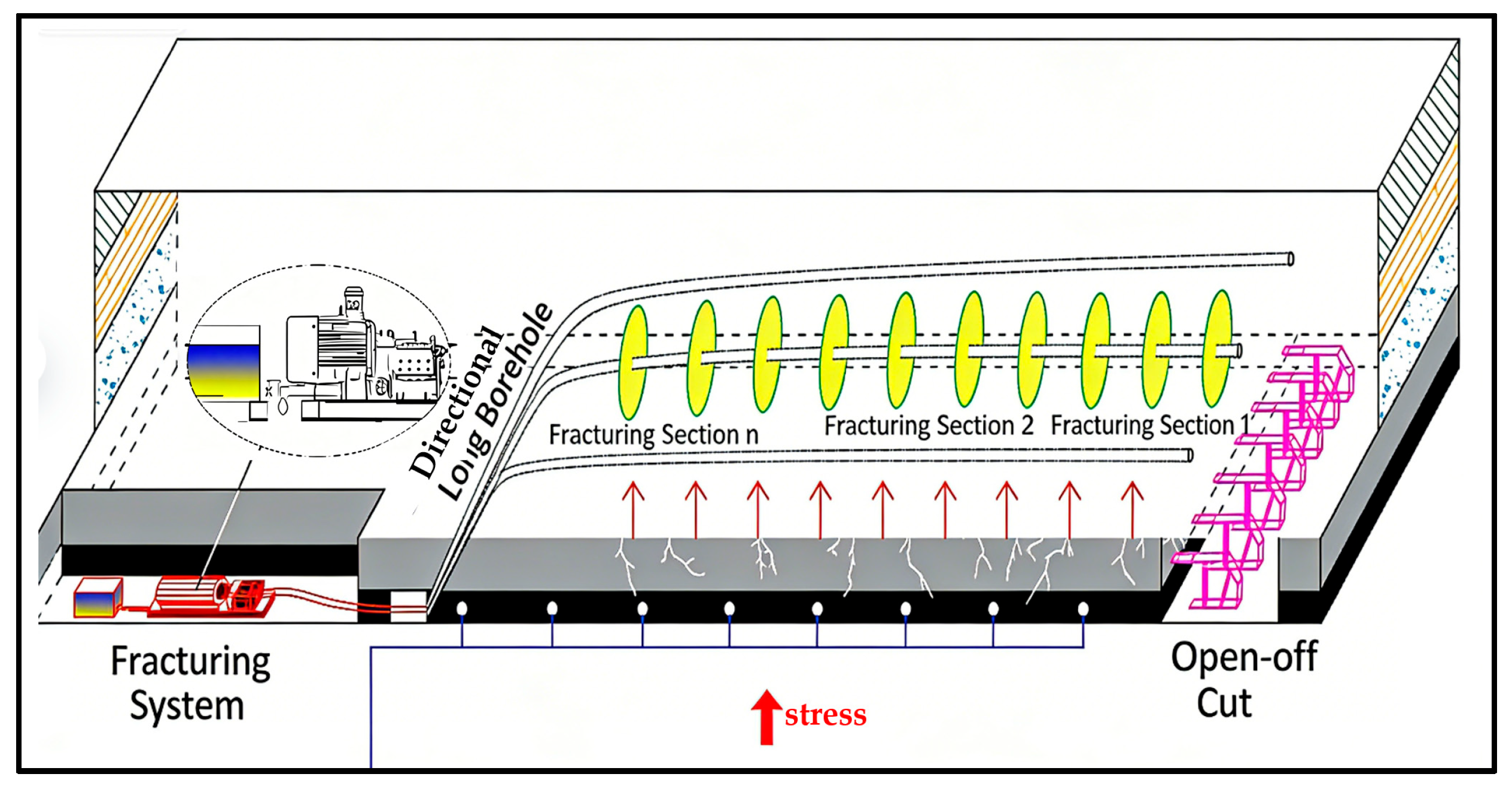
Based on preliminary engineering geological analysis and experimental research results, a directional long-borehole hydraulic fracturing pressure relief scheme targeting the low-position key stratum was formulated to address the hard roof control challenge of the 1012006 working face. This scheme aims to achieve large-scale and precise weakening of the roof rock layers by optimizing the layout of drilling fields and borehole trajectory design. The directional long-borehole fracturing technology is illustrated in Figure 7.
Figure 7.
Directional Long-Borehole Fracturing Technology.
The parameters for the hydraulic fracturing technical measures, such as water injection volume and pressure, are determined based on influencing factors including the geological environment, stress distribution, and physical–mechanical parameters of the target fracturing layer. The number of stages and injection time are determined based on experience and field test results. The fracture pressure Pk of the rock layer can be calculated according to Equation (4):
where σh is the minimum principal stress, MPa; σH is the maximum principal stress, MPa; σt is the tensile strength, MPa, taken as an average of 2; and P0 is the pore pressure, MPa, taken as 0.1.
Then, based on the pressure parameter limits for the fracturing type, the fracture pressure Pk is substituted into Equation (5) to calculate the hydraulic fracturing pump pressure Pw:
where the fracturing fluid column pressure in the pipeline PH can be calculated using Equation (6):
ρ is the density of the fracturing fluid, kg/m3; g is the acceleration due to gravity, N/kg, taken as 9.8; and h is the elevation difference in the fracturing pipeline, i.e., the final borehole elevation minus the opening elevation, m.
The frictional pressure loss along the fracturing pipeline Pr can be calculated using Equation (7):
where L is the pipeline length, m, taken as 150–650, and λ1 is the friction coefficient, MPa/m.
Based on the estimated pore volume of the fracturing influence range for the target rock layer, and considering fluid loss, the fracturing water volume Vw can be estimated using Equation (8):
where Vv is the volume of the rock mass within the fracturing influence range, m3; λ2 is the water absorption coefficient of the roof and floor strata; and λ3 is the water absorption coefficient for dense and hard rock layers.
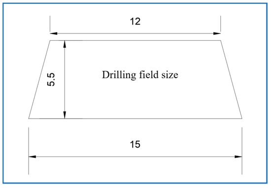
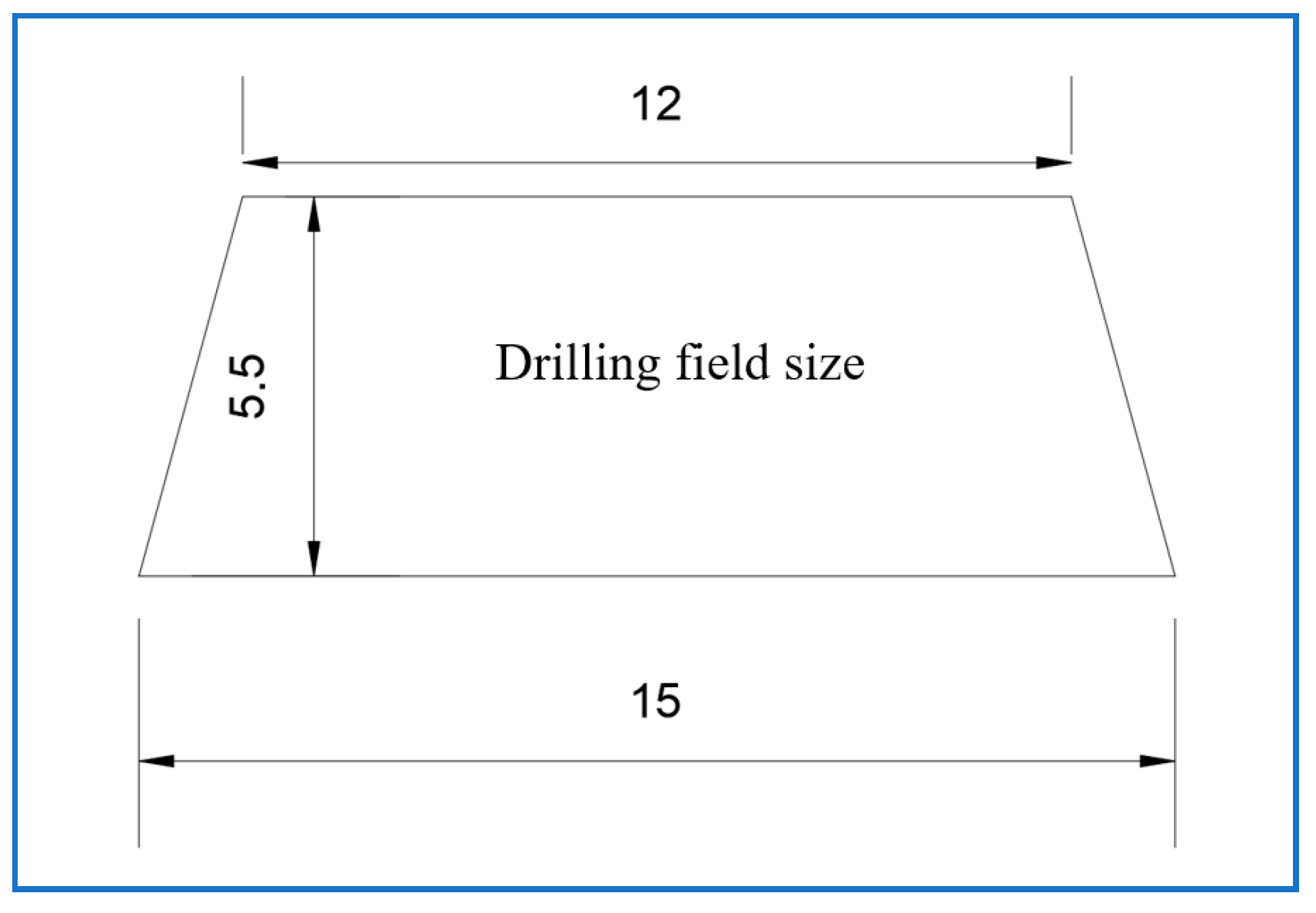
To achieve full coverage of the entire working face length, a staged layout principle was adopted along the 1012006 return airway, establishing a total of 5 drilling fields located at distances of 1000 m, 1200 m, 1700 m, 1930 m, and 2400 m from the roadway entrance, respectively. Additionally, the No. 1 chamber of the adjacent 1012007 haulage roadway was utilized as a supplementary drilling field, forming a three-dimensional fracturing network covering the full strike length of the working face. All drilling fields were expanded and brushed to a specification of 15 m × 5.5 m, as shown in Figure 8. This size design fully considered multiple requirements, including directional drill rig equipment placement, fracturing operation space, and personnel operational safety, ensuring the efficient execution of the entire fracturing construction process.
Figure 8.
Drilling field size.
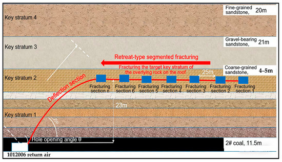
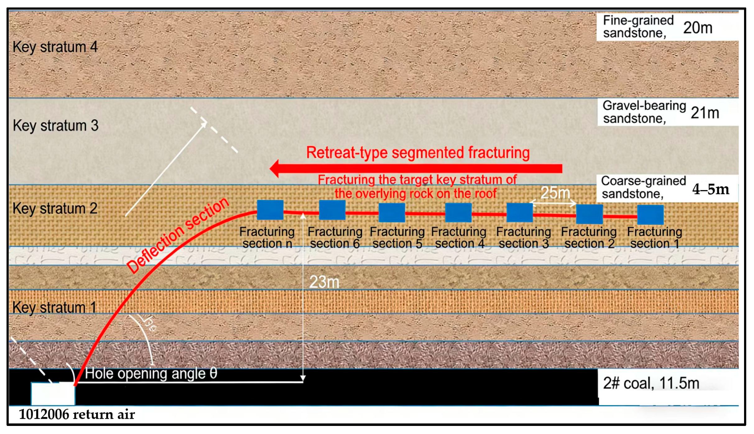
Based on underground geological drilling verification results, the target fracturing layer was determined to be the low-position key stratum (Key Stratum 2) approximately 23 m above the roadway roof, as shown in Figure 9. This layer’s lithology is mainly coarse-grained sandstone, with a stable thickness of 4.8–5.0 m. Its hard and dense lithological characteristics make it the most effective layer for achieving roof weakening. Based on this geological understanding, 12 directional long boreholes were designed and constructed, with a total footage of 5727 m, of which the total horizontal section length was 3576 m. Precise trajectory control technology ensured that all borehole horizontal sections could be accurately placed in the middle of the target key stratum, creating a prerequisite for effective fracturing.
Figure 9.
Staged Fracturing Process and Stratum Selection for Directional Long Boreholes in the Roof.
In terms of borehole trajectory design, an innovative “dual-borehole synergy” differentiated layout method was adopted. The functional division ‘pilot hole’ is responsible for geological exploration and risk prediction (such as lithology and ground stress test), providing geological basis for the main hole; the ‘main hole’ performs precise fracturing operations based on the pilot hole data. Collaborative mechanism: The real-time data of the pilot hole dynamically optimizes the layout parameters of the main hole and the water injection pressure threshold to ensure that the fracturing energy acts accurately on the target layer and avoids engineering risks. This arrangement realizes the unity of safety and efficiency of fracturing operation under complex geological conditions through functional separation and data linkage. The two boreholes in each drilling field controlled different areas. Taking the 1930 m drilling field as an example, one borehole’s horizontal section was offset 20 m inward towards the working face coal body side, extending 450 m, mainly acting on the roof weakening within the working face interior. The other borehole’s horizontal section was offset 17 m towards the coal pillar side, extending 255 m, focusing on solving the stress concentration problem in the coal pillar section. This symmetrical yet differentiated layout effectively achieved synergistic control of the roof areas on both the working face side and the coal pillar side. The opening inclination angles of each borehole were precisely calculated and controlled within the optimal range of 12–20°. The build-up section lengths ranged from 108 to 210 m, ensuring smooth entry into the target layer through gentle trajectory transitions. Quantified based on a staged fracturing spacing of 30 m, the entire project would complete 120 fracturing stages. Creating a dense network of directional fractures in the roof rock layers provides reliable protection for the safe mining of the working face.
4.2. Fracturing Equipment Selection
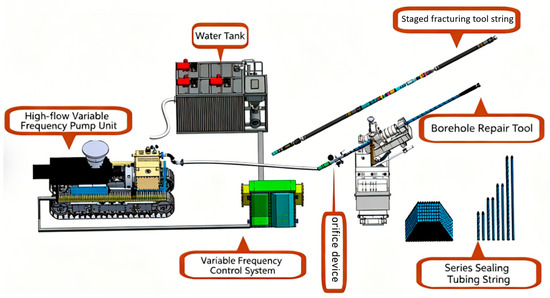
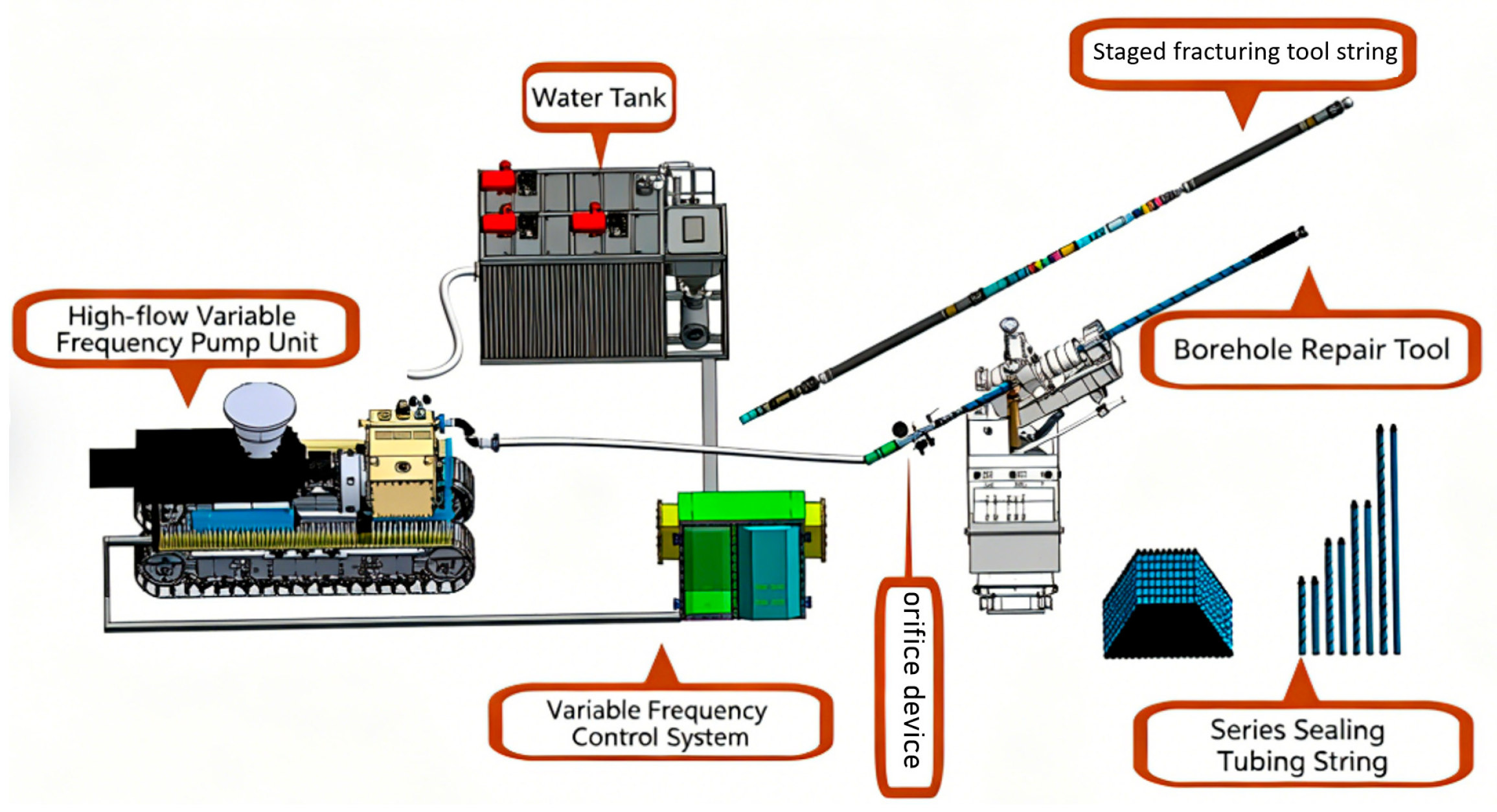
To ensure the smooth implementation of the above fracturing scheme, dedicated BZW series hydraulic fracturing complete sets were selected and matched for the geological conditions of deep high in situ stress and hard rock layers in Yuanzigou Coal Mine, as shown in Figure 10. This set of equipment underwent rigorous suitability verification and can meet the complex working condition requirements of long-distance, large-depth, multi-stage fracturing.
Figure 10.
Schematic Diagram of the BZW Series Hydraulic Fracturing Complete Set.
The BZW250/50 type water injection pump is selected as the power core of the system. The pump group is a type of special equipment specially designed for the harsh working conditions of the coal mine. The maximum output pressure of 50 MPa and the rated flow rate of 250 L/min can provide a continuous and stable power source for the fracturing fluid to split in the hard sandstone layer. The pump unit adopts a compact design, with an overall size of 2600 × 1500 × 1500 mm and a total weight of 2.5 tons. It not only meets the space limitation of underground transportation and installation but also ensures the stability of equipment operation.
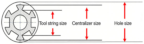
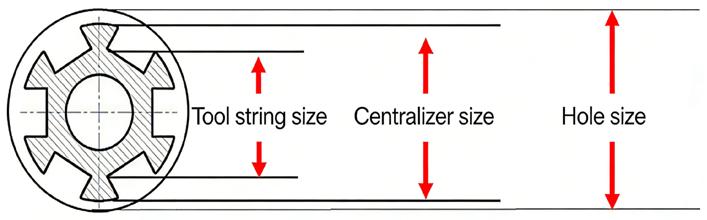
The core actuator in the drilling hole adopts a special tool string composed of the MKY70 recoverable packer and 73MFG1500 fracturing sealing string, as shown in Figure 11. The packer has an outer diameter of 105 mm and a length of 2370 mm. Its structural design fully considers the passability and setting reliability in the bare hole. In particular, it is worth emphasizing the supporting research and development of the staged fracturing tool string system. The system realizes the accurate ‘centering’ positioning of the tool string in the borehole through the optimal combination of auxiliary tools such as centralizers and anchors.
Figure 11.
Schematic Diagram of Downhole Tool String Configuration.
Regarding high-pressure fluid control, the wellhead assembly selected the KY01 fracturing-specific equipment. Its working pressure of 60 MPa and minimum burst pressure of 120 MPa, combined with impact and vibration resistance design, provide reliable safety assurance for underground high-pressure operations. The connecting pipelines utilize R15-25 type multi-layer steel-wire-wound high-pressure hoses. These hoses also possess a pressure-bearing capacity of 60 MPa and a burst pressure of 120 MPa. Their internal diameter of 25 mm balances flow requirements and flexibility needs, adapting to complex spatial layouts underground.
The selection of the entire equipment system fully considered the special operating environment of underground mines. Through optimized parameter matching between components, a complete engineering technical solution was formed, providing strong hardware support for achieving the designed 120-stage fracturing construction.
5. Comprehensive Monitoring and Evaluation of Hydraulic Fracturing Effects
5.1. Field Observation and Analysis of Fracturing Influence Range
After completing the staged fracturing construction of the roof directional long boreholes, a multi-method comprehensive monitoring approach was adopted to accurately evaluate the actual propagation range of the fractures and the pressure relief effect. Through systematic observation of roadway surrounding rock morphology, statistics of water outflow points from fractures, and tracking monitoring of the stress state of support components, first-hand evidence of the fracturing influence range was obtained.
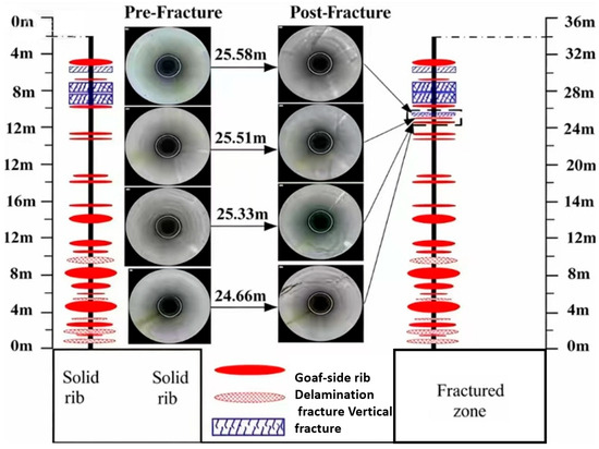
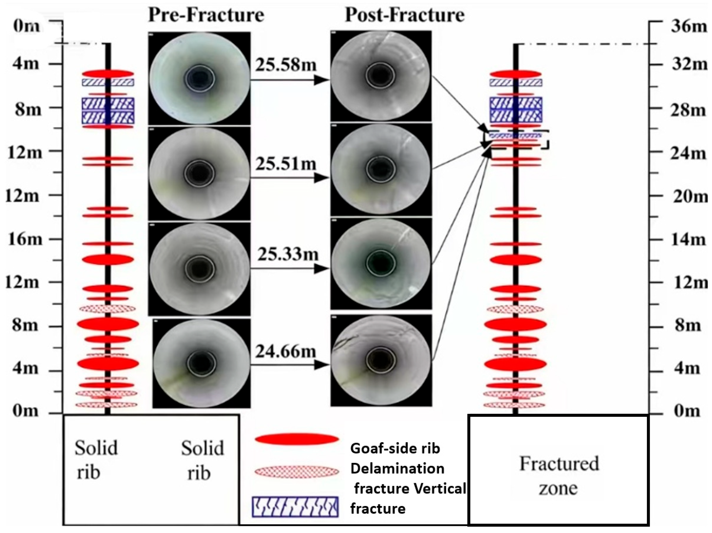
Borehole imaging observations conducted in the fracturing area of the 1930 m drilling field showed that the degree of fracture development in the roof rock layers significantly increased after fracturing, as shown in Figure 12.
Figure 12.
Fracture Development in the Roof Before and After Fracturing.
Field observations revealed obvious dynamic responses in the roadway after fracturing. On both sides of the fracturing boreholes, in the roadway ribs and roof areas, varying degrees of water seepage and dripping occurred. In some areas, bolts and anchor cables were pulled out or broken, and water inflow was observed in gas drainage holes. These phenomena collectively indicate that the fracturing action led to the redistribution of the stress field within the roof and coal mass, inducing adjustments in the rock mass structure. By systematically measuring the spatial distribution range of these response characteristics, it was determined that the maximum fracturing influence radius could reach 27.8 m. This data provides an important reference for the optimization of subsequent fracturing parameters.
The hydraulic fracturing influence radius R is determined by on-site water outlet monitoring. During hydraulic fracturing, the high-pressure water cracks the coal–rock mass to form a connected fracture network. When the fracture extends to the free surface of the roadway roof and sides, water will gush out at the corresponding position, which is the water outlet point. The horizontal distance from each water outlet point to the fracturing borehole is measured, and the average value is taken as the final hydraulic fracturing influence radius, calculated by the formula:
where ri is the horizontal distance from the i-th water outlet point to the fracturing borehole, and n is the total number of measured water outlet points. The water outlet point directly reflects the actual propagation range of the hydraulic fracture, so the distance from the water outlet point to the borehole essentially represents the local fracturing influence radius, and the average value can eliminate the influence of coal–rock mass heterogeneity, making the result more representative of the overall effective fracturing range.
5.2. Evaluation of Pressure Relief Effect Based on Microseismic and Stress Monitoring
To quantitatively evaluate the pressure relief effect of fracturing, a three-dimensional monitoring network combining surface microseismic ARP monitoring stations and underground microseismic monitoring systems was established, focusing on analyzing the spatiotemporal evolution patterns of microseismic events before and after fracturing.
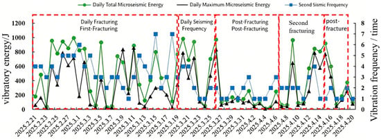
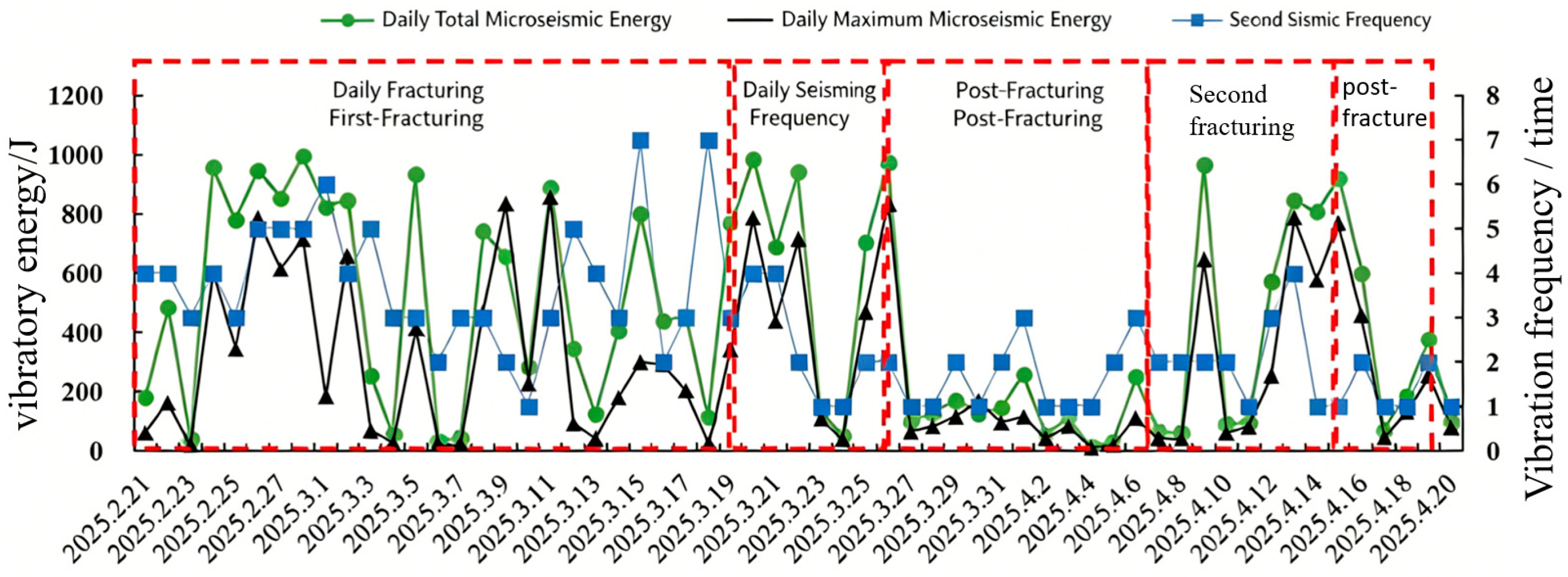
Monitoring data showed that after implementing staged fracturing through directional long boreholes in the roof at the 1930 m drilling field, the characteristics of microseismic activity changed significantly. As shown in Figure 13, the average daily frequency of microseismic events decreased by 50.65%, and the average daily total energy release decreased by 27.73% after fracturing. This pattern of change indicates that the fracture network pre-created in the roof rock layers through hydraulic fracturing effectively released the long-term accumulated elastic energy in the thick, hard roof, reducing the risk of sudden energy release during mining.
Figure 13.
Evolution of Microseismic Energy and Frequency.
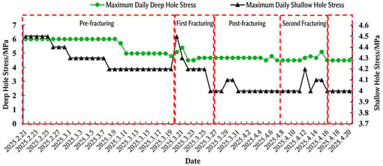
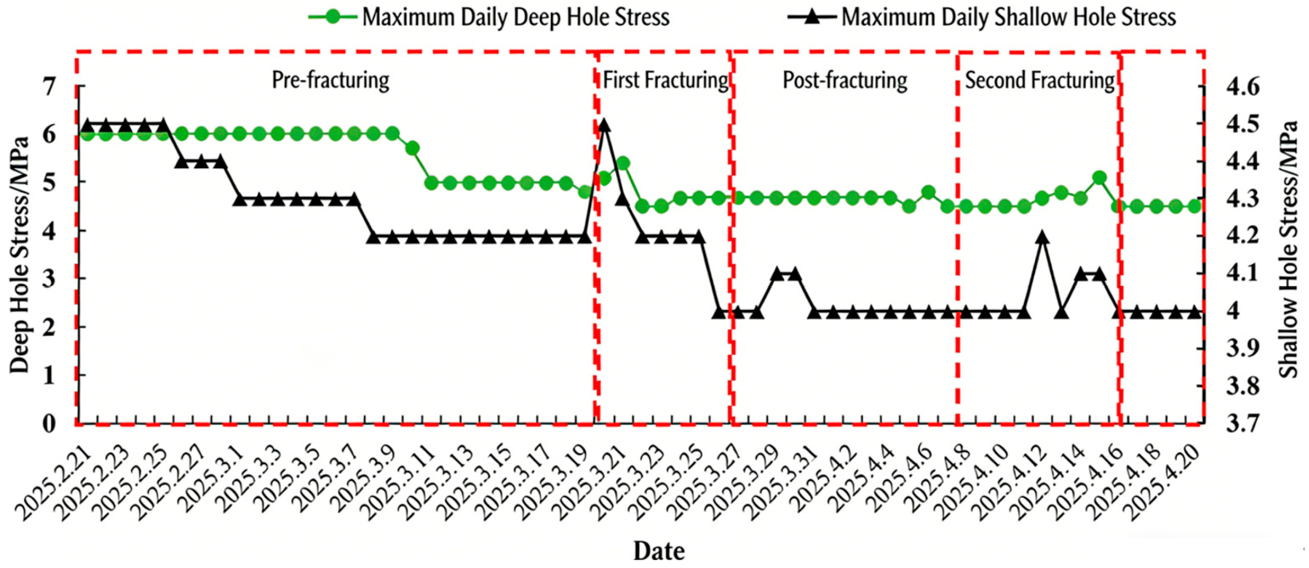
Stress monitoring data further verified the pressure relief effect of fracturing. Through continuous monitoring of the stress state in the deep and shallow parts of the roadway, it was found that after fracturing implementation, the surrounding rock stress in the roadway showed a downward trend. As shown in Figure 14, the 33-day average stress value at the deep monitoring point decreased from 5 MPa to 4.68 MPa, a reduction of 6.8%; the average stress value at the shallow monitoring point decreased from 4.2 MPa to 4.07 MPa, a reduction of 3%. The stress reduction in the deep part was significantly greater than that in the shallow part, a phenomenon consistent with the mechanical principle that fracturing primarily affects the deep rock mass of the roof.
Figure 14.
Evolution of Surrounding Rock Stress in the Roadway.
Comprehensive results from microseismic and stress monitoring lead to the conclusion that the directional long-borehole staged hydraulic fracturing technology effectively changed the stress state and energy accumulation mode of the roof rock mass in the 1012006 working face, achieving the expected pressure relief and rockburst prevention effect. This comprehensive evaluation method based on multi-parameter monitoring provides a reliable technical approach for the quantitative assessment of the pressure relief effect of hydraulic fracturing in hard roofs.
6. Conclusions
(1) To address the hard roof hanging and rockburst risk faced by the 1012006 working face in Yuanzigou Coal Mine, geological drilling precisely identified the low-position key stratum (Key Stratum 2), which was approximately 23 m above the roadway roof, as the target layer for hydraulic fracturing. As the core rock layer controlling the near-field roof structure and lateral hanging roof, its successful weakening is the key to cutting off the “F-shaped” spatial structure and achieving advanced pressure relief.
(2) True triaxial hydraulic fracturing acoustic emission experiments revealed the intrinsic relationship between rock mass fracturing and acoustic emission activity during the fracturing process: a sudden drop in injection pressure and a simultaneous leap in acoustic emission ring-down counts are direct indicators of macroscopic fracture formation; by contrast, high-energy acoustic emission events specifically point to the rupture of high-strength rock layers. The surge in acoustic emission count corresponds to the intensive occurrence of micro-fractures in the rock mass. In field practice, we use this feature point as a sign of ‘effective seam making’. Accordingly, we can dynamically adjust the water injection pressure to ensure fracture propagation while avoiding large dynamic disasters induced by excessive pressure, or determine the timing of pump shutdown/depressurization to prevent energy waste or engineering risks caused by excessive fracturing. This experimental conclusion provides an intuitive monitoring basis for real-time optimization of on-site construction parameters.
(3) Based on the “dual-borehole synergy” differentiated layout principle, a three-dimensional fracturing network consisting of 6 drilling fields and 12 directional long boreholes was designed, with a total fracturing footage of 5727 m and 120 planned fracturing stages. The supporting specialized equipment, including the BZW250/50 injection pump and MKY70 retrievable packer, met the process requirements for long-distance, multi-stage fracturing under conditions of deep boreholes and high in situ stress.
(4) Microseismic and stress monitoring data indicate that the energy accumulation and stress concentration state of the roof rock mass were significantly improved after fracturing. The average daily frequency and total energy of microseismic events decreased by 50.65% and 27.73%, respectively; the observed stress value in the deep part of the roadway decreased by 6.8%. This confirms that pre-setting a fracture network can effectively release the elastic energy of the roof, alter mining-induced stress distribution, and achieve the engineering goal of reducing the risk of strong strata pressure manifestation.
Author Contributions
Conceptualization, Z.Y. and L.D.; methodology, Z.Y. and T.F.; validation, Z.Z. and W.W.; formal analysis, Z.Y., T.F. and L.D.; investigation, Z.Y. and T.F.; resources, Z.Y., T.F. and Z.Z.; data curation, Z.Y., T.F. and L.D.; writing—original draft preparation, Z.Y., T.F. and L.D.; writing—review and editing, Z.Y., T.F., L.D. and W.W.; visualization, T.F.; supervision, Z.Z. and W.W.; project administration, Z.Z.; funding acquisition, Z.Y., L.D., Z.Z. and W.W. All authors have read and agreed to the published version of the manuscript.
Funding
This study was supported by the National Key Research and Development Program of China (2023YFC3009003), the Natural Science Foundation of Chongqing (CSTB2024NSCQ-MSX0010), the Key Project of Science and Technology Innovation and Entrepreneurship Fund of Tiandi Technology Co., Ltd. (2023-2-TD-ZD001, 2025-TD-QZ027), and the Independent Project of China Coal Technology and Engineering Group Chongqing Research Institute (2023YBXM38, 2024ZDYF18).
Data Availability Statement
The authors declare that all data supporting the findings of this study are available within the article.
Conflicts of Interest
Authors Zhuangzhuang Yao, Tianxin Feng, Linchao Dai, Zhigang Zhang and Wenbin Wu are employed by the company Tiandi Technology Co., Ltd. The remaining authors declare that the research was conducted in the absence of any commercial or financial relationships that could be construed as a potential conflict of interest. The authors declare that this study received funding from the company Tiandi Technology Co., Ltd. The funder was not involved in the study design, collection, analysis, interpretation of data, the writing of this article or the decision to submit it for publication.
References
- Xie, H. Research framework and anticipated results of deep rock mechanics and mining theory. Adv. Eng. Sci. 2017, 49, 1–16. [Google Scholar]
- Liu, X.; Jia, X.; Yang, T.; Nie, B.; He, C.; Li, C.; Bao, S. Study on the mechanism of permeability enhancement in coal beds fractured by HVEP: Cross-scale transportation of CBM. Green Smart Min. Eng. 2025, 2, 402–412. [Google Scholar] [CrossRef] [Scilit]
- He, M.C.; Xie, H.P.; Peng, S.P.; Jiang, Y.D. Study on rock mechanics in deep mining engineering. China J. Rock Mech. Eng. 2005, 24, 2803–2813. [Google Scholar]
- Qi, Q.X.; Li, Y.Z.; Zhao, S.K.; Zhang, N.; Zheng, W.; Li, H.T.; Li, H.Y. Seventy years development of coal mine rock burst in China: Establishment and consideration of theory and technology system. Coal Sci. Technol. 2019, 47, 1–40. [Google Scholar]
- Huang, B.X.; Zhang, N.; Jing, H.W.; Kan, J.G.; Meng, B.; Li, N.; Xie, W.B.; Jiao, J.B. Large deformation theory of rheology and structural instability of the surrounding rock in deep mining roadway. J. China Coal Soc. 2020, 45, 911–926. [Google Scholar]
- Feng, Y.J.; Kang, H.P. Test on hard and stable roof control by means of directional hydraulic fracturing in coal mine. China J. Rock Mech. Eng. 2012, 31, 1148–1155. [Google Scholar]
- Yu, B.; Zhu, W.B.; Gao, R.; Liu, J.R. Strata structure and its effect mechanism of large space stope for fully-mechanized sublevel caving mining of extremely thick coal seam. J. China Coal Soc. 2016, 41, 571–580. [Google Scholar]
- Wang, K.; Kang, T.H.; Li, H.T.; Han, W.M. Study of control caving methods and reasonable hanging roof length on hard roof. China J. Rock Mech. Eng. 2009, 28, 2320–2327. [Google Scholar]
- Dou, L.; Lu, C.; Mou, Z.; Qin, Y.H.; Yao, J.M. Intensity weakening theory for rock burst and its application. J. China Coal Soc. 2005, 30, 690–694. [Google Scholar]
- Pan, Y. Disturbance response instability theory of rock burst in coal mine. J. China Coal Soc. 2018, 43, 2091–2098. [Google Scholar]
- Tan, Y.; Zhang, M.; Xu, Q.; Guo, W.; Yu, F.; Gu, S. Study on occurrence mechanism and monitoring and early warning of rock burst caused by hard roof. Coal Sci. Technol. 2019, 47, 166–172. [Google Scholar]
- Jiang, Y.; Zhao, Y. State of the art: Investigation on mechanism, forecast and control of coal bumps in China. China J. Rock Mech. Eng. 2015, 34, 2188–2204. [Google Scholar]
- Chen, Y.; Hao, S.; Chen, Y.; Zhang, Z.; Wu, L.F.; Liu, H.L. Study on the application of short-hole blasting with guide hole to roof cutting pressure relief of gob-side entry retaining. J. Min. Saf. Eng. 2015, 32, 253–259. [Google Scholar]
- Hu, C.; Wang, J.; He, M.; Wang, X.; Wang, J.; Zhang, Z. Study on key parameters of self-formed roadway without coal pillar by roof cutting and pressure relief in medium and thick coal seam. Coal Sci. Technol. 2022, 50, 117–123. [Google Scholar]
- Liu, Z.; Cai, F.; Xiao, Y. Numerical simulation and analysis of effect of stress release and permeability improvement in coal seams by deep-hole. J. Anhui Univ. Sci. Technol. (Nat. Sci.) 2008, 28, 16–20. [Google Scholar]
- Kang, H.; Feng, Y. Hydraulic fracturing technology and its applications in strata control in underground coal mines. Coal Sci. Technol. 2017, 45, 1–9. [Google Scholar]
- Kang, H.; Feng, Y.; Zhang, Z.; Zhao, K.; Wang, P. Hydraulic fracturing technology with directional boreholes for strata control in underground coal mines and its application. Coal Sci. Technol. 2023, 51, 31–44. [Google Scholar]
- Liu, J.; Huang, X.; Yang, M. Current status and prospects of horizontal well staged fracturing tools and technologies. Pet. Mach. 2021, 49, 110–119. [Google Scholar]
- Guo, C.; Shen, D.; Zhang, C.; Guo, C.; Wang, S. Key technology and application of controlled hydraulic fracturing in underground coal mine. Coal Sci. Technol. 2015, 43, 114–118, 122. [Google Scholar]
- Zhou, J. Application practice of horizontal well segmental fracturing technology in CBM exploitation. China Coal Geol. 2019, 31, 27–30. [Google Scholar]
- Xu, Y.; Guo, S. Technology and application of staged fracturing in coalbed methane horizontal well of soft and hard coal composite coal seam. J. China Coal Soc. 2019, 44, 1169–1177. [Google Scholar]

Disclaimer/Publisher’s Note: The statements, opinions and data contained in all publications are solely those of the individual author(s) and contributor(s) and not of MDPI and/or the editor(s). MDPI and/or the editor(s) disclaim responsibility for any injury to people or property resulting from any ideas, methods, instructions or products referred to in the content. |
© 2026 by the authors. Licensee MDPI, Basel, Switzerland. This article is an open access article distributed under the terms and conditions of the Creative Commons Attribution (CC BY) license.