1. Introduction
The discipline of mechanical engineering (ME) relies on digital architecture provided by Computer-Aided Design (CAD). Contemporary CAD systems extend far beyond simple tools for drafting; they are indispensable platforms integrating complex three-dimensional modeling, finite element analysis (FEA), parametric manipulation, and crucial integration points with advanced manufacturing technologies [
1]. This radical transformation in the engineering workflow is directly motivated by industry mandates: the necessity to accelerate iterative design cycles, reduce time-to-market intervals, and achieve rigorous optimization of both structural integrity and material efficiency, particularly within safety-critical and high-performance sectors [
2]. The benefits of CAD are plain, including significant cost reductions, shorter development cycles, improved product quality, and the ability to rapidly adapt designs to meet changing requirements or constraints. Moreover, CAD serves as an enabler of innovation by providing a platform where cutting-edge technologies can converge. Its integration with virtual and augmented reality opens new horizons for immersive visualization and collaborative design, artificial intelligence enhances decision-making through generative design and automated error detection, and additive manufacturing leverages CAD models directly to create complex, customized structures [
3] that were once impossible to fabricate. Together, these advances are expanding the frontiers of what can be achieved in mechanical engineering, fostering a new era of smart, sustainable, and highly efficient product development.
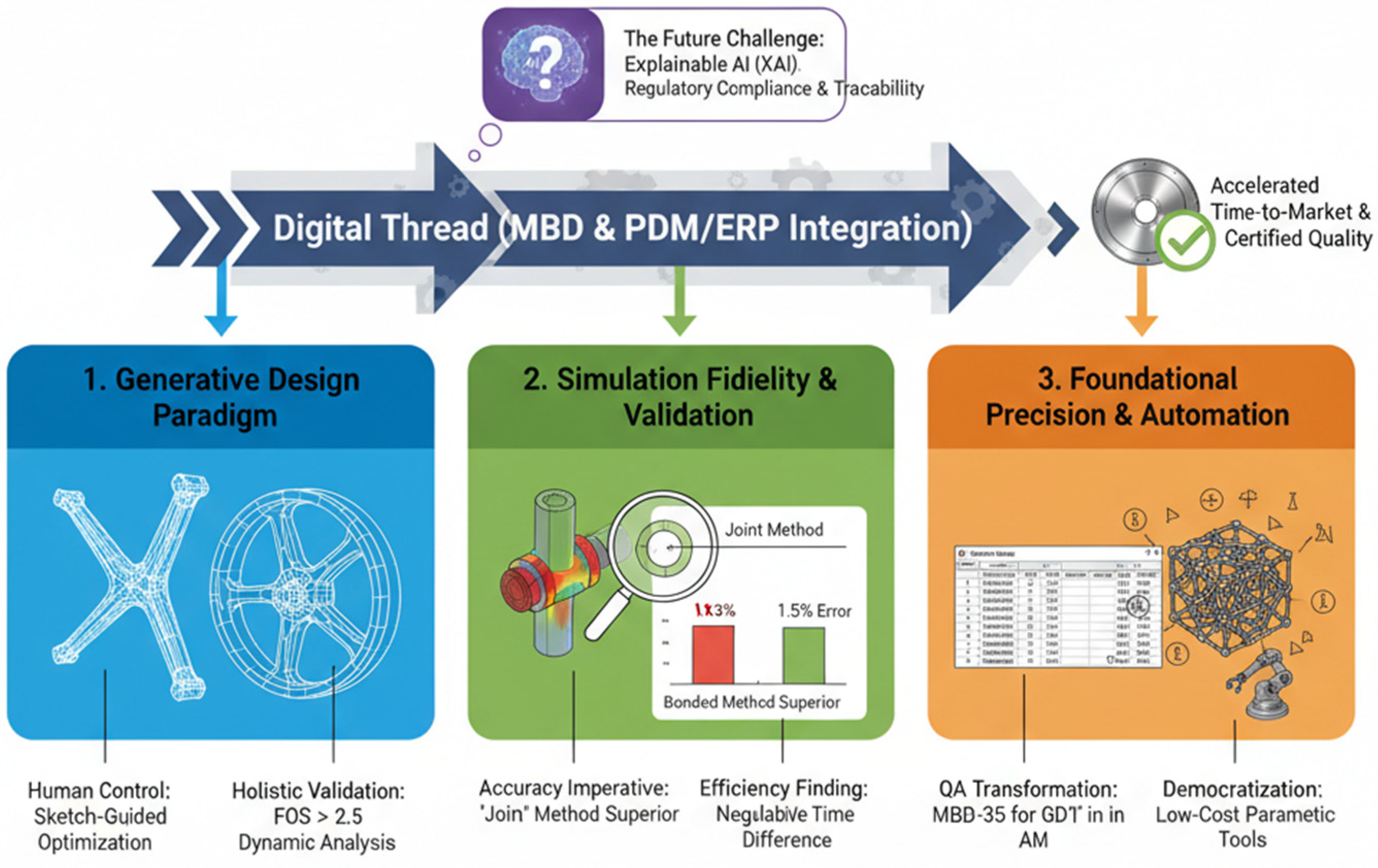
This Special Issue provides a comprehensive overview of the digital thread’s current state in ME, presenting novel research that collectively defines the next wave of computational design and manufacturing methodologies. The featured contributions cluster around three interconnected and critical themes. The first theme, related to precision in advanced modeling and Quality Assurance (QA), addresses the fundamental challenge of ensuring geometric accuracy, covering methodologies ranging from proprietary tool profiling techniques to the rigorous establishment of quality frameworks, such as the challenging integration of Geometric Dimensioning and Tolerancing (GD&T) with Additive Manufacturing (AM). The second theme focuses on the revolutionary shift toward sophisticated generative techniques, showcasing advancements that include human-guided and AI-enhanced Topology Optimization (TO) alongside the development of specialized parametric algorithms for creating complex, customized structures. The third theme is related to simulation fidelity and dynamic behavior validation: it explores the absolute necessity of employing rigorous computational and experimental methods to validate dynamic performance, ensuring that digital predictions reliably mirror real-world structural behavior (see
Figure 1).
2. Contributions Overview
The articles collected in this Special Issue emphasize an intense industry shift toward customizability, efficiency, and computational rigor in ME design. The range of expertise presented spans from highly technical geometric methodologies to large-scale system integration, as summarized in
Table 1.
In [
4], a high-precision geometric design required for internal thread-milling cutters is addressed. This work focused on validating the Tangent Circles Method, a graphical profiling technique proposed as an industrially viable and simpler alternative to mathematically complex analytical methods. The comparison demonstrated a “good match” between the profiles derived graphically using CAD software (SolidWorks 2022) and those calculated analytically, confirming deviations were within acceptable manufacturing limits. By effectively democratizing the design process for precision tooling, the method accelerates the design cycle while ensuring the quality of the resulting thread profile. The study confirmed that technological factors like rake angle and relief height also significantly influence the final tool geometry.
The authors in [
5] presented a comprehensive methodology for the automated design and parametric modeling of excavator buckets within a CAD environment. The core innovation utilized the configuration abilities of a single 3D model to efficiently manage numerous product variants—ranging broadly in length (600 mm to 2000 mm), features, and type/number of teeth. Quantitative results validated that this parametric approach drastically reduced the overall number of unique models (e.g., from 95 to 35 parts) and corresponding modeling errors by over 50% compared to traditional methods. Crucially, the methodology includes an automated design documentation algorithm that seamlessly integrates the authoritative CAD models with enterprise-wide PDM and ERP systems, ensuring data consistency across the entire digital thread.
The research carried out in [
6] introduced a novel multi-solution Topology Optimization (TO) aimed at boosting both the diversity of generated designs and the human designer’s control. It proposed integrating human-provided free-hand sketches as quantifiable geometric constraints, separating them into a stroke-based undirected boundary constraint and a closed-shape-based regional constraint. This dual-constraint approach, paired with Fourier mapping-based length-scale control, allows for the flexible manipulation of structural aesthetics without excessively sacrificing mechanical performance. Diversity is enhanced by randomly perturbing internal parameters (like Fourier frequencies) across parallel TO processes. The framework successfully generates diverse, high-performance design sets for components like wheel spokes, shifting optimization from a singular objective to a controllable design exploration.
The authors in [
7] focused on applying Topology Optimization (TO) to a highly dynamic component—an internal combustion engine connecting rod—with stringent constraints. The objective was to minimize mass and von Mises stress while maintaining a Factor of Safety (FOS) above 2.5, moving beyond simple mass reduction. The optimization process successfully achieved a 5.66% mass reduction from the original design and a 6.25% reduction in maximum von Mises stress. The design was rigorously validated by linking the static TO to a multi-body dynamic analysis (at 1000 rpm) to extract realistic motion loads, followed by a Goodman fatigue life analysis. The final component confirmed long-term durability, with FOS remaining above the critical threshold even at one million cycles.
Reference [
8] systematically analyzed the impact of six different FEA bolt connection methods (e.g., bonded, joint, beam) on predicting the dynamic behavior of a structure (a headlamp vibration test jig) against an experimental benchmark. It confirmed that common bonded methods significantly overestimate the natural frequency (544.1 Hz vs. 493.2 Hz experimental), largely due to assumptions of excessive stiffness. The research identified the Joint connection method as the most accurate, achieving a minimal frequency deviation of only 7.6 Hz (a 1.5% error). While bonded methods were the fastest in terms of computational time, the study demonstrated that for high-fidelity dynamic modeling, the minimal extra computing cost of the Joint method yields a massive gain in simulation accuracy.
In the Perspective paper [
9], the author outlined the critical challenges and necessary adaptations for integrating established Geometric Dimensioning and Tolerancing (GD&T) principles with Additive Manufacturing (AM) technologies. It highlighted how AM’s characteristics—including complex freeform geometries, anisotropic properties, and process-induced variances like warping—break traditional subtractive-based GD&T models. Key advancements proposed include the development of functional datum systems and surface profile tolerancing for non-Euclidean shapes, shifting to area-based surface texture parameters, and the introduction of formalized distinctions between as-built and post-processed tolerances. Fundamentally, the paper advocates for the urgent adoption of Model-Based Definition (MBD) into the Digital Thread to embed all GD&T information directly into the authoritative 3D model.
The authors in [
10] addressed the need for accessible tools in Design for Additive Manufacturing (DfAM) by developing custom, semi-automatic Grasshopper algorithms (Rhino 8) for generating sophisticated, strut-based gradient and conformal lattice structures. This low-cost approach challenges the reliance on expensive, proprietary commercial software packages for complex lightweighting solutions. Through three-point bending tests on PA2200 specimens, the research quantified the performance impact of various design parameters. The most significant finding was that Conformity (structures conforming to the boundary geometry) and maximized Strut Diameter positively dominated the resulting load-bearing capacity (force/weight ratio). The work validates the feasibility of democratizing advanced DfAM functionality within customizable parametric modeling environments.
Reference [
11] proposes an intelligent process planning framework for shaft-type components that directly bridge CAD geometry and executable machining routes through multi-graph representations. By combining machining feature recognition, process scheme decision-making, and route planning within a unified graph-based architecture, the approach demonstrates how advanced CAD data can be systematically enriched with manufacturing semantics and process constraints. The high reported accuracies in feature recognition and process route generation confirm the potential of graph neural networks to enhance automation, consistency, and decision reliability in CAD/CAM integration, reinforcing the broader trend toward data-driven and intelligent design-to-manufacturing pipelines highlighted throughout this Special Issue.
3. Research Questions and Main Findings
Based on the work of the authors in this Special Issue, a number of research questions and solutions are proposed to stimulate future research in this field.
3.1. Towards Manufacturing Precision
In today’s industrial landscape, the search for precision in manufacturing is more than a technical goal. Advancements in CAD, digital technologies, automation, and data-driven processes are transforming manufacturing into a discipline where accuracy defines success. Moving towards manufacturing precision means reducing variability, optimizing resources, and delivering products that meet exacting standards while enabling sustainable growth. In this context, the authors of [
4] declared that the main research question for high-precision chip-removal processes (such as thread milling) relies in the accurate profiling of the cutting tool as an absolute prerequisite. The traditional analytical methods used to achieve this precision are often mathematically laborious, complex, and computationally intensive, creating a persistent barrier to their widespread industrial adoption. The research presents a solution by validating the Tangent Circles Method, a graphical profiling technique designed for implementation within a standard CAD system, specifically addressing internal thread-milling cutters. The graphical methodology replaces complex equations by defining a series of tangent circles (profiling circles) to an Archimedean spiral (which represents the thread profile in the cross-section). The centers of these circles lie precisely on the specified trajectory of the tool center. The core validation involved comparing the geometric parameters that were graphically derived with the results obtained from complex analytical equations. The comparison demonstrated a “good match,” confirming that the resulting profile deviations were within acceptable manufacturing limits. This outcome validates the Tangent Circles Method as being both mathematically sound and industrially viable.
3.2. Enhancing Modeling Efficiency Through Parametric Automation and PDM/ERP Integration
The engineering challenges in managing extensive product lines are characterized by high-variability results in model proliferation, redundant efforts, and a significant increase in potential design errors [
12]. To deal with the relevant research question, a methodology is introduced that fundamentally addresses this issue by leveraging parametric modeling via configurations within a CAD system such as SolidWorks 2022 [
5].
This approach is exemplified by its application to excavator buckets, which range broadly from Class A to Class M with lengths spanning 600 mm to 2000 mm. Components, including the Base Part and Upper Part, are designed parametrically, allowing diverse product versions to be managed within a single 3D model. The quantifiable efficiency gains are substantial. Comparative data confirms a reduction in the total number of unique models required, shrinking from 95 parts in the traditional approach to only 35 parts, resulting in average time-savings of over 50% for modeling (e.g., 65 h reduced to 34 h for parts). Crucially, this reduction in manual effort yields a proportional reduction in observed modeling errors.
The proposed methodology formalizes the link between CAD and enterprise-wide systems. It explicitly incorporates the integration of CAD models with Product Data Management (PDM) systems (such as SolidWorks PDM 2022) and Enterprise Resource Planning (ERP) systems (such as RDS ERP). While this initial setup requires a high upfront investment in specialized knowledge, the resultant long-term benefit is a non-linear scaling of design efficiency. PDM/ERP integration transforms the engineering process from a sequence of compartmentalized tasks into an integrated system where manufacturing and logistics (e.g., Supplies and Production) instantly access accurate, verified design data. This approach establishes the CAD model as the authoritative data source for the entire enterprise, reinforcing the Digital Thread concept and delivering systemic efficiency through centralized data management and improved traceability, which is vital for accelerating time-to-market.
3.3. Next Generation Topology Optimization: Human Control and Dynamic Evaluation
Topology Optimization (TO) is widely adopted to generate high-performance structures, typically aiming to minimize compliance under volume constraints [
13]. However, traditional TO algorithms suffer from two main limitations: limited human controllability over design features and insufficient solution diversity, often necessitating burdensome manual redesign iterations. To deal with this issue, a novel sketch-guided, multi-solution TO framework is proposed in [
7] to overcome these limitations by intentionally integrating human aesthetic input and computational randomness. This framework operates by codifying intuitive human aesthetic and stylistic preferences (expressed via sketch) as soft, quantifiable geometric constraints that are designed to dynamically compete with the primary engineering objective (performance/compliance minimization).
The framework uses dual control strategies, integrated with Fourier mapping-based length-scale control: a Stroke-based undirected structural boundary constraint ensures the structural boundaries align with sketched strokes. This constraint preserves design freedom in adjacent regions and is vital for promoting design diversity and helping the algorithm escape localized optima, although it may result in a slight increase in compliance. A closed-shape-based regional constraint drives material uniformity within a closed sketch contour. This constraint effectively stabilizes structural features and approximates a hard constraint when given a large weight coefficient, although its use tends to reduce solution diversity. Diversity is significantly enhanced by running multiple parallel TO processes where two key parameters are randomly perturbed: the Fourier mapping frequencies and the load force magnitudes. This strategy manages the adversarial relationship between aesthetic control and the optimization objective to produce a set of diverse, high-performing solutions. The result is that the designer shifts from passively accepting one singular optimal solution to actively exploring a Pareto front defined by both performance metrics and human-defined aesthetic criteria.
Reference [
7] explores the potential of next generation TO with particular focus on its application in highly dynamic components within internal combustion engines, such as connecting rods, mandates a stringent validation process that extends far beyond standard static stress analysis. A rigorous workflow is presented that systematically integrates mass/stress minimization (using the Solid Isotropic Material with Penalization or SIMP method in ANSYS Discovery 2024 R2) with an extensive post-optimization validation incorporating rigid body dynamics, transient analysis, and fatigue life analysis. The optimization successfully targeted mass reduction and maximum von Mises stress minimization, while simultaneously adhering to the critical constraint of maintaining a reliable factor of safety.
This research strongly emphasizes that for highly dynamic systems, successful TO is insufficient without rigorous, multi-physical validation that accounts for static compression, complex dynamic/inertial loads, and longevity. Critically, the study found that excessive mass reduction leads to noticeable engine imbalance and increased vibration due to a disturbance in the inertial balancing ratio between the connecting rod mass and the crankshaft counterweight. This reinforces that optimization in dynamic systems must be a holistic process constrained by kinematic and inertial requirements, not merely compliance and volume.
A complementary research direction emerges at the interface between CAD and manufacturing planning [
11], where graph-based artificial intelligence methods extend design intelligence beyond geometry toward automated decision-making across the downstream stages of production. In this context, CAD models are no longer treated as static repositories of shape information, but as structured data sources enriched with manufacturing semantics, process constraints, and operational knowledge. By leveraging graph representations and learning-based reasoning, these approaches enable the automatic selection of machining schemes and the generation of consistent process routes directly from design data, reinforcing the role of CAD as the central driver of an integrated, intelligent design-to-manufacturing pipeline.
3.4. Integrating Quality Control in Design for Additive Manufacturing: The Challenge of GD&T Standardization
Additive Manufacturing (AM) enables the creation of highly innovative and complex geometries, such as lattice structures, gyroids, and inaccessible internal channels [
14]. Simultaneously, AM processes introduce undesired effects to be controlled, such as anisotropic material properties, thermal distortion, warping, and shrinkage [
15]. These factors challenge the core tenets of Geometric Dimensioning and Tolerancing (GD&T), which was historically developed and standardized for subtractive processes. Traditional GD&T standards struggle with non-Euclidean surfaces, where defining datum systems for freeform shapes is non-trivial; anisotropy, where layer-by-layer fabrication causes significantly rougher surfaces in the vertical/build direction; and inspection limitations, where internal features are inaccessible to traditional Coordinate Measuring Machines (CMMs).
This situation is not merely a metrology issue; it represents a fundamental challenge to the industrial scalability and certification of AM parts. Without robust, unambiguous, and standardized tolerancing, the innovative designs generated by DfAM tools cannot move reliably into regulated mass production [
9], especially when integrated into complex assemblies alongside subtractive manufactured components. To address this critical bottleneck, the perspective highlights several necessary adaptations in GD&T practice:
A transition toward functional datum systems and surface profile tolerancing for freeform geometries, validated using non-contact metrology like point cloud analysis or mesh comparison.
The evolution of surface roughness standards, shifting focus from traditional line-based parameters (, ) to area-based parameters (, ), which are far better-suited to characterizing complex, anisotropic AM surfaces.
The formal integration of manufacturing fidelity requirements by distinguishing between as-built tolerances (raw AM surface finish) and post-processed tolerances (tighter limits achieved through secondary operations).
The solution requires fully integrating Model-Based Definition (MBD) into the Digital Thread. MBD embeds all GD&T information, material specifications, and necessary annotations directly into the 3D model, eliminating the reliance on ambiguous 2D drawings. This integration facilitates automated tolerance checks during build simulation and enables advanced inspection techniques to verify the component directly against the CAD source, ultimately unlocking the full potential of complex generative designs for industrial scale.
3.5. Customization and Conformity in Design for Additive Manufacturing
The capacity to design complex, functionally graded lattice structures is traditionally restricted by reliance on highly specialized, expensive commercial software (e.g., nTopology nTop or Altair Inspire Personal Edition), creating significant financial and accessibility barriers for research and small firms. As already mentioned, a methodology is developed in [
10] for generating customized, semi-automatic Grasshopper algorithms (a Rhino 8 plugin) to generate gradient, conformal, strut-based lattice structures, offering a low-cost, customizable alternative. The custom algorithm leverages native Grasshopper functions combined with open-source plugins (Crystallon V2.0, Dendro V0.9.0, IntraLattice V07.06, Pufferfish V2.3) to control complex parameters, including unit cell topology, conformity (conforming or non-conforming to surface geometry), and gradients in cell size or strut diameter. The functionality was subjected to quantitative experimental validation using 3-point bending tests on PA2200 arch specimens, focusing on the resulting force/weight ratio. This outcome confirms the potential of leveraging accessible parametric CAD environments with open-source extensions to achieve complex DfAM functionality previously restricted to proprietary commercial packages. This represents a significant pathway toward democratizing advanced lightweighting and material performance optimization techniques by lowering the financial and learning curve barriers.
4. Discussion
The findings of the seven papers published in this Special Issue collectively demonstrate the existence of a robust, though continuously maturing, digital engineering ecosystem in ME:
Validation Requires Multi-Physical Integration: The development of high-performance components demands that validation protocols transcend disciplinary silos, linking geometry (TO) with structural mechanics (stress), dynamics (kinematics/vibration), and manufacturing feasibility.
The Trend of Accessible Customization: The industry exhibits a shift away from single dependence on monolithic software. Evidence suggests that custom, bespoke algorithms built on accessible platforms (such as Rhino/Grasshopper) can successfully deliver highly specialized DfAM results, such as conformal and gradient lattice structures, which were previously restricted to expensive commercial packages.
Data Centrality in Quality and Efficiency: Both efficiency gains and rigorous quality assurance fundamentally rely on robust, centralized data management systems (PDM/ERP) and the establishment of the CAD model, via MBD, as the single authoritative source of product data throughout its lifecycle.
The synthesized research points toward a convergence of the technologies that will define the next decade of CAD/ME practice, marked by the increasing influence of cognitive systems and the formalization of digital data pipelines. Therefore, the following areas of investigations will be the subject scientific and industrial research in the near future.
4.1. The Rise in Artificial Intelligence for Generative Design
The integration of Artificial Intelligence is one of the most frequently cited directions for CAD evolution [
16], promising to automate routine tasks, suggest methods of material optimization, and provide predictive insights by learning from the historical data and simulation outcomes. Generative Design is concurrently expanding its reach, moving beyond simplistic mechanical constraints to integrate multi-disciplinary considerations, including thermal, electrical, and kinematic factors [
17].
However, the primary long-term challenge for the adoption of AI in ME industries (e.g., automotive and aerospace) is not technical capacity but regulatory compliance and traceability. Current AI solutions, particularly generative models (LLMs), frequently operate as “black boxes,” making it difficult to trace their engineering rationale. This lack of transparency undermines the traceability required by standards such as the Machinery Directive 2006/42/EC [
18] and ISO 12100.4 [
19].
The critical future research direction for AI in ME must focus on developing Explainable AI (XAI) models for Topology Optimization and GD&T that can provide verifiable, traceable design rationale [
20], and establishing AI-based compliance checking mechanisms to ensure automatically generated designs satisfy safety and regulatory standards before physical prototypes are manufactured.
4.2. The Evolution of Digital Thread and Digital Twin
The realization of Digital Thread is an essential condition for achieving industrial scaling in AM [
21]. The successful implementation of the digital thread hinges on fully adopting the Model-Based Definition (MBD), which ensures that GD&T annotations and other critical parameters are embedded directly into the authoritative 3D model, thereby minimizing data loss and misinterpretation across the chain (CAD, Simulation, and CAM).
High-fidelity parametric models and accurate dynamic simulations serve as the digital foundation for the Digital Twin concept. The logical progression is to integrate these virtual models with real-time operational data, allowing engineers to track wear, simulate predictive maintenance, and refine subsequent designs based on true operating conditions. Future research efforts should prioritize the integration of MBD data [
22] and parametric modeling systems with real-time operational data streams, especially for complex machinery like excavator buckets, to enable continuous, data-driven design optimization.
4.3. Gaps in Standardization and Validation Processes
The points identified across the collected research necessitate targeted efforts in the development of standards. Dealing with AM metrology, as well as the complexities of AM geometries, particularly internal features and freeform surfaces, demand further standardization of non-contact inspection techniques (e.g., Computed Tomography (CT) scanning and optical 3D scanning) to ensure reliable quality verification [
9].
When referring to dynamic modeling Standards, it is evident that the quantitative findings regarding simulation fidelity should inform industry guidelines on the preferred bolt modeling methods for highly dynamic or vibration-sensitive structures. These standards should explicitly balance the need for high accuracy (joint method) against the computational and complexity overhead (bonded method) across different design phases.
Finally, with reference to multi-material tolerancing, the current GD&T frameworks are insufficient for handling the dimensional complexity of multi-material or functionally graded AM parts, requiring new standards to establish consistent and unambiguous tolerance values. All these aspects should be considered for future research in the field of CAD for ME.
5. Conclusions
This Special Issue highlights the current trend in Computer-Aided Design for Mechanical Engineering, characterized by a search for efficiency and accuracy. The contributions collectively demonstrate significant advances:
Efficiency Through Parametric Systems [
23]: The proven feasibility of employing parametric modeling integrated with PDM/ERP systems substantially reduces design time and error for product lines with high variability, institutionalizing the digital thread.
Precision: The validation of graphical, intuitive CAD techniques, such as the Tangent Circles Method, for traditionally analytical precision tool profiling, enhances the accessibility of complex engineering geometry in standard industrial practices [
4].
Generative Intelligence: The development of novel TO frameworks successfully integrates human stylistic preferences (sketches) as functional constraints that simultaneously drive the generation of diverse, high-performance design sets, marking a pivotal step in human–machine collaboration [
24].
Rigorous Validation: The establishment of comprehensive protocols for generative designs mandates analysis across static stress, multi-body dynamics, and fatigue life for dynamic components [
25].
DfAM Maturation: The ability to generate complex, functionally graded lattice structures using customized, low-cost parametric tools challenges the dominance of high-cost commercial software and expands access to advanced DfAM [
7,
8].
Quality Assurance: The urgent need for GD&T to adapt via MBD, area-based parameters, and non-contact inspection technologies is highlighted as essential for reliably managing the complexities inherent in AM geometries [
9].
The future path of CAD in Mechanical Engineering is moving toward fully cognitive, AI-driven digital methodologies and tools, where design, manufacturing, and validation are seamlessly and intrinsically linked. This forthcoming generation of tools will rely on the foundations established here: robust parametric modeling, highly accurate simulation fidelity, and formalized digital communication. Future research efforts, particularly those aimed at resolving the fundamental regulatory and traceability challenges posed by AI, the full realization of the Digital Twin concept, and the necessary standardization of GD&T frameworks for Additive Manufacturing, will ultimately define the industrial competitiveness of the next generation of mechanical components.