


Abstract
Designing high-speed wide-angle optics for large-format mirrorless cameras presents a fundamental engineering conflict between the short flange back distance and the requirement for high-resolution aberration correction. To address this challenge, this study proposes a compact 18.5 mm F/2.0 lens system utilizing a modified retrofocus architecture equipped with an internal floating-focus mechanism. The design methodology integrates glass-molded aspherical surfaces to suppress high-order aberrations and employs passive athermalization strategies to maintain stability across a temperature range of −30 °C to +70 °C. Performance was rigorously evaluated using numerical simulations in Zemax OpticStudio, alongside comprehensive Monte Carlo tolerance analysis. Simulation results demonstrate exceptional optical performance, with the Modulation Transfer Function (MTF) exceeding 0.5 at a spatial frequency of 100 lp/mm across the field. Furthermore, focus breathing is restricted to less than 1%, and optical distortion is strictly controlled within 2%. The Monte Carlo tolerance analysis predicts a manufacturing yield exceeding 80% under standard industrial precision levels. Ultimately, this work provides a theoretically sound, athermally stable, and highly manufacturable solution suitable for next-generation high-resolution mirrorless sensors.
1. Introduction
With the rapid evolution of modern mirrorless imaging technology, market demand for wide-angle lenses that combine high performance with portability continues to rise. This trend imposes additional challenges on optical design, especially when a lens must deliver a large field of view and high image quality while maintaining a compact physical envelope. Conventional wide-angle designs are often constrained by an insufficient back focal length (BFL), which limits the space available for the image sensor and other in-body components [1,2].
The retrofocus (inverted telephoto) architecture has therefore seen extensive application in wide-angle lenses, as it enables a large field of view while lengthening the BFL. By employing a front-negative/rear-positive grouping, a retrofocus objective efficiently collects and focuses high-incidence-angle rays, thereby expanding the usable field within tight packaging constraints and providing greater flexibility for downstream optical elements [3]. However, at fast apertures and very wide fields, aberration correction remains the principal challenge for retrofocus lenses, encompassing distortion, field curvature, chromatic aberration, coma, and astigmatism [4,5].
To address the stringent requirements of high-resolution imaging systems, advances in optical design have introduced aspheric and freeform elements to mitigate these intrinsic aberrations. Such advanced optics provide greater design freedom and improved edge image quality, allowing lenses to sustain high imaging performance while pursuing compactness [6,7,8]. These technologies not only enhance optical performance but also contribute substantially to miniaturization [9,10,11].
On this foundation, the integration of computational imaging with deep learning presents new opportunities for further performance gains. Through hardware–software co-design, these approaches significantly improve the imaging pipeline, enabling excellent results even when optical design latitude is limited [12,13,14,15]. In addition, optimization methodologies such as aberration sensitivity analysis (ASA) accelerate the translation of novel optical designs into practical applications [16,17,18].
This work aims to develop a high-performance mirrorless wide-angle lens based on a retrofocus architecture, with an emphasis on achieving high image quality in a compact form and correcting complex aberrations. Detailed design analysis and optimization are performed using professional optical design software (Zemax OpticStudio 2024 R1.00; Ansys, Inc., Canonsburg, PA, USA), with the goal of providing a rigorous theoretical basis and technical guidance for the development of high-performance wide-angle lenses that address diverse market needs [19,20].
2. Materials and Methods
2.1. System Requirements and Specifications
The primary design specifications of the proposed optical system are summarized in Table 1. The lens is intended for a large-format mirrorless sensor and targets an ultra-wide diagonal field of view of approximately 85° while maintaining a compact form factor. The optimized focal length is 18.5 mm, which lies within +2.8% of the 18 mm target, at a full aperture of F/2.0. The design constrains full-field distortion within −2% to +1%, yielding approximately −1.3% barrel distortion at the diagonal field edge.
Table 1.
Design specifications of the proposed optical system.
The back focal length, including a 1.0 mm sensor cover glass, is 16.5 mm, providing sufficient clearance for a mirrorless camera package. The chief ray angle (CRA) at the sensor corner is controlled to approximately 17.5°, satisfying the ≤18° requirement for efficient microlens coupling and reduced pixel vignetting. The edge relative illumination reaches approximately 33% at F/2.0, exceeding the typical 30% threshold for acceptable corner brightness.
The lens provides a fully illuminated image circle of approximately 44 mm, with an overall optical length of about 105 mm, successfully meeting the ≤110 mm specification. Regarding resolving power, the design achieves an on-axis modulation transfer function (MTF) of 0.749 at a high spatial frequency of 100 lp/mm, which fulfills the primary target requirement of ≥0.7. Furthermore, at a mid-spatial frequency of 40 lp/mm, the MTF reaches 0.85 on-axis and is maintained above 0.60 at the field edge, ensuring excellent contrast across the entire image format.
2.2. Retrofocus Architecture and Power Distribution
To reconcile the conflict between the short focal length () and the required back focal length () for the mirrorless mechanics, a retrofocus (inverted telephoto) architecture was adopted. This configuration utilizes a front negative group and a rear positive group, which effectively shifts the principal planes rearward, thereby extending the BFL.
The optical power distribution is critical for balancing the system’s compactness with its aberration correction capabilities. While the total optical power approximates the sum of individual powers (), the specific distribution is dictated by the retrofocus architecture.
To accommodate the wide field of view () while achieving the required back focal length (), a strong negative meniscus is employed as the first element. This configuration effectively bends the off-axis chief rays, allowing the system to maintain a compact form factor despite the large aperture ( at ).
Furthermore, to ensure consistent framing during video capture, the focus breathing effect is strictly suppressed. The breathing ratio , defined as the percentage change in focal length, is controlled by an internal floating-focus mechanism:
where is the effective focal length at close focus. The optimized floating-focus structure keeps < 1%, ensuring stable framing during focusing.
2.3. Material Selection and Stop Placement Strategy
The selection of glass materials was driven by the need to balance a high refractive index with cost-effective manufacturability. High-index lanthanide glasses (e.g., H-ZLAF75A; CDGM Glass Co., Ltd., Chengdu, China) were utilized in the front group to provide strong optical power with moderate curvature, thereby reducing spherical aberration and total track length. To correct the secondary spectrum and lateral color, these were paired with high-dispersion flint glasses (e.g., H-ZLAF75A; CDGM Glass Co., Ltd., Chengdu, China) in the rear group.
The aperture stop is strategically positioned immediately after the front negative group. This “front-stop” configuration plays a dual role: it effectively limits the diameter of the large front elements, and it helps facilitate the telecentricity required for the image sensor.
2.4. Correction of High-Order Aberrations, Athermalization, and Optimization Strategy
The correction of high-order aberrations in such a fast () system is achieved through a hybrid approach combining glass choice and surface shaping.
Aspheric Optimization and Aberration Control:
Two glass-molded aspheric elements are strategically placed: one in the front group to correct distortion and coma caused by high incidence angles and one in the rear group to flatten the field. The surface sag of these even-order aspheres is governed by the standard aspheric equation [21,22,23,24]:
where represents the surface sag parallel to the optical axis, is the base curvature at the vertex, is the conic constant, is the radial distance from the optical axis, and () represent the even-order aspheric coefficients. It is worth noting that, in accordance with standard optical design conventions, the second-order coefficient is set to zero because its contribution to the optical power is inherently incorporated into the base curvature .
Achromatization and Athermalization:
Chromatic aberrations are minimized by pairing high-index crown glass with flint glass, satisfying the condition . Additionally, given the outdoor application of this lens, thermal stability is paramount. We utilized the passive optical athermalization method, ensuring that the thermal defocus satisfies
where is the refractive index, is the thermo-optic coefficient of the glass, and is the coefficient of thermal expansion (CTE) of the lens material. The terms and represent the sensitivity of the back focal length () to changes in refractive index and structural parameters (), respectively. Crucially, represents the CTE of the mechanical housing, and is the mechanical length of the barrel. By carefully matching the optical thermal drift (the sum term) with the mechanical expansion of the housing (), passive athermalization is achieved, maintaining MTF stability from to .
Optimization Strategy and Merit Function Construction:
The system was optimized using the local and global optimization algorithms in Zemax OpticStudio. The core merit function was constructed to minimize the polychromatic RMS spot radius referenced to the centroid across all sampled field angles, utilizing a Gaussian quadrature ring integration method. To meet the stringent packaging and mirrorless sensor requirements, specific boundary constraints were strictly enforced using Zemax operands. The effective focal length (EFFL) was targeted at 18.5 mm, and the total track length (TOTR) was constrained to ≤110 mm. To ensure compatibility with the image sensor’s microlens array, the maximum chief ray angle (CRA) was heavily penalized beyond using the RAID operand. Furthermore, optical distortion was tightly bound within the −2% to +1% range using the DIMX operand, while relative illumination (RELI) was constrained to remain above at the extreme field edge. Crucially, the internal floating-focus mechanism was optimized through multi-configuration modeling, dynamically constraining the focal length variation between infinity and close-focus states to suppress focus breathing strictly below +1%.
3. Results
3.1. Optical Layout and Key Parameters
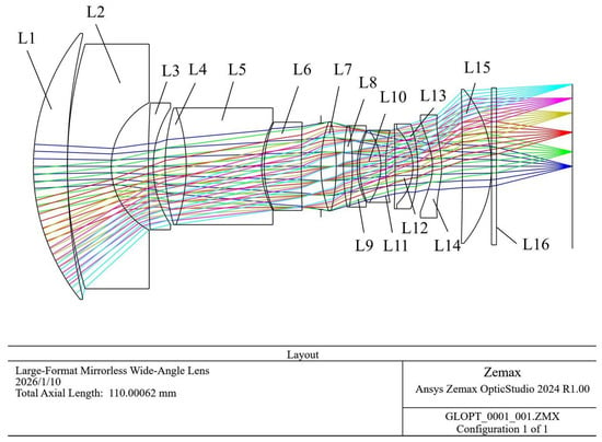
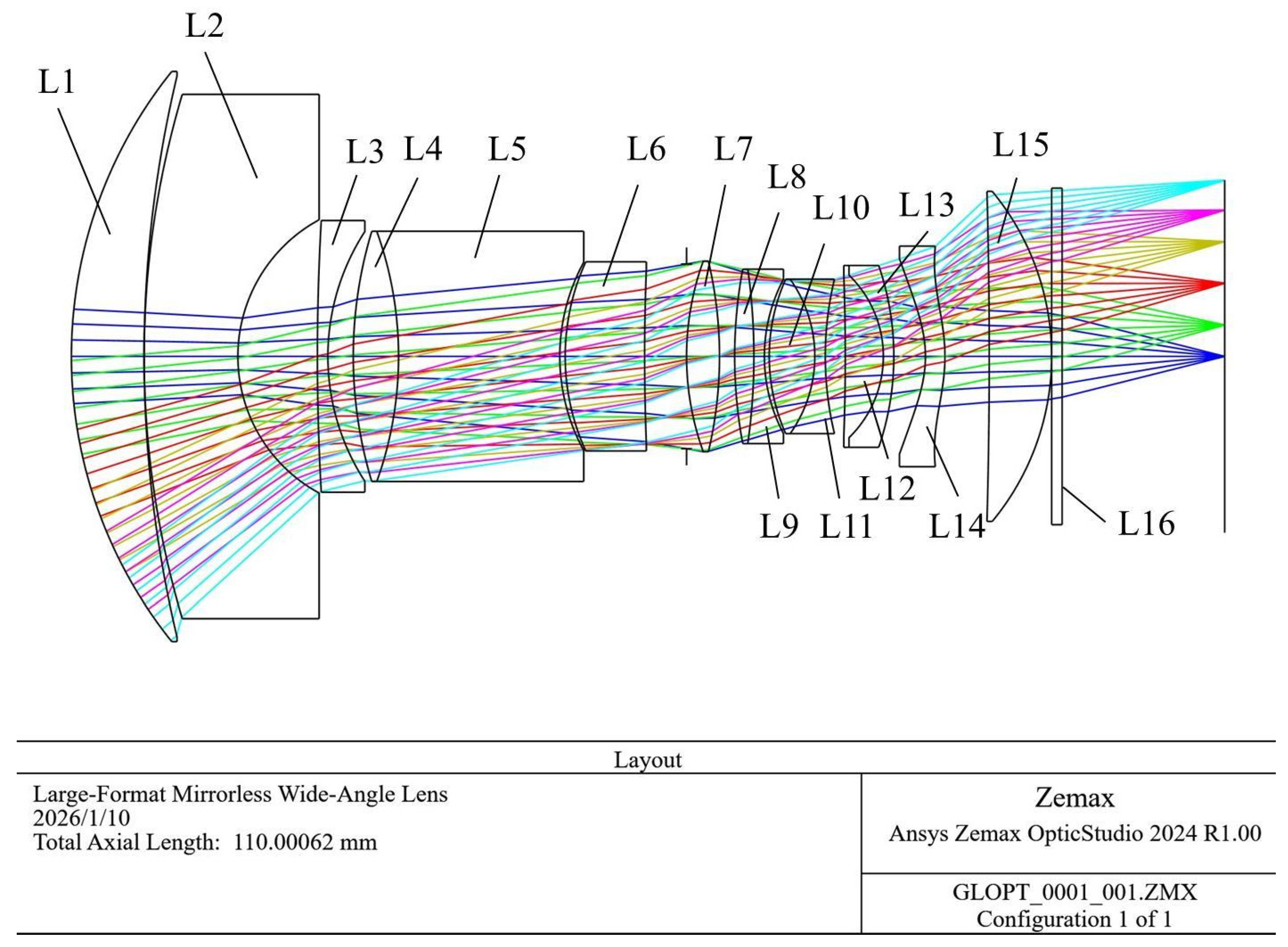
The final configuration comprises fifteen active lens elements (L1–L15) and one protective cover glass, incorporating four cemented doublets to effectively control chromatic aberrations. The detailed surface parameters (S1 to S30) are listed in Table 2. As illustrated in Figure 1, the front section preceding the aperture stop (S12) is designed to expand the field of view and correct primary aberrations. It begins with a strong negative meniscus lens (Lens 1, comprising surfaces S1 and S2, H-ZLAF75A) to bend high-incidence off-axis rays. This is followed by two positive lenses, Lens 2 (S3 and S4) and Lens 3 (S5 and S6), and a cemented doublet (Lens 4 and Lens 5, S7 to S9), which collectively act to balance the severe barrel distortion and coma introduced by Lens 1. An additional lens (Lens 6; S10 and S11) is placed just before the aperture stop (S12) to control the entrance pupil.
Table 2.
Optical system surface parameters. All glass materials listed in this table were sourced from CDGM Glass Co., Ltd. (Chengdu, China).
Figure 1.
Optimized optical layout of the large-format mirrorless wide-angle lens.
In the rear section, the optical power and color fringing are precisely managed by three consecutive cemented doublets: Lenses 8 and 9 (S15 to S17), Lenses 10 and 11 (S18 to S20), and Lenses 12 and 13 (S21 to S23). Element Lens 14 (S24 and S25) is a precision glass-molded asphere (D-ZLAF52LA; CDGM Glass Co., Ltd., Chengdu, China), which is critical for fine-tuning higher-order spherical aberrations and ensuring the chief ray angle (CRA) remains compatible with the sensor. Finally, Lens 15 (S26 and S27) functions as a field-flattener, followed by the sensor cover glass (S28 and S29), ensuring consistent sharpness across the entire image plane.
Table 3 lists the even-order aspheric coefficients (a2 to a6) for surfaces S24 and S25. Consistent with standard optical design conventions, the second-order term (a1) is set to zero, as its contribution is inherently included in the base curvature and conic constant. Thus, aspheric corrections begin with the fourth-order term (a2) and extend to higher even orders as needed to suppress residual aberrations. These coefficients provide essential degrees of freedom for controlling higher-order aberrations and achieving near-diffraction-limited performance.
Table 3.
Even-order aspheric coefficients (terms a2 through a6) for selected surfaces. These coefficients enable correction of higher-order aberrations such as spherical aberration, coma, and astigmatism. The a1 term (second order) is set to zero, as it is incorporated into the conic constant by convention.
3.2. MTF & Spot Diagrams
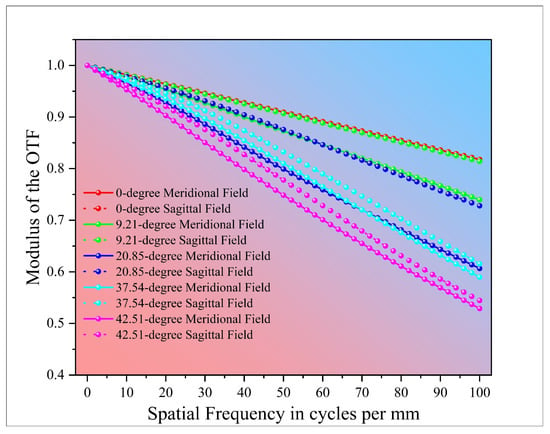
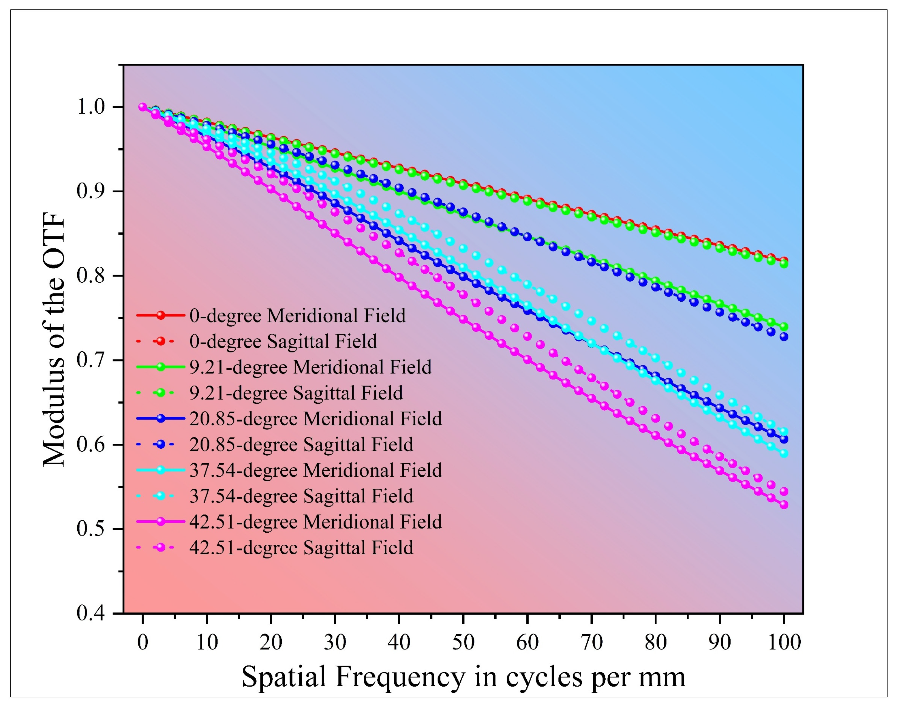
The modulation transfer function (MTF) shown in Figure 2 and the spot diagram results are jointly evaluated to characterize the imaging performance across the full field. At F/2.0, the on-axis MTF reaches approximately 0.98 at 10 lp/mm and 0.92 at 20 lp/mm, remaining as high as 0.85 at 40 lp/mm. At a half-field angle of 42.507° (corresponding to 0.8 field), the MTF at 40 lp/mm is approximately 0.70, while the extreme-field value decreases smoothly to about 0.62, satisfying the edge performance requirements. In addition, the on-axis MTF achieves 0.749 at a spatial frequency of 100 lp/mm, indicating strong high-frequency contrast capability. The small and uniform separation between sagittal and meridional curves across the field suggests effective control of astigmatism, with no evident MTF discontinuities indicative of residual coma or focus instability.
Figure 2.
MTF chart for the mirrorless camera imaging system.
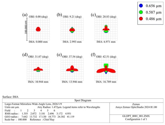
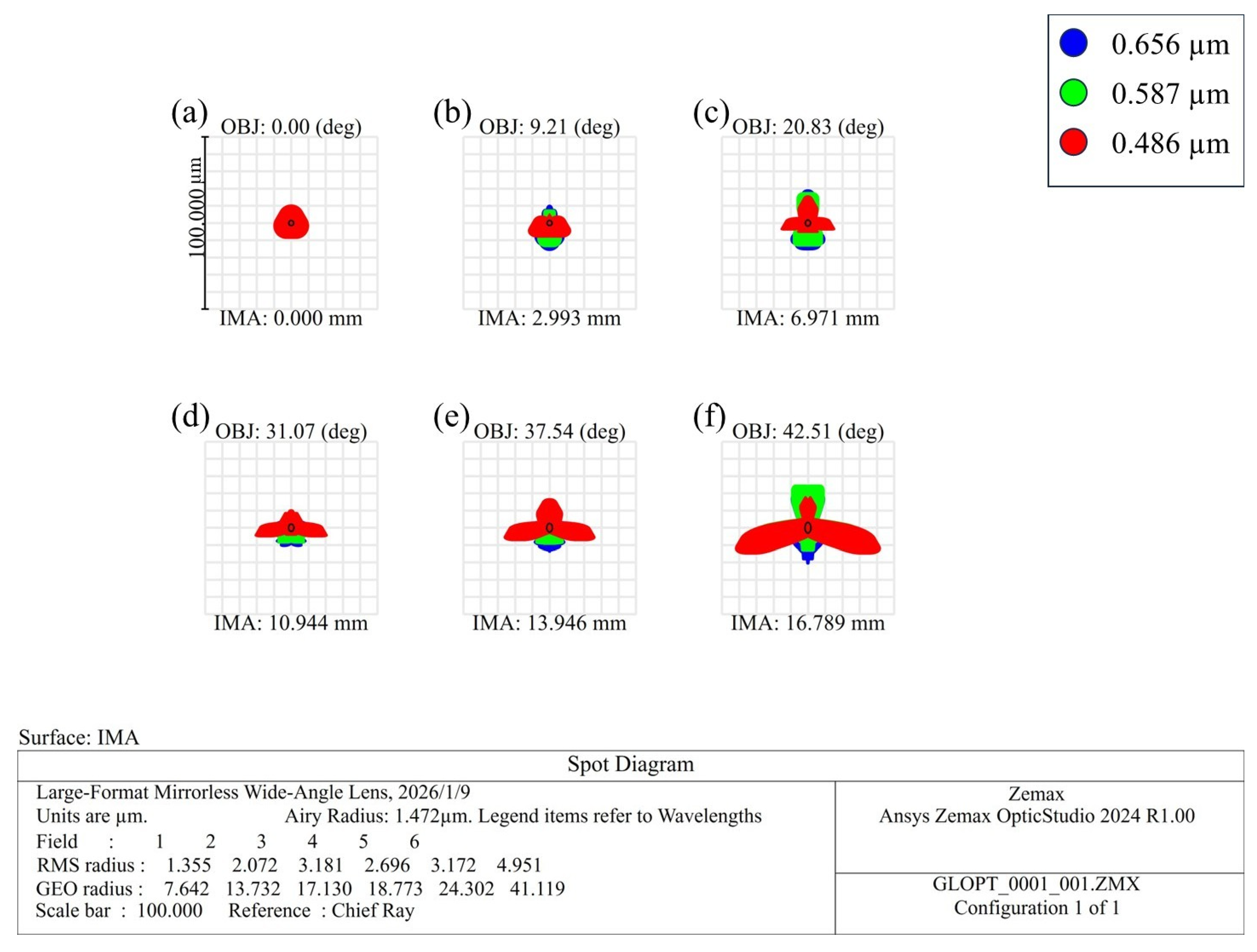
Spot diagrams further corroborate the frequency-domain performance discussed above. Figure 3 presents the polychromatic spot diagrams of the optimized 18 mm F/2.0 mirrorless wide-angle lens at six representative field positions, ranging from the on-axis point to the corner of the designed image format, with a maximum image height of 16.789 mm. Polychromatic rays at three design wavelengths (0.486 μm, 0.587 μm, and 0.656 μm) are traced, and the diffraction-limited Airy disk is overlaid for reference.
Figure 3.
Spot diagrams of the optimized 18.5 mm F/2.0 mirrorless wide-angle lens at six image heights corresponding to the designed image format: (a) on-axis (IMA = 0.000 mm); (b) IMA = 2.993 mm; (c) IMA = 6.971 mm; (d) IMA = 10.944 mm; (e) IMA = 13.946 mm; and (f) the extreme field corner (IMA = 16.789 mm). Polychromatic spots are shown for three design wavelengths, with the diffraction-limited Airy disk (radius: 1.472 µm) overlaid for reference.
At the on-axis field (IMA = 0 mm), the spot is highly compact and nearly circular, with the majority of rays well confined within the Airy disk. This behavior indicates the effective correction of primary spherical aberration and axial chromatic aberration at full aperture. The close overlap of the three wavelengths further confirms excellent longitudinal chromatic correction in the central field.
As the field height increases to intermediate positions (IMA ≈ 3–11 mm), the spot size increases gradually but remains tightly controlled. Specifically, the RMS spot radius grows from 1.355 µm on-axis to 2.072 µm at IMA = 2.993 mm and reaches 2.696 µm at IMA = 10.944 mm. The spots maintain a largely symmetric structure with only mild elongation, suggesting that coma and astigmatism are well balanced through appropriate optical power distribution and the use of aspheric surfaces. The polychromatic spots remain tightly clustered across the mid-field region, demonstrating effective suppression of lateral chromatic aberration.
Toward the extreme edge of the designed image field (IMA ≈ 14–16.8 mm), the spot diagrams exhibit moderate enlargement accompanied by mild fan-shaped or triangular patterns, which are characteristic of residual off-axis aberrations in fast retrofocus wide-angle systems. At the maximum field corner (IMA = 16.789 mm), the precise RMS radius is 4.951 µm. These edge-field values remain within a few times the Airy radius (1.472 µm), which is considered highly acceptable for an F/2.0 ultra-wide-angle lens. Importantly, the three wavelengths continue to overlap closely even at the extreme field, indicating well-controlled chromatic aberrations across the entire format.
Overall, the spot diagram results confirm near-diffraction-limited performance on-axis and diffraction-comparable spot sizes throughout the designed image field. The smooth and gradual increase in spot size toward the field edge is consistent with the observed MTF behavior. Specifically, the limited sagittal–tangential separation and the absence of abrupt contrast degradation at high spatial frequencies validate the effectiveness of the proposed optical design for high-resolution mirrorless wide-angle imaging within the specified image format.
3.3. Wavefront Performance Analysis
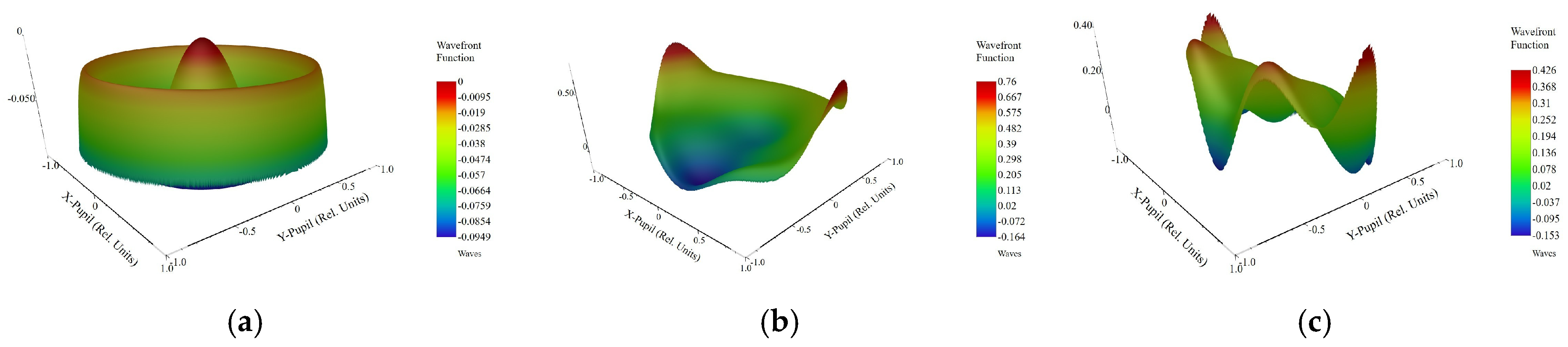
To further quantify the diffraction-limited capabilities and phase fidelity of the system, the wavefront performance was analyzed at three characteristic field positions: on-axis (0°), 0.7 field (31.07°), and the full field edge (42.51°). The reference wavelength is 0.587 μm.
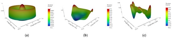
Figure 4 illustrates the wavefront phase maps. At the on-axis field, the system exhibits exceptional correction. The root mean square (RMS) wavefront error is merely 0.028 λ, which is significantly below the Maréchal diffraction limit (0.07 λ). The phase map is highly uniform (PV = 0.095 λ) with only negligible residual spherical aberration, confirming a sharp impulse response in the center.
Figure 4.
Wavefront phase maps across the field. The redundant text boxes are removed for clarity: (a) On-axis (0°), RMS = 0.028 λ. (b) 0.7 Field (31.07°), RMS = 0.179 λ. (c) Full-field edge (42.51°), RMS = 0.105 λ. The data demonstrates effective aberration control from center to edge.
Moving to the off-axis regions, the system demonstrates a trade-off typical of complex wide-angle designs. At the 0.7 field (31.07°), the wavefront exhibits asymmetric deformations indicative of residual coma, yielding an RMS value of 0.179 λ. However, performance recovers towards the extreme edge (42.51°), where the primary aberration shifts to astigmatism (saddle shape). The edge RMS is controlled at 0.105 λ, demonstrating that despite the broad viewing angle, the phase errors at the corners are kept within a reasonable range for high-resolution capture.
3.4. Field Curvature, Distortion, and Relative Illumination
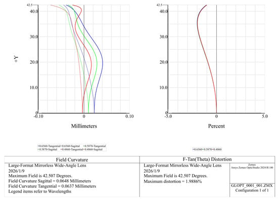
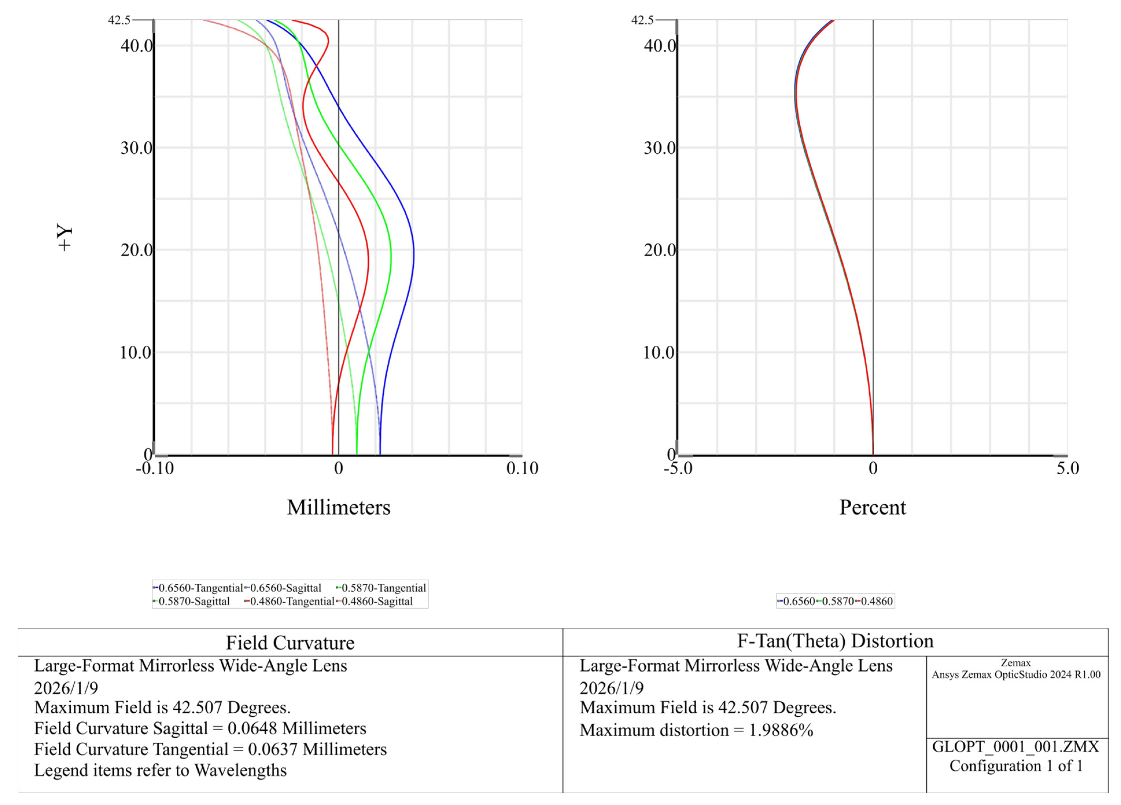
Field curvature is minimized by the rear field-flattener and appropriate power partitioning, producing closely spaced sagittal and tangential best-focus surfaces over the full designed field, as shown in Figure 5. The field curvature is plotted as a function of half-field angle (up to 42.5°), corresponding to a maximum image height of 16.789 mm. At the corner field, the separation between the sagittal and tangential best-focus positions remains very small, indicating effective suppression of residual astigmatism. The absolute best focus shift relative to the on-axis reference stays within the sub-0.1 mm range, which represents a modest field curvature for an 18.5 mm lens operating at F/2.0.
Figure 5.
Field curvature and distortion of the optimized 18.5 mm F/2.0 mirrorless wide-angle lens over the designed field. Left: Field curvature plot showing sagittal and tangential best-focus positions (in millimeters) as a function of half-field angle (+Y), evaluated at three wavelengths (0.4860 μm, 0.5870 μm, and 0.6560 μm). The maximum half-field angle is 42.5°, corresponding to a maximum image height of 16.789 mm. Right: F-tan(θ) distortion (percent) versus half-field angle for the same three wavelengths; the distortion is a monotonic barrel with a maximum value of 1.9886% at the field edge.
The distortion profile is a monotonic barrel without sign reversal. In the F-tan(θ) representation (Figure 5), the maximum distortion reaches approximately −2.0% at the field edge (42.5° half-field angle) and varies smoothly across the field. This well-behaved distortion characteristic is favorable for architectural scenes and renders any residual distortion straightforward to correct through digital post-processing.
Relative illumination follows a moderated fall-off governed by the cosine fourth law of illumination (). Through stop placement, controlled pupil vignetting, and a deliberate balance of distortion, corner illumination is raised to approximately 33% at full aperture, mitigating the severe edge darkening typically associated with fast ultra-wide-angle optics [4,5] and enabling more uniform exposure without mandatory stopping-down.
3.5. Full-Field Relative Illumination Analysis
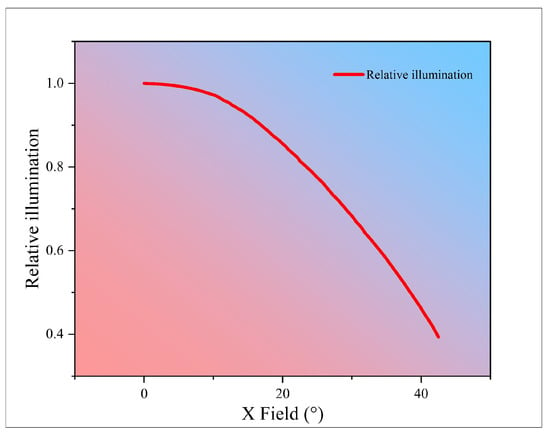
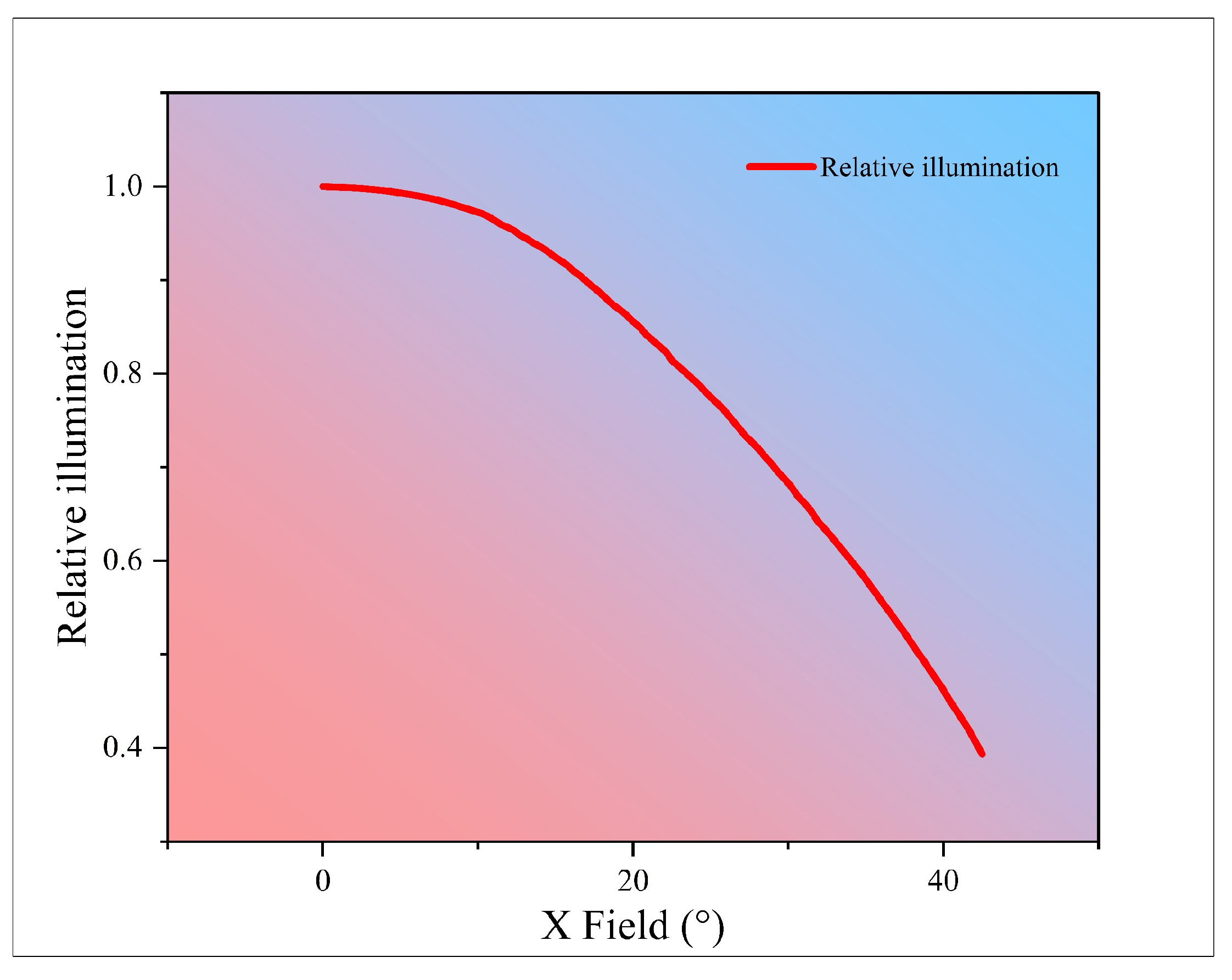
The relative illumination (REL) distribution of the proposed lens system is evaluated over the full image height under maximum aperture conditions. As shown in Figure 6, the on-axis illumination is normalized to unity, while the illumination gradually decreases toward the image periphery due to natural cosine falloff and residual vignetting effects. At the extreme corner of the full-frame image (image height of 21 mm, corresponding to a diagonal field angle of approximately 50°), the relative illumination remains above 30%, satisfying the specified system requirement. The smooth and monotonic behavior of the illumination curve indicates effective control of mechanical and optical vignetting through appropriate pupil placement and aperture-stop design. These results confirm that the proposed optical configuration achieves a good balance between wide-angle coverage, fast aperture, and acceptable edge illumination for practical full-frame mirrorless imaging applications.
Figure 6.
Relative illumination (vignetting) of the optimized 18.5 mm F/2.0 mirrorless wide-angle lens as a function of field angle in the X direction. The illumination is normalized to unity on-axis, showing a gradual falloff toward the edge of the field.
3.6. Tolerance & Manufacturability
3.6.1. MTF-Based Tolerance Analysis and Yield
To systematically evaluate the manufacturability of the proposed optical system, a stochastic Monte Carlo tolerance analysis was conducted using Zemax OpticStudio. The tolerance budget, detailing the assigned mechanical and optical fabrication limits, is summarized in Table 4. These values represent high precision yet achievable manufacturing standards compatible with modern production capabilities. Specifically, element thickness and radius of curvature tolerances are set to ±0.01 mm, while element tilt is controlled within 0.0167° (approximately 1 arcmin). Surface decenter is constrained to ±1.5 µm to strictly control coma aberrations, and surface irregularity follows a standard specification of 0.2 fringes (surface irregularity).
Table 4.
Assigned manufacturing and alignment tolerances used for the Monte Carlo tolerance analysis. Parameters include element thickness, curvature, tilt, surface irregularity, and material index variation. These tolerances reflect moderately relaxed production capabilities.
The reliability of the design was verified through 1000 independent Monte Carlo trials. To simulate the actual assembly and testing process, the back focal length was set as compensatory, allowing for minor axial adjustments of the image plane (e.g., via sensor shimming) to offset accumulated manufacturing errors.
The statistical results of the MTF performance are detailed in Table 5. The Monte Carlo simulation confirms a robust production yield under the defined tolerance conditions. Specifically, the median (50th percentile) of the assembled systems maintains a high resolution, with MTF values of 0.720 on-axis and 0.660 at the 0.7 field (31°). Furthermore, even under the influence of random error accumulation, the design demonstrates high stability: over 80% of the simulated samples satisfy the critical performance baseline, achieving MTF values exceeding 0.559 on-axis and 0.450 at the 0.7 field. These data indicate that the proposed lens system possesses a sufficient performance margin to withstand varying manufacturing conditions without requiring complex individual element alignment.
Table 5.
Statistical summary of the Monte Carlo simulation (1000 trials) showing the cumulative probability of MTF performance. Note: The reported MTF values are polychromatic, evaluated at a spatial frequency of 40 lp/mm. The wavelength weighting applied is 1:2:1 for 0.486 μm, 0.587 μm, and 0.656 μm, respectively.
3.6.2. Wavefront Error Distribution and Manufacturability
In addition to MTF, the manufacturing yield was evaluated using RMS Wavefront Error (at λ = 0.587 μm) as a global performance metric. A Monte Carlo simulation of 1000 trials was conducted to assess the statistical distribution of wavefront aberrations under the assigned tolerance budget.
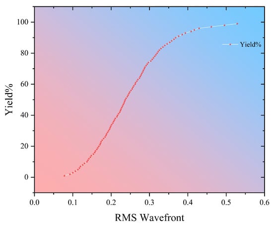
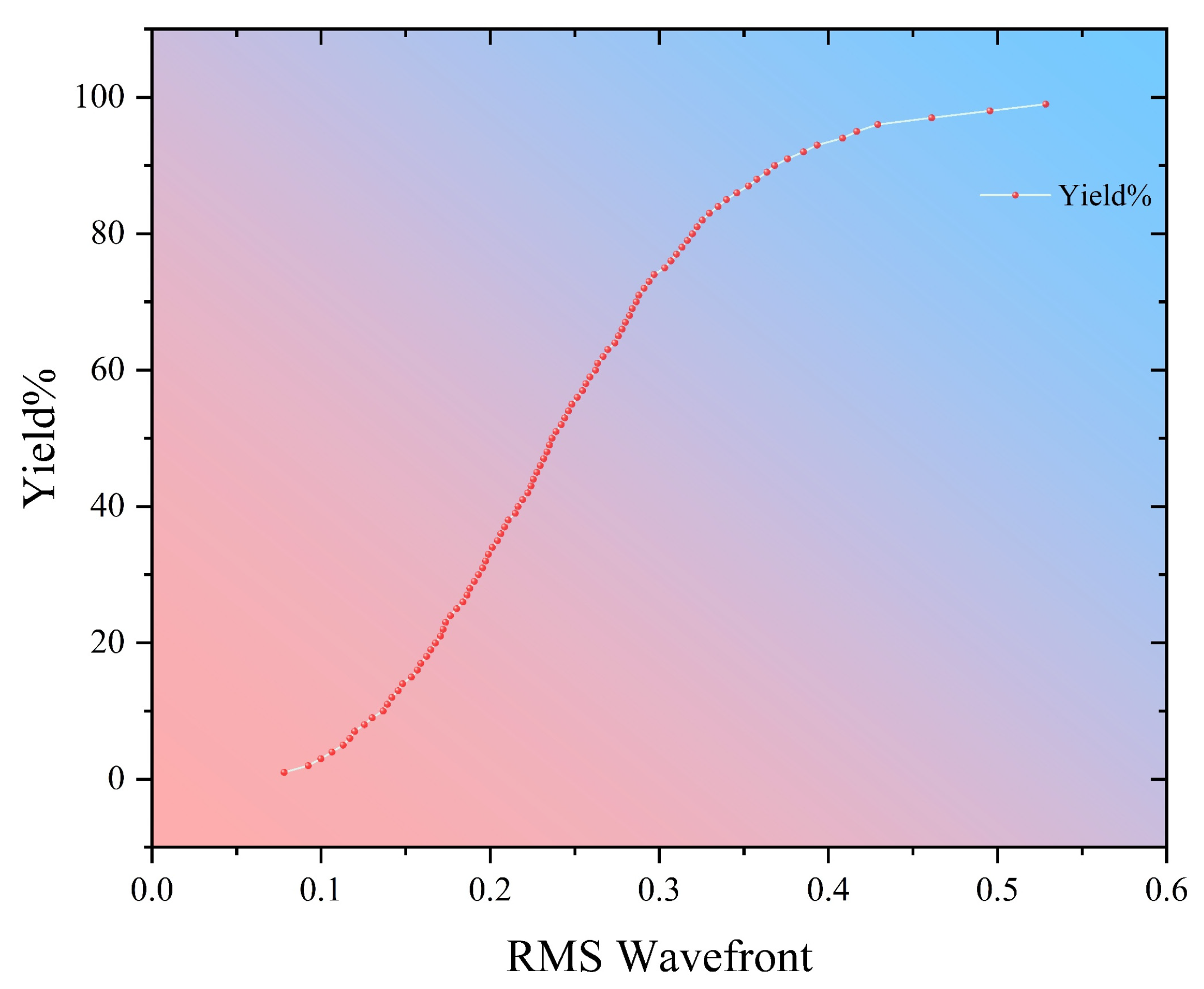
Figure 7 presents the cumulative yield curve (“Fast Yield”). The statistics indicate a robust production distribution: the median (50th percentile) of the assembled systems exhibits an RMS wavefront error of approximately 0.198 λ, while 95% of the population remains within an error of 0.332 λ.
Figure 7.
Cumulative probability distribution of the RMS wavefront error obtained from 1000 Monte Carlo simulation trials. The median value (50% yield) is approximately 0.198 λ at the reference wavelength of 0.587 µm, indicating stable optical performance under tolerance conditions.
These results demonstrate that the cumulative impact of fabrication and assembly errors is well-contained. Although the system is not strictly diffraction-limited (which is typical for high-speed wide-angle photographic objectives), the wavefront error levels are consistent with commercial-grade imaging performance, confirming that the tolerance allocation is practical for mass production.
Although the system is not strictly diffraction-limited (which is typical for high-speed wide-angle photographic objectives), the optical performance remains highly competitive. For high-resolution large-format mirrorless cameras, an RMS wavefront error below 0.25 λ is generally considered highly acceptable for achieving sharp contrast and excellent imaging quality across the field. Given that the median (50th percentile) of our simulated systems achieves an RMS error of approximately 0.198 λ, the design reliably meets commercial-grade imaging requirements. These results confirm that the assigned tolerance allocation is highly practical for mass production.
4. Discussion
The development of high-speed wide-angle optics for mirrorless systems presents a fundamental engineering conflict between the short back focal length requirement and the necessity for high-resolution aberration correction. Our proposed 18.5 mm F/2.0 lens successfully resolves this by employing a modified retrofocus architecture combined with strategic glass-molded aspherical surfaces.
From the perspective of practical application, this design addresses several critical limitations found in conventional wide-angle lenses. Unlike traditional fast ultra-wide designs that often suffer from severe edge darkening or complex distortion profiles, our system maintains an edge relative illumination of 33% and restrains distortion to a smooth, correctable 2-barrel profile. Crucially, by integrating an internal floating-focus mechanism, the system strictly suppresses focus breathing to under 1%. This is a vital feature for modern hybrid video-photo imaging, ensuring consistent framing during dynamic focus pulls—a metric frequently overlooked in traditional photographic lens designs.
To further contextualize the engineering value of this study, Table 6 presents a comparison between the proposed design and the typical specifications of commercially available large-format mirrorless wide-angle lenses (e.g., 18 mm or 20 mm prime lenses with F/1.8 to F/2.8 apertures). While modern commercial lenses often rely heavily on digital in-camera profiles to correct distortion and focus breathing, our proposed design achieves exceptional control over these parameters purely through optical hardware. Specifically, the internal floating-focus architecture suppresses the breathing ratio to under 1%, a metric that is critical for professional cinematography but often compromised in photography-centric commercial lenses. Furthermore, the passive athermalization strategy ensures stable resolving power from to , exceeding the typical environmental operating limits of standard consumer optics.
Table 6.
Comparison of key optical parameters between the proposed design and typical commercially available large-format mirrorless wide-angle lenses.
Furthermore, the theoretical excellence of an optical design must be balanced against its physical reliability and manufacturability. Through passive athermalization strategies, optical thermal drift is physically compensated by the mechanical expansion of the housing (as mathematically established in Equation (3)). This compensation mechanism was rigorously verified through multi-configuration thermal modeling in Zemax OpticStudio, which provided clear simulation evidence that the system maintains stable MTF performance across an extreme temperature range of −30 °C to +70 °C without requiring active mechanical refocusing.
While this study establishes a highly manufacturable and athermalized solution, future research could push the boundaries of miniaturization even further. Exploring advanced optical elements, such as freeform optics or meta-surfaces, could provide greater degrees of freedom to further optimize the trade-off between the physical envelope and ultra-wide-angle performance.
5. Conclusions
In conclusion, we have successfully designed and validated a compact 18.5 mm F/2.0 wide-angle lens tailored for large-format mirrorless cameras. By employing a modified retrofocus architecture with aspherical elements and an internal floating-focus mechanism, the system achieves exceptional optical performance while effectively resolving the inherent flange-distance constraints.
The main conclusions of this study are as follows:
- High-Resolution Imaging: The system delivers excellent resolving power for high-pixel-density sensors, maintaining a Modulation Transfer Function (MTF) greater than 0.5 even at a high spatial frequency of 100 lp/mm.
- Strict Aberration Control: Optical distortion is precisely controlled within −1.3%, relative illumination is preserved above 33%, and the chief ray angle is constrained below 18°. Focus breathing is minimized to less than 1%.
- High Manufacturability and Stability: The design is athermally stable across a wide temperature range, and comprehensive Monte Carlo tolerance analysis confirms a mass-production yield exceeding 80% under standard industrial error conditions.
Ultimately, this study provides a theoretically robust, athermally stable, and practically feasible optical solution, serving as a valuable engineering reference for the development of next-generation high-resolution mirrorless imaging systems.
Author Contributions
Conceptualization, W.X.; methodology, W.X.; investigation, W.X. and Q.Z.; resources, D.L.; data curation, W.X. and Y.Z.; writing—original draft preparation, W.X.; writing—review and editing, D.L., C.W., P.S., S.L. and J.W. and Q.Z.; supervision, D.L. All authors have read and agreed to the published version of the manuscript.
Funding
This study was conducted with support from the Shaanxi Provincial Natural Science Foundation (Grant No. 2023JCYB047), the Xi’an Science Technology Bureau (Grant Nos. 23GXFW0003 and WeiYang202308), and the Education Department of Shaanxi Province (Grant Nos. 20JK0538 and 25JK0365).
Institutional Review Board Statement
Not applicable.
Informed Consent Statement
Not applicable.
Data Availability Statement
The original contributions presented in this study are included in the article. Further inquiries can be directed to the corresponding author.
Conflicts of Interest
The authors declare that the research was conducted in the absence of any commercial or financial relationships that could be construed as a potential conflict of interest.
Abbreviations
The following abbreviations are used in this manuscript:
| ASA | Aberration sensitivity analysis |
| BFL | Back focal length |
| CRA | Chief ray angle |
| MTF | Modulation transfer function |
| OTF | Optical transfer function |
| REL | Relative illumination |
| RMS | Root mean square |
References
- Ben, C.; Shen, H.; Yu, X.; Meng, L.; Cheng, H.; Jia, P. Stray Light Analysis and Suppression for an Infrared Fourier Imaging Spectrometer. Photonics 2024, 11, 173. [Google Scholar] [CrossRef] [Scilit]
- Cheng, D.; Wang, D.; Yao, C.; Liu, Y.; Dai, X.; Wang, Y. Thin and Large Depth-of-Field Compound-Eye Imaging for Close-Up Photography. Photonics 2024, 11, 107. [Google Scholar] [CrossRef] [Scilit]
- Chitra, P.; Dudy, N.K.; Verma, S.; Mishra, G. A Comparative Analysis of DSLR and Mirrorless Cameras for Dental Photography. J. Indian Orthod. Soc. 2024, 58, 158–164. [Google Scholar] [CrossRef] [Scilit]
- Dube, B.; Cicala, R.; Closz, A.; Rolland, J.P. How good is your lens? Assessing performance with MTF full-field displays. Appl. Opt. 2017, 56, 5661–5667. [Google Scholar] [CrossRef] [Scilit]
- Engelberg, J.; Levy, U. Standardizing flat lens characterization. Nat. Photonics 2022, 16, 171–173. [Google Scholar] [CrossRef] [Scilit]
- Gowda, B.N.V.K.; Gauni, S.; Gurushankar, K.; Maik, V. Application in optical design: Optimization for high intensity and aberration free camera lens system. Optik 2022, 262, 168764. [Google Scholar] [CrossRef] [Scilit]
- Jiang, R.; Shi, D.; Wang, Y. Long-range fourier ptychographic imaging of the object in multidimensional motion. Opt. Commun. 2025, 575, 131307. [Google Scholar] [CrossRef] [Scilit]
- Kim, Y.; Choi, T.; Lee, G.Y.; Kim, C.; Bang, J.; Jang, J.; Jeong, Y.; Lee, B. Meta surface folded lens system for ultrathin cameras. Sci. Adv. 2024, 10, adr2319. [Google Scholar] [CrossRef] [Scilit]
- Pan, N.; Gao, S.; Bai, J.; Wang, K. Design of a dual-channel panoramic annular lens for imaging and time-of-flight based on freeform surface prisms. Opt. Express 2025, 33, 29377–29394. [Google Scholar] [CrossRef] [Scilit]
- Li, H.; Chen, H.; Li, X.; Song, H.; Wang, D. Structural optical design of multi-group, high zoom ratio optical systems. Opt. Commun. 2024, 551, 130022. [Google Scholar] [CrossRef] [Scilit]
- Pinilla, S.; Fröch, J.E.; Rostami, S.R.M.; Katkovnik, V.; Shevkunov, I.; Majumdar, A.; Egiazarian, K. Miniature color camera via flat hybrid meta-optics. Sci. Adv. 2023, 9, eadg7297. [Google Scholar] [CrossRef] [Scilit] [PubMed]
- Li, Y.; Li, X.; Sun, J.; Li, J.; Zhang, Z.; Wang, Z.; Liu, F. Design of inverse remote optical system based on aspherical surface. In Proceedings of the International Conference on Precision Instruments and Optical Engineering (PIOE 2023), Shanghai, China, 25–27 August 2023; Tao, W., Pan, H., Yao, B., Eds.; SPIE: Bellingham, WA, USA, 2023; Volume 12976, pp. 231–237. [Google Scholar] [CrossRef] [Scilit]
- Liu, X.-N.; Fu, J.-Y.; Liu, S.-B.; Zhang, Z.-Y.; Li, Y.-Y.; Xie, N.; Li, Y.-H.; Li, L. Reflective zoom lens based on liquid metal. Opt. Commun. 2024, 550, 129995. [Google Scholar] [CrossRef] [Scilit]
- Fan, C.; Yang, B.; Liu, Y.; Gu, P.; Wang, X.; Zong, H. Zoom lens with high zoom ratio design based on Gaussian bracket and particle swarm optimization. Appl. Opt. 2021, 60, 3217–3223. [Google Scholar] [CrossRef] [Scilit] [PubMed]
- Siraji, A.A.; Zhao, Y. Design and analysis of thin optical lens composed of low-index subwavelength structures. Appl. Opt. 2019, 58, 4654–4664. [Google Scholar] [CrossRef] [Scilit]
- Liu, Z.; Gan, Z.; Zhang, M.; Lv, J.; Xing, K.; Hong, H. Design of a small non-displacement zoom optical system based on Gaussian brackets and traversal ideation. Opt. Commun. 2024, 557, 130336. [Google Scholar] [CrossRef] [Scilit]
- Mahan, J.R.; Vinh, N.Q.; Ho, V.X.; Munir, N.B. Monte Carlo ray-trace diffraction based on the Huygens–Fresnel principle. Appl. Opt. 2018, 57, D56–D62. [Google Scholar] [CrossRef] [Scilit]
- Park, J.; Choi, Y.; Kwon, S.; Lee, Y.; Kim, J.; Kim, J.-J.; Lee, J.; Ahn, J.; Kwak, H.; Yang, Y.; et al. Microsphere-assisted hyperspectral imaging: Super-resolution, non-destructive metrology for semiconductor devices. Light Sci. Appl. 2024, 13, 122. [Google Scholar] [CrossRef] [Scilit]
- Sun, W.-S.; Liu, Y.-H.; Tien, C.-L. Optical Design of a Miniaturized 10× Periscope Zoom Lens for Smartphones. Micromachines 2023, 14, 1272. [Google Scholar] [CrossRef] [Scilit]
- Usukura, N.; Yoshida, T.; Minoura, K.; Honma, Y. Novel high light efficiency pancake optics for HMD named “double path”. Opt. Rev. 2024, 31, 607–613. [Google Scholar] [CrossRef] [Scilit]
- Jipeng, Z.; Guangwei, S.; Yuqi, H.; Shangnan, Z.; Mingxin, L.; Xin, Z. Optimization of optical system for reducing tolerance sensitivity based on the high-order nodal aberration theory. Opt. Express 2024, 32, 14334–14355. [Google Scholar] [CrossRef] [Scilit]
- Choi, H.; Ryu, J. Design of Wide Angle and Large Aperture Optical System with Inner Focus for Compact System Camera Applications. Appl. Sci. 2020, 10, 179. [Google Scholar] [CrossRef] [Scilit]
- Gu, P.; Chen, J.; Huang, W.; Shi, Z.; Zhang, X.; Zhu, L. Evaluation of surface quality and error compensation for optical aspherical surface grinding. J. Mater. Process. Technol. 2024, 327, 118363. [Google Scholar] [CrossRef] [Scilit]
- Li, K.; Chen, X.; Bian, Y.; Xing, Y.; Li, X.; Liu, D.; Liu, Y. Design and optical analysis of a refractive aspheric intraocular lens with extended depth of focus. Optics 2023, 4, 146–155. [Google Scholar] [CrossRef] [Scilit]

Disclaimer/Publisher’s Note: The statements, opinions and data contained in all publications are solely those of the individual author(s) and contributor(s) and not of MDPI and/or the editor(s). MDPI and/or the editor(s) disclaim responsibility for any injury to people or property resulting from any ideas, methods, instructions or products referred to in the content. |
© 2026 by the authors. Licensee MDPI, Basel, Switzerland. This article is an open access article distributed under the terms and conditions of the Creative Commons Attribution (CC BY) license.