


Abstract
This paper proposes a Hybrid-Field DD (HFDD) coupler designed for wireless power transfer (WPT) in mobile robots within smart manufacturing environments, utilizing a dual-coupling mechanism of magnetic and electric fields. The proposed coupler integrates Double-D coils for vertical magnetic field concentration with a split metal plate structure for enhanced electric field coupling in a compact, low-profile design. To evaluate the electromagnetic performance and the impact of inevitable eddy current interference, two distinct configurations—Front Plate Arrangement (FPA) and Back Plate Arrangement (BPA)—are analyzed through both theoretical modeling and 3D full-wave simulations (HFSSs). The comparative results demonstrate that the FPA model reduces the peak induced current intensity by 56.23 A/m compared to the BPA and achieves a peak leakage magnetic field intensity of 1.12 A/m, which is 28% lower than the 1.56 A/m observed in the BPA, offering a superior solution for suppressing leakage magnetic field and contributing to robust coupling stability. The high consistency between the proposed analytical methodology and numerical simulations underscores the theoretical robustness of the HFDD structure, establishing a clear design framework for efficient power transfer in robotic applications.
1. Introduction
With the rapid expansion of Industry 4.0 and smart manufacturing, industrial mobile robots such as Autonomous Guided Vehicles (AGVs) and Autonomous Mobile Robots (AMRs) have become essential components for ensuring process flexibility and autonomy [1,2,3]. For these robots to maintain 24/7 continuous operation, efficient energy supply infrastructure is crucial. Traditional wired or contact-based charging systems face significant challenges, including mechanical wear, the risk of sparking (arcing) in hazardous environments, and increased maintenance costs due to physical connector degradation [4]. Consequently, wireless power transfer (WPT) technology has emerged as a key infrastructure for the energy independence of mobile robots, offering enhanced reliability and safety in harsh industrial environments [5].
Inductive wireless Power Transfer (IPT) using magnetic field coupling is currently the most widely adopted WPT technology due to its high power density. However, when applied to mobile robots, IPT encounters physical limitations related to the metallic chassis, typically made of steel or aluminum. The strong time-varying magnetic fields induce eddy currents within the metallic chassis, leading to significant Joule heating and a drastic reduction in transmission efficiency [6,7]. While heavy ferrite cores and aluminum shielding are commonly used to mitigate these effects, they increase the overall weight of the robot, thereby reducing its payload capacity and operational efficiency [6,8].
Capacitive wireless Power Transfer (CPT), which utilizes electric field coupling, has been proposed as a lightweight alternative that is relatively immune to eddy current losses [9,10]. Since electric fields do not penetrate deeply into metallic bodies, CPT can significantly reduce the weight of the coupler. However, the low permittivity of the air medium results in a very small coupling capacitance, necessitating extremely high frequencies or high voltages to transfer substantial power [10,11]. These requirements can lead to dielectric breakdown of the air and increased switching losses in power conversion stages, limiting the application of standalone CPT systems to short-range, low-power scenarios [12].
To satisfy the requirements for high power, lightweight design, and misalignment tolerance simultaneously, hybrid field coupling wireless power transfer (HWPT) that integrate both IPT and CPT paths have gained attention [13,14,15,16]. In these systems, the electromagnetic fields work complementarily; for instance, the CPT plates can act as an active shield to disperse the leakage magnetic field while providing an auxiliary power path during misalignment [17]. Such integrated structures have the potential to reduce the total weight of the charging system by 20% to 30% while maintaining high energy reliability [6].
The Double-D (DD) coil has been extensively researched as a prominent inductive coupling structure for HWPT, as it provides enhanced magnetic flux path efficiency and superior tolerance to lateral misalignment in comparison to conventional unipolar designs [18,19,20,21]. Furthermore, the implementation of split capacitive plates allows for the utilization of fringing electric fields at the edges to increase effective capacitance without increasing the physical thickness of the coupler [17]. Despite these advantages, the vertical positioning of the plates relative to the coils remains a complex optimization problem, as it directly affects coupling strength, eddy current losses, and the overall electromagnetic transparency of the system [11,22].
In this paper, we propose a HWPT coupler structure integrating DD coils and split capacitive plates, specifically characterized by its ability to suppress leakage magnetic field through optimized plate positioning. This study provides a comprehensive numerical evaluation of electromagnetic coupling characteristics and eddy current distributions, establishing the fundamental rationale for hybrid-field DD coupler optimization. Through theoretical modeling and 3D full-wave simulations, we analyze the fundamental coupling mechanisms and parasitic losses inherent in the integrated hybrid structure. The accuracy of the proposed analytical framework is verified by comparing the numerical simulation results with theoretical predictions. By demonstrating a distinctive coupler structure optimized for low electromagnetic interference, this study is expected to contribute to the advancement of safe and efficient wireless power transfer technology in intelligent production environments.
2. Theoretical Analysis and Design of the Hybrid-Field DD Coupler
2.1. Configuration of the Hybrid-Field DD Coupler
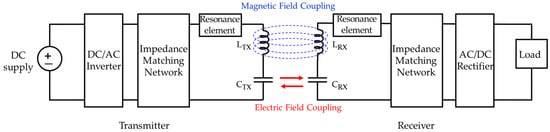
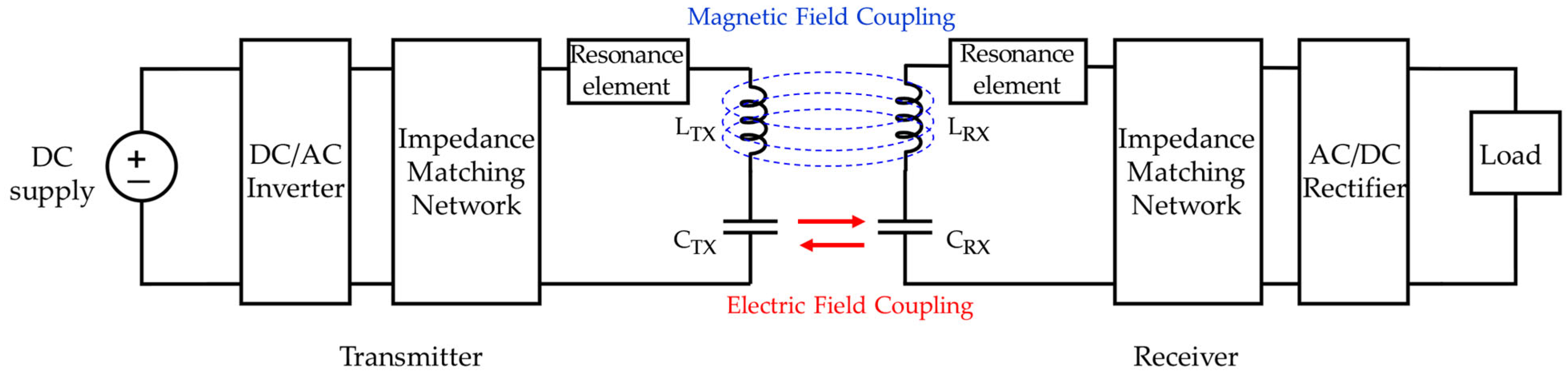
The coupler proposed in this paper features a HWPT that simultaneously utilizes both magnetic and electric field coupling, as illustrated in Figure 1. This Hybrid-Field DD (HFDD) coupler consists of DD coils for magnetic field generation and four split metal plates for electric field generation. A DC supply is converted into an AC voltage at the transmitter and passes through an impedance matching network. The AC voltage source induces magnetic field coupling between the two coils and electric field coupling between the four plates. To maximize coupling at the desired operating frequency, the impedance matching networks for both the transmitter and receiver must be precisely designed. This involves matching the source and load impedances to minimize reflected power and ensure high power transfer efficiency. Therefore, a vector network analysis of the coupler, including the impedance matching networks, must be prioritized.
Figure 1.
Configuration of the HWPT system.
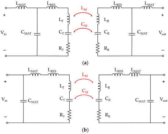
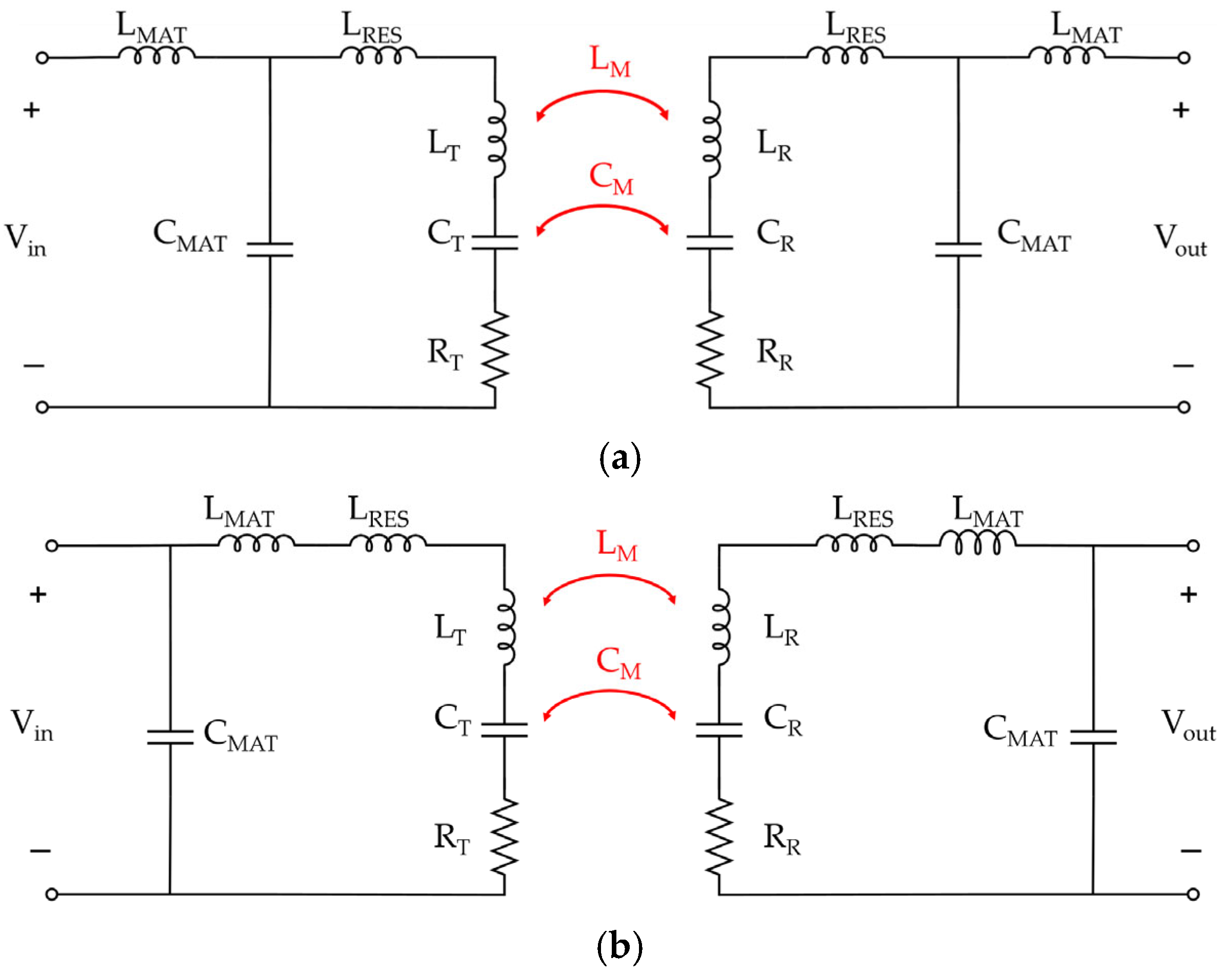
The equivalent circuits of the HFDD coupler for the FPA and BPA configurations are illustrated in Figure 2a and Figure 2b, respectively. This topological difference in the equivalent circuits arises because the intrinsic input impedance varies significantly depending on the relative positioning of the capacitive plates.
Figure 2.
Equivalent circuits of the HFDD coupler. (a) FPA; (b) BPA.
As previously described, mutual inductance (LM) is formed by the magnetic field coupling between the two coils, while mutual capacitance (CM) is generated by the electric field coupling between the four plates. The definitions of each parameter constituting the equivalent circuit are summarized in Table 1.
Table 1.
Parameters of the equivalent circuit model for the HFDD coupler.
The parameter values summarized in Table 1 were derived through 3D full-wave analysis using ANSYS HFSS 2021R2. Here, the abbreviations FPA (Front Plate Arrangement) and BPA (Back Plate Arrangement) refer to the two comparative models based on the plate positioning, which will be discussed in detail in Section 3. Self-inductance and self-capacitance refer to the intrinsic properties of the coupler before the integration of resonance and impedance matching elements. The intrinsic LC parameters of the coupler were initially calculated based on a standalone transmitter; however, these values vary upon the integration of the receiver. Furthermore, impedance matching was performed under a resonant condition at a transfer distance of 140 mm. The reference input impedances at this distance were determined as for the FPA and for the BPA.
2.2. Theoretical Considerations of Hybrid Coupling Characteristics and Eddy Current Losses
In smart manufacturing environments, WPT systems for mobile robots require not only high power transfer efficiency but also effective suppression of leakage magnetic field to minimize interference with surrounding precision equipment. The HFDD coupler proposed in this study achieves high energy density by simultaneously utilizing both magnetic and electric field coupling. Furthermore, it allows for the shielding of electromagnetic fields or the control of coupling characteristics depending on the arrangement of the metal plates. In this section, a theoretical model for the coupling coefficients and eddy current distribution is derived to quantitatively analyze the performance differences between the FPA and BPA models.
2.2.1. Definition of Coupling Coefficients
In the proposed structure, electromagnetic coupling is characterized by the simultaneous contribution of magnetic flux linkage and electric displacement. First, the magnetic field coupling coefficient () and the electric field coupling coefficient () are defined as Equations (1) and (2), respectively:
Furthermore, the overall coupling coefficient () is defined by the splitting of the resonance frequencies in a symmetric pair of resonators. By applying the bisection theorem to the symmetrical coupler, the system can be decomposed into even-mode and odd-mode circuits. For the even-mode () excitation, where the symmetry plane acts as a magnetic wall, and the odd-mode () excitation, where it acts as an electric wall, the respective resonance frequencies are given as Equation (3):
where and represent the self-inductance and effective self-capacitance including the plate contributions. By substituting these modal frequencies into the fundamental definition of the coupling coefficient, , the total hybrid coupling is derived as Equation (4):
These equations serve as key indicators that determine the overall transfer capacity and efficiency of the system.
2.2.2. Modeling of Eddy Current Density and Current Distribution
In a structure where the DD coil and metal plates are adjacent, eddy currents are generated on the plate surface by Faraday’s law of induction. This acts as a major source of loss that reduces system efficiency and simultaneously interferes with the magnetic field formation of the DD coil. The relationship between the induced electromotive force and the eddy current density () is expressed in Equations (5) and (6):
Here, the peak magnetic flux density () generated by the DD coil and the resulting maximum eddy current density () are calculated as Equations (7) and (8) based on the number of coil turns (), current (), separation distance (), and plate width () as follows:
Finally, the total current density () formed on the plate surface can be modeled as Equation (10), which is the sum of the base current () from Equation (9) and the eddy current component induced by the DD coil:
In Equations (9) and (10), specific parameters are utilized to characterize the physical behavior of the current density distribution. The term denotes the current density at the geometric center of the plate, which is determined by the total applied RMS current and the plate’s physical dimensions to establish the baseline magnitude of the distribution. The geometric factor serves as the exponent defining the edge singularity caused by the finite thickness of the conductive plate; in this study, a value of 0.6 was selected as the optimal value to accurately represent the current concentration at the plate boundaries. Similarly, the proximity effect coefficient accounts for the electromagnetic interaction between adjacent couplers, with a value of 0.1 assigned to characterize the resulting asymmetrical distribution. Furthermore, while the exponential order governs the spatial gradient of the induced current, a sinusoidal function was used in this numerical implementation instead. This approach was specifically selected to emulate the characteristic spatial profile of eddy currents-marked by a zero-crossing at the center and peak magnitudes at the edges-ensuring high fidelity and consistency with the simulation results.
Through this theoretical analysis, the magnitude of the eddy current and the magnetic field cancelation effect in the FPA and BPA structures can be predicted. This model is compared with the HFSS simulation results in Section 3 to verify the validity of the proposed coupler. Furthermore, it serves as a reference to characterize the two models compared to the theoretical values. MATLAB 2024B was used for the theoretical calculations.
3. 3D Full-Wave Analysis Methodology and Model
This section provides a detailed description of the design model developed using ANSYS HFSS 2021R2 and outlines the methodology for evaluating its electromagnetic characteristics. We define the key performance metrics of the coupler, such as transmission coefficients (S-parameters), electromagnetic field distributions, and current density profiles. A comparative analysis is performed to predict which of the two proposed models provides more favorable conditions for efficient power transfer. According to previous literature, high-fidelity 3D full-wave simulations have been shown to yield results that align closely with experimental measurements [23]. Therefore, the proposed designs in this study are evaluated based on high-fidelity 3D full-wave simulations to verify the structural rationale and coupling mechanisms.
3.1. Design Concept and Structural Rationale of the HFDD Coupler
HWPT can integrate various types of coils and plates. Several designs have been proposed in previous studies, such as a low-profile structure combining a planar spiral coil with ring-shaped metal plates [24], and a lightweight system that forms both magnetic and electric fields simultaneously by bending metal strips into specific shapes without separate windings [25]. Additionally, hybrid magnetic coupling structures mixing solenoid and planar coils have been researched to overcome misalignment issues in underwater environments [26]. However, these existing structures often exhibit a high dependency on magnetic field coupling or face challenges in the independent control of parameters. Consequently, they possess inherent limitations regarding stable power transfer under wide-ranging misalignment or rotation scenarios, as well as in the optimization of compact, low-profile designs.
However, to design an HWPT that is both low-profile and compact, sufficient spacing cannot be maintained between the coils and the plates. This limitation inevitably leads to electromagnetic interference between the components. To secure sufficient coupling characteristics for both magnetic and electric fields while maintaining a compact form factor, this study proposes a structure that integrates DD coils with a split plate configuration. The DD coil is excellent for focusing the magnetic field vertically [27,28], and the split plate structure offers a relative advantage in forming mutual capacitance compared to conventional stacked structures. Furthermore, from a structural perspective, this arrangement allows the plates to be compactly positioned within the internal space of the DD coil, facilitating an integrated and efficient design.
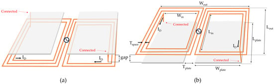
In this study, two models are distinguished and compared based on the plate arrangement, as shown in Figure 3. The transmitter and receiver are positioned facing each other in inverted structures. While maintaining a constant gap between the Tx and Rx DD coils, the models are categorized according to whether the plates are placed closer to or further from the opposite unit. The FPA refers to a structure where the plates are positioned closer to each other than the DD coils between the transmitter and receiver. Conversely, the BPA refers to a structure where the plates are positioned further behind the DD coils. Such configurations inevitably generate strong eddy currents on the plates, leading to losses. Therefore, it is crucial to minimize these eddy currents to prevent them from interfering with the magnetic field focusing of the DD coils.
Figure 3.
Structural illustrations of the transmitter units for conceptual understanding: (a) Front Plate Arrangement (FPA); (b) Back Plate Arrangement (BPA).
For the FPA, it can be predicted that electric field coupling will be dominant due to the proximity of the plates. However, it may also be significantly affected by eddy currents induced by the concentrated magnetic field of the DD coils. Since these eddy currents can hinder the formation of electric fields on the plates, the FPA might ultimately suffer from a reduction in both electric and magnetic field strengths. In contrast, since the plates in the BPA are located behind the DD coils, both the electric field coupling and the influence of eddy currents are expected to be relatively lower. Consequently, this arrangement may facilitate a more stable formation of both electric and magnetic fields.
3.2. 3D Full-Wave Analysis Model of the HFDD Coupler
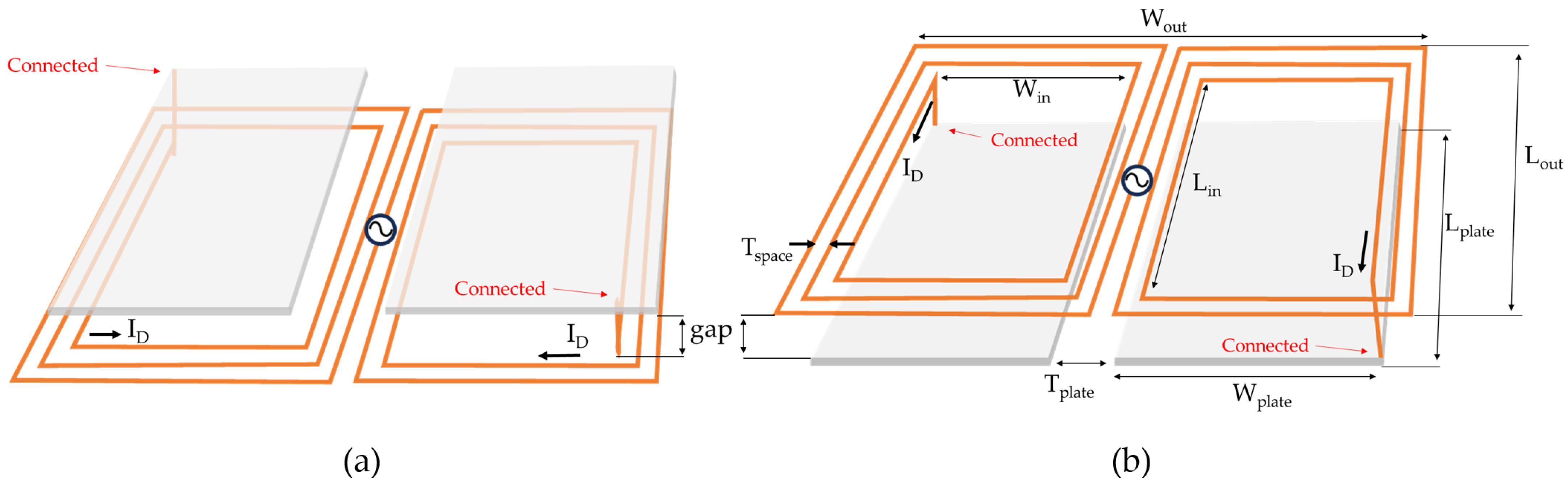
The specifications for the coils and plates used in both models are identical, with the only distinction being the plate arrangement. Table 2 summarizes the dimensions and parameters of the coupler. The DD coil consists of 11 turns on the left and 11 turns on the right relative to the port. Both ends of the coil are connected to the two metal plates. The gap between the plates and the coil is set to 1.5 mm; thus, in the FPA model, the distance between the transmitter and receiver plates is 3 mm closer than in the BPA model. The objective of this study is to analyze the electromagnetic variations resulting from these differences in plate positioning.
Table 2.
Specifications of the proposed HFDD coupler.
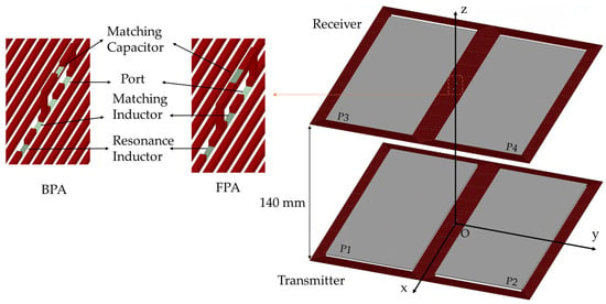
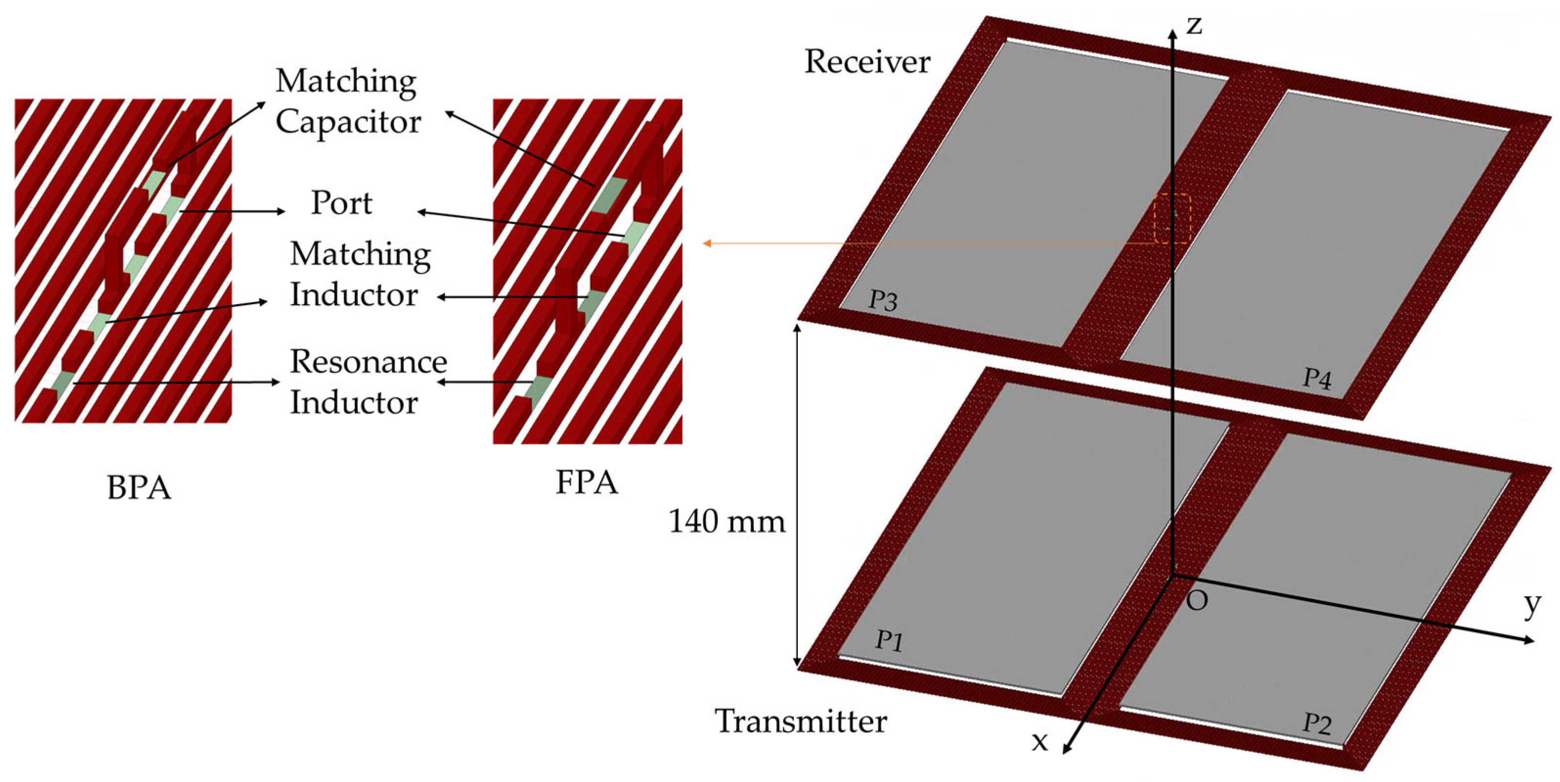
Figure 4 illustrates the HFSS simulation model using the FPA configuration as an example. The port, resonance elements, and impedance matching elements are positioned at the center of the DD coil and are modeled as sheet-type lumped elements. The coils and plates are configured with a copper thickness of 0.5 mm. It should be noted that because the spacing between the coil conductors is very narrow, the windings may appear as a solid surface in the overall visualization. The plates were numbered P1 through P4.
Figure 4.
3D simulation model of the HFDD coupler.
4. Results and Discussion
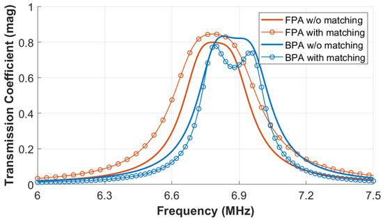
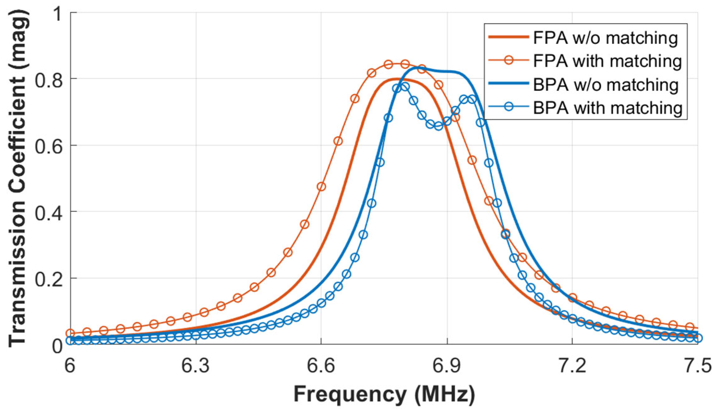
The transmission coefficients (S21) of the FPA and BPA models, observed on a magnitude scale, are presented in Figure 5. The proposed HFDD coupler inherently exhibits strong frequency splitting phenomena due to over-coupling. To address this, impedance matching was performed based on the critical coupling point where the frequency splitting disappears as the gap between the transmitter and receiver increases. For the FPA model, the frequency splitting was mitigated at a transfer distance of 100 mm. In contrast, for the BPA model, the splitting phenomenon was mitigated at a distance of 140 mm under resonance conditions. If the gap is increased further, frequency splitting re-emerges, leading to a decrease in the transmission coefficient. For a fair and consistent comparison under identical operating conditions, both FPA and BPA models were matched and evaluated at an identical transfer distance of 140 mm.
Figure 5.
Transmission coefficients of HFDD coupler.
In the case of the BPA model, the frequency splitting unexpectedly persisted or re-occurred after impedance matching, resulting in a decrease in the transmission coefficient. Conversely, the FPA model did not exhibit frequency splitting after matching, and the transmission coefficient increased by approximately 0.05. The physical basis for these performance differences will be analyzed in the following sections through an evaluation of electromagnetic field distributions and current density profiles.
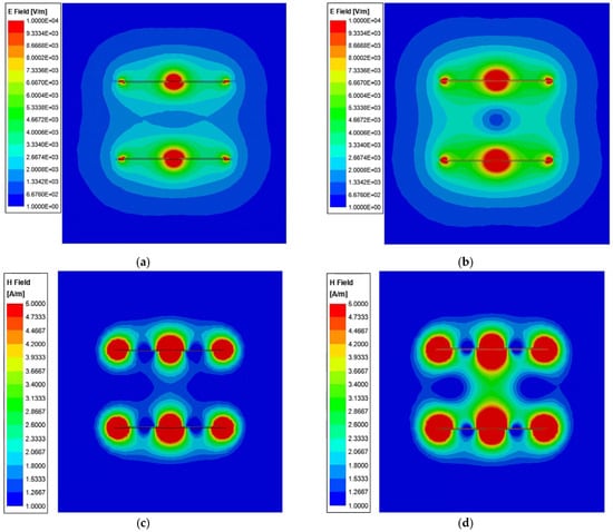
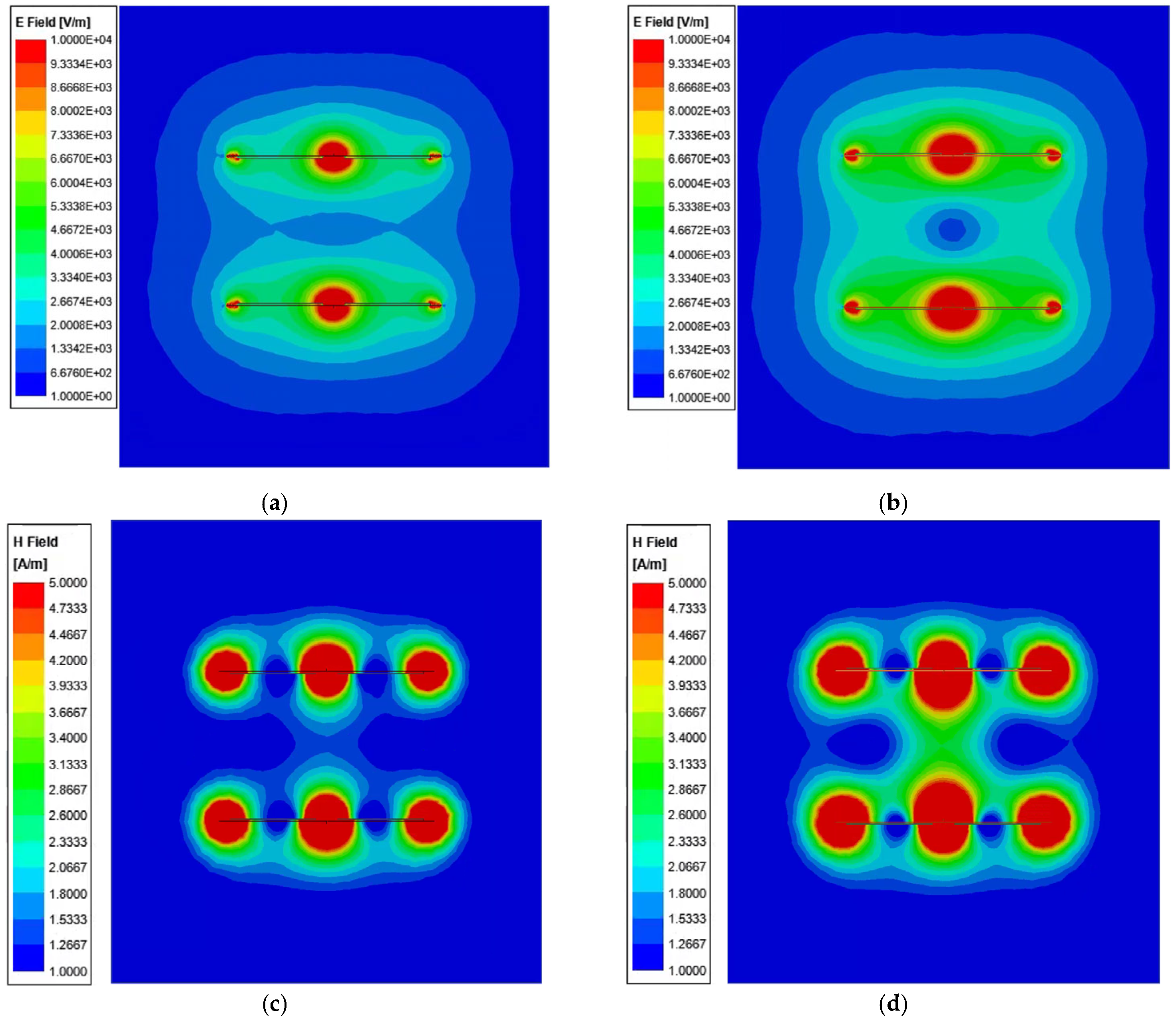
Figure 6 shows the electric and magnetic field intensities of the HFDD coupler for the FPA and BPA structures, plotted using the ComplexMag method. The cross-sectional distribution is captured along the yz-plane passing through the origin, as referenced in the coordinates of Figure 4. Figure 6a,c illustrate the electric and magnetic field distributions of the FPA, while Figure 6b,d represent those of the BPA.
Figure 6.
Electromagnetic field distributions of the HFDD couplers: (a) E-field of FPA; (b) E-field of BPA; (c) H-field of FPA; (d) H-field of BPA.
As predicted, the FPA exhibits lower intensities for both electric and magnetic fields compared to the BPA. To quantitatively evaluate the suppression of the leakage magnetic field, the peak magnetic field intensity was measured at a lateral distance of 200 mm from the coupler center. Under the identical 140 mm transfer distance, the FPA recorded a peak leakage field of 1.12 A/m, which is approximately 28% lower than the 1.56 A/m observed in the BPA. This reduction occurs because the front-positioned plates in the FPA partially interfere with the magnetic flux path, effectively acting as an integrated shield that suppresses the lateral spread of the leakage field. In contrast, the BPA is less affected by eddy currents, leading to a more effective formation of the magnetic field and consequently higher electric field intensities. However, despite these stronger fields, the BPA experiences frequency splitting due to over-coupling. Even when the distance between the transmitter and receiver is intentionally increased to reduce the coupling strength, the frequency splitting does not completely disappear, and the transmission coefficient decreases. This suggests that the strong fields in the BPA do not contribute efficiently to power transfer, a phenomenon further analyzed through current density distributions.
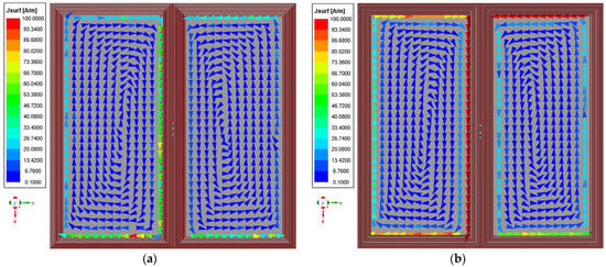
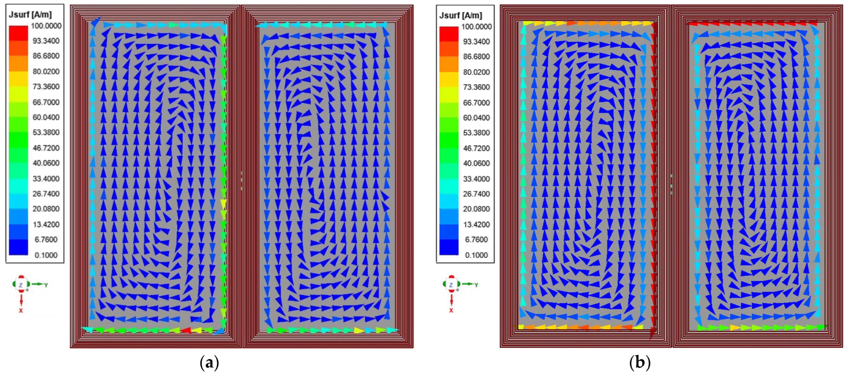
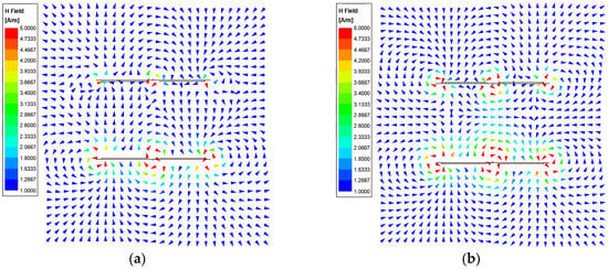
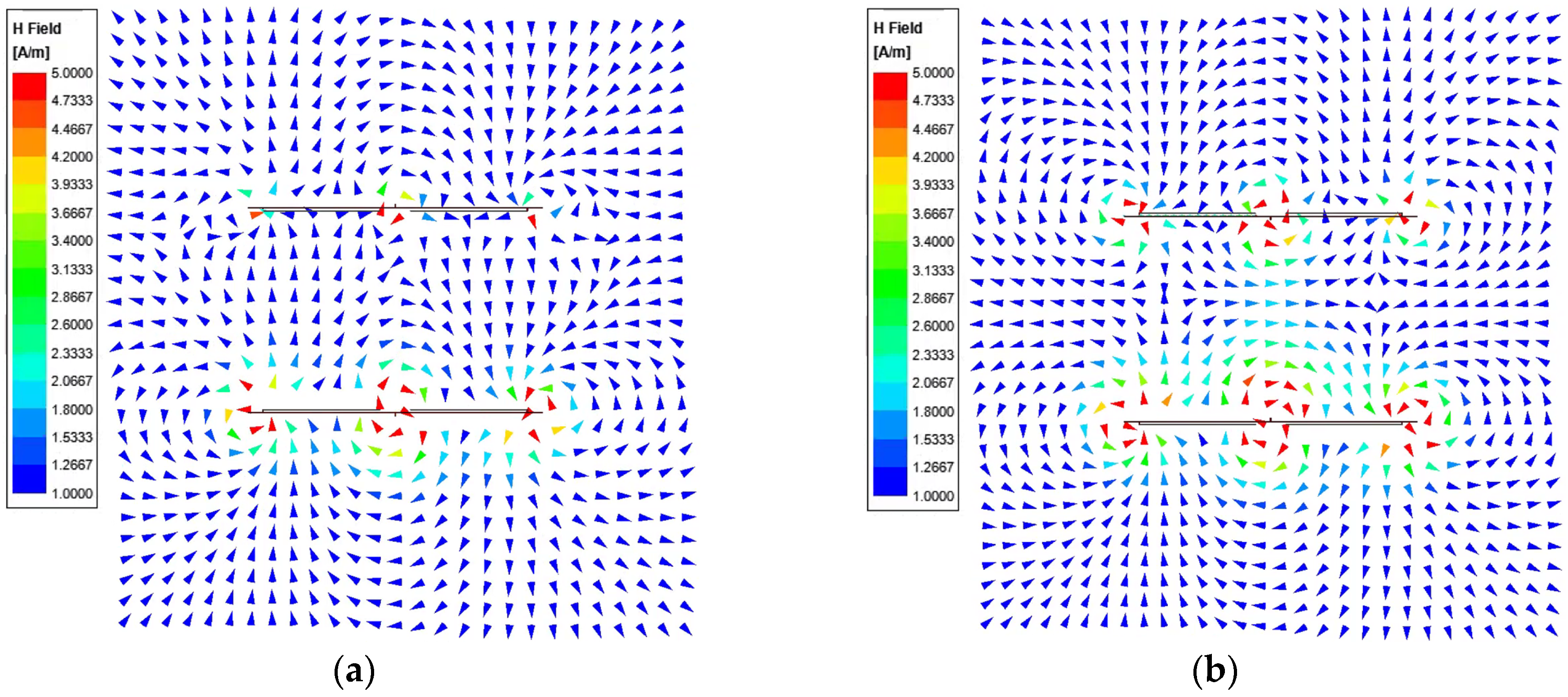
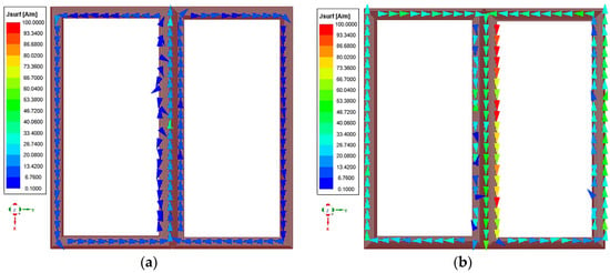
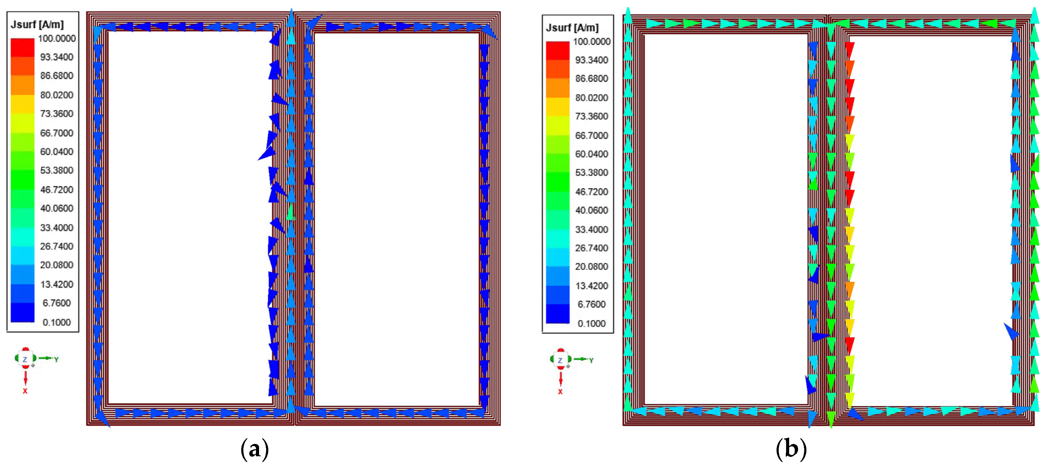
The surface current density distributions on the transmitter plates for the FPA and BPA models are shown in Figure 7a and Figure 7b, respectively. While both models exhibit eddy currents, the BPA shows a significantly stronger formation of these currents. Consequently, as seen in the H-field vector distributions in Figure 8, the magnetic field focusing between the transmitter and receiver is partially canceled out in the BPA model. In contrast, although the magnetic field intensity in the FPA is relatively lower, the direction of magnetic field focusing by the DD coils remains clearly defined. This is further confirmed in Figure 9, which illustrates the current direction in the receiver coils; in the FPA, the current distribution aligns more effectively with the intended induction direction, whereas in the BPA, the induced currents are significantly affected by the counter-acting field produced by the strong eddy currents on the plates.
Figure 7.
Surface current density distributions of Tx plates: (a) FPA; (b) BPA.
Figure 8.
H-field vector distributions: (a) FPA; (b) BPA.
Figure 9.
Current density distributions of Rx DD coils: (a) FPA; (b) BPA.
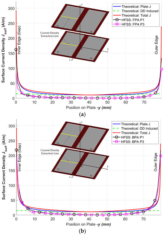
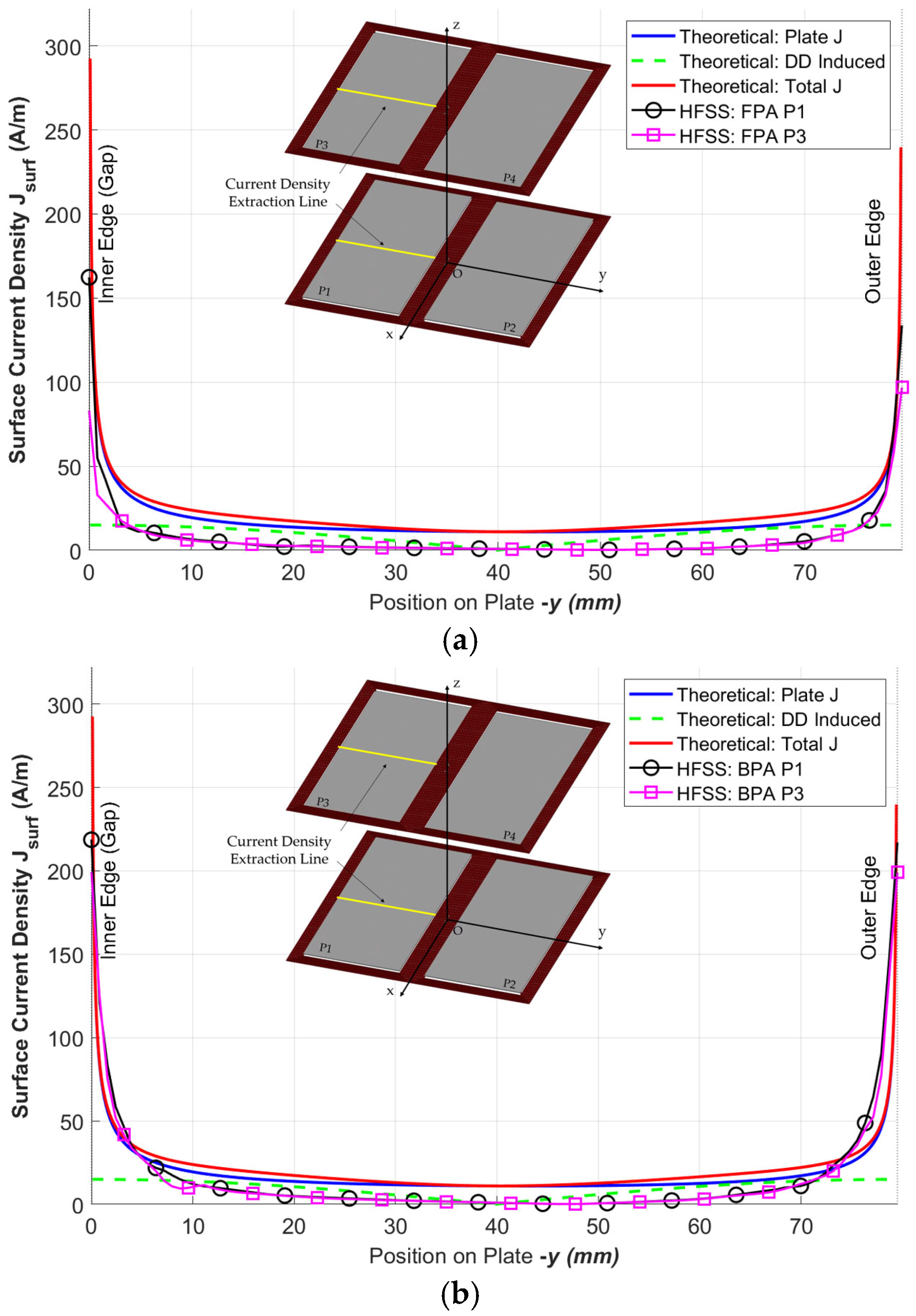
To validate the proposed theoretical model, a comparative analysis was performed between the theoretical current density derived in Section 2 and the surface current density obtained from HFSS. Figure 10 presents the current density profiles calculated along the transverse extraction line of the P1 and P3 plates. The analysis focused on the central region (15 mm to 64.5 mm), where the influence of eddy currents is dominant.
Figure 10.
Comparison of theoretical and simulated surface current densities: (a) FPA; (b) BPA.
Table 3 summarizes the peak values of the induced current distribution along the observation line and the Mean Absolute Error (MAE) between the analytical model and simulations. The FPA model exhibits a peak intensity of approximately 162.39 A/m, which is significantly lower than the 218.62 A/m observed in the BPA. This reduction in the peak value confirms that the front-plate arrangement effectively mitigates the concentration of eddy currents by optimizing the magnetic flux path. Furthermore, the low MAE values presented in Table 3 validate that the derived theoretical model accurately characterizes the average distribution profile of the induced currents for both configurations.
Table 3.
Error analysis of current density between theoretical and simulation results.
Overall, these results indicate that the electromagnetic characteristics of the proposed HFDD coupler can be predicted with high accuracy using the established analytical methodology. The coupling coefficients were calculated using Equation (4) based on the parameters (L, C, LM, CM) extracted after impedance matching. The results are summarized in Table 4. While the parameters for both models showed similar trends, the most significant difference was observed in the CM, with a variance of approximately 0.04 pF. This led to a difference of about 0.04 in the .
Table 4.
Extracted parameters and calculated coupling coefficients for HFDD.
Interestingly, although the BPA appeared to have stronger electromagnetic field intensities, the FPA achieved a higher total coupling coefficient. This result suggests that the intense electromagnetic fields formed in the BPA do not fully contribute to the power transfer coupling. Conversely, the FPA model demonstrates stable coupling characteristics while offering measurable advantages in reducing the magnitude of the generated leakage magnetic field.
5. Conclusions
In this study, an HFDD coupler was proposed and its performance was evaluated through plate arrangement analysis. The FPA model achieved a peak leakage magnetic field intensity of 1.12 A/m, representing a 28% reduction compared to the 1.56 A/m observed in the BPA. Furthermore, the FPA demonstrated a peak current density of 162.39 A/m and a higher total coupling coefficient of 0.203 by minimizing eddy current interference within the primary magnetic flux path.
The results demonstrate that the electromagnetic performance of the HFDD coupler can be tailored by adjusting the plate arrangement to suit specific application requirements. While each configuration has distinct trade-offs, the quantitative analysis confirms that the FPA configuration significantly minimizes field leakage. This suggests that the FPA is a more appropriate solution for mobile robotic applications that prioritize high electromagnetic compatibility and minimal interference with surrounding electronic components. However, from an efficiency perspective, the BPA structure offers the advantage of achieving sufficient transmission coefficients even in a simple resonance state without complex impedance matching. Both structures exhibit distinct advantages and disadvantages. This study on hybrid field coupling is expected to contribute to the development of efficient and stable wireless power transfer methods required for smart manufacturing environments. While this work focuses on analytical and numerical characterization, the results provide a rigorous basis for the physical implementation of HFDD couplers. Future study will build upon these findings to experimentally measure end-to-end efficiency and peak leakage field levels using a hardware prototype.
Author Contributions
Conceptualization, S.P. and H.B.; methodology, S.P.; software, H.B.; validation, H.B.; formal analysis, H.B.; investigation, H.B.; resources, S.P.; data curation, H.B.; writing—original draft preparation, H.B.; writing—review and editing, H.B.; visualization, H.B.; supervision, S.P.; project administration, S.P.; funding acquisition, S.P. All authors have read and agreed to the published version of the manuscript.
Funding
This work was supported by the Soonchunhyang University Research Fund.
Data Availability Statement
The raw data supporting the conclusions of this article will be made available by the authors upon request.
Conflicts of Interest
The authors declare no conflicts of interest.
References
- Fragapane, G.; Ivanov, D.; Peron, M.; Sgarbossa, F.; Strandhagen, J.O. Increasing Flexibility and Productivity in Industry 4.0 Production Networks with Autonomous Mobile Robots and Smart Intralogistics. Ann. Oper. Res. 2022, 308, 125–143. [Google Scholar] [CrossRef] [Scilit]
- Sousa, S.; Costa, H.; Fonseca, R.; Ribeiro, A.; Teixeira, S. Automated System for Transportation and Separation of Textile-Cutting Surpluses: A Case Study in a Portuguese Clothing Company. Sustainability 2025, 17, 4673. [Google Scholar] [CrossRef] [Scilit]
- Zhao, X.; Chidambareswaran, T. Autonomous Mobile Robots in Manufacturing Operations. In Proceedings of the 2023 IEEE 19th International Conference on Automation Science and Engineering (CASE), Auckland, New Zealand, 26–30 August 2023; IEEE: New York, NY, USA, 2023; pp. 1–7. [Google Scholar]
- Cabello, J.R.; Bullejos, D.; Rodríguez-Prieto, A. Analytical Modelling of Arc Flash Consequences in High-Power Systems with Energy Storage for Electric Vehicle Charging. World Electr. Veh. J. 2025, 16, 425. [Google Scholar] [CrossRef] [Scilit]
- Liu, W.; Chau, K.T.; Tian, X.; Wang, H.; Hua, Z. Smart Wireless Power Transfer—Opportunities and Challenges. Renew. Sustain. Energy Rev. 2023, 180, 113298. [Google Scholar] [CrossRef] [Scilit]
- Howaidi, M.; Mahmoud, Y. A Comprehensive Review of Wireless Charging Systems for Automated Guided Vehicles. IEEE Access 2026, 14, 5821–5854. [Google Scholar] [CrossRef] [Scilit]
- Zhu, Q.; Wang, L.; Liao, C.; Guo, Y. Minimizing the Eddy Current Loss in the Chassis When Charging an Electric Vehicle Wirelessly. In Proceedings of the 2014 IEEE Conference and Expo Transportation Electrification Asia-Pacific (ITEC Asia-Pacific), Beijing, China, 31 August–3 September 2014; IEEE: New York, NY, USA, 2014; pp. 1–5. [Google Scholar]
- Bin Hassan, M.N. Smart Wireless Power Transfer: A Review of Integrating AI and Sensing for Next-Generation Robotic and IoT Systems. Preprints 2025, 2025062021. [Google Scholar] [CrossRef] [Scilit]
- Lecluyse, C.; Minnaert, B.; Kleemann, M. A Review of the Current State of Technology of Capacitive Wireless Power Transfer. Energies 2021, 14, 5862. [Google Scholar] [CrossRef] [Scilit]
- Huang, Z.; Lin, Y. A Comprehensive Review of Constant-Output Capacitive Wireless Power Transfer Systems: Topologies, Controls, and Applications. Electronics 2026, 15, 959. [Google Scholar] [CrossRef] [Scilit]
- Lin, C.-H.; Amir, M.; Tariq, M.; Shahvez, M.; Alamri, B.; Alahmadi, A.; Siddiqui, M.; Beig, A. Comprehensive Analysis of IPT v/s CPT for Wireless EV Charging and Effect of Capacitor Plate Shape and Foreign Particle on CPT. Processes 2021, 9, 1619. [Google Scholar] [CrossRef] [Scilit]
- Van Mulders, J.; Delabie, D.; Lecluyse, C.; Buyle, C.; Callebaut, G.; Van Der Perre, L.; De Strycker, L. Wireless Power Transfer: Systems, Circuits, Standards, and Use Cases. Sensors 2022, 22, 5573. [Google Scholar] [CrossRef] [Scilit]
- Luo, B.; Long, T.; Mai, R.; Dai, R.; He, Z.; Li, W. Analysis and Design of Hybrid Inductive and Capacitive Wireless Power Transfer for High-power Applications. IET Power Electron. 2018, 11, 2263–2270. [Google Scholar] [CrossRef] [Scilit]
- Sun, P.; Xiang, Y.; Feng, G.; Rong, E.; Liu, Y.; Zhang, X. A Novel Hybrid Wireless Power Transfer Coupler for Unmanned Aerial Vehicle Application. IEEE Open J. Power Electron. 2026, 7, 316–329. [Google Scholar] [CrossRef] [Scilit]
- He, X.; Qing, X.; Liao, L.; Wu, X. Analysis and Design of Hybrid Wireless Power Transfer with Enhanced and Constant Output Voltage. In Proceedings of the 2024 IEEE 7th International Electrical and Energy Conference (CIEEC), Harbin, China, 10–12 May 2024; IEEE: New York, NY, USA, 2024; pp. 3096–3100. [Google Scholar]
- Li, S.; Xia, K.; Li, T.; Lu, S.; Xia, J.; Liu, Z. A Novel Comb-Shaped Coupler for Hybrid Inductive and Capacitive Wireless Power Transfer System. IEEE Trans. Power Electron. 2025, 40, 4787–4792. [Google Scholar] [CrossRef] [Scilit]
- Qing, X.; Li, Z.; Wu, X.; Liu, Z.; Zhao, L.; Su, Y. A Hybrid Wireless Power Transfer System with Constant and Enhanced Current Output Against Load Variation and Coupling Misalignment. IEEE Trans. Power Electron. 2023, 38, 13219–13230. [Google Scholar] [CrossRef] [Scilit]
- Fu, C.; Wang, D.; Zhao, Q. A Compact and Coupling-Smooth Magnetic Coupler Design for AGV Wireless Charging Application. IEEE Access 2023, 11, 11288–11297. [Google Scholar] [CrossRef] [Scilit]
- Pan, W.; Liu, C.; Tang, H.; Zhuang, Y.; Zhang, Y. An Interoperable Electric Vehicle Wireless Charging System Based on Mutually Spliced Double-D Coil. IEEE Trans. Power Electron. 2024, 39, 3864–3872. [Google Scholar] [CrossRef] [Scilit]
- Wu, M.; Cui, H.; Zhao, C.; Yang, X.; Chen, W.; Wang, L.; Yu, X. Modeling of the DD Planar Coil with Ferrite for the Wireless Power Transfer System. In Proceedings of the 2022 IEEE 5th International Electrical and Energy Conference (CIEEC), Nangjing, China, 27–29 May 2022; IEEE: New York, NY, USA, 2022; pp. 4836–4841. [Google Scholar]
- Prosen, N.; Domajnko, J.; Milanovič, M. Wireless Power Transfer Using Double DD Coils. Electronics 2021, 10, 2528. [Google Scholar] [CrossRef] [Scilit]
- Dai, Z.; Li, M.; Xu, H.; Ji, M.; Zhang, L. Strong Misalignment Tolerance Wireless Power Transfer with Active Adjustment of Magnetic Shielding. AIP Adv. 2024, 14, 015320. [Google Scholar] [CrossRef] [Scilit]
- Bang, K.; Bae, H.; Park, S. Resonant-Based Wireless Power Transfer System Using Electric Coupling for Transparent Wearable Devices and Null Power Points. Sensors 2023, 23, 1535. [Google Scholar] [CrossRef] [Scilit]
- Badwey, M.A.; Abbasy, N.H.; Eldallal, G.M. Extended Results for a Developed 10 kW LC-Compensated Hybrid Wireless Power Transfer System. In Proceedings of the 2022 23rd International Middle East Power Systems Conference (MEPCON), Cairo, Egypt, 13–15 December 2022; IEEE: New York, NY, USA, 2022; pp. 1–8. [Google Scholar]
- Lu, F.; Zhang, H.; Hofmann, H.; Mi, C.C. An Inductive and Capacitive Combined Wireless Power Transfer System With LC-Compensated Topology. IEEE Trans. Power Electron. 2016, 31, 8471–8482. [Google Scholar] [CrossRef] [Scilit]
- Wen, H.; Wang, P.; Li, J.; Yang, J.; Zhang, K.; Yang, L.; Zhao, Y.; Tong, X. Improving the Misalignment Tolerance of Wireless Power Transfer System for AUV with Solenoid-Dual Combined Planar Magnetic Coupler. J. Mar. Sci. Eng. 2023, 11, 1571. [Google Scholar] [CrossRef] [Scilit]
- Alkasir, A.; Abdollahi, S.E.; Abdollahi, S.; Wheeler, P. Analytical Modeling of Self- and Mutual Inductances of DD Coils in Wireless Power Transfer Applications. J. Electromagn. Eng. Sci. 2022, 22, 162–170. [Google Scholar] [CrossRef] [Scilit]
- Xie, S.; Wu, L.; Zhang, X.; Huang, J.; Li, L. Misalignment-Tolerant Wireless Power Transfer System Based on Double-Layer Quadrature Double-D Coil With Magnetic Field Control. IEEE Trans. Transp. Electrif. 2024, 10, 9945–9958. [Google Scholar] [CrossRef] [Scilit]

Disclaimer/Publisher’s Note: The statements, opinions and data contained in all publications are solely those of the individual author(s) and contributor(s) and not of MDPI and/or the editor(s). MDPI and/or the editor(s) disclaim responsibility for any injury to people or property resulting from any ideas, methods, instructions or products referred to in the content. |
© 2026 by the authors. Licensee MDPI, Basel, Switzerland. This article is an open access article distributed under the terms and conditions of the Creative Commons Attribution (CC BY) license.