


Abstract
The insufficient bearing capacity of the foundation at waste dumps can easily lead to landslides and other geohazards. At present, discrepancies between the calculated bearing capacity of such foundations and actual field performance are a major cause of these accidents. Therefore, further research into methods for accurately estimating the foundation bearing capacity of waste dumps to guide engineering practice is crucial for preventing such incidents. This study employs a combination of theoretical and case analysis to examine the current calculation methods. We discover that the calculated values are smaller than the actual values. Moreover, by taking into account both the upper load of the waste dumps and the bearing capacity of the lower foundation, we analyzed the main problems leading to the underestimation. In response to the aforementioned issues, this study suggests incorporating the Boussinesq equation into the calculation of the upper load to account for the load distribution across various slope forms and the diffusion and superposition of stress at different foundation positions and depths. Simultaneously, the foundation’s bearing capacity is calculated to increase with burial depth, aligning with the stress at different positions. Finally, a new method for calculating the bearing capacity of foundations at waste dumps was developed. The bearing capacities of the waste dump foundation and the weakest point determined using the proposed method are validated through a case study and FLAC3D numerical simulation. This study can provide a reference for calculating the bearing capacity of foundations in similar waste dumps.
1. Introduction
Large amounts of waste rock and soil generated from open-pit mining have created numerous waste dumps [1]. Waste dumps can occupy more than half of the total land area of a mine. In China, this proportion ranges from 30% to 50% [2], while in Russia [3] and the United States [4] it also reaches around 50%. Open-pit mining produces a substantial quantity of waste rock. As a result, the haul distance exerts a considerable influence on the mine’s economic benefits. This implies that the waste dumps should not be located too far from the mine. Owing to the influence of the topography and geological conditions of the mining area, a substantial quantity of waste rock can only be stacked on the Quaternary soil layer or soft rock, thereby forming waste dumps located on weak foundations. For waste dumps with weak foundations, an accurate calculation of foundation bearing capacity is of importance. Underestimating the bearing capacity will lead to space waste, whereas overestimating it will trigger geological disasters such as landslides. In 2011, a landslide occurred at an iron waste dump in Yunnan, China, due to the influence of a weak foundation and rainfall [5]. In 2018, a large-scale landslide occurred at the Mae Moh mine waste dump in Thailand, driven by the weak foundation and groundwater [6]. To address the above problem, some researchers have studied the methods for calculating the bearing capacity of waste dump foundations [7,8]. They adapted the Prandtl and Terzaghi bearing capacity calculation methods, which were originally developed for building foundations in soils, and directly simplified them to apply in waste dump. This approach is currently the most widely used. However, this method still exhibits certain errors when calculating the bearing capacity of waste dumps with weak foundations. Previous researchers analyzed the foundation bearing capacity using the Fast Lagrangian Analysis of Continua (FLAC) numerical simulation method, confirming its high reliability [9]. Nevertheless, existing studies have yet to establish a comparative calculation framework for load and bearing capacity that adequately accounts for the spatial morphology of waste dumps. Furthermore, there is no quantitative method has been rigorously derived for evaluating the bearing capacity of waste dumps constructed on soft soil foundations. This study theoretically analyzes the limitations of existing calculation methods, introduces the Boussinesq equation as a theoretical foundation, and subsequently proposes a novel approach to evaluate the bearing capacity of waste dump foundations. The validity and accuracy of the proposed method are further verified through numerical simulations and a case study calculation. The proposed method effectively mitigates the large discrepancies commonly encountered in bearing capacity evaluations of weak foundations beneath waste dumps by explicitly accounting for the load distribution characteristics associated with dump slope morphology, the diffusion and superposition of loads within the foundation, and the variation in foundation bearing capacity with burial depth. Consequently, this method provides a robust and generalizable framework for calculating the foundation bearing capacity of similar waste dump engineering projects. This study can provide insights and references for scientific research institutions, design organizations, and safety evaluation entities concerned with waste dump stability.
2. Materials and Methods
Several approaches are commonly used for stability and deformation analysis of waste dumps. For instance, limit equilibrium method can be used for slope stability analysis, while numerical methods (e.g., finite element method) are typically adopted for stress–strain and deformation analysis. However, these methods primarily focus on the influence of shear strength and deformation characteristics of geomaterials on the stability and deformation of waste dumps. The role of foundation bearing capacity in controlling waste dump stability still requires further investigation. Moreover, classical calculation methods often fail to adequately account for the influence of slope geometry on load distribution and the effect of embedment depth on bearing capacity. Therefore, a newly proposed method is developed in this section within the framework of bearing capacity analysis.
2.1. Classical Calculation Methods and Their Limitations
2.1.1. Classical Calculation Methods
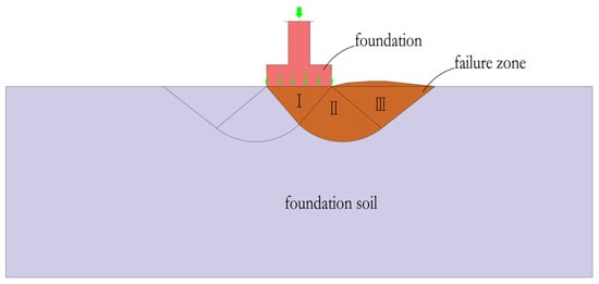
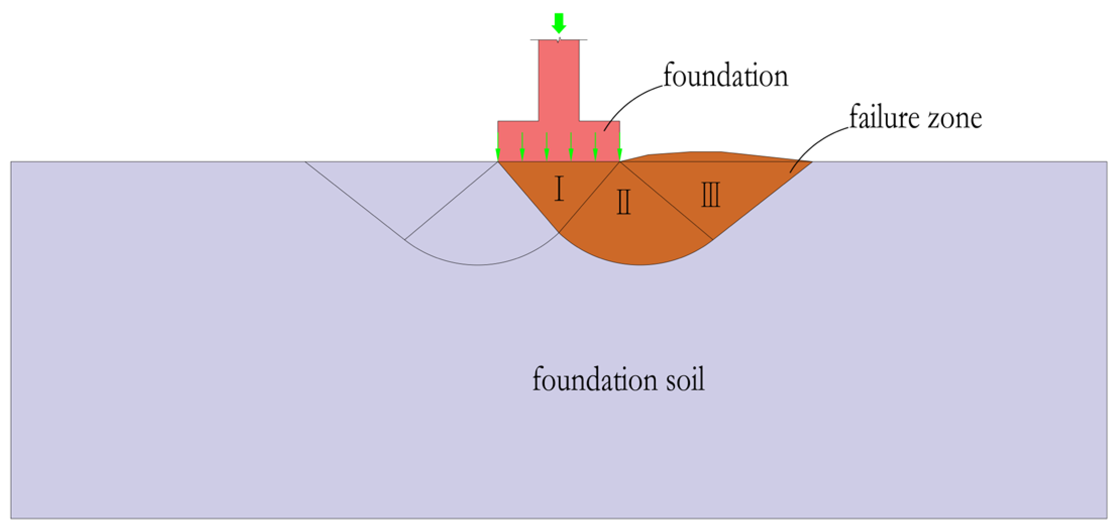
In 1920, Prandtl [10] proposed a formula for calculating the ultimate load of weightless media, which was subsequently introduced into soil mechanics by Reissner [11] for evaluating bearing capacity of foundation. Under the ultimate loading condition, this method divides the sliding soil mass beneath the foundation into three zones: the Rankine active zone (I), the Rankine passive zone (II), and the transition zone (III) [12], as shown in Figure 1. By applying the rigid body equilibrium equations to the three zones, it can be obtained that:
where and represent the bearing capacity coefficient of foundation; c is the soil cohesion, kPa; q denotes the side load above the base surface, kPa.
Figure 1.
Prandtl’s bearing capacity failure mechanism.
By omitting the second term in the above equation (i.e., neglecting the load acting above the foundation base) and by disregarding the slope geometry of the waste dump, the load applied to the upper part of the foundation is directly taken as the maximum unit weight of the waste dump, denoted as , and the following expression is obtained:
where represents the unit weight of waste dump fill, kN/m3; denotes the height of the waste dump, m.
This equation is commonly employed to determine the maximum allowable height of waste dumps. Some researchers have also applied Terzaghi’s [13] bearing capacity formula to calculate foundation bearing capacity for waste dumps. The underlying calculation principle and associated limitations are similar. The formula considering Terzaghi’s approach is shown in Equation (5):
2.1.2. Limitation of Classical Calculation Methods
Due to the large-area filling in waste dump, the internal regions provide mutual counterpressure to the other. Consequently, when the foundation is subjected to the load from the overlying fill, can exhibit relatively large settlement [14]. However, in regions near the external slopes of the waste dump, the presence of a free surface prevents the counteracting pressure from fully developing, resulting in insufficient foundation bearing capacity [15]. Consequently, shear failure occurs near the toe of the slope, while cracks develop along the rear edge, propagating both downward and toward the slope, ultimately compromising the stability of the waste dump. From the perspective of the failure mode caused by the insufficient bearing capacity of the waste dump foundation, the load on the slope area and the favorable conditions created by the counter-pressure are particularly important for the stability of the waste dump. When the slope of a waste dump is extremely gentle, the foundation stress in the slope zone (counter-pressure load) can be considered nearly equal to the load from the overlying fill. Under such conditions, the waste dump is unlikely to experience failure. Therefore, understanding the loads from different slope morphologies and the beneficial effects of burial depth is crucial for determining the bearing capacity of waste dump foundations.
Equation (4) indicates that current methods for calculating loads in waste dumps directly adopt the approach, without accounting for the influence of side slope morphology on the load distribution. This method overestimates the load in the side slope area.
Current methods for calculating the bearing capacity of waste dump foundations are derived from soil mechanics’ ultimate bearing capacity formulas. However, these formulas are based on assumptions relevant to foundations of civil buildings, such as load transmission from a superstructure, vertically applied loads, and failure confined to the shallow soil layer. Since waste dumps lack a conventional foundation for load transfer, the stress conditions vary across different areas, resulting in differing foundation failure modes. In particular, when a waste dump foundation fails, and the sliding surface extends into deeper layers. The formula considers only the soil layer’s shear strength to calculate ultimate bearing capacity, ignoring the additional capacity contributed by burial depth, thereby underestimating the foundation’s actual bearing capacity. Therefore, when calculating the bearing capacity of the waste dump foundation, a method that accounts for depth effects is more in line with reality.
To address the shortcoming mentioned above, Jiang et al. [7] proposed modifications to the Prandtl formula, primarily to improve the method for calculating the overlying load. The improved formula treats the entire waste dump slope as a triangular load and simulates different slope angles by adjusting its distribution. The interior of the waste dump is modeled as a uniformly distributed load. The bearing capacity of the waste dump foundation is then calculated by solving the moment balance equation. While the overall slope angle is considered, the method does not take the internal platforms or the slope surfaces within the waste dump into account. In a waste dump, the slope angle of each bench generally corresponds to the repose angle of the stacked materials, and each bench typically leaves a platform 20–30 m in width. Therefore, further refinement is needed to account for the varying shapes of the bench of the waste dump.
2.1.3. Case Study
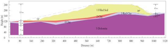
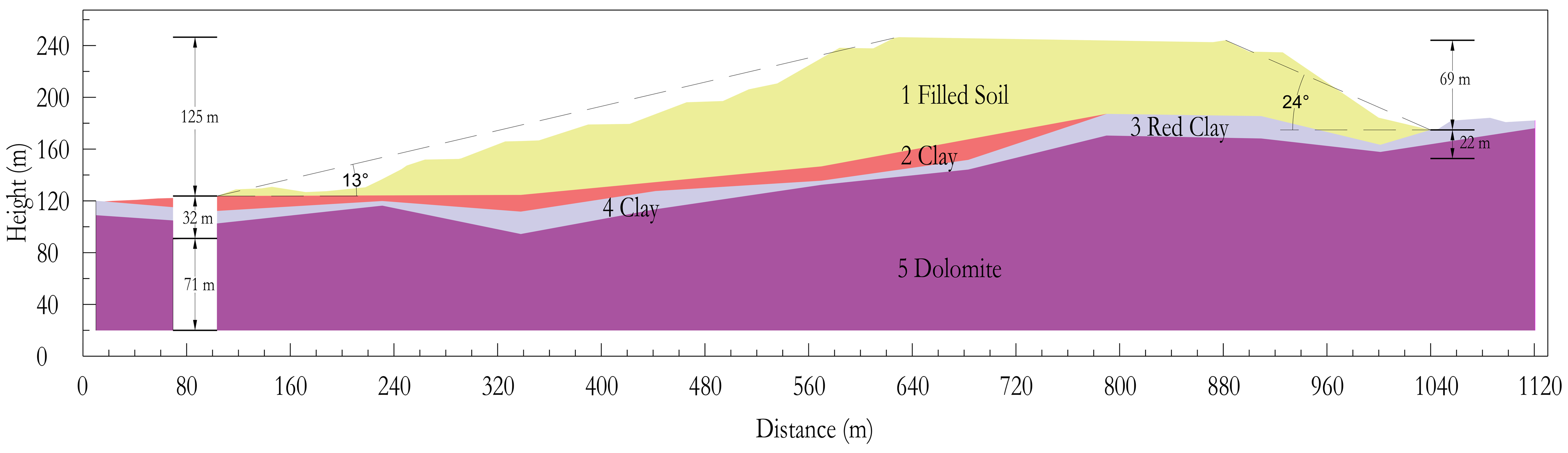
To illustrate the limitations of classical calculation methods, this study conducts an analysis on an engineering case. A soil-based phosphate mine waste dump in Yunnan Province was constructed in 2012. By 2025, the dump had been in operation for 13 years and reached a height of 125 m, with an average soil layer thickness of 30 m, making it a representative example of a waste dump with a soil foundation. The overall slope angle on the left side of the waste dump is 13°, and the height is 125 m. Due to the reverse slope, the absence of surrounding protective facilities, and its position on the mining land, the right side underwent natural piling up, resulting in the formation of a temporary slope with a 24-degree angle and a height of 69 m. The stability coefficient of the waste dump under in situ conditions is set to 1.25. The right-side slope was formed by uncontrolled on-site dumping, and local failures occurred during operation, indicating potential deficiency in its design. Its stability is close to the limit equilibrium state and difficult to satisfy stability and safety requirements. Although engineering remediation works are currently being implemented by the responsible authorities, this slope still provides a valuable case for comparative analysis. This study conducted a detailed investigation of the waste dump layers, including on-site direct shear and plate load tests, to establish a representative profile of the dump, as shown in Figure 2. The parameters of each layer are summarized in Table 1.
Figure 2.
Cross-section of the waste dump.
Table 1.
Parameters of the layers of the waste dump.
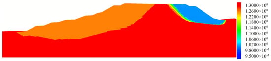
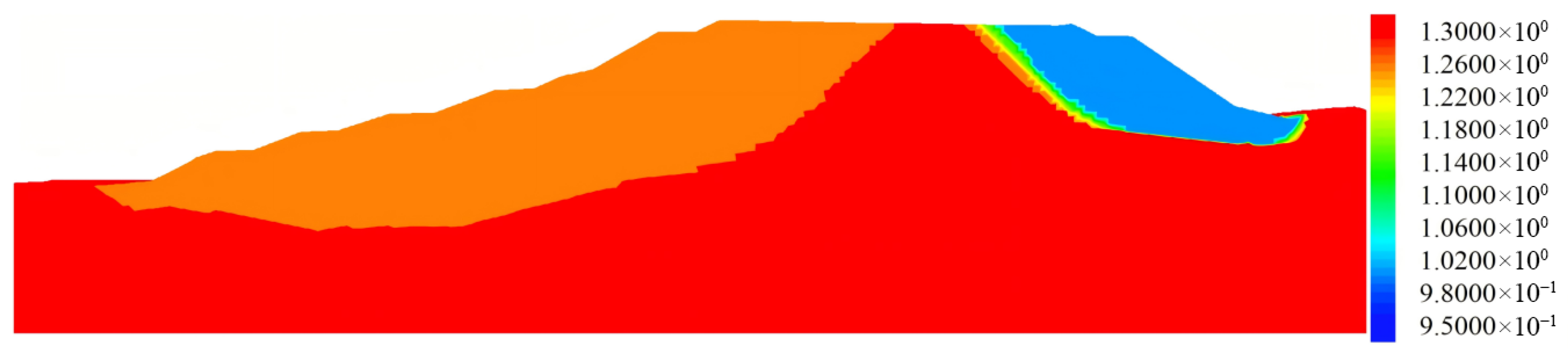
Previous studies have demonstrated that FLAC 3D can accurately simulate the stability and the evolution of displacement fields during slope deformation [16,17]. In addition to field experiments and theoretical calculations, this study uses the numerical simulation method of FLAC 3D for verification. The model dimension is 1110 m in the x-direction, 228 m in the z-direction, and 200 m in the y-direction, more details about the dimension can be found in Figure 1. A free boundary condition is applied at the top, a fully fixed boundary at the bottom, and normal fixed boundaries on the other sides. Mohr-Coulomb constitutive model is adopted for each geotechnical layer in the simulation. Strength reduction method was adopted to analyze the stability of the waste dump. In this approach, the shear strength parameters of the geomaterial are gradually reduced until the model reaches a limit equilibrium state, then the corresponding reduction factor at this point is taken as the factor of safety [18,19]. To avoid the influence of boundary conditions on the analysis, the central cross-section of the model is selected for evaluation. The stability contour map obtained from simulation calculations with the parameters in Table 1 is shown in Figure 3. It can be seen that the stability coefficient of the left slope is 1.26, and that of the right slope is 1.00 to 1.02. The height of the left slope is 125 m. Due to the relatively gentle overall slope angle, its stability coefficient is higher than that of the right slope. This further confirms the unreasonableness of directly assuming the upper load as P = .
Figure 3.
Contour map of stability calculation results.
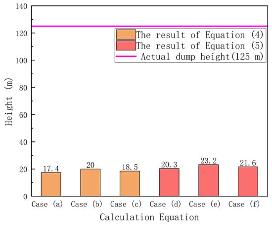
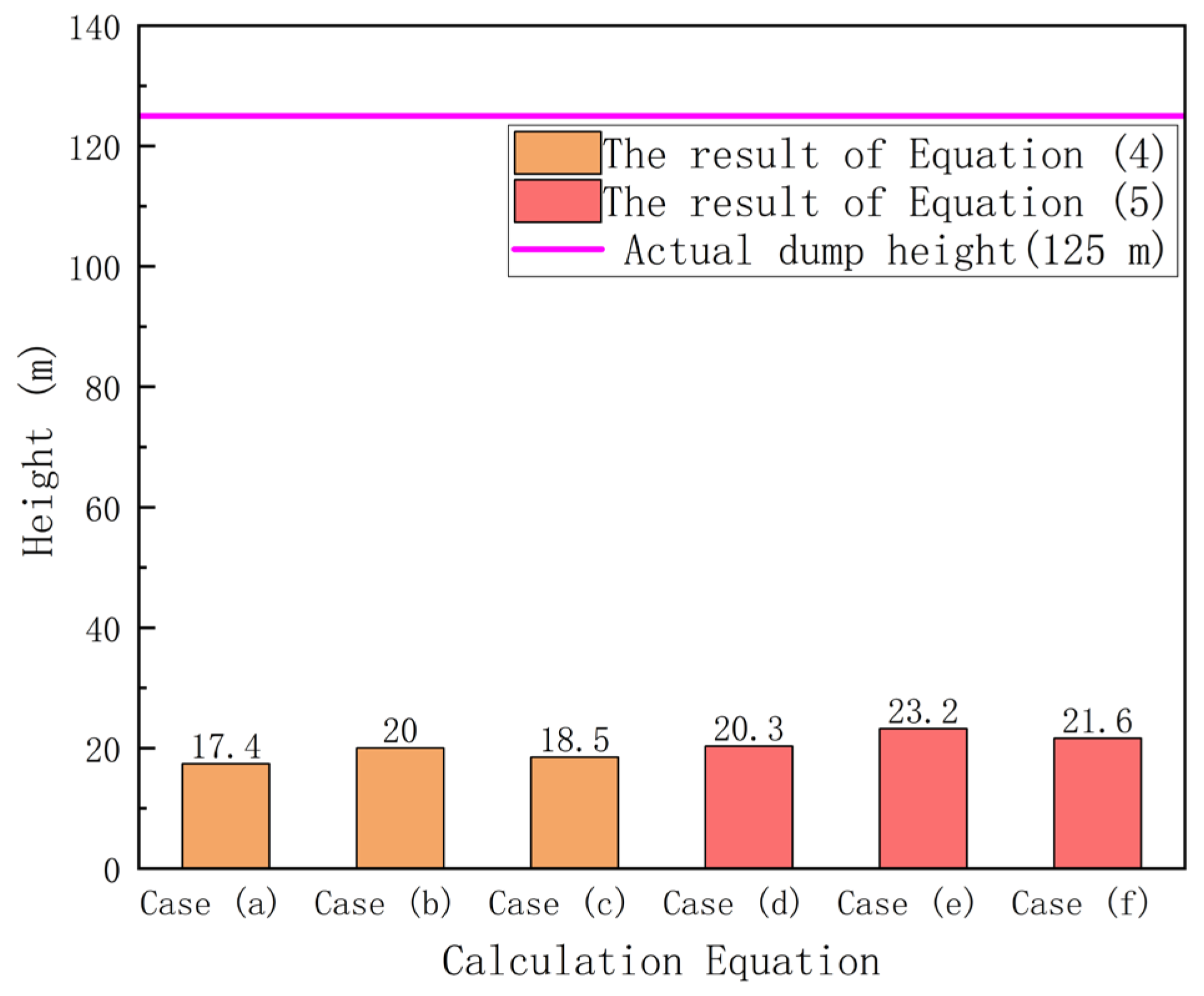
Further calculations were performed via the current bearing capacity formula (Equation (4)) based on Prandtl, and the bearing capacity formula (Equation (5)) based on Terzaghi. The ultimate dump heights obtained from the two methods are compared in Table 2. The comparison between the calculated ultimate dump height as well as the actual dump height is presented in Figure 4. Here, Case (a) denotes the ultimate dump height determined using Equation (4) considering parameters from Layer 2; Case (b) denotes the ultimate dump height determined using Equation (4) considering parameters from Layer 3; Case (c) denotes the ultimate dump height determined using Equation (4) considering parameters from Layer 4; Case (d) denotes the ultimate dump height determined using Equation (5) considering parameters from Layer 2; Case (e) denotes the ultimate dump height determined using Equation (5) considering parameters from Layer 3; Case (f) denotes the ultimate dump height determined using Equation (5) considering parameters from Layer 4. It can be seen that the calculated maximum dump height is significantly lower than the actual dump height even after incorporating safety reserves, indicating that the classical calculation method yields underestimated results compared to reality.
Table 2.
Calculation results of ultimate dump height.
Figure 4.
Comparison of calculated and actual dump height.
2.2. Calculation Method Based on Boussinesq Equation
Classical calculation methods have several limitations, the overlying load is not accounted for slope morphology or the diffusion and superposition of stresses, and the beneficial effects of burial depth is neglected during the calculation of foundation bearing capacity [20]. To address the aforementioned limitations, this study employs the Boussinesq equation to account for the morphology of the slope benches and to consider the distribution of loads from different benches across varying foundation depths. The bearing capacity is further adjusted for depth to correspond with the distribution of the overlying load at different foundation depths. The Boussinesq equation, proposed by the French physicist and mathematician Joseph Valentin Boussinesq [21], provides an analytical solution for the stress, strain, and displacement at any point within a semi-infinite, homogeneous, isotropic elastic half-space subjected to a vertical concentrated load applied at its surface. Through integration, the additional stresses induced by loads of various shapes in the foundation can be calculated. Therefore, its application to waste dump load calculations allows to consider both the loads from varying slope morphologies and the additional stresses at different foundation locations. In specific calculations, each bench can be divided into the triangular loads in the slope edge areas and rectangular uniformly distributed loads in the internal areas. The benches are stacked upward layer by layer to form entire waste dump, with the detailed calculation method elaborated in Section 3. However, applying this method to calculate the additional stresses induced by the waste dump at different locations in the foundation exists limitations: the theory assumes the foundation is a semi-infinite, homogeneous, isotropic elastic half-space, so calculations can only treat the foundation as uniform soil layers within this semi-infinite space based on the assumptions. Nevertheless, this calculation method has been widely applied and validated in soil mechanics, proving that its accuracy is acceptable for engineering practice [22]. Studies such as Hatami et al. [23] have also confirmed that the pressures calculated by this method tend to be slightly larger than measured values, making it conservative and sufficient to meet requirements of engineering accuracy.
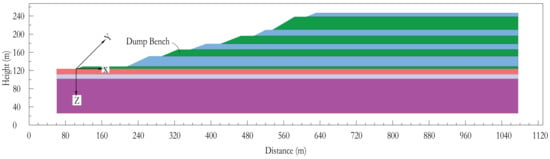
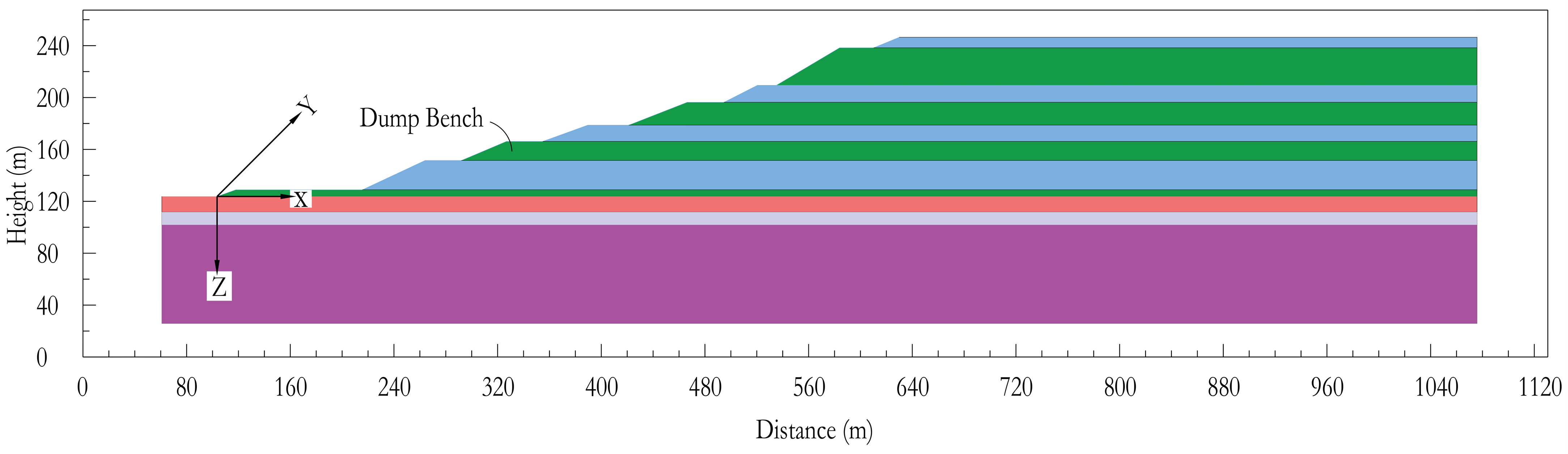
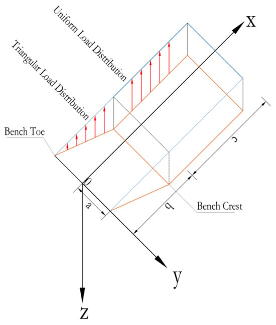
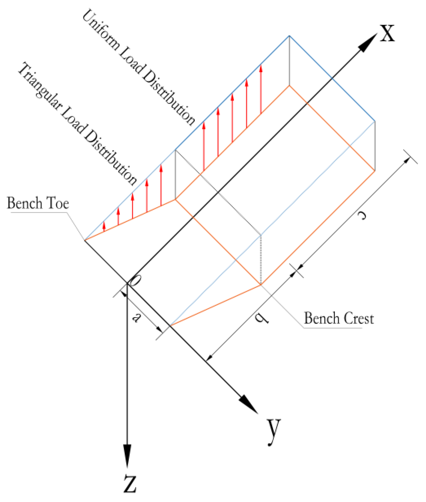
Considering that foundation stress varies across regions, the stress at different foundation depths at the toe or top of each bench in the slope area is calculated and compared with the corresponding bearing capacity. The loads on both sides of the calculation point are considered to be diffused to the calculation point to account for the beneficial effect of counter-pressure. The foundation bearing capacity of the entire waste dump is considered adequate if it meets the required criteria at all locations. The overall calculation model for this case is illustrated in Figure 5. For clarity, the direction perpendicular to the slope strike is defined as the x-axis, the direction parallel to the slope strike as the y-axis, and the vertical direction as the z-axis, with the origin located at the center of the slope toe. The calculation model for each bench is shown in Figure 6.
Figure 5.
Calculation model of the waste dump.
Figure 6.
Calculation model of a single bench in the waste dump.
3. Results
In this section, calculations are performed using the computational model based on the Boussinesq equation developed in Section 2. The additional stress induced by the triangular load at the center of the slope toe within a single-bench slope region can be calculated via the following equations:
where a denotes half the length of the slope in the y-direction, m; b denotes the length of the slope in the x-direction, m; z indicates the calculation depth, m.
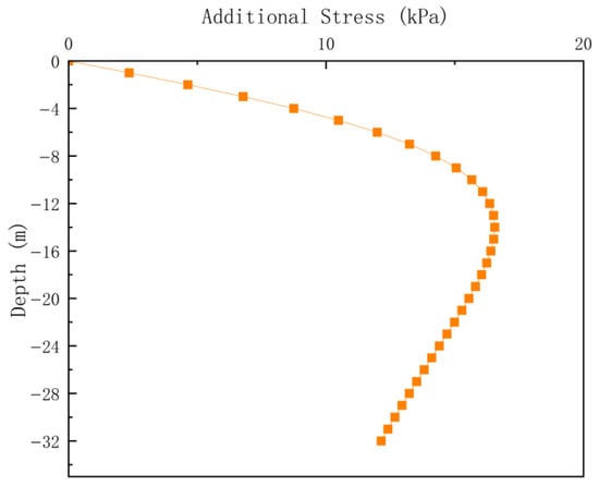
The relevant parameters of the first bench are listed in Table 3. These values are substituted into Equations (6) and (7) to calculate the triangular load at the center of the slope toe for the first bench, at 1 m intervals from the ground surface to a depth of 32 m. The calculation results are plotted in Figure 7.
Table 3.
Parameters of the first bench.
Figure 7.
Distribution of additional stress under triangular load on the slope at the calculation point.
The additional stress at the center of the toe of a single-bench slope, induced by a uniformly distributed rectangular load on the rear face of the slope, is calculated through the following equation:
where c represents the length of the waste dump along the slope in the x-direction, m.
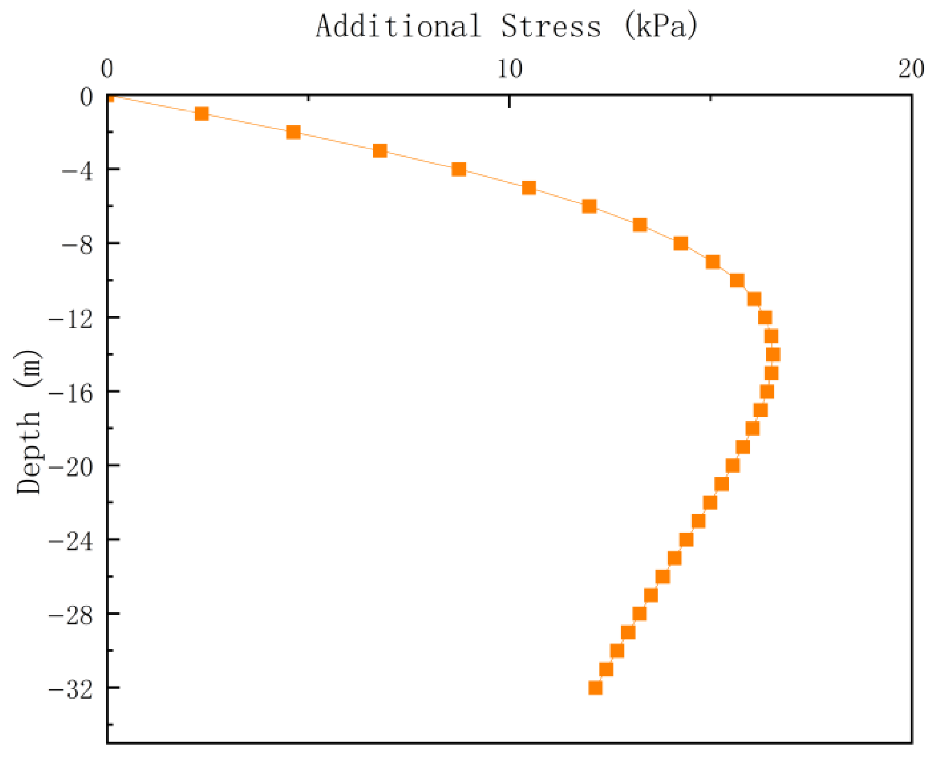
By substituting the parameters of the first bench into Equation (8), the additional stress induced by the rectangular load of the first bench is calculated from the ground surface to a depth of 32 m beneath the slope center, see Figure 8.
Figure 8.
Distribution of additional stress under rectangular load at the calculation point.
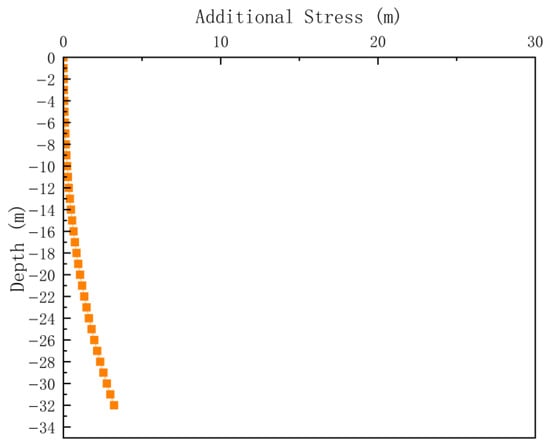
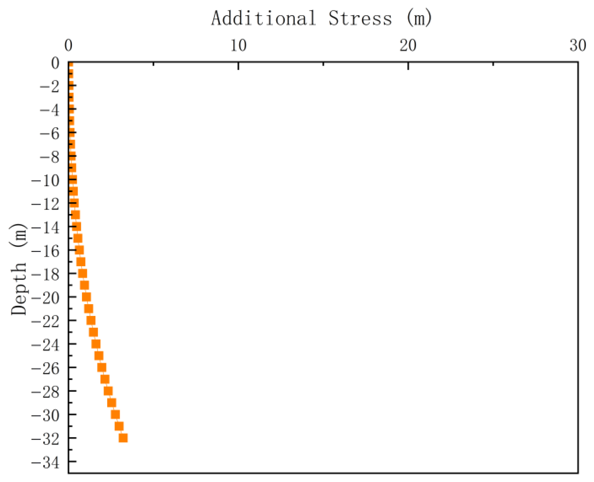
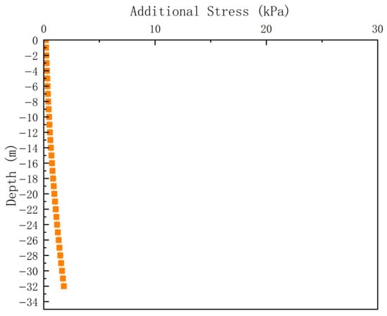
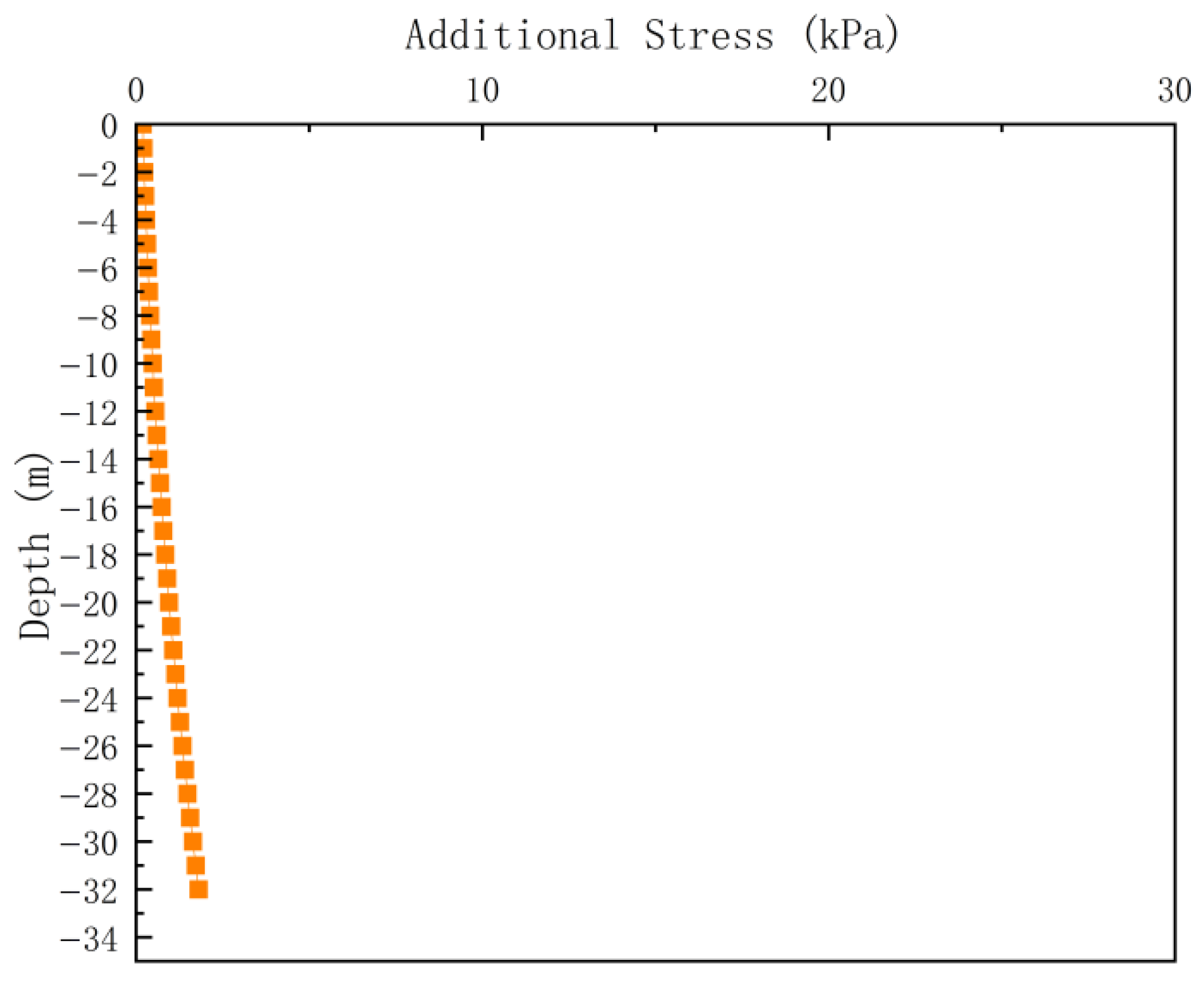
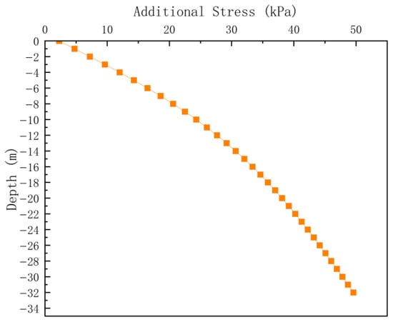
Further calculations were conducted for the loads generated by the second and third benches within the range from the ground surface to a depth of 32 m, as shown in Figure 9 and Figure 10, respectively. The results indicate that, due to the relatively wide platform at the first bench, the additional stress from the second and third benches at the ground surface is negligible at the calculation point. The maximum additional stress occurs at a depth of 32 m beneath the calculation point, but it remains at a low value of 1.8 kPa. This pattern is consistent with the stress-diffusion model: as the load propagates farther, its influence penetrates deeper at the observation point, while the magnitude of the additional stress decreases. For engineering applications, calculations up to this stage are generally sufficient. In this study, the additional stresses generated by each subsequent bench are calculated and superimposed to obtain the total additional stress induced by the entire waste dump at the calculation point, as shown in Figure 11. Owing to the large scale of the waste dump, the total additional stress at the slope toe increases with depth. When verifying foundation bearing capacity, both additional stresses and variations in soil bearing capacity with depth should be considered. It is therefore inappropriate to compare the maximum waste dump load with the bearing capacity of the surface soil.
Figure 9.
Distribution of additional stress at the calculation point of the second bench.
Figure 10.
Distribution of additional stress at the calculation point of the third bench.
Figure 11.
Distribution of total additional stress at the calculation point.
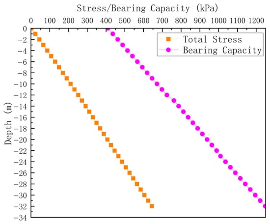
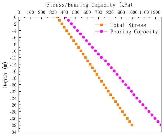
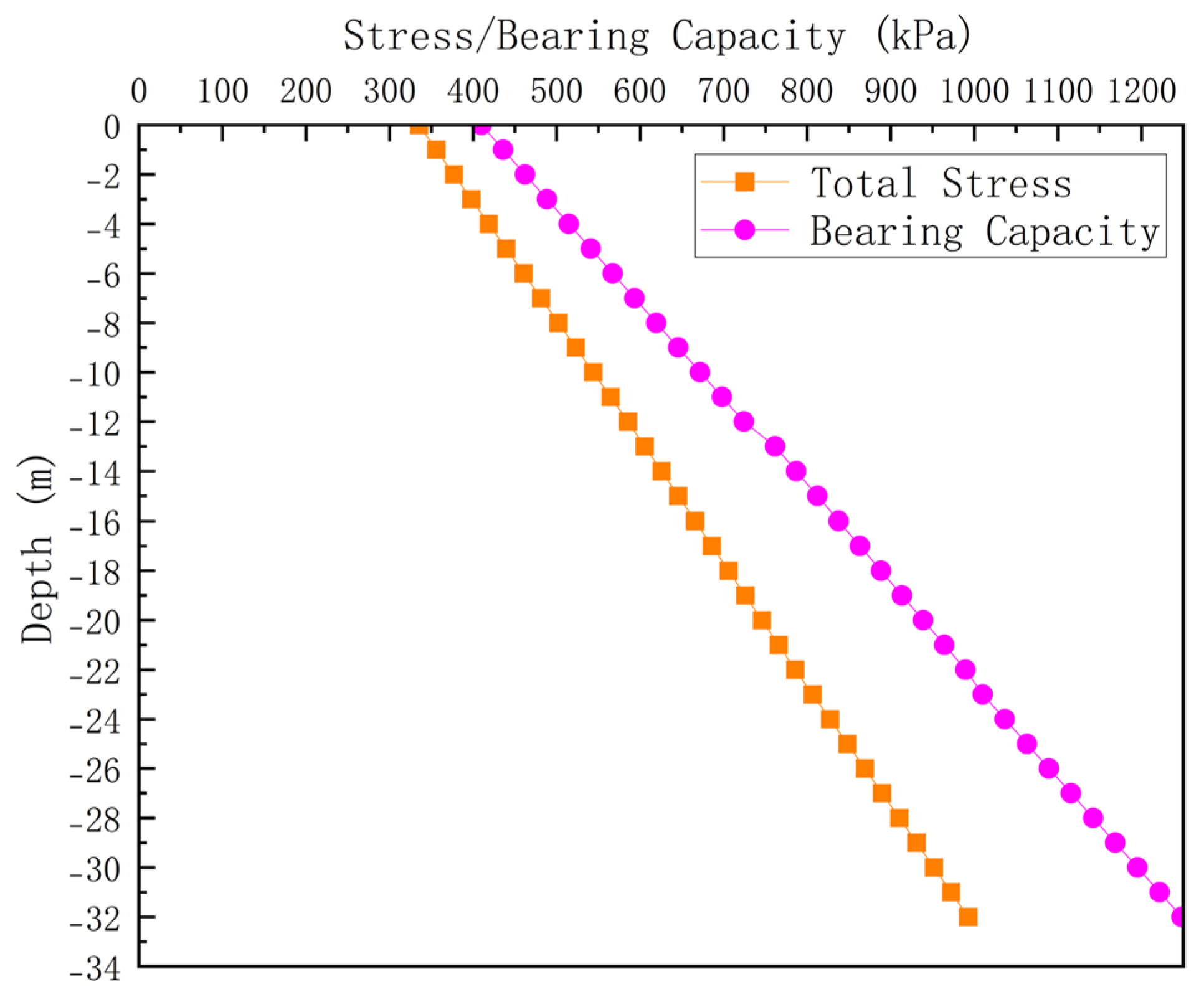
The total stress within the foundation soil layer is the sum of the additional stresses induced by piling operations and the soil’s initial stress. For the cohesive soil foundation, the initial stress distribution is calculated directly from the natural unit weight by using Equation (7). The total stress is then obtained by superimposing the initial stress and the calculated total additional stress, as illustrated by the total stress curve in Figure 11.
Field plate load tests can provide more accurate data and better represent actual engineering conditions. Accordingly, this study adopts the ultimate bearing capacities obtained from the plate load tests (Table 1), and applies depth correction to evaluate the foundation bearing capacity. The depth correction and corresponding coefficients are performed according to the Code for Design of Building Foundation (GB 5007-2011 [24]). The depth correction factor is determined as 1.4. By neglecting the width correction, Equation (9) is obtained. The bearing capacity curve in Figure 12 shows the resulting bearing capacity at the calculation point.
where denotes the characteristic value of the foundation bearing capacity, kPa; represents the depth correction coefficient; represents the unit weight of soil above the calculation point, kN/m3; denotes the thickness of each soil layer above the calculation point, m.
Figure 12.
Comparison of total stress and bearing capacity.
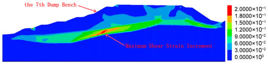
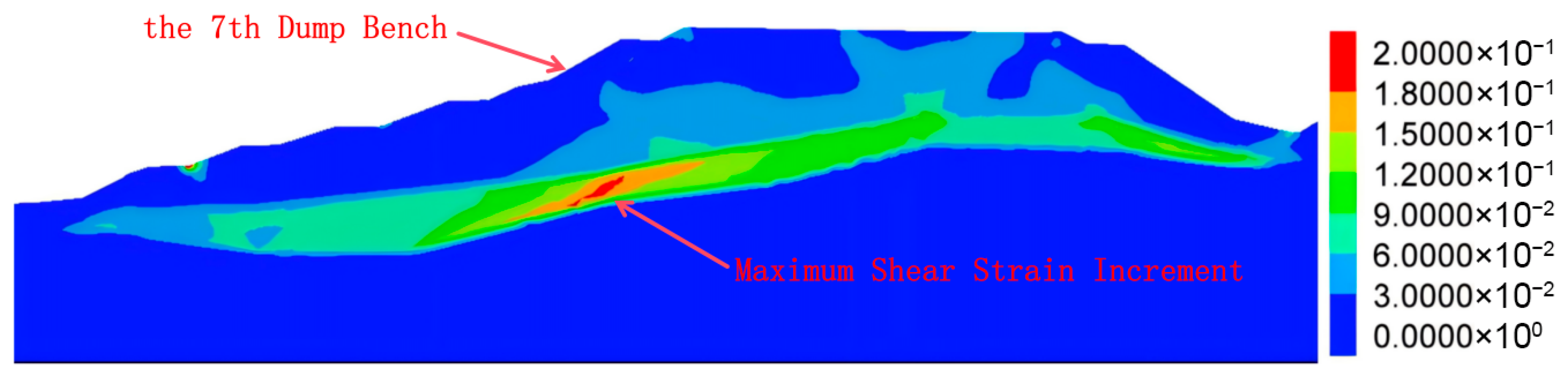
As shown in Figure 12, within the considered soil depth, the foundation bearing capacity beneath the first bench exceeds the corresponding total stress. Using the same method, calculations are performed on the foundation of each slope foot, finding that the bearing capacity of the entire waste dump exceeds the total stress. The ratio of bearing capacity to total stress can be used to define the foundation bearing capacity safety factor. The minimum calculated safety factor occurs at the base of the seventh bench. The overall calculation results for this location are presented in Figure 13. The safety factor of the upper foundation soil is relatively low. By dividing the bearing capacity of the upper soil layer by the corresponding total stress, the safety factor is determined to be 1.23–1.26. This result is generally consistent with the overall slope stability factor obtained from the simulated sliding surface passing through this region. Although numerical simulation from FLAC 3D can obtain the overall stability factor of the waste dump through the strength reduction method, it cannot quantitatively determine the bearing capacity safety factors for different foundation soil layers. In the numerical simulation, the foundation soil layers adopt the Mohr-Coulomb constitutive model and exhibit shear failure under the loading from the waste dump. Therefore, looking at the contour map of the maximum shear strain increment in the foundation soil layers, the location of the maximum value of this increment can be identified as the weakest position in the foundation soil layers after waste dump stacking. The calculated weakest position in the foundation soil layers is at the bottom of the seventh bench, coinciding with the location of the maximum shear strain increment obtained from numerical simulation (Figure 14). The consistency between the calculated and simulated results again confirms the reliability of the proposed calculation method.
Figure 13.
Comparison of total stress and bearing capacity of the foundation at the base of the seventh bench.
Figure 14.
Maximum shear strain increment contour map of the waste dump.
Using the novel calculation method that is based on the Boussinesq equation, the stability factor of the foundation bearing capacity for a waste dump with a height of 125 m is calculated to be 1.23–1.26. The result agrees with both field observations and numerical simulations. Therefore, the maximum allowable dump height exceeds 125 m under the existing slope configuration. Furthermore, a gentler overall slope can result in a greater maximum dump height. However, the maximum ultimate dump height calculated using the aforementioned methods based on Prandtl and Terzaghi is only 20.3 m. These methods fail to consider the interaction between the spatial morphology and the overlying load, neglecting the influence of foundation embedment depth, and disregarding the beneficial effect of the outer slope adjacent to the foundation on the bearing capacity of the foundation. Consequently, the actual dump height is significantly underestimated.
4. Conclusions and Perspectives
4.1. Conclusions
This study provides a comprehensive review and theoretical analysis on the existed methods for calculating the ultimate dump height of waste dumps, which are based on Prandtl’s and Terzaghi’s bearing capacity formulas. Furthermore, a novel calculation method that incorporates slope morphology, stress diffusion, and depth-dependent correction of foundation bearing capacity is proposed. The new calculation method is verified by numerical simulation and engineering case analysis. The conclusions of this study are generated as follows:
- (1)
- Classical methods for calculating the bearing capacity of waste dumps that are based on Prandtl’s and Terzaghi’s foundation formulas, exhibit significant deviations when applied to soft soil foundations. Case analyses indicate that these methods substantially underestimate the ultimate dump height.
- (2)
- The underestimation of the ultimate dump height in classical methods for calculating the bearing capacity of waste dump foundations arises primarily from the direct use of the maximum superstructure load, i.e., P = . These methods fail to account for the load distribution induced by slope morphology and the effects of a large-area uniformly distributed load. Additionally, they neglect the variation in stress at different foundation locations due to diffusion and superposition, as well as the increase in foundation bearing capacity with burial depth.
- (3)
- This study proposes a new calculation method based on the Boussinesq equation and depth correction of bearing capacity. The method addresses two shortcomings of classical calculation approaches: i.e., the insufficient consideration of slope geometry on the upper load distribution, and the influence of embedment depth on bearing capacity. Its reliability is preliminarily validated through case study analysis and numerical simulation.
4.2. Limitations and Future Work
The weak locations in the foundation soil are influenced not only by stress distribution but also by the slope morphology on the outer side and the beneficial effects induced by burial depth. Therefore, the computed results were compared and analyzed with the distribution characteristics of the maximum shear strain increment obtained from the Maximum shear strain increment contour map (see Figure 14). This comparison confirms that the weakest position in the foundation (where the shear strain increment is maximum) is located at the bottom of the seventh dump bench. The simulation results confirm the correctness of the calculation method proposed in this study. Additionally, due to the inherent assumptions of the Boussinesq equation itself, this calculation method inevitably involves a certain degree of error. Further research into computational approaches for anisotropic and non-elastic materials should be performed to better align with the in situ conditions.
It should be noted that a more comprehensive validation, including comparisons with other analytical models or field monitoring data, can further strengthen the robustness of the study. However, due to the limitations of available in situ data and the scope of the present study, such comparisons have not been fully implemented.
Author Contributions
J.M.: conceptualization, methodology, data curation, resources, formal analysis, validation, writing—original draft, writing—review & editing, visualization. J.L.: conceptualization, methodology, investigation, validation, writing—original draft. J.F.: conceptualization, methodology, formal analysis, validation, writing—review & editing. K.Y.: methodology, data curation, formal analysis, writing—original draft. H.Z.: funding acquisition, resources, formal analysis, writing—review & editing, supervision. A.C.: funding acquisition, formal analysis, writing—review & editing, supervision. All authors have read and agreed to the published version of the manuscript.
Funding
This research is supported by the Science and Technology Research and Development Project of Kunming Engineering & Research Institute of Nonferrous Metallurgy Co., Ltd. (KMY-2025-JY-012).
Institutional Review Board Statement
Not applicable.
Informed Consent Statement
Not applicable.
Data Availability Statement
Some or all data that support the findings of this study are available from the corresponding author upon reasonable request.
Conflicts of Interest
Authors Jian Meng and Jiawen Liu were employed by the company Kunming Engineering & Research Institute of Nonferrous Metallurgy Co., Ltd. Jun Fu was employed by the company Kunming Survey and Design Institute Co., Ltd. of China Nonferrous Metals Industry. Han Zhou was employed by the company Kunming Metallurgical Research Institute Co., Ltd. The remaining authors declare that the research was conducted in the absence of any commercial or financial relationships that could be construed as a potential conflict of interest.
References
- Tao, Z.; Zhu, C.; Wang, Y.; Wang, J.; He, M.; Zhang, B. Research on Stability of an Open-Pit Mine Dump with Fiber Optic Monitoring. Geofluids 2018, 2018, 9631706. [Google Scholar] [CrossRef] [Scilit]
- Purhamadani, E.; Bagherpour, R.; Tudeshki, H. Energy consumption in open-pit mining operations relying on reduced energy consumption for haulage using in-pit crusher systems. J. Clean. Prod. 2021, 291, 125228. [Google Scholar] [CrossRef] [Scilit]
- Mikhailov, V.; Koryakov, A.; Mikhailov, G. Ecological risk management in coal mining and processing. J. Min. Sci. 2015, 51, 930–936. [Google Scholar] [CrossRef] [Scilit]
- Xu, D.; Li, X.; Chen, J.; Li, J. Research progress of soil and vegetation restoration technology in open-pit coal mine: A review. Agriculture 2023, 13, 226. [Google Scholar] [CrossRef] [Scilit]
- Pan, Y.; Luo, Y.; Jiang, H. Application research on control technology of weak foundation of mine spoil heap. Min. Res. Dev. 2023, 43, 34–40. [Google Scholar] [CrossRef]
- Hoy, M.; Doan, C.B.; Horpibulsuk, S.; Suddeepong, A.; Udomchai, A.; Buritatum, A.; Chaiwan, A.; Doncommul, P.; Arulrajah, A. Investigation of a large-scale waste dump failure at the Mae Moh mine in Thailand. Eng. Geol. 2024, 329, 107400. [Google Scholar] [CrossRef] [Scilit]
- Jiang, J.; Yang, H.; Cao, L.; Wang, D.; Wang, L.; Jia, Z.; Lu, Y.; Di, S. Bearing capacity calculation of soft foundation of waste dumps—A case of open-pit mine. Front. Earth Sci. 2022, 10, 839659. [Google Scholar] [CrossRef] [Scilit]
- Zhong, S.; Zhang, J. Analysis of the ultimate bearing capacity of the soft foundation of open-pit mine spoil heap. Coal Eng. 2017, 49, 145–148. [Google Scholar]
- Hong, Y.; Du, H.; Chen, M. Bearing Capacity Analysis of the Weak Basement, Progressive Destruction Analysis, and Evaluation of the Dump on an Inclined Strip Section Using the Upper-Limit Method: A Case Study in an Anonymous Open-Cast Coal Mine. Sustainability 2023, 15, 10240. [Google Scholar] [CrossRef] [Scilit]
- Prandtl, L. Über die Härte plastischer Körper. Göttingen Nachrichten Math.-Phys. Kl. 1920, 12, 74–85. [Google Scholar]
- Reissner, H. Zum erddruckproblem. In Proceedings of the 1st International Conference for Applied Mechanics, Delft, The Netherlands, 22–26 April 1924. [Google Scholar]
- Van Baars, S. The inclination and shape factors for the bearing capacity of footings. Soils Found. 2014, 54, 985–992. [Google Scholar] [CrossRef] [Scilit]
- Terzaghi, K. Theoretical Soil Mechanics; John Wiley & Sons: New York, NY, USA, 1943. [Google Scholar]
- Cao, B.; Wang, S.; Song, D.; Du, H.; Guo, W. Investigation on the Deformation Law of Inner Waste Dump Slope in an Open-Pit Coal Mine: A Case Study in Southeast Inner Mongolia of China. Adv. Civ. Eng. 2021, 2021, 9953554. [Google Scholar] [CrossRef] [Scilit]
- Zhang, B.L.; Fan, W. The Influence of Cross Section Geometric Shape on the Slope Stability. Adv. Mater. Res. 2015, 1065, 232–235. [Google Scholar] [CrossRef] [Scilit]
- Xu, M.; Liao, G.; Li, Z.; Zhou, X.; Chen, J.; Li, B.; Sun, Y.; Li, Z.; Xu, Y.; Mao, H. Stability analysis of rock slopes containing faults during excavation using microseismic monitoring and numerical simulation. J. Intell. Constr. 2024, 2, 9180036. [Google Scholar] [CrossRef] [Scilit]
- Shen, H.; Klapperich, H.; Abbas, S.M.; Ibrahim, A. Slope stability analysis based on the integration of GIS and numerical simulation. Autom. Constr. 2012, 26, 46–53. [Google Scholar] [CrossRef] [Scilit]
- Dawson, E.M.; Roth, W.H.; Drescher, A. Slope stability analysis by strength reduction. Geotechnique 1999, 49, 835–840. [Google Scholar] [CrossRef] [Scilit]
- Huang, X.-w.; Mao, X.; Miao, X.; Chen, Z. Study of slope reinforcement force based on FLAC. J. China Univ. Min. Technol. 2006, 16, 123–127. [Google Scholar]
- Schmertmann, J.H. Stress diffusion experiment in sand. J. Geotech. Geoenviron. Eng. 2005, 131, 1–10. [Google Scholar] [CrossRef] [Scilit]
- Boussinesq, J. Application des Potentiels à L’étude de L’équilibre et du Mouvement des Solides Élastiques; Gauthier-Villars Imprimeur-Libraire: Paris, France, 1885. [Google Scholar]
- Sadek, M.; Shahrour, I. Use of the Boussinesq solution in geotechnical and road engineering: Influence of plasticity. Comptes Rendus Mécanique 2007, 335, 516–520. [Google Scholar] [CrossRef] [Scilit]
- Hatami, K.; Miller, G.A.; Esmaili, D. Prototype Reinforced Soil Embankment for Reconstruction of US 62 Slope Failure in Chickasha, OK; Oklahoma Department of Transportation: Oklahoma City, OK, USA, 2015.
- GB 5007-2011; Code for Design of Building Foundation. China Architecture & Building Press: Beijing, China, 2011.

Disclaimer/Publisher’s Note: The statements, opinions and data contained in all publications are solely those of the individual author(s) and contributor(s) and not of MDPI and/or the editor(s). MDPI and/or the editor(s) disclaim responsibility for any injury to people or property resulting from any ideas, methods, instructions or products referred to in the content. |
© 2026 by the authors. Licensee MDPI, Basel, Switzerland. This article is an open access article distributed under the terms and conditions of the Creative Commons Attribution (CC BY) license.