


Abstract
Current structural reliability calculations are typically based on combinations of load pairs. However, there is no consensus on key aspects such as the reference time, the target reliability, or the choice between a stochastic and independent (SC) versus a deterministic and dependent (DC) approach. This article shifts the focus from load–pair combinations to individual load–material pairs and evaluates structural reliability using both the existing Eurocode methodology and a new approach based on 50-year loads and 50-year target reliability as well as the DC framework. The aim is to provide a more consistent and transparent basis for reliability assessment in structural design.
1. Introduction
The terms and assumptions of the Eurocodes [1,2,3,4] apply.
Current structural reliability assessments are generally based on combinations of load pairs. However, there is a lack of consensus in several key areas:
- Reference time may be taken as 50 years [5], 5 years [6,7,8], or one year [9,10].
- Reference reliability could refer to the 50-year reliability [5,6,7,8,10] or a modified one-year reliability [9].
- Load combination may be deterministic, as in combination (8.12), Equation (4), or stochastic, as in combinations (8.13), Equation (5), and (8.14), Equation (6).
- The method of reliability calculation can follow either the SC [1,2,3,4,6,7,8,9,10,11,12,13,14,15,16,17,18,19,20,21,22,23,24,25,26,27,28,29,30,31,32] or DC approach [5,33,34,35,36,37].
The SC approach treats loads as random variables and combines them using probabilistic methods that reflect their independent and variable nature. This results in a reduced combined effect due to negligible probability for simultaneous high loads, typically implemented by applying implicit combination factors through two separate partial safety factors to permanent loads or by applying an explicit combination factor ψ in two variable loads.
By contrast, the DC approach also acknowledges the randomness of loads but combines them deterministically. The loads are summed directly without any reduction, implying full correlation in the load combination, even though the actual loads are uncorrelated. Correlation may arise from multiple sources. In particular, constraints on resistance can induce correlation. Once the first load is selected, the second load is automatically determined, as it is equal to the resistance minus the first load.
In the authors’ view, the DC approach provides a more realistic and transparent framework for reliability assessment. Supporting arguments are presented in this article, and results for both SC and DC methods are applied and compared.
This article further shifts the focus from load combinations to the treatment of individual loads, evaluating structural reliability using both the current Eurocode methodology and a proposed alternative based on 50-year loads, 50-year reliability, the DC framework and independent load–material pairs.
In the present study, load combinations are assumed to be dependent. In contrast, the Eurocodes treat load combinations primarily as independent, although certain cases are dependent. Semi-dependent approaches are not applied and are disregarded here, too.
This paper is organized as follows. Section 1 reviews the background and outlines the novelty of the study. Section 2 describes the materials and methods used. Section 3 presents the results and the arguments for the DC. Section 4 discusses implications. Section 5 concludes the paper.
1.1. Background
The authors’ investigation into load combinations began two decades ago, coinciding with the initial publication of the Eurocodes [1]. The triggering observation was a structural abnormality: the codes appeared to contradict deterministic mechanics by applying two different safety factors to permanent loads. For example, in combination rule (8.14) the Eurocode specifies a partial factor of 1.15 for the permanent load and 1.5 for the variable load. However, in a separate combination rule, the permanent load is assigned a higher factor of 1.35, while the variable load is omitted. This leads to an unexpected result: the design load remains unchanged, whether only a permanent load is present or a variable load—up to 12% of the total load—is added. In effect, adding a variable load does not increase the load. This suggests that a portion of the load is effectively not accounted for, leading to a decrease in calculated reliability. Such outcomes raise questions about the internal consistency of the load combination rules and highlight the need to re-examine the assumptions behind them.
The authors deduced that, according to the fundamental principles of mechanics, the combined distribution of permanent and variable loads must intersect at the crossing point of their individual distributions. In the initial phase of the research, the combined load distribution was calculated using the convolution integral, which accurately represents the sum of two independent random variables. To ensure mechanical consistency, the resulting distribution was adjusted by fixing the deviation such that it passed through the intersection point of the individual load distributions. This key insight was first presented concisely in [33] and elaborated in [34], where the key argument for the DC approach was that the SC approach contradicts fundamental mechanics.
Subsequently, the authors discovered that the DC can be obtained more directly—either by summing the load distributions using their fractiles or by applying a special recursive process, i.e., Equation (3). In Monte Carlo (MC) simulations, this approach requires only a single seed number; a group effect was introduced which further supports the DC approach. A proposal was made for new Eurocodes in [36], and a proposal to remove the combination factors in [37]. However, these arguments and proposals were not convincing, and the DC approach has not gained significant recognition among code developers, even though the traditional SC approach introduces shortcomings—particularly due to its inherent load reduction. These shortcomings include:
- The SC approach results in a reductiosn of combined loads, leading to safety factors and reliability levels that are 0–10% lower than those derived from a deterministic approach. Additionally, Eurocode combination rules such as (8.13) and (8.14), which apply two factors to permanent loads, introduce a further load reduction of up to 10%. Compounding this, current reliability calculations are often based on a 5-year reference time rather than 50 years, leading to a reduction of up to 20% in the assessed variable load.
- The load reduction inherent in SC requires a separation between ultimate limit state (ULS) and serviceability limit state (SLS) design. Specifically, load reductions are applied in ULS but not in SLS, creating a demand for the partial safety factor design framework.
- The use of SC introduces difficulties in determining safety factors and reliability calculation, and there is no clear consensus on the appropriate methodology.
This article presents new critical arguments for the DC approach and the independent load–material scheme. The authors therefore contend that it establishes a fundamental basis for structural design.
1.2. Problem and Target
The current paradigm for structural load combination relies on the SC and combination of load pairs without a consensus on the calculation process. When the focus is shifted to individual loads, the article explains that the reliability calculation should be based on the DC, 50-year loads and 50-year target reliability.
1.3. Novelty
The authors previously presented four arguments supporting the use of the DC approach, which are summarized here for clarity and consistency [5,33,34,35,36,37].
- The principles of physics and deterministic mechanics should govern structural design. Accordingly, the distribution of combined loads should result from the intersection of the partial load distributions. The SC approach combines loads based on occurrence, thereby violating fundamental physical principles.
- The variable load virtually always acts simultaneously with several permanent loads. This means that the load distributions are not independent; therefore, the basic assumption underlying the SC approach is not valid.
- A load combination is a unique event, and therefore a single seed number should be used in the MC simulation.
- Some loads, for example, imposed loads in multi-story buildings, are correlated, as they represent sub-loads of the total load acting on the building.
This article introduces four new arguments for the DC, as follows:
- Shift from load pairs to individual load–material pairs: Traditional structural reliability assessments are based on combinations of load pairs. This article shifts the focus to independent load–material pairs, which supports the adoption of the DC approach. The combination of load pairs is also addressed, and it is demonstrated that their combination is dependent, too.
- The SC approach applies a reduction to combined loads based on the assumed low probability of simultaneous extreme loads. However, within the load-combination framework, structural resistance defines the upper bound for the loads that can be combined. When one load reaches its maximum or near-maximum value, any accompanying load must be zero or nearly zero. From a resistance perspective, the combination of two extreme loads is therefore not feasible, and consequently, the simultaneous occurrence of extreme high loads does not occur.
- The design equation establishes a constraint for the combination: Structural design normally aims for full utilization of resistance, meaning that the design equation (Equation (4)) is treated as equality. This imposes a constraint on the load combination leading to DC.
- Unified treatment of all load combinations as dependent: While the authors previously showed that most structural loads are combined dependently—except for intermittent variable loads such as wind and imposed load—this article demonstrates that even intermittent variable loads are effectively combined dependently, and no combination factors ψ should be applied [37].
1.4. Review
Structural design codes and the related literature can be divided into three levels of accuracy: I, II, and III [3,11,12,13,14,15,16,17,18,19,20,21,22,23,24,25,26,27,28,29,30,31,32].
- Level I represents the traditional approach, based on historical and empirical methods, with deterministic load combinations.
- Level II forms the basis of the current Eurocodes, employing the SC and the First-Order Reliability Method (FORM). This semi-probabilistic method assumes independent reliability calculation, where load reduction is applied by the low probability that the extreme values of both permanent and variable loads occur simultaneously. This reduction is introduced via sensitivity factors, denoted αE and αR, which lower the effective target reliability and lead to reduced design loads. The idea of this load combination was presented first in [27], where loads were assumed to be pulses of varying time and interval. This load combination leads to virtually the same outcome as Equation (2). Later, Turkstra [28] introduced a load combination rule for multiple loads by designating each load as the leading load in succession, applying no reduction factor to it, while treating other loads as accompanying loads with a reduction factor without further reductions, i.e., combining the accompanying loads dependently. This concept was incorporated into the Eurocodes and yields outcomes that are virtually the same as those produced by Equation (2). In practice, the reliability is currently calculated in three alternative ways, which apply the SC and differ regarding either the reference reliability or time. In all these safety factor calculation options, the load combination may be deterministic like in rule (8.12) or stochastic like in rules (8.13) and (8.14) in the Eurocodes.
- Level III involves a fully probabilistic approach and represents the most accurate modelling level. While not yet adopted in any structural design code, it is permitted as an option in the updated Eurocodes [2]. The approach proposed in this article is based on a fully probabilistic model consistent with Level III accuracy.
2. Materials and Methods
The calculations are made for the Eurocodes [1,2]. The design point is set at unity at the SLS and at the ULS. This means that, in the SLS, the 0.5 fractile of the permanent load distribution, the 0.98 fractile of the one-year variable load distribution, and the 0.05 fractile of the resistance distribution are all set equal to unity. In the ULS, the load distributions are divided by partial safety factors, while the resistance distributions are multiplied by partial safety factors. Basic design cases in normal structural design are addressed using linear elastic analysis, with permanent and variable loads for three materials: steel, timber, and concrete. Special effects such as geometric imperfections, dynamic behavior, nonlinearity, and stability are not considered.
2.1. Uncertainty
Uncertainty is a challenging aspect of code calibration and reliability calculation. Currently, these effects are accounted for by modifying the load or resistance distributions using the SC approach. In the authors’ opinion, the DC approach is more appropriate; further valid data for the necessary parameters are lacking. This article concludes that the current Eurocode safety factors do not achieve the reliability target of β50 = 3.8; when uncertainties are taken into account, this discrepancy becomes even more pronounced. Therefore, uncertainty is disregarded here, under the assumption that the load and resistance parameters, as well as the target reliability, are carefully chosen to justify this simplification.
2.2. Permanent Load
The permanent load distribution is normal, the cumulative distribution is , where is the mean and is the standard deviation, and the density distribution is , = 1, = 0.1, VG = 0.1 [1,2].
2.3. Variable Load
The variable load distribution is assumed to be the Gumbel distribution, with cumulative distribution and density distribution where the one-year parameters are = 0.491, = 0.196, VQ = 0.4. When the calculation is based on a time other than one year, the distribution is , where (years) is the time for which the calculation is made [1,2].
2.4. Materials
The material resistance distribution is assumed to be the log-normal distribution, with the cumulative distribution and density distribution corresponding to parameters given in Table 1 [38,39,40].
Table 1.
The parameters of the three examined materials: steel, timber, and concrete. VM = coefficient of variation; μM = mean; σM = deviation; γM = material safety factor.
2.5. Basic Equations
The reliability calculation utilizes three equations. The safety factor calculation procedure is explained in detail [5,35,36,37,38] and summarized here. When a load L, with the cumulative distribution and the safety factor , strikes a material with the resistance cumulative distribution and density distribution , the equation to calculate the safety factor γL or γM or the failure probability Pf may be written in multiple forms, e.g., [5,35,36,37,38]
When the load comprises the permanent and variable load and the variable load proportion is α in relation to the total load α = , the cumulative distribution of the SC is calculated as given by [5,35,36,37,38]
where is the cumulative distribution of the permanent load and is the density distribution of the variable load.
The cumulative distribution of the DC is calculated by [5,35,36,37,38]
This recursive equation, written in Mathcad notation, implies that the distributions are aggregated fractile by fractile.
3. Results
This section presents arguments for deterministic reliability calculation and load combination.
3.1. Independent Loads Induce Independent Effects
It is widely accepted that structural loads are random and that various load pairs are statistically independent. From this, it is commonly concluded that the load combination is also treated as independent, leading to a reduction in combined load effects—based on the probability of simultaneous high loads being low. However, the opposite conclusion should be drawn: When loads are independent and stochastic, they should be combined deterministically and additively—not reduced. The load reduction applied in the SC approach introduces correlation, since the effect of one load depends on whether the other is present. This violates the very assumption of independence, revealing a critical inconsistency in the SC methodology.
To illustrate this concept, assume load L1 produces an effect e1 in the structure; it is clear that other loads may have no effect on e1, and an independent load L2 produces effect e2. If L1 and L2 are statistically independent, there is no justification for reducing their combined effect—the total effect is simply: e1 + e2. Applying a reduction factor in this case would imply statistical dependence, contradicting the assumption of independence.
The current axioms of probability theory, when applied to independent loads, are based on a flawed two-step process in which one load is selected first and the other subsequently. This procedure leads to a low probability of simultaneous occurrence of independent extreme loads and to the dominant SC approach. In this approach, when and act individually, producing effects and , the effects in the combination are typically less than and . This contradicts fundamental principles of mechanics and logical reasoning. Once the effect of the first load is determined, the second load cannot alter the effect of the first load.
In contrast, load combination is properly treated as a one-step process, in which both loads are selected simultaneously, resulting in the DC approach.
If there are more than two loads, the effects of all of them are additive, and no reductions like combination factors ψ are applied. The DC approach is more aligned with the true stochastic nature of structural loads, and it avoids the inconsistencies introduced by artificial load reduction. Moreover, it allows for a simpler and more transparent design framework. Nonetheless, for comparison and completeness, this article presents results for both DC and SC approaches. This argument for the DC based on single and independent loads is most obvious and convincing. The current theory examines load pairs. However, load pairs are also combined deterministically, as explained next.
3.2. High Loads Never Occur Simultaneously in the Determining Load Combination
The SC load combination includes a reduction based on the assumption that the simultaneous occurrence of multiple extreme loads has negligible probability. The purpose of the following reasoning is to demonstrate that multiple extreme loads never occur simultaneously, as the resistance defines the admissible domain for load combinations. Consequently, SC’s argument regarding the negligible occurrence of high loads is not valid.
A fundamental principle of structural design codes is that the probability of failure should be uniform across all load combinations. Accordingly, characteristic values and partial safety factors are calibrated so that, for each load–resistance pair, the resulting design load corresponds to the same target reliability. By appropriately selecting characteristic values and safety factors, the corresponding design resistances are likewise brought to a consistent level. Such calibration is feasible, as demonstrated in [36] for permanent load–timber and variable load–timber combinations. Although this principle is not fully realized in codes, owing to approximations and simplifications in the calibration of partial safety factors and characteristic values, it is nevertheless satisfied with sufficient accuracy for the purposes of the present discussion.
Load combinations are applied only to feasible loads—those below the actual resistance of the structure. Resistance therefore defines the upper load limit and the load domain that forms the basis for analyzing load combinations.
It follows that the extreme design load corresponding to the target reliability is obtained when a single load acts alone. In other words, when an individual design load is applied to a structure, it induces a stress d with reliability . When multiple loads—for example, and —act simultaneously, the magnitude of each load is lower than , with each causing stress less than d regardless of whether the SC or DC approach is used. That is, extreme loads never occur simultaneously within a load combination, and the SC argument assuming negligible simultaneous extremes is therefore not valid.
Regarding SC versus DC and load magnitudes, two representative cases can be identified: (A) the first load is close to its maximum value, in which case the second load must be close to zero; and (B) both loads take, approximately, their mean values. In both cases, no load reduction is applied in the determining load combination, regardless of whether the SC approach (Equation (2)) or the DC approach (Equation (3)) is applied.
In the reasoning above, the probability distribution of a load between zero and its maximum value is irrelevant for the purpose of load combination. This implies that all loads—including two intermittent loads such as imposed load and wind load—should be combined dependently and without the use of combination factors ψ. In this particular case, however, load reduction may still be justified based on intermittency rather than load combination. This issue is not discussed further here, as it is both complex and of secondary importance to the overall load combination framework.
3.3. The Design Equation Establishes a Constraint for the Combination
Structural design normally aims for full the utilization of resistance, meaning that the design equation (Equation (4)) is treated as equality. This imposes a constraint on the load combination: if one load increases, the other must decrease accordingly. This constraint applies both to the summation of actual design loads and to the combination of the corresponding load distributions. In other words, the constraint induces correlation within the combination, making the load combination dependent.
3.4. Physics
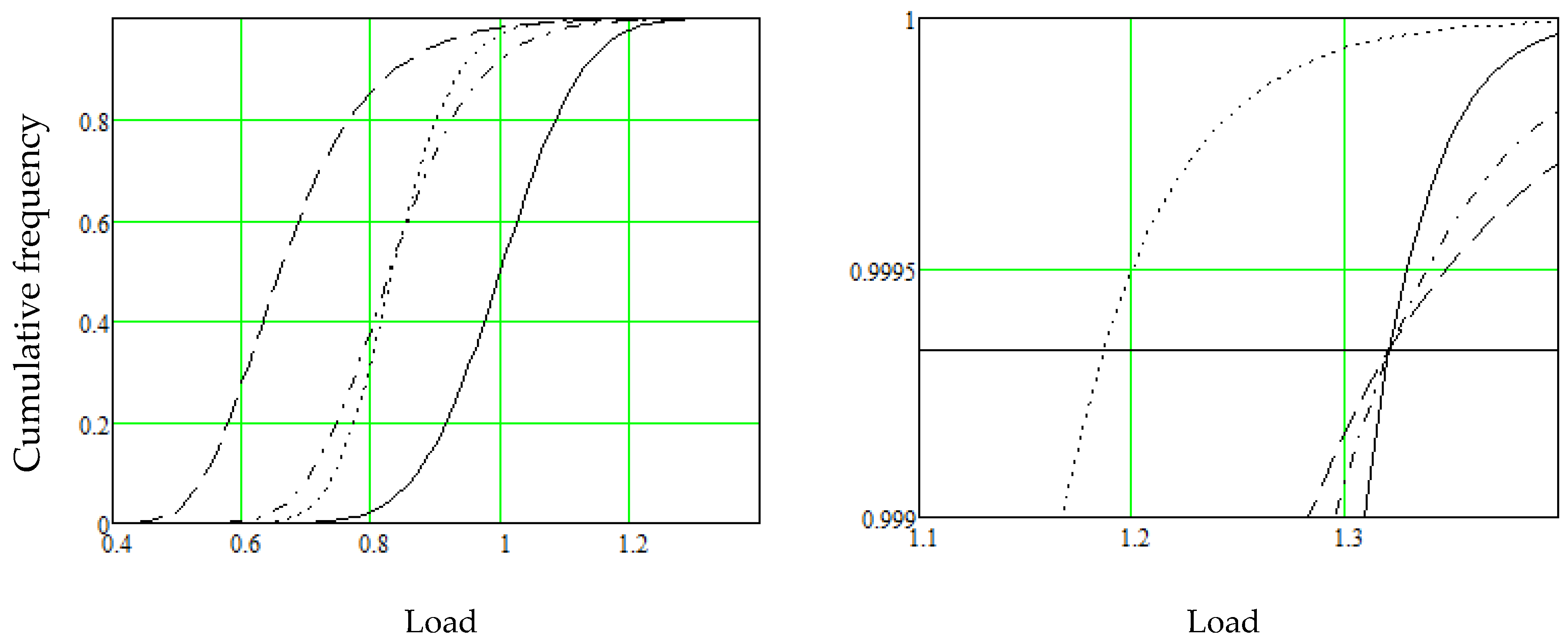
Assume a structure is loaded by load one L1 and load two L2. When the loads act alone, their distributions cross. At the crossing point, the loads act equally on the structure and assume that the structure fails at this crossing point load L and failure probability P, equally due to L1 or L2. The crossing point denotes a load combination of 50% + 50%. According to physics, the structure also fails under this combined load, with probability P. Thus, the combination load distribution crosses the crossing point of the single loads. This is demonstrated in Figure 1. The solid line shows the permanent load, μG = 1, σG = 0.1. This load is 1.32 at the target reliability β1 = 4.2, i.e., Pf50 = 1/1499, Sf50 = 0.99933. The dashed line shows the 50-year variable load with one-year parameters, μQ = 0.31, σQ = 0.12, which has the same 50-year load at the same reliability. The dash-dotted line shows that the dependent combination load distribution 50% + 50% crosses the crossing point of single loads. The dotted line shows the independent combination load; it does not cross the crossing point. The load value at the target reliability is 1.19, i.e., 10% less, i.e., the SC results in load vanish. The loads are combined in this case in proportions of 50% + 50%; however, the dependent combination crosses the crossing point in all proportions. The DC fulfils the criterion explained above, and the SC does not.
Figure 1.
(Left Figure): Solid line, permanent load; dashed line, variable load; dash-dotted line, DC; dotted line, SC. Horizontal solid line, the target survival probability St,50 = 0.99933; (Right Figure): magnification of a region on Left Figure.
The example above applies to the combination of permanent load and variable load. However, this argument for the DC applies to all load combinations, e.g., combinations of two variable loads.
3.5. A Load Combination Is a Unique Event
The target reliability defines how many proportions (events, incidents) the failure domain is divided into to result in one failure. In the Eurocodes, with β50 = 3.8, the failure domain is divided into 15,000 proportions—meaning, for example, that one failure is allowed in 15,000 structures, with one failure due to the permanent load. In the MC simulation, one seed number is used. When two loads act together, reliability remains the same as for individual loads, so the failure domain is still divided into 15,000 proportions, including a pair of two loads. There is one division only; therefore, in the MC simulation, one seed number is used for this as well, meaning that one failure is allowed in 15,000 load pairs in 50 years, which results in the DC. In the SC, however, two seed numbers are used: one seed number for one load including 15,000 proportions and another seed number for the other load including 15,000 proportions. As a result, the total number of proportions, including one failure, would incorrectly become 15,0002. The outcome is an improbable simultaneous occurrence of high values and an artificial load reduction. So, one seed number must be applied for load combinations resulting in the DC.
3.6. The Variable Load Strikes Simultaneously with Multiple Permanent Loads
Assume that a roof has n similar girders, equally spaced apart, designed for 50 years in a single process—i.e., one design and one design load combination apply to all girders. Each girder i has a different permanent load gi, which consists of the self-weight of the girder plus the weight of the roof structure over the area corresponding to the girder’s length and spacing. One of the n girders has the maximum permanent load gmax. In this case, the variable load is assumed to be a uniform layer of snow distributed evenly over the roof, as prescribed by building codes and as typically observed in reality. Each year j of the service life has a different variable load qj,i affecting girder i, which is the actual snow load multiplied by the impact area of girder i. The maximum snow load qmax occurs in one year j during the service life. This load qmax affects all the girders of the roof simultaneously, including the one with the maximum permanent load gmax. Consequently, the maximum loads gmax and qmax occur simultaneously, and the maximum combination load can be approximated as = + . By analogous reasoning, the next greatest loads, gmax−1 and qmax−1, are also simultaneous, and the second-largest combination load is = + . Thus, full correlation exists between the loads in the combination, even though any single pair of G and Q is independent. The assumption of the SC incorrectly implies that the probability of the maximum loads gmax and qmax occurring simultaneously relies on the assumption 1/50 when it is close to 1. The example above demonstrates that the maximum variable load qmax and the maximum permanent load gmax occur simultaneously, supporting the use of the DC.
This argument can be extended to the combination of permanent loads and all variable loads. The design domain in the Eurocodes β50 = 3.8 includes 15,000 failure scenarios, typically corresponding to an area of about 1 km2. Only one failure is permitted in this area over a 50-year period. It is reasonable to assume that the variable load is always uniform over this small area. Therefore, the permanent load and the variable load must be combined dependently, following the same reasoning as explained above.
The SC is based on the combination of individual load pairs, where one permanent load is randomly selected and combined with a random variable load. One might argue that the reasoning above regarding the group effect is irrelevant. However, even though the loads are combined in individual pairs, the DC should still be applied, as the distributions of permanent loads and variable loads are fully correlated, as explained above.
3.7. Correlated Loads
Imposed loads in multi-story buildings are correlated, as they are sub-loads of the total imposed load in the building. Due to this correlation, these loads follow the DC, as explained in more detail in [37].
3.8. Secondary Arguments
There are secondary arguments for the DC:
- The SC is based only on probabilistic assumption disregarding mechanics. Although it may seem obvious, no proof or supporting arguments are provided for its validity.
- The basic assumption of the SC is that adjacent load pairs are independent. However, adjacent load pairs of permanent and variable loads are not truly independent—while the permanent loads in adjacent load pairs are independent, the variable loads are not, as adjacent load pairs typically have the same variable load.
- The concept of independent load combination is not applied consistently in design codes. For example, although the permanent loads of different stories in multi-story buildings are independent, the DC approach is still applied. Similarly, when a permanent load consists of multiple layers, the current interpretation would imply the use of the SC approach; however, the DC approach is applied in the codes.
- A consensus method for safety factor setting and reliability calculation does not exist. For instance, the Eurocodes include three combination rules, safety factors vary between countries, and various reliability calculation methods produce different results, apparently due to inconsistencies in the SC.
4. Discussion
The DC vs. the SC is realized differently in the load combination, in the reliability calculation, and in target reliability setting; these issues are discussed in this section.
4.1. Load Combination of the Design Loads
The load combination applies to the summation of loads G and Q in the basic design equation:
where G, Q and M are deterministic characteristic values. There is no randomness in this summation; therefore, the DC should be used.
The Eurocodes include three load combination rules (8.12), (8.13) and (8.14) [1,2] for the design load Fd calculation. Rule (8.12) is
where α is the proportion of the variable load. It is deterministic and follows the rules of mechanics and applies to the DC.
Rule (8.13) is
and rule (814) is
These rules are independent and apply the SC.
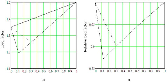
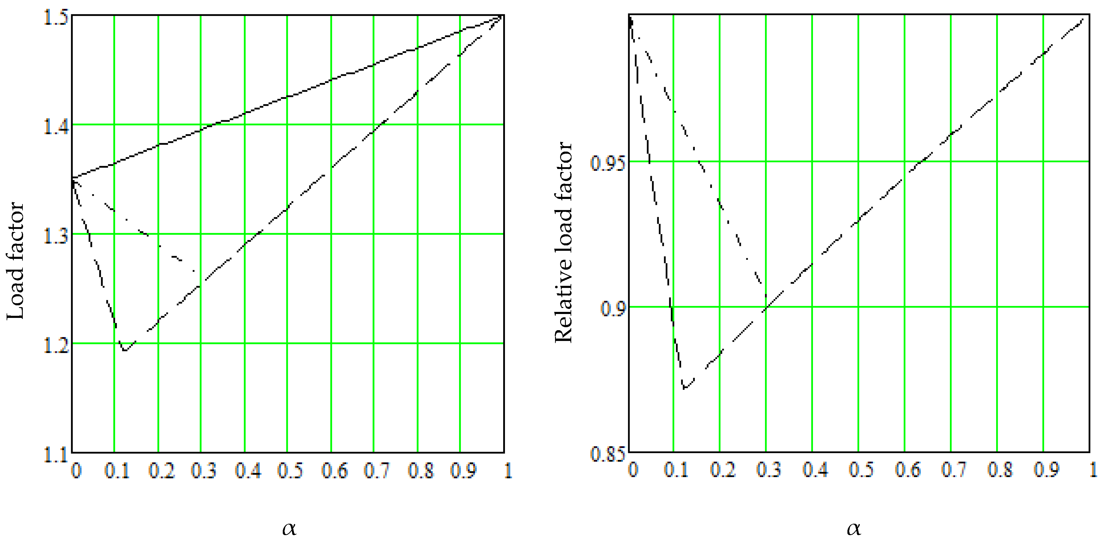
Figure 2, on the left, shows load factors for rules (8.12), (8.13), and (8.14) and on the right the relative load factors in comparison to rule (8.12) as a function of the variable load proportion α. The solid line represents rule (8.12), the dashed-dotted line represents rule (8.13), and the dashed line represents rule (8.14). We find that rules (8.13) and (8.14) indicate a load reduction of up to 13% compared to the dependent combination (8.12). Rules (8.13) and (8.14) are incorrect from a summation perspective but are still implemented because rule (8.12) is considered excessively conservative. This belief stems from the assumption that the current reliability calculation does not account for the load reduction necessary in the SC. However, the current reliability calculation includes a load reduction as explained next.
Figure 2.
(Left Figure): load factors as a function of the variable load proportion α: solid line, rule (8.12); dashed line, rule (8.14); dash-dotted line, rule (8.13). (Right Figure): corresponding relative load factors regarding (8.12).
4.2. Load Combination in the Reliability Calculation
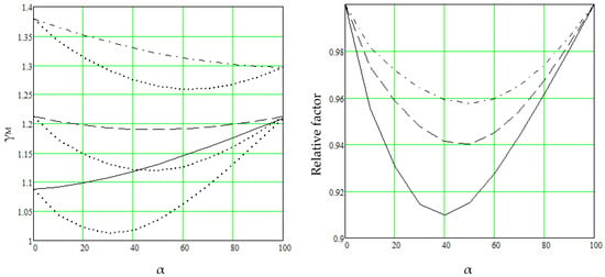
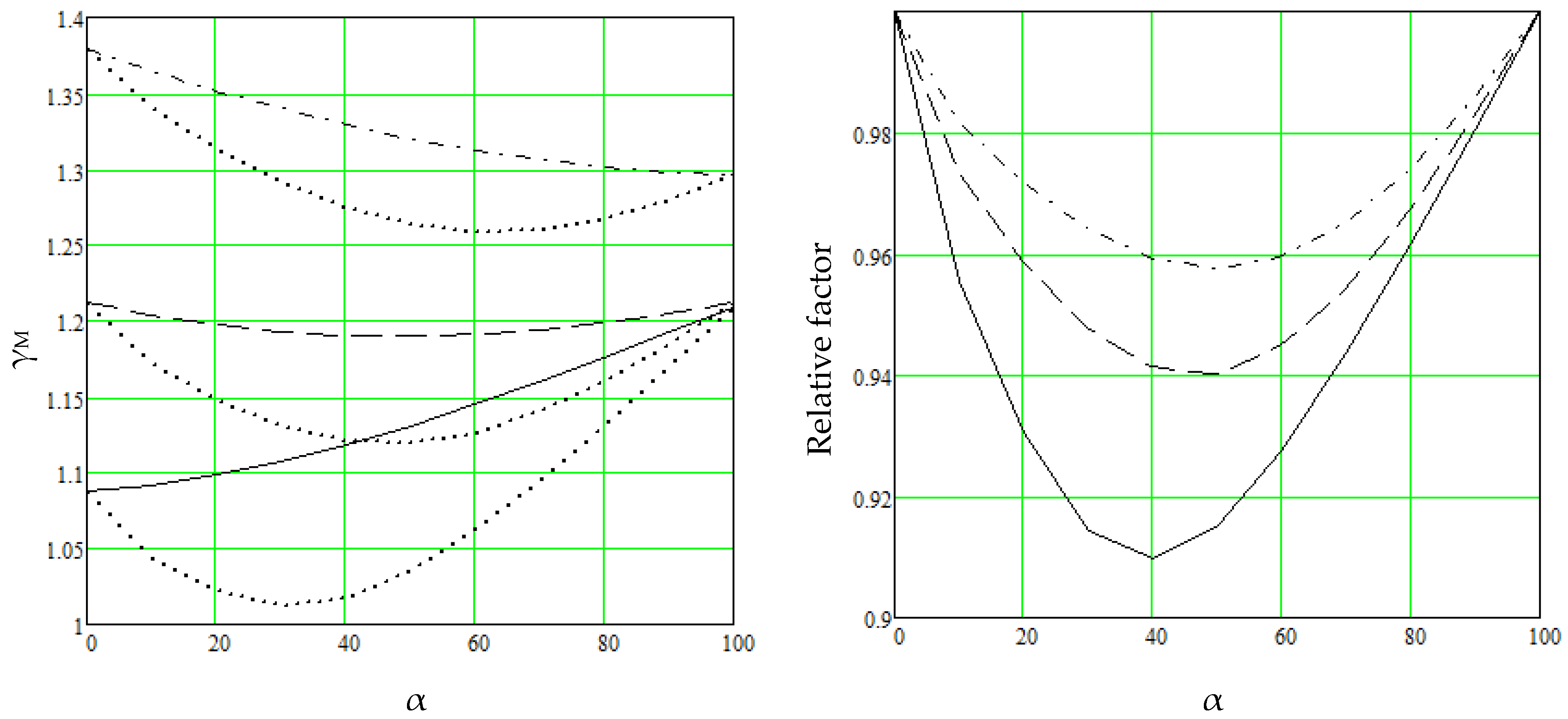
Figure 3, on the left, shows the material safety factors calculated using the DC and SC based on the authors’ Eurocode proposal β50 = 3.2, = = 1.2; the characteristic load of the variable load is 32% higher than the one-year 0.98 fractile [36] as function of the variable load proportion α (solid line steel, DC; dashed line timber, DC; and dash-dotted line concrete, DC). The DC curves in Figure 3 on the left are generated by combining two loads. Although they appear nearly linear, they should, in fact, form straight lines under the DC approach when reliability is evaluated using independent load–material pairs. The slight deviations from linearity arise from distributional anomalies in the probabilistic combination of the two loads. Dotted lines denote the SC values. Figure 3, on the right, presents relative factors regarding the DC.
Figure 3.
(Left Figure) shows material factors: solid line, DC, steel; dashed line, DC, timber; dash-dotted line, concrete, DC; dotted lines show the corresponding SC material factors. (Right Figure): the SC material factors in comparison to the DC ones.
The load reduction varies across different materials, being largest in steel and smallest in concrete. The load reduction in the load combination is slightly greater than in the safety factor calculation. Figure 3 shows that the reliability calculation using the SC includes a load reduction. If the SC is also applied in the load combination, a double reduction is obtained. However, the total reduction in the codes is not too large, as the calculations in these respects are correct for single loads when the reliability is calculated without a reduction in the target reliability.
4.3. Safety Factor for Timber
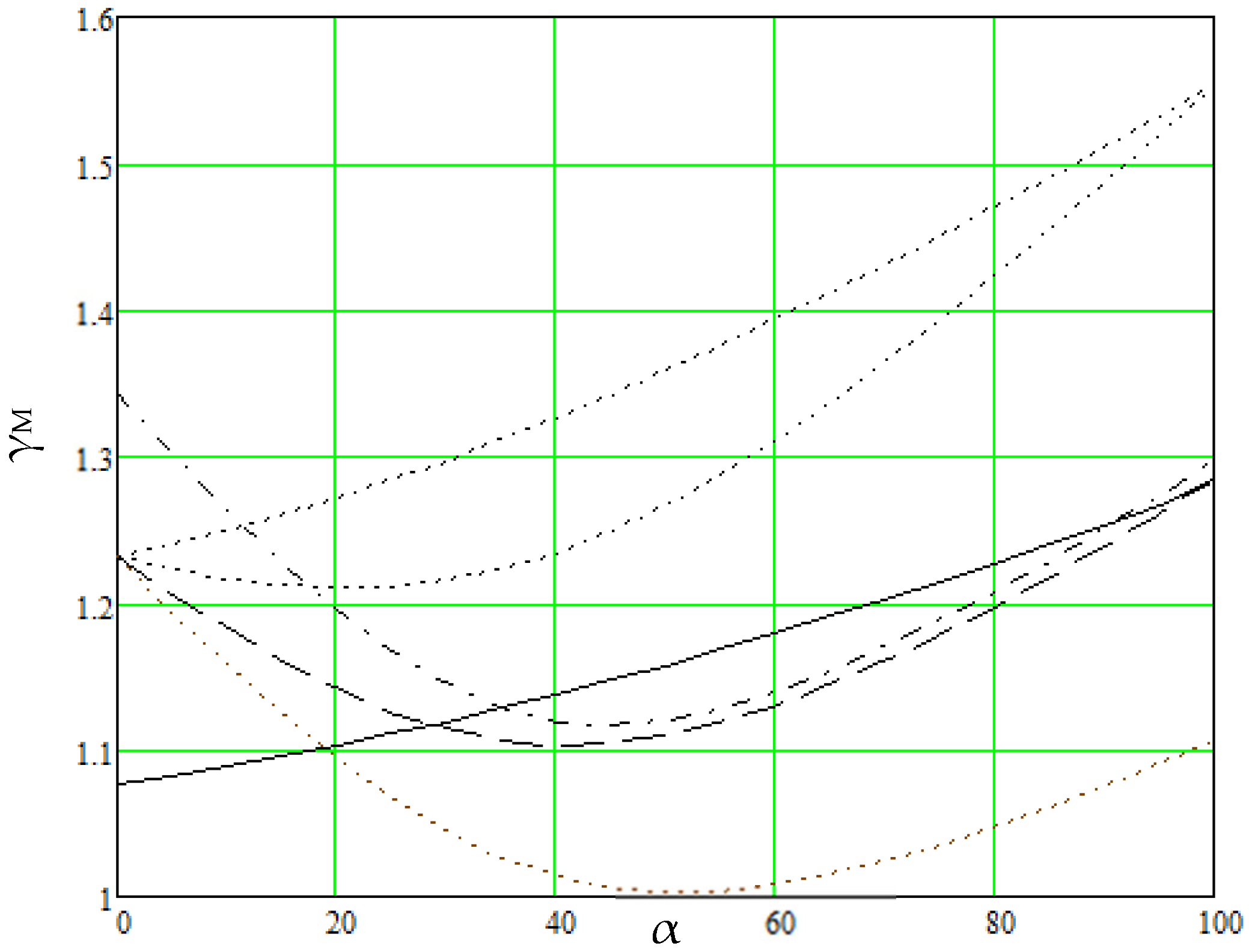
To demonstrate the various calculation methods and their differences, the safety factors for timber are given using six approaches for the Eurocodes β50 = 3.8, = 1.35, = 1.5, rule (8.12). The results are presented in Figure 4.
Figure 4.
Material safety factors for timber calculated using six options: 1: DC, β50 = 3.2, 50-year loads, solid line; 2: SC, β50 = 3.8, 5-year loads, dashed line; 3: β1 = 0.9 × 4.7 ≈ 4.2, one-year loads, dash-dotted line; 4: β50 = 3.8, one-year loads, lowest dotted line; 5: DC, β50 = 3.8, 50-year loads, highest dotted line; 6: SC, β50 = 3.8, 50-year loads, mid-level dotted line.
Option 1—The authors’ proposed approach, DC, β50 = 3.2, 50-year loads, uses a reduced reliability compared to the Eurocode target, β50 = 3.8 because current material factors do not consistently achieve β50 = 3.8 for variable loads (solid line). This view is supported by [41].
Option 2—Gulvanessian et al. [6,7,8], SC, β50 = 3.8, 5-year loads, represents the most plausible approach for current Eurocode reliability calculation (dashed line).
Option 3—Köhler et al. [9], SC, β1 = 0.9 × 4.7 ≈ 4.2, one-year loads, although applied in some contexts, results in the same outcome for variable loads as option 2. This method leads to unrealistically high safety factors for permanent loads; permanent load reliability is independent of time, and this reliability need not be higher than the Eurocode target, β50 = 3.8 (dash-dotted line).
Option 4—Ranta-Maunus et al. [10], SC, β50 = 3.8, one-year loads: this method results in unrealistically low safety factors for variable loads (lowest dotted line).
Option 5—Eurocode approach, DC, β50 = 3.8, 50-year loads: in the authors’ opinion, this is the correct calculation for β50 = 3.8, as it results in much higher safety factors than current code values (1.55 > 1.3 for variable loads) (highest dotted line).
Option 6—Same as option five but SC reliability calculation is applied (mid-level dotted line).
4.4. The Safety Factors of the Eurocodes
The Eurocodes are fundamentally based on the SC approach. Within this framework, load reduction is consistently applied in reliability calculations and in load combinations, as specified in rules (8.13) and (8.14), where two different partial factors for permanent loads are employed. These reductions affect only combination loads—i.e., when both permanent and variable loads contribute significantly. No load reduction is applied for single-load scenarios. As a result, the overall effect of these two reductions is relatively minor. However, a third form of reduction—lowering the target reliability index—has a much greater impact. In current practice, the target reliability for variable loads is calculated using a 5-year reference period, while the actual design life is 50 years. This mismatch results in material factors for variable loads that do not align with the intended Eurocode target reliability of β50 = 3.8. Conversely, the material factors match well for permanent loads, creating a systemic imbalance between the safety of permanent and variable actions.
An alternative SC approach [10] is sometimes applied using a one-year reference period, where the one-year target reliability β0 = 4.7 is reduced by 0.9, yielding β1 ≈ 4.2. While this method produces results comparable to the 5-year approach for variable loads, it leads to higher safety factors for permanent loads.
In the authors’ view, the reliability assessment should consistently use a 50-year reference period and target a 50-year reliability index. When this is done, the actual reliability provided by the Eurocodes is below the nominal target of β50 = 3.8, as confirmed in [41]. According to the authors’ ongoing studies and articles in review, the actual reliability is approximately β50 = 3.2, except in the case of steel, where the factor γM = 1.0 appears to be insufficient for variable loads VQ = 0.4. Recognizing β50 = 3.2 as the actual achieved reliability and recalibrating material safety factors accordingly using the DC approach can yield significant material savings, as demonstrated in previous studies [36].
The Direct Design Method is a recent development in structural engineering, in which design is based directly on statistical distributions of loads and resistances, without applying code-prescribed safety factors [23]. The SC approach is used, resulting in load reductions of up to approximately 10% for combinations involving two loads and up to approximately 15% for combinations involving three loads.
4.5. Implications
The implications are examined in detail in the authors’ ongoing research and articles in review and are briefly summarized here. The present design equation is
The reasoning above supports the DC approach, i.e., load–material pairs are treated as independent, and the loads are combined without reduction. Consequently, the design equation can be simplified as
This approach offers significant advantages:
- The current reliability calculation relies on combining load pairs, a process that introduces multiple complexities. In the DC model, the load–pair combination is eliminated: each load is treated independently and assigned a proportion of the material’s resistance. These proportions are then summed directly—without reduction—and the total must not exceed the material’s actual resistance.
- Safety-factor selection is challenging in current design codes because a single material factor must be optimized to cover all loads. In the proposed code, this issue is eliminated: no optimization is required, and the target reliability is reached for each design. Load factors can be chosen freely, while material factors are derived from well-established statistical distributions that already enjoy broad professional consensus.
- The DC approach simplifies the calculation of reliability and safety factors. It enables a consistent and unified methodology, allowing the elimination of inconsistent load combination rules. No load reductions like combinations (8.13) and (8.14), combination factors ψ, or any other load or reliability reductions are applied, as these reductions are unsafe. This simplifies the design codes and reduces the number of load cases by approximately one half.
- The proposed design model is safe regarding the current one, since no load or reliability reductions are applied, and its implementation is straightforward. In theory, the new design might be expected to increase material usage. However, this is not the case, because current calculations contain inconsistencies that lead to both unsafe and overly conservative designs.
- With the DC approach, reliability is calculated directly for 50-year reference periods without artificial reduction of variable loads. This results in balanced reliability between permanent and variable actions. In contrast, current codes use 5-year reference periods for variable loads, which leads to permanent loads being about 20% more reliable. Balancing reliability through appropriately calibrated material factors can yield substantial material savings, as shown in prior studies [36].
- Clarity between ultimate and serviceability limit states: Current design codes, based on the SC approach, require load reductions in ultimate limit state (ULS) but not in serviceability limit state (SLS), introducing complexity and inconsistency. The DC approach aligns more naturally with traditional allowable stress design, yet it remains compatible with partial safety factor formats when needed.
- In the authors’ view, implementation of the proposed design model requires virtually no additional training for designers. The fundamental structure of the Eurocodes is retained; however, partial safety factors are updated, and the load combination rules (8.13) and (8.14), together with the combination factors ψ, are eliminated.
5. Conclusions
Current structural reliability theory focuses primarily on complex combinations of independent load pairs. In contrast, the present research shifts the focus to independent load–material pairs, which leads to a dependent formulation of load effects. Consequently, load combinations are also treated as dependent.
Despite their stochastic nature, loads are always combined, and reliability is evaluated deterministically according to the rules of mechanics. This means they are added dependently without any reduction in magnitude or in the target reliability.
Rule (8.12) of the Eurocode without any load reduction appropriately captures the dependency between loads and is therefore the preferred formulation. In contrast, reduced load combinations such as (8.13) and (8.14), together with the combination factor ψ, are inconsistent and should be excluded from structural codes.
The material safety factors in the Eurocodes are generally well calibrated, or even conservative, with respect to the target reliability index β50 = 3.8 for permanent loads. However, this target reliability is not achieved for variable loads.
The overall reliability of the Eurocodes across typical load combinations is approximately β50 = 3.2, which is below the intended target of β50 = 3.8.
Author Contributions
Conceptualization, T.P.; Methodology, T.P.; Software, T.P.; Validation, S.P.; Formal analysis, T.P.; Investigation, T.P. and T.L.; Resources, S.P. and T.L.; Data curation, S.P.; Writing—original draft, T.P.; Writing—review & editing, S.P. and T.L.; Visualization, T.L.; Supervision, S.P. and T.L.; Project administration, S.P. and T.L.; Funding acquisition, S.P. and T.L. All authors have read and agreed to the published version of the manuscript.
Funding
This research received no external funding.
Institutional Review Board Statement
Not applicable.
Informed Consent Statement
Not applicable.
Data Availability Statement
The original contributions presented in this study are included in the article. Further inquiries can be directed to the corresponding author.
Conflicts of Interest
The authors declare no conflicts of interest.
References
- EN 1990:2002; Eurocode—Basis of Structural Design. CEN: Brussels, Belgium, 2005.
- Draft prEN 1990:2020; Eurocode—Basis of Structural Design. CEN: Brussels, Belgium, 2021.
- European Commission, Joint Research Centre; Vrouwenvelder, T.; Dimova, S.; Sousa, M.L.; Marková, J.; Mancini, G.; Kuhlmann, U.; Taras, A.; Jockwer, R.; Jäger, W.; et al. Reliability Background of the Eurocodes; Publications Office of the European Union: Luxembourg, 2024; Available online: https://data.europa.eu/doi/10.2760/9482837 (accessed on 16 March 2026).
- Markova, J.; Sousa, M.L.; Dimova, S.; Athanasopoulou, A.; Iannaccone, S. Reliability of Structural Members Designed with the Eurocodes NDPs Selected by EU and EFTA Member States; EUR 29410 EN; Publications Office of the European Union: Luxembourg, 2018; ISBN 978-92-79-96816-7. [Google Scholar]
- Poutanen, T.; Pursiainen, S.; Länsivaara, T. Combination of Permanent and Variable Load Is Dependent. Appl. Sci. 2021, 11, 4434. [Google Scholar] [CrossRef] [Scilit]
- Gulvanessian, H.; Calgaro, J.-A.; Holicky, M. Designers Guide to Eurocode Basis-of-Structural Design, 2nd ed.; ICE—Institution of Civil Engineers: London, UK, 2012. [Google Scholar]
- Gulvanessian, H.; Calgaro, J.-A.; Holicky, M. Designer’s Guide to EN 1990, EUROCODE: Basis of Structural Design; Thomas Telford Publishing: London, UK, 2002. [Google Scholar]
- Gulvanessian, H.; Holicky, M. Eurocodes: Using reliability analysis to combine action effects. Proc. Inst. Civ. Eng. Struct. Build. 2005, 158, 243–252. [Google Scholar] [CrossRef] [Scilit]
- Köhler, J.; Sørensen, J.D.; Baravalle, M. Calibration of existing semi-probabilistic design codes. In Proceedings of the 13th International Conference on Application of Statics and Probability in Civil Engineering, ICASP13, Seoul, Republic of Korea, 26–30 May 2019. [Google Scholar]
- Ranta-Maunus, A.; Fonselius, M.; Kurkela, J.; Toratti, T. Reliability Analysis of Timber Structures; VTT Technical Research Centre of Finland: Espoo, Finland, 2001; Available online: https://publications.vtt.fi/pdf/tiedotteet/2001/T2109.pdf (accessed on 28 July 2025).
- Coles, S. An Introduction to Statistical Modelling of Extreme Values; Springer-Verlag: London, UK, 2001. [Google Scholar]
- Melchers, R.E.; Beck, A.T. Structural Reliability Analysis and Prediction; Wiley: Hoboken, NJ, USA, 2018. [Google Scholar]
- Baravalle, M.; Mikoschek, M.; Colling, F.; Köhler, J. Calibration of simplified safety formats for structural timber design. Constr. Build. Mater. 2017, 152, 1051–1058. [Google Scholar] [CrossRef] [Scilit]
- Diamantidis, D.; Madsen, H.O. Evaluation of load combination criteria in structural codes. IABSE Proc. 1987, 3, 109–120. [Google Scholar] [CrossRef] [Scilit]
- Ellingwood, B.; MacGregor, J.G.; Galambos, T.V.; Cornell, C.A. Probability based load criteria: Load factors and load combinations. J. Struct. Div. 1982, 108, 978–997. [Google Scholar] [CrossRef] [Scilit]
- Madsen, H.O. Managing structural safety and reliability in adaptation to climate change. In Safety, Reliability, Risk and Life-Cycle Performance of Structures and Infrastructure; Deodatis, E.F., Ed.; Taylor & Francis Group: London, UK, 2013; pp. 81–88. ISBN 978-1-315-88488-2. [Google Scholar]
- Lee, J.Y.; Ellingwood, B.R. Intergenerational risk-informed decision framework for civil infrastructure. In Safety, Reliability, Risk and Life-Cycle Performance of Structures and Infrastructure; Deodatis, E.F., Ed.; Taylor & Francis Group: London, UK, 2013; pp. 3369–3374. ISBN 978-1-315-88488-2. [Google Scholar]
- Ellingwood, B.R.; Mori, Y. Probabilistic methods for condition assessment and life prediction of concrete structures in nuclear power plants. Nucl. Eng. Des. 1993, 142, 155–166. [Google Scholar] [CrossRef] [Scilit]
- Zhang, H.; Shayan, S.; Rasmussen, K.J.R.; Ellingwood, B.R. System-based design of planar steel frames, I: Reliability framework. J. Constr. Steel Res. 2016, 123, 135–143. [Google Scholar] [CrossRef] [Scilit]
- Vrouwenvelder, T.; Beck, A.; Proske, D.; Faber, M.; Köhler, J.; Schubert, M. Interpretation of probability in structural safety—A philosophical conundrum. Struct. Saf. 2025, 113, 102473. [Google Scholar] [CrossRef] [Scilit]
- Köhler, J.; Sørensen, J.D.; Ellingwood, B. Codes and standards for structural design—Developments and future potential. Struct. Saf. 2024, 113, 102495. [Google Scholar] [CrossRef] [Scilit]
- Köhler, J.; Baravalle, M. Risk-based decision making and the calibration of structural design codes—Prospects and challenges. Civil Eng. Environ. Syst. 2019, 36, 55–72. [Google Scholar] [CrossRef] [Scilit]
- Jaamala, L. System-Level Design Method for High-Strength Steel Hollow Section Structures: Eurocode-Compliant Approach; Tampere University Dissertations 1322: Tampere, Finland, 2025; ISBN 978-952-03-4125-1. [Google Scholar]
- Ditlevsen, O.; Madsen, H.O. Structural Reliability Methods; Monograph, Internet Edition 2.2.5; Wiley: Hoboken, NJ, USA, 1996; Available online: https://www.researchgate.net/publication/263047733_Structural_Reliability_Methods (accessed on 3 March 2025).
- JCSS. Probabilistic Model Code, Parts 1 to 4, Basis of Design, Load and Resistance. Available online: https://www.jcss-lc.org/jcss-probabilistic-model-code/ (accessed on 3 March 2025).
- ISO 2394; General Principles on Reliability for Structures. ISO: Geneva, Switzerland, 2015.
- Ferry Borges, J.; Castanheta, M. Structural Safety, 2nd ed.; Laboratorio National de Engenharia Civil: Lisbon, Portugal, 1971.
- Turkstra, C.J. Theory of Structural Design Decisions, Study No 2, Solid Mechanics Division; University of Waterloo: Waterloo, ON, Canada, 1972. [Google Scholar]
- Handbook 1, Basis of Structural Design, Leonardo Da Vinci Pilot Project CZ/02/B/F/PP-134007. Available online: https://eurocodes.jrc.ec.europa.eu/sites/default/files/2021-12/handbook1.pdf (accessed on 3 March 2025).
- Handbook 2, Reliability Backgrounds, Leonardo Da Vinci Pilot Project CZ/02/B/F/PP-134007. Available online: https://eurocodes.jrc.ec.europa.eu/sites/default/files/2021-12/handbook2.pdf (accessed on 3 March 2025).
- Formichi, P.; Landi, F.; Croce, P. A consistent approach to the calibration of partial factors for permanent and variable loads in the 2nd generation of the Eurocodes. Struct. Infrastruct. Eng. 2023, 21, 1695–1709. [Google Scholar] [CrossRef] [Scilit]
- Holicky, M. Target reliability of civil engineering structures. IOP Conf. Ser. Mater. Sci. Eng. 2018, 365, 052002. [Google Scholar] [CrossRef] [Scilit]
- Poutanen, T. Calculation of Partial Safety Factors; CIB-W18, 41-102-1; CIB—International Council for Research and Innovation in Building and Construction: Dübendorf, Switzerland, 2009. [Google Scholar]
- Poutanen, T. Calculation of partial safety factors. In Applications of Statistics and Probability in Civil Engineering; Faber, M., Köhler, J., Nishijima, K., Eds.; Taylor and Francis Group: London, UK, 2011; pp. 303–304. [Google Scholar]
- Poutanen, T.; Länsivaara, T.; Pursiainen, S.; Mäkinen, J.; Asp, O. Calculation of Safety Factors of the Eurocodes. Appl. Sci. 2021, 11, 208. [Google Scholar] [CrossRef] [Scilit]
- Poutanen, T. Code Calibration of the Eurocodes. Appl. Sci. 2021, 11, 5474. [Google Scholar] [CrossRef] [Scilit]
- Poutanen, T. Combination of variable loads in structural design. Appl. Sci. 2024, 14, 6466. [Google Scholar] [CrossRef] [Scilit]
- EN 1992-1-1:2005; Eurocode 2. Design of Concrete Structures. CEN: Brussels, Belgium, 2005.
- EN 1993-1-1:2005; Eurocode 3. Design of Steel Structures. CEN: Brussels, Belgium, 2005.
- EN 1995-1-1:2004; Eurocode 5. Design of Timber Structures. CEN: Brussels, Belgium, 2004.
- Köhler, J. (NTNU, Trondheim, Norway); Sørensen, J.D. (AAU, Aalborg, Denmark). Sustainability potential—NDP Eurocodes, Eurocodes internal report. 2024.



Disclaimer/Publisher’s Note: The statements, opinions and data contained in all publications are solely those of the individual author(s) and contributor(s) and not of MDPI and/or the editor(s). MDPI and/or the editor(s) disclaim responsibility for any injury to people or property resulting from any ideas, methods, instructions or products referred to in the content. |
© 2026 by the authors. Licensee MDPI, Basel, Switzerland. This article is an open access article distributed under the terms and conditions of the Creative Commons Attribution (CC BY) license.