


Abstract
Beam-to-column connections govern both seismic performance and post-earthquake repairability of steel moment-resisting frames. Yet direct, apples-to-apples comparisons among welded, bolted, and repair-oriented replaceable-fuse moment connections are still scarce, which hinders rational selection for resilient construction. This study conducts a unified finite-element comparison of three representative joint archetypes—W-RBS, Bolted, and Prefab-web-fuse—under monotonic and cyclic loading. Consistent moment-rotation definitions are adopted, and normalized indices are introduced to compare hysteresis shape, degradation, and energy dissipation across joint concepts with different strength scales. Component-wise plastic dissipation is also extracted to quantify damage localization and assess main-frame protection and replaceability. Results reveal clear trade-offs: W-RBS provides the highest strength and dissipation but degrades most in stiffness; the bolted joint shows pinching due to interface compliance; and the web-fuse concept concentrates inelastic demand in a replaceable segment, supporting repairability-oriented design. The proposed framework offers mechanism-based guidance for selecting steel moment connections toward resilient and repairable frames.
1. Introduction
Steel moment-resisting frames (MRFs) remain a primary lateral-force-resisting system for buildings in seismic regions owing to their stable hysteretic behavior and architectural flexibility. However, experience from past earthquakes has shown that conventional “ductility-based” seismic design may still lead to extensive post-earthquake repair demands, long downtime, and significant economic loss, especially when plastic hinges and local instabilities develop in critical beam-to-column regions [1,2,3]. In response, modern seismic engineering increasingly emphasizes repairability and damage control, where inelastic demand is steered toward sacrificial components while protecting the main frame and the column panel zone [4,5,6,7]. Within this context, the connection detailing becomes a decisive factor governing the attainable strength, stiffness, cyclic degradation, and the feasibility of rapid replacement after major events [2,3,6,7].
After the 1994 Northridge earthquake, extensive research and codification efforts were devoted to improving welded steel moment connections, leading to refined detailing and prequalified connection families [2,3,6]. Among these, the reduced beam section (RBS) concept—often implemented as a “dogbone” cut at beam flanges—has been widely adopted to force plastic hinging away from the column face, mitigate brittle weld fracture, and improve deformation capacity [6,7,8,9]. Nevertheless, RBS-type welded connections still rely on on-site welding quality and can exhibit concentrated damage in the beam hinge region, which may be difficult to repair without major intervention [8,9,10]. Moreover, when multi-hazard scenarios (e.g., fire following earthquake) are considered, the residual capacity of seismically damaged RBS connections becomes an additional concern for resilience-oriented design.
Parallel to welded developments, bolted and assembled moment connections have gained increasing attention due to the advantages of shop fabrication, rapid erection, and improved quality control—particularly for industrialized construction and modular systems [8,11,12]. Common bolted solutions include extended end-plate joints, blind-bolted joints to tubular columns, and modular joints tailored for transport and fast on-site assembly [8,13]. However, compared with welded counterparts, bolted moment connections may exhibit slip, pinching, and stiffness degradation associated with bolt-hole clearances, contact nonlinearity, and evolving frictional mechanisms, all of which complicate the interpretation of cyclic moment-rotation (M-θ) responses and the calibration of component-based design models [8,11,14,15,16]. These effects are strongly influenced by bolt pretension, interface friction, and the possibility of unintended load-bypass paths, and thus require careful numerical treatment when comparing different connection archetypes on a consistent basis [8,14,15].
More recently, a broad class of low-damage and repairable connections has been proposed to explicitly enable post-earthquake functionality and rapid recovery. These systems intentionally introduce replaceable or re-centering/dissipative components—such as friction devices, replaceable links, or fuse plates—so that the inelastic demand is concentrated in controllable regions while the primary beams/columns remain mostly elastic [4,5,17,18,19,20,21,22,23,24]. For example, Valente et al. [23] compared bolted versus welded repairable fuse devices for earthquake-resistant composite steel structures through experimental tests and numerical analyses, showing that damage can be intentionally localized in the fuse components while protecting primary members. Valente et al. [24] further conducted numerical investigations on repairable dissipative bolted fuses for composite steel frames and discussed the influence of key detailing parameters on seismic response and replaceability. Comprehensive reviews have highlighted that friction-based and “free-from-damage” concepts can significantly reduce residual deformation and local damage, provided that the dissipative mechanism is reliably activated and that the main load path does not bypass the intended fuse. Recent parametric finite-element investigations on friction-based joints (e.g., FREEDAM-type concepts) further underscored the design sensitivity to detailing parameters and the need for clear selection guidance when multiple performance objectives (strength, stiffness, degradation, and repairability) must be balanced [25,26].
Despite the rapid growth of these parallel research streams, direct and quantitative comparisons between (i) a conventional welded RBS connection, (ii) a representative bolted assembled connection, and (iii) a prefabricated connection featuring a replaceable web-reduced fuse segment remain limited. Existing studies often differ in member sizes, materials, loading histories, and response definitions, making it difficult to isolate the true influence of connection concept and detailing on M-θ behavior and damage localization [8,11,14,17,18,19]. In particular, for web-fuse-based solutions, an open question is whether a web-reduced replaceable segment can achieve both (a) stable cyclic energy dissipation and (b) effective protection of the main frame under realistic contact/friction conditions, without compromising overall capacity due to overly aggressive weakening or unintended flexibility [17,18,19]. To address these gaps, this study provides an apples-to-apples FE benchmarking of W-RBS, Bolted, and Prefab-web-fuse archetypes under consistent member properties and unified response definitions, introduces normalized metrics for cross-type comparison when strength scales differ, and quantifies repairability-oriented damage localization through component-wise plastic dissipation partition. A selection-oriented performance map is further proposed to clarify practical trade-offs among strength, degradation, energy dissipation, and replaceability.
To address these gaps, this study conducts a consistent finite-element (FE) investigation in Abaqus 2020 on three beam-to-column joint archetypes—W-RBS, Bolted, and Prefab-web-fuse—using identical beam/column sections and material properties across all models, and consistent bolt pretension for the two assembled solutions. Both monotonic and cyclic rotation-controlled loading protocols are considered to characterize (1) M-θ backbone responses and key capacity indicators; (2) cyclic hysteresis features, including pinching and strength/stiffness degradation; and (3) energy dissipation and component-level plastic energy partition to evaluate damage concentration and repairability potential. Normalized performance indices are further introduced to enable fair cross-type comparisons even when the absolute strength levels are inherently different due to the connection concept. The findings support mechanism-based interpretation by linking global M-θ responses to stress localization and component-wise dissipation patterns, and provide practical selection guidance through normalized indices and a performance map that highlight trade-offs among strength, degradation, energy dissipation, and replaceability. This framework is intended to facilitate rational selection and refinement of repairable steel MRF connections under consistent evaluation definitions.
The remainder of this paper is organized as follows: Section 2 introduces the three connection archetypes and loading protocols; Section 3 presents the FE modeling strategy and key assumptions; Section 4 and Section 5 report monotonic and cyclic responses with normalized comparisons; and Section 6 discusses mechanism interpretation and design implications for repairable detailing.
2. Connection Configurations and Design Philosophy
2.1. Overview of the Compared Joint Archetypes
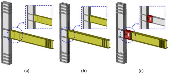
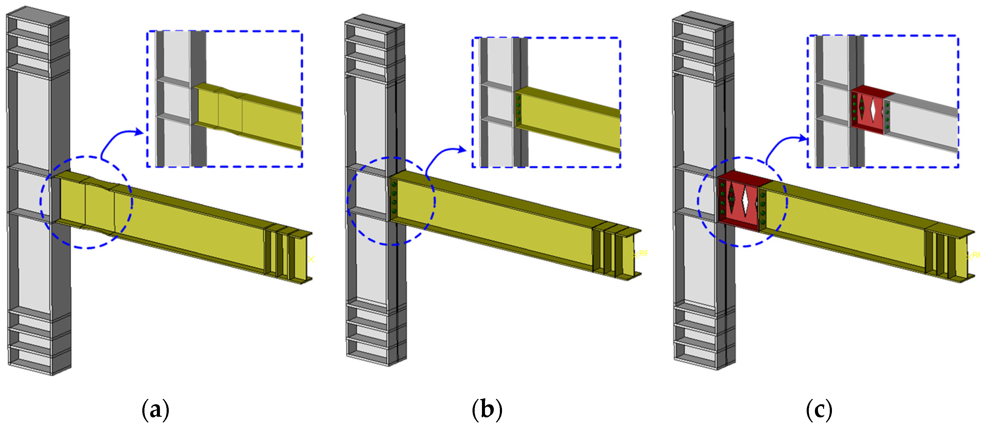
Three steel beam-to-column joint archetypes were considered to represent an evolutionary path from conventional welded detailing to assembled and repair-oriented prefabricated solutions, as shown in Figure 1. The first specimen (W-RBS) adopts a welded moment connection combined with a reduced beam section (RBS) at the beam flanges to promote plastic hinge relocation away from the column face. The second specimen (Bolted) represents a typical assembled joint where the moment transfer is primarily achieved through bolted interfaces. The third specimen (Prefab-web-fuse) further incorporates a replaceable web-reduced segment as a designated “fuse” to intentionally localize inelastic demand within a detachable component, aiming at improved post-event reparability.
Figure 1.
Overview of the three beam-to-column joint archetypes examined in this study: (a) W-RBS welded connection with a reduced beam section at the flanges; (b) Bolted assembled connection with a high-strength bolted interface; (c) Prefab-web-fuse connection incorporating a replaceable web-reduced segment.
2.2. W-RBS: Welded Moment Connection with Reduced Beam Section
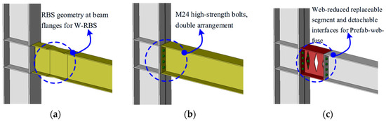
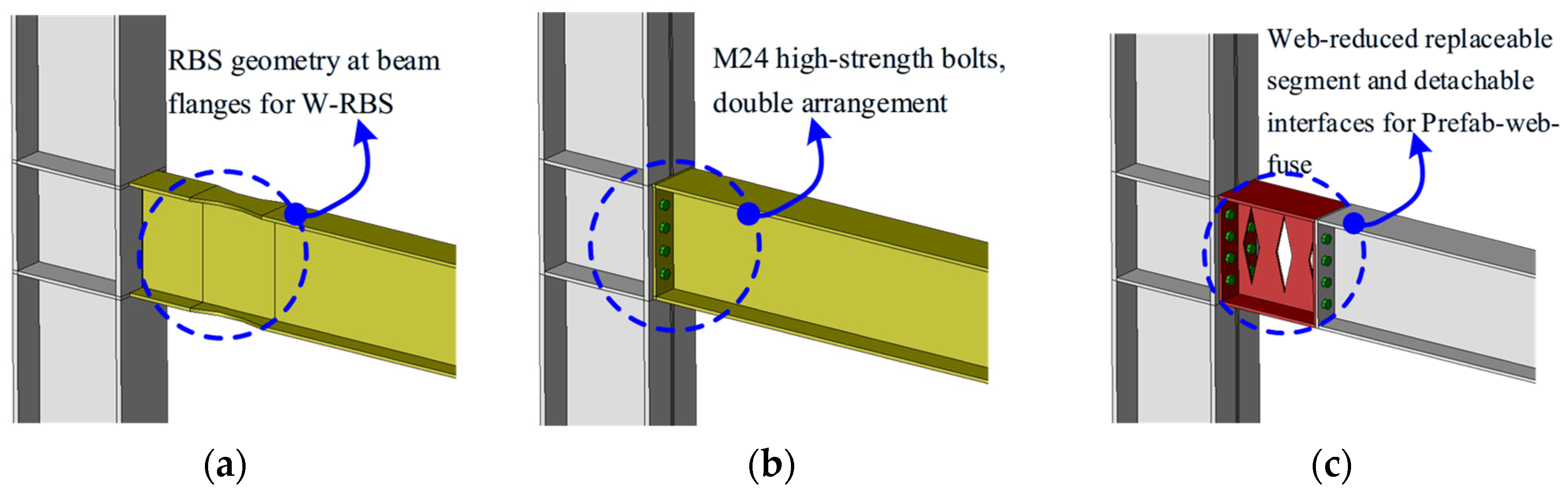
The W-RBS joint adopts a conventional welded moment-resisting detailing, in which the beam is continuously connected to the column face and a reduced beam section (RBS) is introduced at the beam flanges near the joint (Figure 2a). The RBS is implemented by symmetrically trimming the beam flanges with a tapered/curved profile, while keeping the beam web unreduced to maintain a stable shear transfer path. This detailing is intended to relocate the primary plasticity away from the column face, thereby alleviating demand concentration at the welded interface and the column panel zone. The key RBS geometric parameters (e.g., reduction length, reduction depth, and transition radius) are summarized in Table 1.
Figure 2.
Close-up views of the key reduced/fuse regions and connection interfaces: (a) flange-reduced RBS geometry for W-RBS; (b) M24 high-strength bolts in a double-row arrangement for the Bolted joint; (c) replaceable web-reduced fuse segment and detachable interfaces for the Prefab-web-fuse joint.
Table 1.
Summary of joint configurations and key detailing parameters.
2.3. Bolted: Assembled Joint with Bolted Connection Interface
The Bolted joint represents an assembled connection concept, where the beam-to-column moment transfer is achieved through a bolted interface at the beam end region (Figure 2b). High-strength bolts (M24) are arranged in a double-row configuration to provide the tension-compression couple required for bending transfer, while compression is additionally carried through bearing/contact at the faying surfaces. Compared with the welded counterpart, the assembled interface may exhibit distinct stiffness characteristics governed by bolt pretension, contact opening/closure, and localized bearing. The bolt specification, layout (rows/columns), and pretension level adopted in this study are reported in Table 1.
2.4. Prefab-Web-Fuse: Prefabricated Assembled Joint with Replaceable Web-Reduced Segment
The Prefab-web-fuse joint is developed as a repair-oriented prefabricated solution. In this configuration, a web-reduced segment is introduced at the beam end region and connected through detachable interfaces, allowing the reduced segment to be removed and replaced after severe loading. The reduced web segment is intended to act as a sacrificial fuse: it is designed to yield and accumulate plastic deformation earlier than the surrounding primary members and connection components. This strategy aims to (i) confine damage within a replaceable part, (ii) reduce irrecoverable deformation demand on the main beam/column members, and (iii) provide a practical pathway for rapid post-event repair.
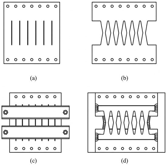
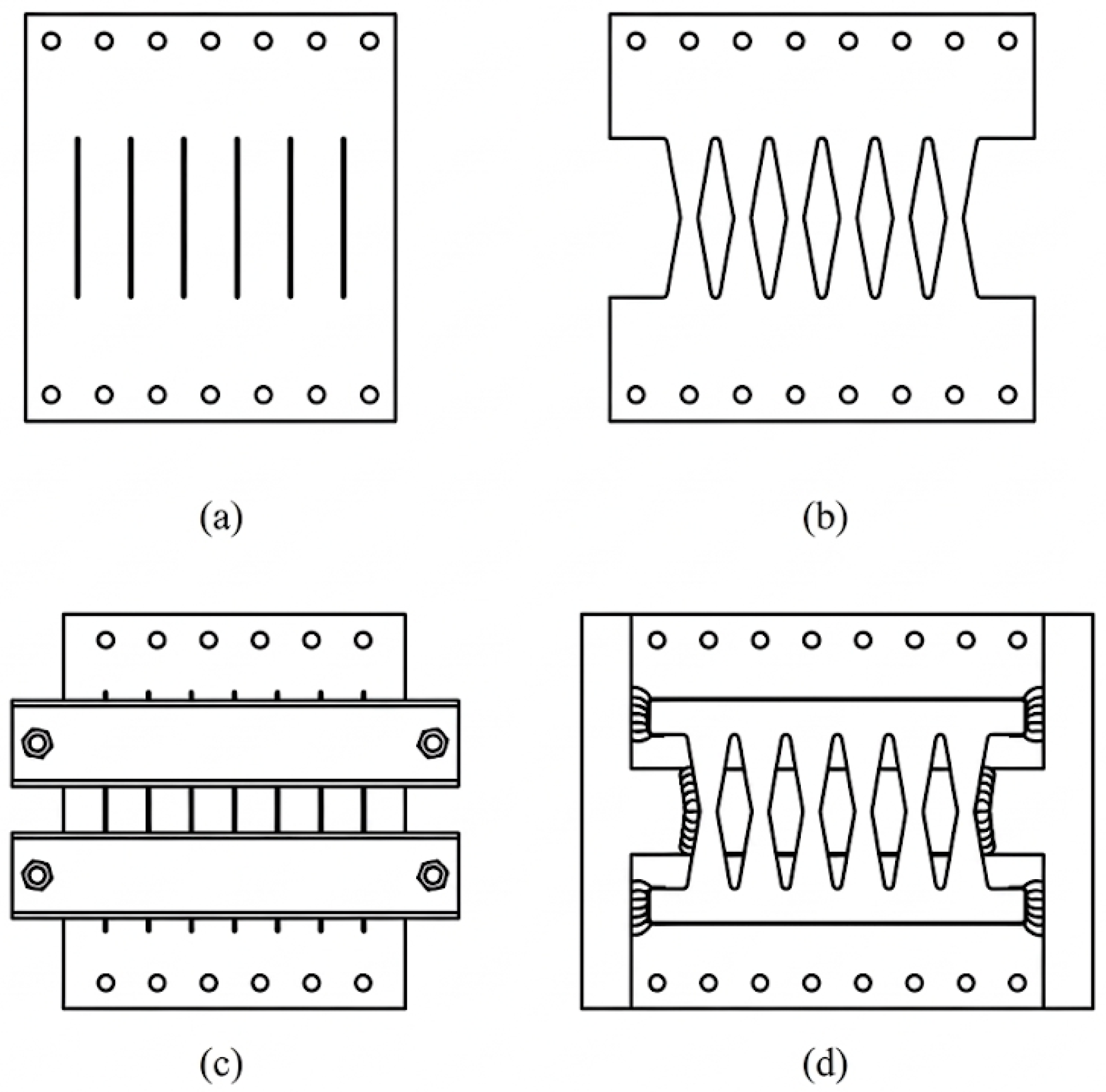
Fuse geometry and detailing rationale. The Prefab-web-fuse archetype is intended to realize a repairability-oriented “protect-and-replace” mechanism by localizing irreversible demand into a detachable sacrificial segment. Because beam-to-column moment connections are flexure-dominated (with flange forces governing the primary bending resistance), the fuse concept avoids intentional weakening of beam flanges and instead promotes a controlled yielding mechanism in the web region. The cutout-based web reduction is inspired by metallic yielding dampers and shear-panel devices, where plasticity is concentrated into a well-defined yielding zone (e.g., slit- or waist-shaped patterns with smooth transitions) to enhance stability and reduce stress concentration [27], as shown in Figure 3. Meanwhile, the surrounding plates/bolt group is detailed with sufficient reserve to avoid premature failure outside the fuse and to minimize unintended load bypass, so that the replaceable web-reduced segment governs the intended inelastic demand. The present fuse configuration is adopted as a representative benchmark; systematic parametric tuning/optimization of the reduction ratio, effective fuse length, and cutout geometry will be pursued in future work, together with experimental calibration.
Figure 3.
Representative slit- and waist-shaped metallic fuse devices for replaceable energy dissipation: (a) slit fuse; (b) butterfly fuse; (c) slit fuse restrained from buckling; (d) butterfly fuse with partial buckling restraining.
To ensure a fair comparison, all three joints share the same beam and column member sizes, material properties, and boundary conditions; the differences are restricted to the connection details and the designated reduced/fuse regions. The key geometric and assembly parameters of the three joints are summarized in Table 1.
2.5. Comparability Statement
To ensure a fair and meaningful comparison, the three joint archetypes share the same beam and column member sections and identical steel material properties. The boundary conditions, reference point (RP) layout, and the definition of the extracted moment-rotation (M-θ) response were kept consistent across all models. For the assembled configurations (Bolted and Prefab-web-fuse), the high-strength bolts were modeled using the same bolt specification and the same pretension level, such that any observed differences in monotonic and cyclic behavior can be attributed primarily to the connection concept and the presence/absence of the reduced/fuse segment, rather than inconsistencies in global member properties or bolt preloading. Moreover, the same contact formulation and friction-related assumptions were applied to the assembled interfaces in Bolted and Prefab-web-fuse to avoid bias arising from differing interface constitutive settings.
Designing all three archetypes to achieve an identical target capacity would require extensive tuning of geometry and detailing parameters (e.g., bolt layout and plate thickness for bolted joints, and reduction ratio/length for fuse segments). While such a design optimization is meaningful, it introduces additional degrees of freedom that may mask the intrinsic mechanism differences among archetypes. The present study therefore focuses on controlled benchmarking and trade-off clarification, and the proposed normalized indices are intended as a screening-level decision tool rather than a direct replacement for connection design procedures.
3. Finite Element Modeling in Abaqus
3.1. Geometry, Elements, and Meshing Strategy
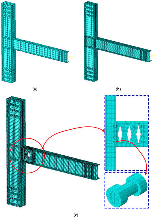
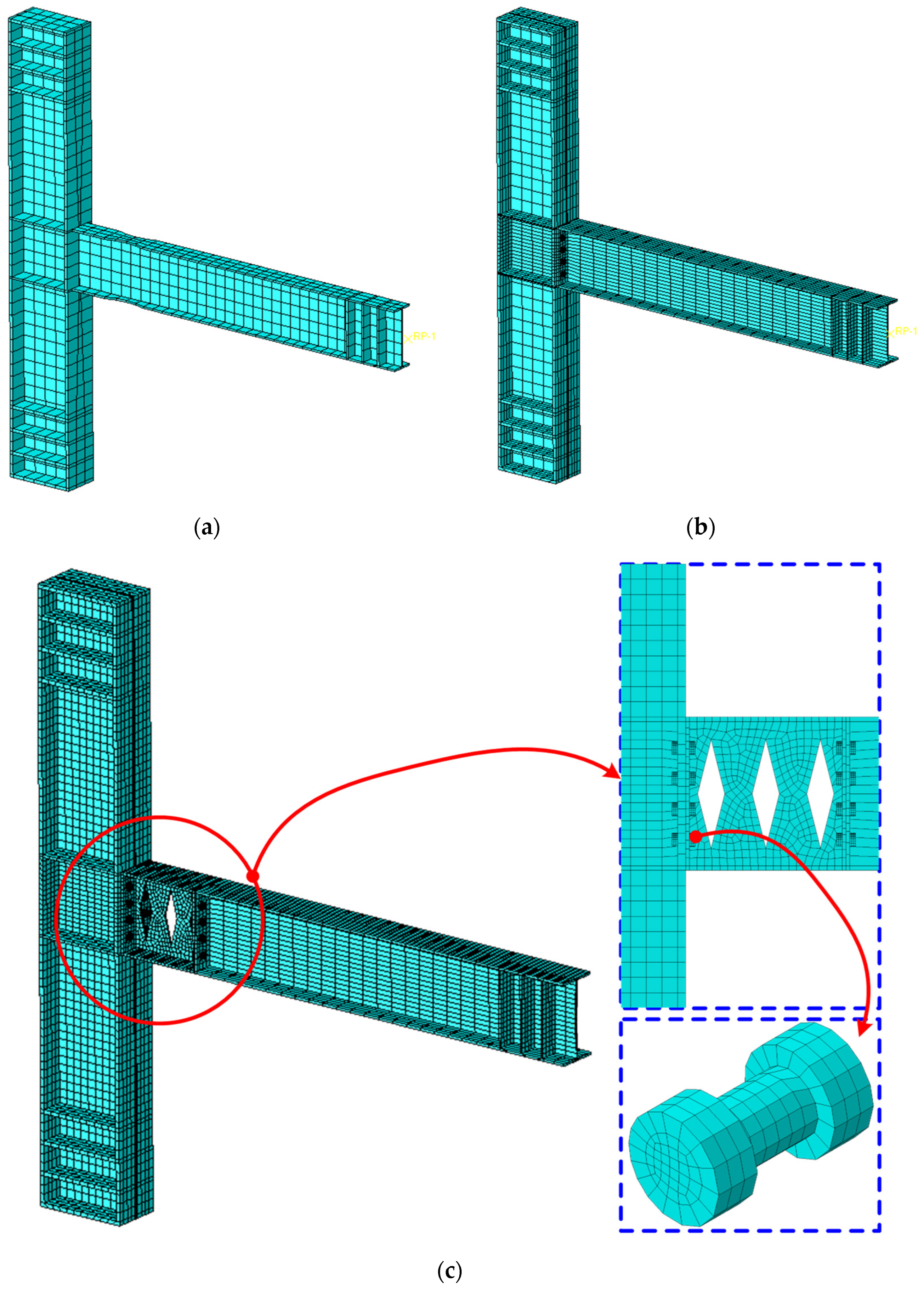
Three beam-to-column joint archetypes (W-RBS, Bolted, and Prefab-web-fuse) were modeled in Abaqus 2020 using identical beam/column member sections and material properties to ensure a consistent comparison (Figure 4). The geometric details of the reduced/fuse regions and connection interfaces follow the joint configurations introduced in Section 2. All models were established as three-dimensional continuum representations to capture local stress transfer and potential concentration effects in the joint core and weakened segments.
Figure 4.
FE model mesh refinement strategy: (a) W-RBS, (b) Bolted, and (c) Prefab-web-fuse.
Eight-node linear brick elements with reduced integration (C3D8R) [28,29,30,31] were employed for steel components, which provide a good balance between computational efficiency and accuracy for nonlinear cyclic simulations. Reduced integration improves robustness in contact-dominated nonlinear analyses and alleviates locking issues that may occur with fully integrated first-order bricks. Potential hourglass behavior was mitigated by using adequate mesh density and controlling element aspect ratios in critical regions (joint core and reduced/fuse zones). A local mesh-refinement check confirmed negligible variation in key response quantities (e.g., initial stiffness and moment at θ = 0.05 rad). A refined mesh was adopted in the joint core, the reduced beam section (RBS) zone for W-RBS, the bolted interface region for Bolted, and the web-reduced replaceable segment for Prefab-web-fuse. Away from these critical regions, a gradually coarsened mesh was used along the beam and column members to reduce computational cost while maintaining stable global stiffness.
To mitigate mesh-induced bias in demand localization, element aspect ratios were controlled, and mesh transitions were kept smooth. A brief mesh-sensitivity check was performed by locally refining the critical zones until the key response quantities (initial stiffness, peak moment at θ = 0.05 rad, and overall M-θ trend) showed negligible variation, indicating that the adopted mesh density is sufficient for the comparative study.
3.2. Material Constitutive Models
All steel components were modeled using an isotropic elastoplastic constitutive model with von Mises yield criterion and isotropic hardening. This hardening rule was adopted because the primary objective of this study is a controlled, mechanism-oriented comparison among connection archetypes under a consistent material framework, focusing on global M-θ trends, stiffness/strength evolution, and dissipation localization rather than detailed cyclic material phenomena. Moreover, the plasticity input is defined by the same true stress-true plastic strain data format for all components, which ensures internal consistency of the comparative assessment. The potential influence of neglecting kinematic hardening (e.g., Bauschinger effect) is acknowledged as a limitation. While kinematic hardening may affect the quantitative loop shape, the adopted approach is adequate for identifying comparative trends and demand localization patterns among the considered joint concepts.
The elastic modulus and Poisson’s ratio were taken as E = 2.0 × 10⁵ MPa and ν = 0.30, respectively. Yield strength and ultimate strength values for the beam/column steels and connection/fuse components are summarized in Table 2. The true stress-true plastic strain relationship was derived from the engineering stress-strain data using standard conversions, and implemented in Abaqus 2020 as a multilinear plasticity curve.
Table 2.
Material properties.
Fracture was not explicitly simulated in the present FE models. The primary objective of this study is to compare the deformation mechanisms and hysteretic characteristics of three joint archetypes within a consistent rotation range; θu = 0.05 rad is adopted as the analysis endpoint because it is sufficient to reveal the distinct response shapes, degradation trends, and dissipation localization required for the intended comparison. Explicit fracture simulation (e.g., element deletion or separation-based approaches) typically requires specimen-specific calibration and may introduce strong mesh dependency and additional uncertainty; without dedicated experimental calibration, it may reduce the robustness and comparability of a controlled benchmarking study. Therefore, the present results are interpreted up to θ = 0.05 rad and should not be used to infer ultimate fracture-controlled capacity beyond the imposed range.
3.3. Contacts, Bolts, and Constraints
All welded interfaces in the W-RBS specimen were idealized as fully rigid by using tie constraints, which emulate full-penetration groove welds and suppress relative slip/opening at the connected surfaces. Therefore, the load transfer is enforced through the connected components without interface compliance, and nonlinearities mainly originate from material yielding and local instability in the reduced beam section (RBS) region.
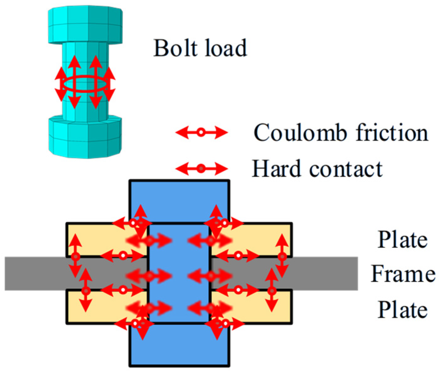
For the bolted-based specimens (Bolted and Prefab-web-fuse), surface-to-surface contact was defined at all intended bearing/sliding interfaces, as shown in Figure 5. In the normal direction, a hard contact formulation was adopted to prevent penetration while allowing separation when contact pressure vanishes. In the tangential direction, a penalty Coulomb friction model was employed with a friction coefficient of μ = 0.45, which lies within the commonly adopted slip/friction coefficient range for steel faying surfaces in slip-critical joints (Class A ≈ 0.30 and Class B ≈ 0.50) and remains below the recommended upper bound (μ ≤ 0.50) [29,32].
Figure 5.
Bolt pretension and contact settings.
High-strength bolts were modeled as M22, grade 10.9, and the bolt tightening effect was introduced using the standard bolt pretension (bolt load/pre-tension section) procedure in Abaqus 2020/Standard: a target pretension force of 190 kN per bolt was applied and subsequently held constant during the loading phase. This pretension level was selected according to the recommended design pretension for M22 (10.9) high-strength bolts in the Chinese steel design standard [33]. The same pretension level was used for both the Bolted and Prefab-web-fuse configurations to ensure a consistent baseline for slip/contact engagement.
For the Prefab-web-fuse connection, detachable bolted interfaces were explicitly retained on both sides of the replaceable web-reduced segment, so that inelastic demand can be intentionally attracted to the fuse region while minimizing unintended load bypass into the main beam/column members.
For clarity, the selected constraint/interaction definitions are directly mapped to the physical interface behavior of the three joint archetypes considered in this study. For the W-RBS specimen, the beam-to-column connection region is idealized as a fully welded continuity detail; hence, no separation or slip is expected across the welded interfaces, and ”tie constraints” are adopted to enforce full kinematic compatibility, representing a rigid welded load path. For the two assembled specimens (Bolted and Prefab-web-fuse), the force transfer is governed by faying/bearing interfaces clamped by high-strength bolts; therefore, relative separation (opening/closure) and tangential slip may occur depending on the contact pressure state and frictional resistance. These interfaces are modeled using ”surface-to-surface contact” with “hard” normal behavior and penalty Coulomb friction in the tangential direction, so that interface opening/closure and slip-related compliance can be captured consistently in the cyclic response.
3.4. Boundary Conditions and Loading Protocols
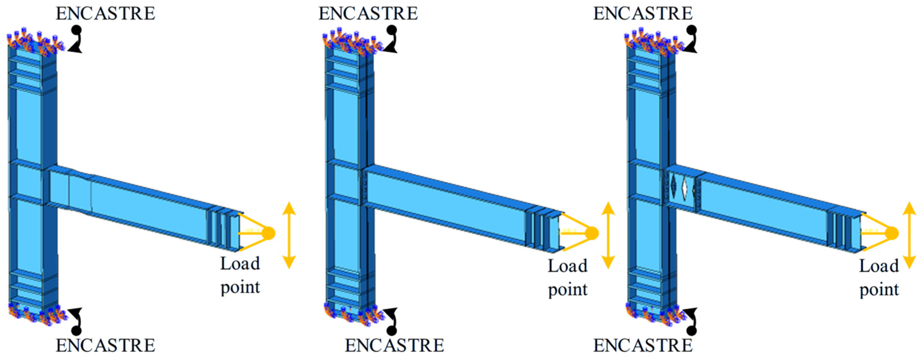
Boundary conditions were defined to reproduce joint deformation under both monotonic and cyclic rotation-controlled protocols using a consistent displacement-controlled scheme (Figure 6). The column base was fully restrained (ENCASTRE). The beam end was controlled through a reference point (RP) kinematically coupled to the beam-end section (coupling/kinematic), so that the RP motion is uniformly transferred to the beam-end loading surface.
Figure 6.
Boundary conditions.
Loading was applied at the same displacement-controlled RP for monotonic and cyclic analyses. The joint rotation was evaluated as θ = Δ/L, where Δ is the prescribed displacement of the loading RP in the loading direction and L = 2000 mm is the lever arm measured along the beam axis from the loading point to the column face. The corresponding joint moment was obtained as M = F·L, where F is the reaction force at the loading RP. Both monotonic and cyclic analyses were conducted using the Static General procedure with geometric nonlinearity enabled (NLGEOM = ON) to capture large-rotation effects and nonlinear contact responses.
Monotonic loading. The joint was subjected to a monotonically increasing target rotation until reaching a prescribed maximum rotation or a termination condition associated with pronounced strength deterioration/numerical instability. The monotonic response is reported in terms of the backbone M-θ curve and the corresponding plastic localization patterns.
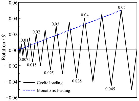
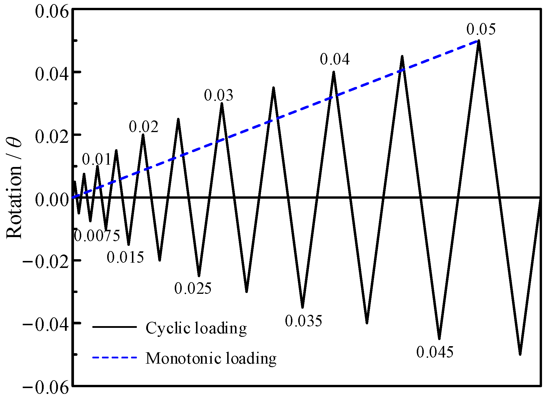
Cyclic loading. A symmetric, stepwise increasing rotation history was applied, as illustrated in Figure 7. The protocol consists of fully reversed rotation cycles with peak rotations sequentially increased to ±0.005, ±0.0075, ±0.01, ±0.015, ±0.02, ±0.025, ±0.03, ±0.035, ±0.04, ±0.045, ±0.05 rad forming a gradually amplified triangular waveform in the time domain. This protocol enables a consistent assessment of hysteretic characteristics, degradation behavior, energy dissipation, and residual rotation across different connection concepts.
Figure 7.
Rotation-controlled loading protocols used in the analyses: monotonic loading (dashed line) and fully reversed cyclic loading (solid line) with stepwise increased peak rotations up to ±0.05 rad.
3.5. Definition and Extraction of M-θ
The moment-rotation response was extracted from the FE outputs using a consistent definition for all connection types.
The connection rotation (θ) was defined as the relative rotation between the beam end section adjacent to the column face and the column reference section, about the strong axis of bending. In the FE model, two section-based reference points (RPs) were created at the centroids of the corresponding beam and column reference sections. Each RP was coupled to the nodes on the section through distributing coupling constraints, so that the RP rotational degree of freedom represents the mean (section-averaged) rotation of the section about the bending axis while reducing the influence of local deformation/noise. The connection rotation was then calculated as the difference between the beam-section RP rotation and the column-section RP rotation, i.e.,
where θbeam and θcolumn are the strong-axis rotations of the coupled beam and column reference sections, respectively. This definition reduces contamination from flexural deformation of the beam span outside the joint core and provides a direct measure of joint rotational demand.
The connection moment (M) was taken as the reaction moment about the strong axis at the beam-end coupled RP located at the column face. The sign convention was selected such that positive M corresponds to positive θ in the imposed loading direction. For cyclic analyses, M-θ hysteresis loops were constructed directly from the synchronized time histories of θ and the reaction moment.
Output implementation. In Abaqus, the required quantities were obtained from the history outputs at the relevant RPs, including rotational DOFs for θ and reaction moments (RM components) for M. The same RP placement and output definitions were used for all three joint archetypes to ensure comparability.
3.6. Model Verification
In principle, finite-element model validation is best established by reproducing independent experimental results and demonstrating agreement in global responses (e.g., initial stiffness, peak strength, post-yield trends) and local mechanisms (e.g., yielding/buckling locations and damage patterns). In the present study, the primary objective is a controlled comparison among three joint archetypes under an internally consistent modeling framework. To strengthen numerical credibility and directly address the reviewer concerns, a published cyclic test reported by Guo and Wang [19] is adopted as an external benchmark. The selected benchmark is particularly relevant because it features fuse-enabled connection behavior and exhibits cyclic characteristics (pinching, degradation, and energy dissipation) governed by connection detailing.
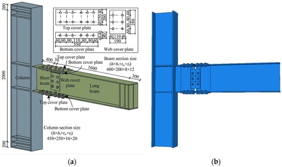
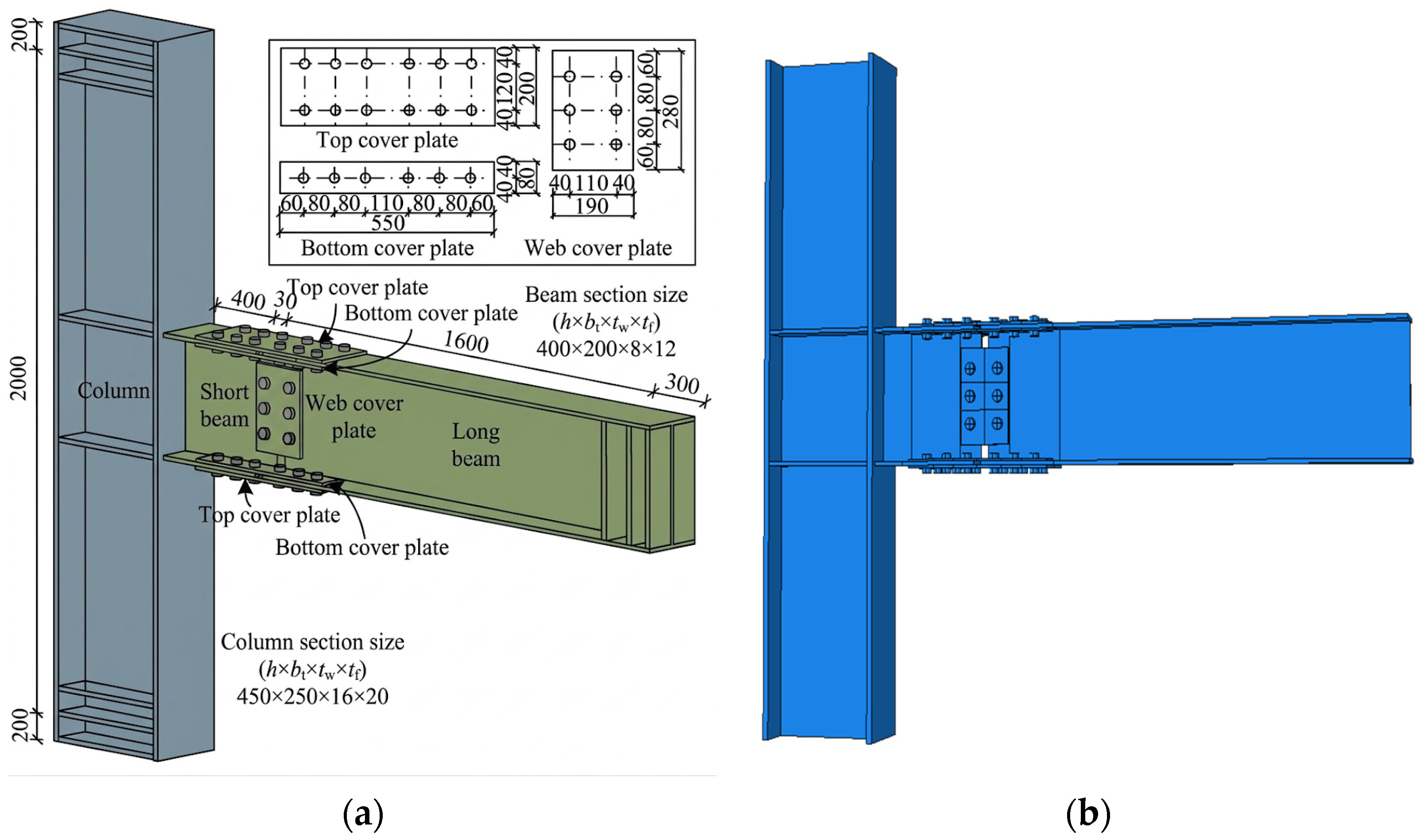
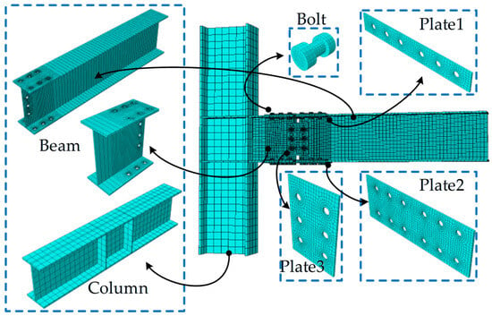
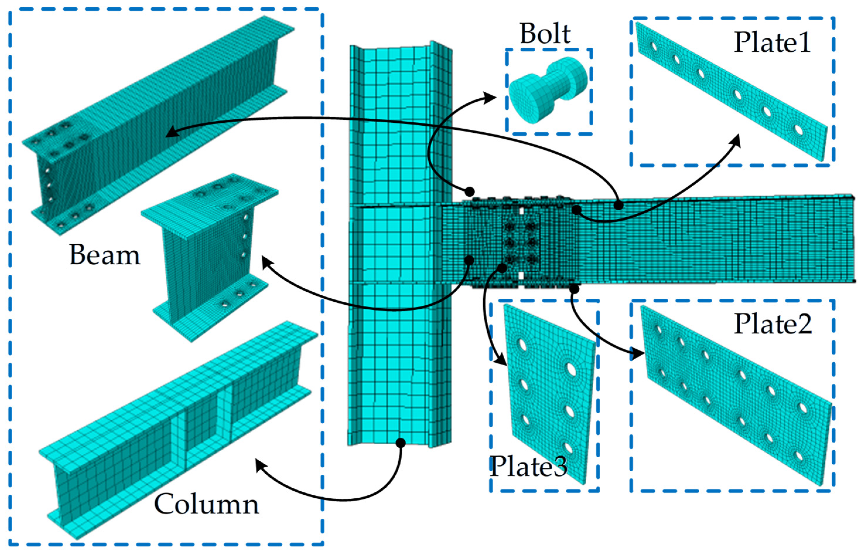
Figure 8a presents the experimental connection configuration and key detailing adopted from [19], and Figure 8b shows the corresponding Abaqus FE model established in this study. The model follows the same core modeling philosophy as the main manuscript, including consistent material plasticity input, contact formulation, and bolt pretension implementation. The meshing strategy is summarized in Figure 9. Because the stress state and contact interactions are most complex around bolts and faying/bearing interfaces, local mesh refinement is enforced in these regions (bolt holes, bearing/sliding surfaces, and the connection core/fuse zone), while a structured/hexa-dominant mesh with smooth transitions is used in prismatic regions to maintain computational efficiency and numerical robustness without sacrificing accuracy.
Figure 8.
Validation benchmark and corresponding FE model. (a) Connection configuration and key detailing of the experimentally tested specimen with low-yield-point steel fuse components, adapted from [19]; (b) corresponding Abaqus finite-element model developed in this study for validation, with consistent assembly details and loading reference definition.
Figure 9.
Meshing strategy of the validation FE model. Structured/hexa-dominant meshing is adopted for prismatic regions to ensure computational efficiency and numerical robustness, while local mesh refinement is enforced in stress-gradient- and contact-sensitive regions (e.g., around bolt holes, bearing/sliding interfaces, and the fuse/connection core) to capture complex stress transfer and local inelasticity.
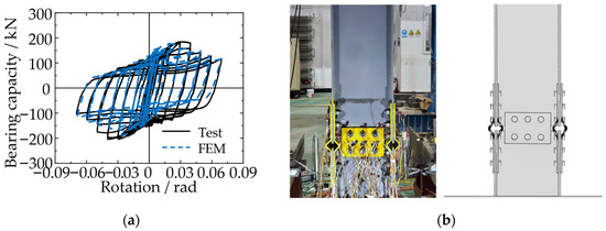
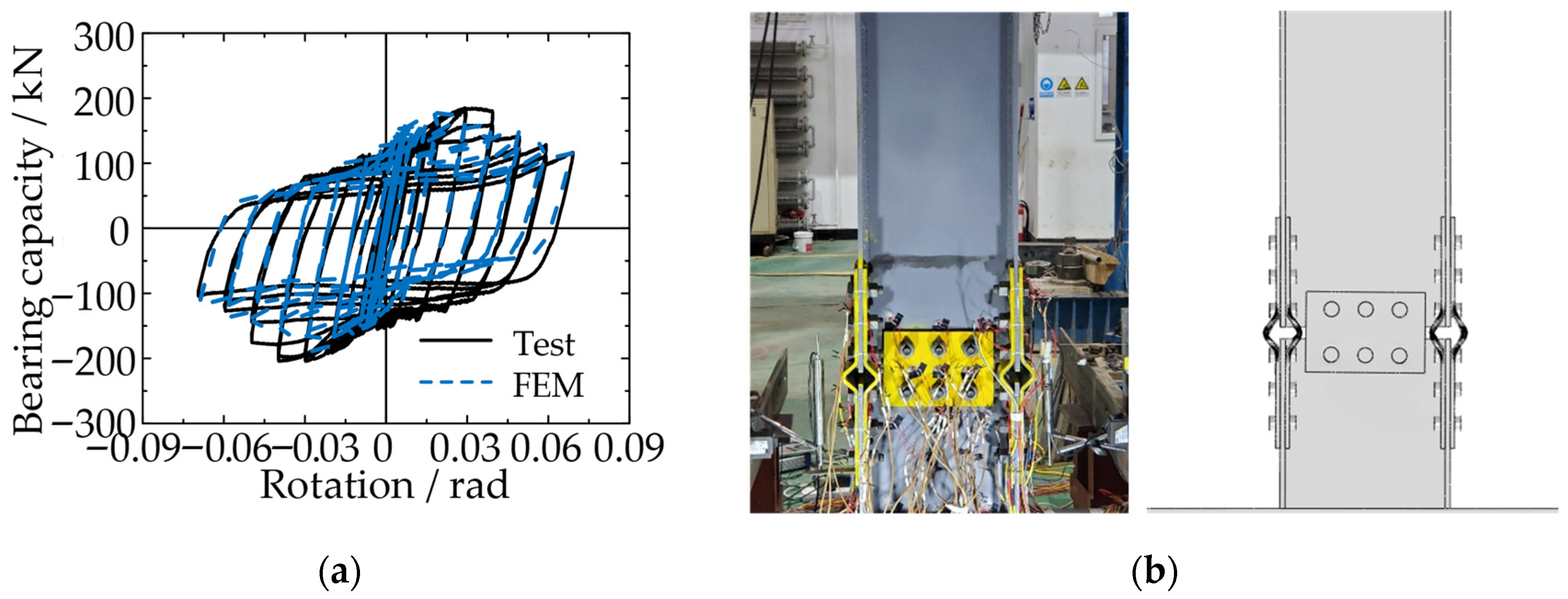
Validation comparisons are provided in Figure 10. The FE simulation reproduces the global cyclic response trends observed in the test, including the overall loop shape and pinching tendency (Figure 10a). In addition, the predicted localization pattern in the connection region is consistent with the experimentally observed damage/failure characteristics (Figure 10b), supporting mechanism-level agreement. Overall, the benchmark validation demonstrates that the adopted FE modeling approach is sufficiently accurate to capture the key cyclic behavior features relevant to this study (pinching/slip-related compliance, degradation trends, and damage localization), thereby providing confidence in applying the same modeling framework to the comparative assessment of the three joint archetypes presented in this paper.
Figure 10.
Validation results against the published cyclic test. (a) Comparison of the cyclic response between experiment and FE simulation (test vs. FEM), showing the overall loop shape and pinching trend; (b) representative experimental damage/failure observation at the connection region.
The above validation provides quantitative and mechanism-level evidence that the proposed FE approach can reliably reproduce the cyclic response characteristics of fuse-enabled steel moment connections, supporting its use for the comparative investigations in this manuscript.
4. Monotonic Moment-Rotation Response
It should be noted that the three connections are investigated as representative archetypes rather than being tuned to meet a common strength or stiffness target. To isolate the influence of connection concept, all models share identical beam/column member sections and steel material properties, and the same boundary conditions, loading protocol, and M-θ extraction definitions are used. For the assembled joints (Bolted and Prefab-web-fuse), the friction/contact formulation and bolt pretension level are also kept identical, establishing a consistent baseline for interface engagement. Under these controlled settings, differences in absolute capacity are expected because the force-transfer mechanisms differ by concept; therefore, both absolute M-θ responses and normalized indices are reported to support a fair mechanism-oriented comparison.
Accordingly, the normalized indices reported herein are evaluated under the prescribed loading protocol and the adopted interface assumptions, and they should be interpreted as benchmarking measures within the unified setting of this study rather than universal constants independent of interface conditions, target rotation level, or fuse geometry.
4.1. Backbone Curves and Key Points
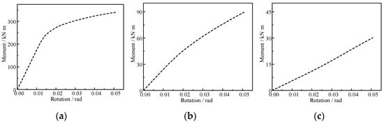
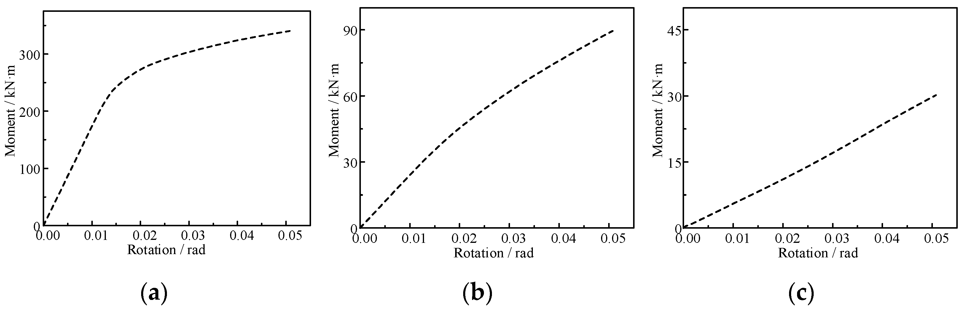
Figure 11 compares the monotonic moment-rotation responses of the three joint archetypes. The results indicate a pronounced difference in absolute moment resistance among the compared concepts. W-RBS develops the highest moment capacity and exhibits a clear transition from an initial near-linear stage to a post-yield regime with gradually reduced tangent stiffness. In contrast, Bolted and Prefab-web-fuse demonstrate substantially lower moment levels over the investigated rotation range, reflecting their assembled and fuse-oriented force transfer mechanisms. At the maximum rotation of 0.05 rad, the peak moment of W-RBS is on the order of several hundred kN·m, whereas Bolted and Prefab-web-fuse remain at markedly lower levels.
Figure 11.
Monotonic moment-rotation (M-θ) responses of the three joint archetypes: (a) W-RBS; (b) Bolted; (c) Prefab-web-fuse.
To enable a behavior-oriented comparison that is not dominated by strength level, normalized indicators are introduced in the subsequent cyclic assessment. In particular, the cyclic hysteretic characteristics are presented in terms of M/Mu versus θ, which highlights loop shape, pinching, and degradation trends irrespective of absolute capacity.
The monotonic moment-rotation (M-θ) response of each joint was obtained from the FE analysis by converting the extracted actuator force P to the column-face bending moment M through
where L = 2.0 m is the distance from the loading point to the column face.
The ultimate rotation was taken as the maximum imposed rotation, θu = 0.05 rad, and the corresponding moment was defined as Mmax = M(θu).
To ensure a consistent comparison among the three joint archetypes with markedly different strength levels, a constrained bilinear idealization was adopted to identify the yield point (θy, My). The bilinear curve was forced to pass through the origin and the ultimate point (θu, Mu), while the yield rotation θy was determined by minimizing the least-squares error between the FE curve and the bilinear approximation. The initial and post-yield stiffnesses were then calculated as
The rotational ductility was evaluated as
Table 3.
Monotonic backbone parameters of the three joint archetypes.
4.2. Stiffness Characteristics
The monotonic moment-rotation (M-θ) responses reveal distinct stiffness characteristics among the three joint archetypes, which can be interpreted in terms of their primary load-transfer mechanisms and interface compliance. The initial stiffness K0 is evaluated as the secant stiffness at the smallest effective rotation level in the loading history (θ = 0.005 rad), using K0 = M/θ. Under this definition, the three joints exhibit comparable initial stiffness levels, indicating that the global elastic stiffness is mainly governed by the beam-column member properties that are kept identical across the models.
With increasing rotation, the post-yield stiffness and stiffness retention diverge significantly. The W-RBS joint shows a rapid reduction in secant stiffness after yielding, consistent with the intended formation and development of a flexure-dominated plastic hinge in the reduced beam section. In contrast, the Bolted and Prefab-web-fuse joints exhibit a milder stiffness degradation trend; their response is influenced by interface-related compliance, such as contact separation/closure and local deformations around assembled regions, which can reduce effective stiffness in the early nonlinear stage without requiring extensive yielding in the primary members.
Notably, the Prefab-web-fuse joint maintains an almost constant secant stiffness over the investigated rotation range. This behavior indicates that the main beam-column members remain largely elastic and that the deformation is accommodated by the designed fuse mechanism and local interface effects. Such stiffness stability is favorable for controlling drift accumulation; however, it may also imply delayed activation of inelastic dissipation, which is discussed in the subsequent sections together with the stress-field evidence.
4.3. Plastic Localization and Mechanism
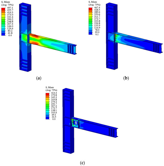
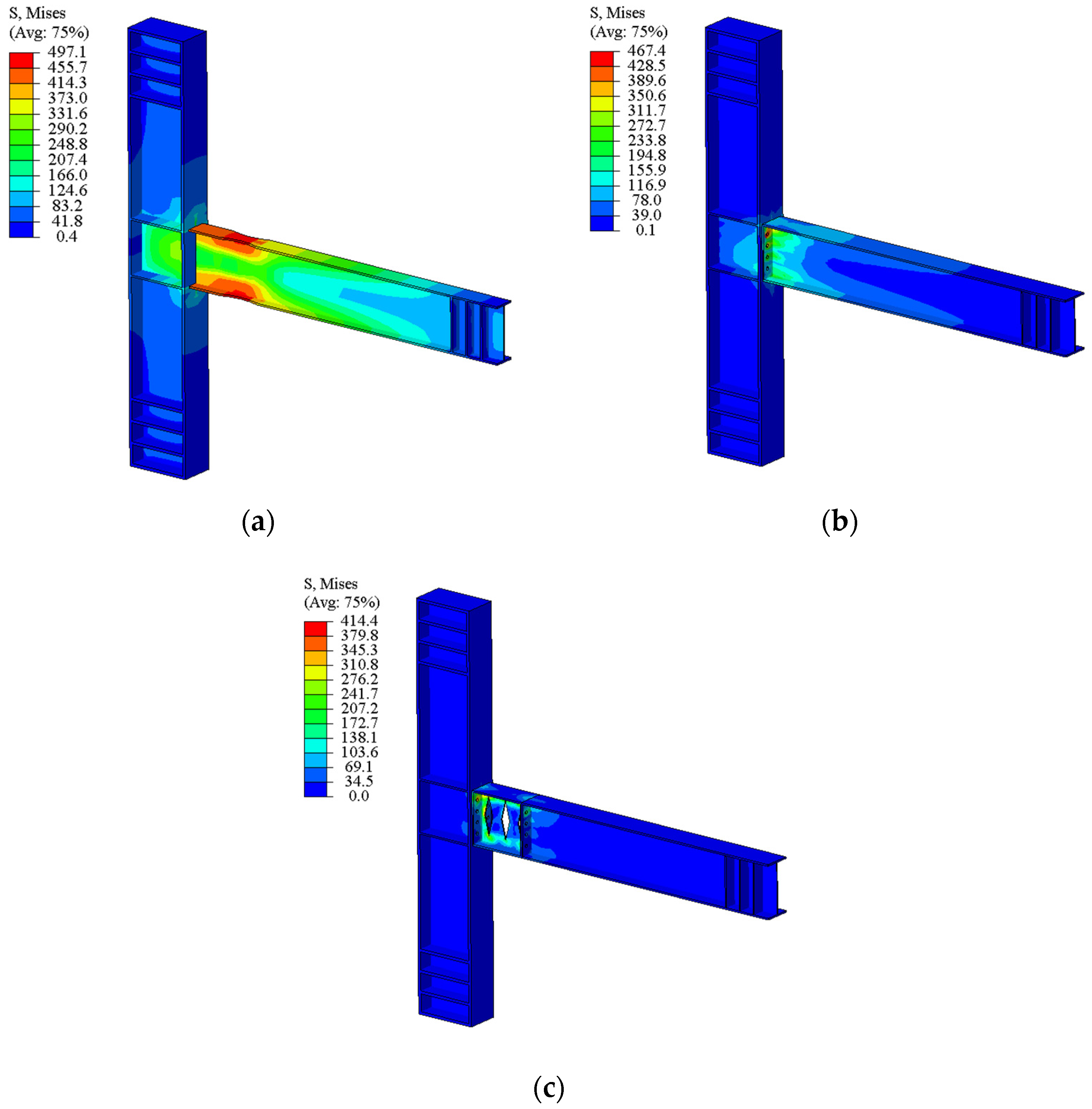
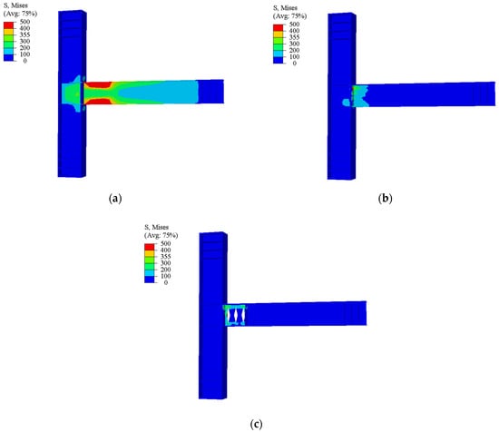
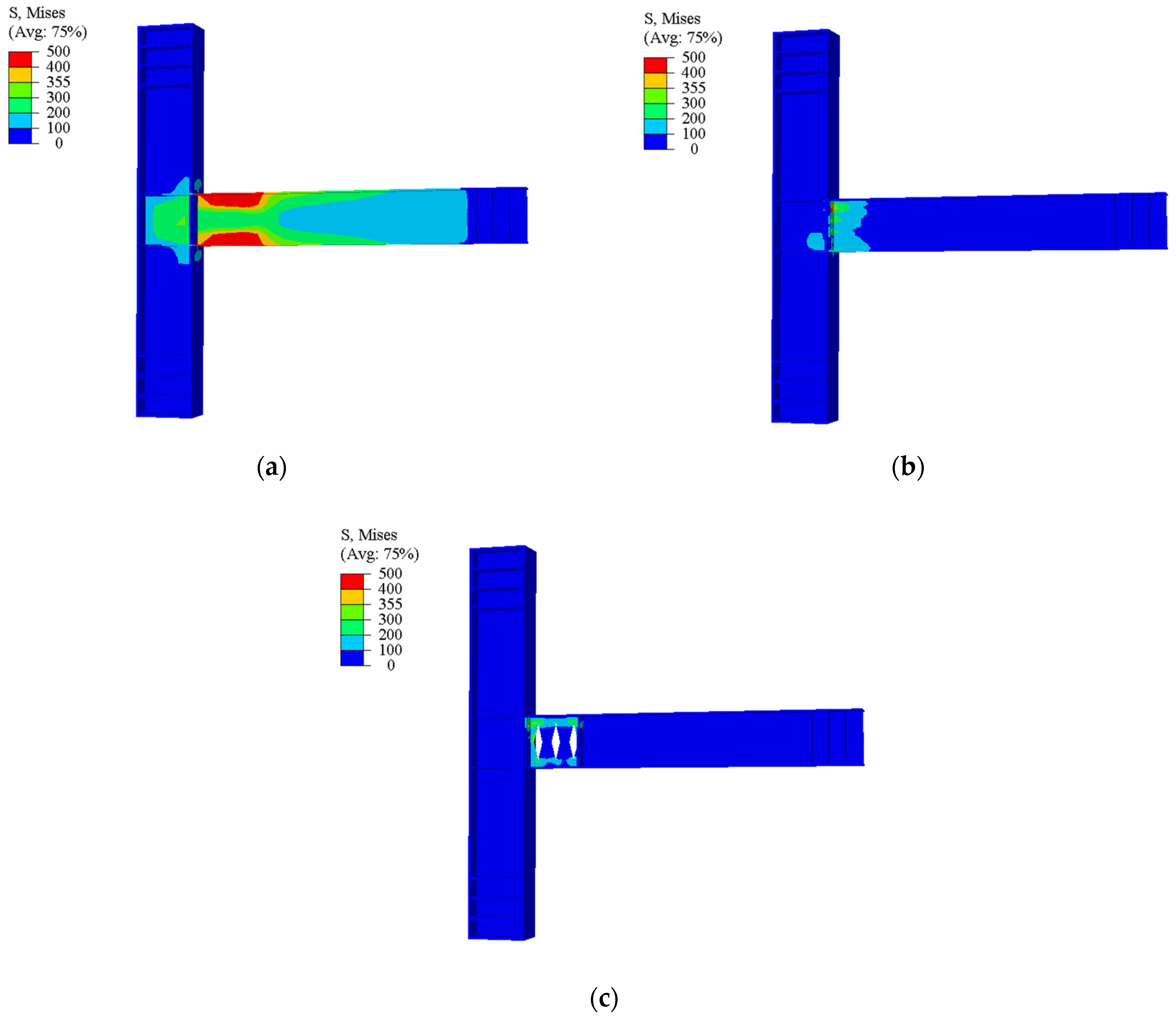
Representative von Mises stress contours at the same rotation level (θ = 0.05 rad) are compared for the three joint archetypes to reveal their distinct stress-transfer paths and demand localization characteristics (Figure 12). Using an identical deformation state enables a direct identification of the critical regions that govern strength mobilization and the subsequent cyclic response.
Figure 12.
Representative von Mises stress contours at θ = 0.05 rad: (a) W-RBS, (b) Bolted, and (c) Prefab-web-fuse.
For the W-RBS joint (Figure 12a), high stresses concentrate around the reduced beam section near the beam end and extend into adjacent beam segments, indicating a flexure-dominated mechanism with a distributed high-demand region along the beam. This observation is consistent with the intended formation of a plastic hinge away from the column face and provides a mechanistic explanation for its rapid strength mobilization and pronounced stiffness degradation.
For the Bolted joint (Figure 12b), the stress field is more localized in the assembled connection region near the beam-column interface, while the beam away from the interface remains at a relatively low demand level. This suggests that the load transfer is governed by the bolted interface and bolt-group actions, which introduces local compliance and is consistent with the pinched hysteretic response observed under cyclic loading.
For the Prefab-web-fuse joint (Figure 12c), the peak stresses are intentionally concentrated within the designated web-reduced replaceable segment, whereas the main beam and column members sustain comparatively low stress levels at the same global rotation. This localization pattern supports the targeted “damage-in-fuse” mechanism, providing monotonic evidence that the inelastic demand can be steered into a replaceable component to protect primary members. The above monotonic stress-localization characteristics motivate the cyclic evaluations in Section 5, where degradation trends and dissipation localization are quantified through M-θ loops and ALLPD-based energy partition.
These monotonic stress-localization patterns motivate the cyclic evaluations in Section 5, where pinching, stiffness/strength degradation, and dissipation localization are quantified.
5. Cyclic Response Under Increasing Rotation Amplitudes
5.1. Hysteresis Loops and Pinching/Slip Characteristics
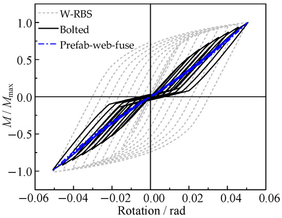
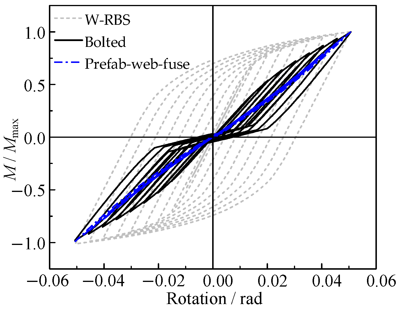
Figure 13 presents the normalized hysteresis loops of the three joints in terms of M/Mmax versus rotation θ. After normalization, distinct hysteretic signatures can be clearly identified. W-RBS exhibits comparatively fuller hysteresis loops with limited pinching, indicating stable inelastic response consistent with the intended plastic mechanism associated with the reduced beam section. By contrast, Bolted shows noticeable pinching and a more pronounced reduction in loop area near the origin, which can be attributed to interface-related effects (e.g., contact opening/closure and localized bearing/slip) typical of assembled connections. Prefab-web-fuse displays a comparatively narrower hysteretic response with a near-linear trend at small-to-moderate rotation levels, suggesting a different inelastic participation pattern governed by the web-reduced fuse concept.
Figure 13.
Normalized cyclic hysteresis loops of the three joints under the prescribed rotation protocol, presented as M/Mmax versus rotation θ (θ in rad). All plotted quantities are normalized and dimensionless.
Overall, the normalized loops demonstrate that, although the three joints operate at different absolute strength levels, their cyclic performance differs substantially in terms of hysteretic fullness and pinching severity, motivating a further quantitative comparison in terms of strength/stiffness degradation, energy dissipation, and residual rotation.
5.2. Quantitative Comparison of Cyclic Strength and Stiffness
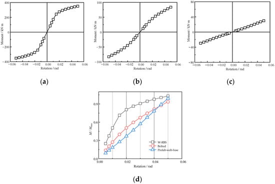
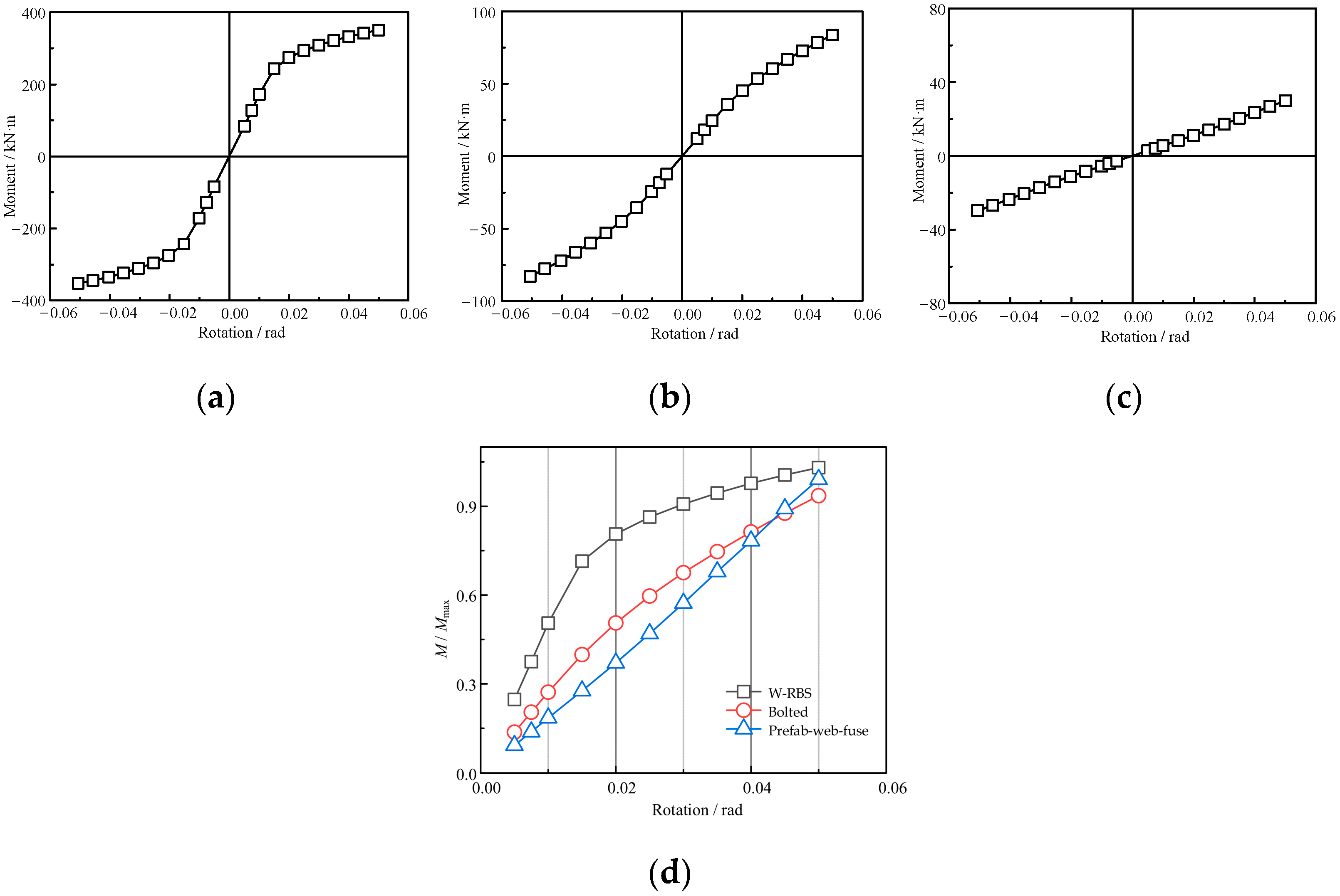
To quantify cyclic degradation in a consistent manner across joints with markedly different strength scales, the peak moment from monotonic loading at θ = 0.05 rad is adopted as the reference maximum moment: Mmax,W-RBS = 340.15 kN·m, Mmax,Bolted = 89.52 kN·m, Mmax,Prefab-web-fuse = 30.15 kN·m for W-RBS, Bolted, and Prefab-web-fuse, respectively. In terms of absolute capacity, Bolted and Prefab-web-fuse reach approximately 26.3% and 8.9% of W-RBS, highlighting the distinct design positioning of the assembled and fuse-based concepts.
5.2.1. Peak Moment Evolution with Rotation Amplitude
For each imposed rotation amplitude θi, the positive and negative peak moments are extracted as and from the hysteresis loop. When multiple repeated cycles are applied at the same θi, the first-cycle peaks are denoted and subsequent-cycle peaks , etc., to examine within-amplitude strength deterioration.
A normalized peak moment measure is defined as:
where Mmax is specimen-specific. This normalization allows peak-strength trends to be compared without being dominated by absolute strength level.
A strength retention ratio is introduced to describe the loss of peak moment capacity with increasing deformation demand:
where Mp,i may be taken as the average of the two directions, . The reference Mp,ref can be chosen as the peak moment at the first nontrivial amplitude (e.g., θ = 0.0075) or the peak moment at the first cycle of each amplitude if repeated cycles are used. The chosen reference should be stated explicitly and applied uniformly to all specimens.
At θ = 0.02 rad, the W-RBS already mobilizes about 80.6% of its monotonic reference capacity ( = 0.806), whereas the Bolted and Prefab-web-fuse reach 50.6% and 37.1%, respectively. With increasing rotation demand, all joints show increasing peak moments; at θ = 0.04 rad, rises to 0.977 (W-RBS), 0.813 (Bolted), and 0.783 (Prefab-web-fuse). At θ =0.05 rad, the averaged cyclic peaks are 350.60 kN·m (W-RBS), 83.75 kN·m (Bolted), and 29.88 kN·m (Prefab-web-fuse). The slightly higher value above unity for W-RBS reflects mild cyclic hardening relative to the monotonic reference at the same target rotation, as shown in Figure 14.
Figure 14.
Strength mobilization with increasing rotation amplitude: peak points extracted from cyclic loops for (a) W-RBS, (b) Bolted, and (c) Prefab-web-fuse; (d) normalized averaged peak moment = Mp,avg/Mmax versus rotation amplitude.
5.2.2. Secant Stiffness and Stiffness Degradation
To evaluate stiffness deterioration, a secant stiffness at each amplitude is defined using the peak response:
and the normalized stiffness degradation ratio is computed as:
with θref taken as the smallest stable amplitude in the protocol.
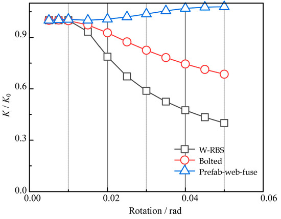
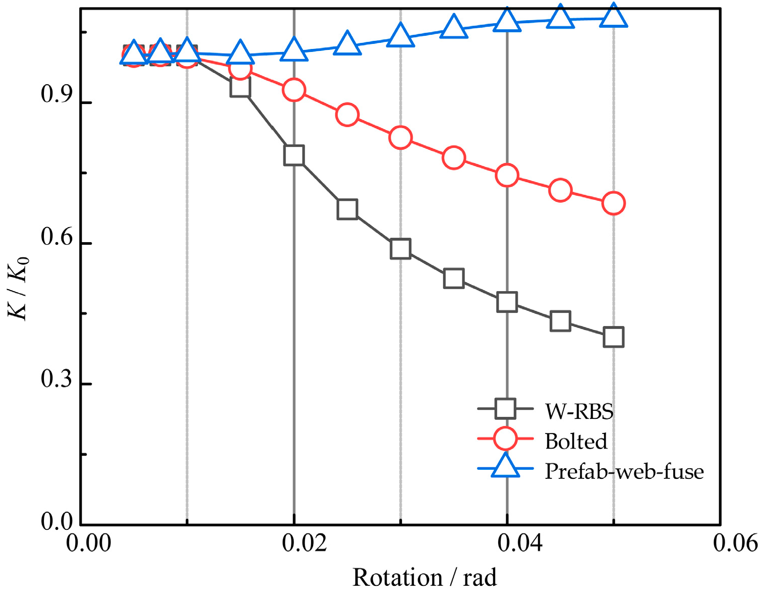
In terms of stiffness, W-RBS exhibits the most pronounced degradation: Ksec drops to 6943 kN·m/rad at θ = 0.05 rad, corresponding to Ksec/K0 = 0.400. The Bolted joint shows a moderate reduction to 1650 kN·m/rad (Ksec/K0 = 0.686). In contrast, the Prefab-web-fuse maintains an almost constant secant stiffness (Ksec/K0 ≈ 1.08 at θ = 0.05 rad), consistent with its nearly linear, low-damage cyclic response within the investigated rotation range (Figure 15). Detailed peak-moment and stiffness metrics across all rotation levels are summarized in Table 4.
Figure 15.
Normalized secant stiffness degradation Ksec/K0 as a function of rotation amplitude for the three joints, where Ksec = Mp,avg/θ and K0 is the reference secant stiffness at the smallest effective amplitude.
Table 4.
Cycle-by-cycle strength and secant stiffness indices at each target rotation amplitude.
5.3. Energy Dissipation and Equivalent Damping
The energy dissipated in each cycle at amplitude θi is computed as the enclosed area of the corresponding hysteresis loop:
The cumulative hysteretic energy up to a target rotation level is:
Because absolute energy scales with strength, a normalized cumulative energy index is recommended for cross-comparison:
This definition uses the same reference moment Mmax adopted for loop normalization and provides a compact, dimensionless measure of “energy capacity” relative to the specimen’s strength level.
To provide a widely used engineering indicator for cyclic energy dissipation, an equivalent viscous damping ratio can be evaluated at each amplitude:
where Es,i is the recoverable strain energy associated with the secant stiffness at θi. A practical definition for symmetric loops is:
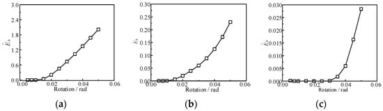
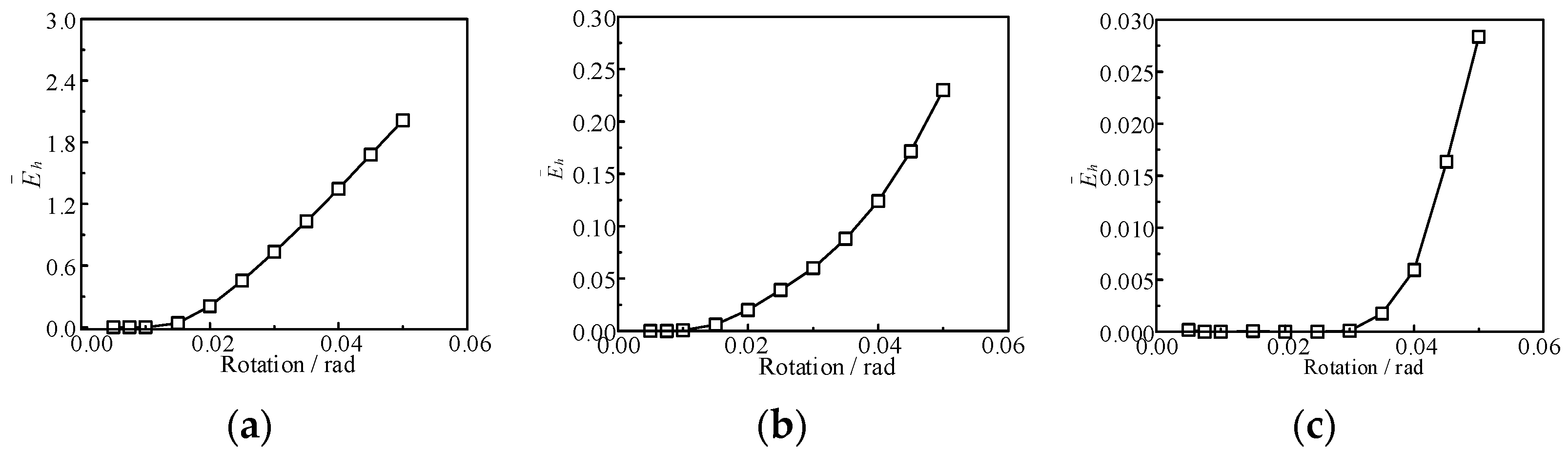
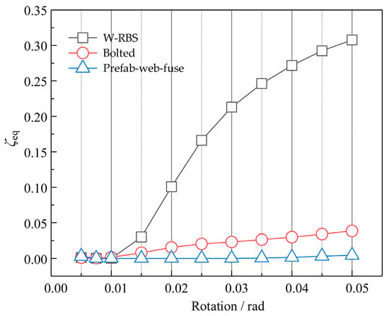
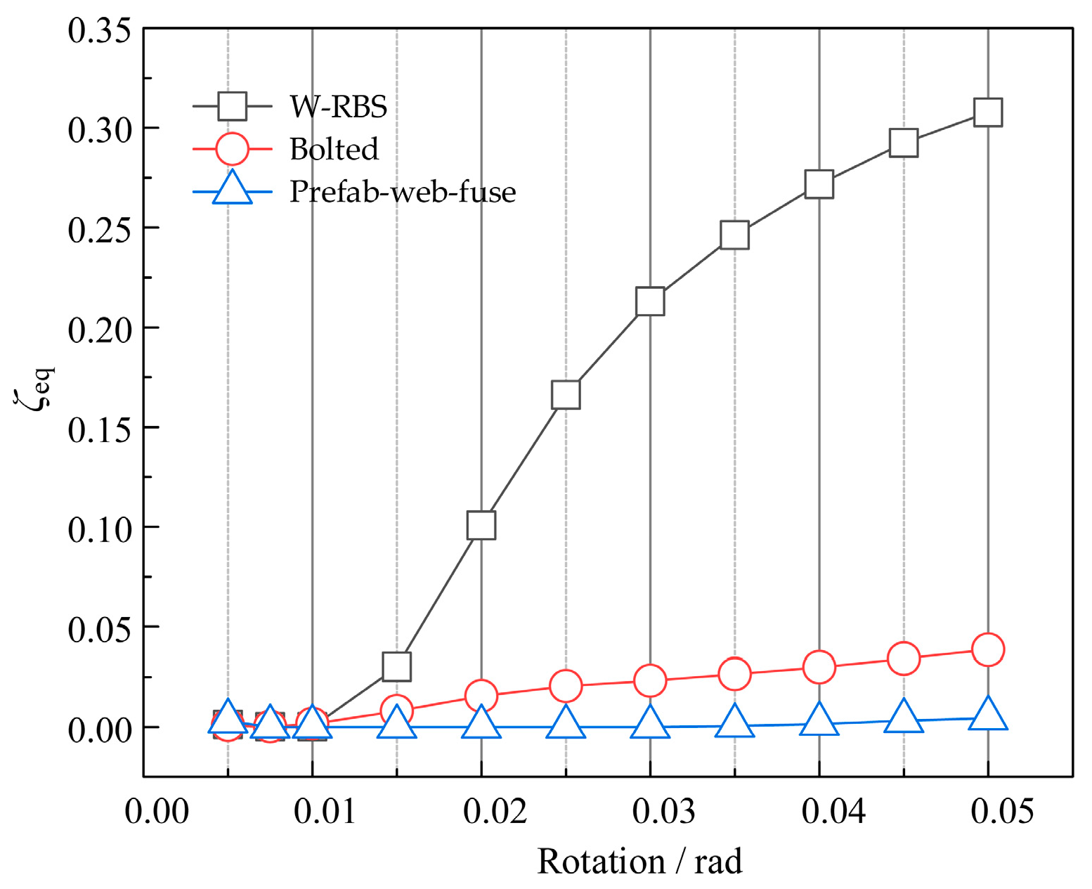
At θ = 0.05 rad, W-RBS shows a substantially larger loop area (Eh = 34.23 kN·m·rad) than Bolted (Eh = 1.03 kN·m·rad) and Prefab-web-fuse (Eh = 0.043 kN·m·rad), as shown in Figure 16. The corresponding normalized indices are 2.013, 0.230, and 0.028, respectively, highlighting the order-of-magnitude differences in hysteretic energy dissipation. This contrast is also reflected by ξeq at θ = 0.05 rad: 0.308 (W-RBS), 0.0386 (Bolted), and 0.00450 (Prefab-web-fuse), indicating a full and stable loop for W-RBS, a markedly pinched response for the Bolted joint, and an almost elastic response for the Prefab-web-fuse within the present loading protocol, as shown in Figure 17.
Figure 16.
Normalized cumulative energy = Eh,cum/(Mmaxθu) versus rotation amplitude: (a) W-RBS, (b) Bolted, and (c) Prefab-web-fuse.
Figure 17.
Equivalent viscous damping ratio ξeq versus rotation amplitude for the three joint archetypes.
Over the entire cyclic history up to θ = 0.05 rad, the cumulative dissipated energies are 127.57, 3.31, and 0.079 kN·m·rad for W-RBS, Bolted, and Prefab-web-fuse, respectively (normalized cumulative indices: 7.50, 0.740, and 0.053). These results quantitatively confirm that the three joints trade energy dissipation capacity for constructability and replaceability in distinct ways. Full-cycle energy and damping metrics at each rotation level are provided in Table 5.
Table 5.
Energy dissipation and equivalent viscous damping at each target rotation amplitude.
5.4. Damage Localization and Reparability Assessment Based on Component-Wise Plastic Dissipation (ALLPD)
To quantitatively evaluate damage concentration and the protection of primary members, component-wise plastic dissipation energies were extracted from Abaqus output ALLPD and integrated within predefined component sets. For the Prefab-web-fuse joint, the beam was further decomposed into a replaceable fuse segment (Beam1) and the remaining non-fuse portion (Beam2), whereas for W-RBS and Bolted joints the fuse-related term was taken as zero. The total plastic dissipation is , and two ratios are introduced:
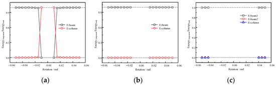
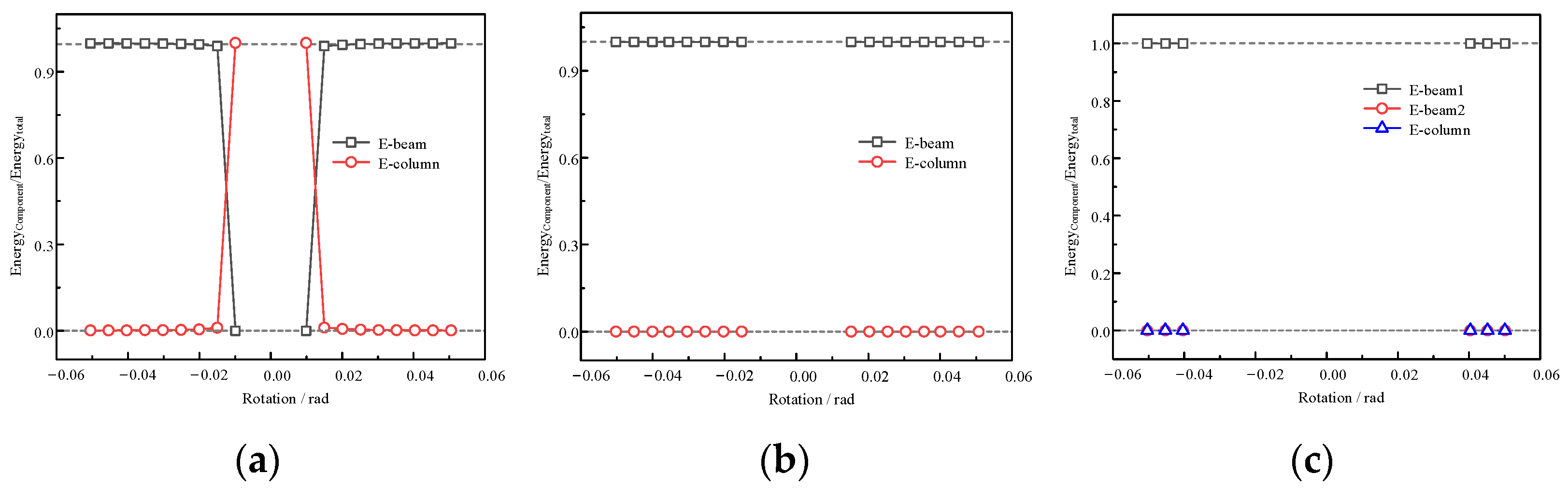
Figure 18 shows that the W-RBS joint dissipates plastic energy predominantly through the beam component, while the column contribution remains negligible throughout the loading history, indicating that the inelastic demand is intentionally shifted away from the column. A similar trend is observed for the Bolted joint under the present component partition, where the column set remains essentially elastic and the plastic dissipation is mainly recorded in the beam set. In contrast, the Prefab-web-fuse joint exhibits a clear dissipation localization mechanism: once plasticity is activated, the cumulative plastic dissipation is almost entirely concentrated in the designated replaceable fuse segment (Beam1), whereas both the non-fuse beam segment (Beam2) and the column contribute marginally. This energy-partition evidence provides direct quantitative support for the reparability-oriented design goal: irreversible damage is preferentially confined to the replaceable component, thereby reducing plastic demand on the primary frame members and facilitating post-event repair or replacement.
Figure 18.
Cumulative plastic dissipation energy fractions of predefined component sets versus rotation amplitude for (a) W-RBS, (b) Bolted, and (c) Prefab-web-fuse, where Beam1 denotes the replaceable fuse segment and Beam2 denotes the remaining non-fuse beam segment in the prefabricated joint.
Based on Abaqus ALLPD outputs, the W-RBS joint shows a beam-dominated plastic dissipation pattern with a negligible column share (rcol ≈ 0.001 at θ = 0.05 rad), while the Bolted joint remains elastic in the column set under the present partition (rcol ≈ 0).
For the Prefab-web-fuse joint, the cumulative plastic dissipation is fully concentrated in the designated replaceable fuse segment (rfuse ≈ 1.0 at θ = 0.04–0.05 rad), whereas both the non-fuse beam segment and the column contribute marginally, demonstrating effective protection of the primary frame members.
Combining the ALLPD partition and contour snapshots, the three joints can be ranked in reparability as Prefab-web-fuse > Bolted > W-RBS, where the prefabricated fuse provides the clearest “damage-in-replaceable-part” mechanism.
5.5. Reparability-Oriented Damage Localization Evidenced by Contour Plots
Figure 19 compares contour snapshots of the three joint archetypes at the target deformation level. For the W-RBS joint (Figure 19a), the high-demand region spreads along the reduced beam section and adjacent beam segments, indicating that inelastic demand is likely to be imposed on the primary beam member. Such a distributed damage pattern, while beneficial for energy dissipation, typically implies repair actions at the member level (e.g., cutting and re-welding or replacing beam segments), which is less favorable for rapid post-event recovery.
Figure 19.
Representative von Mises stress (S, Mises) contour snapshots of the three joint archetypes at the target rotation level under monotonic loading: (a) W-RBS; (b) Bolted; (c) Prefab-web-fuse. Contours are plotted at θ = 0.05 rad. A unified color scale is used for direct comparison (unit: MPa).
For the Bolted joint (Figure 19b), the demand is mainly concentrated around the assembled interface near the beam-column connection, while the beam away from the interface remains at a low stress level. This suggests that damage and potential sliding/frictional effects are largely confined to the connection region, enabling repair strategies that focus on connection components (e.g., bolt replacement/re-tightening or interface plate replacement), rather than major intervention on the primary members.
In contrast, the Prefab-web-fuse joint (Figure 19c) exhibits a pronounced localization of demand within the intentionally weakened, replaceable web-reduced fuse segment, whereas the main beam and column remain at substantially lower demand levels. This observation is consistent with the ALLPD-based energy partition results, and it provides complementary evidence that the prefabricated fuse concept can protect the primary frame members by forcing damage to concentrate in a replaceable component, thereby enhancing reparability and accelerating functional recovery after cyclic loading events.
5.6. Residual Rotation
Residual rotation is reported to reflect post-event functionality. For each target rotation amplitude θi, the residual rotation is defined as the rotation intercept at M = 0 on the unloading branch after unloading from the corresponding peak rotation. The positive and negative residuals (θres+ and θres−) are extracted from the two unloading branches, and an averaged value is reported as = (|θres+| + |θres−|)/2. As summarized in Table 6, increases markedly with rotation amplitude for W-RBS, reaching about 0.030 rad at θ = 0.05 rad, indicating significant irrecoverable rotation demand associated with plastic hinge development. The bolted connection exhibits a moderate residual rotation (≈0.0064 rad at θ = 0.05 rad), while the Prefab-web-fuse shows a much smaller residual rotation (≈3.5 × 10⁻⁴ rad at θ = 0.05 rad) under the present configuration, suggesting better re-centering at the connection level within the investigated range.
Table 6.
Residual rotation at each target rotation amplitude.
6. Mechanism Interpretation and Design Implications
6.1. Load Transfer Paths and Plastic Hinge Control
The three joint archetypes exhibit distinct load-transfer mechanisms, which govern their strength mobilization, pinching characteristics, and the localization of inelastic demand. For the W-RBS joint, the reduced beam section intentionally shifts the peak flexural demand away from the column face and promotes a stable plastic hinge within the weakened beam segment. This deliberate “beam-hinge” mechanism explains its rapid strength mobilization and large hysteretic energy dissipation, as the dominant inelastic action is flexure-driven and develops over a relatively extended beam region.
The monotonic stress fields at θ = 0.05 rad (Figure 12) already indicate where demand concentrates for each archetype, which is consistent with the cyclic observations of pinching and dissipation localization.
For the Bolted joint, the transfer of moment and shear relies on assembled interfaces and bolt-group actions. Compared with welded continuity, the presence of bolted interfaces may introduce local compliance associated with bolt-hole bearing, interface separation/closure, and potential micro-slip, which collectively contributes to a pinched hysteresis shape and reduced energy dissipation. Meanwhile, the inelastic demand is less likely to spread into the column when the connection remains the governing region, consistent with the beam-dominated dissipation partition observed under the present component-set definition.
The Prefab-web-fuse joint modifies the load path by introducing a deliberately weakened, replaceable web-reduced segment. Once activated, the force transfer concentrates in the fuse region, and plastic dissipation is intentionally confined to this component, as supported by the ALLPD energy partition and the stress contour snapshots. This mechanism can protect the main beam and column members by limiting irreversible demand outside the fuse; however, its activation threshold depends on fuse geometry and may be delayed if the fuse is comparatively strong or short, which explains the nearly elastic response and limited energy dissipation observed at moderate rotations in the current configuration.
6.2. Trade-Offs and Selection Map
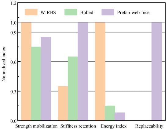
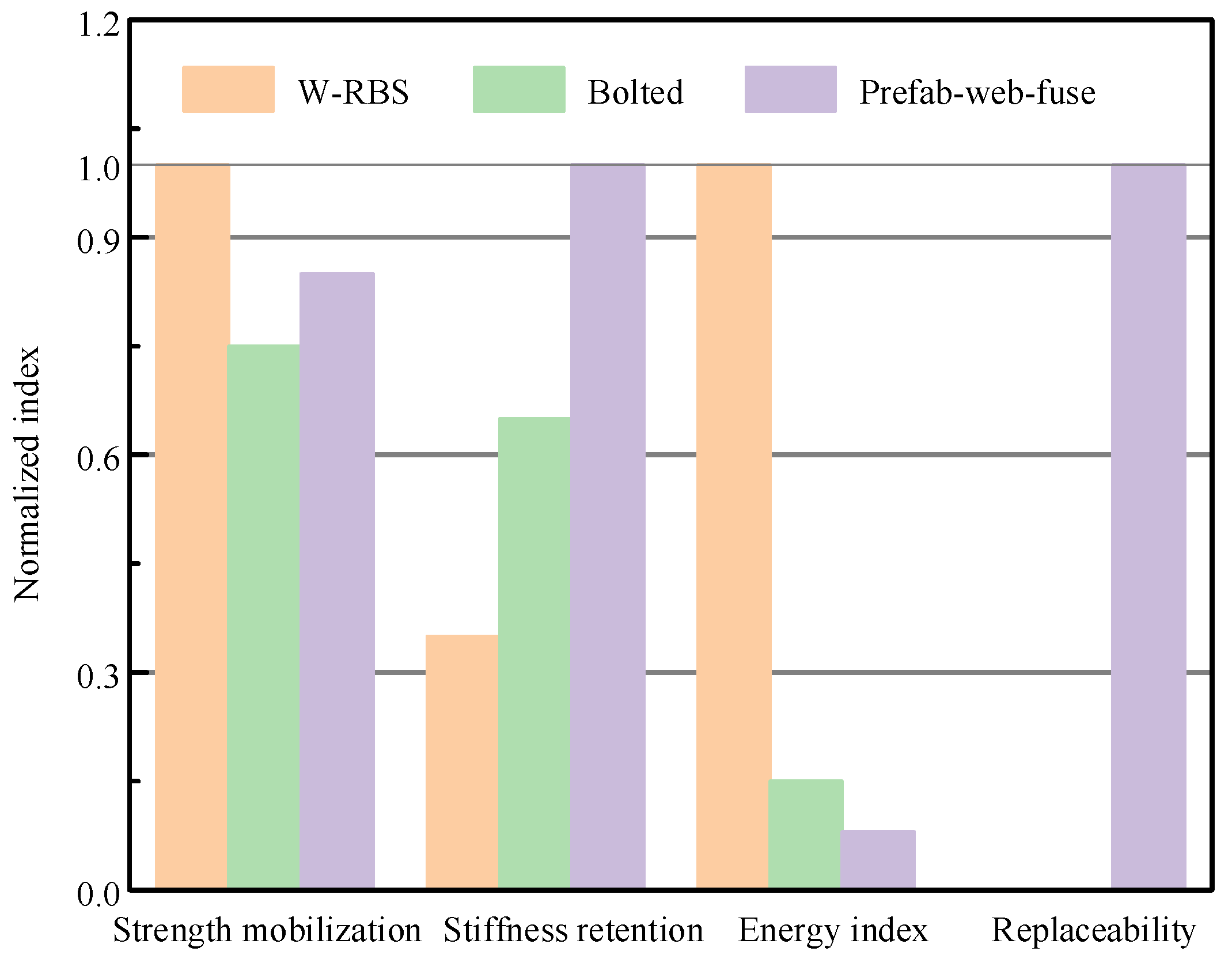
The comparative results highlight a clear trade-off among strength, stiffness stability, energy dissipation, and reparability-oriented damage localization. The W-RBS joint delivers the highest strength and the largest hysteretic energy dissipation, but it also exhibits the most pronounced stiffness degradation, reflecting sustained inelasticity in the beam region. The Bolted joint provides an intermediate solution with construction and replaceability advantages at the connection level, yet its cyclic response is more pinched and its energy dissipation indices remain considerably lower than those of W-RBS. The Prefab-web-fuse joint most effectively localizes inelastic demand into a replaceable component, offering the strongest evidence for main-frame protection and reparability; nevertheless, its current fuse configuration results in lower absolute strength and limited energy dissipation within moderate rotation demands.
For practical decision-making, a normalized performance map is recommended (Figure 20), in which each archetype is assessed by a consistent set of dimensionless indices, such as: (i) normalized strength at the target rotation, ; (ii) normalized stiffness retention, ; (iii) normalized hysteretic energy index, and (iv) damage-localization ratio based on ALLPD partition (e.g., for Type-3, and beam-dominance for Types 1–2). In general, if the design priority is maximum energy dissipation and strength, W-RBS is preferable; if rapid construction and connection-level intervention are prioritized under moderate energy demand, the bolted solution is attractive; and if reparability and main-frame protection dominate the design objective, the prefabricated fuse concept becomes the most compelling choice.
Figure 20.
Normalized performance map for decision-making among joint archetypes at θ = 0.05 rad. All indices are normalized with respect to the best-performing value among the three archetypes for each metric and are dimensionless.
6.3. Detailing Recommendations for Type 3 (Prefab-Web-Fuse)
The present results indicate that the reparability-oriented web-fuse concept is effective in confining plastic dissipation into the replaceable segment, but its performance is sensitive to detailing parameters that control the fuse activation threshold and the prevention of unintended load bypass. Three practical recommendations are highlighted.
- (1)
- Avoid load bypass: The surrounding beam flanges and adjacent stiffeners should be detailed to avoid alternative high-stiffness load paths that could bypass the web-fuse region. Clear load-transfer continuity through the fuse segment should be maintained such that the intended weakened web governs the inelastic demand.
- (2)
- Ensure fuse yields prior to main members: The fuse geometry (reduction ratio, fuse length, and cut-out configuration) should be tuned to initiate stable yielding at moderate rotations while keeping the main beam and column largely elastic. If earlier activation is desired, a larger reduction ratio, a longer effective fuse length, or refined cut-out shapes with appropriate radii can be adopted, provided that local stress concentrations are controlled.
- (3)
- Bolt layout and panel proportions: The bolt-group arrangement and the plate proportions should be selected to ensure sufficient shear transfer capacity and to suppress premature local failures at bolt holes or interfaces. A symmetric bolt layout with adequate edge distances and thicknesses is recommended to stabilize the cyclic response and to preserve the replaceability of the fuse component under repeated loading.
7. Conclusions
A controlled finite-element (FE) study was conducted to compare three beam-to-column joint archetypes (W-RBS, Bolted, and Prefab-web-fuse) under consistent member properties, interface settings, and loading/response definitions. Based on monotonic and cyclic M-θ responses, normalized performance indices, von Mises stress-field evidence, and ALLPD-based component-wise dissipation partition, the following conclusions are drawn:
- (1)
- Under identical beam/column member sections and steel material properties, the three joint concepts exhibit inherently different capacity levels due to distinct force-transfer mechanisms. Defining Mmax as the monotonic moment at θ = 0.05 rad provides a consistent reference for normalization and cross-type comparison.
- (2)
- W-RBS achieves the highest strength and the most stable/full hysteresis loops, resulting in the largest hysteretic energy dissipation. This advantage is accompanied by pronounced stiffness degradation, consistent with the distributed high-demand region along the reduced beam segment observed in the monotonic stress contours.
- (3)
- The Bolted joint shows a pinched cyclic response with substantially lower hysteretic energy and equivalent viscous damping than W-RBS. Stress-field evidence indicates that demand is mainly governed by the assembled interface region, highlighting the dominant role of interface compliance and contact-related mechanisms in its cyclic characteristics.
- (4)
- The Prefab-web-fuse joint, in the current configuration, exhibits low hysteretic energy dissipation within the investigated rotation range while maintaining nearly constant stiffness. Despite its lower absolute capacity, it demonstrates the clearest repairability-oriented mechanism: ALLPD-based dissipation concentrates essentially in the replaceable fuse segment, whereas the main beam/column members contribute marginally, supporting a “protect-and-replace” strategy.
- (5)
- The ALLPD-based energy partition, together with monotonic von Mises stress localization, provides a quantitative and visual basis to evaluate damage concentration and main-frame protection. In terms of repairability-oriented damage localization, the three joints can be ranked as Prefab-web-fuse > Bolted > W-RBS.
- (6)
- A normalized performance map is proposed to support practical selection and trade-off interpretation: W-RBS is preferable when strength and energy dissipation are prioritized; Bolted assembly provides an intermediate option with construction advantages but limited dissipation due to pinching; and the prefabricated fuse concept is most attractive when rapid repair via component replacement and main-frame protection dominate the design objective.
- (7)
- For the prefabricated web-fuse concept, improved energy dissipation at moderate rotations may be achieved by tuning fuse parameters (e.g., reduction ratio, effective fuse length, and cutout geometry) while maintaining load-path integrity to avoid unintended bypassing of the fuse.
Limitations
This study is intended as a controlled, mechanism-oriented finite-element benchmarking of three representative beam-to-column connection archetypes under a unified evaluation setting. The main limitations are summarized as follows.
- (1)
- Steel cyclic constitutive behavior is represented with isotropic hardening; more advanced cyclic models (e.g., combined isotropic-kinematic hardening) and low-cycle fatigue/fracture modeling are left for future work.
- (2)
- Note that friction coefficient and bolt pretension may affect pinching and energy dissipation of assembled joints; in this study, standard-based values are adopted and kept identical across the assembled archetypes to ensure a fair comparative baseline. Pretension loss/relaxation and potential changes in friction conditions are not explicitly modeled and will be examined in future work together with interface-parameter sensitivity and experimental calibration.
- (3)
- In this study, “repairability” is assessed from a damage-localization and replaceability perspective, quantified by component-wise plastic dissipation partition and supported by stress localization patterns within the investigated rotation range. Since fracture/low-cycle fatigue is not modeled, the results are not intended to predict crack initiation/propagation, bolt fracture, or fracture-controlled ultimate rotation capacity beyond the imposed deformation demand.
- (4)
- The comparison is conducted for a single set of member sizes/material properties and a prescribed loading protocol/target rotation level. While the proposed normalized indices are dimensionless, their quantitative values may vary under different geometries, materials, and loading protocols; therefore, they should be interpreted as benchmarking measures within the unified setting of this study rather than universal constants.
- (5)
- The present web-fuse configuration is adopted as a representative benchmark rather than an optimized final design; systematic tuning/optimization of fuse geometry parameters (reduction ratio, effective fuse length, and cutout shape) will be pursued in future work.
- (6)
- The study focuses on connection/subassembly-level response; system-level effects (e.g., gravity framing interaction, building-level P-Δ effects, and global residual drift) are not explicitly assessed.
Future work will focus on strengthening the experimental basis and extending the applicability of the proposed metrics. First, broader experimental calibration/validation against published or newly conducted cyclic tests for representative welded, bolted, and fuse-enabled connections will be pursued. Second, more advanced cyclic steel constitutive models (e.g., combined isotropic-kinematic hardening) together with fracture/low-cycle fatigue criteria will be incorporated to better capture post-peak deterioration and failure modes. Third, systematic parameter studies on key interface and detailing variables (e.g., friction conditions, pretension loss/relaxation, target rotation demand, and fuse geometry) will be conducted to establish robust design ranges. Finally, the current subassembly-level findings will be extended to frame-level simulations to evaluate residual drift, replaceability-oriented repair actions, and functional recovery implications.
Author Contributions
Author Contributions: Conceptualization, Y.W., F.Z. and H.X.; methodology, Y.W.; software, Y.W.; validation, Y.W., S.Z., F.Z. and M.T.; formal analysis, Y.W.; investigation, Y.W.; resources, F.Z.; writing—original draft preparation, Y.W.; writing—review and editing, S.Z., F.Z., H.X. and D.L.; supervision, H.X.; funding acquisition, D.L. All authors have read and agreed to the published version of the manuscript.
Funding
This research was funded by the China Post-doctoral Science Foundation Funded Project Grant No. 2024M753652.
Institutional Review Board Statement
Not applicable.
Informed Consent Statement
Not applicable.
Data Availability Statement
The data supporting the findings of this study are available from the corresponding author upon reasonable request.
Acknowledgments
The authors gratefully acknowledge the support from their institution and colleagues for helpful discussions and technical assistance related to finite-element modeling and result post-processing.
Conflicts of Interest
Authors Yao Wang, Shufeng Zhang, Feng Zhang, Minjie Tu and Hongguang Xu were employed by the company CSCEC Strait Construction and Development Co., Ltd. The remaining authors declare that the research was conducted in the absence of any commercial or financial relationships that could be construed as a potential conflict of interest.
Abbreviations
The following abbreviations are used in this manuscript:
| W-RBS | Welded reduced beam section connection |
| MRFs | Steel moment-resisting frames |
| RBS | Reduced beam section |
| M-θ | Moment-rotation |
| FE | Finite-element |
| RP | Reference point |
| M | Connection moment |
References
- Bruneau, M.; Chang, S.E.; Eguchi, R.T.; Lee, G.C.; O’Rourke, T.D.; Reinhorn, A.M.; Shinozuka, M.; Tierney, K.; Wallace, W.A.; Von Winterfeldt, D. A framework to quantitatively assess and enhance the seismic resilience of communities. Earthq. Spectra 2003, 19, 733–752. [Google Scholar] [CrossRef] [Scilit]
- FEMA 350; Recommended Seismic Design Criteria for New Steel Moment-Frame Buildings. Federal Emergency Management Agency: Washington, DC, USA, 2000.
- FEMA 355C; State of the Art Report on Systems Performance of Steel Moment Frames Subject to Earthquake Ground Shaking. Federal Emergency Management Agency: Washington, DC, USA, 2000.
- FEMA. FEMA Seismic Performance Assessment of Buildings, 2nd ed.; FEMA P-58-1; Volume 1—Methodology; Federal Emergency Management Agency: Washington, DC, USA, 2018.
- Pampanin, S. Towards the “ultimate earthquake-proof” building: Development of an integrated low-damage system. In Perspectives on European Earthquake Engineering and Seismology; Springer International Publishing: Cham, Switzerland, 2015; Volume 2, pp. 321–358. [Google Scholar]
- ANSI/AISC 341-22; Seismic Provisions for Structural Steel Buildings. American Institute of Steel Construction: Chicago, IL, USA, 2022.
- ANSI/AISC 358-22; Prequalified Connections for Special and Intermediate Steel Moment Frames for Seismic Applications. American Institute of Steel Construction: Chicago, IL, USA, 2022.
- Ribeiro, T.; Bernardo, L.; Carrazedo, R.; De Domenico, D. Seismic design of bolted connections in steel structures—A critical assessment of practice and research. Buildings 2022, 12, 32. [Google Scholar] [CrossRef] [Scilit]
- CEN EN 1993-1-8:2005; Eurocode 3: Design of Steel Structures—Part 1–8: Design of Joints. European Committee for Standardization: Brussels, Belgium, 2005.
- CEN EN 1998-1:2004; Eurocode 8: Design of Structures for Earthquake Resistance—Part 1: General Rules, Seismic Actions and Rules for Buildings. European Committee for Standardization: Brussels, Belgium, 2004.
- Shi, G.; Shi, Y.; Wang, Y. Behaviour of end-plate moment connections under earthquake loading. Eng. Struct. 2007, 29, 703–716. [Google Scholar] [CrossRef] [Scilit]
- FEMA 461; Interim Testing Protocols for Determining the Seismic Performance Characteristics of Structural and Nonstructural Components. Federal Emergency Management Agency: Washington, DC, USA, 2007.
- Latour, M.; Piluso, V.; Rizzano, G. Free from damage beam-to-column joints: Testing and design of DST connections with friction pads. Eng. Struct. 2015, 85, 219–233. [Google Scholar] [CrossRef] [Scilit]
- Boushehri, K.; Tsavdaridis, K.D.; Cai, G. Seismic behaviour of RWS moment connections to deep columns with European sections. J. Constr. Steel Res. 2019, 161, 416–435. [Google Scholar] [CrossRef] [Scilit]
- Davarpanah, M.; Ronagh, H.; Memarzadeh, P.; Behnamfar, F. Cyclic behaviour of elliptical-shaped reduced web section connection. Structures 2020, 24, 955–973. [Google Scholar] [CrossRef] [Scilit]
- He, X.; Ke, K.; Chen, Y.; Yam, M.C.; Shao, T. An experimental study of steel-concrete composite connections equipped with fuse angles. J. Constr. Steel Res. 2022, 195, 107357. [Google Scholar] [CrossRef] [Scilit]
- Chen, P.; Pan, J.; Hu, F.; Wang, Z. Numerical investigation on seismic resilient steel beam-to-column connections with replaceable buckling-restrained fuses. J. Constr. Steel Res. 2022, 199, 107598. [Google Scholar] [CrossRef] [Scilit]
- Christopoulos, C.; Filiatrault, A. Principles of Passive Supplemental Damping and Seismic Isolation; IUSS Press: Rome, Italy, 2006. [Google Scholar]
- Guo, Y.; Wang, M. Experimental study on mechanical behavior and resilient performance of steel frame connection with low-yield-point steel fuses. Eng. Struct. 2022, 266, 114599. [Google Scholar] [CrossRef] [Scilit]
- Tartaglia, R.; D’Aniello, M.; Landolfo, R. Response of Seismically Damaged Steel Reduced Beam Section Joints under Fire. Appl. Sci. 2023, 13, 3641. [Google Scholar] [CrossRef] [Scilit]
- Wang, Y.; Wang, Z.; Pan, J.; Wang, P.; Qin, J.; Chen, S. Cyclic behavior of anchored blind-bolted extended end-plate joints to cfst columns. Appl. Sci. 2020, 10, 904. [Google Scholar] [CrossRef] [Scilit]
- Cho, B.H.; Lee, J.S.; Kim, H.; Kim, D.-J. Structural performance of a new blind-bolted frame modular beam-column connection under lateral loading. Appl. Sci. 2019, 9, 1929. [Google Scholar] [CrossRef] [Scilit]
- Valente, M.; Castiglioni, C.A.; Kanyilmaz, A. Dissipative devices for earthquake resistant composite steel structures: Bolted versus welded solution. Bull. Earthq. Eng. 2016, 14, 3613–3639. [Google Scholar] [CrossRef] [Scilit]
- Valente, M.; Castiglioni, C.A.; Kanyilmaz, A. Numerical investigations of repairable dissipative bolted fuses for earthquake resistant composite steel frames. Eng. Struct. 2017, 131, 275–292. [Google Scholar] [CrossRef] [Scilit]
- D’Aniello, M.; Montuori, R.; Nastri, E.; Piluso, V.; Todisco, P. Parametric Finite Element Study on FREEDAM Beam to Column Joints with Different Details of the Haunch Slotted Holes. Appl. Sci. 2024, 14, 2770. [Google Scholar] [CrossRef] [Scilit]
- Colajanni, P.; Ahmed, M.; Pagnotta, S.; Orlando, P. A review of friction dissipative beam-to-column connections for the seismic design of MRFs. Appl. Sci. 2024, 14, 2291. [Google Scholar] [CrossRef] [Scilit]
- Ma, X.; Borchers, E.; Pena, A.; Krawinkler, H.; Billington, S.; Deierlein, G.G. Design and Behavior of Steel Shear Plates with Openings as Energy-Dissipating Fuses; The John A. Blume Earthquake Engineering Center: Stanford, CA, USA, 2010. [Google Scholar]
- Wang, M.; Guo, Y.; Yang, L. Damage indices and fragility assessment of coupled low-yield-point steel plate shear walls. J. Build. Eng. 2021, 42, 103010. [Google Scholar] [CrossRef] [Scilit]
- Guo, Y.; Wang, M. Resilient performance of steel connections with low yield point fuses considering the effect of RC floor slab. Structures 2023, 57, 105219. [Google Scholar] [CrossRef] [Scilit]
- Wang, M.; Guo, Y. Study on performance of coupled low yield point steel plate shear walls affected by the interaction of infill plates and boundary frame. Eng. Mech. 2020, 37, 184–198. [Google Scholar]
- Abaqus 6.11: GUI Toolkit Reference Manual; Dassault Systemes Simulia Corporation: Providence, RI, USA, 2011; Available online: http://abaqusdocs.eait.uq.edu.au/v6.11/pdf_books/GUI.pdf (accessed on 4 February 2026).
- RCSC (Research Council on Structural Connections). Specification for Structural Joints Using High-Strength Bolts; Research Council on Structural Connections: Chicago, IL, USA, 2014. [Google Scholar]
- GB/50017-2017; Standard for Design of Steel Structures. Standards Press of China: Beijing, China, 2017.

Disclaimer/Publisher’s Note: The statements, opinions and data contained in all publications are solely those of the individual author(s) and contributor(s) and not of MDPI and/or the editor(s). MDPI and/or the editor(s) disclaim responsibility for any injury to people or property resulting from any ideas, methods, instructions or products referred to in the content. |
© 2026 by the authors. Licensee MDPI, Basel, Switzerland. This article is an open access article distributed under the terms and conditions of the Creative Commons Attribution (CC BY) license.