


Featured Application
The validated composite coupling system enables the structural segmentation of small wind turbine blades compliant with IEC 61400-2 requirements, facilitating transportation, on-site assembly, maintenance operations, and modular blade replacement while maintaining structural integrity and fatigue reliability.
Abstract
The structural segmentation of wind turbine blades offers advantages in transportation, manufacturing, and maintenance; however, it introduces interfaces that may compromise load transfer and fatigue performance. This study presents the experimental and numerical validation of a composite coupling system designed for small wind turbine blades compliant with IEC 61400-2 requirements. A 2 m representative section extracted from the mid-span region of a 9 m blade was manufactured using vacuum-assisted resin infusion and tested under static loading conditions. A detailed finite element model based on classical laminate theory and orthotropic material properties was developed to predict structural response. Experimental measurements showed a maximum tip deflection of 15 mm under the applied load, compared to 13.76 mm predicted numerically, corresponding to a deviation of 8.9%. Surface strain measurements obtained from eight strain gauges installed across the blade–coupling interface indicated maximum mean values of +632.4 με in tension and −664.2 με in compression, with no evidence of localized strain amplification at the instrumented locations. These findings demonstrate that fully composite permanent segmentation can preserve stiffness continuity while maintaining strain levels below reported fatigue initiation thresholds, supporting the structural feasibility of segmented blade architectures for small wind turbine applications.
1. Introduction
The continuous increase in wind turbine blade size has imposed significant constraints related to transportation, logistics, manufacturing, and on-site installation. Segmented blades have therefore emerged as a viable technological solution, enabling modular configurations, field assembly, and enhanced supply chain flexibility [1]. The concept of segmented wind turbine blades has been extensively reviewed in the literature, highlighting both logistical advantages and structural challenges [2]. In parallel, growing demands for energy efficiency, reliability, and sustainability have motivated research efforts that combine mechanical design innovations with integrated condition monitoring and failure detection strategies [3].
Despite their advantages, segmented blade architectures introduce structural interfaces that may compromise mechanical performance if not properly designed. These interfaces can lead to stress concentrations, stiffness discontinuities, and accelerated fatigue degradation, making the development of reliable and structurally efficient joining systems a critical challenge [4]. Furthermore, emerging segmented blade concepts incorporating advanced functionalities—such as partial pitch control [5] or mass-optimized and smart blade systems [6]—require joint designs capable of accommodating complex and dynamic load transfer mechanisms without degrading structural continuity.
This study constitutes a direct continuation of the full-scale (60 m) numerical investigation presented by Santander et al. [7], in which the structural performance of a permanent composite coupling for segmented wind turbine blades was validated using finite element analysis. In the present work, experimental validation is conducted under laboratory conditions using a 2 m blade section extracted from an industrial mold of a conventional 9 m blade. The primary objective is to experimentally verify the local structural behavior of the coupling system under extreme static loading conditions, rather than to assess the global response of a complete blade.
The reduced-scale experimental approach is dictated by test bench limitations, which preclude full-length blade testing. However, this approach remains mechanically representative for the intended purpose, as the composite materials employed exhibit scale-independent elastic properties and the dominant load transfer mechanisms within composite joints are governed by material behavior and joint geometry rather than by overall blade length [8]. Since the objective of this study is to characterize local load transfer and stiffness continuity at the joint level, the reduced-scale approach is mechanically representative despite not capturing full aeroelastic blade behavior. Moreover, preserving structural continuity at segmented interfaces is essential for maintaining cross-sectional stiffness distributions, which directly influence aeroelastic performance and coupled aerodynamic–structural response [9]. Consequently, subcomponent-level experimental validation provides meaningful insight into the mechanical performance of full-scale segmented blade designs. To the authors’ knowledge, this study represents one of the few experimentally validated joint-level investigations reported in the literature of a fully composite permanent coupling manufactured using conventional industrial blade processes.
2. Materials and Methods
2.1. Test Section and Material Subsection
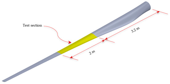
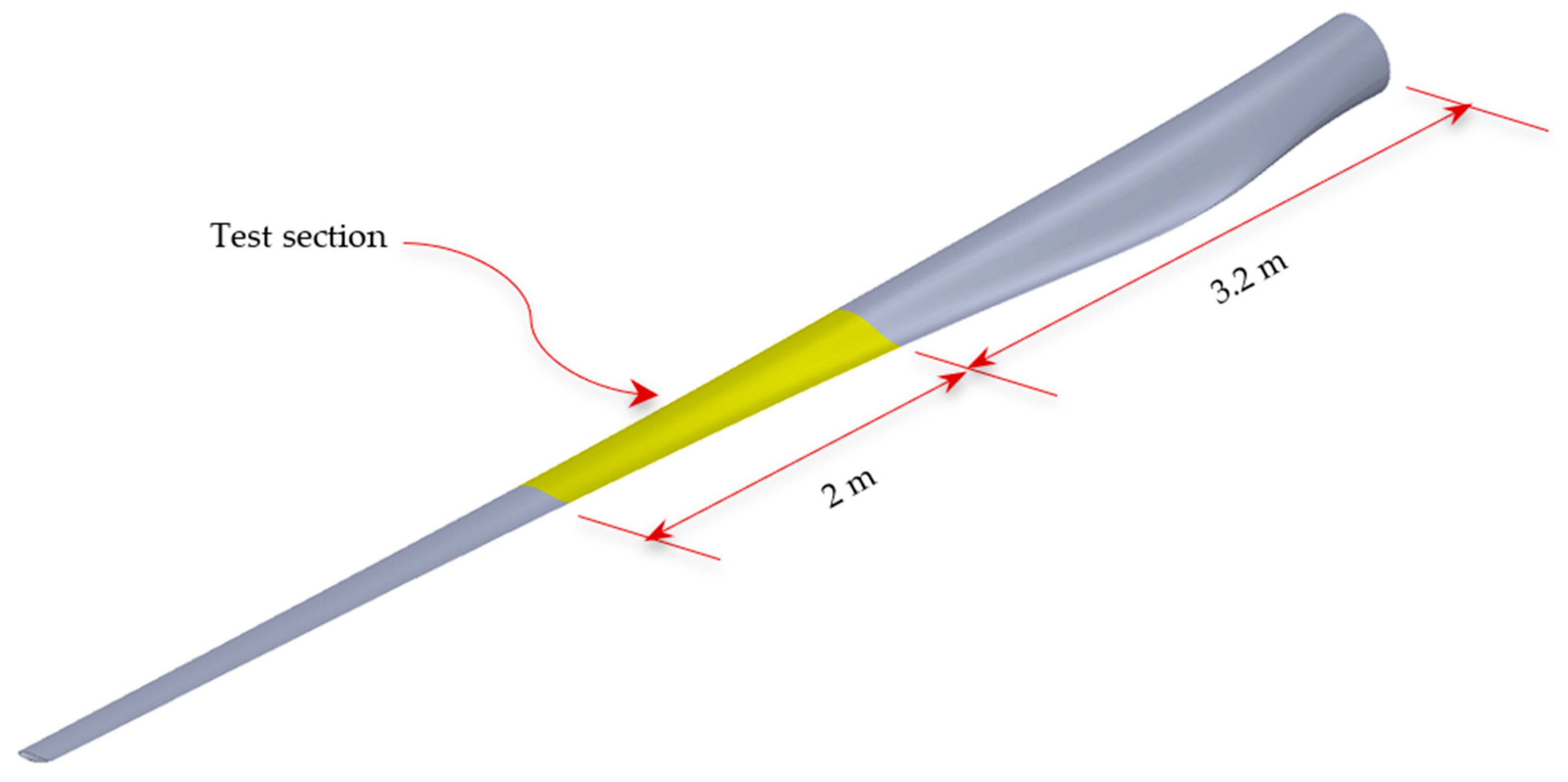
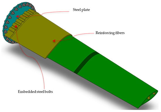
The analyzed model corresponds to a 2 m test section located in the mid-span region of a 9 m blade mold, at a radial distance of 3.2 m from the blade root (Figure 1). This location was selected due to its exposure to combined bending and shear loading conditions representative of operational service environments [10]. In addition, this section corresponds to the location where two segments of a segmented blade are joined.
Figure 1.
Conceptual representation of a segmented wind turbine blade and its main components, highlighting the permanent composite joint investigated in this study.
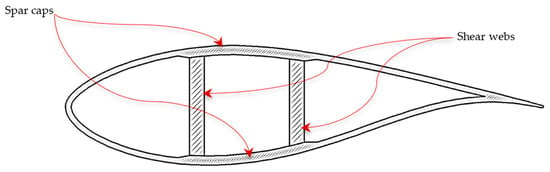
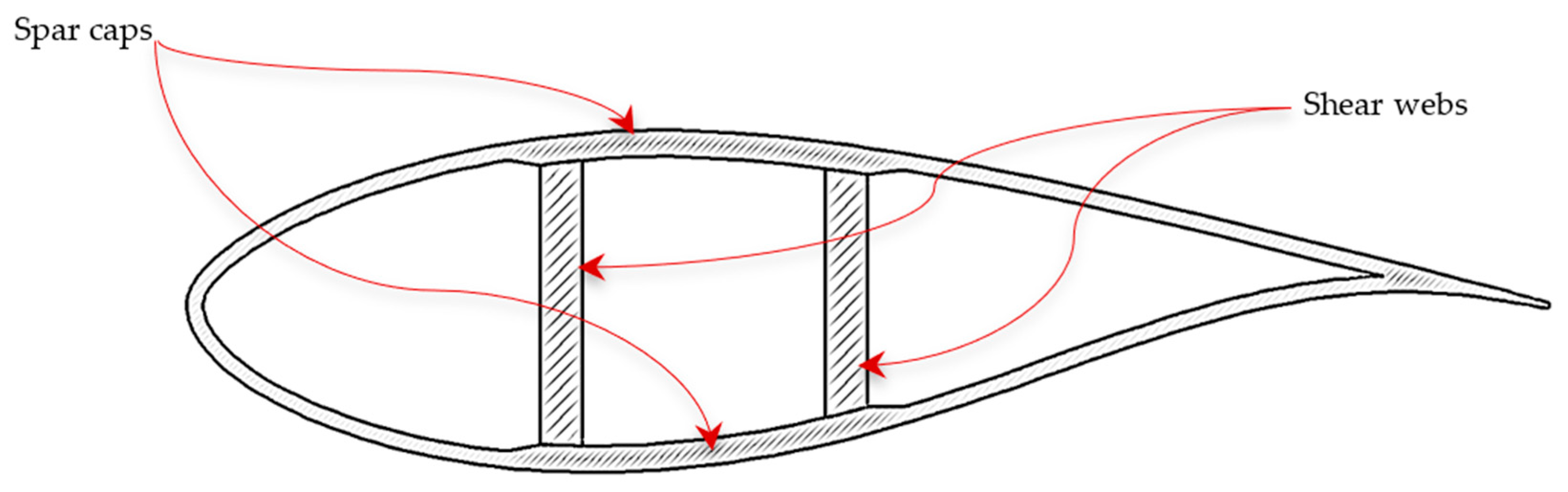
The laminate architecture follows industrial blade manufacturing standards, incorporating E-glass multiaxial fiber reinforcements and sandwich core materials optimized for stiffness-to-weight performance [11]. The selected glass fiber-reinforced polymer configuration is consistent with recent developments in composite material systems for wind turbine blade applications [12]. The structural configuration includes spar caps, shear webs, and aerodynamic shell components (Figure 2). This design strategy aligns with recent advances in polymer composite systems for wind turbines [13] and modular material optimization [14].
Figure 2.
Structural configuration of the test segment.
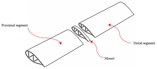
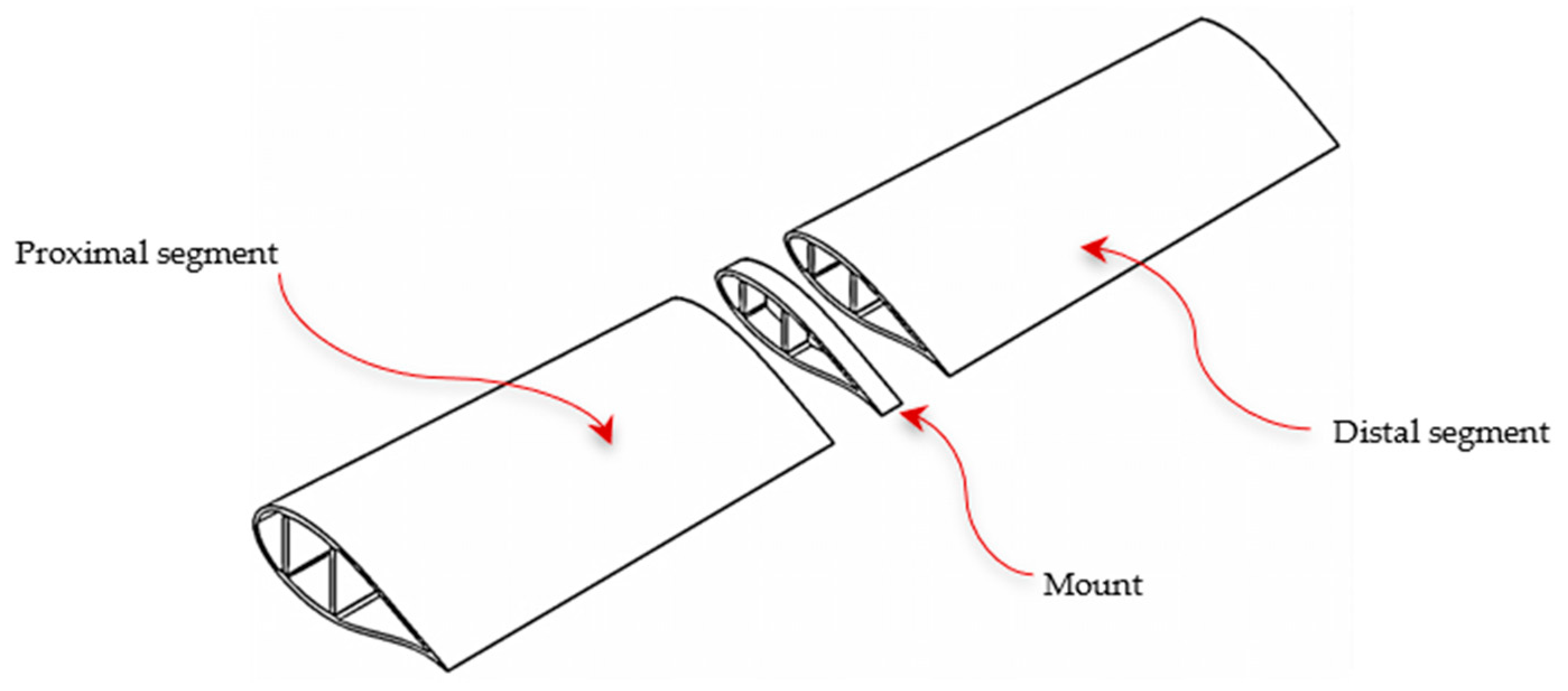
This test section represents a conventional wind turbine blade. To obtain a segmented configuration, the section was divided into three subcomponents (Figure 3). The intermediate subcomponent, referred to as the assembly segment, has a length of 50 mm and is used to create the coupling interface. The outer subcomponents correspond to the proximal segment (root side) and the distal segment (tip side).
Figure 3.
Subcomponents of the segmented test section.
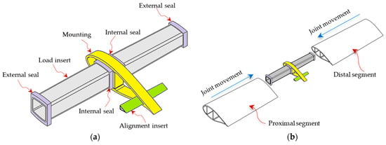
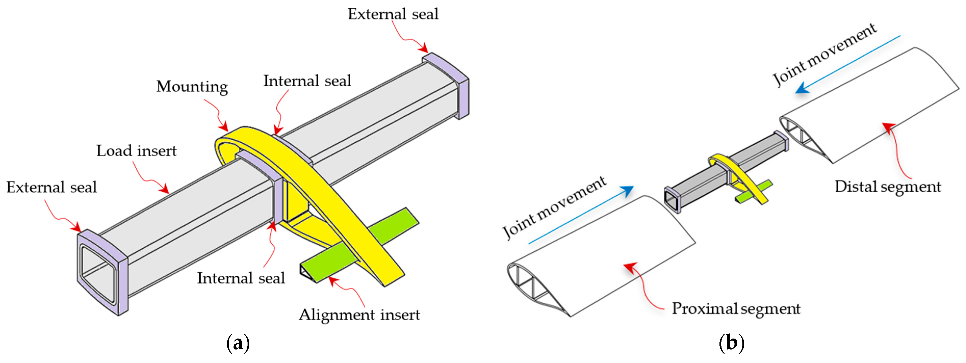
The coupling system consists of a load insert and an alignment insert integrated into the assembly segment. Both inserts are manufactured from biaxial glass fiber (BIAX) laminates comprising six plies, with a total length of 826 mm for the load insert. The process is compatible with industrial vacuum infusion techniques. Rounded longitudinal edges were incorporated into the load insert to mitigate stress concentration effects and enhance load diffusion. The load insert is bonded within the cavity formed by the spar caps and shear webs and is responsible for transferring loads from the distal to the proximal segment. The alignment insert is bonded at the trailing edge of the assembly segment and ensures correct angular alignment between segments (Figure 4).
Figure 4.
Coupling mechanism of the segmented test section: (a) coupling components; (b) joining.
The root region of the segmented test section was locally reinforced with ten layers of triaxial glass fiber (TRIAX) oriented at ±45°/0° relative to the blade longitudinal axis. Each layer had an approximate nominal thickness of 1.8 mm after resin infusion, resulting in a total reinforcement thickness of approximately 18 mm in the coupling region. Twelve embedded steel bolts were mechanically connected to a perforated steel plate, which was attached to the test bench. This configuration provided rigid boundary conditions during experimental testing (Figure 5), reproducing standardized blade testing setups and ensuring structural stability [15].
Figure 5.
Segmented test section with test fixture.
The materials, laminate architecture, and coupling geometry are identical to those employed in the full-scale study by Santander et al. [7], ensuring structural consistency between both investigations (Table 1).
Table 1.
Material properties.
2.2. Numerical Modeling
Finite element simulations were performed using ANSYS Mechanical (Release 17.0). Composite laminates were modeled using SHELL181 layered elements with orthotropic material properties, whereas metallic regions were represented by SOLID185 solid elements. Layered shell elements with orthotropic constitutive definitions were used to accurately capture composite material anisotropy. The composite laminates were modeled using layered shell formulations based on classical laminate theory, assuming linear elastic orthotropic behavior [16]. Material properties were obtained from manufacturer datasheets and cross-validated against published composite material databases [17,18].
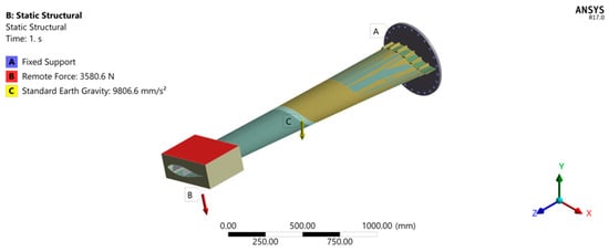
The steel plate was fully constrained in all translational and rotational degrees of freedom (Figure 6). Gravitational loading and an equivalent static bending force of 3580.6 N were applied at the blade tip. The applied boundary conditions and load cases are also aligned with internationally recognized design and testing recommendations for wind turbine rotor blades [19], complementing the IEC 61400-2 requirements [20].
Figure 6.
Boundary conditions.
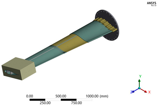
A mesh convergence study was conducted to ensure that the numerical results were independent of the element size [21]. Successive mesh refinements were performed, and convergence was evaluated by monitoring the variation in the maximum displacement at the blade tip and the strain values at the strain gauge locations. The mesh was considered converged when further refinement produced changes smaller than 3% in these response parameters. Based on this criterion, the final mesh configuration was selected as a compromise between computational efficiency and numerical accuracy. The final finite element model consisted of 84,362 SHELL181 elements used to represent the composite laminates and 109,894 SOLID185 elements used to model the metallic coupling inserts (Figure 7). Perfect bonding between the composite laminates and the metallic inserts was assumed in the numerical model.
Figure 7.
Mesh.
2.3. Manufacturing and Experimental Procedure
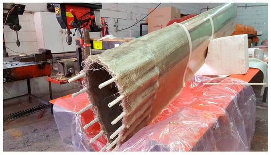
The test section was manufactured using vacuum-assisted resin infusion (VARI) in industrial-grade composite molds. The laminate stacking sequence strictly followed the numerical model configuration to ensure geometric and material consistency (Figure 8). The experimental procedure and loading protocol are consistent with standardized wind turbine blade testing guidelines for subcomponent validation, following ASTM D7290-21 [22].
Figure 8.
Unsegmented test section.
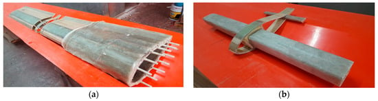
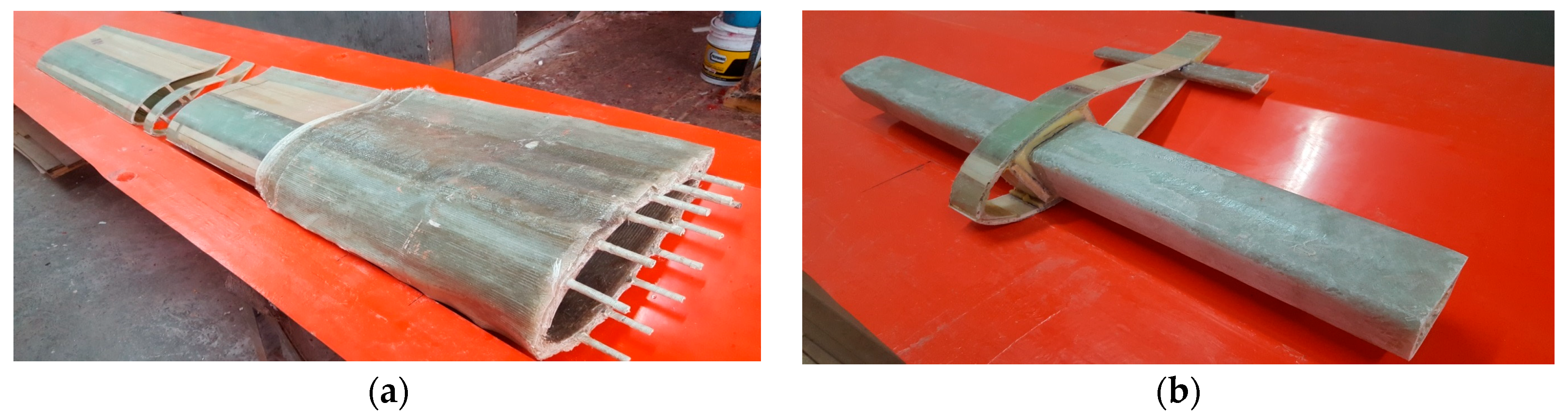
The test segment was split (Figure 9a) according to the configuration shown in Figure 3. The central portion, referred to as the assembly, was used to form the coupling by incorporating the load insert and the alignment insert, which were bonded using a high-performance structural epoxy adhesive (Figure 9b).
Figure 9.
Manufacturing of the test segment and coupling: (a) segmented test section; (b) coupling.
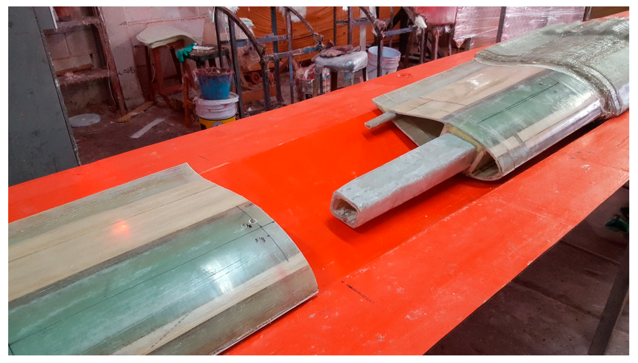
Figure 10 shows the coupling being attached to the distal segment. The load insert is positioned within the cavity formed by the spar caps and shear webs of the distal segment (Figure 2), while the alignment insert engages with the trailing-edge region of the profile. The same procedure is subsequently repeated to attach the proximal segment (Figure 9).
Figure 10.
Joining of distal and proximal segments through the coupling.
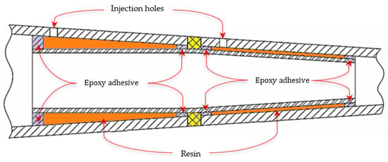
Following assembly, internal sealing and controlled resin injection were performed to establish a permanent structural interface. A schematic cross-section of the joint is shown in Figure 11.
Figure 11.
Cross-sectional schematic of the permanent joint.
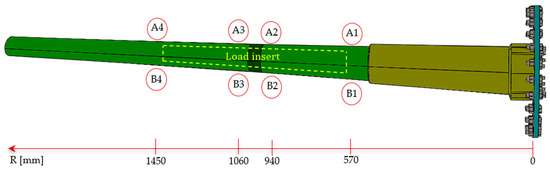
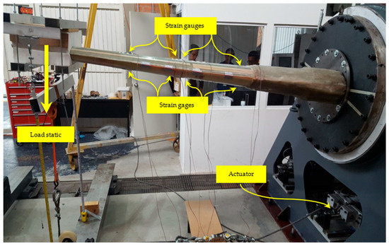
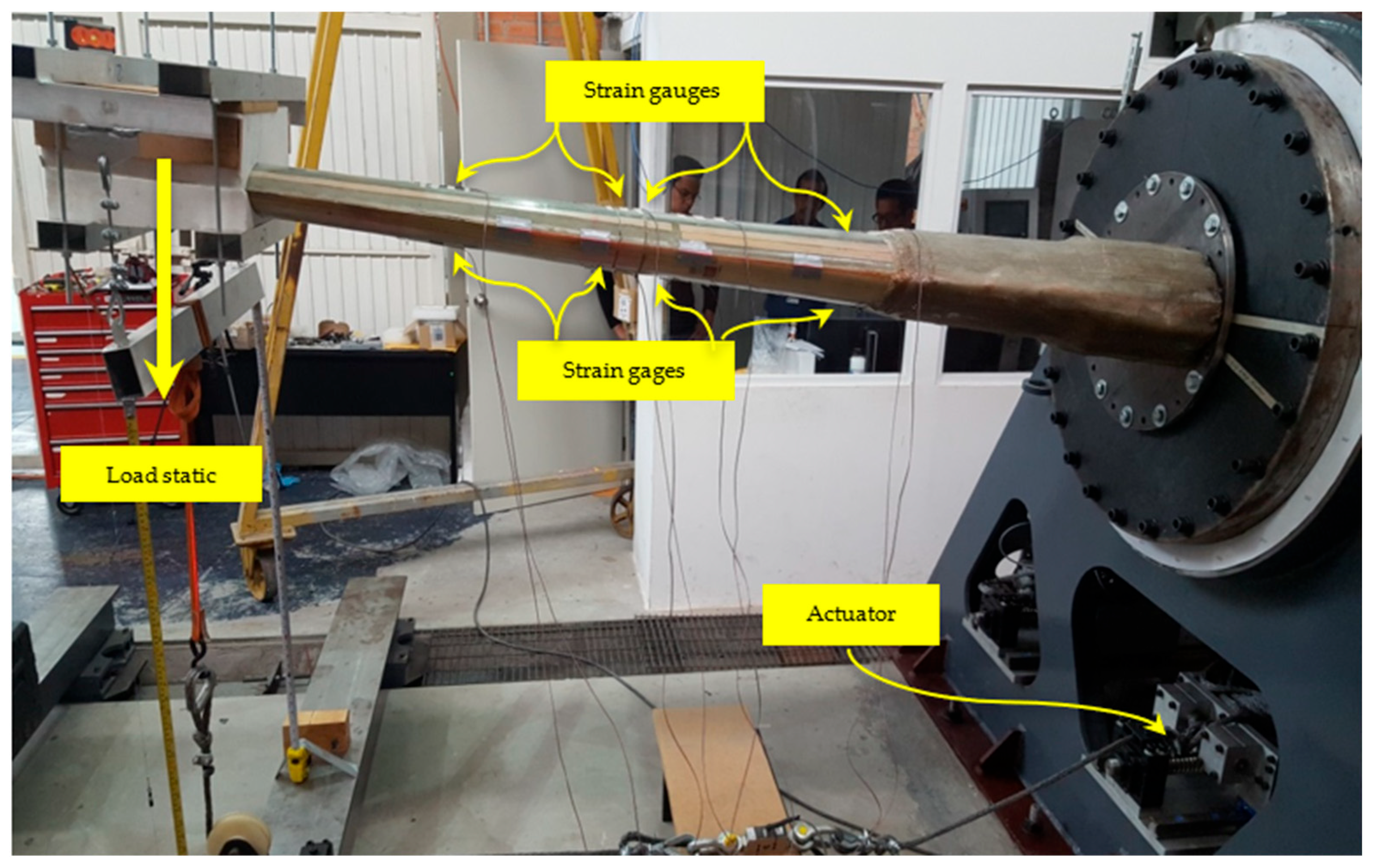
The experimental setup included instrumentation with eight uniaxial strain gauges (type CEA-06-125UWA-120, manufactured by Vishay Precision Group – Micro-Measurements, Wendell, North Carolina, USA) strategically placed on the proximal and distal segments. These locations were selected to measure strains at the beginning and end of the load insert, near the joint region, and at the center of the spar cap. Their locations and radial distances (R) are shown in Figure 12.
Figure 12.
Location of strain gauges on the segmented test section. A1–A4: pressure side; B1–B4: suction side.
Static loading was applied incrementally using a servo-hydraulic actuator. Tip deflection was recorded using a calibrated LVDT displacement transducer (model GT-1000, Sentech Inc., Willow Grove, PA, USA) (Figure 13). Three preload cycles were performed prior to the main quasi-static test. Experimental procedures followed recommended protocols for composite wind turbine blade testing [23].
Figure 13.
Segmented test section mounted on the test bench.
Prior to testing, the displacement and strain measurement systems were calibrated following the procedures recommended by the instrument manufacturers. The displacement measurement system was verified using reference measurements to ensure linear response within the expected displacement range. Strain gauges were calibrated using the standard bridge balancing procedure and verified through controlled loading prior to the experimental campaign. Based on the specifications of the measurement devices and the repeatability observed across the five experimental repetitions, the uncertainty associated with the displacement measurements is estimated to be within ±2%, while the strain measurement uncertainty is estimated to be within ±3%.
Although the experimental campaign was conducted on a reduced-scale blade subcomponent, the specimen was designed to preserve the local geometry, material configuration, and load introduction mechanisms governing the joint response. Since the objective of this study is to characterize local load transfer and stiffness continuity at the joint level, the reduced-scale approach is mechanically representative despite not capturing full aeroelastic blade behavior [24].
2.4. Use of Generative Artificial Intelligence (GenAI)
Generative artificial intelligence (GenAI) tools were used exclusively to assist with language editing, grammar refinement, and improvement of textual clarity. No AI systems were employed in the development of the experimental setup, numerical modeling, data processing, result interpretation, or scientific decision-making. All technical analyses, simulations, and experimental procedures were conducted and validated by the authors.
3. Results
3.1. Numerical Results
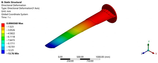
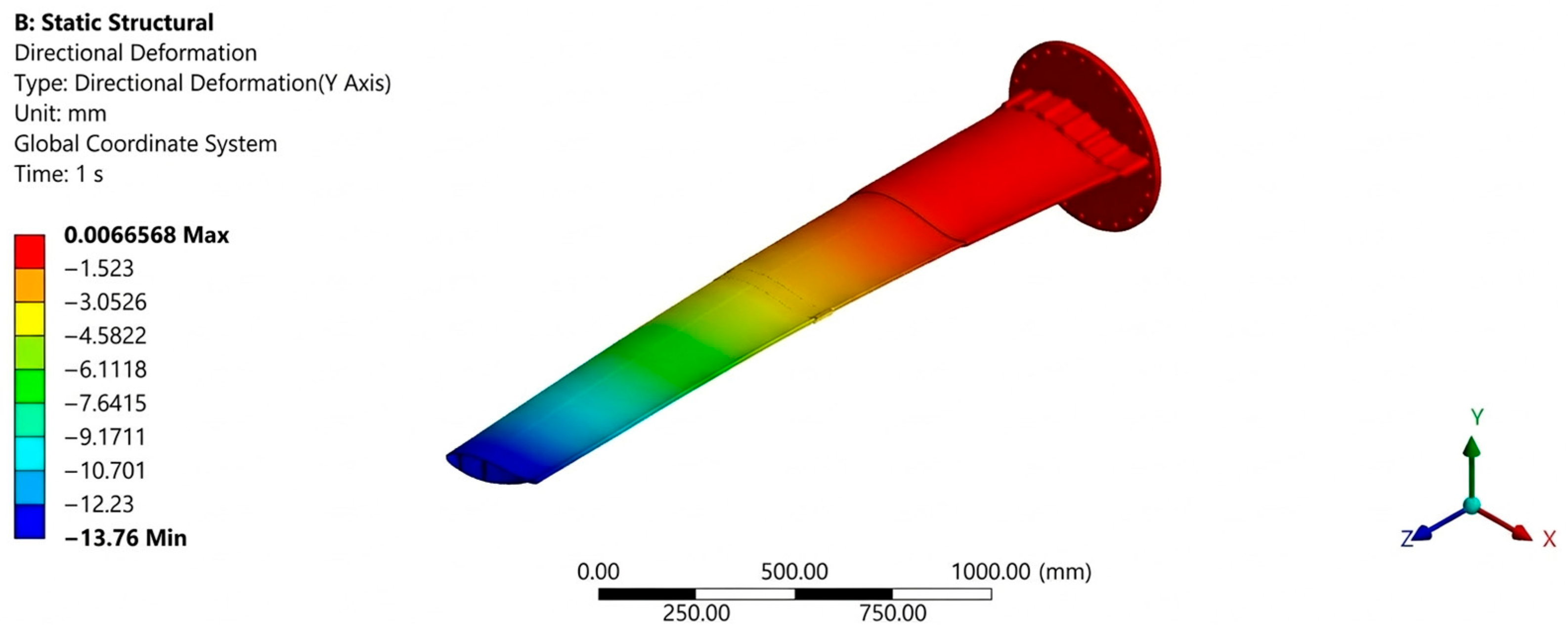
Finite element analysis under extreme IEC 61400-2 [20] loading conditions predicted a maximum blade tip deflection of 13.76 mm, demonstrating that the segmented configuration preserves global bending stiffness comparable to monolithic blade structures (Figure 14).
Figure 14.
Simulated displacement results.
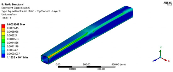
Equivalent elastic strain (as defined in ANSYS ACP Release 17.0 (post-processing) was evaluated both within the coupling inserts and at the blade–coupling interface to distinguish localized insert response from structural surface behavior. The load insert exhibited a maximum equivalent elastic strain of 3332 με, as defined by the ANSYS ACP post-processing formulation. Strain levels at the blade–coupling interface remained limited to 1174 με, indicating efficient stress redistribution and controlled load transfer mechanisms (Figure 15). It should be noted that this value corresponds to localized equivalent strain within the insert laminate (Layer-based equivalent strain in ACP), not to surface strains at the blade–coupling interface where fatigue assessment is discussed.
Figure 15.
Equivalent strain in the load insert.
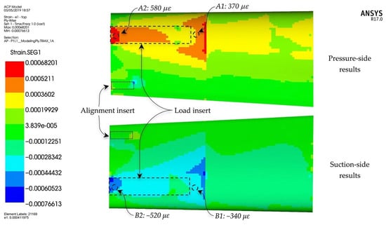
The strains in the outer glass fiber layer of the segmented test section, where the strain gauges were installed, were evaluated using ANSYS ACP (Post). Figure 16 presents the strain distribution on both the pressure and suction sides of the proximal segment. Within the load insert region (dashed box), strain values remain within the 340–580 με range in tension and −340 to −520 με in compression. The numbered strain values shown in the figure correspond to the strain gauge locations previously identified in Figure 12. The symmetric tensile–compressive distribution confirms a flexural response consistent with the applied loading configuration and indicates stable load transfer across the segmented interface.
Figure 16.
Strains in the proximal segment.
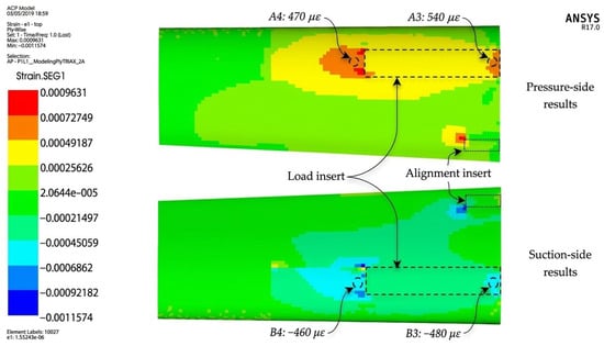
Figure 17 shows the strain distribution in the distal segment, within the load insertion region (dotted box). The strain values recorded at the calibration locations identified in Figure 12 remain within the 470–540 με range in tension and −480 to −460 με in compression, indicating a stable deformation distribution without localized amplification effects.
Figure 17.
Strains in the distal segment.
The numerical strain results were evaluated at the same locations where the strain gauges were installed during the experimental tests. Specifically, eight measurement points were defined across the blade–coupling interface, corresponding to positions A1–A4 on the proximal segment and B1–B4 on the distal segment of the blade section. These locations were selected to capture the strain distribution across the segmented interface and to allow direct comparison between numerical predictions and experimental measurements (Figure 12).
This structural behavior confirms that the coupling acts as a flexible load diffuser rather than a stress concentrator. In contrast to bolted or hybrid metallic joints reported in the literature, which often introduce abrupt stiffness discontinuities and localized damage initiation zones [15], the proposed composite coupling enables a progressive strain gradient along the segmented interface.
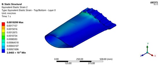
Figure 18 presents the equivalent elastic strain distribution in the blade root region (Layer 0). The results indicate that root region strains remained below approximately 1930 με under the applied static loading condition. The highest strain levels are localized near the geometric transition toward the root attachment features, while the remainder of the region exhibits a smooth strain gradient. No abrupt strain concentrations are observed, indicating that the load transfer toward the root section remains structurally controlled within the evaluated configuration.
Figure 18.
Equivalent elastic strain distribution in the blade root region.
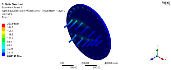
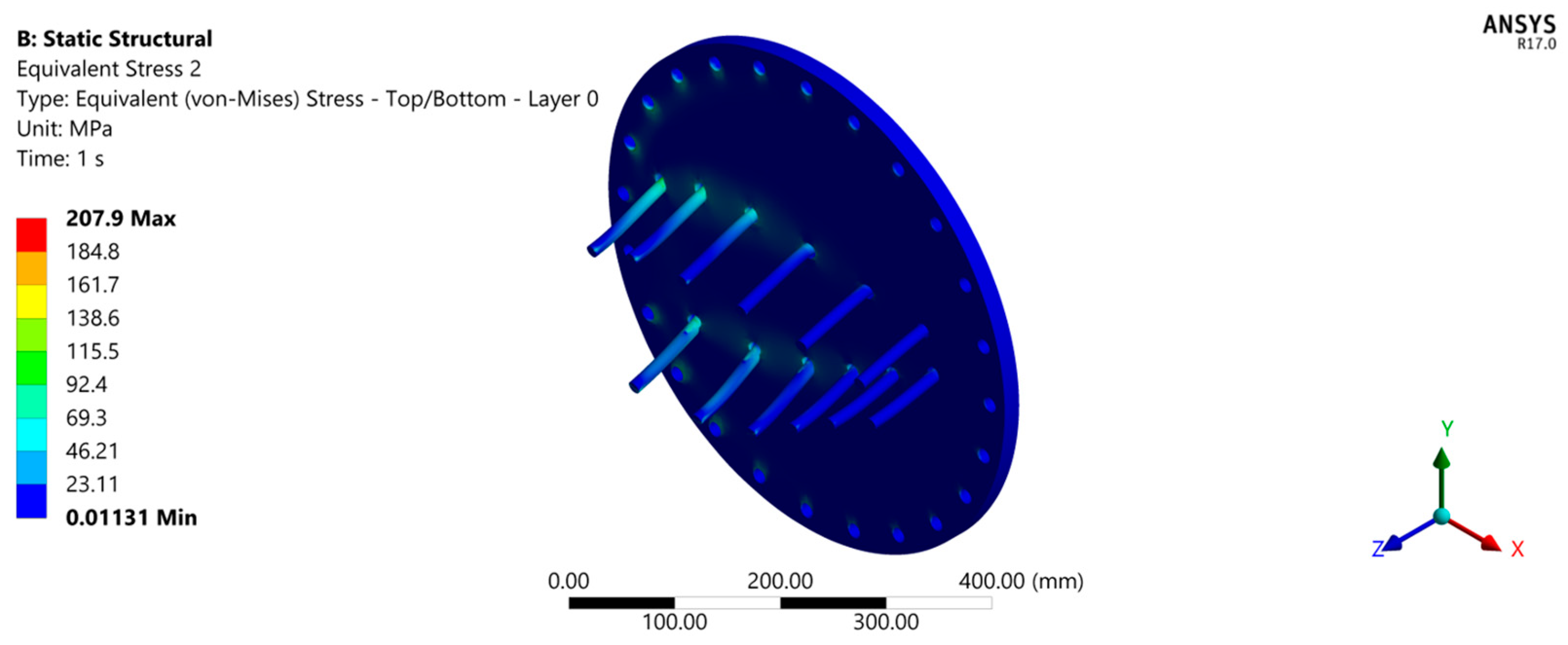
Maximum von Mises stresses in the steel reaction plate did not exceed 210 MPa (Figure 19), remaining within elastic limits. These results confirm that the imposed boundary conditions do not artificially amplify the structural response.
Figure 19.
Stress at fixation plate.
Overall, numerical results demonstrate that the permanent composite coupling maintains sectional rigidity across the segmented joint, mitigates stress concentrations, and promotes gradual stress redistribution across the interface paths, making it suitable for large-scale blade integration.
3.2. Experimental Results
Static experimental tests yielded a measured blade tip deflection of 15 mm, showing strong agreement with numerical predictions and confirming stiffness retention of the segmented assembly.
Table 2 summarizes the statistical results of the repeated strain measurements at each instrumented location. The low standard deviation observed across all strain gauges (generally below 3% of the mean value) confirms high experimental repeatability and indicates minimal measurement dispersion under repeated loading cycles. The maximum absolute strain recorded during testing was −671 με (gauge B2), while the maximum tensile peak strain reached 645 με (gauge A2). The maximum mean surface strains recorded in the coupling region reached +632.4 με in tension and −664.2 με in compression. These results support the reliability of the experimental dataset used for numerical validation.
Table 2.
Statistical summary of repeated experimental strain measurements at instrumented locations.
To evaluate the repeatability of the experimental measurements, the mean strain values and corresponding standard deviations were calculated for each strain gauge from the five repeated loading tests reported in Table 2. The relatively small dispersion observed among the repetitions indicates good consistency of the strain measurements and confirms the reliability of the experimental procedure. These averaged values were subsequently used for comparison with the numerical predictions presented in Section 3.1.
The coefficients of variation for the measured strains were below typical uncertainty levels reported for strain gauge measurements in composite structures, further supporting the reliability of the experimental data.
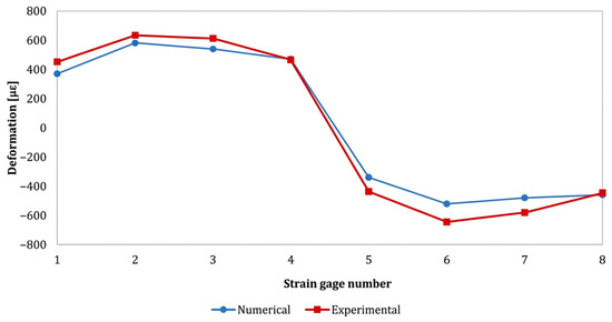
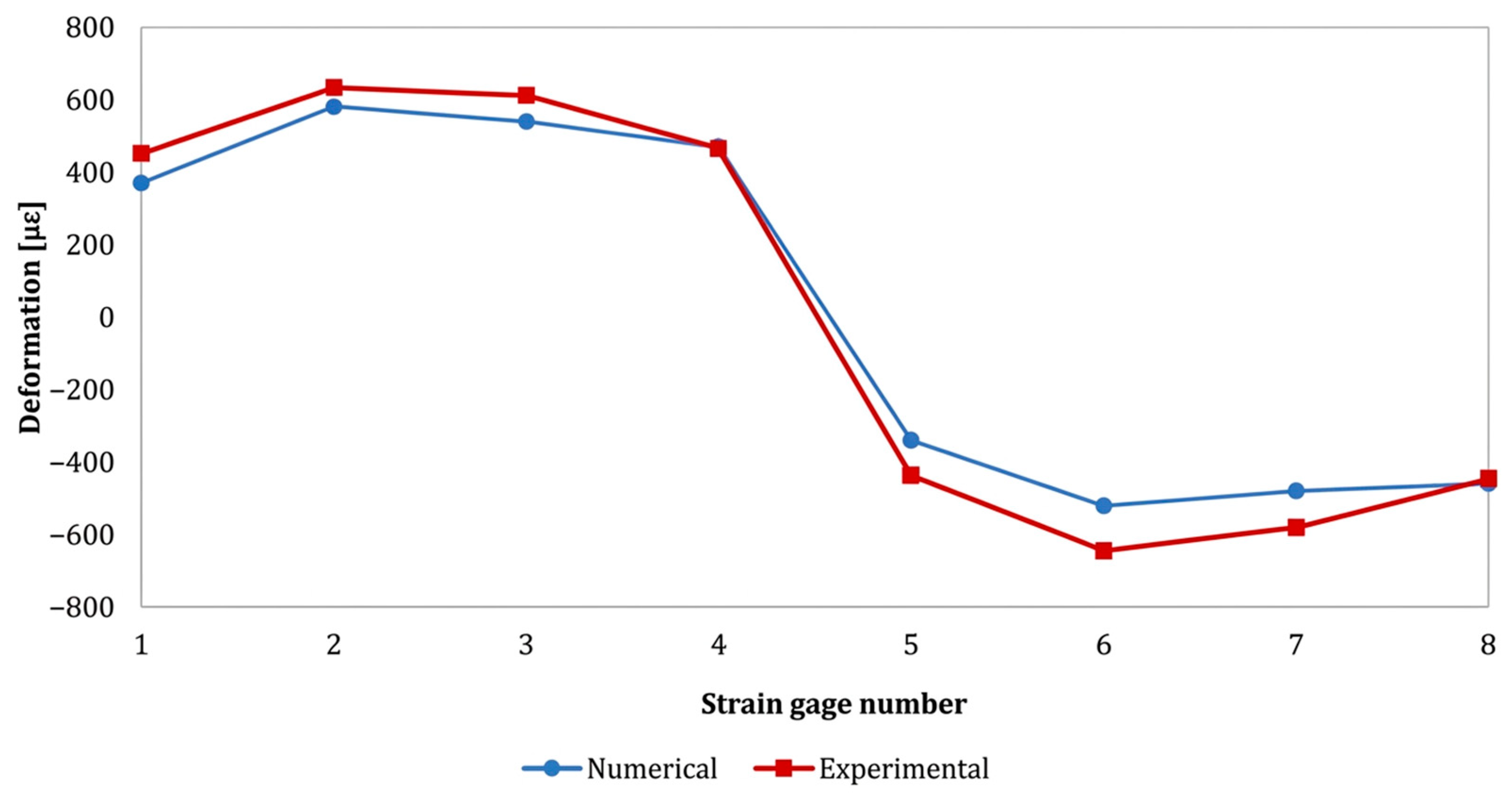
Figure 20 presents a direct comparison between finite element strain predictions and experimentally measured surface strains at the instrumented locations (Figure 12). The experimental values correspond to the mean peak strains obtained from repeated tests, as summarized in Table 2, providing a statistically representative basis for comparison with the numerical model.
Figure 20.
Comparison of numerical and experimental strain results.
Figure 20 shows the comparison between experimental and numerical strain distributions. Although a good agreement between the numerical predictions and experimental results is observed, minor discrepancies can be attributed to several factors. First, manufacturing tolerances during specimen fabrication may lead to small geometric deviations that are not fully represented in the numerical model. Second, variations in the adhesive layer thickness during the bonding process may locally modify the stiffness distribution, which can influence strain transfer and displacement response. Finally, uncertainties in the material properties used in the numerical simulations, particularly the elastic modulus and adhesive parameters, may also contribute to the observed differences. These factors are common in experimental–numerical comparisons and are considered acceptable within the uncertainty range of the measurements.
Strain distribution along the spar cap exhibited a continuous spatial gradient, indicating that the permanent composite joint does not disrupt bending load transfer mechanisms. This behavior contrasts with bolted segmented configurations, where local stiffness discontinuities frequently generate strain concentrations [25].
The applied load–displacement response remained linear throughout the loading regime, confirming elastic structural behavior and the absence of premature damage initiation. Post-test visual inspection revealed no evidence of delamination, adhesive debonding, or matrix cracking at the coupling interface.
These experimental results are consistent with recent reduced-scale blade validation studies [26], reinforcing the structural reliability of the proposed coupling architecture under realistic operational loading conditions.
Table 3 summarizes the strain ranges obtained experimentally and numerically at the strain gauge locations, enabling direct comparison between measured surface strains and finite element predictions.
Table 3.
Comparison between experimental and numerical surface strains at instrumented locations.
The numerical predictions show good agreement with the experimental surface strains, with deviations below 10%, supporting the capability of the numerical model to reproduce the structural response at the instrumented locations.
3.3. Numerical–Experimental Correlation
The discrepancy between numerical and experimental tip deflection results was limited to 8.9%, demonstrating strong correlation and validating the predictive accuracy of the numerical framework.
Comparison of numerical and experimental strain results shows good agreement in overall trends and neutral axis location. However, a systematic underestimation of strain magnitude by the numerical model was observed, with deviations consistently below 10% across instrumented locations between numerical and experimental results, more pronounced in compression regions. This deviation can be attributed to laminate thickness tolerances, variability in fiber volume fraction, adhesive bondline thickness dispersion, and uncertainty in strain gauge placement. Such discrepancies are consistent with those reported in comparable composite blade subcomponent validations [27,28].
Despite differences in absolute values, both datasets exhibit consistent stiffness trends and spatial strain distribution patterns along the spar cap, confirming that the numerical model adequately captures the dominant deformation mechanisms of the segmented assembly and supporting the validity of the previously reported full-scale numerical model [7].
3.4. Comparison with Literature
The structural performance of the proposed permanent composite coupling is evaluated in the context of recent literature on segmented wind turbine blades and joint design strategies. Numerous studies have investigated blade segmentation concepts based on bolted mechanical joints, hybrid bonded–bolted configurations, or embedded metallic interfaces. While these approaches enable modular assembly and transportation benefits, they frequently introduce stiffness discontinuities, localized stress concentrations, and increased structural complexity [1,15,25].
Table 4 provides a comparative overview of representative segmented blade joint solutions reported in the literature, considering joint concept, materials, validation approach, experimental verification at the joint level, reported strain response, and manufacturing implications. As shown in the table, most published studies rely primarily on numerical analyses or system-level conceptual assessments, with limited experimental validation focused on the joint region itself. In several cases, experimental investigations are restricted to coupon-scale or simplified joint tests, which do not fully capture the load transfer mechanisms and stiffness continuity of representative blade subcomponents.
Table 4.
Comparison of the proposed permanent composite coupling with representative segmented blade joint solutions reported in the literature.
Solutions based on metallic or hybrid interfaces, such as bolted or embedded bolt joints, commonly report local strain amplification or identify the joint region as structurally critical [15,25]. These effects are associated with abrupt stiffness transitions between dissimilar materials and often require additional local reinforcements, machining operations, or mold redesigns, increasing manufacturing complexity and potential fatigue sensitivity.
In contrast, the permanent composite coupling evaluated in this study is manufactured using the same glass fiber-reinforced polymer materials and processes as the blade structure, enabling a homogeneous load path across the segmented interface. Unlike most reported solutions, the proposed system has been validated both numerically and experimentally at the joint level using a representative blade subcomponent. Experimentally measured mean strain levels in the coupling region remained below ±700 με under extreme loading conditions defined by IEC 61400-2 [20], which is lower than the strain magnitudes explicitly reported for mechanical and hybrid joint configurations in the referenced studies. For clarity, rounded values (±700 με) are used in the discussion, while exact statistical values are reported in Table 2 and Table 3.
The results are consistent with the full-scale numerical investigation of a 60 m blade presented by Santander et al. [7], in which the same coupling concept exhibited strain levels below ±1200 με. The agreement between subcomponent experimental validation and full-scale numerical predictions supports the scalability of the proposed coupling architecture and confirms that subcomponent-level testing is sufficient to characterize the dominant joint mechanics.
From a manufacturing perspective, most alternative solutions reported in the literature require substantial modifications to existing production workflows, including drilling operations, integration of metallic components, or additional assembly steps. By contrast, the proposed permanent composite coupling can be integrated into conventional blade manufacturing lines through a single additional processing step, without altering standard lay-up or resin infusion procedures. This manufacturing compatibility represents a key advantage for industrial implementation and certification.
Overall, the comparison demonstrates that the proposed permanent composite coupling achieves joint-level strain magnitudes within or below the ranges reported for comparable mechanical or hybrid joint configurations under extreme static loading scenarios described in the literature, while offering a higher level of experimental validation and reduced manufacturing complexity. These attributes position the proposed system as a technically robust and industrially viable alternative for segmented wind turbine blade applications.
3.5. Preliminary Considerations on Fatigue Performance
Although the present study focused on validation under extreme static loading, preliminary considerations regarding the fatigue performance of the proposed coupling can be derived from the experimentally measured strain levels.
Based on the experimental strain distribution shown in Figure 20, the maximum mean tensile strain recorded in the coupling region was +632.4 με, while the maximum mean compressive strain reached −664.2 με. These values represent the maximum mean strain levels observed at the most critical instrumented locations under extreme loading conditions defined by IEC 61400-2 [20].
For glass fiber-reinforced epoxy laminates (GFRP) commonly used in wind turbine blades, strain-based fatigue damage initiation thresholds are typically reported in the range of approximately 2500–3500 με under tension-dominated high-cycle loading conditions [29,30]. These thresholds correspond to material-level coupon tests under controlled laboratory conditions and may vary depending on laminate architecture, load ratio (R), and environmental factors. Using the maximum absolute measured strain of 671 με (gauge B2) and the conservative lower-bound fatigue initiation threshold of 2500 με, a strain-based safety margin of approximately 3.7 relative to the conservative lower-bound fatigue initiation threshold reported in the literature is obtained. This value (671 με) corresponds to the most conservative peak strain recorded during repeated testing (Table 2) and therefore provides a conservative basis for the strain-based fatigue margin estimation.
While numerical–experimental correlation is based on mean strain values for statistical representativeness, the fatigue margin estimation is intentionally based on the most conservative peak strain recorded during testing. This comparison is strictly strain-based and does not imply direct life prediction without calibrated S–N characterization of the specific laminate configuration. It is based on peak strain levels under extreme loading conditions and does not account for load ratio effects, mean stress influence, or cumulative damage models.
This margin is particularly relevant considering that the applied load corresponds to extreme IEC 61400-2 load cases [20], representing rare ultimate limit state scenarios rather than service-level cyclic loading. Under normal operating conditions, strain amplitudes in the coupling region are expected to be significantly lower, further increasing the effective fatigue safety margin.
Additionally, the experimentally observed strain distribution along the spar cap exhibits a smooth and continuous gradient across the coupling interface, without abrupt local strain amplification. The absence of localized strain concentrations is a critical factor for fatigue performance, as early damage initiation in composite joints is commonly associated with highly localized stress and strain peaks. The homogeneous strain response observed in this study therefore suggests favorable conditions for long-term fatigue durability.
Recent advances in non-destructive structural health monitoring (SHM) techniques, particularly acoustic emission-based approaches, have demonstrated strong potential for detecting early-stage fatigue damage in composite wind turbine blades [31]. The uniform strain field observed in the proposed permanent composite coupling is advantageous for SHM integration, as it reduces false positives and enhances the reliability of damage detection and prognosis.
While these results indicate promising preliminary fatigue behavior, a complete fatigue characterization requires dedicated high-cycle fatigue testing under representative IEC-based load spectra, including stiffness degradation monitoring and environmental exposure effects. Accordingly, future work will focus on experimental fatigue validation of the coupling system and long-term durability assessment.
3.6. Engineering Relevance
The proposed permanent composite coupling provides a technically mature solution with strong potential for industrial implementation in segmented wind turbine blades. By preserving established manufacturing workflows and eliminating metallic joining elements, the system reduces production costs, assembly time, and certification complexity. Furthermore, the homogeneous material configuration enhances fatigue compatibility and structural reliability, enabling scalable deployment in next-generation large-rotor blade platforms.
From an industrial perspective, the compatibility of the proposed coupling with advanced segmented blade concepts (partial pitch, smart segmented systems) and with structural health monitoring frameworks contributes to broader goals of efficiency, sustainability, and lifecycle performance in wind energy systems [3,31].
Recent thermoplastic composite solutions for wind turbine blades have demonstrated adequate static performance; however, their large-scale industrial adoption still requires significant modifications to manufacturing and curing processes [32]. In contrast, the proposed permanent composite coupling is based on conventional thermoset GFRP materials and fully compatible with existing blade lay-up and infusion workflows, enabling blade segmentation without introducing additional manufacturing or certification complexity.
4. Discussion
The present study aimed to validate whether a composite coupling system can preserve structural continuity and mechanical performance in a segmented small wind turbine blade. The working hypothesis proposed that a properly designed segmented interface would not introduce significant stress concentrations or stiffness discontinuities under static loading conditions. The experimental and numerical results support this hypothesis. The measured mean strain levels in the coupling region remained below ±700 με, and the difference between experimental and numerical deflections was limited to 8.9%, indicating reliable load transfer and adequate modeling accuracy.
The experimentally measured mean strain levels (+632.4/−664.2 με) fall within the range reported in previous studies on segmented blades, which have been primarily based on numerical analyses [3,31]. In contrast, the present work provides experimental subcomponent validation, offering direct evidence of the structural response under controlled loading conditions. However, differences in load cases, joint configurations, and evaluation criteria across studies limit direct quantitative comparisons.
From a structural mechanics perspective, the strain distribution across the coupling region indicates that the proposed configuration does not introduce significant stiffness discontinuities and behaves as a structural extension of the parent laminate. This behavior suggests effective stiffness compatibility between the coupling and the blade structure, minimizing secondary bending effects and local stress amplification at the segmented interface. Such structural continuity is particularly relevant for small wind turbine blades designed according to IEC 61400-2 requirements, where structural reliability and fatigue resistance are key considerations.
In practical terms, validated segmented blade architectures may reduce transportation constraints and logistics costs while enabling modular manufacturing and facilitating maintenance operations. These advantages are particularly relevant for distributed wind energy systems and installations in remote locations.
Nevertheless, this study focuses on static validation and a preliminary fatigue assessment based on strain-level comparisons with literature thresholds. Although this approach provides an initial indication of structural safety margins, it does not replace dedicated fatigue testing under cyclic loading conditions. Therefore, the conclusions regarding fatigue performance should be considered preliminary. Future work will include fatigue testing, environmental durability studies, and scalability assessments to further evaluate the long-term performance of the proposed composite coupling system.
Overall, the results indicate that the proposed composite coupling behaves as a structurally compatible extension of the parent laminate, enabling effective load transfer across the segmented interface without introducing significant strain concentrations. The close agreement between experimental measurements and numerical predictions supports the reliability of the modeling approach used in this study. These findings indicate that the proposed coupling concept can effectively preserve structural compatibility at segmented blade interfaces, highlighting the potential of composite-based segmentation strategies for wind turbine blade architectures.
5. Conclusions
This study presented the experimental and numerical validation of a permanent fully composite coupling for segmented wind turbine blades, focusing on the structural behavior of the joint under extreme static loading conditions. The investigation combined finite element modeling with subcomponent-level experimental testing performed on a representative 2 m blade section manufactured using conventional industrial processes.
A strong correlation between numerical predictions and experimental measurements was obtained. The difference in blade tip deflection was 8.9%, while the experimentally measured mean strains in the coupling region remained below approximately ±665 με, with peak values limited to 671 με. These results confirm that the proposed coupling preserves stiffness continuity and ensures efficient load transfer across the segmented interface while maintaining elastic structural behavior under IEC 61400-2 extreme loading conditions.
A key contribution of this work is the direct experimental validation of a fully composite permanent coupling at the joint level using a representative blade subcomponent. Unlike most segmented blade concepts reported in the literature, which rely mainly on numerical assessments, the present study provides experimental evidence that structural continuity can be preserved without the use of metallic inserts or hybrid joint systems.
From a manufacturing perspective, the proposed coupling can be integrated into conventional wind turbine blade production lines with minimal process modifications, requiring only a single additional processing step while maintaining standard composite lay-up and vacuum-assisted resin infusion procedures.
Preliminary strain-based considerations suggest a conservative fatigue margin of approximately 3.7 relative to lower-bound fatigue initiation thresholds reported for industrial GFRP laminates. However, this assessment is based on indirect comparisons rather than dedicated cyclic testing, and therefore the conclusions regarding fatigue performance should be considered preliminary.
Overall, the combined experimental and numerical results demonstrate that the proposed fully composite coupling provides an effective structural solution for segmented wind turbine blades, ensuring structural continuity, reliable load transfer, and compatibility with industrial manufacturing processes. Future work will focus on high-cycle fatigue testing under IEC-based load spectra, environmental durability evaluation, and full-scale blade validation to further support the industrial implementation of the proposed coupling concept.
6. Patents
The structural coupling system evaluated in this study is protected under Mexican Patent No. 420342, granted in 2025 by the Instituto Mexicano de la Propiedad Industrial (IMPI). The patent, entitled “Acoplamiento compuesto permanente para palas segmentadas de aerogeneradores,” covers the structural configuration and manufacturing methodology of the permanent composite coupling system for segmented wind turbine blades. The patent is valid for a 20-year term from the filing date in accordance with Mexican intellectual property regulations.
Author Contributions
Conceptualization, F.J.S.-B., V.G.-A., P.Y.-C. and I.R.-L.; methodology, F.J.S.-B., V.G.-A. and P.Y.-C.; software, F.J.S.-B. and I.R.-L.; validation, F.J.S.-B., V.G.-A. and I.R.-L.; investigation, F.J.S.-B. and V.G.-A.; supervision, P.Y.-C.; writing—original draft preparation, F.J.S.-B., V.G.-A. and P.Y.-C.; writing—review and editing, F.J.S.-B., V.G.-A., P.Y.-C. and I.R.-L. All authors have read and agreed to the published version of the manuscript.
Funding
This research received no external funding.
Institutional Review Board Statement
Not applicable.
Informed Consent Statement
Not applicable.
Data Availability Statement
The data presented in this study are available on request from the corresponding author.
Acknowledgments
The authors acknowledge CIDESI Ce-MIE-Eólico for administrative and technical support and for the in-kind donation of materials used in this study, SILIDRIEL for manufacturing support, and CIATEQ Ce-MIE-Eólico for providing laboratory testing facilities. During the preparation of this manuscript, the authors used ChatGPT (OpenAI, GPT-5.3) for language editing and improvement of textual clarity. The AI tool was not used for study design, data collection, numerical modeling, data analysis, or interpretation of results. The authors have reviewed and edited the output and take full responsibility for the content of this publication.
Conflicts of Interest
The authors declare no conflicts of interest.
Abbreviations
The following abbreviations are used in this manuscript:
| ACP | ANSYS Composite PrepPost |
| ASTM | American Society for Testing and Materials |
| BIAX | Biaxial glass fiber laminate |
| CFRP | Carbon Fiber-Reinforced Polymer |
| DNV | Det Norske Veritas |
| FEA | Finite Element Analysis |
| FEM | Finite Element Method |
| GFRP | Glass Fiber-Reinforced Polymer |
| IEC | International Electrotechnical Commission |
| SHM | Structural Health Monitoring |
| S–N | Stress–Number of cycles (fatigue curve) |
| TRIAX | Triaxial glass fiber laminate |
| UD | Unidirectional composite laminate |
| VARI | Vacuum-Assisted Resin Infusion |
References
- Escalera Mendoza, A.S.; Yao, S.; Chetan, M.; Griffith, D.T. Design and analysis of a segmented blade for a 50 MW wind turbine rotor. Wind. Eng. 2022, 46, 1146–1172. [Google Scholar] [CrossRef] [Scilit]
- Peeters, M.; Santo, G.; Degroote, J.; Van Paepegem, W. The concept of segmented wind turbine blades: A review. Energies 2017, 10, 1112. [Google Scholar] [CrossRef] [Scilit]
- Abarca-Albores, J.; Gutiérrez Cabrera, D.C.; Salazar-Licea, L.A.; Ruiz-Robles, D.; Franco, J.A.; Perea-Moreno, A.J.; Muñoz-Rodríguez, D.; Hernandez-Escobedo, Q. A novel proposal in wind turbine blade failure detection: An integrated approach to energy efficiency and sustainability. Appl. Sci. 2024, 14, 8090. [Google Scholar] [CrossRef] [Scilit]
- Jeong, W.; Park, H. Structural design and safety analysis for optimized segmentation of wind turbine blades with composite materials. Appl. Sci. 2025, 15, 11445. [Google Scholar] [CrossRef] [Scilit]
- Kim, T.; Lio, A.W.H.; Lee, G.H.; Choi, D.K.; Lee, S.Y. An innovative segmented blade concept with partial pitch control for large wind turbine systems. J. Phys. Conf. Ser. 2024, 2767, 022026. [Google Scholar] [CrossRef] [Scilit]
- Lu, H.; Zeng, P.; Lei, L.; Yang, Y.; Xu, Y.; Qian, L. A smart segmented blade system for reducing weight of the wind turbine rotor. Energy Convers. Manag. 2014, 88, 535–544. [Google Scholar] [CrossRef] [Scilit]
- Santander, F.; Yáñez, P.; Flores, N.; Granados, V. Design and simulation of an onshore horizontal axis wind turbine of segmented blades using ANSYS. DYNA 2025, 100, 451–457. [Google Scholar] [CrossRef] [Scilit]
- Ganguly, S.; Sun, G.-H.; Zhang, L. A scaled numerical simulation model for structural analysis of large wind turbine blades. Energies 2024, 17, 4849. [Google Scholar] [CrossRef] [Scilit]
- Su, T.; Chen, K.; Wang, Q.; Zhao, Z.; Hu, H. Aeroelastic analysis of a wind turbine with a bamboo honeycomb structural web. J. Appl. Fluid Mech. 2025, 18, 2122–2136. [Google Scholar] [CrossRef] [Scilit]
- Gebauer, J.; Prigge, F.; Ahrens, D.; Wein, L.; Balzani, C. On the influence of cross-sectional deformations on the aerodynamic performance of wind turbine rotor blades. Wind Energy Sci. 2025, 10, 679–694. [Google Scholar] [CrossRef] [Scilit]
- Cheng, X.; Du, B.; He, J.; Long, W.; Su, G.; Liu, J.; Fan, Z.; Chen, L. A review of thermoplastic composites for wind turbine blade applications. Compos. Part B Eng. 2025, 299, 112411. [Google Scholar] [CrossRef] [Scilit]
- Nkrumah, P.Y.A.; Agyei-Agyemang, A.; Oppong Tawiah, P.; McCarthy Asante, C. Development of composite material for wind turbine blades. J. Appl. Eng. Technol. Sci. 2025, 2, 211. [Google Scholar] [CrossRef] [Scilit]
- Lagos, F.; Menacer, B.; Salas, A.; Narayan, S.; Medina, C.; Valle, R.; Garrido, C.; Pincheira, G.; Oñate, A.; Hunter-Alarcón, R.; et al. Recent advances in the analysis of functional and structural polymer composites for wind turbines. Polymers 2025, 17, 2339. [Google Scholar] [CrossRef] [Scilit]
- Hermansen, S.M.; Lund, E. Multi-material and thickness optimization of a wind turbine blade root section. Struct. Multidiscip. Optim. 2024, 67, 107. [Google Scholar] [CrossRef] [Scilit]
- He, Y.; Wang, J.; Liu, W.; Zhang, L.; Sun, S.; Wang, Z.; Zhou, H. Investigating the mechanical behavior of embedded bolt structure in wind turbine blades through subcomponent test. Polym. Compos. 2025, 46, 1–15. [Google Scholar] [CrossRef] [Scilit]
- Barbero, E.J. Introduction to Composite Materials Design; CRC Press: Boca Raton, FL, USA, 2018. [Google Scholar]
- Alrowwad, I.; Wang, X.; Zhou, N. Numerical modelling and simulation analysis of wind blades: A critical review. Clean Energy 2024, 8, 261–279. [Google Scholar] [CrossRef] [Scilit]
- Amsalu, C.; Negasa, D.; Merga, A. Numerical analysis of fiber reinforced composite material for structural component application. Heliyon 2024, 10, e37698. [Google Scholar] [CrossRef] [Scilit]
- DNV-ST-0376; Rotor Blades for Wind Turbines—Design and Testing. DNV AS: Høvik, Norway, 2022.
- IEC 61400-2:2013; Wind Turbines—Part 2: Small Wind Turbines (Including Corrigendum 2019). IEC: Geneva, Switzerland, 2013.
- Liu, Z.; Liang, J.; He, Z.; Liu, X.; Liu, H.; Shao, Z. A developed fatigue analysis approach for composite wind turbine blade adhesive joints using finite-element submodeling technique. Eng. Fail. Anal. 2024, 164, 108701. [Google Scholar] [CrossRef] [Scilit]
- ASTM D7290-21; Standard Guide for Wind Turbine Blade Testing. ASTM International: West Conshohocken, PA, USA, 2021.
- Pillai, A.J.; Sikdar, S. Guided wave based health monitoring of composite wind turbine blades: Multi-level damage assessment. Front. Mech. Eng. 2025, 11, 1658430. [Google Scholar] [CrossRef] [Scilit]
- Canet, H.; Bortolotti, P.; Bottasso, C.L. On the scaling of wind turbine rotors. Wind Energy Sci. 2021, 6, 601–626. [Google Scholar] [CrossRef] [Scilit]
- Damghani, M.; Saad Khan, M.; Atkinson, G.A. Experimental study of bonded, bolted, and hybrid bonded-bolted single lap shear joints with woven CFRP adherends. Compos. Struct. 2024, 334, 117989. [Google Scholar] [CrossRef] [Scilit]
- Vázquez, M.; López, V.; Campos, R.; Cadenas, E.; Marin, P. Structural and modal analysis of a small wind turbine blade considering composite material and the IEC 61400-2 standard. Energies 2025, 18, 566. [Google Scholar] [CrossRef] [Scilit]
- Finnegan, W.; Jiang, Y.; Dumergue, N.; Davies, P.; Goggins, J. Investigation and validation of numerical models for composite wind turbine blades. J. Mar. Sci. Eng. 2021, 9, 525. [Google Scholar] [CrossRef] [Scilit]
- Liu, B.; Lai, J.; Liu, H.; Huang, Z.; Peng, Z.; Zhang, W. Experimental and numerical analysis of stitched composite laminates subjected to low-velocity edge-on impact and compression after edge-on impact. Polymers 2023, 15, 2484. [Google Scholar] [CrossRef] [Scilit] [PubMed]
- Kim, H.-G.; Kang, K.-W. Assessment of fatigue crack growth characteristics of laminated biaxial/triaxial hybrid composite in wind turbine blades. Appl. Sci. 2024, 14, 7929. [Google Scholar] [CrossRef] [Scilit]
- Alcayde, B.; Merzkirch, M.; Cornejo, A.; Jiménez, S.; Marklund, E.; Barbu, L.G. Fatigue behaviour of glass-fibre-reinforced polymers: Numerical and experimental characterisation. Compos. Struct. 2024, 337, 118057. [Google Scholar] [CrossRef] [Scilit]
- Dadashbaki, F.; Sikdar, S.; Walton, K.; Mishra, R. Nondestructive structural health monitoring of composite wind turbine blades using acoustic emission. Int. J. Syst. Assur. Eng. Manag. 2025, 16, 3007–3009. [Google Scholar] [CrossRef] [Scilit]
- Arwood, Z.; Cousins, D.S.; Young, S.; Stebner, A.P.; Penumadu, D. Infusible thermoplastic composites for wind turbine blade manufacturing: Static characterization of thermoplastic laminates under ambient conditions. Compos. Part C Open Access 2023, 11, 100365. [Google Scholar] [CrossRef] [Scilit]

Disclaimer/Publisher’s Note: The statements, opinions and data contained in all publications are solely those of the individual author(s) and contributor(s) and not of MDPI and/or the editor(s). MDPI and/or the editor(s) disclaim responsibility for any injury to people or property resulting from any ideas, methods, instructions or products referred to in the content. |
© 2026 by the authors. Licensee MDPI, Basel, Switzerland. This article is an open access article distributed under the terms and conditions of the Creative Commons Attribution (CC BY) license.