


Abstract
Under weak grid conditions, the coupling between the grid-connected converter and the grid impedance tends to bring in harmonic instability in the permanent-magnet synchronous generators (PMSGs)-based wind farm system. Although the symmetrical phase-locked loop (SPLL) can decouple the converter from the grid, it exerts an impact on the system stability. To address this issue, this paper proposes a partial impedance decoupling control method based on the SPLL. Based on a small-signal impedance model, the grid-GSC impedance decoupling mechanism of the SPLL and its adverse impact on system stability are analytically revealed. Furthermore, a partial impedance decoupling method is realized that incorporates adjustment coefficients and symmetric compensation to achieve a trade-off between damping enhancement and coupling mitigation, thus expanding the stable operating range of the PMSG-based wind farm system. Both simulation and experimental results demonstrate that the proposed strategy significantly improves system stability and maintains stable operation under grid conditions with a 10% reduction in short-circuit ratio (SCR).
1. Introduction
With the global energy transition, the growing risks of environmental pollution and increasing energy demand have prompted countries worldwide to develop wind energy, expanding from onshore to offshore wind farms [1,2]. The permanent-magnet synchronous generator (PMSG)-based wind farm system has experienced rapid development due to its superior grid support capabilities and greater power scale [3]. However, multiple oscillation incidents have been reported in wind farm integration projects in recent years, raising serious concerns regarding the operational stability and security of electrical systems [4,5,6,7].
Instability can be observed in PMSG-based wind farm systems, particularly under weak grid conditions (short-circuit ratio (SCR) < 3) [8]. Not only do the damping characteristics introduced by the phase-locked loop (PLL) in the converters affect stability [9,10], but the coupling between the PLL and the grid can also induce oscillations [11,12]. Therefore, PLL is regarded as a critical factor in system destabilization.
Designing appropriate PLL parameters is an effective approach to addressing the system stability problems caused by the PLL. Although reducing PLL bandwidth can mitigate adverse effects and suppress oscillations in wind farms [13,14], the range of parameter adjustments is limited due to the low-voltage ride-through (LVRT) requirements and dynamic response [15]. An alternative method is to introduce feedback or compensated blocks to reshape the converter’s output impedance [16,17,18,19] and employ a feedforward-based impedance-shaping strategy, where the voltage at the point of common coupling (PCC) is fed forward to the current reference or modulation stage, removing the negative resistor generated by the PLL. However, these strategies are still limited in dynamic performance. Huang et al. [20] propose adding integral terms and current compensation in the control loop to eliminate the instability factors induced by the PLL. Considering the perturbation paths from the PLL to the current control [21,22], design the compensation blocks to mitigate the interaction between the controllers and enhance system stability. Nevertheless, these controllers become more complex, thereby increasing the computation burden.
In other efforts, new strategies have been devised to enhance the symmetry of the control structure to suppress the mutual influence between the grid and the converter controllers. Zhang et al. [23] introduced d-axis voltage dynamics and mitigated the frequency-coupling terms arising from asymmetries in the control system. A PLL based on constant-coupling-effect is proposed in [24] to resolve the synchronization instability issues, which effectively decouples the grid-connected converter’s control. Yang et al. [25] define the concept of complex phase angle and use this to design a symmetrical PLL (SPLL) structure. By simultaneously tracking the d- and q-axis phase angle, the frequency coupling caused by the asymmetric dynamic characteristics of traditional PLL is eliminated.
Several studies have explored the application of SPLL in three-phase L-type grid-connected inverters, doubly-fed induction generator (DFIG) systems, and single-phase voltage source inverters. However, the negative damping characteristics of the inverter still require attention. Nian et al. [26] pointed out that the SPLL induces a low-frequency negative resistance region in the inverter, and they employed a symmetric impedance reshaping method to suppress system oscillations. Lin et al. [27] analyzed the impact of SPLL on low-frequency performance in single-phase grid-connected inverter systems, proposing a symmetric grid voltage feedforward approach to improve low-frequency stability. Lyu et al. [28] introduced an impedance reshaping technique to counteract the negative damping effect in the low-frequency range caused by the PLL, though this method suffers from issues related to integral accumulation, rendering it impractical for implementation in real-time control systems.
Following the preceding research, this paper proposes a partial impedance decoupling control method based on the SPLL. Through impedance modeling of both SRF-PLL and SPLL systems, the mechanisms by which the SPLL suppresses impedance coupling under weak-grid conditions, as well as the additional impedance-shaping effect inherently introduced by the SPLL, are clarified. Based on the identified transfer paths, a two-layer partial decoupling control structure is established across the PLL and the current controller to regulate the balance between converter damping and impedance decoupling. Furthermore, a systematic coefficient design procedure is developed to satisfy small-signal stability constraints while preserving dynamic performance.
The rest of this article is organized as follows. Section 2 establishes the small-signal model of the simplified PMSG-based wind farm systems employing different PLLs. Section 3 explains the SPLL decoupling mechanism and reveals its adverse effect on damping. Section 4 proposes a partial impedance decoupling control method based on the SPLL, and further presents a parameter design procedure. Finally, in Section 5, simulation and experimental results validate the effectiveness of the proposed approach.
2. Impedance Model of the PMSG-Based Wind Farm System with Different PLLs
2.1. System Description
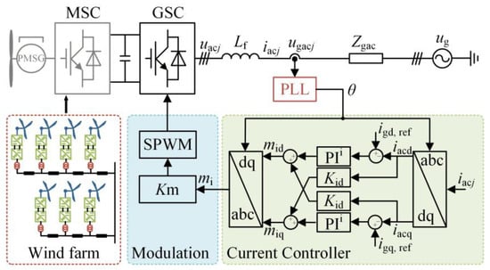
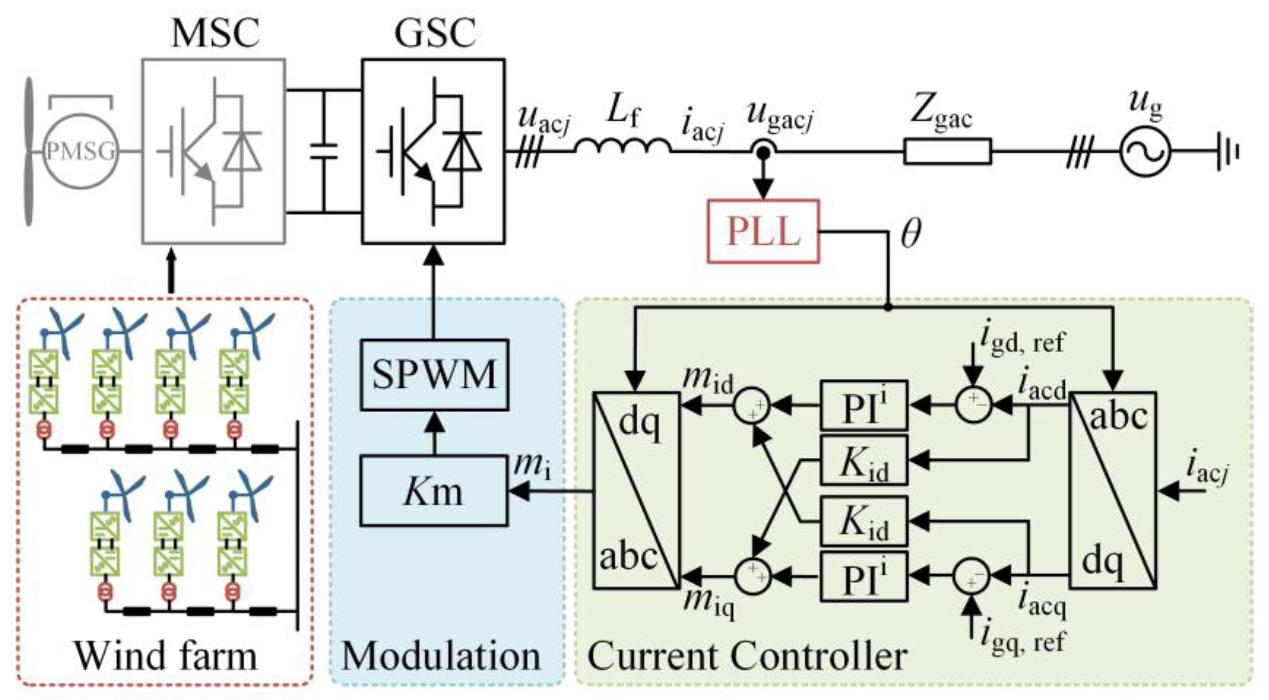
This study investigates a PMSG-based wind farm system composed of permanent magnet synchronous generators (PMSGs), a machine-side converter (MSC), and a grid-side converter (GSC). Identical PMSG units are aggregated into an equivalent generator, and with a sufficiently large DC-link capacitance, the combined PMSG–MSC subsystem can be approximated as a constant power source [29]. Figure 1 presents the simplified main circuit and controller of the system.
Figure 1.
Configuration of the PMSG-based wind farm system.
2.2. Small Signal Modeling of the PMSG-Based Wind Farm System with Different PLLs
Considering balanced three-phase steady-state operation, the GSC main circuit is simplified using a single-phase equivalent model. Based on harmonic state-space (HSS) theory, the frequency-domain small-signal model of the main circuit is derived as
where Δ denotes a small-signal perturbation component, and ΔS is the derivative coefficient matrix.
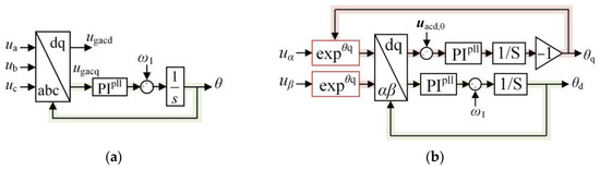
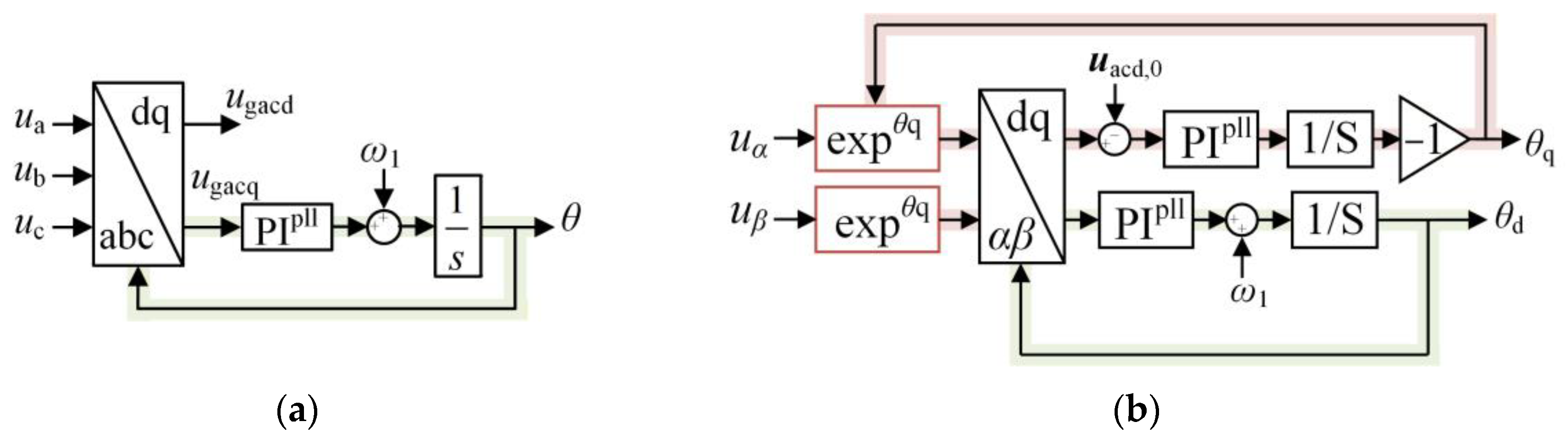
To synchronize with the AC voltage at PCC, the synchronous reference frame phase-locked loop (SRF-PLL) is employed, as illustrated in Figure 2a, where the system and converter dq reference frames are denoted by superscripts s and c. Additionally, the SPLL, proposed in [25], is shown in Figure 2b.
Figure 2.
Block diagram of SRF-PLL and SPLL: (a) Block diagram of SRF-PLL; (b) Block diagram of SRF-PLL.
2.2.1. Modeling of SRF-PLL
According to the SRF-PLL structure, the detected phase variation Δθd in the HSS model is
Based on the HSS model of the Park and inverse Park transformations (PT and IPT) in reference [30], the PT and IPT in the current loop are given by:
where Td+ and Tq+ represent the equivalent matrices for the PT, while Td− and Tq− are the equivalent matrices for the IPT. iacd,0 and iacq,0 are the d- and q-axis component matrices of the steady-state AC current. and are the steady-state matrices of the d- and q-axis components of the modulation signal.
2.2.2. Modeling of SPLL
The SPLL simultaneously track the grid d-and q-axis voltages of the grid and generates a combined dq-axis signal; the d- and q-axis phase variations can be obtained as follows:
where GPLL,d(s) and GPLL,q(s) are the d- and q-axis transfer functions. When the parameters of GPLL,d(s) and GPLL,q(s) are identical, TPLL,d(s) and TPLL,q(s) are also equal.
What is more, the output Δθdq of the SPLL has an effect on the PT and IPT of the current controller, which is expressed by:
2.2.3. Modeling of CC
According to the schematic of the current controller (CC), the perturbation components of the modulation signal, Δmid and Δmiq, are as follows:
where Gi represents the transfer function matrix of the current loop, and Kid is the decoupling coefficient matrix.
Combining the modeling of PLLs and CC with the relationship between the grid voltage and PCC voltage [31], yields:
where Hi and Hv represent the transfer relationship matrices from Δiac and Δugac to Δmi. Based on the frequency coupling relationship, the two-dimensional impedance is extracted from TGSC to obtain the converter AC impedance matrix ZGSC as follows:
where Zpp and Znn are the impedance at the perturbation frequency ωp and the coupling frequency ωp-2ω1, respectively. Zpn and Znp represent the cross-frequency coupling impedances.
3. Impedance Decoupling and Damping Degradation Induced by SPLL
3.1. Grid-GSC Impedance Decoupling Mechanism of the SPLL
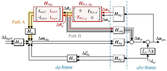
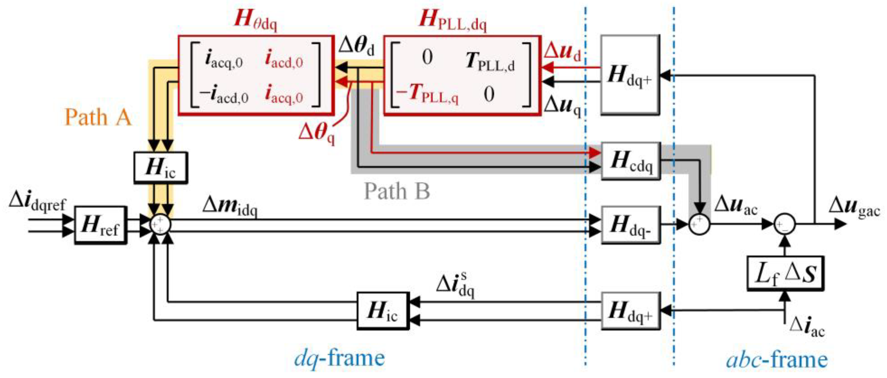
Figure 3 presents the block diagram of the GSC with SPLL in the dq-axis. Compared with the SRF-PLL, the SPLL mainly modifies the transfer-function representation, where the original SRF-PLL transfer relationship is replaced by the matrices HPLL,dq, Hθdq, and Hcdq.
Figure 3.
Block diagram of the GSC with SPLL in the dq-axis.
The Δud-established feedback loop introduced by the SPLL affects the system through two transmission paths, denoted as Path A and Path B. Path B originates from the parasitic PLL effect associated with the IPT inside the current controller and mainly reflects coordinate transformation dynamics; therefore, it is not further considered.
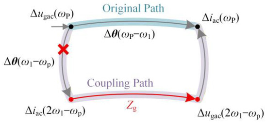
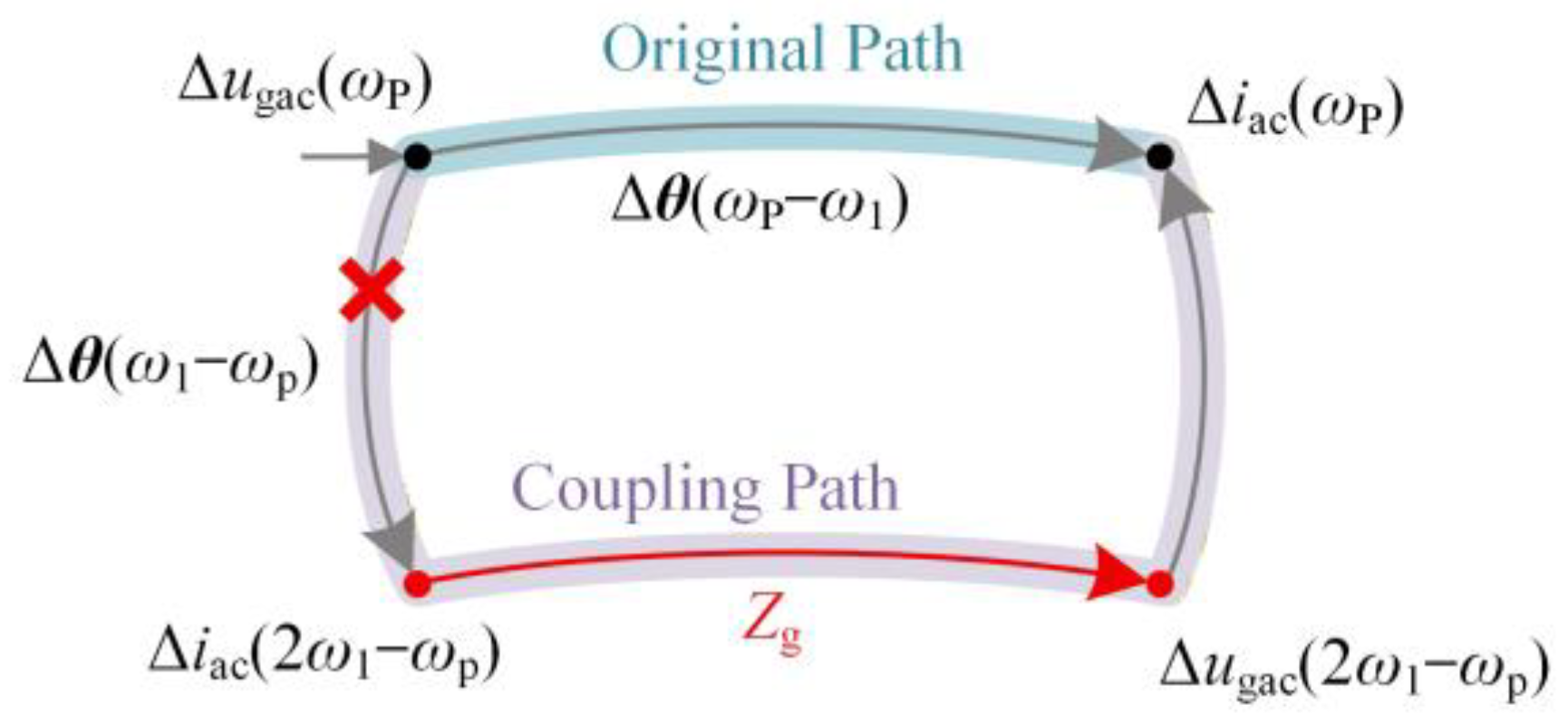
In contrast, Path A involves the matrices HPLL,dq and Hθdq, which exhibit identical diagonal elements and opposite off-diagonal elements. According to the transformation rule reported in [32], when transformed into the complex-vector domain, the second-harmonic component is eliminated, removing the PLL-induced frequency-coupling path. As a result, the impact of grid impedance Zg on the GSC impedance is suppressed, achieving effective grid–converter decoupling, as illustrated in the harmonic signal-flow graph in Figure 4.
Figure 4.
Harmonic signal-flow graph of the GSC.
3.2. Analysis of the Adverse Effect of SPLL on Damping
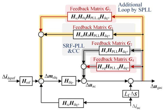
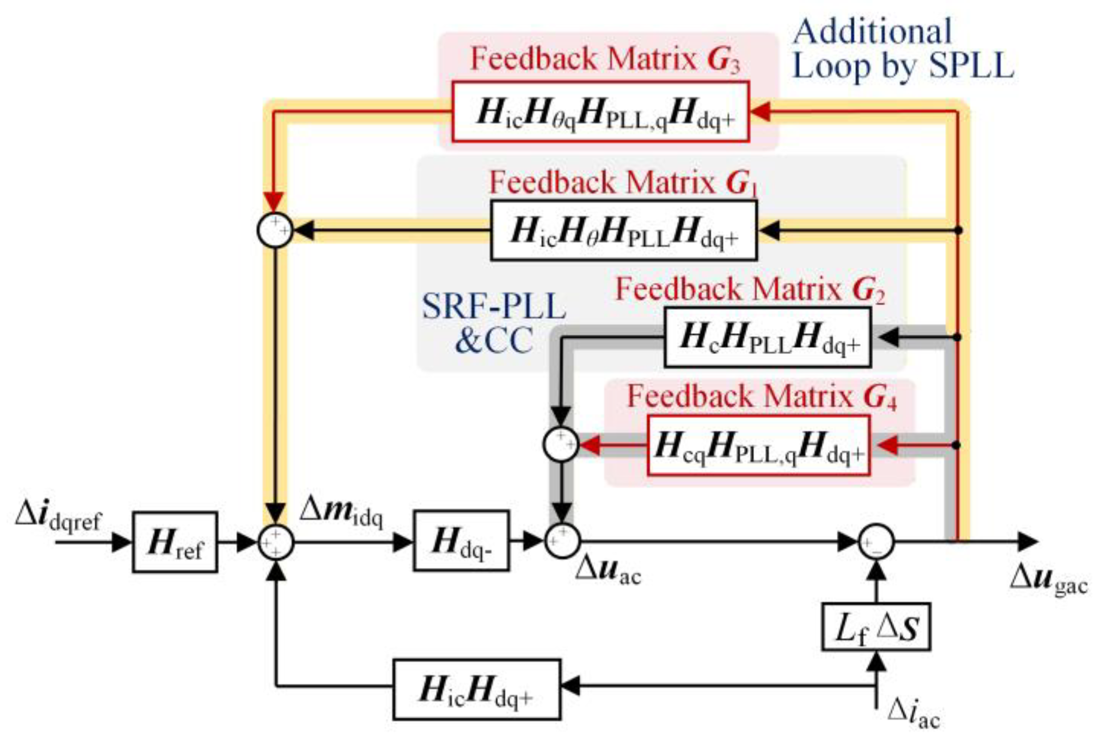
While eliminating the coupling path, the structural modification introduced by the SPLL simultaneously reconstructs the system feedback path of PCC voltage perturbation Δugac. Figure 5 compares the simplified feedback structures of the SRF-PLL and the SPLL. The feedback matrices G1 and G3 correspond to Path A in Figure 3, while G2 and G4 originate from Path B. For both PLL types, the PCC voltage participates in two feedback loops represented by G1 and G2. When the SPLL is adopted, two additional feedback paths emerge through the matrices G3 and G4. The feedback matrices for each path are given in (11)–(14).
Figure 5.
Comparison of the system block diagram with SRF-PLL and SPLL.
For G1 and G2, it has been demonstrated that these paths, introduced by the SRF-PLL, shape the impedance of GSC into a negative resistance in the q-axis, thereby posing a threat to system stability [33]. In Path 3, Δugac, after the PT within the PLL, is positively fed back to the modulation output of the CC, thereby influencing the system impedance characteristics. In Path 4, all elements of G4 are positive. As a result, even a small voltage disturbance at the PCC tends to be amplified along this path, thereby degrading GSC damping. Consequently, compared with the SRF-PLL case, the SPLL may further weaken system damping.
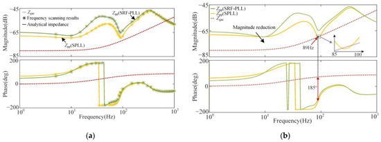
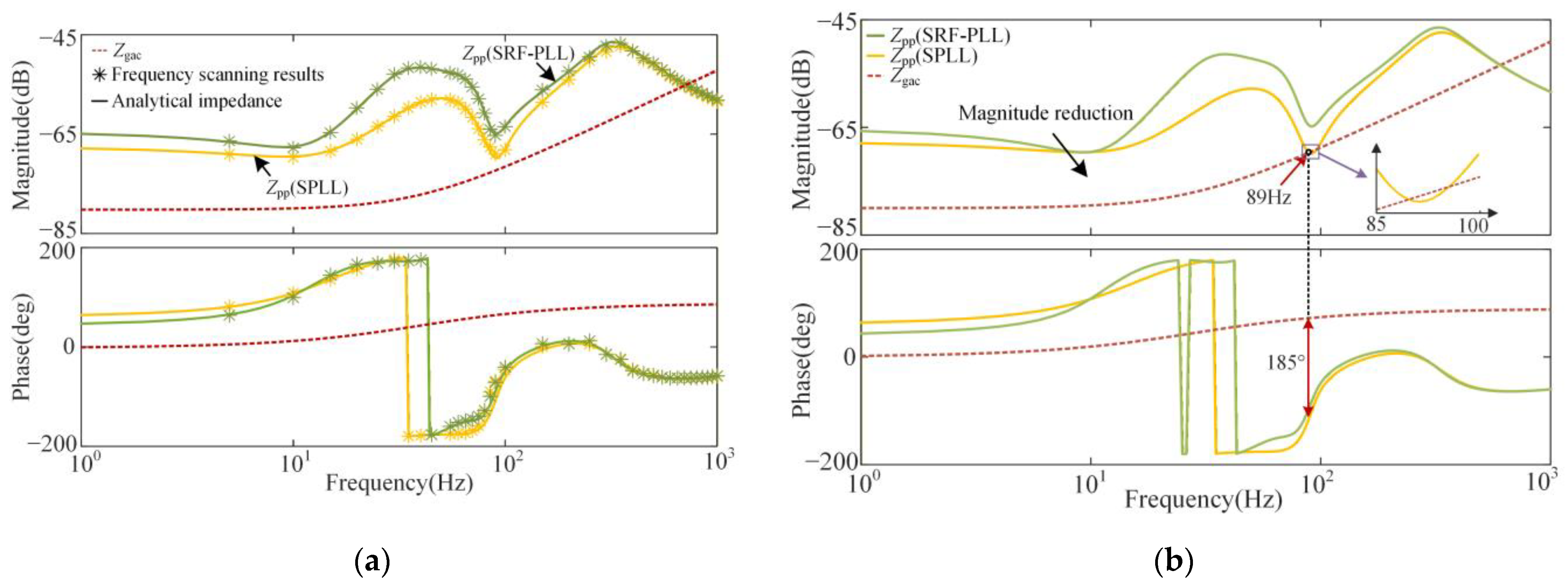
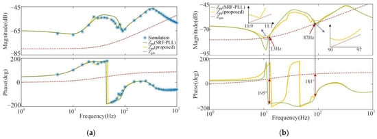
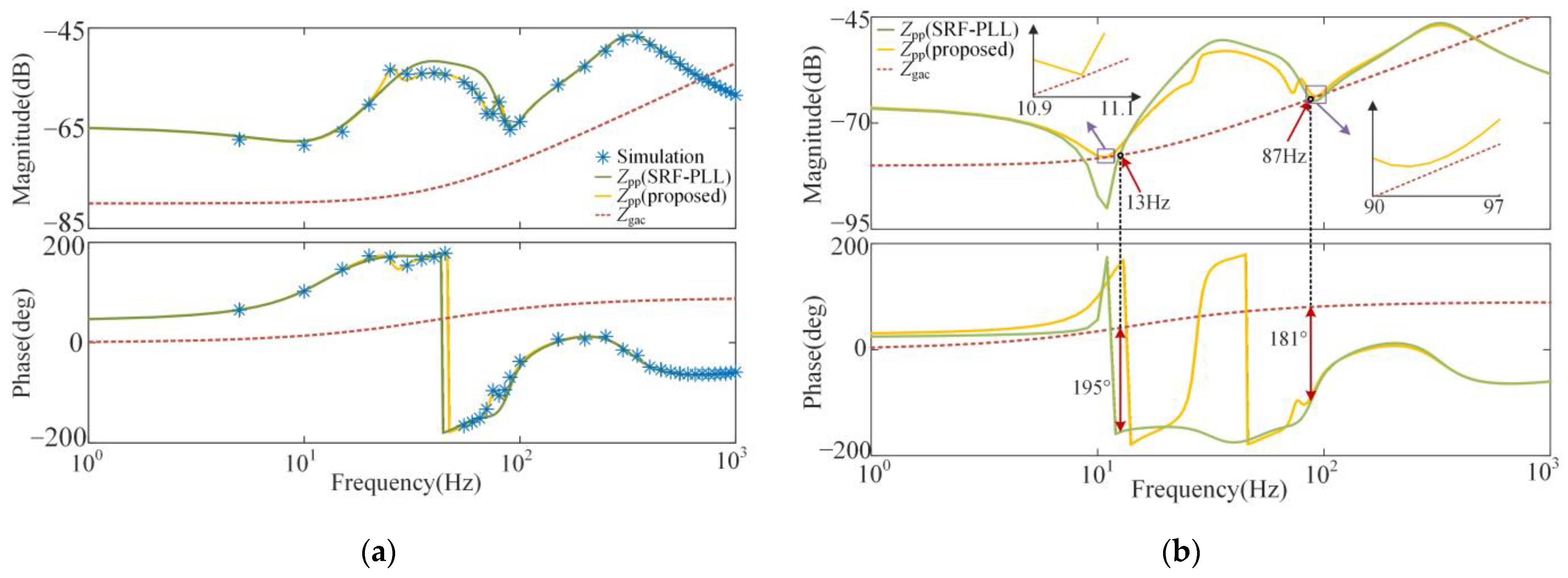
Figure 6 compares the impedance of the GSC using SRF-PLL and SPLL with Lg = 40 μH (SCR = 6.6) and 56 μH (SCR = 5.1). In Figure 6a, the analytical impedance of the GSC matches the simulated outcomes, thereby confirming the accuracy of the impedance model. In Figure 6b, as the grid stiffness decreases (Lg = 56 μH), the impedance of the SPLL-based GSC intersects with the grid impedance at 85 Hz, and the phase difference σPD exceeds 180°, thus satisfying the instability criterion. In contrast, the GSC employing the SRF-PLL maintains a phase difference below 180°, thus remaining stable. The results indicate that the reduction in low-frequency impedance magnitude increases the likelihood of impedance intersection and enlarges the capacitive negative-damping region, which is detrimental to system stability.
Figure 6.
The impedances of GSC with SPLL under different grid strengths: (a) Bode diagram of impedance models when Lg = 40 μH (SCR = 6.6); (b) Bode diagram of impedance models when Lg = 56 μH (SCR = 5.1).
The analysis reveals that the impedance decoupling capability of the SPLL and its adverse damping effect originate from the same structural modification. By eliminating the frequency-coupling path, the SPLL suppresses the influence of grid impedance on the converter dynamics. However, the SPLL simultaneously reduces GSC passivity, leading to a downward shift of the impedance magnitude and an expansion of the low-frequency negative-damping region. Consequently, although the grid-GSC interaction is weakened, the system becomes more susceptible to oscillations under weak-grid conditions.
4. A Partial Impedance Decoupling Method Based on the SPLL
4.1. Design for Partial Impedance Decoupling
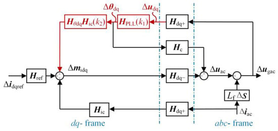
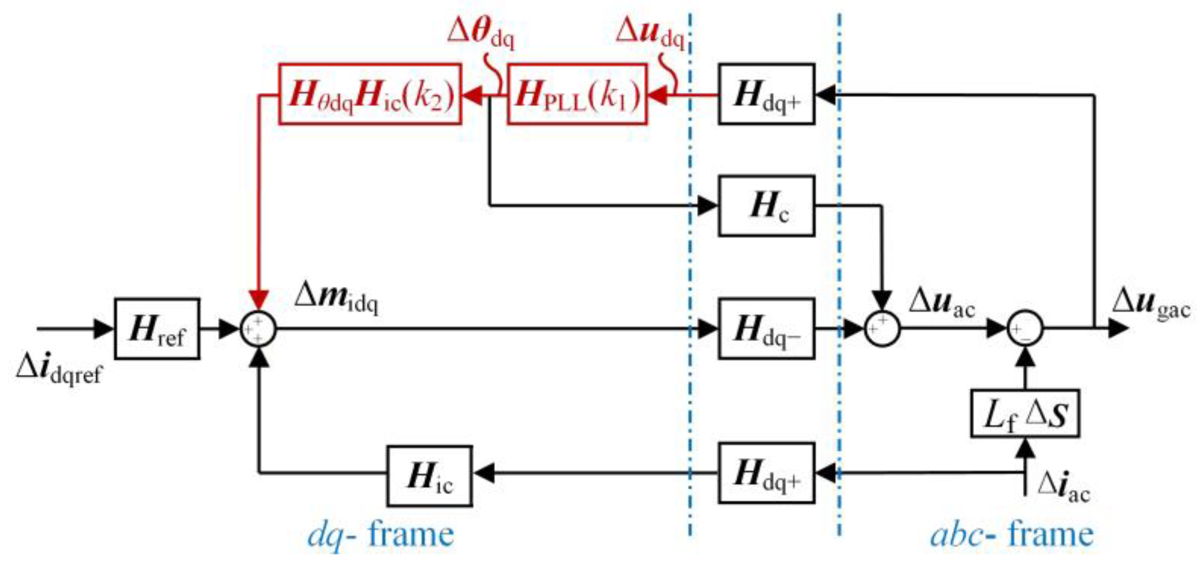
To reconcile the conflict between impedance decoupling and system damping in SPLL-based GSC, this paper proposes a partial impedance decoupling method. The central idea is to reshape the transmission paths by adjusting the coefficients and equivalent compensation, as shown in Figure 7. The implementation of the proposed approach is realized at two control layers: the PLL and the current controller.
Figure 7.
Block diagram of the proposed partial decoupling.
4.1.1. Implementation in the PLL
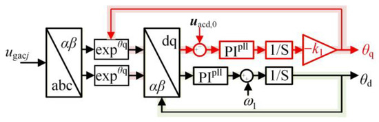
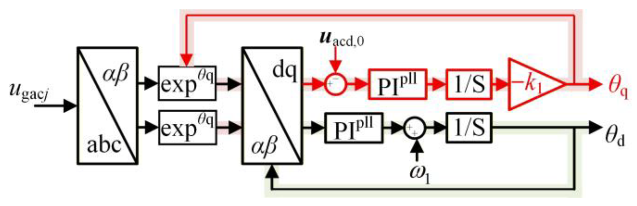
Considering that HPLL,dq(s) represents the transfer function matrix of the PLL, its off-diagonal elements serve as a key indicator of PLL symmetry. To achieve a balance between decoupling and damping performance, an adjustable coefficient k1 is introduced to regulate the off-diagonal element TPLL,q(s) of the matrix HPLL,dq(s).
Accordingly, the resulting improved SPLL configuration is illustrated in Figure 8. In this structure, the d-axis phase component remains consistent with that of the conventional SRF-PLL, whereas the q-axis phase component θq is reconstructed from the voltage signal ud.
Figure 8.
Depiction of the proposed partial decoupling in the PLL.
Consequently, the phase variation of the PLL Δθdq can be reformulated into a modified matrix form incorporating the adjustable coefficient k1:
Therefore, when k1 = 0, TPLL,q (k1) = 0, and the PLL becomes equivalent to the SRF-PLL. When k1 = 1, TPLL,q (k1) = TPLL,d, corresponding to the SPLL structure.
4.1.2. Implementation in the Current Controller
The q-axis phase output of the SPLL Δθq further propagates into the current control loop through the PT and the current regulation process. According to the signal propagation paths shown in Figure 7, Δθq is transferred through the matrices Hθdq(s) and H ic(s), thereby influencing the modulation signal Δmidq generated by the current controller.
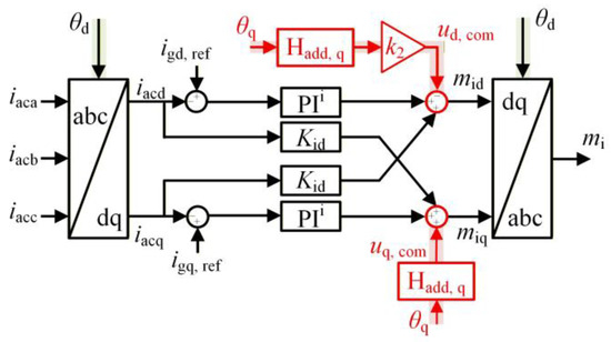
To further balance symmetry and damping performance in the current controller, an adjustment coefficient k2 is introduced to regulate the participation degree of θq within the current controller. Accordingly, a phase-angle compensation path is established from θq to the current controller, scaled by the coefficient k2, as illustrated in Figure 9.
Figure 9.
Depiction of the proposed Partial Decoupling in the current controller.
Under unity power factor operation, the steady-state q-axis current satisfies iacq,0 ≈ 0. This assumption allows the compensation terms associated with phase perturbations to be simplified in the small-signal model. By combining the expressions of Hθdq and Hic, the equivalent compensation effect introduced by the coefficient k2 can be derived as follows:
where Hadd,d and Hadd,q are the d- and q-axis compensation matrices, and Hfilter is the low-pass filter introduced to suppress the impact of high-frequency harmonics in the d-axis voltage [34], expressed at a single frequency as follows:
where ω0 represents the cutoff frequency, and ζ is the damping ratio.
Meanwhile, the perturbation components of the modulation signal Δmid and Δmiq are as follows:
Then the impedance of GSC with the proposed control method can be obtained, as in (10).
4.2. Parameter Design Procedure
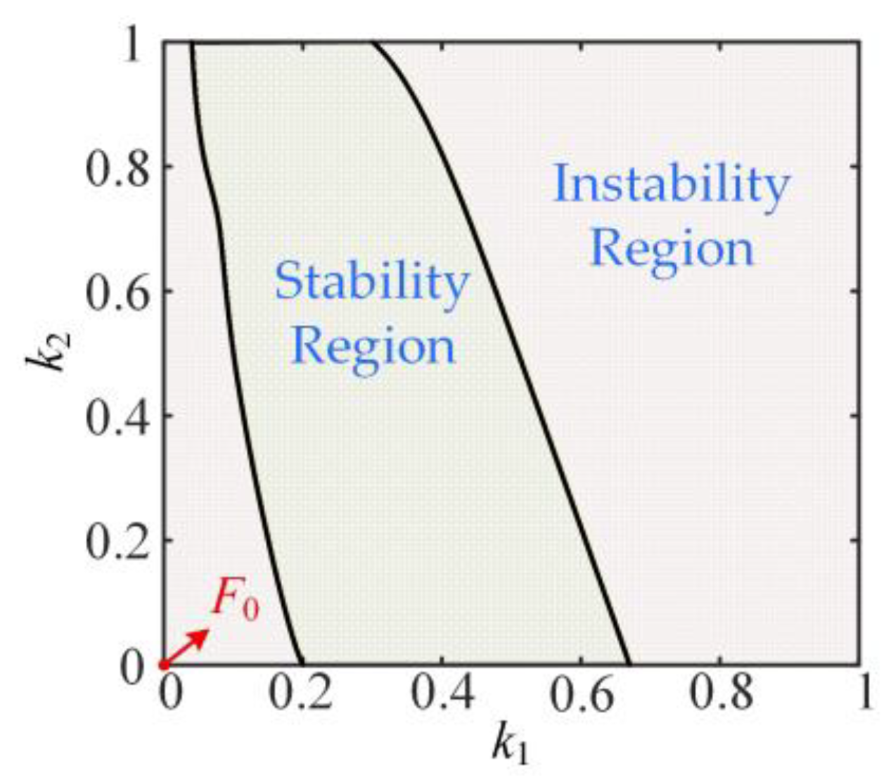
After introducing the compensation terms and adjustment coefficients, the system stability margin varies with different parameter settings. Since (k1, k2) = (0,0) corresponds to the non-decoupled case, whereas (k1, k2) = (1,1) represents the fully decoupled condition, the design domains of both parameters are confined to the closed interval [0, 1].
To ensure that the system stability meets the initial design criteria, either the adjustment coefficients must satisfy the condition that the impedance phase differences at intersection frequencies remain less than 180°.
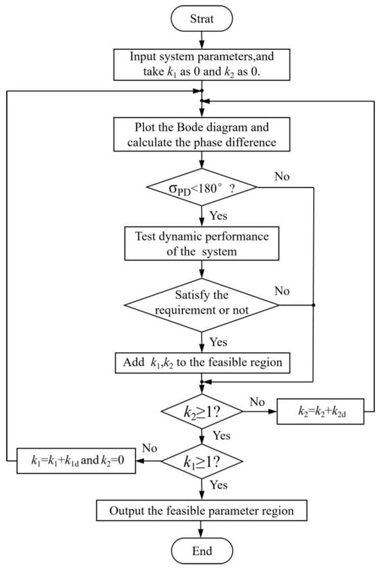
In addition to satisfying the constraint of the small-signal stability, the steady-state and dynamic performance must also be considered to ensure adequate system robustness. Specifically, the overshoot is limited to within 20% of the reference variation, and the settling time is required to be less than 0.5 s to guarantee satisfactory dynamic regulation capability. Based on these criteria, the parameter design procedure is shown in Figure 10. In this process, k1d and k2d represent the adjustment steps for the two adjustment coefficients, with a recommended value of 0.01. Finally, the algorithm yields the admissible parameter region that simultaneously satisfies the stability and dynamic performance constraints, from which the selectable ranges of k1 and k2 can be determined.
Figure 10.
Parameter design procedure of adjustment coefficients.
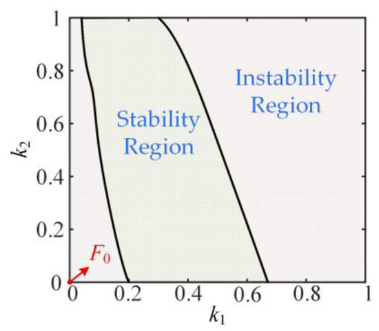
Taking the system parameters listed in Appendix A.1 with Lg = 110 μH as an example, Figure 11 illustrates the stable operating region of the system. The stable and unstable regions are indicated in green and red, respectively. Point F0 denotes the operating condition without the proposed strategy, under which oscillatory behavior occurs. After implementing the proposed method, appropriate parameter selection enables the fulfillment of the initial design objective, namely, the enhancement of system stability.
Figure 11.
The system stability region under different parameter settings.
4.3. Stability Analysis and Model Verification of the Proposed Approach
Figure 12a shows the converter impedance characteristics before and after the control strategy is applied, with the Lg set to 40μH (SCR = 6.6). The green solid line denotes the analytical impedance of GSC with SRF-PLL, while the yellow solid line represents the equivalent impedance obtained using the proposed approach. The blue dots correspond to simulated results, validating the accuracy of the HSS model. The results show that the high-frequency impedance remains nearly unchanged, whereas slight variations appear within the 10–100 Hz range, mainly governed by the adjustment coefficient k1. Meanwhile, the capacitive negative-damping frequency band of the GSC impedance slightly decreases in this frequency range, which is beneficial for system stability.
Figure 12.
The impedances of GSC with the proposed control strategy under different grid strengths: (a) Bode diagram of impedance models when Lg = 40 μH (SCR = 6.58); (b) Bode diagram of impedance models when Lg = 110 μH (SCR = 2.8).
Furthermore, Figure 12b illustrates the Bode characteristics when the Lg increases to 110 μH. To achieve satisfactory dynamic performance, the adjustment coefficients are selected as k1 = 0.35 and k2 = 0.4. For the SRF-PLL case, the impedance satisfies the Nyquist instability criterion. However, the impedance of the GSC with the proposed strategy and the grid intersect at 458 Hz; the corresponding phase difference is 144.4°, indicating that the system will remain stable. This demonstrates that, by applying the proposed approach, the system can maintain stable operation in weaker grid conditions, thereby improving system stability efficiently.
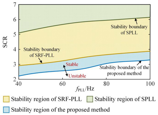
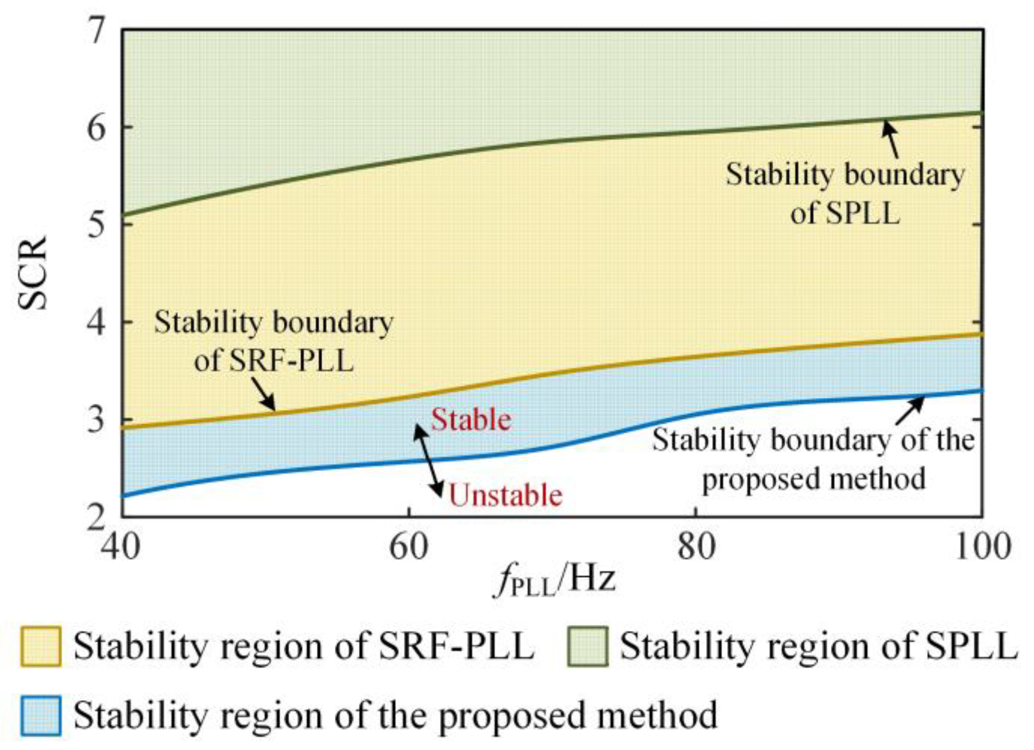
Based on the above conclusions, a further analysis is conducted by varying the PLL bandwidth fPLL and the SCR. The stability boundaries of the grid-connected system under weak-grid conditions can therefore be obtained for different control strategies, as illustrated in Figure 13. It can be observed that, within the same variation ranges of fPLL and SCR, the stability region of the system employing the SPLL is significantly smaller than that of the system adopting the SRF-PLL. After applying the method proposed in this paper, the system stability is markedly improved, thereby expanding its applicability under weak-grid conditions. The system is able to maintain stable operation even when the grid strength decreases by 10% in terms of SCR.
Figure 13.
System stability regions under different control strategies.
4.4. Comparison with the Established Method
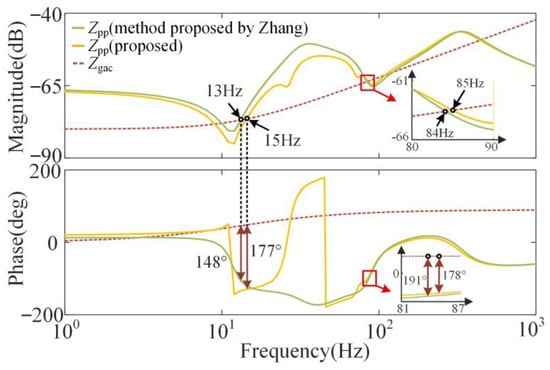
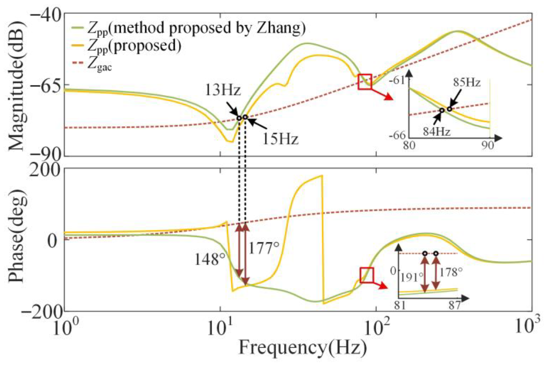
To further verify the advantages of the proposed method, a comparative study is carried out based on the system parameters listed in Appendix A.1, where the proposed approach is compared with the method presented in [15]. After applying the two methods, the impedance model of the GCC is shown in Figure 14. The impedance analysis indicates that when the grid impedance reaches 123μH (SCR = 2.5), the converter impedance obtained using the method in [15] intersects with the grid impedance at 84 Hz, and the corresponding phase difference exceeds 180°, implying instability. In contrast, the phase difference of the proposed method still satisfies the Nyquist stability criterion, thereby maintaining system stability and demonstrating the superiority of the proposed strategy.
Figure 14.
Comparison of the impedances of GSC with different methods.
5. Simulation and Experimental Verification
5.1. Simulation Verification
5.1.1. Experiment of the GSC System with Different PLLs
To validate the effectiveness of the proposed oscillation suppression strategy, a simulation model based on MATLAB R2023a/Simulink was developed for experimentation. The system parameters are listed in Appendix A.1.
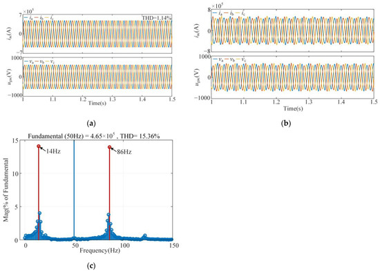
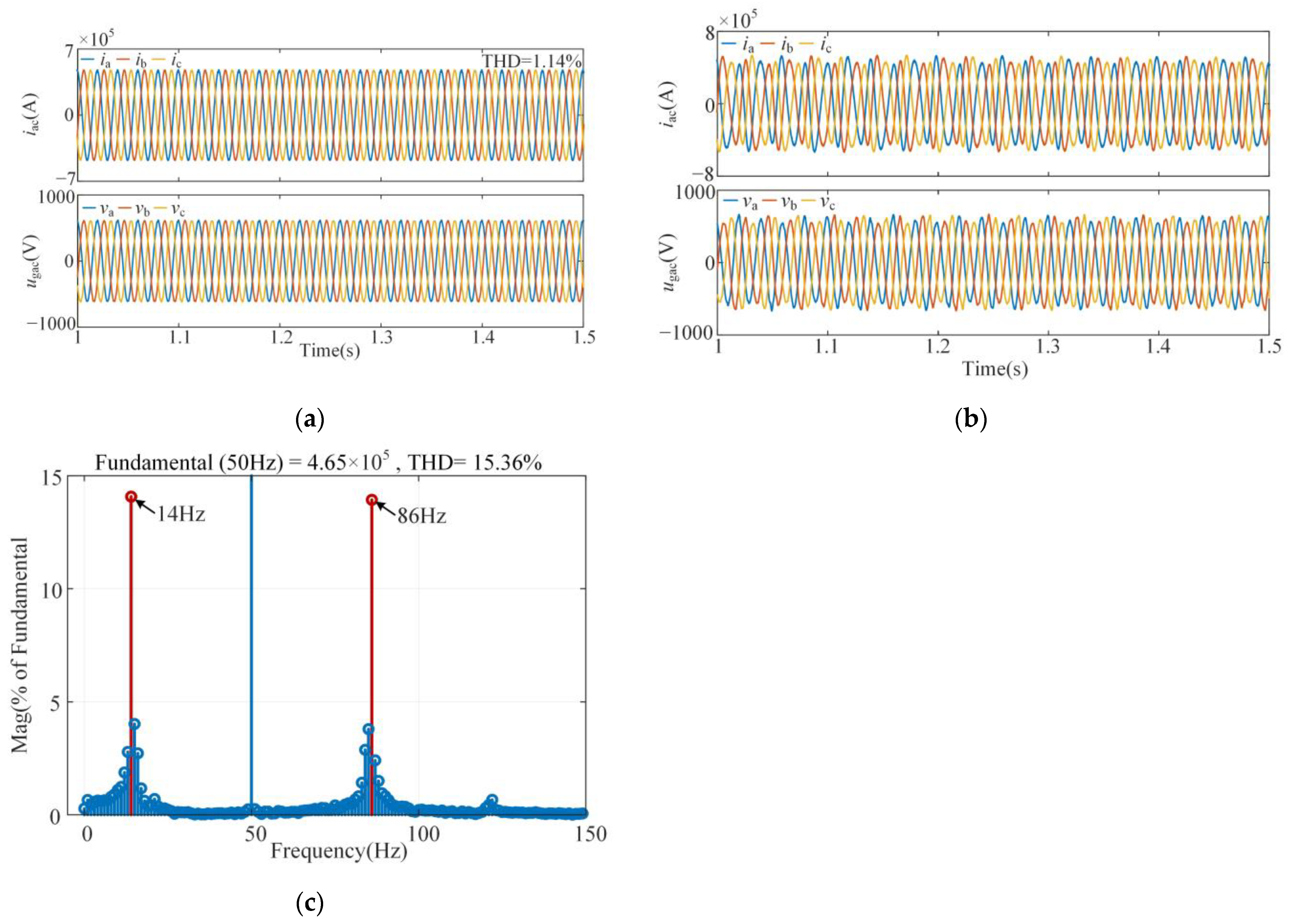
Figure 15 shows the experimental waveforms of a GSC adopting the traditional SRF-PLL under different grid impedance conditions. When Lg is 56 μH, the system operates stably with minimal harmonics in the PCC voltage and current, and the total harmonic distortion (THD) of the grid current is 1.14%. However, when Lg increases to 110 μH, harmonic oscillations occur in the grid-connected converter, leading to system instability. The current harmonic spectrum in Figure 15c reveals that the THD of the grid current is 15.36%, and two oscillation frequencies exist in the system: 14 Hz and 86 Hz, which are the coupling frequencies. These findings align with the analysis presented in Figure 12b.
Figure 15.
Waveforms and harmonic spectra of the GSC with SRF-PLL: (a) Waveforms when Lg = 56 μH (SCR = 5.1); (b) Waveforms when Lg = 110 μH (SCR = 2.8); (c) Harmonic spectra when Lg = 110 μH.
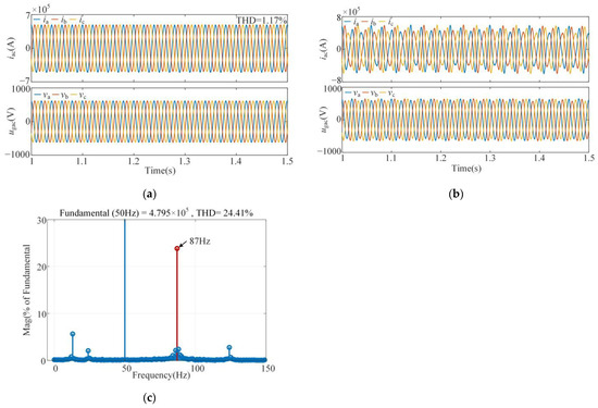
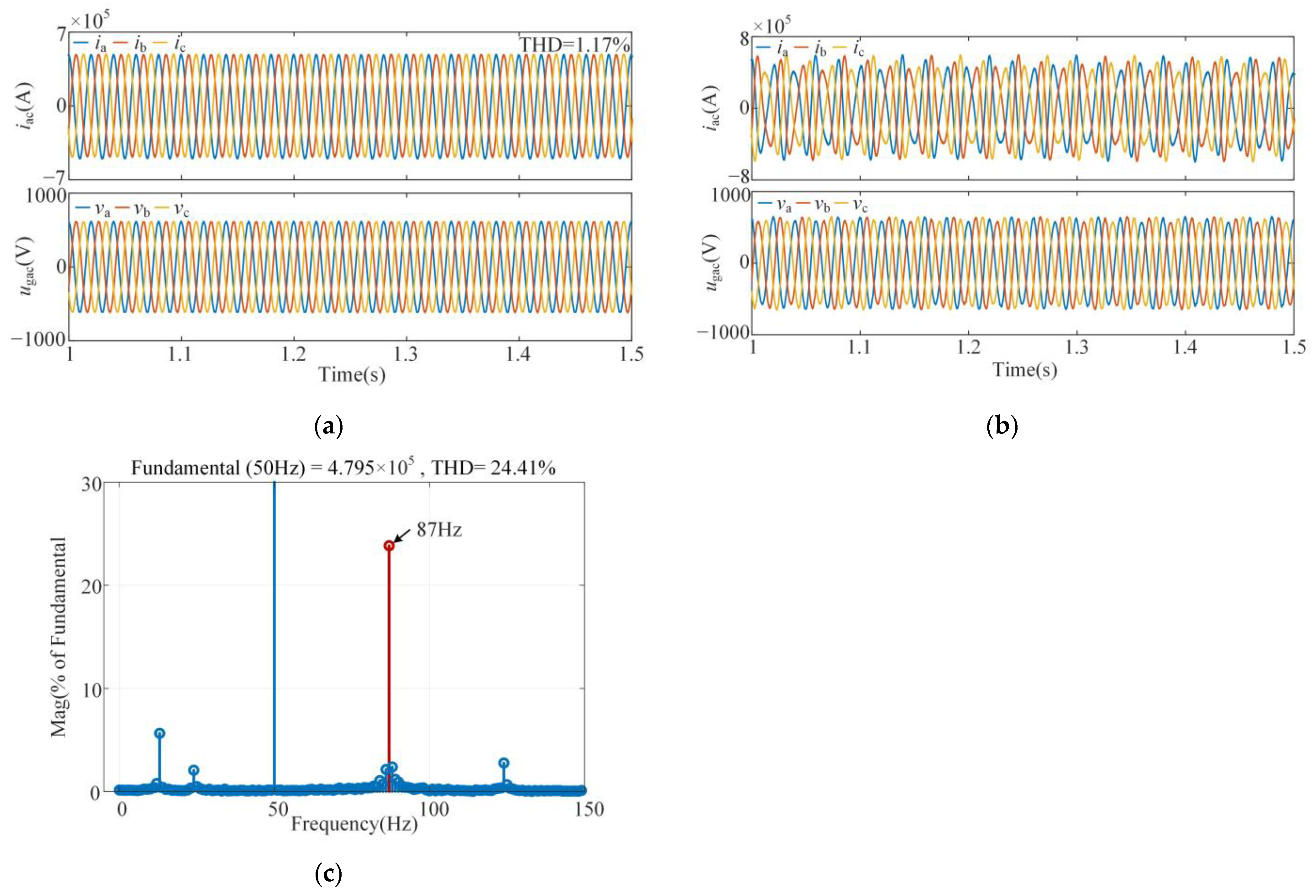
The experimental waveforms of the GSC adopting the SPLL under different grid impedances are given in Figure 16. It is obvious that when Lg is 40 μH, the system operates stably, with the grid current THD measured at 1.17%. However, when Lg increases to 56 μH, both the AC current and PCC voltage waveforms show considerable distortion, with harmonic resonances emerging in the system. In comparison to the SRF-PLL, the SPLL negatively impacts system stability. The THD analysis of the grid current reveals a value of 24.41%, with the dominant harmonic at 87 Hz, while the coupled 13 Hz component remains minimal, demonstrating effective suppression of the frequency coupling.
Figure 16.
Waveforms and harmonic spectra of the GSC with SPLL: (a) Waveforms when Lg = 40 μH (SCR = 6.6); (b) Waveforms when Lg = 56 μH (SCR = 5.1); (c) Harmonic spectra when Lg = 56 μH.
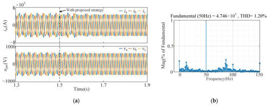
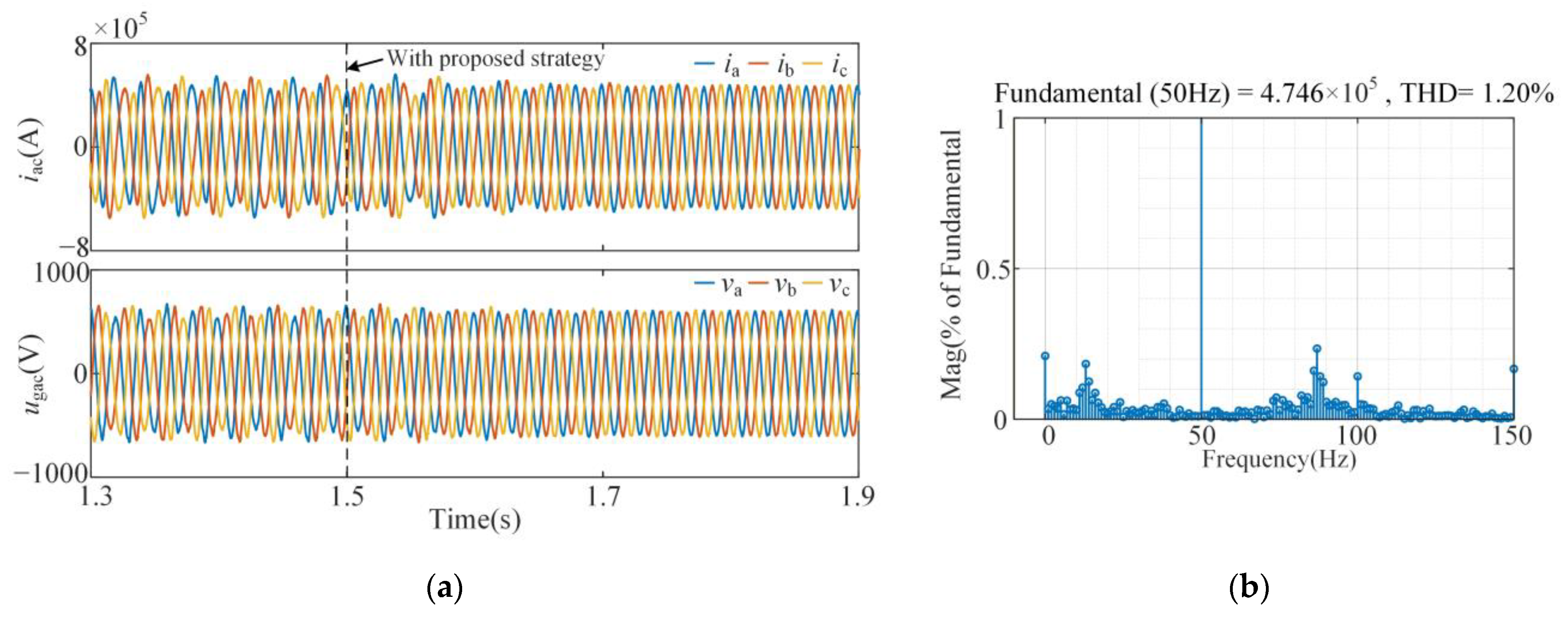
After implementing the proposed partial impedance decoupling control strategy, the GSC is capable of operating under more challenging grid impedance conditions. Figure 17 presents the grid current and voltage waveforms when Lg = 110 μH (SCR = 2.8), before and after applying the proposed method. The adjustment coefficients were switched from 0 to k1 = 0.35 and k2 = 0.4 at t = 1.5 s. As seen in the experimental waveforms, after applying the proposed control, the system transitions from instability to stable operation, with the THD of the current reduced to 1.2%, thus validating the effectiveness of the proposed stability enhancement strategy.
Figure 17.
Waveforms and harmonic spectra of the GSC utilizing the proposed strategy: (a) Waveforms before and after applying the proposed method; (b) Harmonic spectra after applying.
Under different grid impedance conditions, the system stability of the converter employing the SRF-PLL, SPLL, and the proposed method is analyzed. The impedance phase difference of the system under various operating scenarios is calculated, and the corresponding results are summarized in Table 1.
Table 1.
System Operating Conditions under Different Control Strategies.
5.1.2. Simulation Comparison with the Established Method
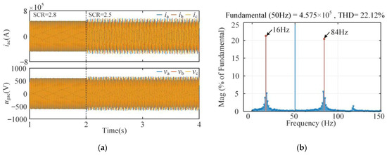
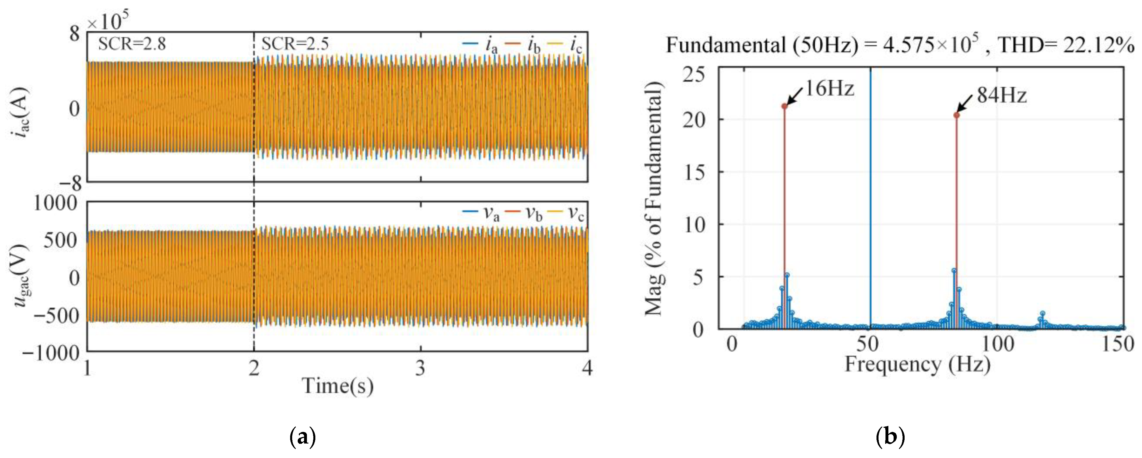
To further validate the superiority of the proposed method, a comparison is conducted with the approach presented in [15]. The simulation results of the existing method are illustrated in Figure 18. When the grid impedance increases from 110 μH to 123 μH, corresponding to a reduction of the SCR from 2.8 to 2.5, the strategy is no longer able to maintain stable system operation. Both the three-phase current and voltage transition from stable waveforms to severely distorted conditions. Meanwhile, the THD analysis reveals an oscillation at 84 Hz, which is consistent with the impedance analysis results.
Figure 18.
Waveforms and harmonic spectra of the GSC with the established method: (a) Waveforms when Lg changes from 110 μH (SCR = 2.8) to 123 μH (SCR = 2.5); (b) Harmonic spectra when Lg = 123 μH.
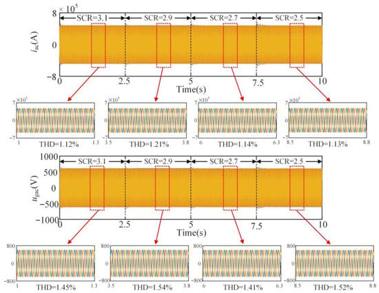
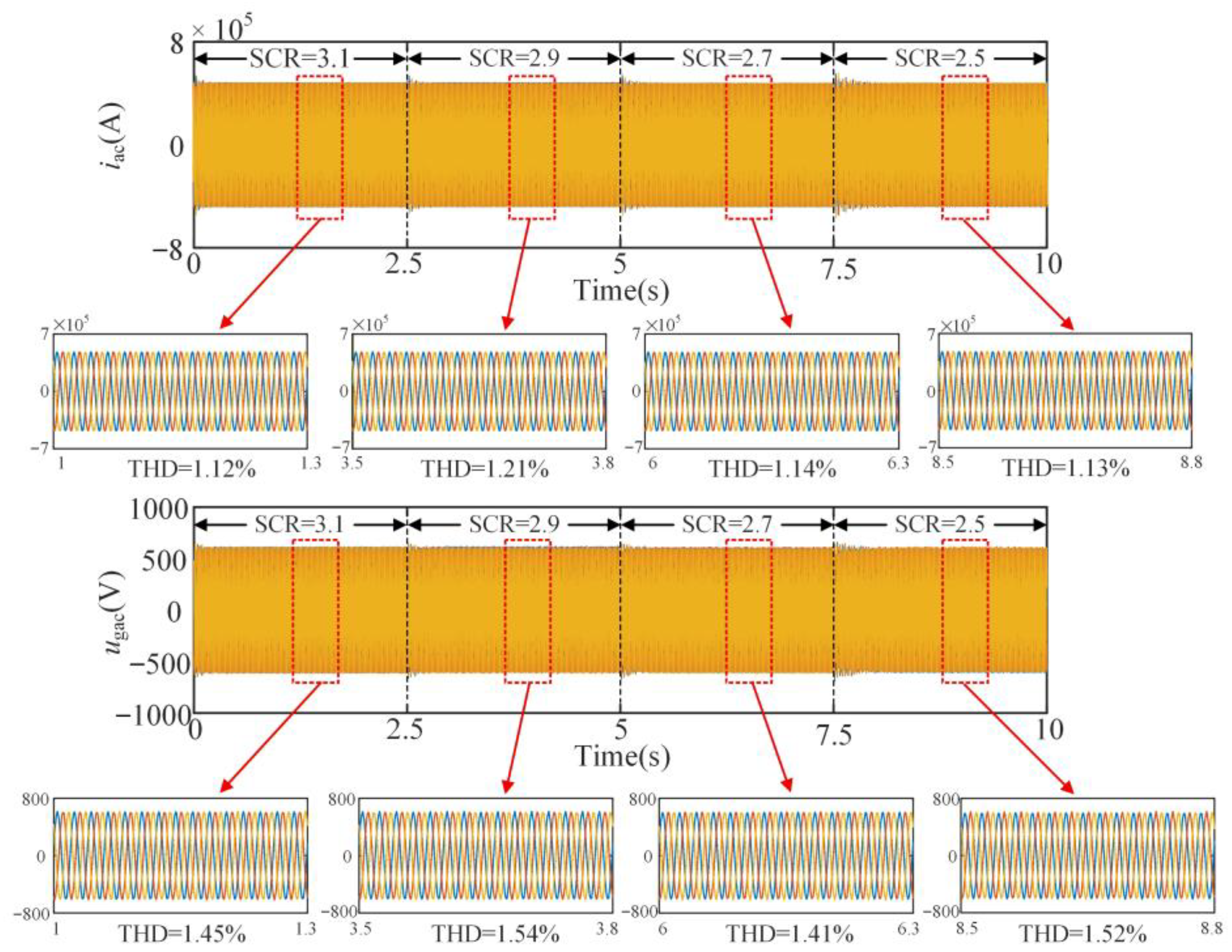
In contrast, the proposed strategy enables the system to maintain stable operation under varying grid conditions. At t = 2.5 s, 5 s and 7.5 s, the SCR is successively changed from 3.1 to 2.9, 2.7, and 2.5, respectively. The voltage and current waveforms at the PCC, together with the corresponding harmonic contents, are shown in Figure 19. The results demonstrate that the system remains stable under different grid strengths, while the dynamic performance satisfies the fundamental requirements for engineering applications. The comparative simulation results further confirm that the proposed method exhibits stronger adaptability to more severe grid conditions.
Figure 19.
Waveforms of the GSC utilizing the proposed method under different SCRs.
5.1.3. Performance Analysis of the Proposed Methods
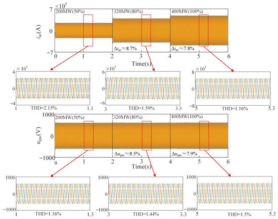
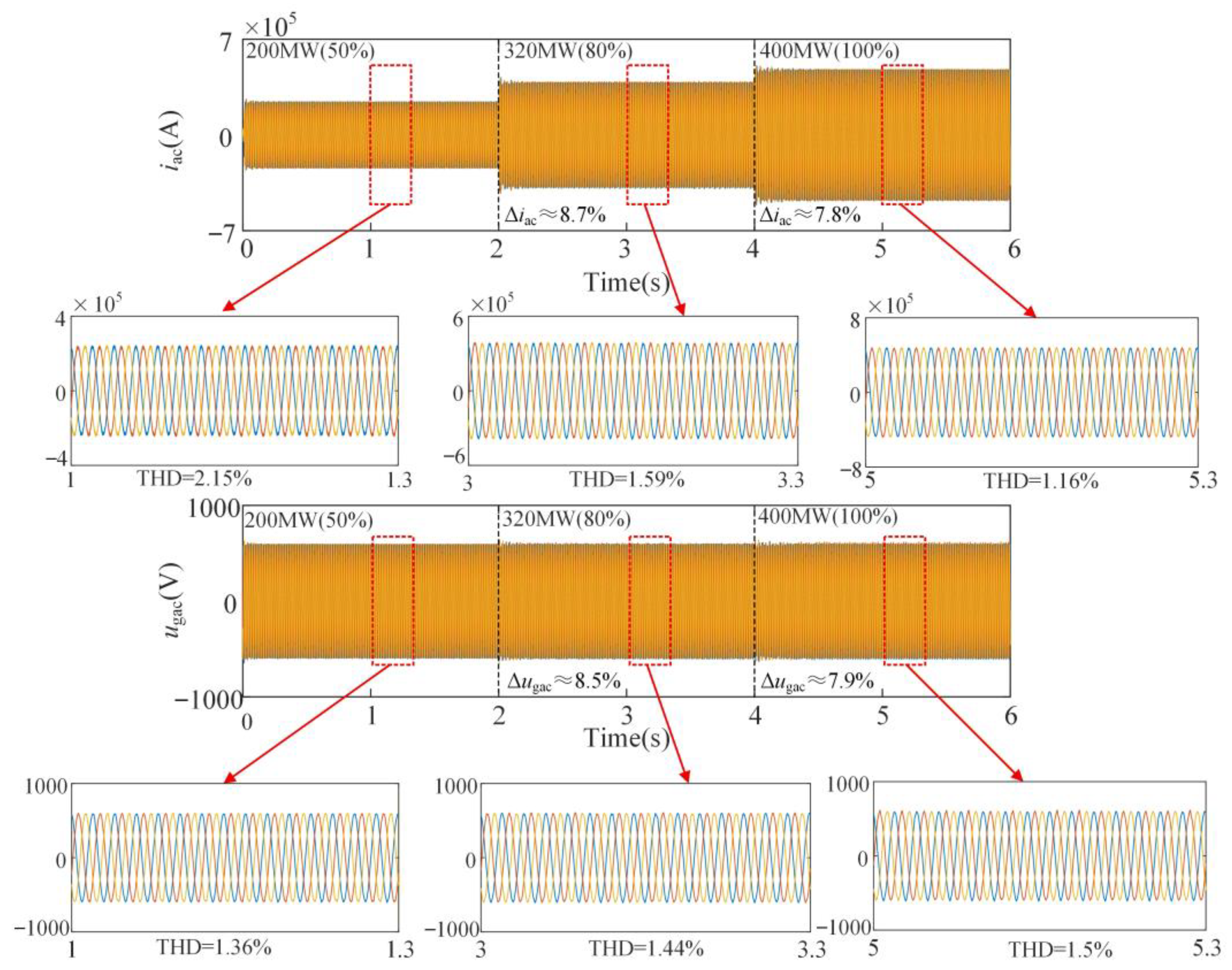
To further validate the control performance of the proposed improved SPLL control strategy under weak-grid conditions, Figure 20 presents the dynamic experimental waveforms when Lg = 123 μH (SCR = 2.5). As shown, the power of the PMSG-based wind farm system gradually increases from 200 MW to 400 MW. The active power output is successfully regulated within 0.3 s, while the maximum variations in current and voltage remain within 20% of their reference values, indicating that the system achieves both excellent steady-state and dynamic performance.
Figure 20.
Waveforms of the GSC with the proposed control method under different power levels.
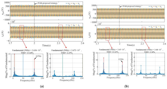
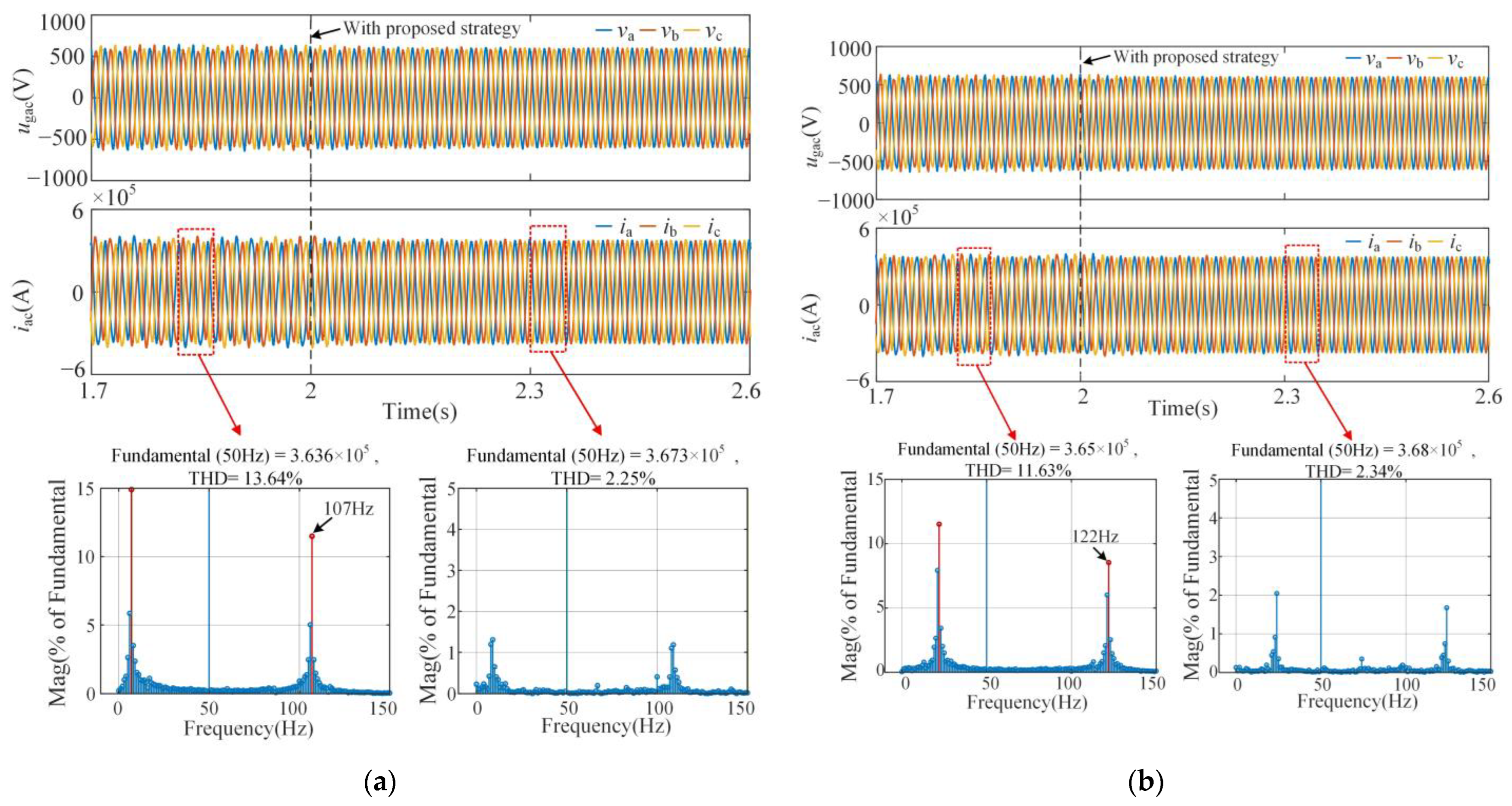
In addition, simulations under different operating cases presented in Appendix A.2 have been conducted to further verify the general applicability of the proposed method, as shown in Figure 21. As observed in the results, oscillatory behaviors appear in both the voltage and current waveforms before the proposed method is applied. After activating the proposed control strategy, the system operates stably. These results demonstrate the general effectiveness and applicability of the proposed method.
Figure 21.
Waveforms and harmonic spectra of the GSC under different operating cases: (a) Waveforms under case 1; (b) Waveforms under case 2.
5.2. Experimental Verification
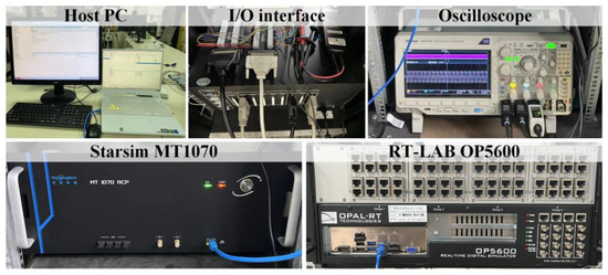
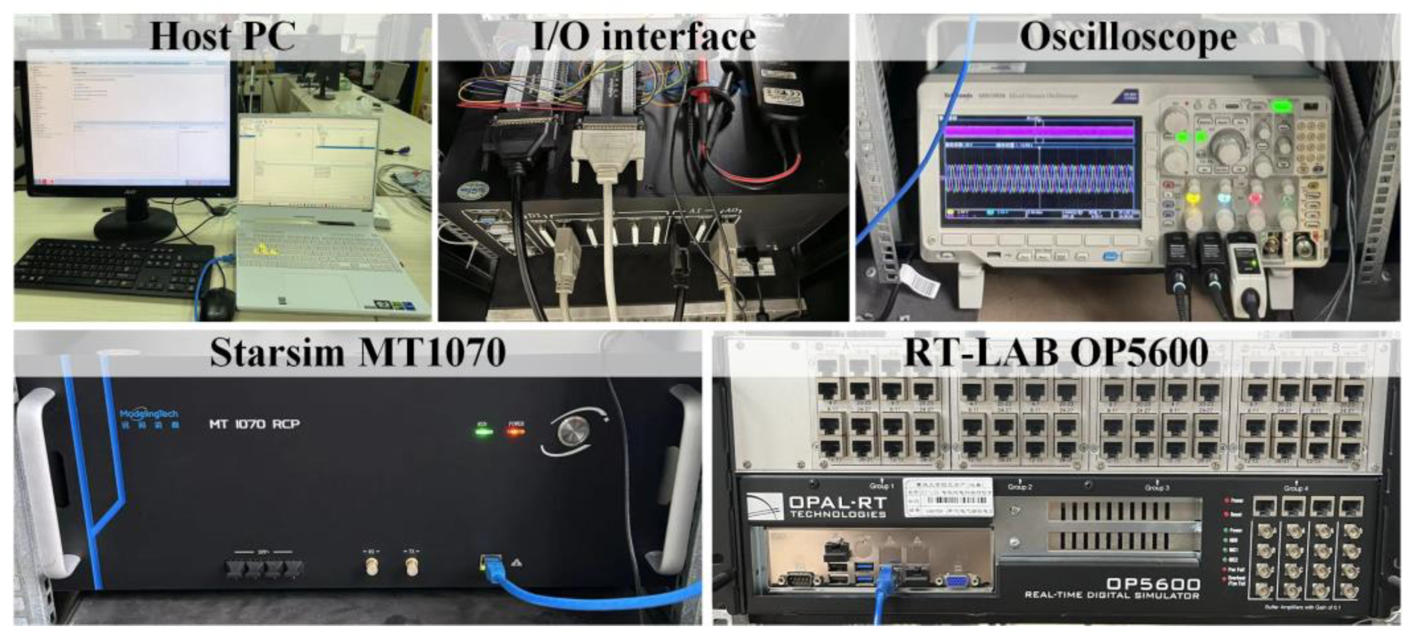
A series of hardware-in-the-loop experiments was conducted on an experimental platform to validate the proposed strategy. The main circuit was simulated using RT-LAB OP5600 (OPAL-RT TECHNOLOGIES, Montreal, QC, Canada), while the control signal was generated by the Starsim MT1070 (Modeling Tech, Shanghai, China) with a control step size of 50 µs. The system parameters are identical to those in Appendix A.1, and the experimental setup is illustrated in Figure 22.
Figure 22.
Experimental setup.
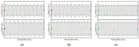
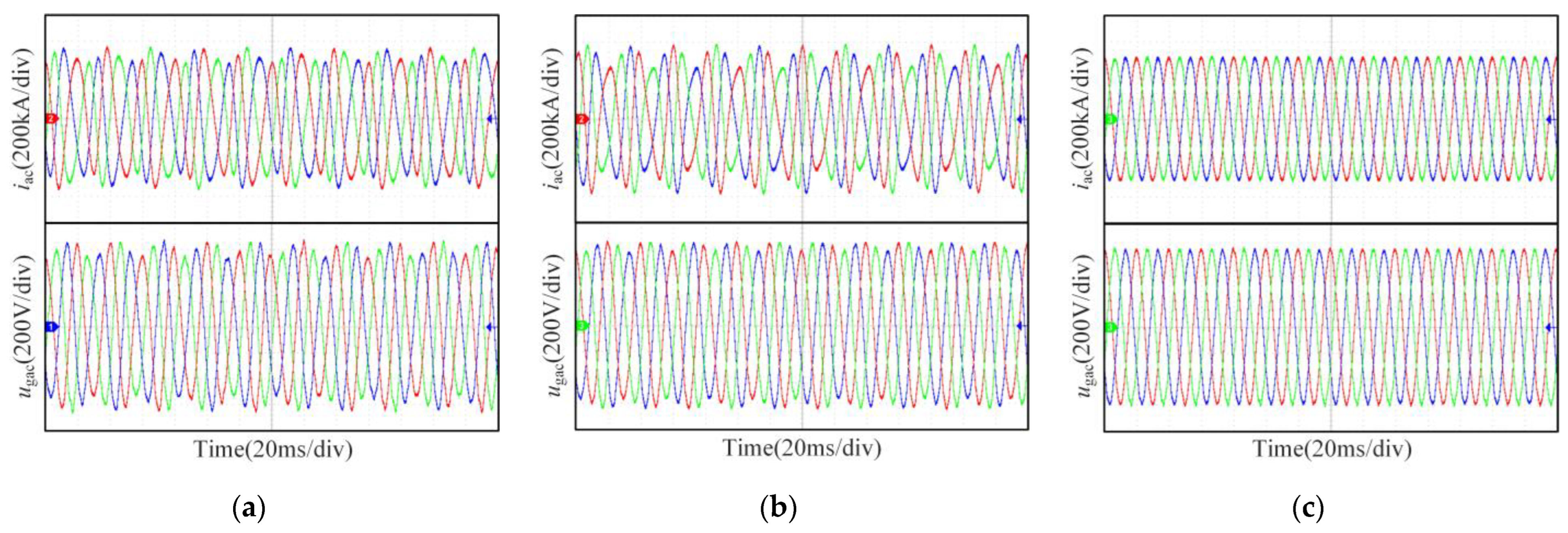
Figure 23 displays the experimental waveforms of the GSC utilizing different PLL structures. The PLL is first tested for comparison, as illustrated in Figure 23a. As seen, the system exhibits instability when Lg = 110 μH (SCR = 2.8). The grid voltage is maintained as a purely sinusoidal signal, indicating that oscillations in the system are caused by stability issues. However, when Lg = 56 μH (SCR = 5.1), although the grid condition improves, oscillations can be observed in both the three-phase grid currents igabc and voltages vgabc, which confirms that the SPLL introduces a passive impact on system stability. Figure 23c presents the experimental results of the GSC adopting the proposed control for stability enhancement under weak grid conditions, from which it is evident that the system remains stable with Lg = 110 μH (SCR = 2.8). Therefore, the proposed control strategy efficiently suppresses oscillations and improves overall system stability.
Figure 23.
Experimental waveforms of the GSC with different PLLs: (a) The GSC using the SRF-PLL; (b) The GSC using the SPLL; (c) The GSC using the proposed control.
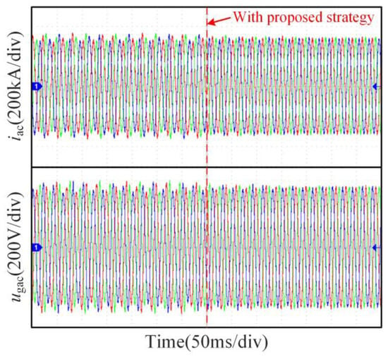
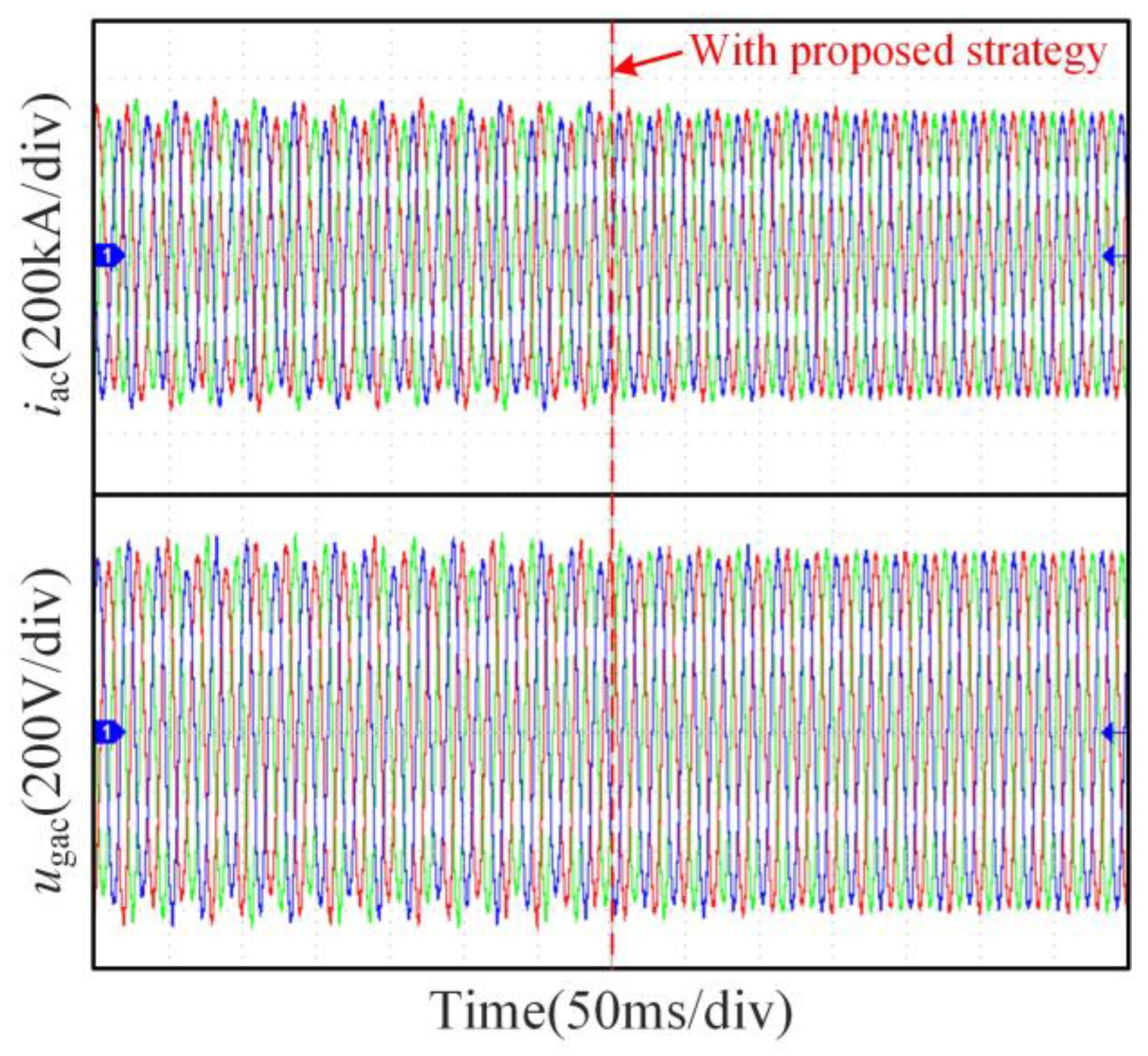
Figure 24 presents the experimental waveform observed during the transition from the conventional SRF-PLL control method to the proposed scheme. As observed, prior to the implementation of the new control strategy, the system exhibits noticeable instability. However, it is successfully stabilized after implementing the proposed strategy. This improvement in performance serves as strong evidence for the effectiveness of the enhanced SPLL control strategy.
Figure 24.
Experimental waveforms of the GSC, which changes its control strategy.
6. Conclusions
This paper reveals the intrinsic decoupling mechanism of the SPLL and clarifies its associated influence on system stability. Subsequently, a partial impedance decoupling control method based on the SPLL is proposed, incorporating equivalent d- and q-axis compensation terms, together with adjustment coefficients, to achieve a tradeoff between grid-GSC coupling and system damping. Theoretical analysis demonstrates that the proposed strategy maintains stable operation as grid strength decreases. Experimental results further confirm satisfactory steady-state and dynamic performance, validating the effectiveness of the improved approach. Future work will investigate the applicability and feasibility of the SPLL in multi-wind-turbine grid-connected systems and more complex renewable energy integration scenarios.
Author Contributions
Conceptualization, Z.L. and L.X.; methodology, Z.L.; software, L.X.; validation, Z.L., N.Z., and P.H.; formal analysis, Z.L. and P.H.; investigation, Z.L. and P.H.; resources, L.X. and N.Z.; data curation, Z.L.; writing—original draft preparation, Z.L.; writing—review and editing, Z.L.; visualization, Z.L. and C.Z.; supervision, N.Z.; project administration, L.X. and N.Z.; funding acquisition, L.X. All authors have read and agreed to the published version of the manuscript.
Funding
This research was supported by the Young Scientists Fund of the National Natural Science Foundation of China (NSFC), grant number 52407082.
Institutional Review Board Statement
Not applicable.
Informed Consent Statement
Not applicable.
Data Availability Statement
Due to the nature of this research, participants of this study did not agree for their data to be shared publicly, so supporting data is not available. The data presented in this study are available on request from the corresponding author.
Acknowledgments
We are grateful to the other researchers who contributed to this study.
Conflicts of Interest
The authors declare no conflicts of interest.
Abbreviations
The following abbreviations are used in this manuscript:
| PMSG | Permanent-magnet synchronous generator |
| PLL | Phase-locked loop |
| SPLL | Symmetrical phase-locked loop |
| HSS | Harmonic state-space |
| SCR | Short-circuit ratio |
| GSC | Grid-side converter |
| PCC | Point of common coupling |
| SRF-PLL | Synchronous reference frame phase-locked loop |
| PT | Park transformations |
| IPT | Inverse Park transformations |
| CC | Current controller |
| KVL | Kirchhoff Voltage Laws |
| MPPT | Maximum Power Point Tracking |
| Lf | AC-side filter inductance |
| iacj | AC-side current |
| ugacj | PCC voltage |
| uacj | voltage at the converter’s three-phase output ports |
| udc | DC voltage |
| igd,ref/igq,ref | the reference currents along the d- and q-axis |
| Kid | the decoupling coefficient in current controller |
| mi | the three-phase modulation signals |
| Km | the modulation gain coefficient |
| Δ | the small-signal perturbation component |
| ΔS | the derivative coefficient matrix |
| Δθd/q | the d/q-axis detected phase variation |
| GPLL | the open-loop gain matrix of the PLL |
| TPLL | the closed-loop transfer function matrix of the PLL |
| uacd,0 | the d-axis component matrix of the steady-state PCC voltage |
| Gi | the transfer function matrix of the current controller |
| Td+/Tq+ | equivalent matrices for the Park transformation |
| Td-/Tq- | equivalent matrices for the inverse Park transformation |
| iacd,0/iacq,0 | d/q-axis component matrix of the steady-state AC current |
| / | steady-state matrix of the d/q-axis component of the modulation signal |
| Hadd,d/Hadd,q | d/q-axis compensation matrix |
Appendix A
Appendix A.1
Table A1.
Parameters of the PMSG-based wind farm system.
Appendix A.2
Table A2.
Different cases for testing.
References
- Gao, L.; Lyu, J.; Cai, X. Analysis of wideband interactions in multiple offshore wind farms interconnected with AC grids. Electr. Power Syst. Res. 2025, 243, 111489. [Google Scholar] [CrossRef] [Scilit]
- Alejandro, R.; Edwar, R.; Santiago, B.; Jaume, S. Speed Estimation in PMSG-Based Wind Turbines From DC Voltage Measurement. IEEE Trans. Instrum. Meas. 2024, 73, 9005613. [Google Scholar] [CrossRef] [Scilit]
- Zhu, Y.; Zou, J.; He, F. Research on control parameter settings and operation characteristic comparisons for PMSG-WECS under typical control strategies. Electr. Power Syst. Res. 2025, 246, 111666. [Google Scholar] [CrossRef] [Scilit]
- Shao, B.B.; Zhao, S.Q.; Yang, Y.H.; Gao, B.F.; Frede, B. Sub-Synchronous Oscillation Characteristics and Analysis of Direct-Drive Wind Farms With VSC-HVDC Systems. IEEE Trans. Sustain. Energy 2021, 12, 1127–1140. [Google Scholar] [CrossRef] [Scilit]
- Chen, L.; Xie, X.R.; Song, M.S.; Li, Y.G.; Zhang, Y.J. Estimation of High-Frequency Oscillation’s Magnitude and Frequency Based on Multi-Tone FIR Filter. IEEE Trans. Power Syst. 2023, 38, 528–536. [Google Scholar] [CrossRef] [Scilit]
- Tang, X.; Li, Z.; Wang, W.; Liu, L.S.; Qu, B.; Josep, M.G. A Decoupling Control Method for Converting DIDO Sequence Admittance Model of Grid-Tied Converter System Into SISO. IEEE Trans. Energy Convers. 2023, 38, 2647–2661. [Google Scholar] [CrossRef] [Scilit]
- Shao, B.B.; Xiao, Q.; Meng, X.X.; Han, P.P.; Ma, W.; Miao, Z.L.; Frede, B.; Chen, Z. Medium-frequency and sub-synchronous oscillation analysis of direct-drive wind farms connected to the parallel-compensated AC grid. Electr. Power Syst. Res. 2023, 216, 109061. [Google Scholar] [CrossRef] [Scilit]
- IEEE Std 1204-1997; IEEE Guide for Planning DC Links Terminating at AC Locations Having Low Short-Circuit Capacities. IEEE: New York, NY, USA, 1997; pp. 1–216.
- Wen, B.; Dushan, B.; Rolando, B.; Paolo, M.; Shen, Z.Y. Analysis of D-Q Small-Signal Impedance of Grid-Tied Inverters. IEEE Trans. Power Electron. 2016, 31, 675–687. [Google Scholar] [CrossRef] [Scilit]
- Liu, J.; Yao, W.; Wen, J.Y.; Fang, J.K.; Jiang, L.; He, H.B. Impact of Power Grid Strength and PLL Parameters on Stability of Grid-Connected DFIG Wind Farm. IEEE Trans. Sustain. Energy 2020, 11, 545–557. [Google Scholar] [CrossRef] [Scilit]
- Liu, H.K.; Xie, X.R.; He, J.B.; Xu, T.; Yu, Z.; Wang, C. Subsynchronous Interaction Between Direct-Drive PMSG Based Wind Farms and Weak AC Networks. IEEE Trans. Power Syst. 2017, 32, 4708–4720. [Google Scholar] [CrossRef] [Scilit]
- Zong, H.X.; Liu, J.; Wang, X.; Zhang, C.; Zhao, R.F.; Cai, X. Grey box aggregation modeling of wind farm for wideband oscillations analysis. Appl. Energy 2021, 283, 116035. [Google Scholar] [CrossRef] [Scilit]
- Wang, Y.F.; Zhao, C.Y.; Guo, C.Y.; Atiq, U.R. Dynamics and small signal stability analysis of PMSG-based wind farm with an MMC-HVDC system. CSEE J. Power Energy Syst. 2020, 6, 226–235. [Google Scholar]
- Zhu, D.H..; Zhou, S.Y.; Zou, X.D.; Kang, Y. Improved Design of PLL Controller for LCL-Type Grid-Connected Converter in Weak Grid. IEEE Trans. Power Electron. 2025, 35, 4715–4727. [Google Scholar] [CrossRef] [Scilit]
- Mauricio, C.; Sun, J. Adaptive Control of Grid-Connected Inverters Based on Online Grid Impedance Measurements. IEEE Trans. Sustain. Energy 2014, 5, 516–523. [Google Scholar] [CrossRef] [Scilit]
- Zhang, X.G.; Xia, D.N.; Fu, Z.C.; Wang, G.L.; Xu, D.G. An Improved Feedforward Control Method Considering PLL Dynamics to Improve Weak Grid Stability of Grid-Connected Inverters. IEEE Trans. Ind. Appl. 2018, 54, 5143–5151. [Google Scholar] [CrossRef] [Scilit]
- Fang, J.Y.; Li, X.Q.; Li, H.C.; Tang, Y. Stability Improvement for Three-Phase Grid-Connected Converters Through Impedance Reshaping in Quadrature-Axis. IEEE Trans. Power Electron. 2018, 33, 8365–8375. [Google Scholar] [CrossRef] [Scilit]
- Wang, K.; Yuan, X.B.; Wang, H.; Li, S.L.; Wu, X.J. Mitigation of Subsynchronous Resonance for Grid-Connected Inverters in Series-Compensated Weak Power Grids Through Observed Q-Axis Grid Voltage Feedback. IEEE Trans. Ind. Electron. 2022, 69, 10236–10248. [Google Scholar] [CrossRef] [Scilit]
- Wang, H.N.; Xie, Z.W.; Chen, Y.D.; Wu, W.H.; Zhu, Z.; Gap, J.Y. Stability enhancement control strategy for grid-connected wind power system based on composite feedforward damping. Int. J. Electr. Power Energy Syst. 2024, 158, 109908. [Google Scholar] [CrossRef] [Scilit]
- Huang, L.; Wu, C.; Zhou, D.; Frede, B. A Double-PLLs-Based Impedance Reshaping Method for Extending Stability Range of Grid-Following Inverter Under Weak Grid. IEEE Trans. Power Electron. 2023, 37, 4091–4104. [Google Scholar] [CrossRef] [Scilit]
- Zhang, X.G.; Li, M.; Xu, D.G. PCC Voltage Perturbation Path Analysis and Compensation for Grid-Connected Voltage-Source Converter Under Weak Grid. IEEE Trans. Ind. Electron. 2021, 68, 12331–12339. [Google Scholar] [CrossRef] [Scilit]
- Zou, Z.X.; Liu, X.Q.; Chen, W.; Giampaolo, B.; Wang, X.F.; Marco, L. Design of Filter-Based Stabilizing Control for PLL-Synchronized Converters. IEEE Trans. Ind. Electron. 2021, 71, 14208–14219. [Google Scholar] [CrossRef] [Scilit]
- Zhang, X.G.; Fu, S.D.; Chen, W.J.; Zhao, N.N.; Wang, G.L.; Xu, D.G. A Symmetrical Control Method for Grid-Connected Converters to Suppress the Frequency Coupling Under Weak Grid Conditions. IEEE Trans. Power Electron. 2020, 35, 13488–13499. [Google Scholar] [CrossRef] [Scilit]
- Li, X.F.; Yu, R.X.; Yu, J.R.; Wen, H. Constant-Coupling-Effect-Based PLL for Synchronization Stability Enhancement of Grid-Connected Converter Under Weak Grids. IEEE Trans. Ind. Electron. 2023, 70, 11310–11323. [Google Scholar]
- Yang, D.S.; Wang, X.F.; Liu, F.C.; Xin, K.; Liu, Y.F.; Frede, B. Symmetrical PLL for SISO Impedance Modeling and Enhanced Stability in Weak Grids. IEEE Trans. Power Electron. 2020, 35, 1473–1483. [Google Scholar] [CrossRef] [Scilit]
- Nian, H.; Hu, B.; Xu, Y.Y.; Wu, C.; Chen, L.; Frede, B. Analysis and Reshaping on Impedance Characteristic of DFIG System Based on Symmetrical PLL. IEEE Trans. Power Electron. 2020, 35, 11720–11730. [Google Scholar] [CrossRef] [Scilit]
- Lin, J.H.; Su, M.; Sun, Y.; Yang, D.S.; Xie, S.M.; Xiong, W.J. Frequency Coupling Suppression Control Strategy for Single-Phase Grid-Tied Inverters in Weak Grid. IEEE Trans. Ind. Electron. 2022, 69, 8926–8938. [Google Scholar] [CrossRef] [Scilit]
- Lyu, J.Z.; Liu, B.X.; Zhang, W.; Yang, H. Stability Analysis and Control Optimization Method for Symmetrical PLL-Based VSC in Weak Grid. In Proceedings of the 2022 IEEE International Power Electronics and Application Conference and Exposition (PEAC), Guangzhou, China, 4–7 November 2022. [Google Scholar]
- Xue, T.; Lyu, J.; Wang, H.; Cai, X. A Complete Impedance Model of a PMSG-Based Wind Energy Conversion System and Its Effect On the Stability Analysis of MMC-HVDC Connected Offshore Wind Farms. IEEE Trans. Energy Convers. 2021, 36, 3449–3461. [Google Scholar] [CrossRef] [Scilit]
- Xu, Z.G.; Li, B.B.; Han, L.J.; Hu, J.L.; Wang, S.B.; Zhang, S.G. A Complete HSS-Based Impedance Model of MMC Considering Grid Impedance Coupling. IEEE Trans. Power Electron. 2020, 35, 12929–12948. [Google Scholar] [CrossRef] [Scilit]
- Gong, H.; Wang, X.F.; Harnefors, L. Rethinking Current Controller Design for PLL-Synchronized VSCs in Weak Grids. IEEE Trans. Power Electron. 2022, 37, 1369–1381. [Google Scholar] [CrossRef] [Scilit]
- Wang, X.F.; Lennart, H.; Frede, B. Unified Impedance Model of Grid-Connected Voltage-Source Converters. IEEE Trans. Power Electron. 2018, 33, 1775–1787. [Google Scholar] [CrossRef] [Scilit]
- Tu, C.M.; Gao, J.Y.; Xiao, F.; Guo, Q.; Jiang, F. Stability Analysis of the Grid-Connected Inverter Considering the Asymmetric Positive-Feedback Loops Introduced by the PLL in Weak Grids. IEEE Trans. Ind. Electron. 2022, 69, 5793–5802. [Google Scholar] [CrossRef] [Scilit]
- Wang, Q.; Zhao, X.Y.; Wang, P. Analysis of Persistent Oscillation Mechanism and Low Frequency Coupling Characteristics of Power System From the Perspective of Grid-Connected Converter. IEEE Access 2021, 9, 167545–167555. [Google Scholar] [CrossRef] [Scilit]

Disclaimer/Publisher’s Note: The statements, opinions and data contained in all publications are solely those of the individual author(s) and contributor(s) and not of MDPI and/or the editor(s). MDPI and/or the editor(s) disclaim responsibility for any injury to people or property resulting from any ideas, methods, instructions or products referred to in the content. |
© 2026 by the authors. Licensee MDPI, Basel, Switzerland. This article is an open access article distributed under the terms and conditions of the Creative Commons Attribution (CC BY) license.