


Abstract
Efficient energy harvesting from open-channel flows offers a sustainable solution for powering distributed sensing systems in water infrastructure. This study investigates a piezoelectric wake-excited membrane vortex-induced vibration (VIV) energy harvester through a combined numerical and mechanical approach. The device features an upstream cylindrical bluff body that generates a periodic vortex street, exciting a downstream flexible membrane equipped with surface-mounted piezoelectric patches. A one-way coupled CFD–FEM framework implemented in ANSYS was employed to assess the effects of membrane length, material stiffness, and flow conditions on hydrodynamic loading, structural deformation, and deformation power. Results show that membrane length mainly affects oscillation amplitude and force levels, whereas material stiffness has a stronger influence on membrane deformation and RMS mechanical power. Among the investigated materials, low-stiffness polyethylene yields the highest deformation power, while none of the analysed configurations reaches a full lock-in condition within the explored parameter range. Complementary mechanical analysis revealed that the stiffness of commercial piezoelectric patches significantly reduces local strain, thereby constraining the practically harvestable energy in the present baseline configuration. Spectral power density analysis identified the dominant shedding frequency and its harmonics, confirming that the flow response is governed by a coherent periodic excitation. These findings highlight key design trade-offs in wake-excited membrane harvesters and provide useful guidance for the future optimisation of self-powered hydraulic monitoring systems.
1. Introduction
Efficient management of water resources has become a pressing global priority, driven by population growth, urbanisation, climate change, and the need to protect public health [1,2]. In this context, modern water networks—both pressurised and open-channel—are primarily designed to deliver water and provide a service [3]. However, they also contain substantial untapped hydraulic energy that often remains unexploited because conventional turbine systems are not always technically or economically suitable [4,5]. In parallel, real-time monitoring of water networks has become indispensable. Leakages and losses not only waste a valuable resource but also increase operational costs and, in some cases, exacerbate scarcity in regions already under water stress. Furthermore, water quality monitoring—especially the IoT-based technologies—is essential to ensure compliance with public health regulations, preventing contamination events that could have severe societal and economic consequences [6].
The strategic importance of water management is recognised both at the international and national levels. On a global scale, the most prominent reference is the United Nations 2030 Agenda for Sustainable Development [7], in which Goals 6, 7, 11, 12, and 13 are closely interconnected. Together, they promote integrated solutions that combine responsible water use with renewable energy deployment, resilient infrastructure, and climate adaptation. At the national level, the Italian example illustrates how these global priorities can be translated into concrete actions. The ambitious investment programmes under the Piano Nazionale di Ripresa e Resilienza (PNRR) [8] allocate substantial resources to large-scale interventions aimed at replacing and upgrading ageing networks to reduce leakage rates—which in some areas exceed 40% of the supplied volumes—enhancing the climate resilience of water infrastructures to withstand extreme events such as prolonged droughts and intense rainfall, deploying advanced digital monitoring and control systems based on distributed sensors and real-time data management platforms, and integrating distributed energy recovery technologies to valorise the kinetic energy available in water flows. The overarching objective is to create a more efficient, sustainable, and self-sufficient water management system, aligned with national environmental strategies and European Union policies on resource efficiency and decarbonisation.
In this context, technologies that combine enhanced operational monitoring with local generation of renewable energy without dependence on the electrical grid are poised to play a pivotal role in shaping the future of water infrastructure. Therefore, the untapped energy potential of pressurised and open-channel water networks represents a significant opportunity. This potential can be harnessed to strengthen operational monitoring through distributed sensor nodes, communication devices, and control units capable of acquiring and transmitting continuous, high-resolution data on flow conditions, leak detection, and water quality, while simultaneously enabling the recovery of local renewable energy from the kinetic energy of flowing water.
Currently, batteries remain the most common energy source for distributed monitoring systems. While chemical batteries are widely used and provide a reliable power supply, they suffer from intrinsic limitations. Their finite lifespan requires periodic replacement and maintenance, both of which are costly and logistically complex in remote or buried installations [9,10,11,12,13]. Their production and disposal also entail environmental impacts, and there is always the risk of hazardous substance leakage. Moreover, although the average power demand of distributed hydraulic monitoring systems is typically in the milliwatt range, transient peak loads associated with wireless communication and data transmission can be significantly higher [14]. These peaks may accelerate battery degradation and reduce service life, particularly in remote or buried installations where maintenance interventions are costly.
In contrast, self-powered or energy-harvesting technologies convert externally available energy into usable electricity, thereby reducing dependence on batteries in distributed monitoring systems. Relevant sources include solar radiation [15], thermal gradients [16], wind [17], salinity differences [18], and kinetic flows [19]. Such systems represent a promising solution for long-term and low-maintenance monitoring, especially in applications where external power supply or battery replacement is difficult or costly. Furthermore, advances in micro-electromechanical systems (MEMS) have drastically reduced the power requirements of sensors, communication modules, and control electronics, enabling operation in the milliwatt or even microwatt range. This technological progress makes it increasingly feasible to power such devices using compact embedded energy harvesters integrated into existing infrastructure.
Among the available harvesting mechanisms, vortex-induced vibrations (VIV) are particularly attractive in hydraulic environments due to their ability to convert steady flow energy into sustained structural oscillations, which can then be transduced into electricity via piezoelectric materials. This study focuses on a specific class of devices—cylinder-wake-excited piezoelectric membranes for open-channel applications—which are addressed in detail in Section 2. Section 3 details the case study and its corresponding numerical model, while Section 4 presents and discusses the CFD–FEM simulation results, including the mechanical analysis and the effects of the piezoelectric patches. Finally, Section 5 summarises the main findings and highlights possible directions for future research.
2. State-of-the-Art on Cylinder-Wake-Excited Piezoelectric Membrane VIV Energy Harvesters
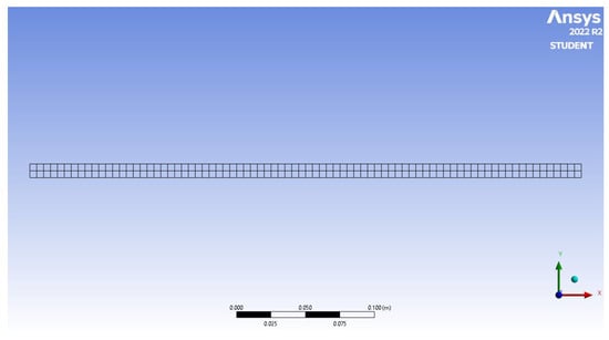
Vortex-induced vibrations occur when a bluff body placed in a fluid flow sheds vortices in an alternating pattern, generating oscillatory lift forces perpendicular to the flow direction. The vortex shedding frequency follows the Strouhal relationship:
where is the Strouhal number, U is the free-stream velocity, and D is the characteristic dimension of the bluff body.
The fluid–structure interaction can be described through the reduced velocity:
where is the natural frequency of the structure.
The lock-in (or synchronization) phenomenon occurs when the vortex shedding frequency approaches the structural natural frequency (). Under this condition, the shedding process synchronizes with the structural motion, leading to sustained oscillations. Although often considered undesirable in engineering applications, this phenomenon can be exploited for energy harvesting by converting mechanical oscillations into electrical energy.
VIV energy harvesters can be broadly classified according to the energy conversion mechanism and structural configuration. The main categories include:
- Piezoelectric VIV harvesters use piezoelectric materials bonded to vibrating structures, converting mechanical strain into electrical charges via the direct piezoelectric effect. Suitable for small-scale, low-power applications, their performance is strongly dependent on strain distribution and material properties.
- Electromagnetic VIV harvesters generate electricity through electromagnetic induction via the relative motion of a magnet and a coil driven by vortex shedding. They can achieve higher power outputs than piezoelectric devices but generally require larger oscillation amplitudes.
- Electrostatic VIV harvesters rely on variable capacitance mechanisms, where oscillations change the plate separation or overlap area, producing an electrical output. They are less common in fluid–structure interaction contexts due to the need for pre-charged circuits.
- Hybrid VIV harvesters combine two or more transduction mechanisms (e.g., piezoelectric and electromagnetic) to extend bandwidth and improve efficiency, leveraging the strengths of each technology over wider operating ranges.
Structurally, VIV harvesters can be divided into cylinder-based systems (rigid or flexible bluff bodies directly undergoing VIV) and wake-interaction systems (secondary structures placed in the wake of a bluff body), such as flexible membranes/plates and flag-type harvesters.
In the literature, several low-power energy-harvesting concepts based on the direct piezoelectric effect have been explored. These include ceramic cantilevers [20], cantilevers with cylindrical extensions [21], polymer cantilevers coupled with diaphragms [22], and jellyfish-inspired devices [23].
Wake-excited piezoelectric membrane harvesters have also attracted considerable attention. The pioneering study by Allen and Smits [24] demonstrated the feasibility of this concept through frequency-response measurements and particle image velocimetry (PIV). Building on this idea, Taylor et al. [25] developed a PVDF-based membrane harvester for ocean-current applications, while Techet et al. [26] experimentally confirmed that lock-in conditions could yield measurable power output. In addition, Doaré and Michelin [27] provided a more formal theoretical framework for the electromechanical behaviour of flow-excited flexible piezoelectric structures.
Among these membrane-based concepts, cylinder-wake-excited configurations are particularly attractive because of their simple structural design and their ability to provide effective electromechanical conversion under vortex-induced excitation, making them suitable for low-power applications in aquatic environments. However, their absolute power output may remain limited when the mechanically available energy is modest, and therefore strongly depends on the specific flow and structural configuration. In the present work, the expression “effective electromechanical conversion” refers to the capability of the device to convert deformation energy into electrical energy and should not be interpreted as implying high absolute power output under all operating conditions.
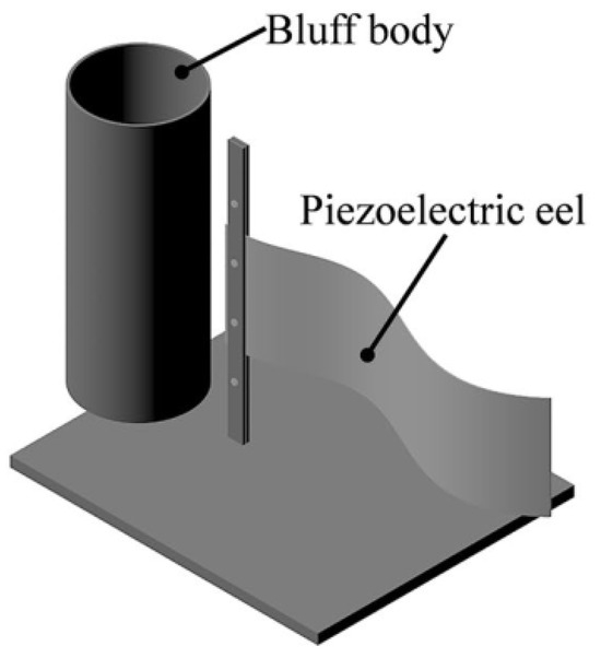
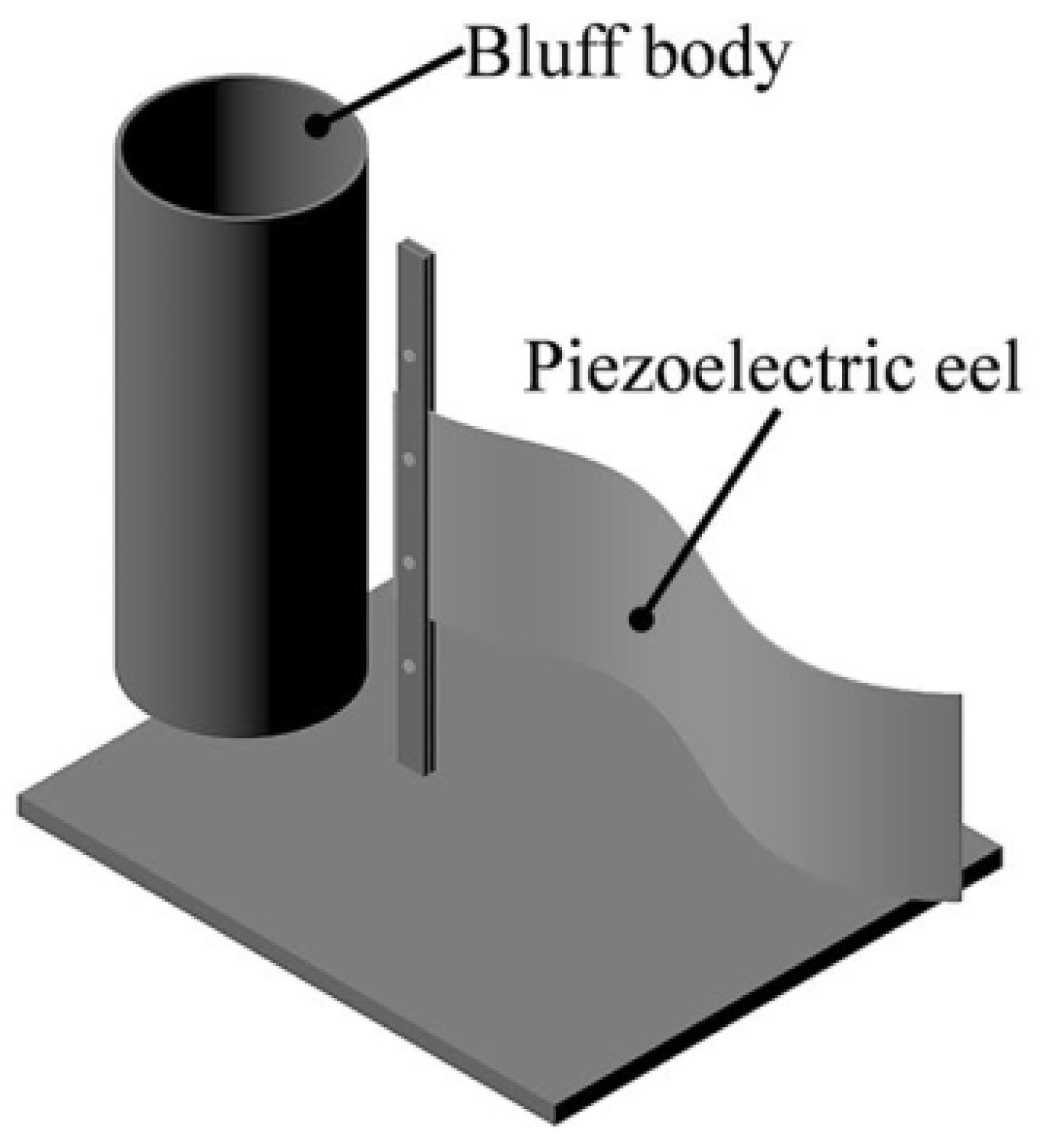
A typical configuration consisting of a fixed cylindrical bluff body positioned upstream of a flexible membrane equipped with surface-mounted piezoelectric patches is illustrated in Figure 1. The unsteady pressure field generated by the vortex shedding from the bluff body causes the membrane to deform, and this deformation is converted into electrical energy via surface-mounted piezoelectric patches. This layout shares similarities with flag-type harvesters, where a piezoelectric membrane oscillates freely in the flow. However, their typical low power output limits practical applications. To address this challenge, several investigations have been conducted.
Figure 1.
Schematic view of a cylinder-wake-excited piezoelectric membrane harvester (adapted from Ref. [28]).
Environmental effects have also been investigated. Latif et al. [29] studied the performance of a wake-excited piezoelectric membrane harvester in deep-water wave environments, finding that shorter wavelengths and shallower placements increased harvested energy by up to 65%. In a practical prototype study, Kamenar et al. [28] confirmed the feasibility of the concept in both laboratory and river flows, although the power densities remained modest, indicating the need for optimisation.
Recent modelling and experimental advances include Wang et al. [30] on parallel elastic plates with piezoelectric patches, Zhou et al. [31] on a low-startup-velocity VIV-driven piezoelectric membrane device for deep-sea applications, and Bucha et al. [32] on the effect of surface roughness on power output. Shahid et al. [33] explored the influence of wall proximity and bluff body shape, showing that inverted C-shaped cylinders improved power by 19%. Finally, Pan and Ji [34] demonstrated that multiple modified cylinders combined with piezoelectric cantilever beams in parallel could significantly increase both the voltage amplitude and the oscillation frequency.
Despite these advances, comprehensive studies of membrane-based VIV harvesters—particularly those integrating detailed fluid–structure interaction modelling with realistic piezoelectric power predictions—remain limited. The present work addresses this gap through a coupled CFD–FEM investigation of a novel membrane-based device optimised for open-flow operation in hydraulic environments.
3. Case Study and Its Mathematical Modelling
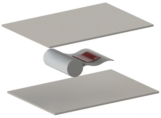
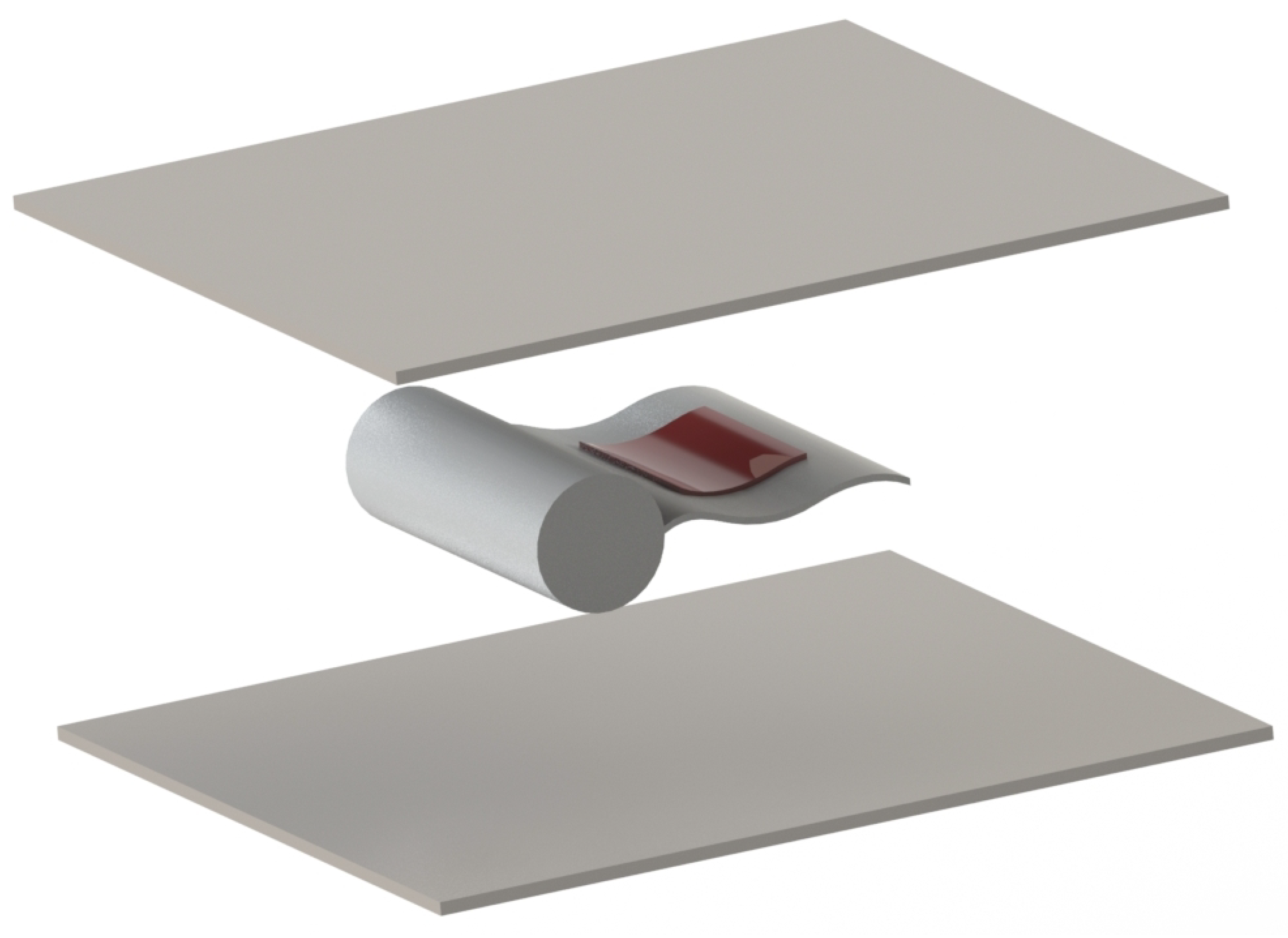
The present work investigates a membrane-based VIV energy harvester intended for operation in open-channel flows. The device consists of a fixed upstream cylinder that generates a periodic vortex street, inducing oscillations in a downstream flexible membrane equipped with surface-mounted piezoelectric patches, as shown in Figure 2. In this configuration, the unsteady pressure field produced by vortex shedding deforms the membrane, and the resulting strain can be exploited by piezoelectric patches bonded to its surfaces for electrical energy harvesting. It should be noted that the membrane is initially flat, while the curved shape observed during operation arises dynamically from the wake-induced loading and is not an imposed geometric feature. The study analyses how membrane geometry, material properties, and flow conditions influence energy conversion efficiency, employing a dedicated fluid–structure interaction (FSI) numerical framework.
Figure 2.
Schematic view of the analysed configuration.
The device performance is governed by strong fluid–structure coupling, as temporal and spatial variations in the pressure field directly affect membrane deformation. To capture this interaction, a coupled analysis was carried out in the Ansys environment, combining the unsteady Reynolds-averaged Navier–Stokes (URANS) approach for the CFD simulation with the finite element method (FEM) for the structural response. Accordingly, Section 3.1 details the fluid–structure coupling analysis, while Section 3.2 describes the computational domain and mesh generation.
3.1. The Fluid–Structure Coupling Approaches
In fluid–structure interaction analysis, two primary approaches are commonly employed: one-way coupling and two-way coupling [35].
In the one-way coupling approach, the pressure distribution obtained from the CFD analysis at a given time step serves as input for the FEM model, acting as an external force. However, there is no feedback loop from the FEM model to the CFD model, meaning that the structural response does not influence the fluid flow (see Figure 3a). This method provides accurate results when structural displacements are small, requires shorter simulation times, and allows for the simulation of flows at high Reynolds numbers. Its main limitations are that the influence of structural deformation on the fluid field is neglected and that fluid-induced damping effects must be introduced externally.
Figure 3.
Scheme of (a) the one-way and (b) the two-way approach for fluid-structural coupling analysis.
In contrast, the two-way coupling scheme involves a dynamic interaction between the CFD and FEM models. In this approach, the deformations calculated in the FEM model are fed back into the CFD model, establishing a feedback loop in which changes in the structural shape modify the pressure distribution, thereby altering the fluid flow and, in turn, the structural response (see Figure 3b). This exchange continues until a convergent solution is reached, providing a more accurate and realistic representation of the FSI. However, it requires small time steps to maintain accuracy, but at the same time it may become unstable for very short time steps (below 0.1–0.01 s), and is less effective in capturing high-frequency phenomena in either domain.
In this study, a one-way coupling strategy was selected for two main reasons. First, the relatively short convective timescale of the flow ( s), together with the correspondingly small numerical time step required for the transient CFD simulations, made two-way coupling computationally expensive and potentially detrimental to numerical stability over long transient runs. Second, for the range of materials tested—most of which exhibit relatively high stiffness—the deformation of the membrane is not expected to significantly alter the upstream vortex shedding process. Under this assumption, the upstream cylinder acts solely as a vortex generator exciting the membrane, while the membrane’s deformation does not influence the wake dynamics.
Accordingly, the fluid problem was solved using the commercial ANSYS Fluent solver to resolve the unsteady Reynolds-averaged Navier–Stokes (URANS) equations, whereas the structural problem was addressed using ANSYS Mechanical, with CFD results transferred as time-dependent pressure loads to the structural mesh.
For completeness, the governing equations underlying the adopted numerical framework are briefly recalled here. The fluid phase was described by the incompressible URANS equations, namely the continuity equation
and the momentum equation
where is the mean velocity vector, p is the pressure, is the fluid density, is the dynamic viscosity, and denotes the Reynolds stress tensor.
The structural response of the membrane was described by the dynamic equilibrium equation
where , , and are the mass, damping, and stiffness matrices, respectively, is the displacement vector, and represents the time-dependent pressure load transferred from the CFD solution.
Within the adopted one-way coupling strategy, the fluid solution determines the pressure field acting on the membrane, while the resulting structural deformation does not feed back into the fluid domain.
3.2. Geometry Description
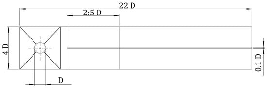
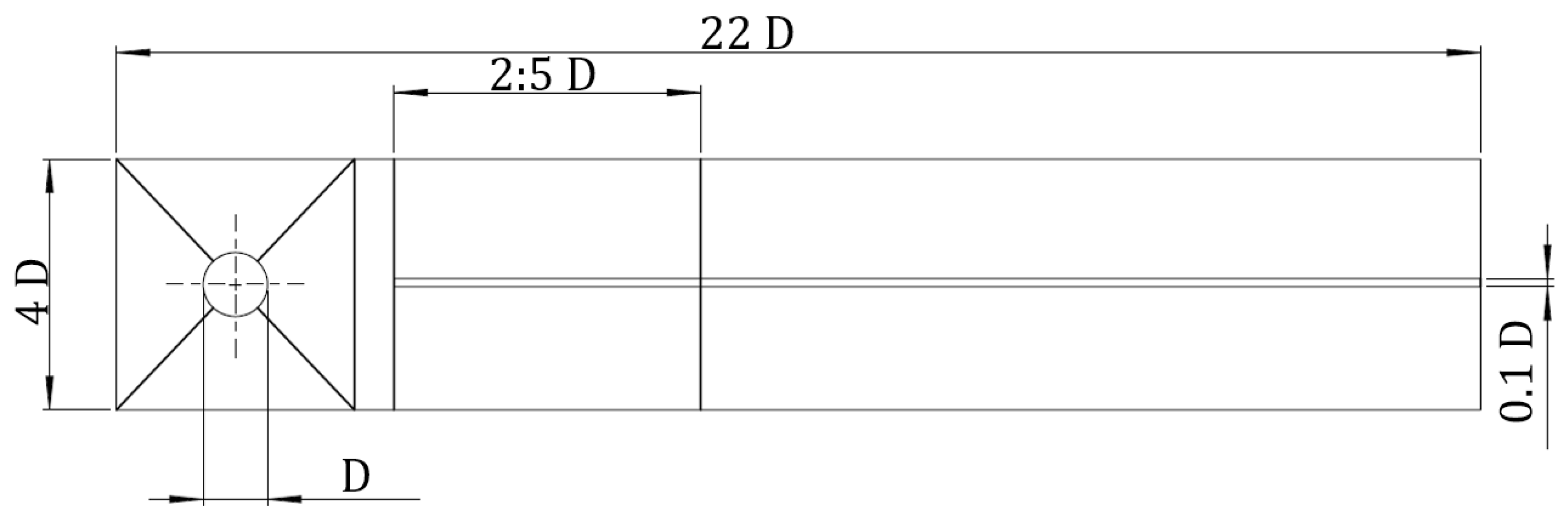
The computational model consists of a three-dimensional domain incorporating both the fluid and structural regions to enable direct data exchange within the ANSYS software suite. The geometry comprises an upstream cylinder with a diameter of m, followed by a downstream flexible lamina representing the energy-harvesting membrane (Figure 4). The cylinder diameter was selected to ensure lock-in conditions under the operating flow parameters considered in this study.
Figure 4.
Geometric layout of the simulation domain.
In this configuration, the unsteady pressure field generated by vortex shedding deforms the membrane, and the resulting strain can be exploited by piezoelectric patches bonded to its surfaces for electrical energy harvesting.
The fluid domain is modelled as a rectangular channel with dimensions , providing sufficient space for the development of a stable Kármán vortex street without interference from the inlet or outlet boundaries. Multiple lamina lengths were considered——to assess the influence of the aspect ratio on the dynamic response and energy conversion efficiency while maintaining a fixed lamina thickness of .
The lamina was positioned downstream of the cylinder to ensure that the vortex street developed fully before interacting with the membrane. This spacing avoids the near-wake region, where vortex formation is unstable and spatially irregular, and facilitates mesh generation by preventing complex contact regions between the cylinder and the membrane.
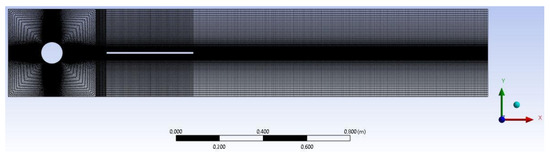
To accurately resolve wake dynamics and membrane–flow interaction, the fluid domain was discretised using a structured mesh, which offers higher numerical accuracy and stability than unstructured grids for this type of simulation. The mesh was divided into zones with local refinement in critical regions—specifically the cylinder surface, near-wake, and membrane location—where strong velocity gradients and vortex shedding occur.
This local refinement strategy was adopted to improve the resolution of separation, vortex roll-up, and wake–membrane interaction, while avoiding unnecessary mesh densification in low-gradient regions of the domain.
The mesh generation strategy was optimised for the configuration, which served as a reference for all subsequent cases.
3.3. Numerical Approach and Mesh Generation
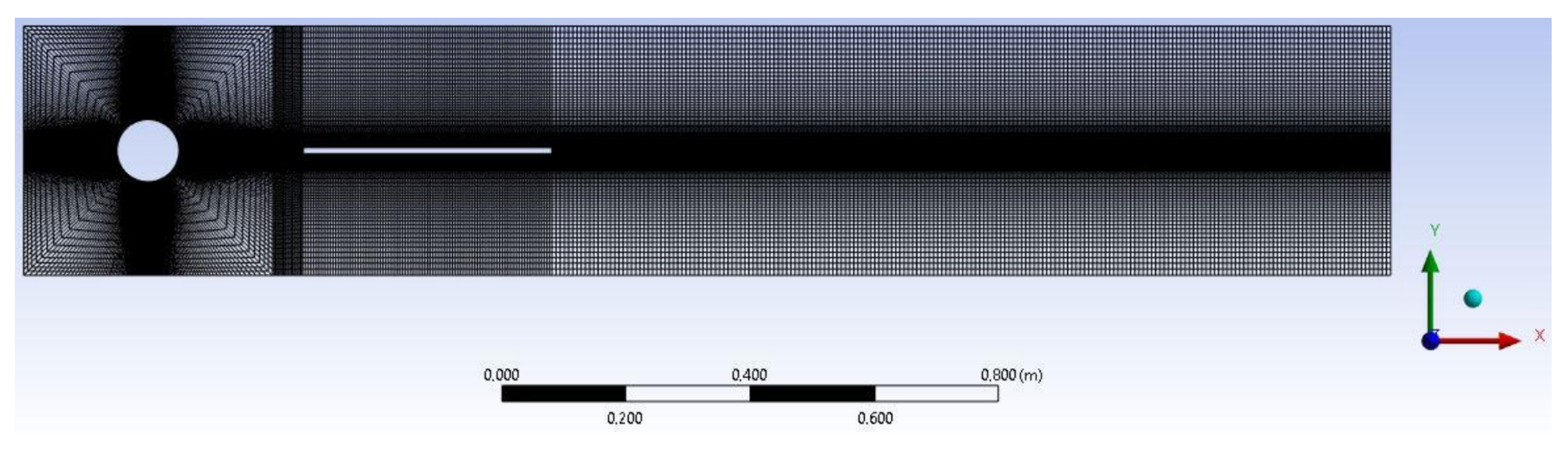
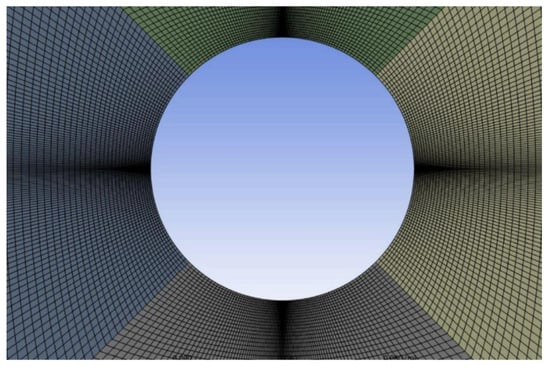
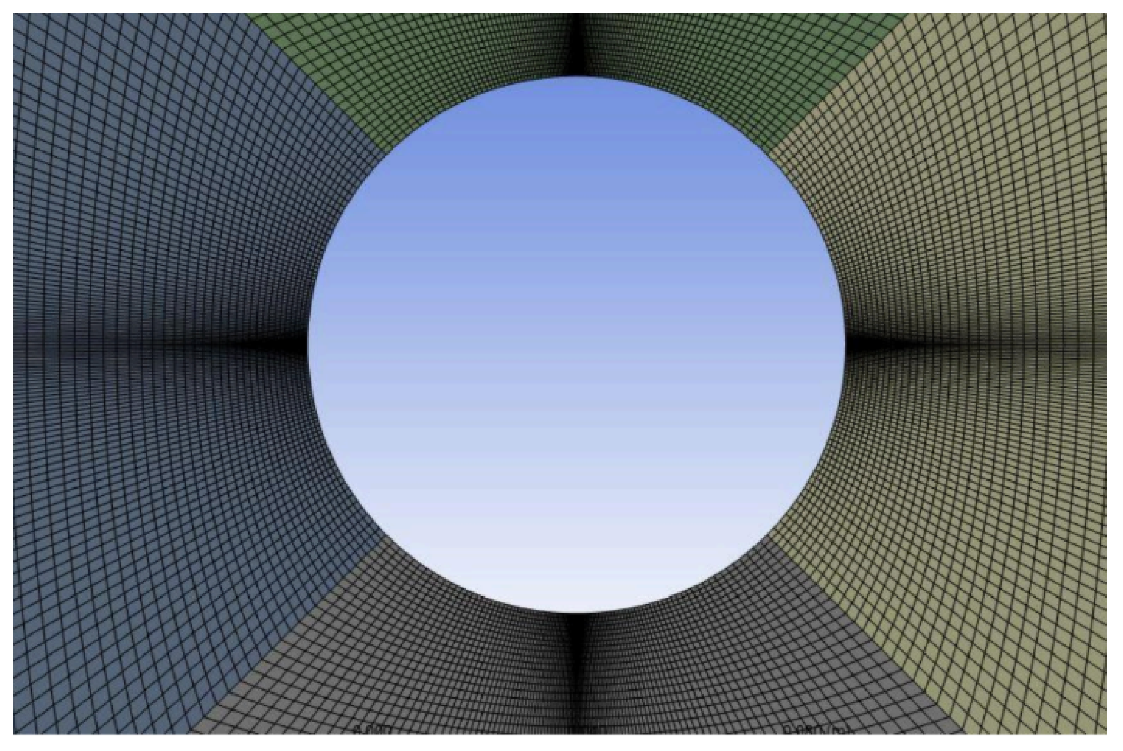
A high-resolution mesh was generated in the immediate vicinity of the cylinder and membrane (Figure 5) in order to accurately capture boundary-layer separation, vortex roll-up, and wake–membrane interactions. Wall-adjacent cells were refined to achieve , ensuring proper resolution of near-wall velocity gradients.
Figure 5.
CFD mesh details for .
To assess the sensitivity of the numerical solution to both mesh resolution and turbulence modelling, three grid levels (coarse, medium, and fine) were generated and tested in combination with three turbulence models: Spalart–Allmaras (SA), k– SST, and Transition SST.
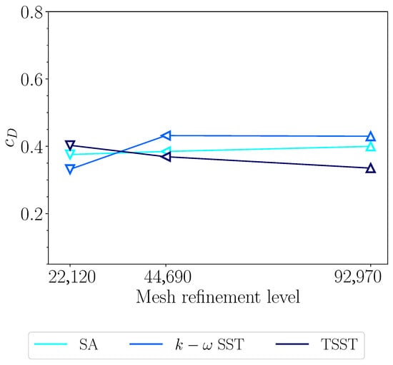
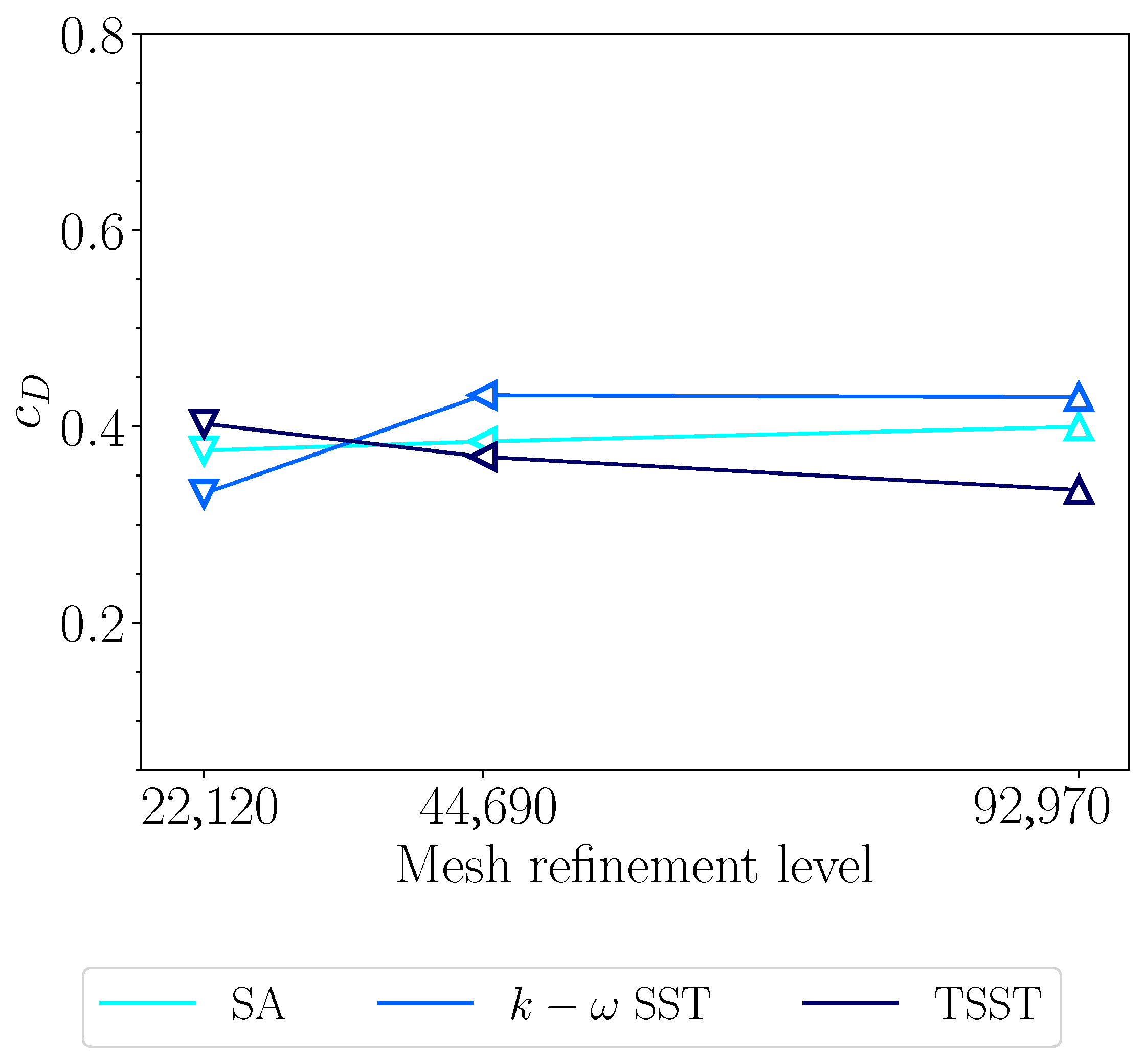
The influence of mesh resolution and turbulence model selection was first evaluated by analysing the drag coefficient of the cylinder at (Figure 6) in steady-state condition. The results show that, for the Spalart–Allmaras model, the predicted is essentially independent of mesh refinement. A slight variation with grid resolution is observed for the SST and Transition SST models, although differences remain limited.
Figure 6.
Average drag coefficient as a function of mesh refinement (coarse, medium, fine) and turbulence model (Spalart–Allmaras, k– SST, and Transition SST) at .
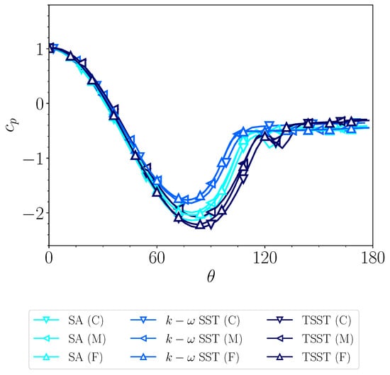
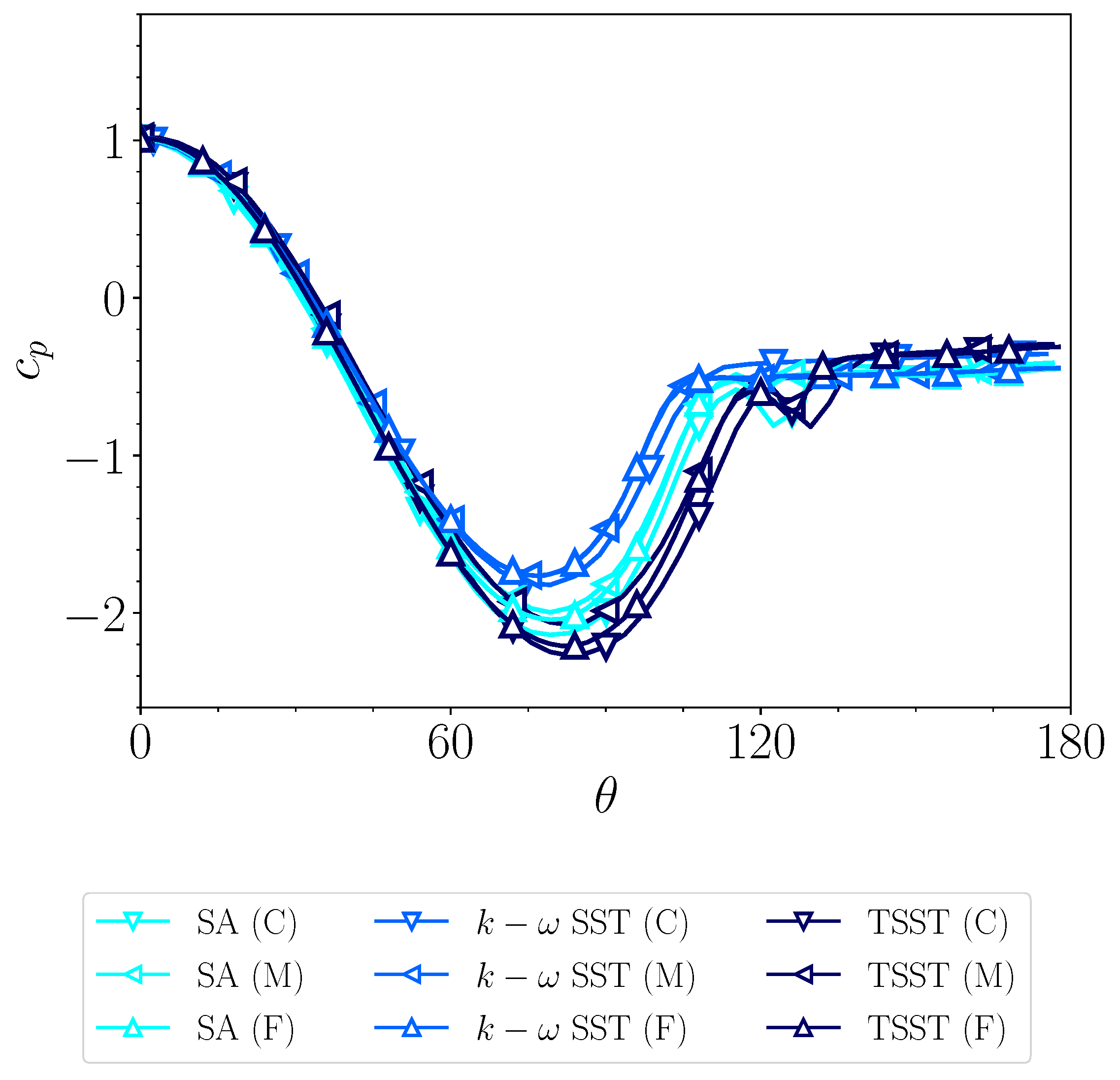
The sensitivity of the numerical approach was further investigated by comparing the steady-state pressure coefficient distribution along the upper half of the cylinder surface (Figure 7). The results confirm that the solution is only weakly dependent on mesh refinement for the quantities of interest. Some sensitivity to the turbulence model remains visible, particularly in the prediction of separation location.
Figure 7.
Pressure coefficient distributions on the upper half of the cylinder as a function of the angular coordinate . Comparison between turbulence models (Spalart–Allmaras, k– SST, and Transition SST) and mesh refinements (coarse, medium and fine) at .
Given the limited mesh dependency observed for the SA model and considering that the present work aims to provide a preliminary hydrodynamic assessment of the device rather than a high-fidelity turbulence study, the Spalart–Allmaras (SA) turbulence model [36] was adopted for the transient simulations. This model was selected for its reduced computational cost and its demonstrated capability to reproduce dominant vortex-shedding dynamics in bluff-body flows. Previous investigations [37] have shown that SA provides results consistent with more advanced turbulence closures in von Kármán vortex shedding configurations. The present numerical framework should therefore be interpreted as a preliminary and computationally efficient approach for comparative analysis, while a dedicated experimental validation for the specific configuration remains a relevant topic for future work.
Taking into account these considerations, the coarse grid was selected for the coupled simulations in order to limit computational effort while preserving accuracy in the prediction of global force coefficients and dominant shedding frequencies. The baseline CFD mesh consisted of approximately 225,000 quadrilateral elements (Figure 8), with gradual coarsening away from the cylinder–membrane region to maintain adequate far-field resolution.
Figure 8.
Mesh detail near the cylinder–membrane region.
The selected boundary conditions were as follows:
- Velocity inlet: uniform free-stream velocity m/s at the upstream boundary.
- Pressure outlet: fixed static pressure at the downstream boundary to allow free wake development.
- No-slip walls: applied to the cylinder, membrane, and channel surfaces.
Inlet turbulence conditions were set with an intensity of 5% and a turbulence viscosity ratio of 10.
The simulations were initialised using hybrid initialisation and advanced in time with a step , where is the convective timescale. A total physical time of 15 s was simulated to ensure the convergence of the vortex shedding pattern and the stabilisation of the force signals for structural coupling.
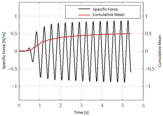
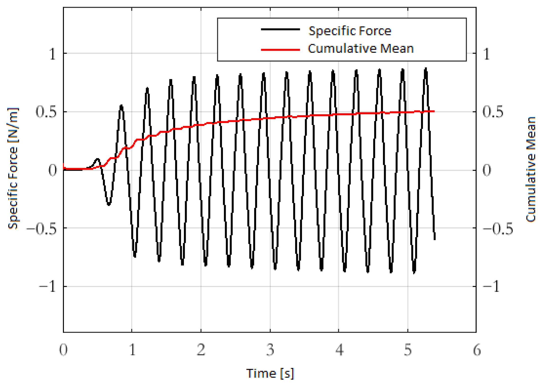
To verify the statistical stationarity of the simulated flow, the cumulative mean of the specific force acting on the membrane was monitored over time. Figure 9 reports the instantaneous force signal together with its corresponding cumulative mean. The cumulative average stabilizes well before the end of the 15 s simulation window, indicating convergence of the time-averaged quantities. This confirms that the selected simulation duration is sufficient to ensure statistical reliability of the reported results.
Figure 9.
Instantaneous specific force acting on the membrane surface and corresponding cumulative mean.
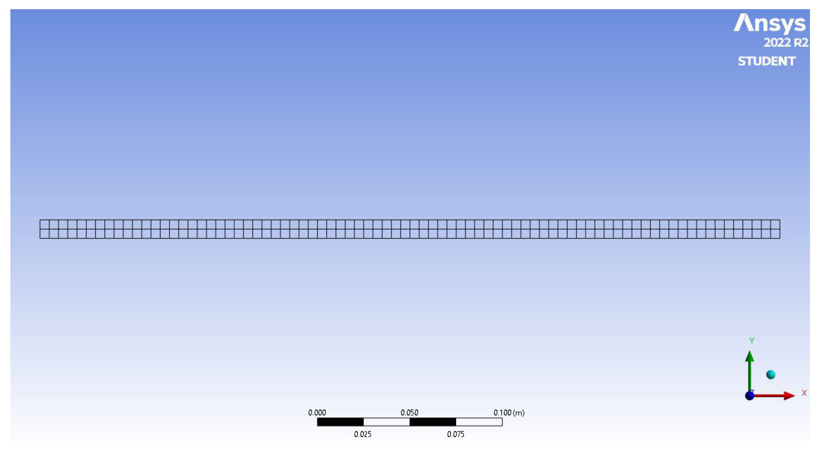
The structural domain consisted of the flexible membrane, modelled as a two-dimensional deformable body with in-plane degrees of freedom. For the case, the mesh employed 320 four-node quadrilateral (QUAD4) elements (Figure 10). The simplicity of the geometry allowed the use of low-order elements, ensuring satisfactory accuracy without excessive data generation—an important consideration for transient simulations.
Figure 10.
Structural mesh of the membrane for .
The structural boundary conditions were as follows:
- Clamped upstream edge: all translational degrees of freedom are fixed.
- Out-of-plane constraint: zero displacement in the z-direction to prevent twisting while allowing in-plane bending and oscillation.
Five membrane materials were selected and tested to investigate the effects of stiffness and density on vibration amplitude and harvested power: structural steel, titanium alloy, aluminium alloy, magnesium alloy, and polyethylene. Their mechanical properties are summarised in Table 1.
Table 1.
Mechanical properties of the materials considered in the FSI analysis.
The material properties directly influence the membrane response to fluid-induced pressure fields and, consequently, the overall energy-harvesting efficiency. While the one-way coupling assumption is valid for high-stiffness materials, where deformation has a negligible influence on the flow, its accuracy decreases for low-stiffness materials such as polyethylene, where large oscillations could alter the wake dynamics. This aspect is further discussed in Section 4.
4. Results and Discussion
This section presents and discusses the outcomes of the numerical investigation, focusing on both the fluid–structure interaction and the mechanical response of the membrane-based VIV harvester. The analysis is divided into two parts. The first part (Section 4.1) reports the results of the coupled CFD–FEM simulations, examining the influence of membrane length, material properties, and flow conditions on hydrodynamic behaviour, structural deformation, and deformation power. The second part (Section 4.2) focusses on the membrane mechanical analysis, assessing its flexural rigidity, deflection under self-weight, and the combined mechanical response when piezoelectric patches are attached. This integrated approach allows for a comprehensive evaluation of the system performance and limitations.
4.1. Results of the CFD–FEM Analyses
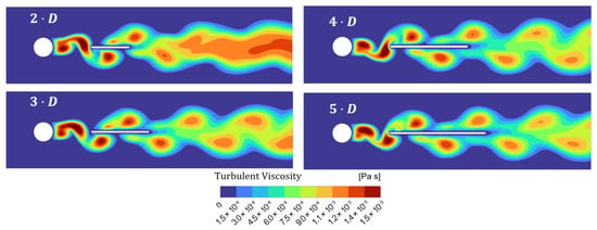
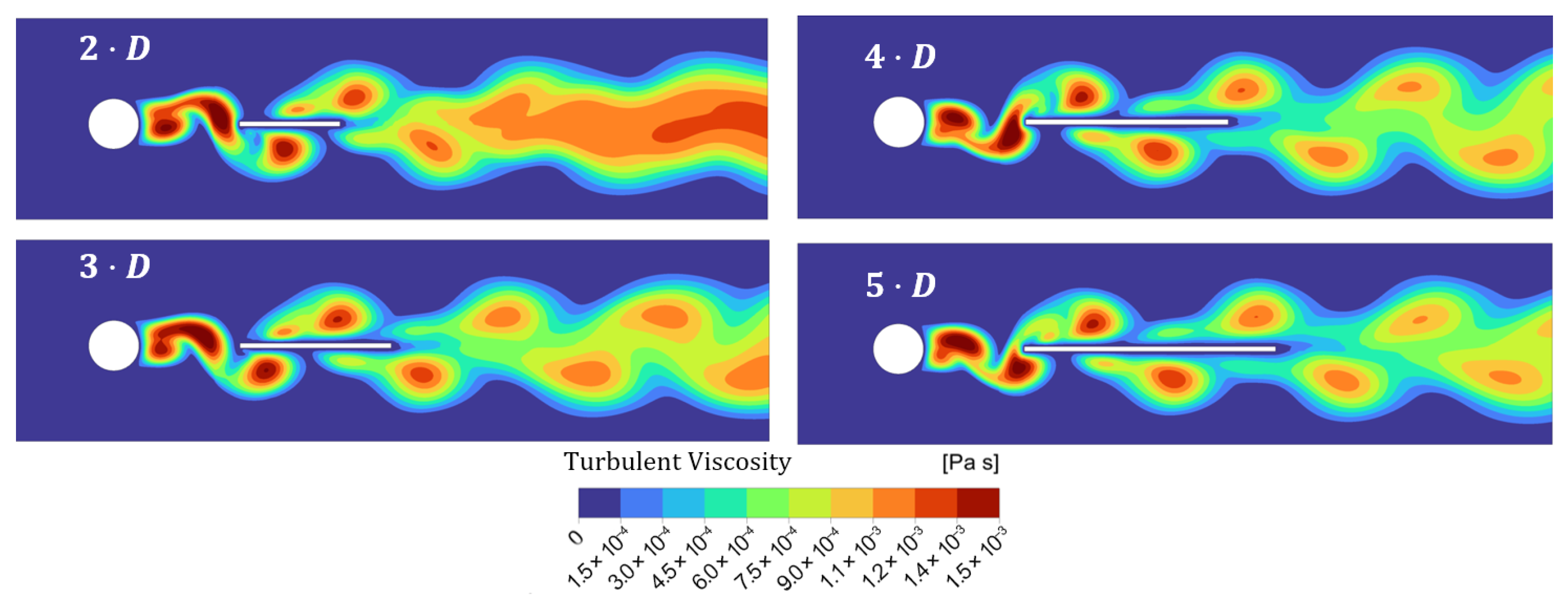
The hydrodynamic behaviour of the harvester was first examined to evaluate the effect of the lamina length on the development of the von Kármán vortex wake. Figure 11 compares the turbulent viscosity field for different configurations, showing that the lamina exerts only a minor influence on the vortex shedding frequency and wavelength. All cases show a shedding frequency of , corresponding to a wavelength of approximately in the lamina region.
Figure 11.
Effect of the lamina length on the von Kármán vortex street: turbulent viscosity field.
The reported shedding frequency corresponds to the dominant peak of the power spectral density of the force signal. The spectral resolution is given by , where T is the total sampling duration. In the present simulations, the selected time window ensures sufficient frequency resolution to accurately identify the primary vortex shedding mode. No significant higher harmonics or secondary peaks were detected in the analysed spectra, indicating that the flow response is dominated by a single coherent shedding frequency.
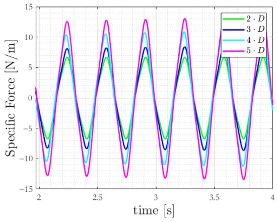
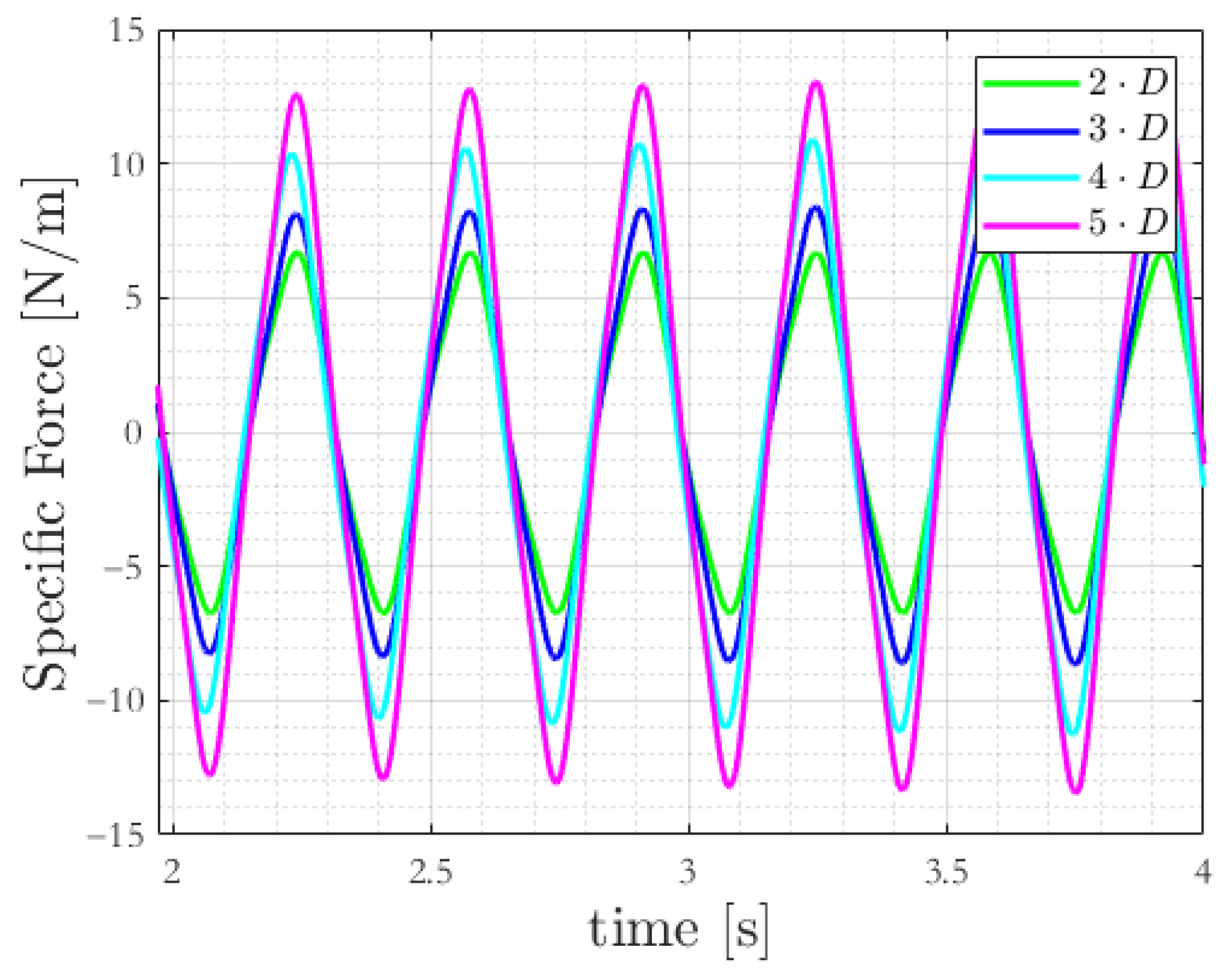
This observation is confirmed by the evolution of the normal force per unit depth acting on the membrane (Figure 12). While the shedding frequency remains essentially unchanged, the force amplitude increases proportionally with the lamina length.
Figure 12.
Normal force trend on the membrane surface.
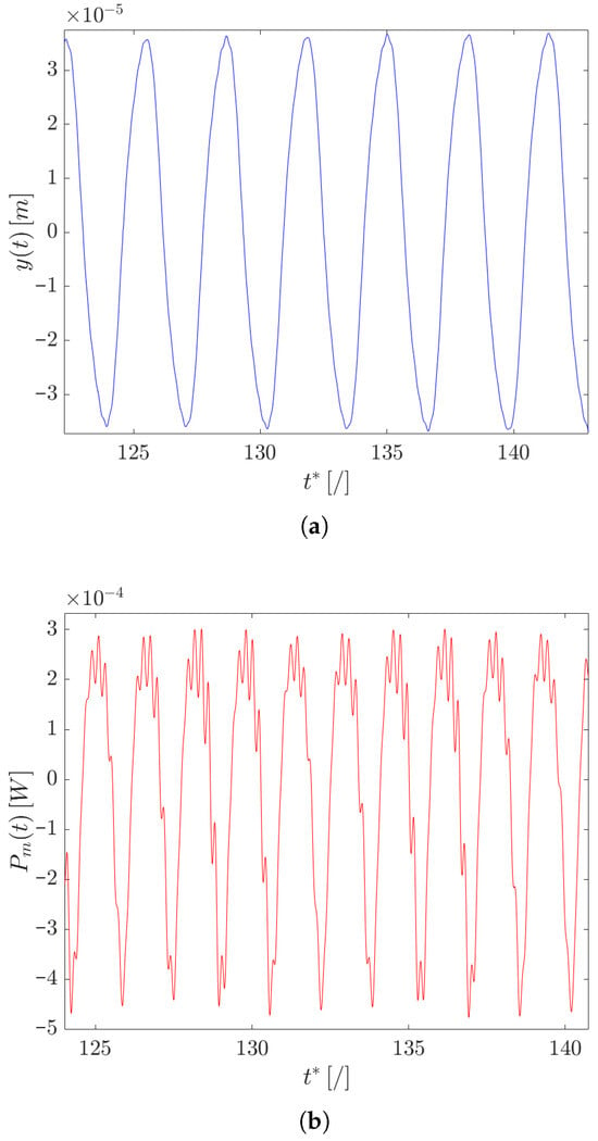
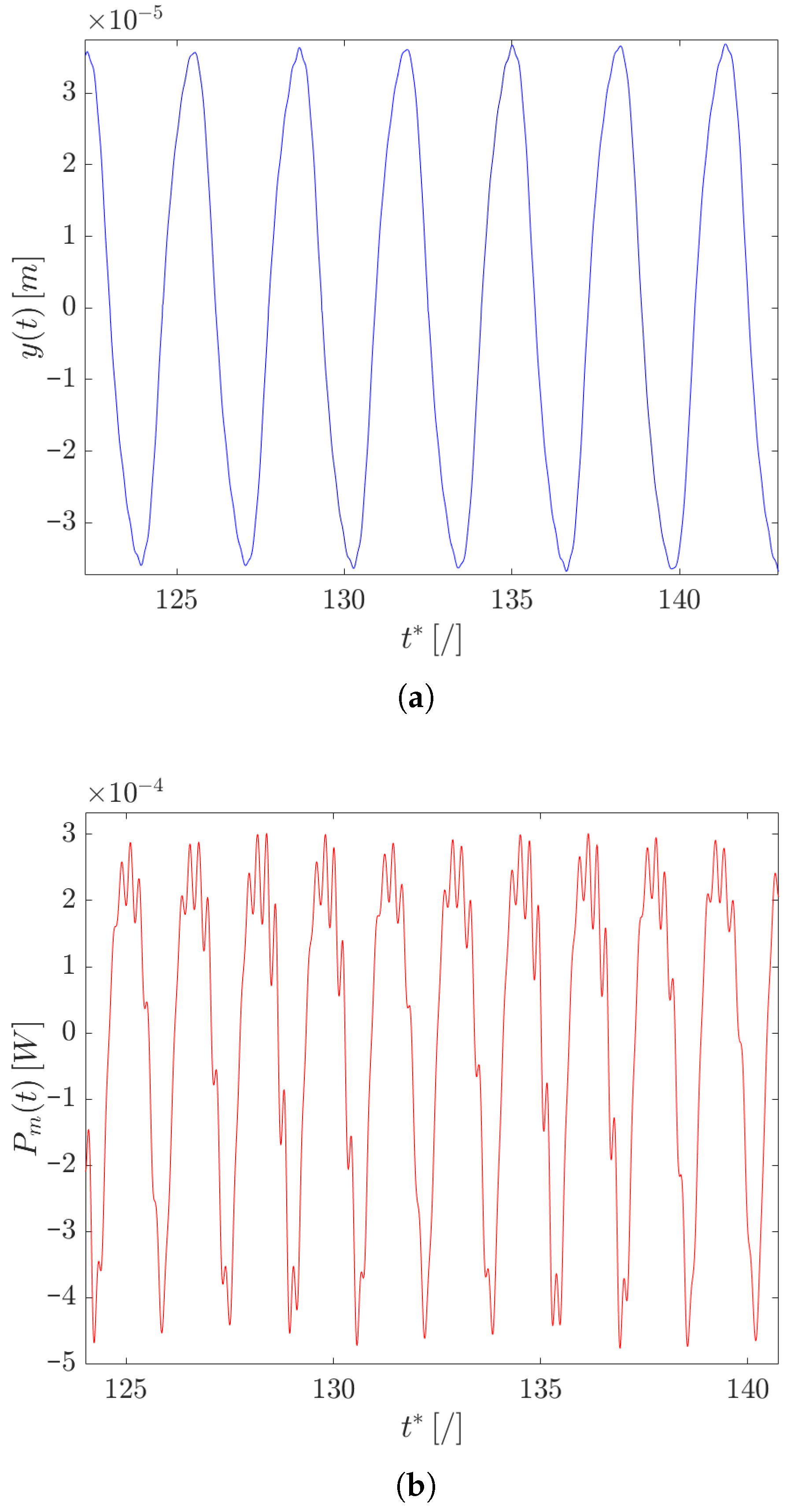
Since the harvested energy is strictly connected with the membrane deformation, the structural response was investigated by analysing the spatial average displacement and the deformation power . Figure 13 shows this response for the case with a titanium lamina.
Figure 13.
Spatial average displacement (a) and deformation power (b) of the lamina over the non-dimensional time , for and a titanium alloy lamina.
The displacement exhibits an almost sinusoidal waveform, indicating that a single-degree-of-freedom model can approximate the global motion. Conversely, the deformation power shows a more complex profile, with high-frequency components superimposed on the primary oscillation.
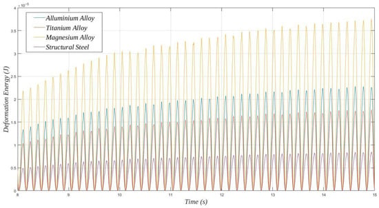
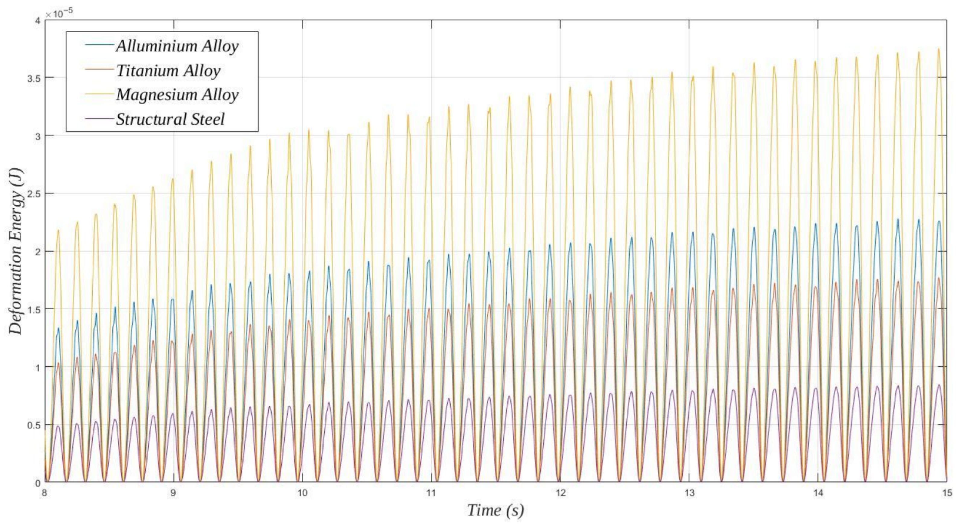
A comparison between the different materials is shown in Figure 14, reporting the time evolution of the deformation energy for different metallic materials (). The oscillations have the same frequency for all materials, but the peak energy increases with Young’s modulus.
Figure 14.
Deformation energy for with different metallic materials.
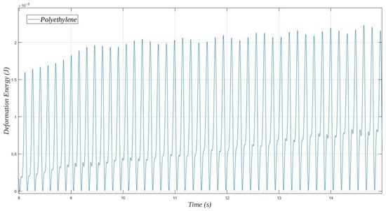
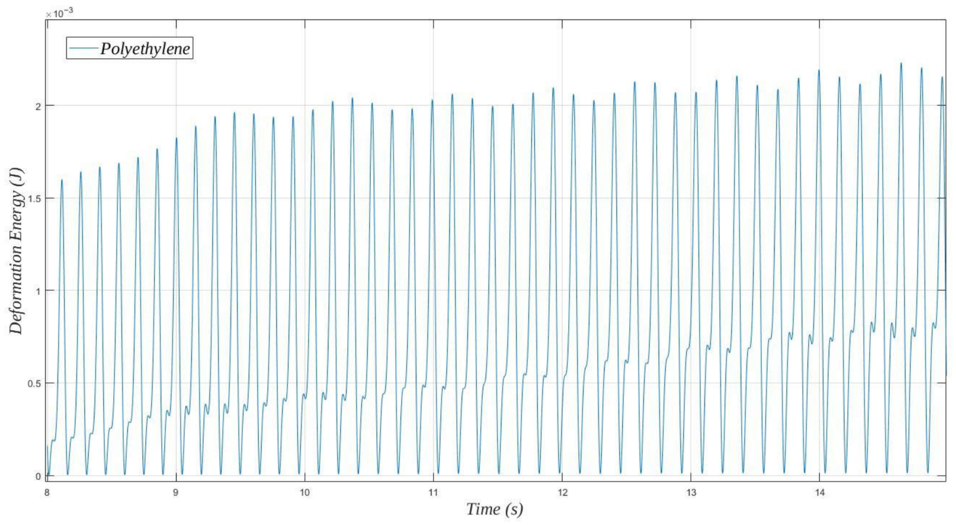
Polyethylene, however, produces significantly higher energy values (Figure 15) but with a more irregular temporal pattern, suggesting multiple contributing frequencies.
Figure 15.
Deformation energy for with polyethylene.
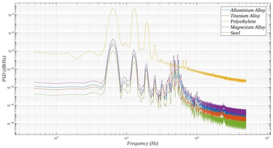
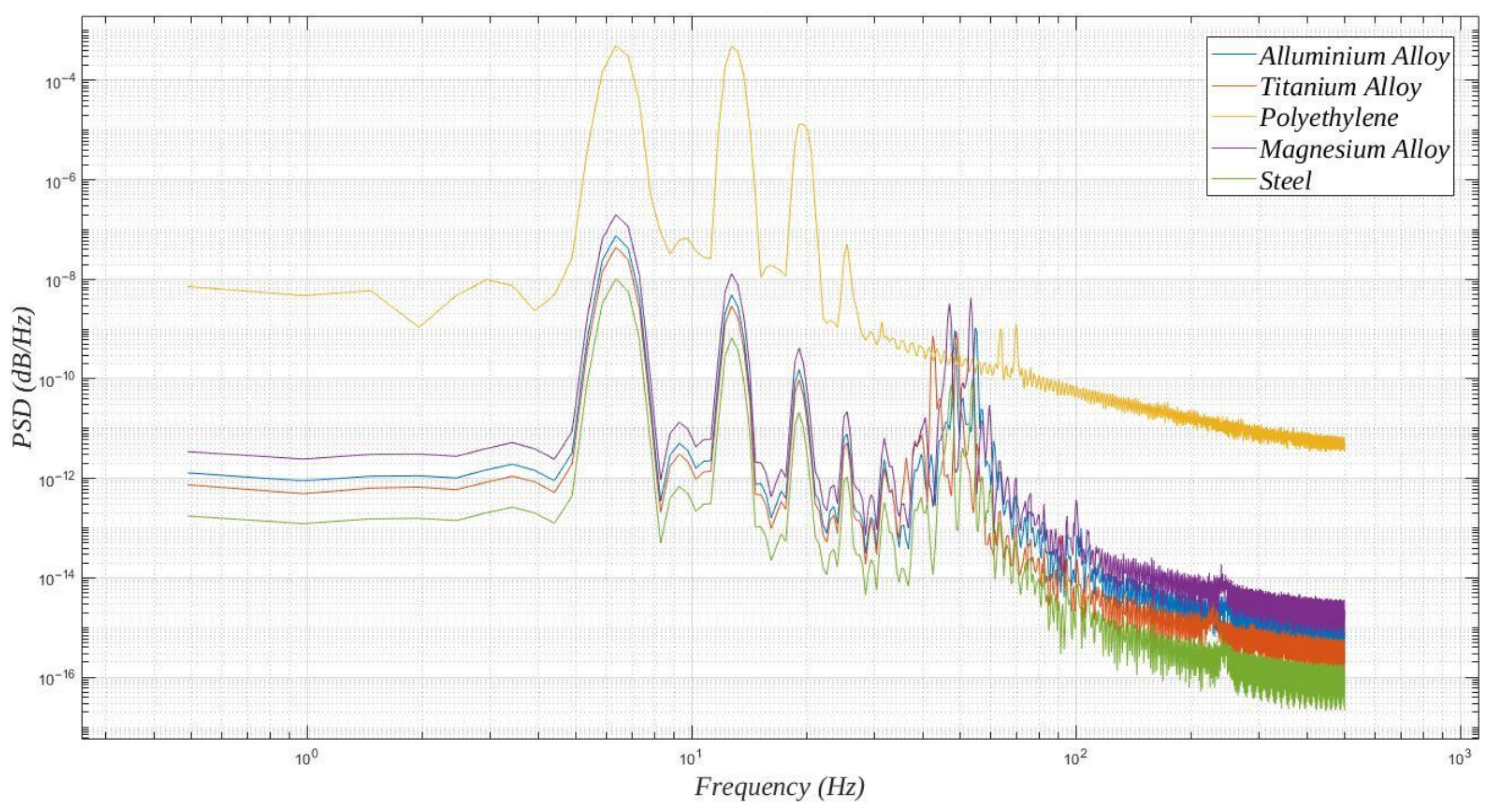
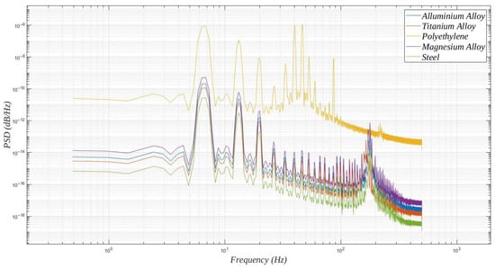
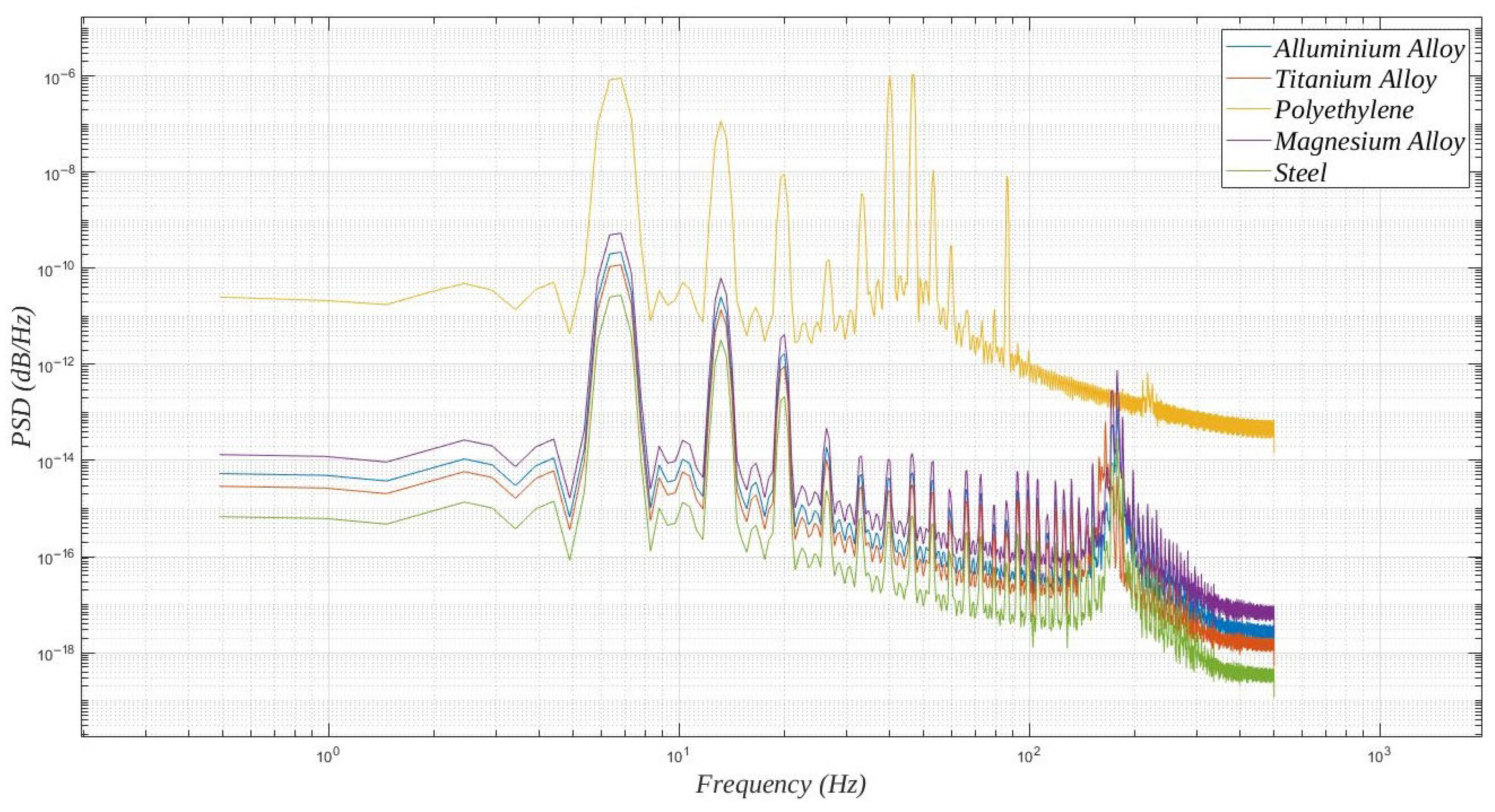
To analyse the correlation between deformation power and frequency, the power spectral density (PSD) for the different materials was also determined. Figure 16 highlights a dominant peak at , with second and third harmonics at and , respectively. Polyethylene concentrates most of the spectral power at low frequencies, more in line with the vortex shedding frequency, whereas metals exhibit a wider spectrum with secondary peaks around .
Figure 16.
PSD of the deformation power for and different materials.
The superior performance of polyethylene is also confirmed in terms of RMS deformation power per unit of membrane depth () (Table 2). Polyethylene exhibits a power two orders of magnitude higher than that of the other materials.
Table 2.
RMS deformation power per unit depth for .
It should be emphasized that the values reported in Table 2 refer to the mechanical deformation power available in the membrane. The actual electrical output of a piezoelectric harvester depends not only on this available mechanical energy but also on the electromechanical coupling characteristics of the material, electrical load matching conditions, and power conditioning strategy.
In membrane-based piezoelectric harvesting systems, the overall mechanical-to-electrical conversion efficiency reported in the literature spans a wide range, depending on structural configuration and excitation mechanism [38]. Therefore, the mechanical power values presented in this study represent the upper bound of the energy potentially available for conversion rather than the directly harvested electrical output.
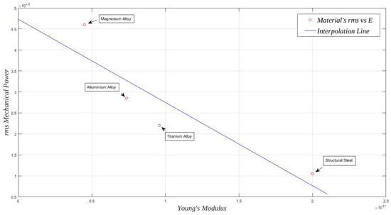
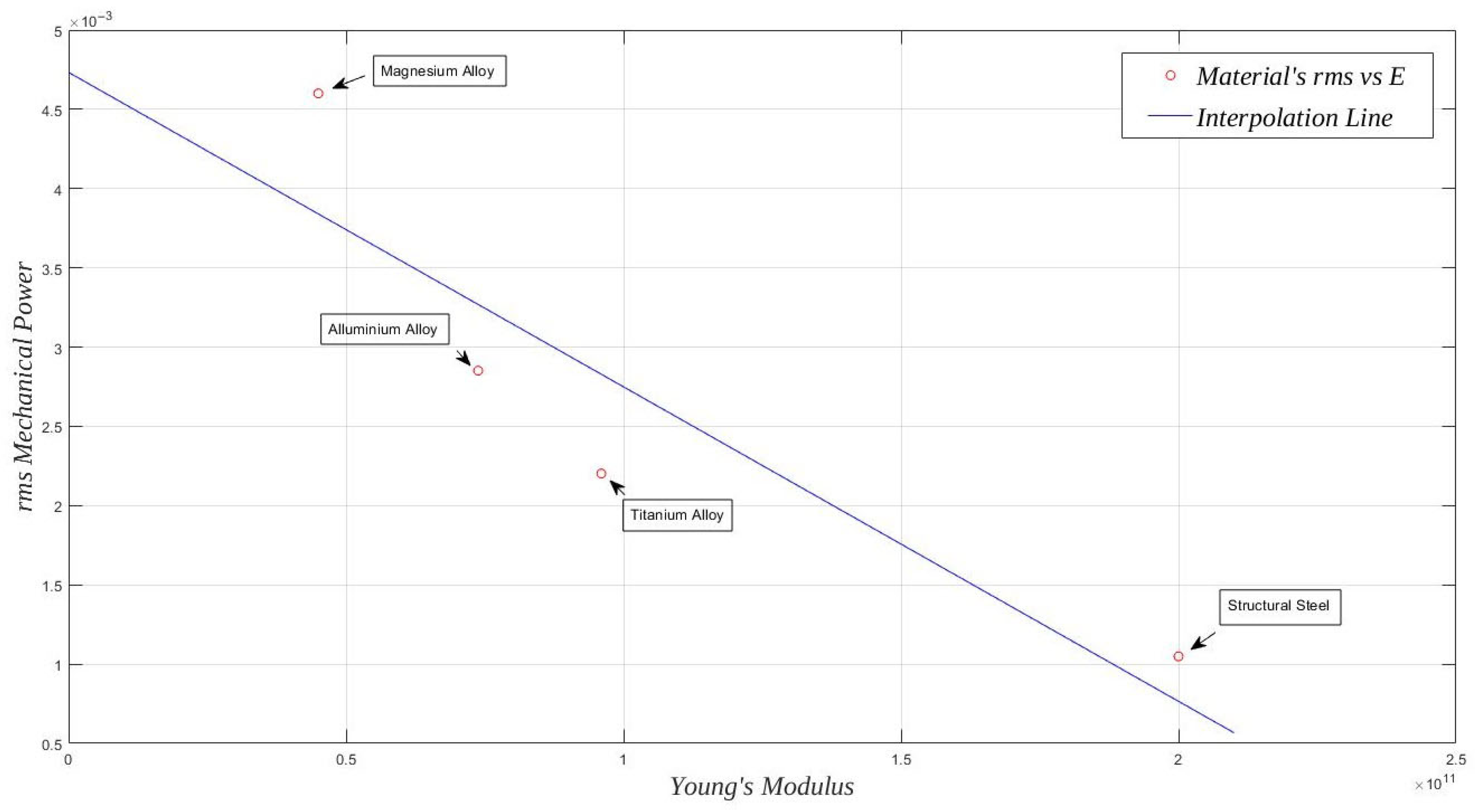
This behaviour is primarily associated with the lower Young’s modulus of polyethylene, which promotes larger deformation amplitudes under identical flow excitation. For the investigated metallic materials, the relationship between RMS deformation power and Young’s modulus is illustrated in Figure 17.
Figure 17.
RMS deformation power as a function of Young’s modulus for metallic materials, .
To quantitatively assess such relationship, a Pearson correlation analysis was conducted. The resulting coefficient () indicates that no significant linear correlation exists within the considered dataset. Although variations in deformation power are observed among materials, these differences cannot be described by a simple linear dependence on stiffness. A more extensive parametric analysis including additional intermediate modulus values would be required to determine whether a nonlinear relationship may exist.
Although no statistically significant linear correlation is observed, materials with lower Young’s modulus generally exhibit higher values within the limited set of cases analysed.
For shorter lamina (), the main spectral peaks remain at the same frequencies (Figure 18), but the high-frequency content is more pronounced than in the cases observed for . Probably due to the shorter length, the membrane can capture only part of the organised vortex development and is therefore subjected to a more irregular turbulent flow. As a consequence, the deformation power is distributed over a wider range of frequencies, reducing the deformation power density in the frequency region close to the vortex shedding frequency ().
Figure 18.
PSD of the deformation power for and different materials.
This is clearly reflected in Table 3, which lists the RMS deformation power for the different values of . The cases are characterised by an RMS deformation power slightly lower than that obtained with , but still comparable.
Table 3.
RMS deformation power per unit depth for various ratios.
On the other hand, is orders of magnitude smaller for the cases with and . A possible explanation for this behaviour is related to the development of vortex shedding and its interaction with the membrane. Since the wavelength of the vortex shedding is approximately , the membrane length directly affects the number of vortices that can be effectively captured. Given that the membrane is positioned at a distance of 1D from the cylinder, the membrane is not exposed to a full shedding cycle but only to a part of it, which may exert a damping effect on its overall deformation. Conversely, the membrane interacts with an entire shedding period, leading to a stronger and more coherent excitation, also enhanced by possible resonance effects. For the case, the membrane is again subjected to partial periods, which could reintroduce a similar damping behaviour. This hypothesis is supported by the turbulence intensity distributions shown in Figure 11.
In terms of materials, polyethylene is consistently the best performer for all of the considered lengths, confirming the key role that Young’s modulus plays in power extraction. However, although polyethylene exhibits the highest mechanical deformation power, the absolute values of this power are limited, and these values do not consider the influence of the plate thickness and the presence of patches on the membrane surface. To investigate this aspect, a mechanical analysis was conducted.
4.2. Membrane Mechanical Analysis
To better highlight the role of the material in the configuration performance, a complementary mechanical analysis was carried out. This additional investigation aims to characterise in detail the behaviour of the membrane itself, isolating its structural response and evaluating the effects of material properties, geometry, and the presence of piezoelectric patches on its deformation and flexibility.
The membrane was modelled as a bending plate/lamina that deflects under external pressure loads. Piezoelectric patches are glued to both sides of the plate to convert strain into electrical power. Their presence affects the membrane behaviour since it influences the system flexural rigidity. In particular, the flexural rigidity of a plate is
where E is Young’s modulus and is Poisson’s ratio.
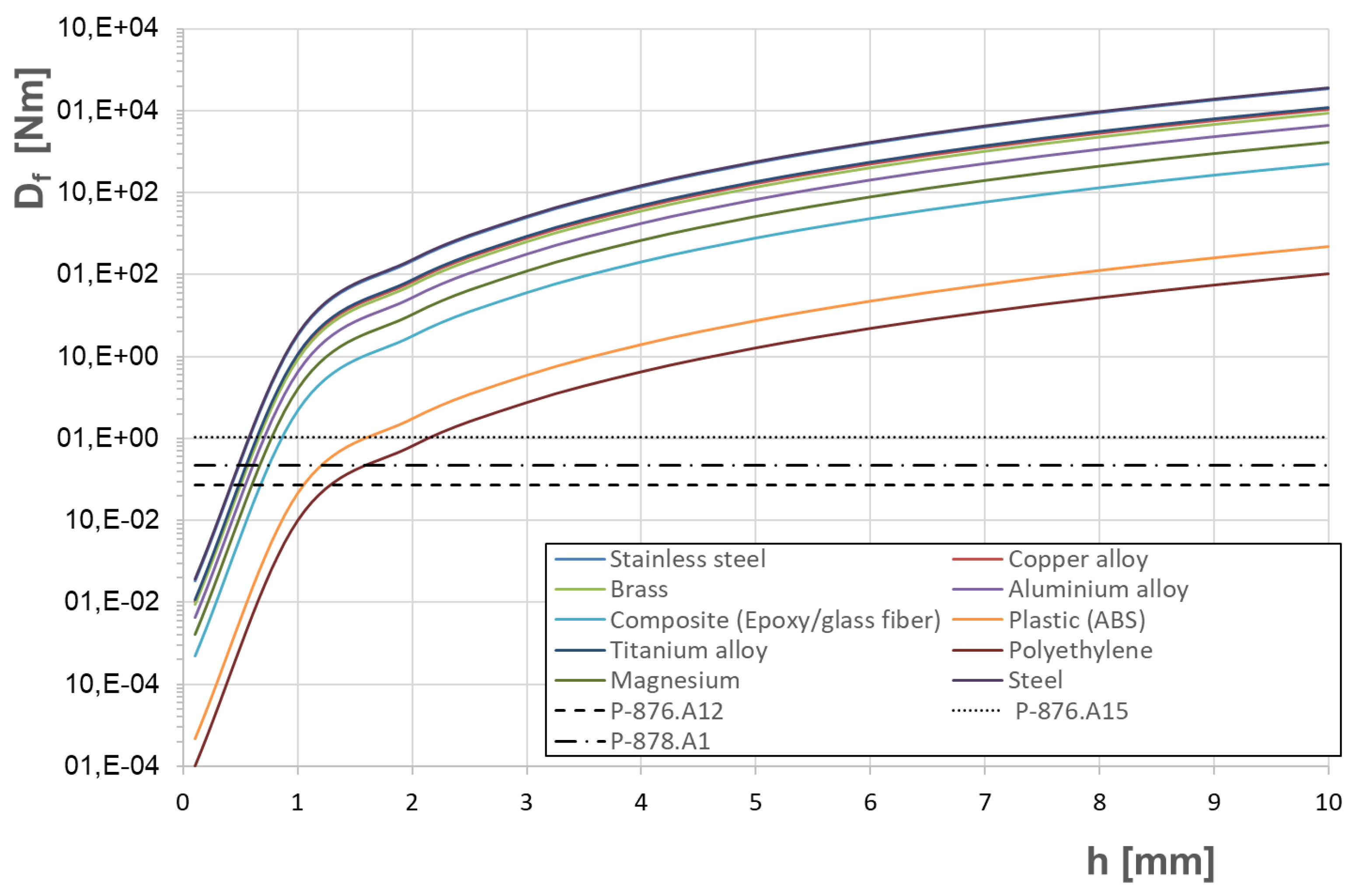
From this equation, it is clear that the flexural rigidity of the membrane depends on the membrane thickness h and the material characteristics, as shown in Figure 19, which reports for various materials. Notably, is directly proportional to the material Young’s modulus (E), indicating that materials with higher E exhibit greater flexural rigidity. For example, stainless steel shows higher compared to ABS plastic with equivalent h. Additionally, increases exponentially with the cube of the thickness (), leading to higher values of for thicker materials. In the same figure, the flexural rigidity of various commercial piezoelectric patches (P-876.A12, P-876.A15, and P-878.A1 from PI Ceramics) is also reported. However, since patches have defined thicknesses, their flexural rigidity does not change with the membrane thickness h, resulting in horizontal lines.
Figure 19.
Flexural rigidity for different materials as a function of the thickness of the plate h. The flexural rigidity of the PI Ceramics piezoelectric patches are also plotted for comparison.
The mechanical behaviour of the combined plate–patch system can fall into three different regions, depending on the membrane thickness h: (i) an upper region governed by the flexural rigidity of the material (); (ii) a middle region where both the plate and the patch have similar flexural rigidities (); and (iii) a lower region governed by the flexural rigidity of the piezoelectric patch (). For example, in the case of an ABS plastic plate and the P-876.A15 patch, of ABS dominates over of the patch for mm (upper region), while the mechanical behaviour is governed by the piezoelectric patch for mm (lower region). To limit the influence of the patch on the plate deformation, thicker membranes are suggested; however, the thicker the membrane, the smaller the membrane deflection as a consequence of the vortex shedding interaction.
To better understand this mutual influence, the results obtained from the CFD–FEM simulations (see Section 4.1) can be analysed considering the possible influence of the patch presence on the membrane. To minimise the impact of the patch on the membrane behaviour, the patch model with the lower flexural rigidity can be considered (P-876.A12). It is worth recalling that the results refer to a membrane with a thickness of 1 mm.
According to Figure 19, the presence of the patch does not affect the deformation power of all material membranes, with the exception of ABS and polyethylene. In these last cases, ABS is characterised by a slightly smaller rigidity, and the impact is expected to be negligible. In contrast, the polyethylene results will be more affected by glueing the patch onto the membrane surface, further reducing the extracted power.
In conclusion, the mechanical assessment of the flag-like VIV harvester indicates that the lamina can only behave as a non-rigid flag-like structure at small thicknesses for the studied materials. However, this behaviour is affected by the glued piezoelectric patches, as their stiffness may govern the deformation, significantly reducing strain levels and, thus, electrical power output. From a purely mechanical standpoint, this configuration appears to offer limited performance as an energy-harvesting system with the existing analysed commercial patches. However, the use of innovative, thinner materials properly combined with the development of more flexible patches can open the path for possible improvements.
Although the present results highlight the potential of the proposed concept for low-power hydraulic monitoring, they also reveal important practical limitations. To provide a more balanced engineering interpretation, the main advantages, limitations, and practical implications of the proposed wake-excited membrane harvester are summarised in Table 4.
Table 4.
Main advantages, limitations, and practical implications of the proposed wake-excited piezoelectric membrane harvester.
5. Conclusions
This work presented a numerical assessment of a cylinder-wake-excited piezoelectric membrane vortex-induced vibration (VIV) energy harvester for open-channel applications, with particular focus on the influence of membrane material properties and geometric parameters on deformation response and available mechanical power.
The key findings are:
- Hydrodynamic behaviour. The membrane has a limited influence on vortex shedding frequency and wavelength, while the force amplitude increases with membrane length. None of the investigated configurations reached a full lock-in condition within the explored parameter range.
- Material effects. Membrane stiffness strongly influences deformation amplitude and RMS mechanical power. Polyethylene exhibited the highest deformation power due to its low flexural rigidity, whereas metallic membranes generated lower strain energy levels under identical flow conditions. The analysed configurations, however, correspond to a baseline (non-optimised) thickness and geometry intended for comparative material screening.
- Spectral characteristics. The response is dominated by the primary vortex shedding frequency, with no significant broadband contributions. Membrane length affects oscillation amplitude but does not substantially modify the dominant shedding mechanism.
- Mechanical constraints. Flexural rigidity analysis indicates that the stiffness of bonded piezoelectric patches can significantly alter the effective structural behaviour of thin membranes, potentially suppressing deformation and limiting the available mechanical energy.
- Design implications. The results highlight the importance of material tuning and structural compliance in VIV-based harvesters. Future developments should explore optimised ratios, lightweight composite membranes, and low-stiffness, high-efficiency piezoelectric integrations to enhance deformation response and energy extraction.
Overall, the present study should be interpreted as a preliminary comparative assessment aimed at establishing a material-selection and modelling framework rather than a fully optimised harvesting configuration. The absolute power levels reported reflect the baseline geometry and operating conditions adopted for this analysis. Therefore, while the current configuration yields only modest practical output, the results provide a consistent basis for identifying the key physical and structural parameters governing the harvesting potential of wake-excited membrane devices.
From a practical perspective, the proposed concept offers several attractive features, including structural simplicity, passive wake excitation, and suitability for low-power hydraulic monitoring applications. At the same time, the present results highlight relevant limitations. In the investigated baseline configuration, no full lock-in condition was achieved, and the stiffness of currently available bonded piezoelectric patches may significantly suppress membrane deformation, thereby limiting the practically harvestable energy. The viability of this concept therefore depends not only on the wake-induced excitation mechanism itself, but also on the combined optimisation of membrane compliance, patch flexibility, and geometric tuning.
The main scientific contribution of this work lies in the definition of a comparative CFD–FEM and mechanical assessment framework capable of identifying the influence of membrane material and geometry on deformation response and mechanically available power in open-channel flows. In this sense, the study provides both physical insight into the governing wake–membrane interaction and practical guidance for the preliminary design of piezoelectric membrane harvesters.
Future work should therefore focus on geometric optimisation, the development of more compliant membrane–patch assemblies, the integration of a fully coupled electromechanical model including the external circuit, and the experimental validation of the proposed harvesting concept under realistic open-channel operating conditions. It should also be emphasised that conversion efficiency and absolute power output are distinct quantities: although the electromechanical conversion process may be effective, the harvested electrical power ultimately depends on the mechanical energy made available by the flow–structure interaction.
Author Contributions
Conceptualization, G.Z., F.N., A.B. and G.C.; Data curation, G.Z., F.N. and A.B.; Formal analysis, G.Z., F.N., M.C., A.B. and G.C.; Funding acquisition, G.C.; Investigation, G.Z., F.N., M.C., A.B. and G.C.; Methodology, G.Z., F.N., A.B. and G.C.; Project administration, G.C.; Supervision, A.B. and G.C.; Validation, G.Z., F.N., M.C. and A.B.; Visualization, F.N.; Writing—original draft, G.Z., A.B. and G.C.; Writing—review and editing, F.N. and M.C. All authors have read and agreed to the published version of the manuscript.
Funding
This research was funded by the European Climate, Infrastructure and Environment Executive Agency research and innovation programme under grant agreement number 101084362. However, the views and opinions expressed are those of the authors alone and do not necessarily reflect those of the European Union. Neither the European Union nor the granting authority can be held responsible for them.
Institutional Review Board Statement
Not applicable.
Informed Consent Statement
Not applicable.
Data Availability Statement
The data presented in this study are available on request from the corresponding author due to privacy reasons.
Conflicts of Interest
The authors declare no conflicts of interest.
References
- Onyena, A.P.; Sam, K. The blue revolution: Sustainable water management for a thirsty world. Discov. Sustain. 2025, 6, 63. [Google Scholar] [CrossRef] [Scilit]
- Lindner, A.; Stamm, J. Integrating Climate Change Adaptation and Water Resource Management: A Critical Overview. Standards 2025, 5, 4. [Google Scholar] [CrossRef] [Scilit]
- Borah, G. Urban water stress: Climate change implications for water supply in cities. Water Conserv. Sci. Eng. 2025, 10, 20. [Google Scholar] [CrossRef] [Scilit]
- Fooladivanda, D.; Domínguez-García, A.D.; Sauer, P.W. Utilization of water supply networks for harvesting renewable energy. IEEE Trans. Control Netw. Syst. 2018, 6, 763–774. [Google Scholar] [CrossRef] [Scilit]
- Latifi, M.; Zali, R.B.; Kerachian, R. Optimal energy harvesting plans in water distribution networks considering the stakeholders’ utilities. Energy Strategy Rev. 2024, 54, 101437. [Google Scholar] [CrossRef] [Scilit]
- Zulkifli, C.Z.; Garfan, S.; Talal, M.; Alamoodi, A.; Alamleh, A.; Ahmaro, I.Y.; Sulaiman, S.; Ibrahim, A.B.; Zaidan, B.; Ismail, A.R.; et al. IoT-based water monitoring systems: A systematic review. Water 2022, 14, 3621. [Google Scholar] [CrossRef] [Scilit]
- Colglazier, W. Sustainable development agenda: 2030. Science 2015, 349, 1048–1050. [Google Scholar] [CrossRef] [Scilit]
- Italian Government. Piano Nazionale di Ripresa e Resilienza. 2021. Available online: https://www.governo.it/sites/governo.it/files/PNRR.pdf (accessed on 12 August 2024).
- Bruni, D.; Benini, L.; Riccó, B. System lifetime extension by battery management: An experimental work. In Proceedings of the 2002 International Conference on Compilers, Architecture, and Synthesis for Embedded Systems, Grenoble, France, 8–11 October 2002; pp. 232–237. [Google Scholar]
- Callebaut, G.; Leenders, G.; Van Mulders, J.; Ottoy, G.; De Strycker, L.; Van der Perre, L. The art of designing remote iot devices—Technologies and strategies for a long battery life. Sensors 2021, 21, 913. [Google Scholar] [CrossRef] [Scilit]
- Yazid, M.A.M.; Jazlan, A.; Rodzi, M.Z.M.; Husman, M.A.; Afif, A.R. A Method for Preserving Battery Life in Wireless Sensor Nodes for LoRa Based IOT Flood Monitoring. J. Commun. 2022, 17, 230–238. [Google Scholar] [CrossRef] [Scilit]
- Malhotra, V. IoT-based smart water quality monitoring system to expand sensors life and battery power. In Sustainable Communication Networks and Application: Proceedings of ICSCN 2021; Springer: Berlin/Heidelberg, Germany, 2022; pp. 153–162. [Google Scholar]
- Bathre, M.; Das, P.K. Smart dual battery management system for expanding lifespan of wireless sensor node. Int. J. Commun. Syst. 2023, 36, e5389. [Google Scholar] [CrossRef] [Scilit]
- Singh, R.K.; Puluckul, P.P.; Berkvens, R.; Weyn, M. Energy Consumption Analysis of LPWAN Technologies and Lifetime Estimation for IoT Application. Sensors 2020, 20, 4794. [Google Scholar] [CrossRef] [Scilit]
- Mhaisen, N.; Abazeed, O.; Al Hariri, Y.; Alsalemi, A.; Halabi, O. Self-powered IoT-enabled water monitoring system. In Proceedings of the 2018 International Conference on Computer and Applications (ICCA), Beirut, Lebanon, 25–26 August 2018; pp. 41–45. [Google Scholar]
- Maharjan, P.; Bhatta, T.; Cho, H.; Hui, X.; Park, C.; Yoon, S.; Salauddin, M.; Rahman, M.T.; Rana, S.S.; Park, J.Y. A fully functional universal self-chargeable power module for portable/wearable electronics and self-powered IoT applications. Adv. Energy Mater. 2020, 10, 2002782. [Google Scholar] [CrossRef] [Scilit]
- Liu, L.; Guo, X.; Liu, W.; Lee, C. Recent progress in the energy harvesting technology—From self-powered sensors to self-sustained IoT, and new applications. Nanomaterials 2021, 11, 2975. [Google Scholar] [CrossRef] [Scilit] [PubMed]
- Li, M.; Zhang, Y.; Li, K.; Zhang, Y.; Xu, K.; Liu, X.; Zhong, S.; Cao, J. Self-powered wireless sensor system for water monitoring based on low-frequency electromagnetic-pendulum energy harvester. Energy 2022, 251, 123883. [Google Scholar] [CrossRef] [Scilit]
- Javaid, S.; Fahim, H.; Zeadally, S.; He, B. Self-powered sensors: Applications, challenges, and solutions. IEEE Sens. J. 2023, 23, 20483–20509. [Google Scholar] [CrossRef] [Scilit]
- Akcabay, D.T.; Young, Y.L. Hydroelastic response and energy harvesting potential of flexible piezoelectric beams in viscous flow. Phys. Fluids 2012, 24, 054106. [Google Scholar] [CrossRef] [Scilit]
- Gao, X.; Shih, W.H.; Shih, W.Y. Flow energy harvesting using piezoelectric cantilevers with cylindrical extension. IEEE Trans. Ind. Electron. 2012, 60, 1116–1118. [Google Scholar] [CrossRef] [Scilit]
- Wang, D.A.; Chiu, C.Y.; Pham, H.T. Electromagnetic energy harvesting from vibrations induced by Kármán vortex street. Mechatronics 2012, 22, 746–756. [Google Scholar] [CrossRef] [Scilit]
- Wu, Y.J.; Lai, W.H. Simulation of piezoelectric jellyfish power generator. Mod. Phys. Lett. B 2010, 24, 1325–1328. [Google Scholar] [CrossRef] [Scilit]
- Allen, J.; Smits, A. Energy harvesting eel. J. Fluids Struct. 2001, 15, 629–640. [Google Scholar] [CrossRef] [Scilit]
- Taylor, G.W.; Burns, J.R.; Kammann, S.; Powers, W.B.; Welsh, T.R. The energy harvesting eel: A small subsurface ocean/river power generator. IEEE J. Ocean. Eng. 2001, 26, 539–547. [Google Scholar] [CrossRef] [Scilit]
- Techet, A.; Allen, J.; Smits, A. Piezoelectric Eels for Energy Harvesting in the Ocean. Proc. Int. Offshore Polar Eng. Conf. 2002, 12, 1–6. [Google Scholar]
- Doaré, O.; Michelin, S. Piezoelectric coupling in energy-harvesting fluttering flexible plates: Linear stability analysis and conversion efficiency. J. Fluids Struct. 2011, 27, 1357–1375. [Google Scholar] [CrossRef] [Scilit]
- Kamenar, E.; Zelenika, S.; Blažević, D.; Maćešić, S.; Gregov, G.; Marković, K.; Glažar, V. Harvesting of river flow energy for wireless sensor network technology. Microsyst. Technol. 2016, 22, 1557–1574. [Google Scholar] [CrossRef] [Scilit]
- Latif, U.; Ali, E.; Uddin, E.; Ali, Z.; Sajid, M.; Shah, S.R.; Younis, M.Y. Experimental investigation of energy harvesting eel in the wake of bluff body under ocean waves. Proc. Inst. Mech. Eng. Part M J. Eng. Marit. Environ. 2021, 235, 81–92. [Google Scholar] [CrossRef] [Scilit]
- Wang, Y.R.; Chen, P.T.; Hsieh, Y.T. Analysis of Double Inverted Flag Energy Harvesting System in Pipe Flow. Sustainability 2023, 15, 704. [Google Scholar] [CrossRef] [Scilit]
- Zhou, Y.; Kong, F.; Liu, H.; Jin, Y.; Chen, H.; Sun, C. Numerical study on hydrodynamic characteristics of deep sea microfluidic eel energy capture device. Renew. Energy 2024, 225, 120325. [Google Scholar] [CrossRef] [Scilit]
- Bucha, M.H.; Khan, N.B.; Uddin, E.; Riaz, H.H.; Munir, A.; Farooq, U.; Zhao, M.; Muhammad, R.; Jameel, M.; Nasir, M.T.; et al. Experimental investigation of surface roughness effects on energy harvesting from a piezoelectric eel behind a cylindrical bluff body. PLoS ONE 2025, 20, e0327916. [Google Scholar] [CrossRef] [Scilit]
- Shahid, H.; Uddin, E.; Abdelkefi, A.; Latif, U.; Shah, M.; Awais, M.; Zhao, M. Effectiveness of energy harvesting systems subjected to flow-induced vibrations in confined spaces. Renew. Sustain. Energy Rev. 2025, 210, 115183. [Google Scholar] [CrossRef] [Scilit]
- Pan, F.; Ji, X. Vortex-induced vibration energy harvesting system using paratactic modified cylinders and PVDF cantilever beams. Ocean Eng. 2025, 321, 120414. [Google Scholar] [CrossRef] [Scilit]
- Marzouk, O.A. One-way and two-way couplings of CFD and structural models and application to the wake-body interaction. Appl. Math. Model. 2011, 35, 1036–1053. [Google Scholar] [CrossRef] [Scilit]
- Spalart, P.; Allmaras, S. A One-Equation Turbulence Model for Aerodynamic Flows. In Proceedings of the 30th Aerospace Sciences Meeting and Exhibit, Reno, NV, USA, 6–9 January 1992; Volume 439. [Google Scholar] [CrossRef] [Scilit]
- Benato, A.; De Vanna, F.; Cavazzini, G. Preliminary Design Guidelines for a Vortex-Based Energy Harvester for Water Flows. In Proceedings of the 36th International Conference on Efficiency, Cost, Optimization, Simulation and Environmental Impact of Energy Systems (ECOS 2023), Las Palmas de Gran Canaria, Spain, 25–30 June 2023; pp. 566–577. [Google Scholar] [CrossRef] [Scilit]
- Yang, Z.; Erturk, A.; Zu, J. On the efficiency of piezoelectric energy harvesters. Extrem. Mech. Lett. 2017, 15, 26–37. [Google Scholar] [CrossRef] [Scilit]



Disclaimer/Publisher’s Note: The statements, opinions and data contained in all publications are solely those of the individual author(s) and contributor(s) and not of MDPI and/or the editor(s). MDPI and/or the editor(s) disclaim responsibility for any injury to people or property resulting from any ideas, methods, instructions or products referred to in the content. |
© 2026 by the authors. Licensee MDPI, Basel, Switzerland. This article is an open access article distributed under the terms and conditions of the Creative Commons Attribution (CC BY) license.