


Featured Application
The proposed new grounding system aims to provide an alternative to traditional copper grid grounding systems used in HV substations.
Abstract
This paper presents a numerical investigation studying the response of a new grounding system when submitted to different lightning current waveforms. This grounding system features an electrically conductive concrete (ECON) or geopolymer (ECG) square section with a standard steel rebar as an encased electrode (EE) at the center to potentially replace conventional copper or galvanized steel grounding grids in HV substations. Due to the specificity of this new grounding system called ECON/ECG-EE, we decided to perform different transient simulations using the RF module of the general FEM software Comsol Multiphysics 6.2 version. In the first step, both frequency (FD) and temporal domain (TD) analyses were validated using three grounding systems extracted from the literature. Next, several numerical new grounding system simulations were performed and compared with a conventional HV substation copper grid of the same dimensions equipped with vertical rods. We investigated the influence of several parameters, such as ECON/ECG and soil electrical conductivity, the rise-time in current lightning waveform and the frequency dependency of soil parameters. The numerical results obtained demonstrate that ECON/ECG-EE grounding systems submitted to lightning current pulse present a smaller peak impedance than conventional SGSs equipped with vertical rods, particularly in cases with high soil resistivity. Moreover, it was also demonstrated that with faster lightning current pulse, the ECON/ECG system’s peak impedance becomes significantly lower than those obtained for a copper grid with vertical rods.
1. Introduction
Adequate grounding is a fundamental requirement in electrical power systems, particularly in high-voltage substations, where it plays a critical role in protecting both personnel and equipment during fault conditions [1,2,3,4]. A properly designed substation grounding system (SGS) ensures low ground resistance—ideally lower than 1 Ω for large substations—to minimize the ground potential rise (GPR), providing a common reference for all metallic structures within the substation [4]. Conventional practice relies on grounding grids comprising buried horizontal bare copper conductors, supplemented by vertical ground rods and interconnected grounding mats, to achieve low resistance to remote earth and safe operating conditions [1,2,3]. Failures or deficiencies in grounding systems can result in severe safety hazards, equipment damage, and widespread power outages, underscoring their importance in modern power networks [3].
In the coming years, driven by power transmission network expansion, aging infrastructure modernization, renewable energy source integration, and smart grid technology deployment, substation grounding systems will face increasing technical and environmental challenges [5]. In parallel, the nature of substation environments is evolving, with growing use of gas-insulated switchgear (GIS), offshore substations, and installations in urban, rocky, or space-constrained locations, which restrict the deployment of deep or extensive grounding grids. Furthermore, soil conditions are becoming more heterogeneous, ranging from permafrost and arid soils to reclaimed or contaminated industrial sites, often exhibiting nonlinear resistivity behavior and strong seasonal variation [5]. These factors significantly complicate grounding design and reduce the accuracy of conventional predictive models, particularly under transient conditions [5].
Material availability and sustainability represent additional constraints for future grounding systems. With the rapid growth of vehicle electrification, the International Energy Agency projects that global copper demand could increase by more than fortyfold by 2040 compared to 2020 levels [6]. This anticipated shortage directly impacts substation grounding systems, which traditionally rely on large quantities of copper conductors. Consequently, alternative materials such as copper-clad steel, galvanized steel, and aluminum have been proposed to mitigate cost, theft, and supply risks [7,8,9,10,11,12]. Copper-clad steel offers a compromise between electrical conductivity and corrosion resistance [7,8], aluminum provides a lightweight and cost-effective solution when appropriately protected [9,10], and galvanized steel is economically attractive but may require performance enhancement in high-resistivity soils [11,12]. However, these alternatives are predominantly evaluated under low-frequency or steady-state conditions, with limited assessment of their transient electromagnetic behavior.
An alternative and promising approach involves the use of concrete-encased electrodes (CEEs) combined with electrically conductive concrete (ECON), as introduced in our previous work [13,14]. Referred to as the ECON-EE grounding system, this configuration is based on Ufer grounding principles and employs steel reinforcing bars as electrodes embedded in a square cross-section of ECON [15]. Under steady-state conditions, numerical investigations have demonstrated that the ECON-EE system can achieve grounding performance comparable to conventional copper grids, and even superior performance in high-resistivity soils where conventional solutions require vertical rods or ground enhancement materials (GEMs) to meet standard requirements [13,14]. In particular, the results demonstrated that ground resistance was mainly influenced by the cross-sectional area and electrical conductivity of the ECON. Despite these advantages, the use of cement-based ECON raises environmental concerns due to the high greenhouse gas emissions associated with Portland cement production, which conflicts with current sustainability objectives [16].
To address these environmental limitations, electrically conductive concrete can be replaced by electrically conductive geopolymers (ECGs) [17,18,19]. Geopolymers are inorganic, ceramic-like polymeric materials synthesized at low temperatures (typically below 100 °C), the properties and applications of which have been increasingly investigated over recent decades [19]. Since their introduction in the 1970s, geopolymers have attracted growing interest as sustainable alternatives to Portland cement due to their reduced carbon footprint and multifunctional characteristics. Like ECON, geopolymers can be rendered electrically conductive by incorporating conductive fillers such as carbon black, graphite powder, or carbon fiber dust [17,18]. A major advantage of geopolymers is their ability to incorporate industrial by-products, such as red mud, a highly alkaline residue from alumina production; in this way, they reduce waste disposal and contribute to the development of eco-efficient construction materials [20,21,22].
Although ECON/ECG-EE systems appear promising for future substation grounding applications, their suitability must be demonstrated not only under steady-state fault conditions, as performed in our previous study [13,14], but also under transient electromagnetic excitations caused by lightning strikes, switching operations, and other high-frequency events [23,24,25]. Under such conditions, grounding system behavior becomes significantly more complex due to fast current wavefronts and wide frequency spectra [23,24,25,26,27,28,29,30]. Inductive and capacitive effects dominate current distribution, invalidating the purely resistive assumptions commonly used in steady-state analyses. A comparison between steady-state and lightning impulse conditions shows that impulse grounding impedance can exceed the steady-state grounding resistance by a factor ranging several units, depending on soil and electrode characteristics [26,27,28]. Transient ground impedance, charge accumulation at soil–electrode interfaces, electromagnetic field coupling, and skin effects strongly influence the grounding impedance, the corresponding ground potential rise, and the resulting stress on substation equipment [26,29]. Despite the growing interest in alternative grounding materials, the transient electromagnetic performance of ECON/ECG-EE grounding systems has not yet been systematically investigated.
To fully assess the potential of these systems as innovative solutions for next-generation electrical networks, we present a comprehensive numerical investigation of their transient behavior under lightning impulse currents. Electromagnetic simulations are performed in both the time and frequency domains using the radiofrequency (RF) module of COMSOL Multiphysics, which is well suited for modeling structures with dimensions comparable to electromagnetic wavelength [25,30,31]. The transient response of an ECON/ECG-EE grounding system is analyzed and systematically compared with that of a conventional copper grounding grid equipped with vertical rods, as used in our last study under steady-state conditions [13]. We further examine the frequency-dependent impedance characteristics and key parameters influencing the lightning response of the proposed ECON/ECG-EE grounding system.
2. Numerical Approach Validation Based on General FEM Software
2.1. General Considerations for Comsol Multiphysics RF Module Use
In Comsol Multiphysics, grounding systems can be modeled using the AC/DC or RF modules [25,31,32]. The former lays in quasi-static approximation with the hypothesis that the electromagnetic field is constant between two conductor points, while the latter solves full Maxwell equations for electromagnetic wave propagation [31]. The choice between these two modules is principally guided by the ratio between the electrical size of the structure Le and the wavelength λ. In the case of grounding systems, the wavelength λ (m) in soil dispersive medium is different from that in air medium and can be expressed as follows [24]:
where and are, respectively, the absolute permeability, absolute permittivity and conductivity of the soil, and f is the frequency.
The electrical length Le is defined as the ratio of the longest conductor forming the grounding system (lmax) divided by the wavelength given by Equation (1) and expressed as follows:
When the electrical size Le is lower than 0.1λ, Comsol Multiphysics recommends using the AC/DC module with quasi-static physics; for an electrical size Le higher than 0.1λ, the RF module must be used [32].
For substation grounding systems where the length of the grid can reach several hundred of meters and the maximum frequency of the transient faulty current can be in the order of a few Mhz [28], the electric size Le becomes largely superior to the limit of 0.1λ, which justifies the need to use the Comsol Multiphysics RF module.
2.2. RF Module Physics
To correctly model and take into account electromagnetic wave propagation under fast transient currents, the Comsol Multiphysics RF module offers the possibility of using either time domain (TD) or frequency domain (FD) analysis. The choice between the two is mainly dictated by the properties of the materials and their frequency dependence. When the latter is present, only frequency domain analysis can be used.
2.2.1. Time Domain Analysis
In the RF module, time domain (TD) analysis is governed by Equation (3), which is expressed as follows [32]:
The particularity of TD analysis is that it requires a large air domain and absorbing boundary condition to minimize wave reflections during propagation [32]. The instantaneous impedance is then calculated using the following equation:
Another particularity of TD analysis is the solver’s time stepping, which is not always optimal. Therefore, the time step choice must allow for optimal mesh geometry use [31]. Longer time steps will not make optimal use, and any shorter time steps will lead to longer solution times with no considerable result improvements. The step time is calculated using the following expression [32]:
where CFL = 0.1 to 0.2 for a quadratic mesh, Ne is the number of elements per wavelength, and fmax is the frequency of the signal’s higher harmonic.
2.2.2. Frequency Domain Analysis
Studies using frequency domain (FD) analysis are based on the following Maxwell equation [32]:
where E is the electric field phasor, k0 the wave number in vacuum, εr and μr, the relative permittivity and permeability respectively, σ the electrical conductivity and ω the angular frequency.
The harmonic impedance is calculated using the following equation:
The FD analysis approach is quite different from that for TD. As the simulation is performed at a specific frequency, modeling the grounding system’s response requires a parametric simulation for all the frequencies obtained from the Fast Fourier Transform (FFT) of lightning waveform. This permits us to determine the harmonic impedance Z(ω) for each frequency using Equation (7). Once performed, the temporal evolution of the grounding impedance Z(t) is then obtained by performing the Inverse Fast Fourier Transform (IFFT) on Z(ω) to obtain its time domain representation. It is important to note that the only excitation mode available in frequency domain analysis is lumped port. FFT and IFFT have been performed using MATLAB software R2023a version for the purposes of this study.
2.3. Validation and Comparison of Temporal and Frequency Analyses
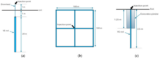
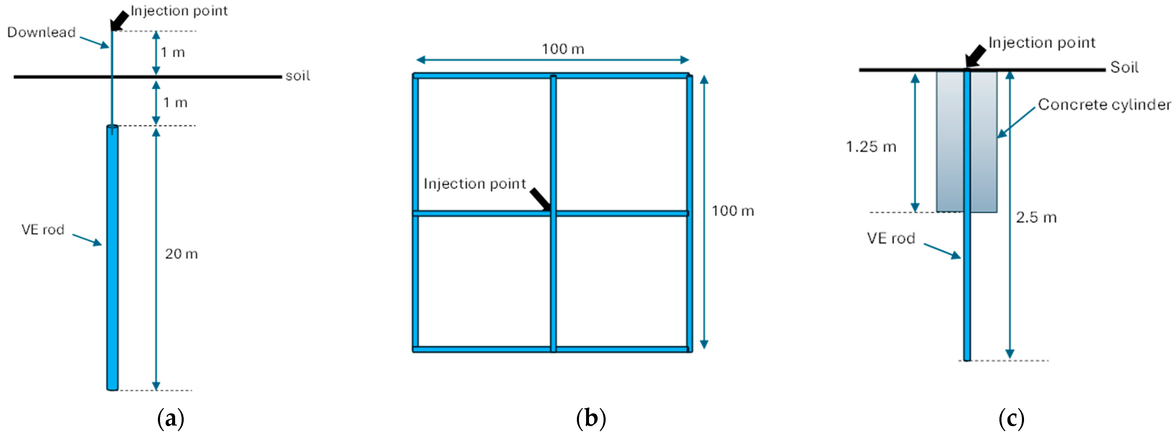
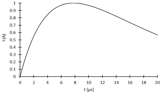
To validate and compare the temporal and frequency analyses implemented with Comsol Multiphysics, we decided to simulate three different grounding system arrangements; for these, most of the simulation parameters and results were available in the literature. The three (3) different grounding systems feature a single vertical copper rod (Figure 1a) and a uniform 100 × 100 m2 four-mesh grid (Figure 1b) obtained from [30], as well as a partially vertical rod encased in a concrete cylinder (Figure 1c) obtained from [25]. The first two grounding configurations were chosen as they represent simple and complex copper grounding systems, respectively. The third grounding configuration is the only configuration found in the literature that is similar to the ECON/GEC-EE grounding system proposed in this paper.
Figure 1.
Configuration of the grounding system used for validation with (a) a vertical copper rod, (b) a uniform 4-mesh copper grid, and (c) a partially vertical rod partially encased in concrete cylinder.
2.3.1. Vertical Copper Rod and Four-Mesh Copper Grid
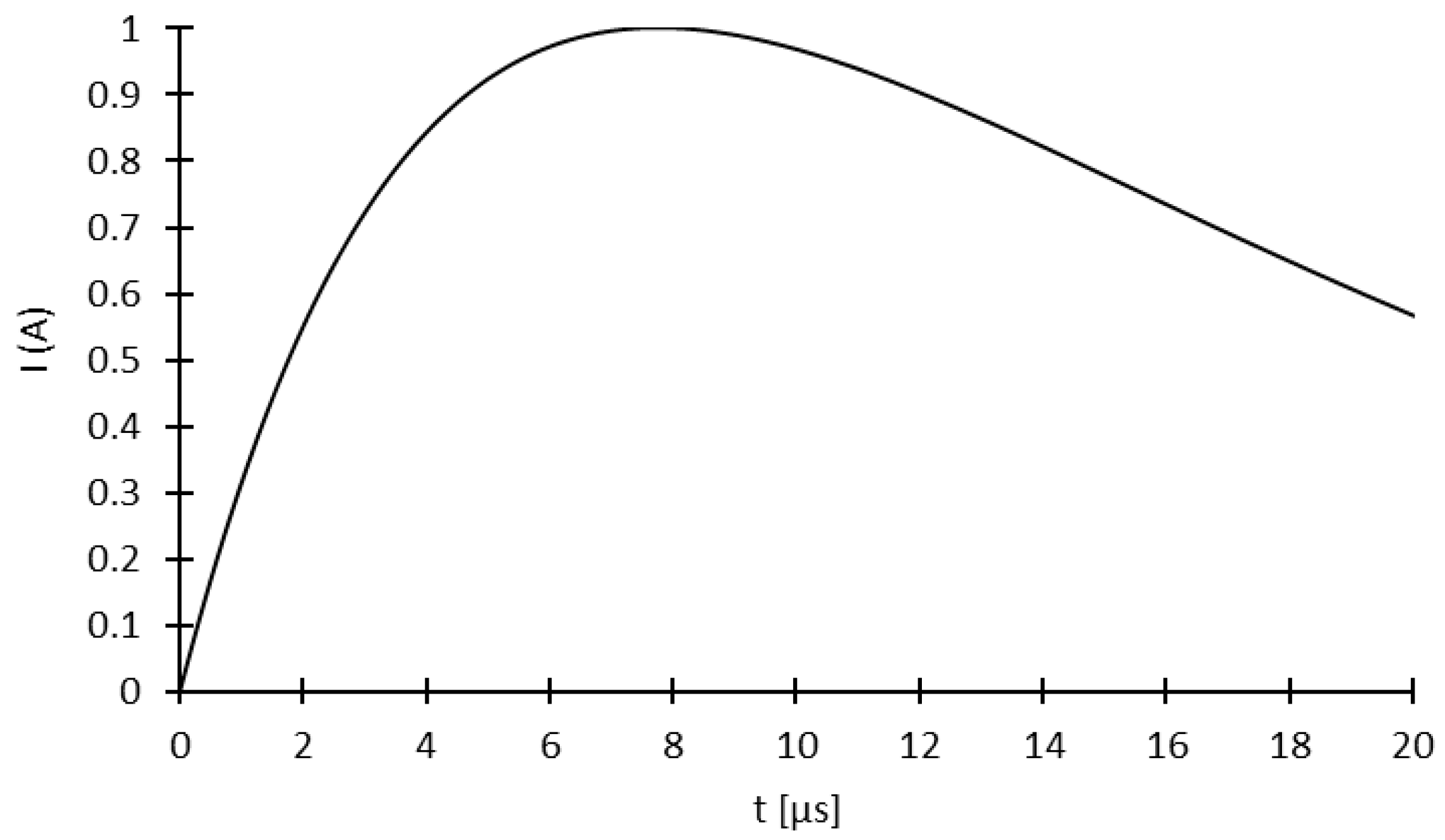
Figure 1a presents the geometry of a 20 m vertical copper rod buried at a uniform depth of 1 m into the soil [30]. Figure 1b presents a uniform four-mesh 100 × 100 m2 copper grid buried at 1 m depth in uniform soil [30]. Table 1 presents the principal simulation parameters used. The two models were originally simulated using the commercial software CDEGS for simulating complex grounding systems and electric networks [30]. This software is based on the finite element method (FEM) and uses a frequency domain analysis approach to solve transient problems [30]. To simulate the transient lightning current, the authors used an 8/20 µs biexponential 1 A peak current waveform (Figure 2) for the two grounding configurations; this was injected onto the top of a 2 m downlead for the vertical copper rod (Figure 1a) and in the middle of the four-mesh grid (Figure 1b). As information about the soil dimensions was not available, we decided to use soil dimensions equal to 1.5λ, where λ is the wavelength calculated with Equation (1). According to [31], such an assumption minimizes system reflection and therefore prevents absorbed boundaries from influencing the results. For both grounding configurations, simulations were carried out in both frequency and time domains with uniform soil (one layer).
Table 1.
Simulation parameters for vertical copper rod and 4-mesh copper grid [30].
Figure 2.
Bi-exponential waveform of the 8/20 µs with a peak current of 1 A.
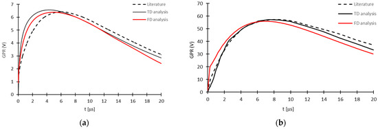
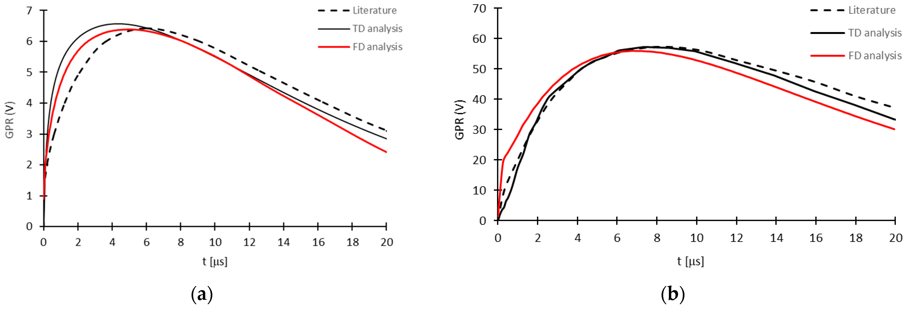
Frequency and temporal domain analysis validation were performed by comparing ground potential rise (GPR) results, as these depend not only on the injected current but also the grounding impedance [30]. Figure 3a,b present the comparative results obtained for the vertical copper rod and four-mesh grid, respectively. The GPR evolution extracted from [30] was obtained using the data extraction tool WebPlotDigitizer [33]. Table 2 presents a comparison of the maximum GPR value (GPRmax) obtained with TD and FD analyses and the results presented in the referenced paper.
Figure 3.
Comparison of the GPR evolutions obtained with TD and FD analyses for (a) a vertical copper rod and (b) a uniform 4-mesh grid.
Table 2.
Comparison of the maximum GPR obtained for the vertical copper rod and the uniform 4-mesh copper grid.
As a general observation, the results shown in Figure 3 demonstrate that the TD and FD analyses performed with the Comsol Multiphysics RF module present some small differences but remain very similar to the GPR obtained from the referenced paper. The GPR evolution obtained with TD analysis seems to be closer to the reference than that obtained with FD analysis. However, Table 2 shows that the discrepancy obtained for the maximum GPR value remains lower than 2.1% for the vertical rod and 2.3% for the four-mesh grid. It is also at this maximum GPR value that the grounding system’s impulse impedance is evaluated. The low discrepancy obtained hence demonstrates the validity of both analyses performed with the RF module, despite the assumption concerning soil dimensions for both.
2.3.2. Vertical Rod Partially Encased in Concrete Cylinder
This section presents the third grounding system arrangements used in the validation process, as presented in Figure 1c: a 2.5 m vertical copper electrode partially encased in a cylindrical concrete geometry of 1.25 m in length and 20 cm diameter [25]. The simulation parameters used by the authors are presented in Table 3.
Table 3.
Parameters of the vertical rod partially encased in concrete cylinder [25].
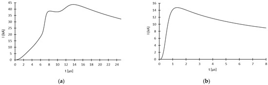
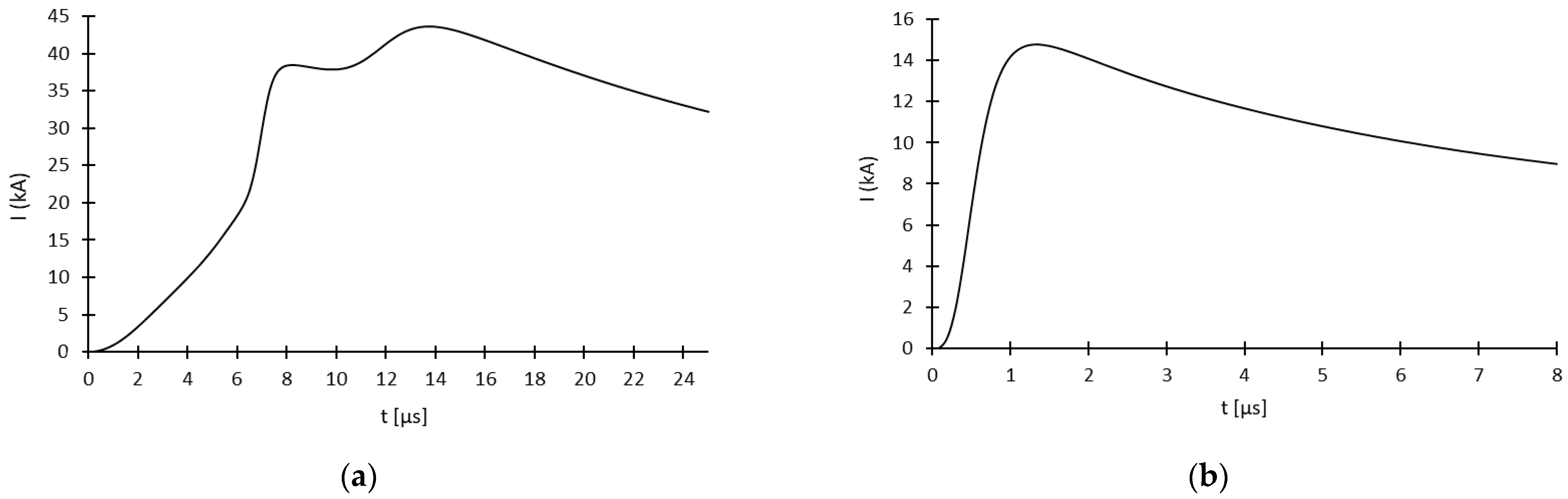
Two current lightning waveforms were used, drawn from Heidler lightning functions. Unlike bi-exponential functions, Heidler function is a unified function for the entire current waveform; consequently, it avoids the discontinuities found in simpler lightning current waveform models. Heidler function is largely employed in transient electromagnetic simulations and lightning protection design [25,30]. The first waveform (Figure 4a) corresponds to the first lightning stroke (14/45 μs) and the second (Figure 4b) to the subsequent stroke (1.4/140 μs) with faster current rise.
Figure 4.
Heidler lightning waveforms used for simulating (a) first (14/45 μs) and (b) subsequent lightning strokes (1.4/140 μs).
For the simulations, the authors used the Comsol Multiphysics AC/DC module with quasi-static approximation. Moreover, as the authors considered the frequency dependency of soil permittivity and resistivity, the simulations had to be carried out in the frequency domain. Models for these frequency dependencies are expressed by Equations (8) and (9), respectively, and are valid for a frequency range of 100 Hz to 4 MHz [25]:
where is the soil conductivity, is the low-frequency soil conductivity defined at 100 Hz, is the relative permittivity, is the relative permittivity at higher frequencies, is the vacuum permittivity, is a function describing the relative increase in soil conductivity as a function of low frequency conductivity , and is a constant related to the soil physical properties. The values given for , and are author-recommended values for obtaining mean results; the table of values can be found in [34].
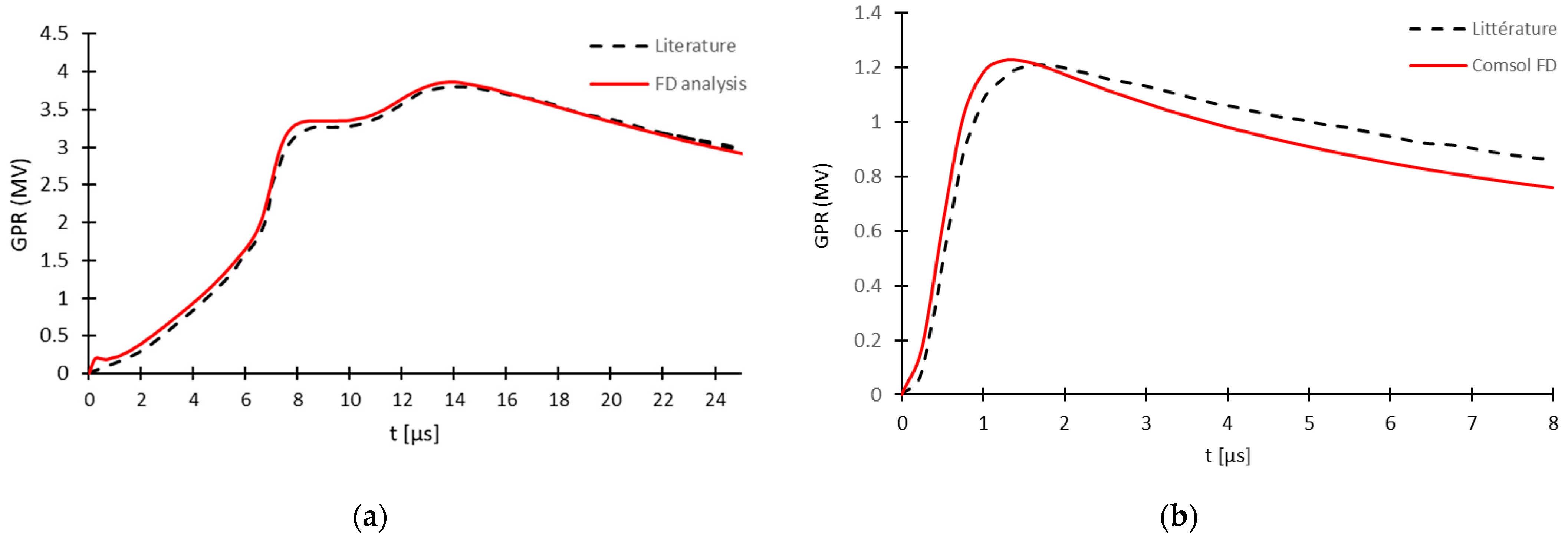
Figure 5a,b present a comparison between the GPR evolution obtained in the literature and the FD analysis for the first and subsequent strokes, respectively. The comparison was performed for a low-frequency soil conductivity of 3.33 mS/m. Table 4 presents a comparison of the peak impedance ZP obtained from the literature and FD analysis.
Figure 5.
Comparison of the GPR evolution obtained for a vertical copper electrode partially encased in a cylindrical concrete geometry buried in soil with a low-frequency soil conductivity σ0 of 3.33 mS/m for (a) first (14/45 μs) and (b) subsequent lightning strokes (1.4/140 μs).
Table 4.
Comparison of the discrepancy between the literature and FD analysis regarding the obtained peak impedance ZP.
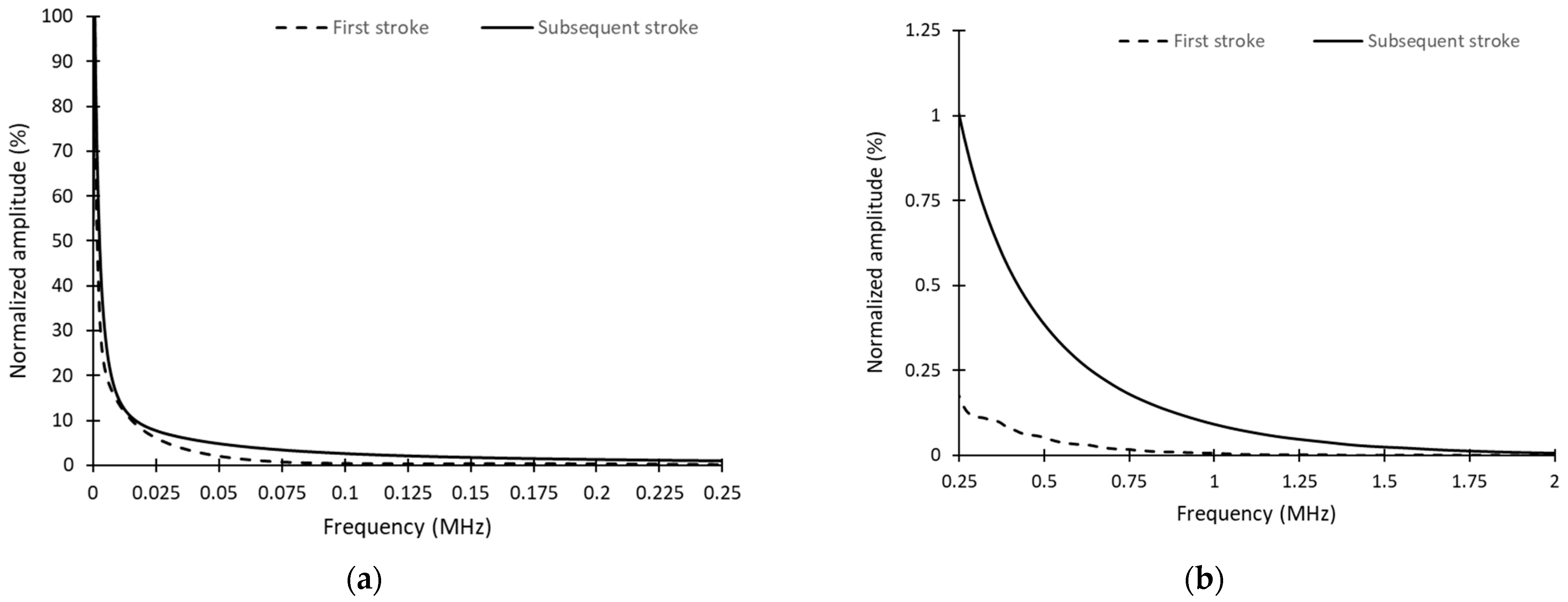
A comparison of the results shown in Figure 5 and Table 4 demonstrates the very good agreement between the simulation results obtained with FD analysis performed with the Comsol Mutiphysics RF module and the numerical results extracted from the literature. For the first lightning stroke, a very good accuracy is obtained in terms of GPR evolution (Figure 5a) and peak impedance (Table 4), with a discrepancy of 1.25%. For the subsequent lightning stroke, a difference in GPR evolution can be observed (Figure 5b) despite the 1.44% peak impedance discrepancy (Table 4). As the authors mentioned, they did not consider the propagation effect for high-frequency harmonics, as they performed all the simulations with the Comsol Multiphysics AC/DC module using quasi-static approximation. However, according to Equations (1) and (2), the limit of 0.1λ for a vertical rod partially encased in concrete cylinder is obtained around 0.9 MHz for a low-frequency soil conductivity of 3.33 mS/m. This means that for all the harmonics above 0.9 MHz, the propagation delay should normally be considered. Figure 6a,b present the distribution of the normalized amplitude of the harmonics for the two current waveforms shown in Figure 4. As the subsequent lightning stroke presents a faster rising time than the first, the amplitude of its high-frequency harmonics in the range of 0.9 to 2 MHz presents a higher amplitude than the first, as presented in Figure 6b. In this situation, the high frequency of the subsequent lightning stroke can have a more significant propagation effect; in turn, this can then affect the grounding system’s global response.
Figure 6.
Normalized amplitude distribution of the harmonics obtained for the first and subsequent lightning current waveforms for a frequency range between (a) 0 and 0.25 MHz and (b) 0.25 and 2 MHz.
3. The ECON/ECG-EE System’s Transient Lightning Response
3.1. Model Presentation
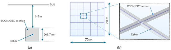
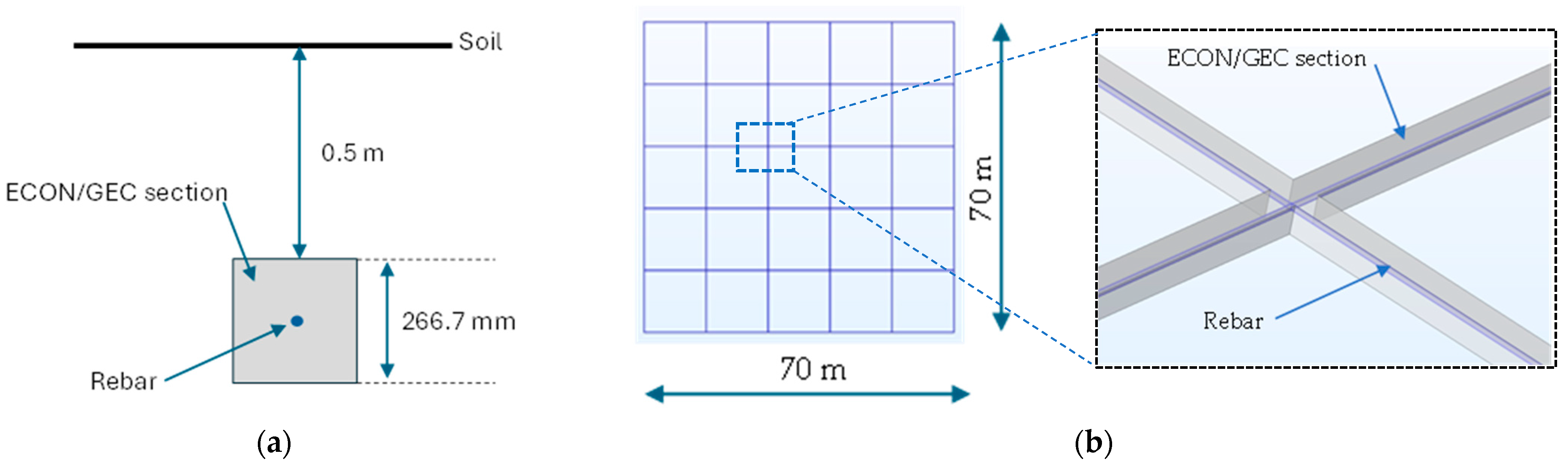
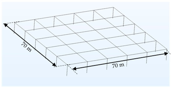
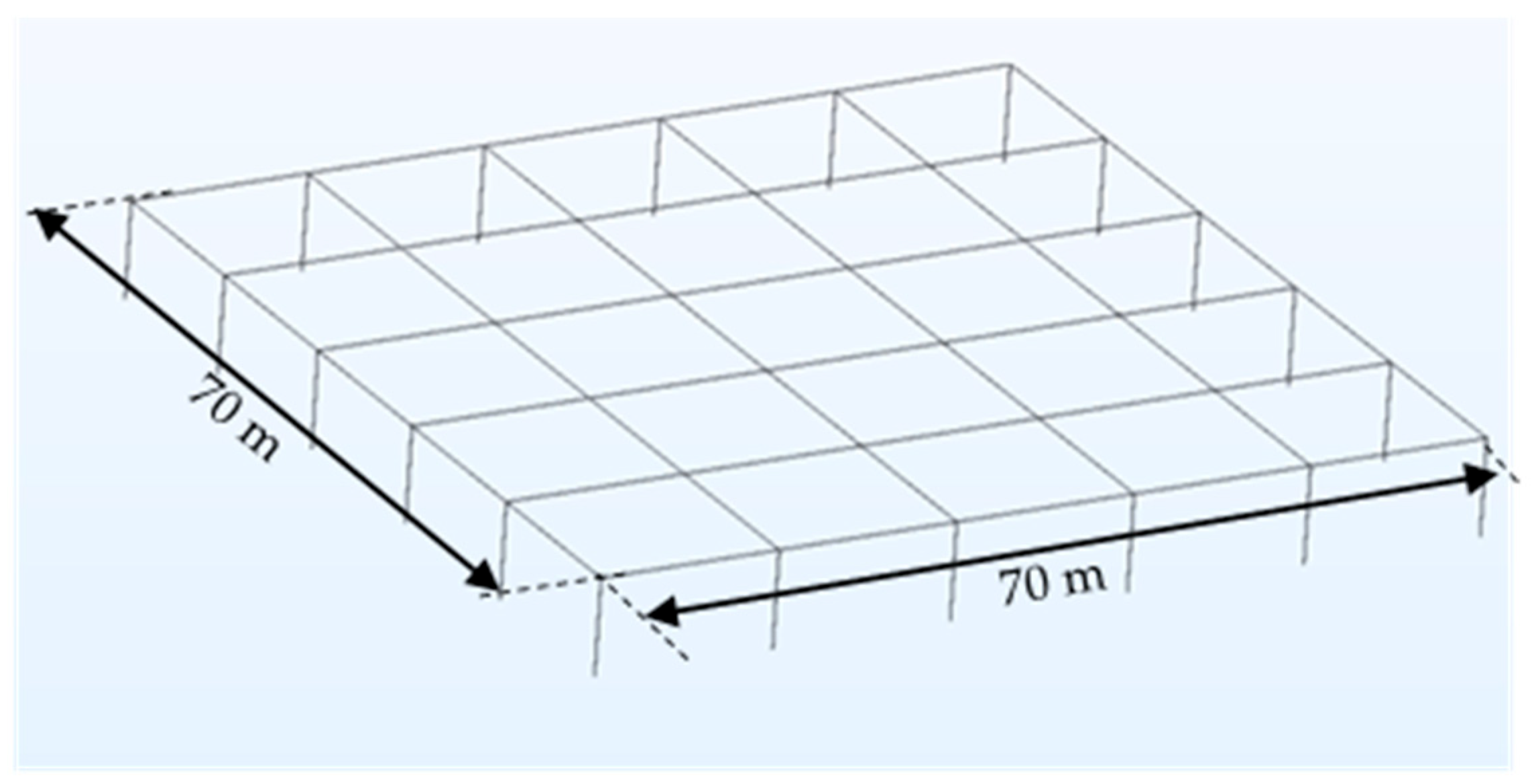
The FEM model of the ECON/ECG-EE system presented in Figure 7 is the same as that used in our previous study performed under stationary conditions [13]. With a resistivity of 5 Ω.m, the ECON/GEC forms a 266.7 mm square section inside, which is encased in the center the electrode (the rebar) with a 12.7 mm radius (Figure 7a). This ECON/ECG section length was chosen according to the results obtained in our previous study to obtain a grounding resistance RG of 1 Ω [13]. The center electrode is arranged in such a way as to form a 70 × 70 m2 square grid with a 25 mesh and 14 m spacing (Figure 7b).
Figure 7.
Presentation of the ECON/ECG-EE grounding system with (a) section and (b) overall views of the ECON/ECG-EE system.
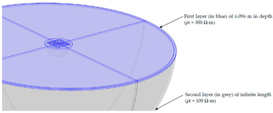
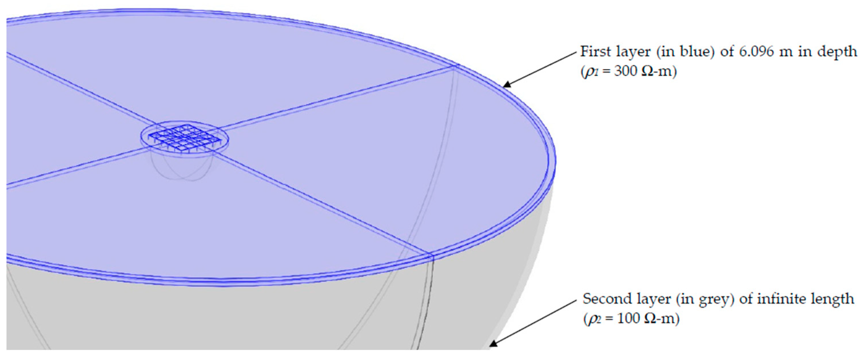
The grid is buried at a 0.5 m depth in two-layered soil, as presented in Figure 8. The first or upper layer of resistivity, ρ1 = 300 Ω.m, has a 6.096 m depth, while the second or infinite layer has ρ2 = 100 Ω.m. For both layers, the relative permittivity and permeability are and , respectively. All simulations were conducted with the Comsol Multiphysics RF module.
Figure 8.
General view of the FEM grounding model with two-layered soil.
To evaluate the behavior and efficiency of the ECON/EGC-EE grounding system under transient lightning current, the results were compared with those obtained with a conventional copper grid (Figure 9). This conventional grounding grid presents the same dimensions as the encased electrode of the ECON/EGC-EE grounding system (Figure 7b). It features a copper conductor radius of 9.27 mm and 20 vertical rods with a radius of 15.5 mm and a length of 7.5 m (Figure 9). As the conventional copper grid is buried at a 0.5 m depth in the same two-layer soil as the ECON/ECG-EE, the addition of the vertical rods was necessary to obtain a grounding resistance of 1 Ω in the stationary regime, as demonstrated in our previous study [13].
Figure 9.
General view of conventional copper grid with vertical rods.
3.2. Comparison of the Two Grounding Systems Using Time and Frequency Domain Analyses
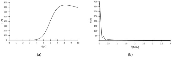
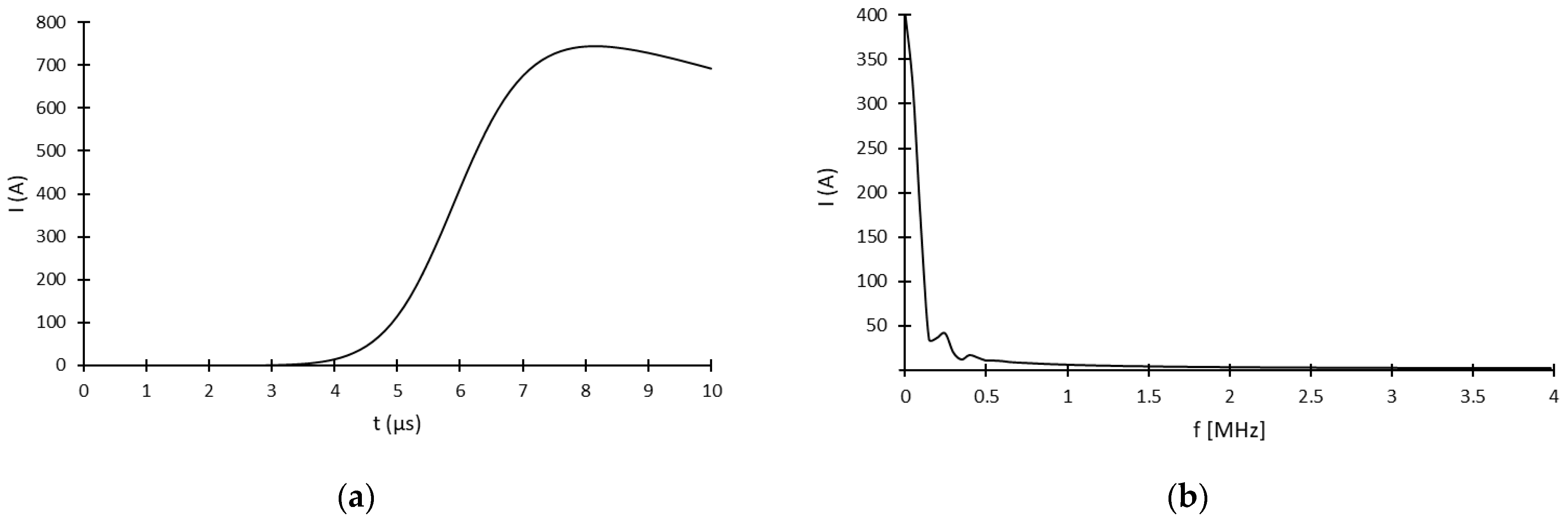
This section presents a comparison of the two grounding systems submitted to an 8/20 µs lightning current with a 744.8 A peak (Figure 10a). Due to its previously explained advantages, the Heidler function was used to model the lightning current impulse. A current peak value of 744.8 A was chosen in accordance with the stationary current value we employed in our previous study [13]. Simulations were performed in both TD and FD analyses. For the latter, an FFT of the 8/20 µs current impulse in a frequency range of up to 4 MHz was calculated (Figure 10b) using Comsol mathematical module global ODEs and DAEs.
Figure 10.
Representation of the 8/20 μs lightning current used for simulation in the (a) time and (b) frequency domains with the corresponding FFT.
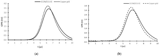
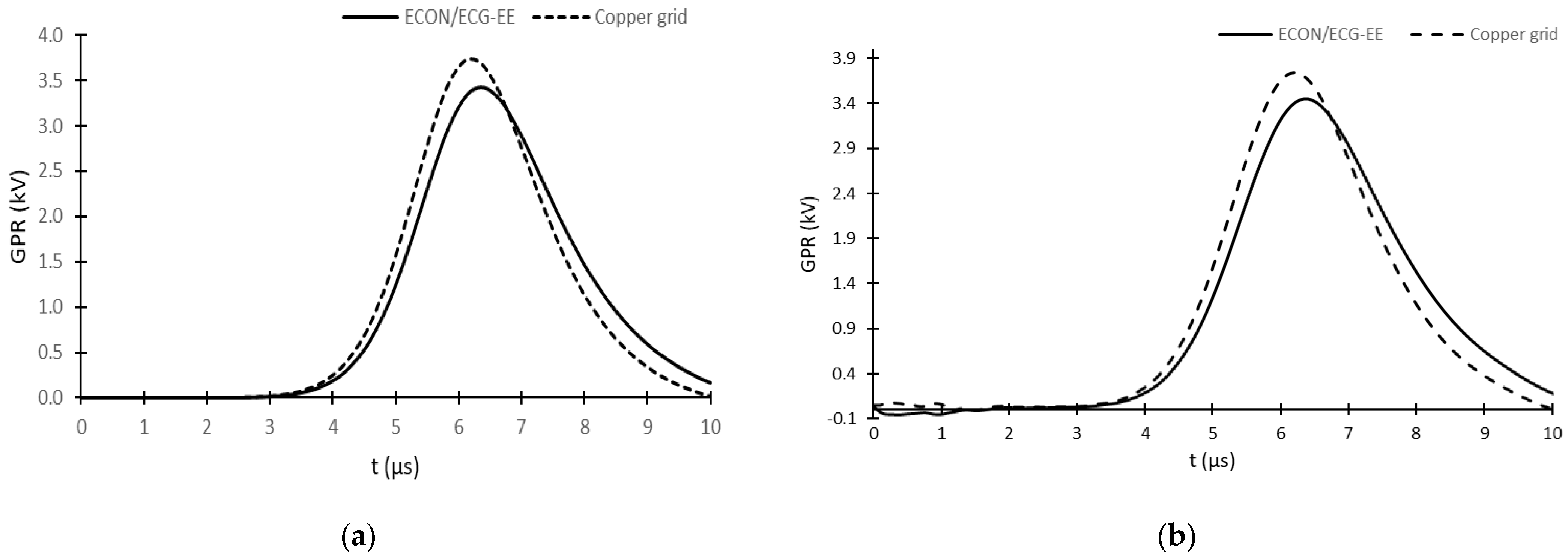
Figure 11a,b present the GPR obtained with the TD and FD analyses, respectively, where very good agreement between the two can be observed for both grounding systems. This agreement is confirmed by the results presented in Table 5, where peak impedance variations of only 0.87% and 0.20% are shown for the ECON/ECG-EE and copper grid, respectively. The results also demonstrate that the ECON/ECG-EE system seems to perform slightly better than the copper grid, with a reduction in ZP of 8.2%. This result is important considering that the copper grid used in the simulation is equipped with 20 vertical rods to achieve a grounding resistance RG of 1 Ω in a stationary regime [13]. This RG value can also be compared to the obtained peak impedance ZP, as shown in Table 5; this is around five times higher, demonstrating the importance of studying grounding system response under transient lightning current.
Figure 11.
Comparison of the GPR evolution of the ECON/ECG-EE system and conventional copper grid in response to an 8/20 μs lightning current for analyses performed in (a) time and (b) frequency domains.
Table 5.
Summary of time and frequency domain analyses.
Figure 11 also shows a difference in the GPR peak time, with 6.2 µs for the copper grid and 6.4 µs for the ECON/EGC-EE system. This means that the latter has a less inductive (or capacitive) effect than the former, which can be advantageous at high frequencies, as more capacitive effects tend to decrease the impedance [26].
4. Parameters Influencing the ECON/ECG-EE System Under Transient Lightning Response
This section presents a numerical investigation of the main parameters influencing ECON/ECG-EE system response under lightning current, the waveform of which was modeled using the Heidler function. These parameters are the ECON/ECG and soil resistivity, current waveform and soil conductivity, and soil relative permittivity frequency dependency. A performance comparison with the copper grid with vertical rods (Figure 9) was performed for all parameters except ECON/EGC resistivity. All simulations were conducted in the time domain, except for frequency-dispersive soil, for which frequency domain simulation is necessary.
4.1. Influence of ECON/ECG Electrical Resistivity
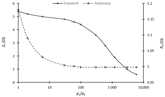
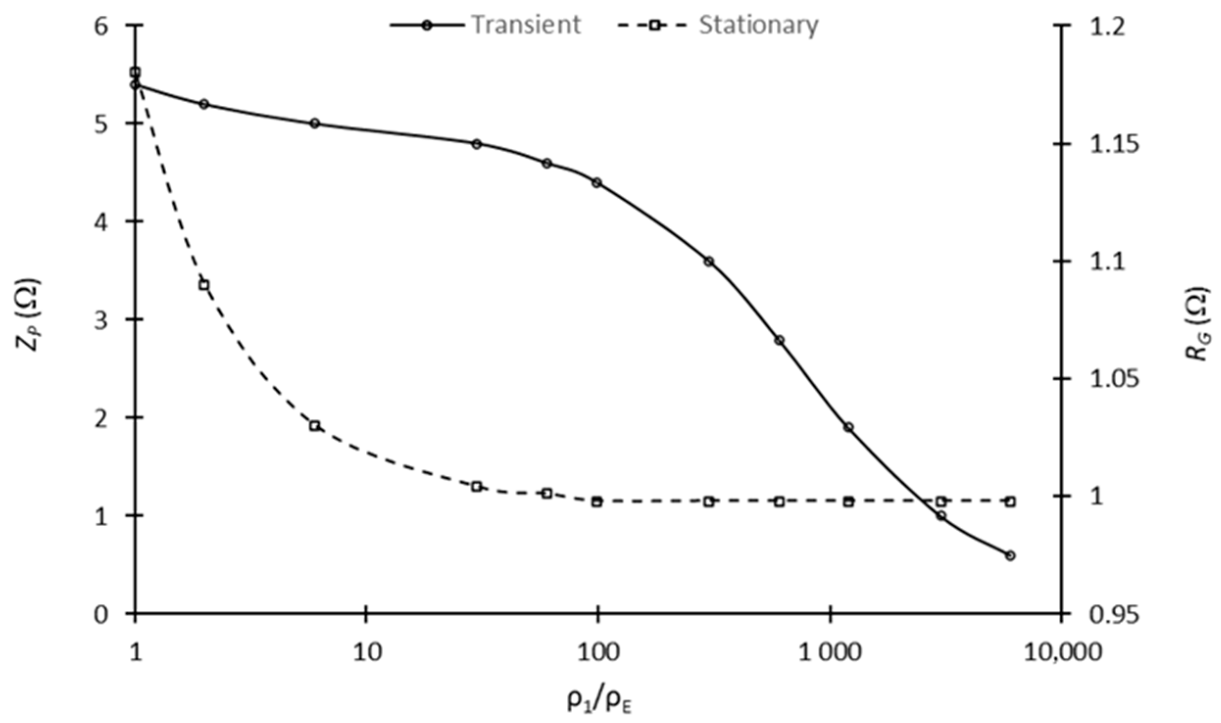
The influence of ECON/ECG resistivity ρE is investigated, with the same two-layer soil model shown in Figure 8, under a current impulse of 8/20 µs (Figure 10a). Table 6 presents the peak impedance ZP obtained as a function of ECON/EGC resistivity . Figure 12 shows the evolution of ZP as a function of the ratio, as well as the evolution of the steady-state grounding resistance RG calculated in stationary mode and presented in our previous study [13].
Table 6.
Influence of ECON/ECG resistivity on the peak impedance ZP and RG.
Figure 12.
Comparison of the ECON/ECG-EE system’s peak impedance ZP and grounding resistance RG evolutions as function of the ρ1/ρE ratio.
From the results obtained, comparing the ECON/ECG-EE system’s performance in steady-state and transient regimes reveals interesting peak impedance ZP and steady-state ground resistance RG behavior. Regarding the ratio ρ1/ρE of the soil resistivity (ρ1) divided by the ECON/ECG section resistivity (ρE), which ranges from 1 to 60, the ratio of ZP to RG is quite constant at an average of 4.7 with an approximately 15% decrease for both ZP and RG as ρ1/ρE increases. However, as the ratio ρ1/ρE increases from 60 to 6000 with the decrease in ρE, ZP continues to decrease significantly compared with RG, which remains quasi constant. As such, ZP reaches the value of RG for a ρ1/ρE ratio of 3000. This ratio, obtained for a soil resistivity of 100 Ω.m, corresponds to an ECON/ECG section resistivity (ρE) of 0.1 Ω.m, which represents a very high electrical conductivity value that is difficult to obtain for both electrically conductive concrete and geopolymer [17,18,35]. As ECON/ECG resistivities greater than 0.25 Ω.m are difficult to obtain, this means that the steady-state ground resistance RG can still be achieved under transient current pulse for a soil resistivity value ρ1 of 750 Ω.m, which falls between medium- and high-resistivity soil [3,4].
However, with the results presented in Table 6 and an ECON/ECG resistivity of 0.25 Ω.m, a ZP value of 1.9 Ω is obtained; this is 2.6 times lower than the peak impedance obtained with the copper grid equipped with vertical rods (Table 5) for the same soil conditions and current waveform. Hence, a comparison of the transient and steady-state mode results demonstrates that the ECON/ECG resistivity seems to have a more significant influence on the grounding system’s response to a transient lightning current. Moreover, whether under transient or stationary conditions, a ratio value of 60 appears to be a critical value to obtain.
4.2. Influence of Soil Resistivity
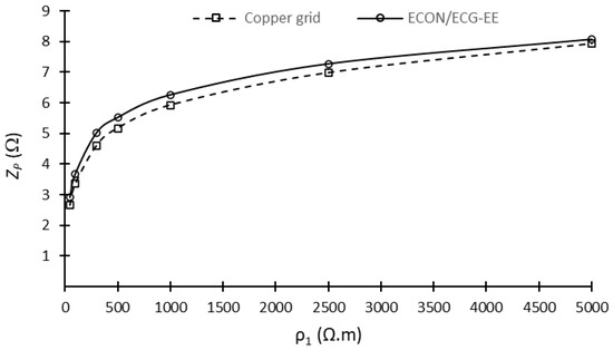
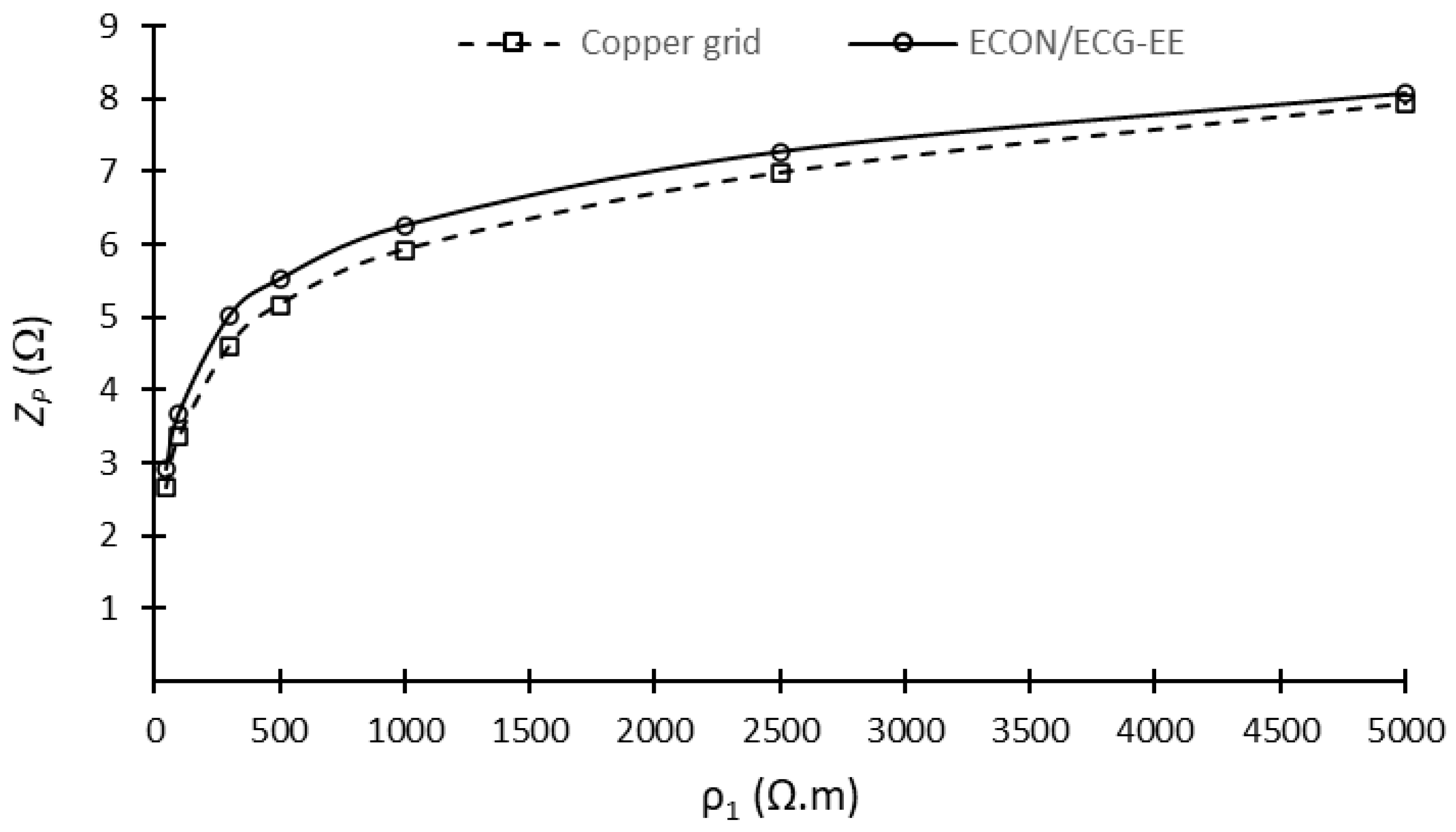
This section presents the influence of the upper soil layer resistivity (Figure 8) on the peak impedance ZP of both the ECON/ECG-EE grounding system (Figure 7) and the copper grid equipped with vertical rods (Figure 9), both under the same 8/20 μs lightning current waveform used in the previous section and presented in Figure 10. The ECON/ECG’s resistivity was kept constant and equal to 5 Ω-m. Table 7 presents a comparison of the peak impedance ZP value obtained for both the ECON/ECG-EE system and the copper grid, while Figure 13 shows the evolution of ZP as function of the first soil layer resistivity .
Table 7.
Grounding impedance as a function of upper layer soil resistivity.
Figure 13.
Comparison of peak impedance ZP evolution of both the copper grid with vertical rods and the ECON/EGC-EE system as a function of the first soil layer resistivity ρ1.
As a general observation, the ECON/ECG-EE system’s evolution presents better performance than the copper grid equipped with vertical rods, regardless of the soil resistivity. The two peak impedances ZP follow the same evolution as a function of soil resistivity. They are characterized by a rapid increase in ZP value until the soil resistivity reaches 500 Ω.m, after which the increase slows down significantly. The difference between the two grounding system peak impedances starts to increase when the soil resistivity increases from 50 to 300 Ω.m, with a higher difference obtained at 300 Ω.m. This last value corresponds to a ratio of 60, the specific value presented in the last section. From a soil resistivity of 500 Ω.m, the difference between the peak impedances of the two systems starts to decrease, reaching a lower value of 0.16 Ω at 5000 Ω.m. It is believed that the use of vertical rods for the copper grid, which reach the second layer with a resistivity of 100 Ω.m, helps maintain a relatively low increase rate in comparison with the ECON/ECG-EE system.
4.3. Influence of Lightning Current Waveform
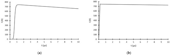
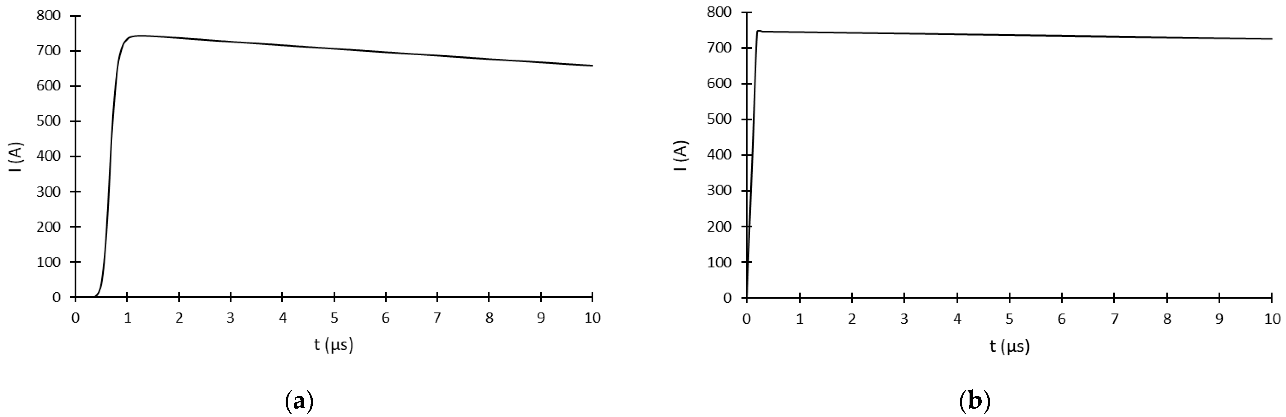
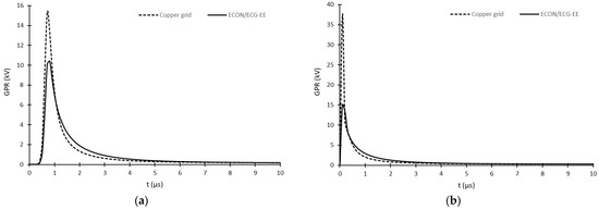
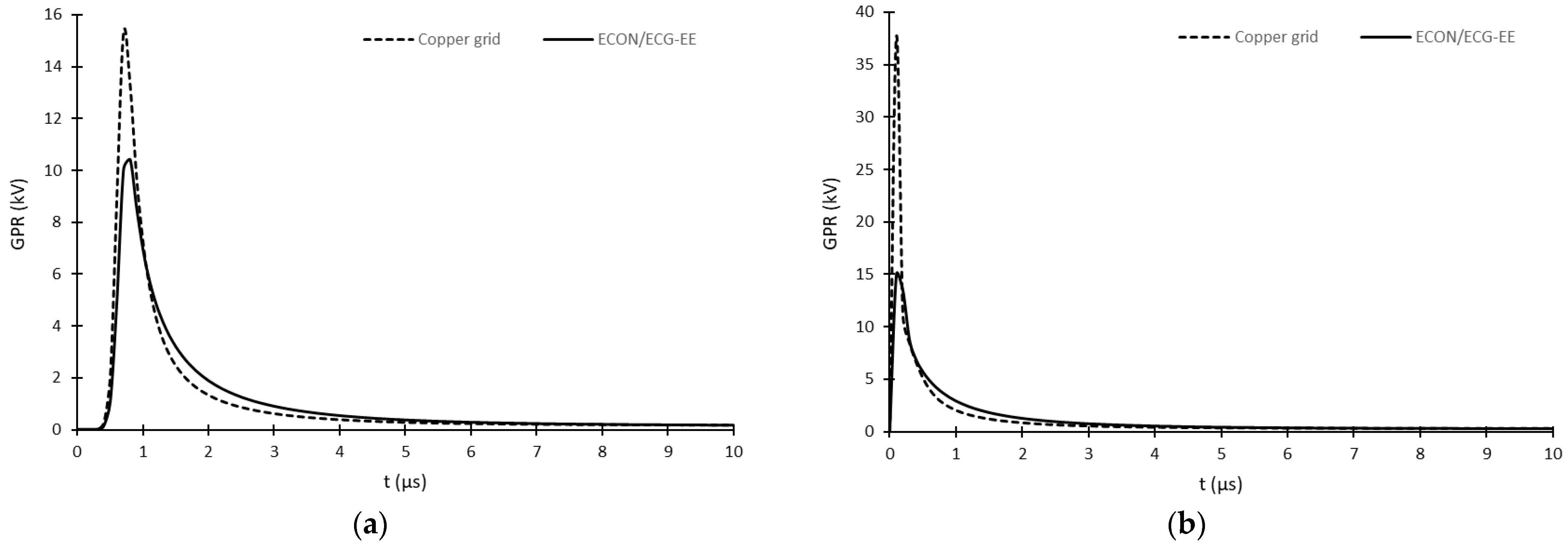
As experimentally and numerically reported in some studies, a grounding grid system’s response is significantly influenced by the current waveform used to model the current lightning impulse [26,36]. It has been reported that for the same peak current, it is principally the front-time which directly affects the peak impedance value ZP of the grounding system, with an increase in ZP as the front-time decreases [36,37]. Based on this interesting observation, we decided to compare the peak impedance ZP of both the ECON/EGEC-EE system (Figure 7) and copper grid with vertical rods (Figure 9) to three (3) different waveforms with the same peak current value of 744.8 A. The lightning current waveforms used are a conventional impulse of 8/20 µs, as used in previous sections (Figure 10a), and two faster current pulses at 1.2/50 µs (Figure 14a) and 0.24/350 µs (Figure 14b).
Figure 14.
Current waveforms with the same peak of 744.8 A modeled by (a) 1.2/50 µs and (b) 0.24/350 µs impulses.
A comparison of the GPR evolution obtained for the ECON/ECG-EE system and the copper grid with vertical rods is presented in Figure 11a and Figure 15a,b for 8/20 µs, 1.2/50 µs, and 0.24/350 µs current impulses, respectively. As a general observation, it is interesting to note that, for both grounding systems, the GPR peak value and, consequently, ZP increase significantly as the front-time current waveform decreases. These results agree with the experimental findings presented in [3,36,37,38,39]. However, as shown in Table 8, the peak impedance increase is less significant for the ECON/ECG-EE system than for the copper grid with vertical rods; indeed, ZP increases by a factor of 4.35 for the former versus 10.10 for the latter. Moreover, with increasing current waveform front-time, the difference between the peak impedance ZP of the two grounding systems increases drastically, with a significant advantage for the ECON/ECG-EE system, which presents a reduction of between 8.18% for an 8/20 µs current impulse and 60.41% for 0.24/350 µs. This behavior can be attributed to the frequency-dispersive characteristic of the ECON/EGC section compared with the soil surrounding the copper grid, as demonstrated in several studies performed on ground enhancement materials (GEMs) [40,41,42,43]. Nevertheless, all the results obtained demonstrate that under different front-time current waveforms, the ECON/EGC-EE system presents a better performance than a conventional copper grid.
Figure 15.
Comparison of the GPR obtained for both the copper grid with vertical rods and the ECON/ECG-EE system submitted to a lighting current with the same peak of 744.8 A and modeled by (a) 1.2/50 µs and (b) 0.24/350 µs impulses.
Table 8.
Influence of current waveform on the peak impedance ZP of both the ECON/ECG-EE system and the copper grid with vertical rods.
4.4. Influence of Frequency Dependence Soil Parameters
In this section, the ECON/ECG-EE’s grounding impedance is compared with that of the copper grid with vertical rods with soil presenting conductivity and relative permittivity frequency dependency. The two-layer soil model shown in Figure 8 was considered, where the conductivity and relative permittivity of each layer have a frequency dependency modeled using Equations (8) and (9), respectively. For comparison, the low frequency soil conductivity σ0 of each layer was equal to the values used in previous sections and the ratio was equal to 12, which is the relative permittivity value also used previously. The simulations were performed in the frequency domain using a lightning current pulse of 8/20 µs (Figure 10).
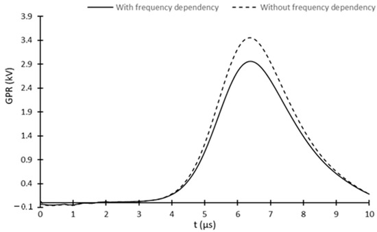
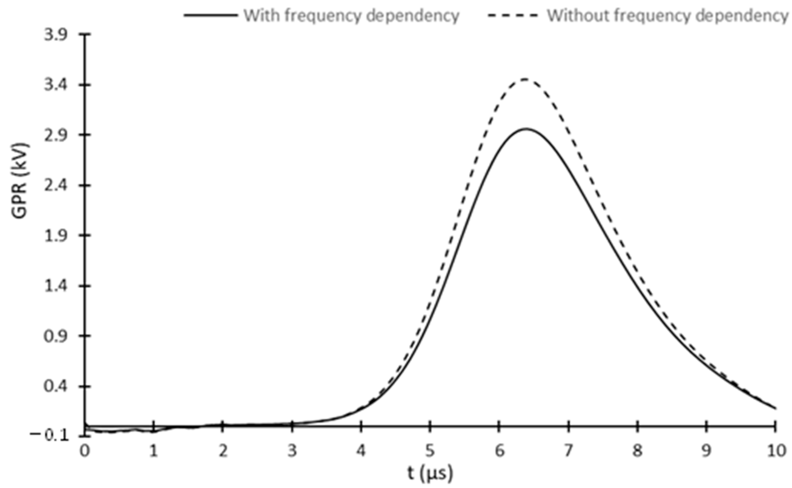
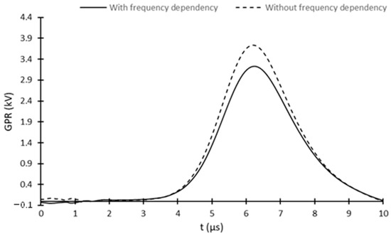
Figure 16 and Figure 17 compare the GPR evolutions obtained with and without the two-layer frequency-dispersive soil model for the ECON/ECG-EE system and the copper grip with vertical rods, respectively. Table 9 compares the peak impedance ZP for the two grounding systems with and without the two-layer frequency-dispersive soil model. For the two grounding systems, it can be observed that GRP and peak impedance ZP are lower when the soil parameters’ frequency dependances are considered. Indeed, ZP reductions (Table 9) of 14.22% and 13.55% are obtained for the ECON/ECG-EE system and copper grid, respectively. The results obtained are consistent with those presented in different studies in the literature, where similar peak impedance reductions were observed [25,34,38,39].
Figure 16.
Comparison of the ECON/ECG-EE system’s GPR evolution with and without the two-layer frequency dispersive soil model.
Figure 17.
Comparison of the copper grid’s GPR evolution with and without the two-layer frequency dispersive soil model.
Table 9.
Comparison of the peak impedance ZP of the ECON/ECG-EE system and the copper grid with vertical rods obtained with and without the two-layer frequency dispersive soil model.
5. Conclusions
In this paper, we numerically investigated a new grounding system, ECON/ECG-EE, with interesting potential to replace conventional copper grids in HV substation applications. First, this study demonstrated that complex and large grounding systems submitted to different lightning current impulses can be simulated using the Comsol Multiphysics FEM software’s RF module with both temporal and frequency domain analyses. These two analyses allow us to consider the wave propagation phenomenon. Furthermore, they have demonstrated very good accuracy compared with different grounding systems presented in the literature with a maximum 5.13% deviation. Moreover, good agreement was also obtained when frequency-dependent soil parameters were considered, demonstrating the versatility of the general FEM software used in our study. Validating the temporal and frequency domain approaches has also highlighted the importance of considering the wave propagation phenomenon at higher frequencies when the current impulse waveform rise-time decreases.
After validation, we investigated the ECON/ECG-EE grounding system’s performance in transient and high-frequency conditions, comparing it with a conventional copper grounding system equipped with vertical rods to achieve a low-frequency ground resistance of 1 Ω for the two-layer soil model used. As a general observation, the results obtained show that the ECON/ECG-EE system has a better overall performance under different soil resistivities and current waveforms. More specifically, our results show that the ECON/ECG-EE system’s peak impedance ZP is always lower than that of the copper grid, between 2.0% and 8.2% depending on the soil resistivity. Moreover, as the transient current waveform front-time decreases, as with faster lightning strokes, the ECON/ECG-EE system demonstrates significantly better performance than the copper grid system, with peak impedance ZP reductions of 31.9% and 60.4% for a current pulse of 1.2/50 µs and 0.24/350 µs, respectively, compared to 8.2% for 8/20 µs. Practically, these results reveal that the ECON/ECG-EE system can provide significant advantages compared to conventional grounding copper grid when the soil resistivity increases or when the front-time of the lightning current pulse is small.
Comparing the ECON/ECG-EE system’s performance between stationary or transient regime reveals an interesting peak impedance ZP and stationary ground resistance RG behavior. In particular, for both steady-state and transient regimes, the ρ1/ρE ratio of the soil resistivity (ρ1) divided by a ECON/ECG section resistivity (ρE) of 60 seems to be the minimum value required for satisfactory grounding system behavior, despite a ZP value that is 4.6 times greater than RG. Above this minimum value of 60, the peak impedance ZP decreases rapidly compared to the grounding resistance RG, which remains constant. These results are valid for medium-resistivity soil. As soil resistivity increases, the peak impedance for both the ECON/ECG-EE system and the copper grid with vertical rods increases in the same manner, but with a consistently lower ZP value for the former. This result confirms that the proposed ECON/ECG-EE system presents a considerable advantage over conventional copper grid system for medium to high soil resistivities, either under steady-state conditions or transient lightning currents.
The results presented in this paper are general; they can be used for grounding systems in which the electrode is encased in electrically conductive concrete (ECON) or electrically conductive geopolymer (ECG). In our laboratories, researchers are currently developing GEC formulations based on bauxite residues (red mud). One of their research avenues involves studying GEC electrical conductivity frequency dependence to improve the numerical models presented in this article. The experimental results of this study will be useful for improving the EGC-EE system’s prediction of lightning impulses and high-frequency fault currents. In addition to the frequency-dispersive model, a numerical investigation will be conducted to determine the influence of soil ionization and high-magnitude fault currents on the proposed system. Finally, the steady-state grid resistance evolution of a small-scale ECON-EE system as a function of seasonal influences is currently under experimental investigation, along with its response to transient lightning currents. The results obtained from these studies and presented in future papers will also permit us to validate the numerical transient models and results presented in this paper.
Author Contributions
Conceptualization, C.V.; methodology, A.S.; software, A.S. and C.V.; validation, A.S. and C.V.; writing—original draft preparation, A.S. and C.V.; writing—review and editing, R.J.A., G.S. and C.V.; supervision, C.V., R.J.A. and G.S.; project administration, R.J.A.; funding acquisition, R.J.A. and C.V. All authors have read and agreed to the published version of the manuscript.
Funding
This research was funded by Rio Tinto in partnership with the Mitacs Accelerate program, under grant number FR138199.
Data Availability Statement
The data presented in this study are available on request from the corresponding author. The data are not publicly available due to privacy concerns.
Conflicts of Interest
The authors declare no conflicts of interest.
References
- Abdul Ali, A.W.; Ahmad, N.N.; Mohamad Nor, N.; Idris, N.F.; Hanaffi, F. Investigations on the Performance of Grounding Device with Spike Rods (GDSR) with the Effects of Soil Resistivity and Configurations. Energies 2020, 13, 3538. [Google Scholar] [CrossRef] [Scilit]
- Lee, H.S.; Kim, J.H.; Dawalibi, F.P.; Ma, J. Efficient ground grid designs in layered soils. IEEE Trans. Power Deliv. 1998, 13, 745–751. [Google Scholar] [CrossRef] [Scilit]
- Permal, N.; Osman, M.; Kadir, M.Z.A.A.; Ariffin, A.M. Review of substation grounding system behavior under high frequency and transient faults in uniform soil. IEEE Access 2020, 8, 142468–142482. [Google Scholar] [CrossRef] [Scilit]
- 80-2013; IEEE Guide for Safety in AC Substation Grounding. IEEE: New York, NY, USA, 2015; pp. 1–226.
- Market Research Future (MRFR). Substation Grounding System Market, ID MRFR/EnP/24666-HCR. 2025. Available online: https://www.marketresearchfuture.com/reports/substation-grounding-system-market-26317 (accessed on 17 December 2025).
- Boateng, F.G.; Klopp, J.M. The electric vehicle transition: A blessing or a curse for improving extractive industries and mineral supply chains? Energy Res. Soc. Sci. 2024, 113, 103541. [Google Scholar] [CrossRef] [Scilit]
- Li, Y.; Zhang, C.; Liu, S.; Wang, P. Research on the Application of New Hot Cast Copper Clad Steel Composite Metal Material in Substation Grounding System. J. Electr. Eng. 2021, 16, 77–82. [Google Scholar]
- Wen, X.; Song, Z.; Tan, B.; Yang, J.; Gao, C.; Wang, L. Electrical properties of copper-clad steel grounding conductors. High Volt. Eng. 2015, 41, 345–348. [Google Scholar]
- Al-Khayari, H.A.; Mallela, V.S.; Tanavade, S. Design of sub-station grounding system—A case study at PDO, and MZEC, Sultanate of Oman. In Proceedings of the International Conference on Electrical and Computing Technologies and Applications (ICECTA), Ras Al Khaimah, United Arab Emirates, 21–23 November 2017. [Google Scholar]
- Ahmad, H.; Sidik, M.A.B.; Lau, K.Y. Anti-theft Grounding System for Industrial Application. Int. Rev. Electr. Eng. 2010, 5, 1271–1276. [Google Scholar]
- Ahmad, A.; Saroni, M.R.A.; Razak, I.A.W.A.; Ahmad, S. A case study on ground resistance based on copper electrode vs. galvanized iron electrode. In Proceedings of the IEEE International Conference on Power and Energy (PECON), Kuching, Malaysia, 1–3 December 2014. [Google Scholar]
- Bakar, O.A.; Arshad, S.N.M.; Ariffen, A.M.; Halim, N.H.; Leong, W.C.; Romli, M.I.F.; Hasni, N.A.S. Performance of Galvanized–Steel and Copper Grounding Electrodes Using Bentonite and Coconut Husk Ashes as an Additives Material to Grounding System. Mater. Sci. Eng. 2020, 864, 012185. [Google Scholar]
- Daadaa, M.; Brettschneider, S.; Volat, C.; Simard, G. Numerical Investigation of the Use of Electrically Conductive Concrete-Encased Electrodes as Potential Replacement for Substation Grounding Systems. Energies 2023, 16, 4410. [Google Scholar] [CrossRef] [Scilit]
- Daadaa, M.; Brettschneider, S.; Volat, C.; Savar, V. Improving substation grounding performance in cold climate regions using new method based on electrically conductive concrete encased electrodes (ECON-EE). In Proceedings of the CIGRE Canada Conference and Exhibition, Vancouver, BC, Canada, 25–28 September 2023. [Google Scholar]
- Ufer, H.G. Investigation and Testing of Footing-Type Grounding Electrodes for Electrical Installations. IEEE Trans. Power Appar. Syst. 1964, 83, 1042–1048. [Google Scholar] [CrossRef] [Scilit]
- Bungau, C.C.; Bungau, T.; Prada, I.F.; Prada, M.F. Green buildings as a necessity for sustainable environment development: Dilemmas and challenges. Sustainability 2022, 14, 13121. [Google Scholar] [CrossRef] [Scilit]
- Payakaniti, P.; Pinitsoontorn, S.; Thongbai, P.; Amornkitbamrung, V.; Chindaprasirt, P. Electrical conductivity and compressive strength of carbon fiber reinforced fly ash geopolymeric composites. Constr. Build. Mater. 2017, 135, 164–176. [Google Scholar] [CrossRef] [Scilit]
- Chen, J.; Lu, W.; Weng, D.; Li, Y.; Guo, C. Preparation and Conductivity Study of Doped Graphite Based Geopolymers. SSRN 2024. [Google Scholar] [CrossRef] [Scilit]
- Davidovits, J. Geopolymer Chemistry and Applications, 5th ed.; Geopolymer Institute: Saint-Quentin, France, 2008. [Google Scholar]
- Kumar, S.G.K.M.; Kinuthia, J.M.; Oti, J.; Adeleke, B.O. Geopolymer Chemistry and Composition: A Comprehensive Review of Synthesis, Reaction Mechanisms, and Material Properties—Oriented with Sustainable Construction. Materials 2025, 18, 3823. [Google Scholar] [CrossRef] [Scilit]
- Silveira, N.C.; Martins, M.L.; Bezerra, A.C.; Araújo, F.G. Red mud from the aluminium industry: Production, characteristics, and alternative applications in construction materials—A review. Sustainability 2021, 13, 12741. [Google Scholar] [CrossRef] [Scilit]
- Li, Y.; Min, X.; Ke, Y.; Liu, D.; Tang, C. Preparation of red mud-based geopolymer materials from MSWI fly ash and red mud by mechanical activation. Waste Manag. 2019, 83, 202–208. [Google Scholar] [CrossRef] [Scilit]
- Fagan, E.J.; Lee, R.H. The Use of Concrete-Enclosed Reinforcing Rods as Grounding Electrodes. IEEE Trans. Ind. Gen. Appl. 1970, 6, 337–348. [Google Scholar] [CrossRef] [Scilit]
- Cabral, R.J.; Gazzana, D.S.; Tronchoni, A.B.; Dias, G.A.D.; Leborgne, R.C.; Bretas, A.S.; Tello, M. Comparative performance of impulsive grounding systems embedded in concrete: An experiment in reduced scale. In Proceedings of the 33rd International Conference on Lightning Protection (ICLP), Estoril, Portugal, 25–30 September 2016. [Google Scholar]
- Bezerra, G.V.N.; Moreira, F.A.; Ferreira, T.V.; Alipio, R. Concrete Encased Grounding: Lightning Response Analysis Considering the Frequency Dependence of Soil. IEEE Trans. Electromagn. Compat. 2024, 66, 879–889. [Google Scholar] [CrossRef] [Scilit]
- Visacro, S. A comprehensive approach to the grounding response to lightning currents. IEEE Trans. Power Deliv. 2006, 22, 381–386. [Google Scholar] [CrossRef] [Scilit]
- Wu, J.; Zhang, B.; He, J.; Zeng, R. A comprehensive approach for transient performance of grounding system in the time domain. IEEE Trans. Electromagn. Compat. 2014, 57, 250–256. [Google Scholar] [CrossRef] [Scilit]
- Theethayi, N.; Thottappillil, R.; Paolone, M.; Nucci, C.A.; Rachidi, F. External Impedance and Admittance of Buried Horizontal Wires for Transient Studies using Transmission Line Analysis. IEEE Trans. Dielectr. Electr. Insul. 2007, 14, 751–761. [Google Scholar] [CrossRef] [Scilit]
- Nguyen, X.B.; Nguyen, N.N.; Le, T.M.T.; Vu, P.T. The RBF-FDTD Method for Computing Lightning-Transient Voltages on Grounding Systems. IEEE Access 2025, 13, 97487–97498. [Google Scholar] [CrossRef] [Scilit]
- Zedan, B. Characterisation of Substation Earth Grid Under High Frequency and Transient Conditions. Ph.D. Thesis, University of Wales, Cardiff, UK, 2005. [Google Scholar]
- Frei, W. Computational Electromagnetics Modeling: Which Module to Use? 2020. Available online: https://www.comsol.com/blogs/computational-electromagnetics-modeling-which-module-to-use (accessed on 28 June 2025).
- Comsol. RF Module User’s Guide; Comsol: Burlington, MA, USA, 2018. [Google Scholar]
- WebPlotDigitizer. Available online: https://www.automeris.io (accessed on 22 September 2025).
- Vujević, S.; Lovrić, D. Exponential approximation of the Heidler function for the reproduction of lightning current waveshapes. Electr. Power Syst. Res. 2010, 80, 1293–1298. [Google Scholar] [CrossRef] [Scilit]
- Chung, D.D.L. Electrically conductive cement-based materials. Adv. Cem. Res. 2004, 16, 167–176. [Google Scholar] [CrossRef]
- Visacro, S.; Alipio, R. Frequency Dependence of Soil Parameters: Experimental Results, Predicting Formula and Influence on the Lightning Response of Grounding Electrodes. IEEE Trans. Power Deliv. 2012, 27, 927–935. [Google Scholar] [CrossRef] [Scilit]
- Visacro, S.; Guimarães, M.B.; Araujo, L.S. Experimental impulse response of grounding grids. Electr. Power Syst. Res. 2013, 94, 92–98. [Google Scholar] [CrossRef] [Scilit]
- Araujo, L.; Castro, R.V.; Santos, L.F.D.; Vale, M.M.; Visacro, S. Impulse response of grounding grids: Experimental versus simulated results. In Proceedings of the 14th International Conference on Lightning Protection (ICLP), Vienna, Austria, 2–7 September 2012. [Google Scholar]
- Cavka, D.; Mora, N.; Rachidi, F. A Comparison of Frequency-Dependent Soil Models: Application to the Analysis of Grounding Systems. IEEE Trans. Electromagn. Compat. 2014, 56, 177–187. [Google Scholar] [CrossRef] [Scilit]
- Moradi, M. Analysis of transient performance of grounding system considering frequency-dependent soil parameters and ionization. IEEE Trans. Electromagn. Compat. 2019, 62, 785–797. [Google Scholar] [CrossRef] [Scilit]
- Muhammad, U.; Ahmad, N.N.; Nor, N.M.; Aman, F. Effect of Enhancement Material on the Performance of Ground Electrodes under Impulse Conditions. IEEE Access 2025, 13, 106296–106310. [Google Scholar] [CrossRef] [Scilit]
- Androvitsaneas, V.P.; Gonos, I.F.; Stathopulos, I.A. Experimental study on transient impedance of grounding rods encased in ground enhancing compounds. Electr. Power Syst. Res. 2016, 139, 109–115. [Google Scholar] [CrossRef] [Scilit]
- Ahmad, W.W.; Rahman, M.A.; Jasni, J.; Ab Kadir, M.Z.A.; Hizam, H. Chemical enhancement materials for grounding purposes. In Proceedings of the International Conference on Lightning Protection (ICLP), Cagliari, Italy, 13–17 September 2010. [Google Scholar]

Disclaimer/Publisher’s Note: The statements, opinions and data contained in all publications are solely those of the individual author(s) and contributor(s) and not of MDPI and/or the editor(s). MDPI and/or the editor(s) disclaim responsibility for any injury to people or property resulting from any ideas, methods, instructions or products referred to in the content. |
© 2026 by the authors. Licensee MDPI, Basel, Switzerland. This article is an open access article distributed under the terms and conditions of the Creative Commons Attribution (CC BY) license.