


Featured Application
(1) Framework of an online support system for nuclear power plant accident management. (2) Method of online simulation for a nuclear power plant. (3) Logic of data interaction and operation control. (4) Solution for visualization of accident critical parameters and information.
Abstract
Compared to other energy sources, nuclear power plants (NPPs) can provide clean and reliable electricity with relatively low operating costs. The NPPs are also associated with severe accidents, which are extremely rare. But once they occur, they put immense pressure on the accident management team and may cause great social and environmental impact. In this paper, we report on the ongoing development of an online support system for NPP accident management. This system combined accident diagnosis and online simulation to assess the damage state of NPP, predict possible accident progressions, and evaluate the available actions and their consequences. The system can be equipped in the Technical Support Center (TSC) or the emergency command center (ECC), which can effectively use the data from NPP and communicate with the main control room MCR and other staff immediately.
1. Introduction
In 2011, the Fukushima-Daiichi nuclear accident shocked the world once again. The earthquake and subsequent tsunami led to failures of both alternating current (AC) and direct current (DC) power supplies, resulting in the loss of all safety functions at the nuclear power plant (NPP). Neither the emergency operating procedures (EOPs) nor the severe accident management guidance (SAMG) succeeded in protecting the reactor core and containment structure [1]. The Fukushima accident highlighted the importance of gaining an in-depth understanding of such accident sequences and developing or enhancing robust severe accident management (SAM) measures to ensure the safety of NPPs in the future.
To address the challenges of severe accident management, a number of Accident Management Support Systems (AMSSs) have been proposed, evolving from early parameter tracking to complex decision support. These systems can generally be categorized based on their functional focus and underlying methodologies. Early pioneering efforts, such as MARS [2] and ERSS [3], focused on establishing the fundamental architecture for monitoring and basic response planning. Subsequent developments emphasized the accurate identification of plant states. Systems like CAMS [4,5] and ADAM [6,7] integrated advanced diagnostic logic. This trend continued with knowledge-driven frameworks such as RISARD [8], SAMEX [9], and the smart support system for diagnosing severe accidents in nuclear power plants (NPPs) [10], which leveraged expert rules to interpret complex accident progressions. More recently, efforts have shifted towards holistic integration. ADAPT [11] and NARSIS [12] represent the state of the art in combining multiple data streams for comprehensive management. While these AMSSs have significantly advanced the field, they are predominantly based on a single paradigm or a specific combination of model-driven and knowledge-driven frameworks. Most existing solutions lack a detailed mission profile analysis and a universal, extensible integration framework capable of supporting the “Digital Twin” concept in real-time. Consequently, there remains a need for a system that seamlessly integrates online simulation with dynamic diagnosis to support the full lifecycle of accident management. Accident management in NPPs is a complex and dynamic process, and it is impossible for any decision support system to fully automate the problem-solving workflow. In other words, human intervention remains indispensable for resolving specific issues that cannot be addressed by automated systems alone. However, most existing AMSSs lack a dynamic alignment with the specific mission profiles of different accident stages, which limits their ability to provide phase-specific operational support.
Drawing on lessons learned from the Fukushima nuclear accident, international organizations and institutions further clarified that the accident management support tools are in urgent need of adaptability research in extremely complex accident scenarios to provide continuous and comprehensive technical support for accident management [13]. Specifically, there is an imperative to rethink the philosophy underpinning NPP accident management; integrate the technical support of EOP, SAMG, and extensive damage mitigation guidelines (EDMGs); and establish interfaces with both on-site and off-site nuclear emergency response systems to further enhance the comprehensive capability to deal with the NPP accidents [14]. Especially for multiple multi-unit NPP sites, conceptual and integrated application innovation should be carried out using nuclear plant condition risk identification and control as the core in order to build a technical support framework for NPP accident management.
Major accidents, such as Three Mile Island, Chernobyl, and Fukushima events, can lead to severe deterministic and uncertain consequences. Consequently, safety management is one of the major concerns associated with the NPP operations. This study proposes a foundational proof-of-concept framework for an online support system for NPP accident management. Unlike fully operational systems that require validation across the entire spectrum of accident scenarios, this work focuses on demonstrating the feasibility of the “Digital Twin” integration pipeline—from diagnosis to online simulation—using a representative Main Steam Line Break (MSLB) scenario. The study aims to identify the critical architectural requirements and research gaps necessary for future operational deployment. It is expected that this support system can help improve NPP safety and prevent the recurrence of disasters like Fukushima.
Unlike [14], who outline high-level safety strategies, this study proposes a deployable software architecture designed for the Technical Support Center (TSC). It specifically addresses the regulatory requirement for independent verification of plant data and integrates with the DCS via a read-only gateway to ensure safety compliance.
2. Profiles of Commercial NPPs
2.1. Responsibility Profile
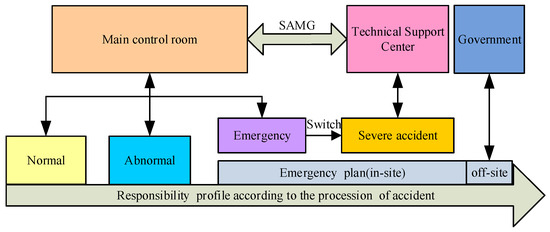
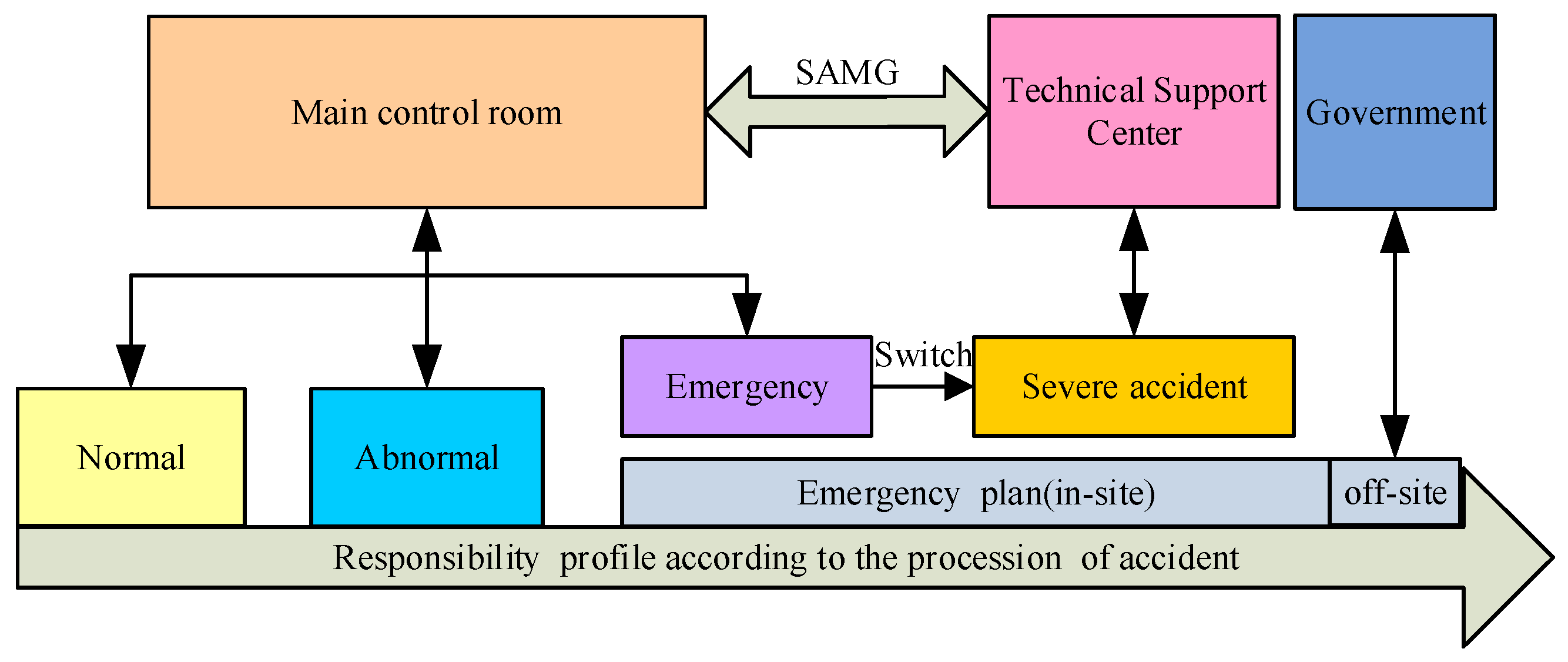
Figure 1 shows the responsibility profiles of NPP operations and accident management according to the NPP states. EOPs are continuously exercised by plant operators through the full-scale simulator. Thus, in the event of an emergency, staff in the main control room (MCR) may not ask for assistance from the support system before an accident occurs. Once core damage is imminent or has already taken place, dominated by the TSC, with the help of the main control room and field operators, SAMG will be enacted. The on-site emergency plan will be quickly set up when the NPP faces an accident. The EOPs and SAMG will be successively put into action to mitigate the accident. Once the radioactive materials are released into the environment from the containment or the spent fuel pool, the off-site emergency plan will be implemented to protect the public and the environment.
Figure 1.
Responsibility profiles of NPP operating and accident management.
Therefore, the support system described in this study is designed strictly as a decision aid for the TSC, rather than an autonomous control system, ensuring human oversight in strategy execution.
2.2. Function Elements of AMSS
Reflecting on the Fukushima accident, the high-intensity earthquake caused severe damage to the power grid, transportation, and other infrastructure outside the Fukushima area. After the connection between the external power grid and the Fukushima Daiichi nuclear power plant was interrupted, the plant’s internal power supply was switched over successfully, with emergency power systems continuing to supply electricity to the affected units. The safety systems associated with the three-level defense-in-depth strategy operated as designed. The safety system and equipment of the Fukushima nuclear power plant withstood the impact of the high-intensity earthquake. However, the tsunami coverage caused by the earthquake exceeded the designed protection capacity, breaking the essential conditions for the continuous normal operation of the emergency power supply in the plant, and putting the accident unit in a dangerous situation of losing all power supply and gradually losing DC power supply. At this time, the actual damage condition of the NPP—including the status of the reactor core, main control room (MCR), accident mitigation facilities, and emergency resources such as water and electricity—required the decision-makers to immediately carry out grade-level management of the accident.
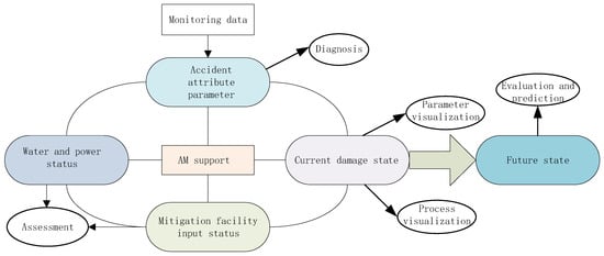
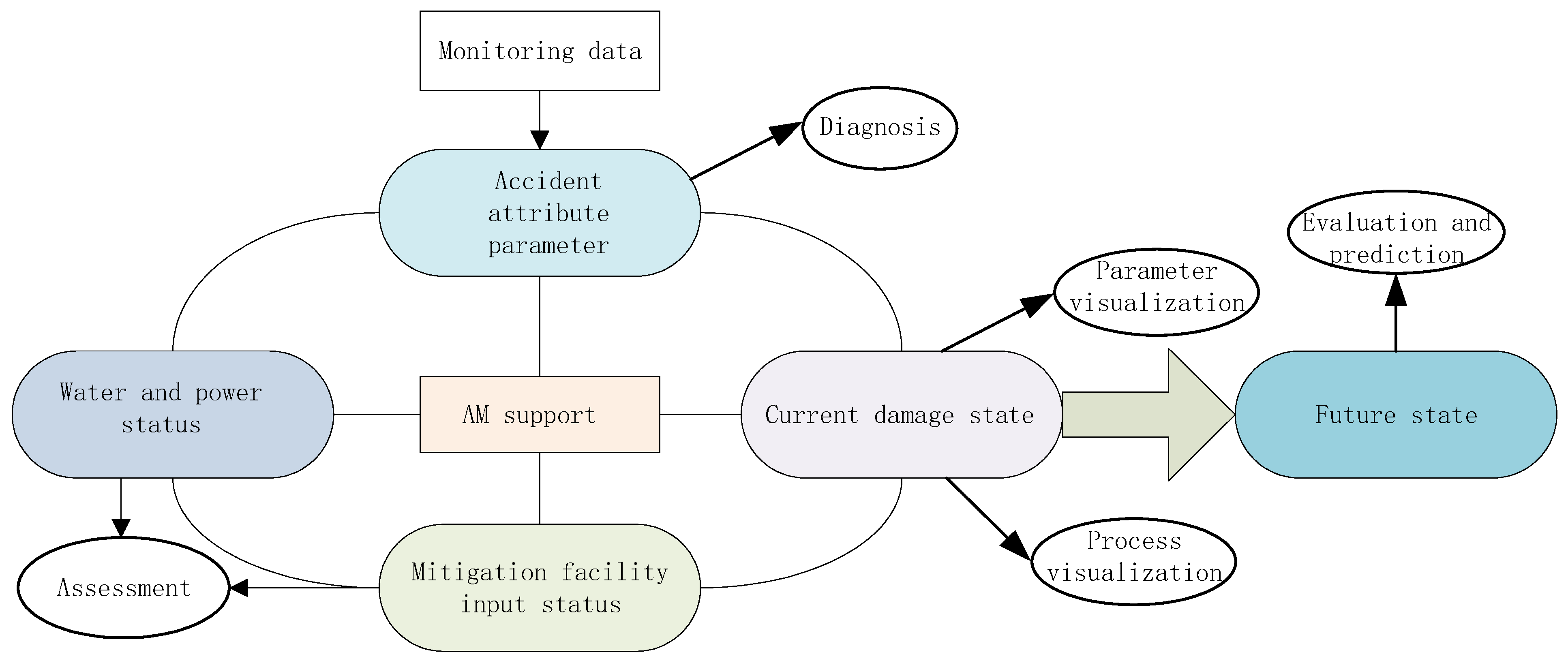
Considering the complexity of the accident, the uncertainty of the accident process, and the psychological pressure faced when dealing with the accident, management processes should be further refined. Through in-depth analysis and mining of real-time data, we can gain insight into the current state of the accident, review the accident occurrence and development history, evaluate the future development trend of the accident, and provide comprehensive, detailed, and user-friendly information support to the decision-makers (see Figure 2).
Figure 2.
Function elements of AMSS.
3. Framework of Online Support System
3.1. Technology Scheme
While RELAP5 and TRACE offer high-fidelity thermal-hydraulic analysis, their calculation time often exceeds real-time during complex transients. The code selected for this system prioritizes calculation speed (running 50× faster than real-time) to enable predictive trend analysis, which is crucial for the Digital Twin concept.
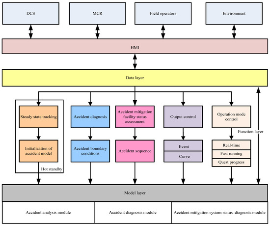
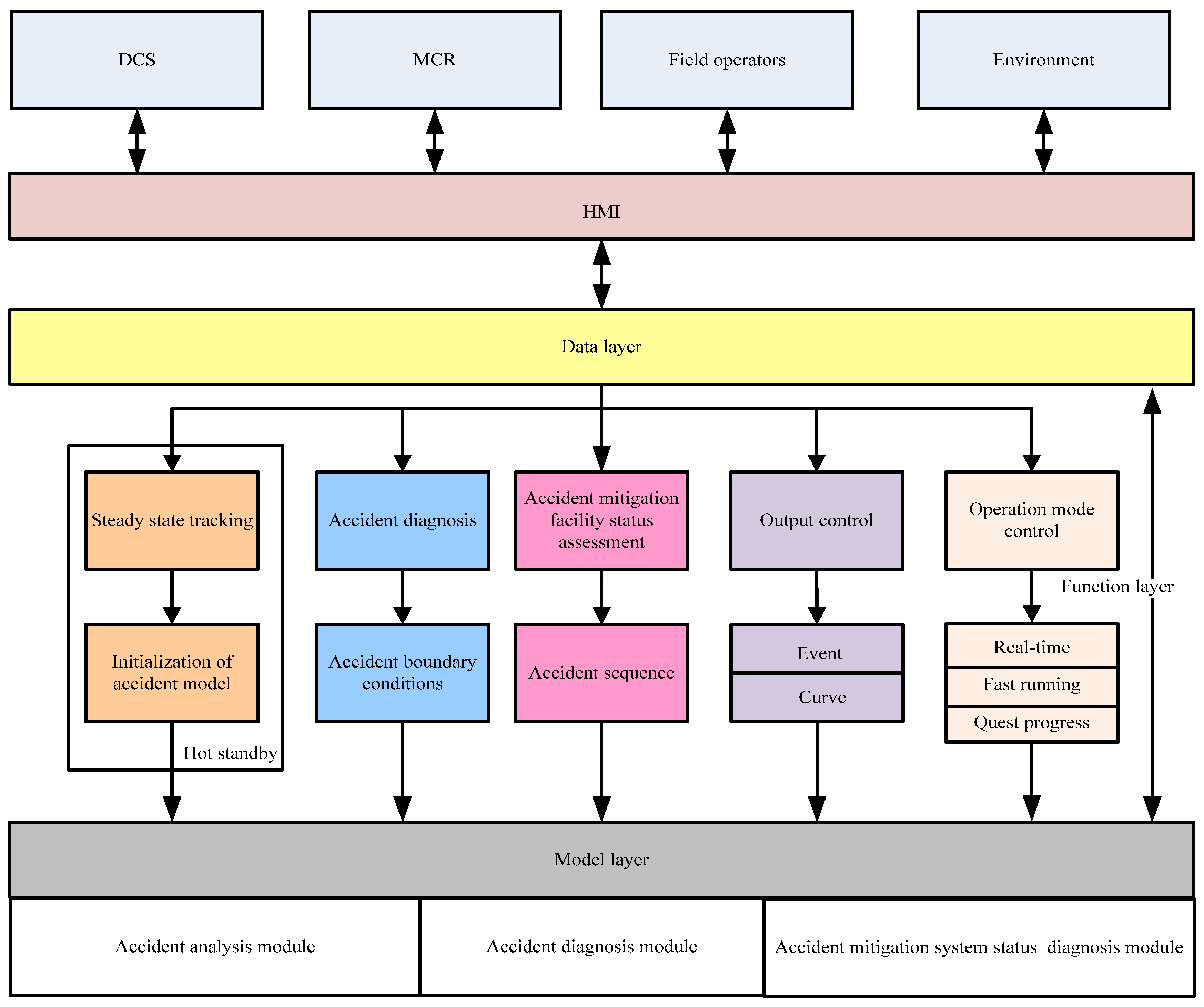
The framework of online accident management support has three layers: the data layer, the function layer, and the module layer (see Figure 3). Users can interact with the system through the human–machine interface (HMI) to transmit the information from DCS, MCR, and on-site operators, control the operation mode, and modify the results of accident diagnosis and the status of the accident mitigation system. In addition, the external environment information, like temperature, wind speed, and rainfall, can be viewed on-demand.
Figure 3.
Technology scheme of online support system.
The function layer consists of five modules: steady-state tracking, accident diagnosis, accident mitigation system status assessment, output control, and operation mode control. The steady-state tracking module is always in a hot standby to maintain consistency with the current NPP status. The accident diagnosis and accident mitigation system status assessment modules are always online, which are used to diagnose possible initial incidents and assess the status of the accident mitigation systems. In the module layer, the accident analysis module, accident diagnosis module, and accident mitigation system status diagnosis module support the function layer.
The diagnosis module operates in a continuous loop. Once a specific accident signature is identified with a membership degree > 0.8, the system triggers the “Accident Mode,” initializing the faster-than-real-time simulation using the current plant state as the boundary condition.
The online accident management support may potentially use any integral computer code of the thermal-hydraulic and fission product behavior within NPP. However, this module must be capable of representing the reactor core, the reactor coolant system, the containment, and adjacent plant buildings, as well as the emergency safeguard systems included in the design to protect the reactor core and containment. Furthermore, to meet the needs of an accident management application for multiple near-term predictions, the integral system module must run much faster than real-time. Such capabilities are needed to provide the accident management team with information to make well-informed decisions in a timely manner. Moreover, it is important to benchmark the integral system representation against the available separate effects experiments, integral experiments, and industry experience. Fast-Running Integral Code is one of the codes that can fully meet all these needs. Hence, it is the code of choice used in the representation.
No matter what the external disaster is, the NPP accident state can be defined as the initial accident properties (accident type, location, or break area if it is a pressure boundary breakage) and the status of equipment and facilities, which can give a complete description of the accident occurrence and development sequence. The initial accident can be categorized as LOCA, MSLB, SGTR, SBO, ATWS, and so on.
3.2. Post Profile
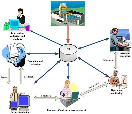
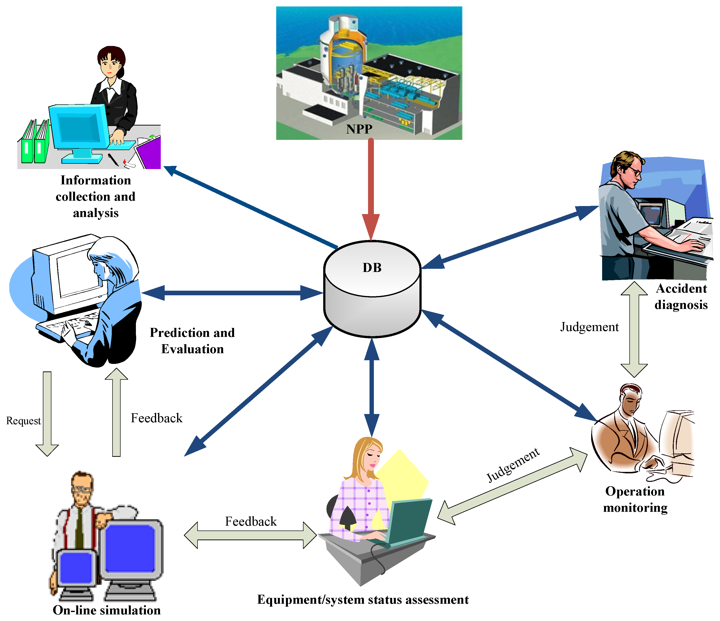
The human–computer interaction layer described in Figure 3 mainly consists of operation supervision, accident diagnosis, equipment/system condition assessment, online simulation, prediction and evaluation, and information collection and analysis, as shown in Figure 4.
Figure 4.
Post composition.
Online technical support for NPP accident management is conducted through the collaborative work of each functional position and can provide information to support the decision-making related to accident management. The “early detection” will be implemented by the operation monitoring post, and the staff of this post will evaluate the collected operation data in real time to grasp the current operation status in a timely and comprehensive manner. Once an accident occurs, the accident status and safety facility response status will be evaluated by the staff of accident diagnosis and equipment/system status assessment, providing the required IC and BC information to the staff of online simulation. The prediction and evaluation staff will receive technical support requests from the accident management command level, formulate prediction and evaluation requirements, and cooperate with the online simulation staff to realize the prediction of future trends based on the current accident status and the comprehensive effectiveness evaluation of accident mitigation measures. The information collection and analysis personnel collate and organize the information in the shared database to provide comprehensive and detailed technical support information for the accident management command level.
4. Online Simulation of Nuclear Reactor Accident
4.1. Logic of Progress Advance for Interactive Simulation
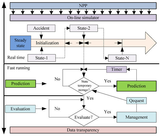
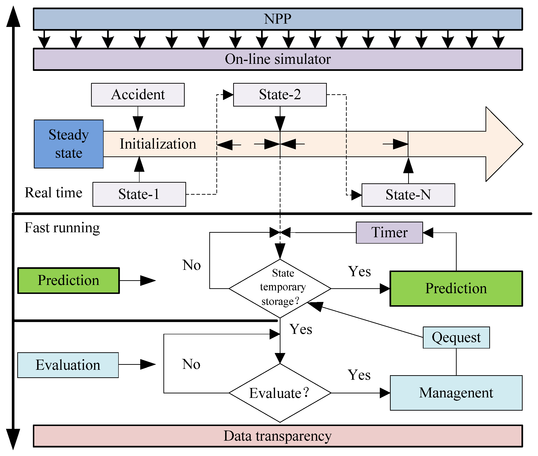
Figure 5 shows the logic of the interactive simulation process advancement for real-time online simulation, prediction, and evaluation. Through human–computer interaction interface, API interface, and underlying control logic, the simulation process propulsion control with Fast-Running Integral Code as the core computing engine is realized to meet the requirements of real-time operation, providing transparency of the current NPP accident states.
Figure 5.
Logic of progress advancement for interactive simulation.
In order to support the prediction of accident trends and the evaluation of mitigation strategies based on the current NPP states, Fast-Running Integral Code also needs to run in hyper-real-time mode. The temporary storage function is set at the HMI, and the snapshot of the current accident state is taken via the restart function, which provides the starting boundary condition for trend prediction and mitigation strategy evaluation.
To address initialization uncertainty, the steady-state tracking module employs a data reconciliation method to align simulation parameters with plant data within a ±2% error margin before accident initiation.
For the initialization of the accident analysis model, two levels of operations are involved: steady-state initialization and process initialization. First, the initialization of the reactor, main coolant system, pressurizer, steam generator, and containment is realized by obtaining the plant operation parameters, thus calibrating the starting point of accident analysis. Second, the results of the initial accident diagnosis are used to define the attribute parameters. And the status of the current equipment/system will be used to build the dynamic accident sequence with the accident analysis program running in real-time mode.
The system maintains dual timelines: the “Monitoring Timeline” is synchronized with the wall-clock/DCS time, while the “Prediction Timeline” accelerates forward from the current state to project future plant status.
4.2. Data Interaction and Operation Control of Fast-Running Integral Code
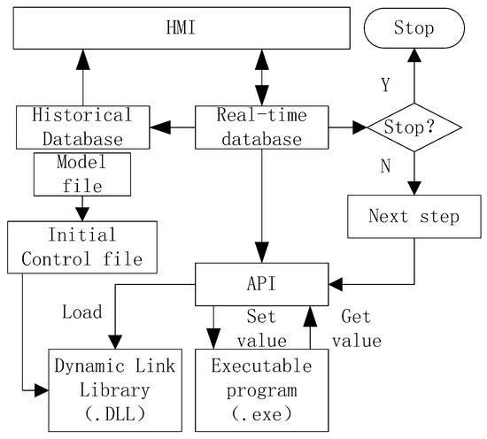
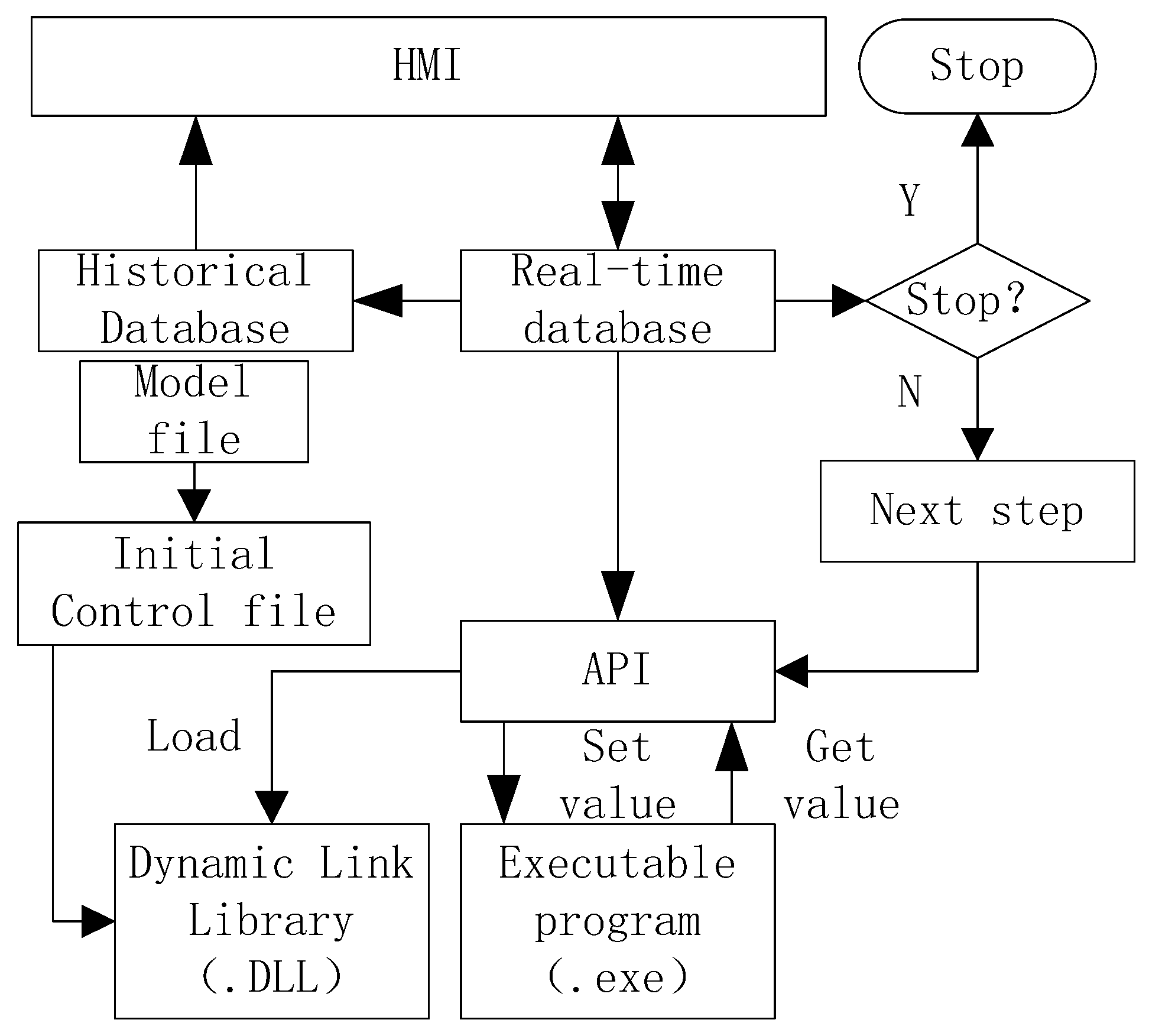
In order to realize the interactive operation of the Fast-Running Integral Code, the relevant control functions were developed and packaged using C#. The external control functions shown in Figure 6 have been developed for external scheduling of Fast-Running Integral Code, and the “SetDatas function” is used to transfer the results of the accident diagnosis and the operation status of the accident mitigation facilities to the Fast-Running Integral Code. The “GetDatas function” is used to extract the calculation results of Fast-Running Integral Code to meet the needs of the function layer data analysis and visualization requirements of HMI. According to the running mode, the real-time simulation can be achieved by interactively controlling the trigger of “Pause function” and the wake-up of “Restart function” based on the comparison of CPU time and physical time. By releasing the “Pause function”, the requirements of trend prediction and intervention plan evaluation can be satisfied, which is conducive to leveraging the fast calculation capability of Fast-Running Integral Code.
Figure 6.
Logic of data interaction and operation control.
Data exchange utilizes shared memory with a frequency of 10 Hz. The data format follows the standard C structure (float/double arrays). Error handling includes a checksum verification; if data is corrupted, the last valid frame is held for one cycle.
4.3. Scenario Validation
4.3.1. The Accident Scene
While Large Break LOCA represents the most severe challenge in terms of core uncovery timescales, an in-containment MSLB was explicitly selected for this initial verification to test the system’s capability to handle asymmetric secondary-side faults. Unlike LOCA, which is primarily a mass-loss event, MSLB introduces complex feedback loops between the secondary-side depressurization and primary loop overcooling. Successfully simulating this coupled response validates the system’s thermal-hydraulic stability. Validation against LOCA scenarios, which pose different challenges such as rapid hydrogen generation and containment pressurization, is identified as the immediate next priority in future work. The accident scenario was simulated by the AP1000 accident simulator based on the Fast-Running Integral Code, and the model has been adequately validated [15]. An in-containment MSLB accident at 1# SG was simulated with a break area of 2.5% of the main steam line flow area (0.5895 m2). The accident was injected into the simulator at full power under the following assumptions. It is also assumed that five minutes after the accident, the NPP will lose all AC power, and the emergency diesel engines will fail to start. The initial conditions are shown in Table 1.
Table 1.
Initial conditions.
The break area is derived iteratively by matching the simulated pressure drop rate dP/dt with the observed plant data, utilizing the critical flow model when the pressure difference is high.
- Passive residual heat removal (PRHR) is not available.
- Control volume system (CVS) is not available.
- Normal residual heat removal system (RNS) is not available.
- All stages of the auto depressurization system (ADS) are available.
- Only one core makeup tank (CMT) is available.
- Only one ACC is available.
- Internal refueling water storage tank (IRWST) gravity injection is not available.
- Cavity flooding is available.
- The containment cooling system (PCS) is available.
- Main feed water and start-up feed water systems are not available.
4.3.2. The Accident Diagnosis
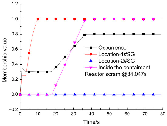
Once the occurrence of an incident is identified, the accident diagnosis module will continue to run the system and utilize the historical data to confirm the attribute parameters of the initial accident [16]. As the mass and energy from the SG secondary side were continuously released into the containment vessel, the malfunction of 1# SG was first detected about 10 s after the accident. Around 37 s after the accident, the SG secondary mass and energy releasing inside the containment is confirmed before the reactor shut down automatically (Figure 7).
Figure 7.
The diagnosis results of the accident.
Diagnosis Rules are judged as follows. If the value of the symptom is within the boundaries of a normal state, the memberships of increasing and decreasing are 0. When the value is between the high boundary of the normal state and the symptom’s high limit, the increasing membership is calculated by a linear equation based on the current value of the symptom. If it is between the low boundary of the normal state and the symptom’s low limit, the decreasing membership is also calculated by a linear equation. When the value of the symptom is higher than the high limit, the increasing membership is 1; if it is lower than the low limit, the decreasing membership is 1.
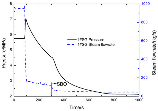
At 84.047 s, the reactor is triggered by high containment pressure. The main steam and main feedwater are then isolated automatically, while the start-up feedwater and CMT are activated automatically. At 300 s, due to the loss of all AC power, the SG lost all feed water. Figure 8 shows the trend of the damaged SG steam pressure and steam flow rate within 1000 s after the accident.
Figure 8.
Parameters of broken steam generator.
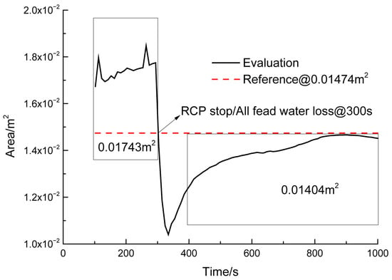
In this accident scenario, the break area is evaluated by selecting the time interval after reactor shutdown and main steam line isolation based on the monitoring parameters of the damaged SG, as shown in Figure 9. The estimated break area is 1.453 × 10⁻² m2 ± 2.16 × 10⁻⁴ m2 (Mean ± Standard Deviation), calculated over the stable diagnosis window (800 s–1000 s). This time window was selected because it represents the quasi-steady depressurization phase following the initial transient spikes caused by reactor trip and isolation valve closures. By 800 s, the hydrodynamic instabilities have settled, allowing for a more accurate correlation between pressure drop and break size. The confidence interval was derived from a sample size of N = 200 data points (sampled at 1 Hz over the 200 s window), ensuring statistical significance for the stability assessment. The 95% confidence interval for the estimation is [1.431 × 10⁻² m2, 1.475 × 10⁻² m2], demonstrating that the algorithm maintains stability despite process noise.
Figure 9.
Results of break area assessment.
After completing the main steam line break (MSLB) accident damage area assessment, the following accident attributes of FSGMSLB(1) = 1, ASGMSLB(1) = 1.453 × 10⁻² m2, and JNSGMSLB(1) = 6 are prepared to provide reliable input conditions for the subsequent online simulation of the accident scenario.
4.3.3. Equipment/System Status Assessment
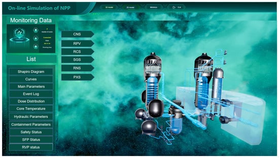
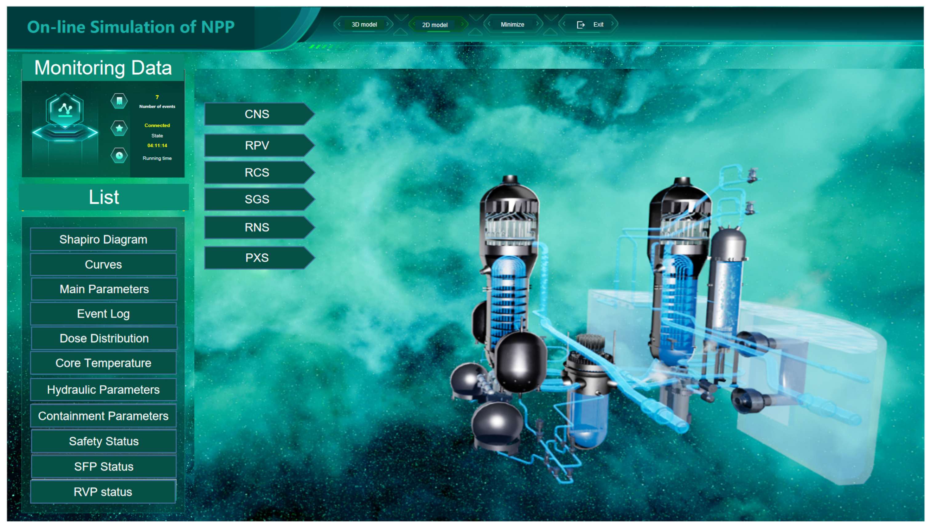
Collectively, the initial accident and the operational status of the accident mitigation facilities constitute a complete accident sequence fully consistent with the actual operational conditions of the nuclear power plant (NPP) (Figure 10). To enable an accurate online simulation of a nuclear reactor accident, it is not enough to obtain the type and property parameters of the initial accident; it is also necessary to map the accident mitigation facility’s working states to the Fast-Running Integral Code.
Figure 10.
Status panel of equipment and system.
4.3.4. Online Simulation of the Accident
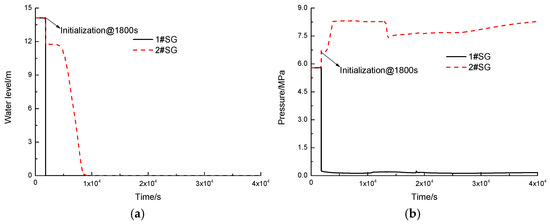
Considering the 30 min no-intervention principle, the system parameters within this period will be fully leveraged for the accident attribute analysis. The nuclear reactor accident simulator will start initialization based on the thermal parameters, the operation states of the equipment from the real-time simulation system, and the accident attributes prepared beforehand. Figure 11 shows the variation rule of secondary side parameters of the SGs. Due to the rupture of the main steam line, the water level of the secondary side of 1# SG is near zero at initialization, as shown in Figure 11a. The decay heat in the core is mainly brought out by 2#SG, and its steam pressure will remain near the set value of the relief valves for a period, as shown in Figure 11b.
Figure 11.
State parameters of SGs. (a) Water level. (b) Pressure.
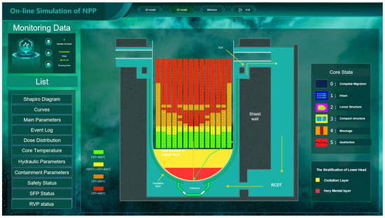
For the core state, the IGTYP(i) of each core node can be read by the “GetDatas” function and visualized as Figure 12. For the lower head melt pool, different colors are used to distinguish the light metal layer, oxide layer, and heavy metal layer, and the thickness of each layer is driven by the parameters from the “GetDatas” function. The parameters, such as heat flux distribution along the lower head and the thickness of the lower head, are represented as time-dependent parameter curves. The history curve tag in Figure 12 is an integrated display work interval, which can provide parameter curves of the NPP, not only the monitoring ones, but also by simulation, like the thickness of the lower head above.
Figure 12.
Interface of core state.
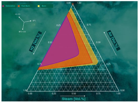
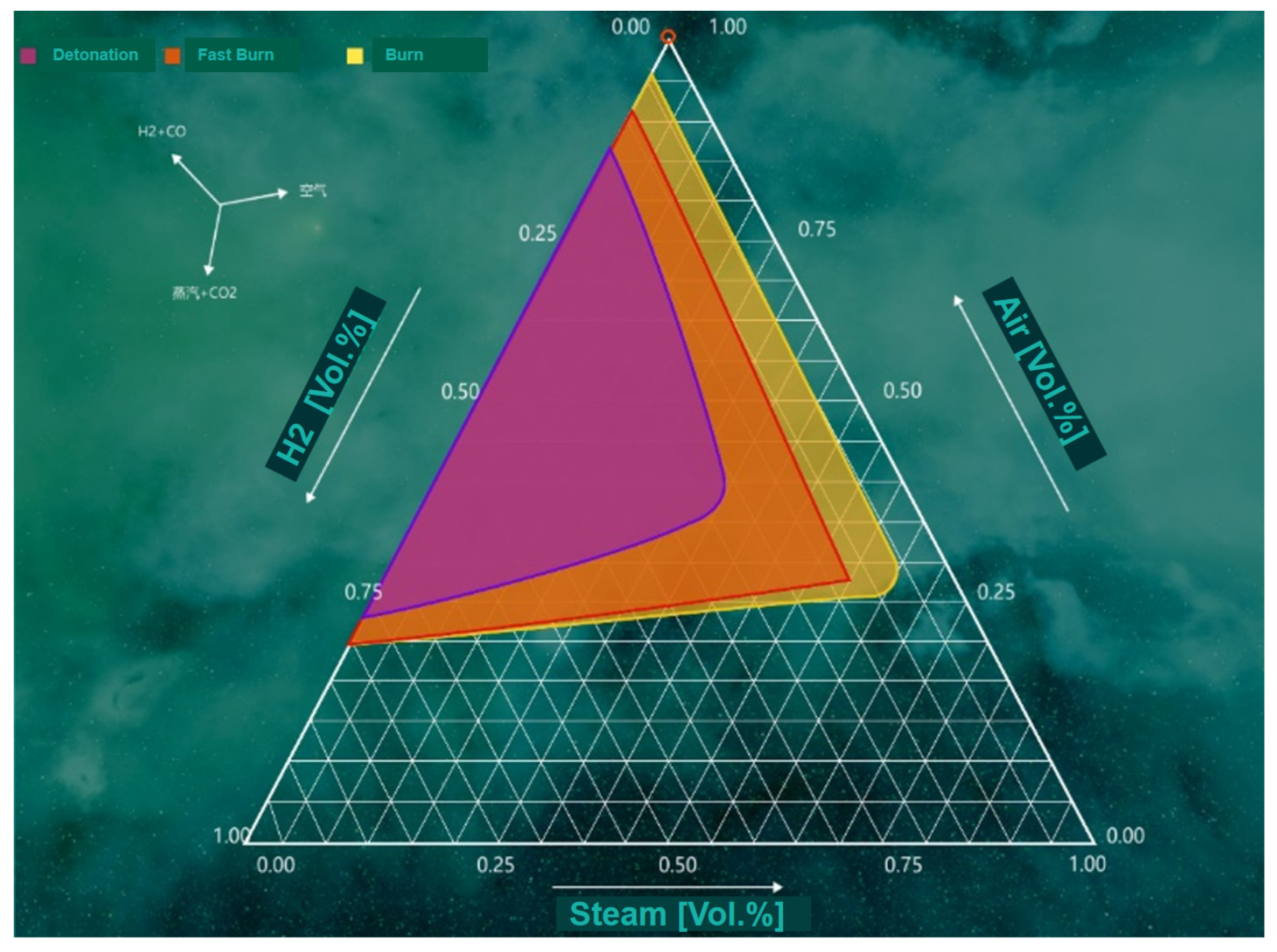
The outside real-time pressure and temperature will be used to calculate the risk of pressure-bearing failure trajectory carve of the containment, showing the relative relationship with the critical curve obtained by structural mechanics analysis under enveloping thermal parameters (inside pressure and temperature). Based on the state of the gas mixture within the containment, the hydrogen–air–water vapor ternary Shapiro diagram shown in Figure 13 will be used to assess and visualize the hydrogen risk of the containment.
Figure 13.
Assessment of hydrogen risk.
4.3.5. Evaluation of External Water Injection
For the accident scenario in this paper, once the passive safety injection system is exhausted or loses functionality, the core will inevitably heat up due to the continuous exposure. For incident mitigation, an external water injection strategy must be initiated promptly, using the RNS line to inject water into the primary loop. At 15,000 s, the real-time online simulation system is triggered to write the restart files.
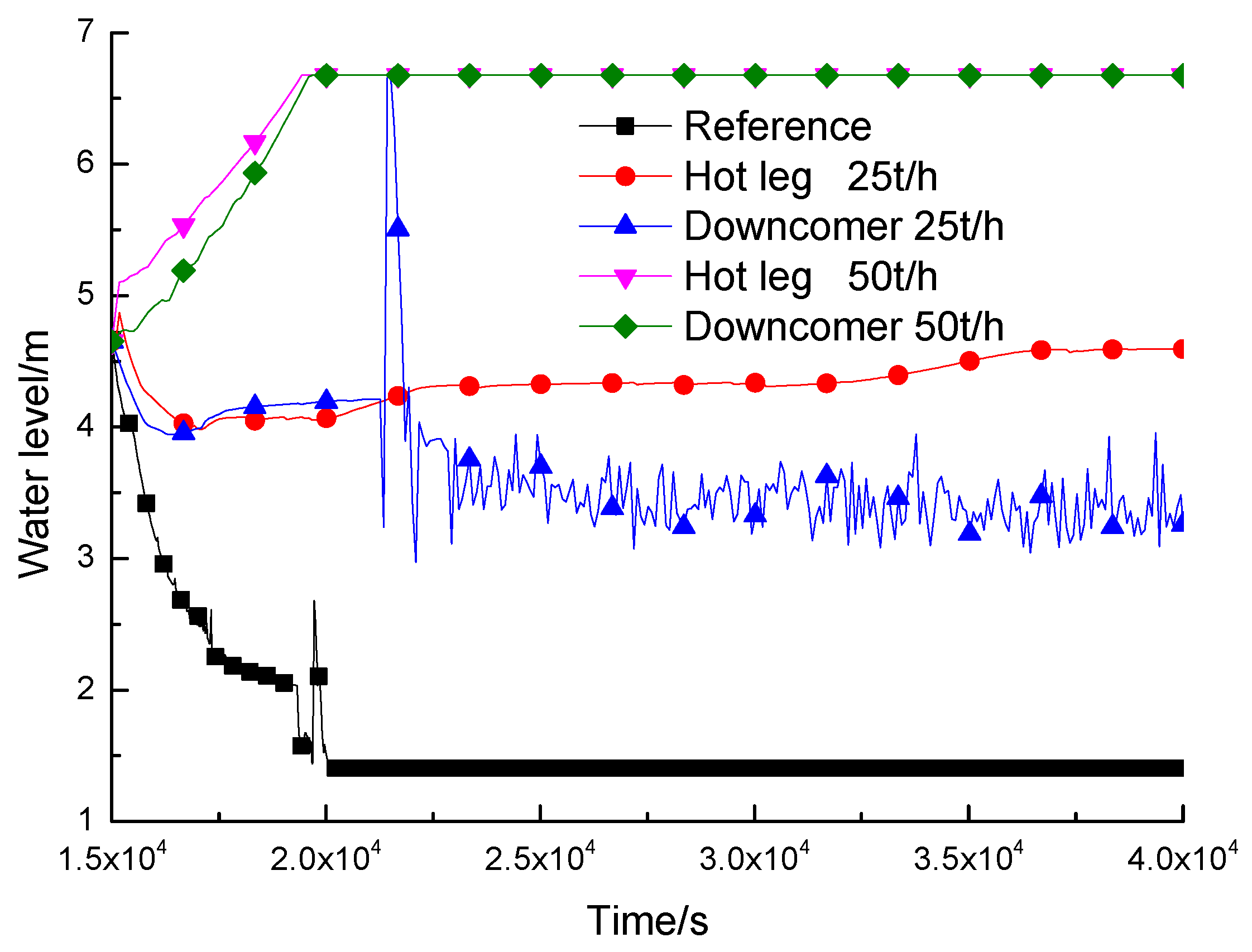
In order to evaluate the effects of injection points and injection flows on accident mitigation, the hot leg and downcomer are selected for the external water injection with injection flow rates of 25 t/h and 50 t/h at 50 °C, respectively. By executing the publish command, the additional files corresponding to these four evaluation tasks are generated, and process control files tailored to each assessment task are generated based on the general INP file and include command. The restart files prepared at 15,000 s are loaded synchronously with different external water injection parameters. The super-real-time computing capability of the Fast-Running Integral Code is used to perform synchronous and rapid analysis to realize the quantitative evaluation of the comprehensive effect of the water injection point and water flow rate. The simulation of a 1000 s accident sequence requires approximately 20 s of CPU time on a standard workstation (Intel i7, 16 GB RAM).
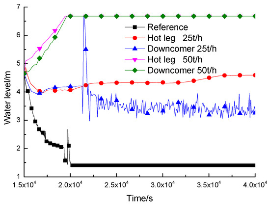
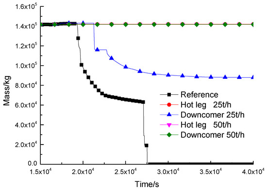
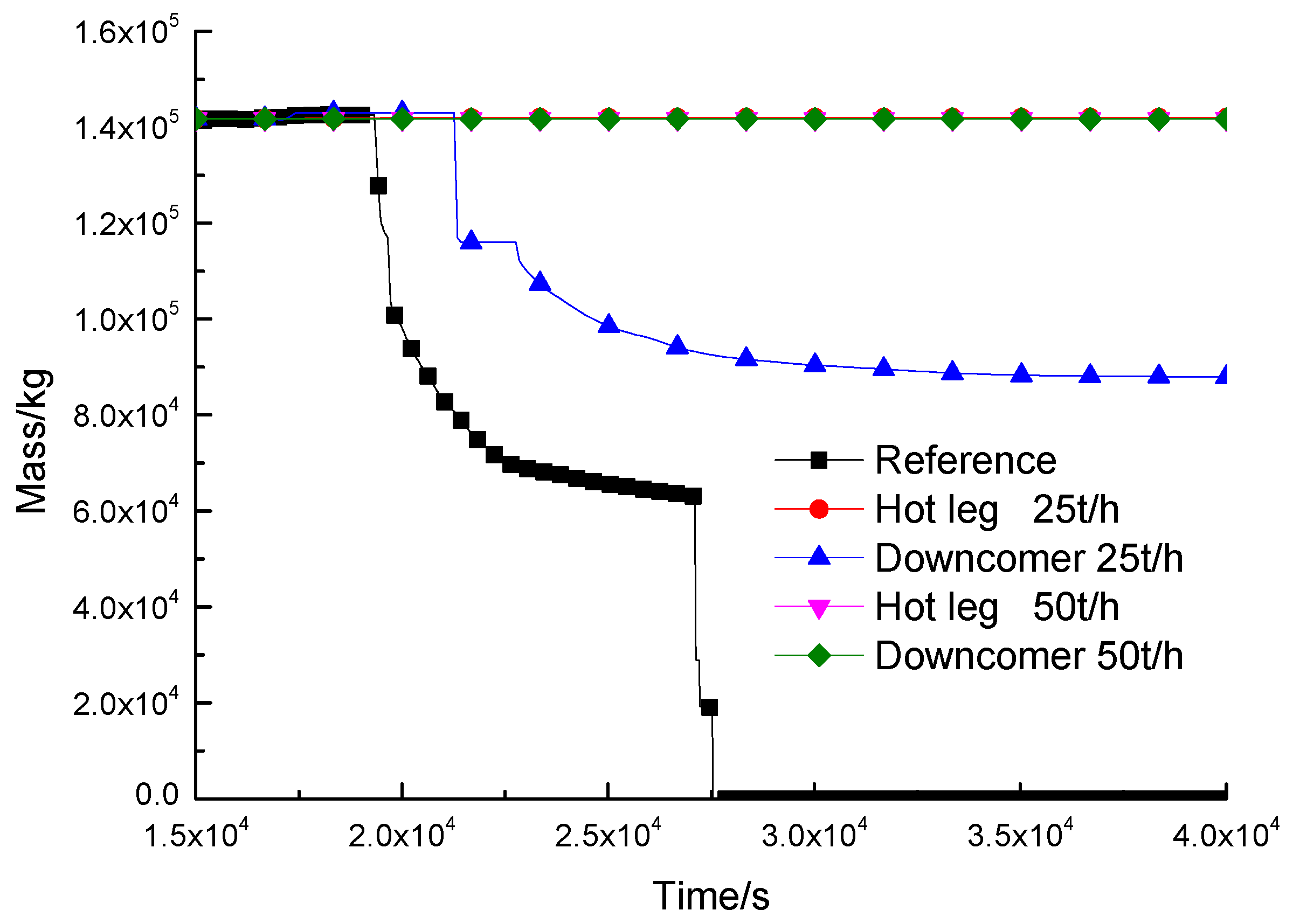
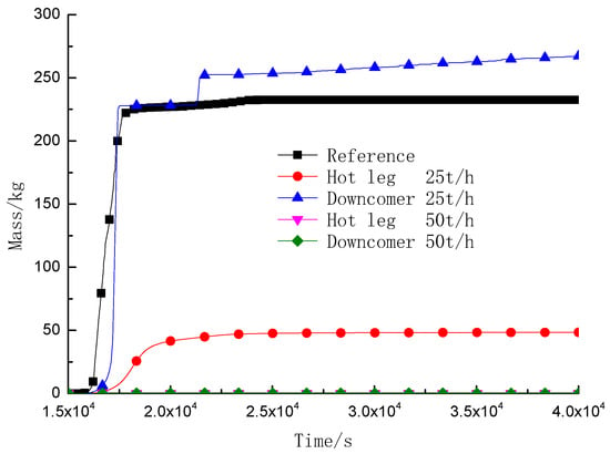
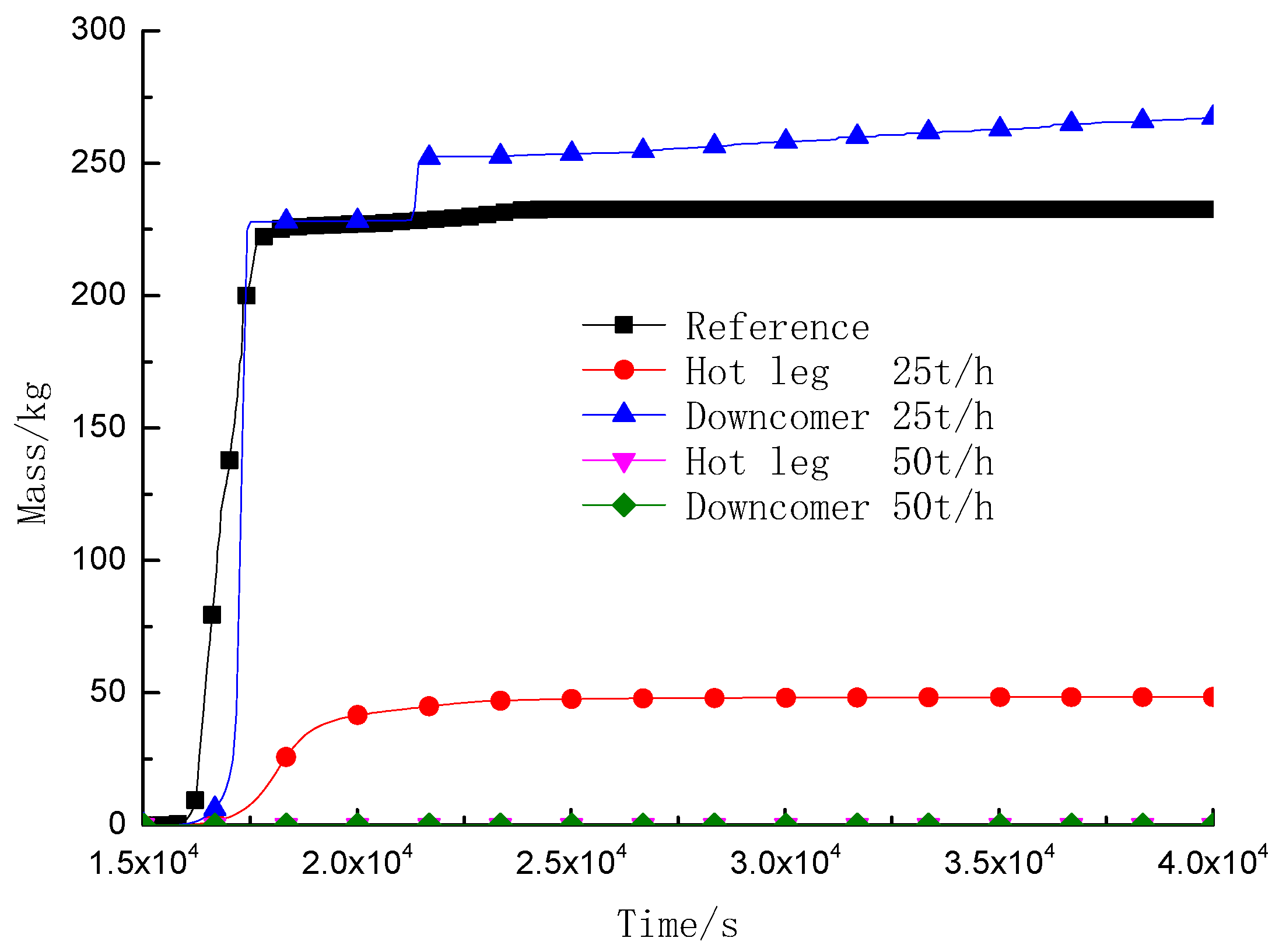
Figure 14 and Figure 15 show the comparison results of core water level and core mass with the reference, respectively. The validation is performed against the AP1000 Full Scope Simulator data, serving as the ground truth for this feasibility study. For an external water injection of 25 t/h, the accident mitigation effect through the hot leg is obviously better than that of the downcomer. In the case of a water injection flow of 50 t/h, the effect of the hot leg injection is basically the same as that of the downcomer. In the water injection mode of 25 t/h at the downcomer, the core melting cannot be prevented fundamentally with 50% of the core damage. In the 25 t/h at the hot leg, the core cooling can be maintained, thereby precluding further deterioration toward core meltdown.
Figure 14.
Comparison of core water level.
Figure 15.
Comparison of core mass change.
Sensitivity analysis shows that the ±1.5% uncertainty in break size estimation results in a deviation of approximately ±50 s in the predicted core uncovery time, which provides an acceptable margin for operator decision-making.
External water injection has both positive and negative effects. Figure 16 shows a comparison of the behavior of hydrogen generation in the reactor core under different external water injection strategies on the primary side. In the 25 t/h hot leg water injection mode, although the zirconium–water (Zr–water) reaction cannot be fundamentally prevented, hydrogen production is reduced to 20% of the reference case (no injection). Because the core resubmerging cannot be achieved completely, the hydrogen production of the core increases by 10% in this case compared to the reference condition. In the 25 t/h hot leg water injection mode, the hydrogen production in the reactor core is only 20% of the reference condition, although the Zr–water reaction could not be prevented fundamentally. For the external water injection strategy of 50 t/h, the core can be fully resubmerged, which ensures the effective cooling of the core and fundamentally avoids the occurrence of Zr–water reaction.
Figure 16.
Comparison of hydrogen production in core.
5. Conclusions
5.1. Demonstrated Capabilities vs. Operational Requirements
It is essential to demarcate the demonstrated feasibility in this study from the operational capabilities required for a universal support system. This work has successfully validated the data interaction workflow: the system correctly diagnosed a 2.5% MSLB event, triggered the Fast-Running Integral Code, and evaluated injection strategies within the “30 min non-intervention” window. However, this validation represents a proof of concept. The current diagnosis logic has been tested only against a single break size (2.5%). While the architecture is designed to be universal, its reliability across the full spectrum of break sizes (0.1–100%) and other accident types (e.g., LOCA and SGTR) remains to be quantified. The system currently serves as a decision-aid prototype, illustrating how simulation data can augment operator judgment, rather than an autonomous controller.
5.2. Integration with Human Decision-Making and SAMG
The automated recommendations provided by the system are intended to support, not replace, the Technical Support Center (TSC) staff. For instance, while the simulation confirms that hot leg injection is thermally effective during an SBO, the operational feasibility of aligning these valves manually is constrained by physical accessibility, lighting conditions, and radiation levels. Therefore, the system’s output must be integrated into the existing severe accident management guidance (SAMG) workflow. The system identifies “what is physically necessary” (e.g., 25 t/h injection), while the human decision-makers must determine “what is operationally possible” based on real-time environmental data. Future iterations of the interface will include “Feasibility Checklists” derived from SAMG to prompt operators to verify valve accessibility before attempting simulated strategies.
5.3. Conclusions
As an increasing amount of NPP information is made available in digital form, it will be feasible to provide operators with advanced information systems to support the assessment of the current plant status, with accidents being just a special case. This study proposes a framework of an online support system for NPP accident management, based on a comprehensive analysis of the operational and accident management profile, with the aim of providing the accident management team with essential information, including damage state assessment, prediction of possible progressions of the accident, and assessment of management actions. From the test results, it can be seen that the proposed framework is feasible and can enhance accident state transparency by making full use of the monitoring and simulation parameters.
In this framework, the programs and methods employed in the design and safety analysis of existing nuclear power plants are linked with the real-time data of the plants to map human, machine, object, environment, and process information in both the real space and simulation space, enabling the application of the “Digital Twin” concept in the field of accident management in NPP and providing deep-rooted and valuable information for the management of accidents and decision-making.
Online simulation is the key path to implementing the “Digital Twin” concept. In this paper, the Fast-Running Integral Code is selected as the core computing engine, an operation control strategy is formulated, and a technical solution of online nuclear reactor accident simulation is proposed, which realizes the holographic transparency of the accident states of the nuclear reactor, the prediction of the future development trend of the accident, and the quantitative evaluation of the accident mitigation measures.
The current research work is still preliminary, and more systematic evaluation and validation would need to be addressed before the actual implementation in NPPs.
6. Future Work
The current framework assumes sensor availability, which is a significant limitation for operational deployment, particularly in harsh containment environments where equipment may degrade. The diagnostic rules (Section 4.3.2) currently rely on direct parameter readings. Future development must incorporate signal validation algorithms and analytical redundancy (inferring lost sensor data from surviving instruments) as a critical design requirement to maintain diagnostic fidelity under degraded instrumentation conditions.
Based on the proof-of-concept results and the identified limitations, future research will prioritize the following areas to transition the system from feasibility to operational capability:
- Expansion of Scenario Library: Validation against LOCA scenarios (Small, Intermediate, and Large Break) to test the system’s response to rapid mass loss and containment pressurization.
- Robustness Testing: Conducting sensitivity analyses across a continuous spectrum of break sizes (0.1–100%) to quantify the diagnosis accuracy and boundary effects.
- False-Positive Analysis: Testing the diagnostic algorithms against normal plant transients and load-following maneuvers to quantify and minimize the false-positive rate.
- Resilience to Sensor Loss: Developing data reconstruction methods to handle scenarios with partial loss of instrumentation in the containment or secondary side.
Author Contributions
Conceptualization, L.F., F.S. and K.Z.; Methodology, L.F.; Software, G.J.; Formal analysis, L.F.; Investigation, M.W. and J.W.; Data curation, L.F. and M.W.; Writing—original draft, L.F.; Writing—review & editing, L.F.; Supervision, K.Z. All authors have read and agreed to the published version of the manuscript.
Funding
This research received no external funding.
Institutional Review Board Statement
Not applicable.
Informed Consent Statement
Not applicable.
Data Availability Statement
The original contributions presented in this study are included in the article. Further inquiries can be directed to the corresponding author.
Acknowledgments
Thanks for support for The post-CHF heat transfer test study of LBLOCA Ejection and refill stage (042300033222).
Conflicts of Interest
The authors declare no conflict of interest.
References
- OECD. Fukushima Daiichi Nuclear Power Plant Accident, Ten Years On: Progress, Lessons and Challenges; OECD: Paris, France, 2021. [Google Scholar]
- Raines, J.; Hammersley, R.; Henry, R.; Blaisdel, J.; Bonaca, M.; Khalil, Y. MARS—An accident management tool. In Proceedings of the Specialist Meeting on Severe Accident management and Training, Norway, Halden, 8–10 June 1993. [Google Scholar]
- Taminami, T.; Kubota, R.; Fujiwara, T.; Yamane, N.; Takizawa, Y. Development of Emergency Response Support System for Accident Management. In Proceedings of the Second OECD Specialist Meeting on Operator Aids for Severe Accident Management (SAMOA-2), Lyon, France, 8–10 September 1997. [Google Scholar]
- Fantoni, P.F.; Sørensen, A.; Mayer, G. CAMS: A Computerised Accident Management System for Operator Support during Normal and Abnormal Conditions in Nuclear Power Plants. In Proceedings of the Second OECD Specialist Meeting on Operator Aids for Severe Accident Management (SAMOA-2), Lyon, France, 8–10 September 1997. [Google Scholar]
- Vayssier, G.; Fantoni, P.; Borondo, L.; Martinez, R.; Krajnc, B.; Dessars, N.; Husarcek, J.; Bahna, J. A perspective on computerized severe accident management operator support SAMOS. In Proceedings of the ANS Annual Meeting, Reno, NV, USA, 4–8 June 2006. [Google Scholar]
- Khatib-Rahbar, M.; Zavisca, M.; Esmaili, H.; Cazzoli, E.; Schmocker, U.; Schoen, G.; Schulz, R. Accident diagnostic, analysis and management (ADAM) system applications to severe accident management. In Proceedings of the OECD/NEA Severe Accident Management (SAM) Workshop on Operator Training and Instrumentation Capabilities, Lyon, France, 12–14 March 2001. [Google Scholar]
- Zavisca, M.J.; Khatib-Rahbar, M.; Esmaili, H.; Schulz, R. ADAM: An accident diagnostic, analysis and management System—Applications to severe accident simulation and management. In Proceedings of the 10th International Conference on Nuclear Engineering, Arlington, VA, USA, 14–18 April 2002; American Society of Mechanical Engineers: New York, NY, USA, 2002. [Google Scholar]
- Ahn, K.-I.; Park, S.-Y. Development of a risk-informed accident diagnosis and prognosis system to support severe accident management. Nucl. Eng. Des. 2009, 239, 2119–2133. [Google Scholar] [CrossRef] [Scilit]
- Park, S.Y.; Ahn, K.I. SAMEX: A severe accident management support expert. Ann. Nucl. Energy 2010, 37, 1067–1075. [Google Scholar] [CrossRef] [Scilit]
- Yoo, K.H.; Back, J.H.; Na, M.G.; Hur, S.; Kim, H. Smart support system for diagnosing severe accidents in nuclear power plants. Nucl. Eng. Technol. 2018, 50, 562–569. [Google Scholar] [CrossRef] [Scilit]
- Zachary, J.; Troy, H.; Matthew, D. How to ADAPT; SAND2018-6660; Sandia National Laboratories: Albuquerque, NM, USA, 2018. [Google Scholar]
- Bohanec, M.; Vrbani, I.; Bai, I.; Debelak, K.; Trubelj, L. A decision-support approach to severe accident management in nuclear power plants. J. Decis. Syst. 2020, 29, 438–449. [Google Scholar] [CrossRef] [Scilit]
- National Academies of Sciences. Lessons Learned from the Fukushima Nuclear Accident for Improving Safety of U.S. Nuclear Plants; National Academies Press (US): Washington, DC, USA, 2014. [Google Scholar]
- Xu, H.; Zhang, B.; Liu, Y. New safety strategies for nuclear power plants: A review. Int. J. Energy Res. 2021, 45, 11564–11588. [Google Scholar] [CrossRef] [Scilit]
- Wang, M.; Chen, W.Z.; Tao, Y.Y. The transient performances of AP1000 core debris in-vessel retention system under the conservative scenario of DVI line break. Ann. Nucl. Energy 2022, 165, 108778. [Google Scholar] [CrossRef] [Scilit]
- Wang, M.; Chen, W.Z. The detection and diagnosis model for small scale MSLB accident. Nucl. Eng. Technol. 2021, 53, 3256–3263. [Google Scholar] [CrossRef] [Scilit]

Disclaimer/Publisher’s Note: The statements, opinions and data contained in all publications are solely those of the individual author(s) and contributor(s) and not of MDPI and/or the editor(s). MDPI and/or the editor(s) disclaim responsibility for any injury to people or property resulting from any ideas, methods, instructions or products referred to in the content. |
© 2026 by the authors. Licensee MDPI, Basel, Switzerland. This article is an open access article distributed under the terms and conditions of the Creative Commons Attribution (CC BY) license.