


Abstract
Dynamic failure of roadways subjected to mining-induced seismicity poses a major challenge to support design and coal burst control in deep coal mines. Using the roadway of the 3102 working face at M Coal Mine in Inner Mongolia, China, as the engineering background, a UDEC-Trigon model was established to compare four support schemes: unsupported, bolt support, combined bolt and cable support, and combined support with bolts, cables, and hydraulic props. The results show that support configuration significantly affects roadway deformation, particle velocity, stress redistribution, and fracture development. Bolt support alone provides limited improvement, whereas the introduction of cables markedly reduces rib deformation, high-velocity ejection zones, and fracture propagation. The maximum left- and right rib displacements decrease from 0.75 and 0.65 m under the unsupported condition to 0.12 and 0.25 m under combined bolt and cable support, respectively. Tensile cracks are more widely distributed than shear cracks, with tensile failure dominating the shallow surrounding rock and shear failure occurring mainly in deeper zones. Fractal analysis further indicates that combined bolt and cable support effectively suppresses crack development and reduces fracture network complexity, whereas hydraulic props provide only limited additional improvement. Based on the numerical results, an optimized bolt and cable reinforcement scheme combined with roof pre-splitting blasting was implemented in the field. The maximum deformations of the roof, ribs, and bottom were reduced by 40.0%, 60.0%, and 55.6%, respectively. These findings provide a reference for support design and coal burst mitigation in deep coal roadways.
1. Introduction
Dynamic failure of roadways and coal bursts are major hazards in deep coal mining [1,2]. Mining-induced seismic events generated by the fracture of thick and hard roof strata can act as external dynamic disturbances triggering instability of roadways [3]. The severity of roadway failure depends not only on source energy but also on roadway supports [4,5]. Therefore, clarifying the interaction between the surrounding rock and support elements under seismic loading and evaluating the effectiveness of different support combinations are important for assessing roadway stability.
Previous studies on roadway dynamic instability have addressed critical stress, structural stiffness, and energy transformation. Frith et al. [6] proposed a causation model for coal bursts during roadway development. Ren et al. [7] used the energy extreme point method and showed that the ratio of roadway width to height, roof stiffness, and coal–rock interface properties can alter the critical conditions, while support can increase the critical load. Ju et al. [8] combined coupled finite and discrete element simulations with physical model tests to reveal the effects of roof stiffness and superimposed dynamic loading on roadway failure modes and energy conversion. Tan et al. [9] considered nonhydrostatic stress states and postpeak softening and found that the initial stress and lateral pressure coefficient are key factors governing energy evolution around rectangular roadways. Zhou et al. [10] used numerical simulations and field observations to quantify topography-induced stress disturbance in gully regions and proposed a hazard classification. Dai et al. [11] derived stress thresholds from the interaction between borehole convergence and sensor deformation. Liu et al. [12] combined physical similarity experiments and UDEC (version 6.0) simulations to show that increasing static stress promotes a transition from localized damage to overall impact-induced collapse in thick-top-coal roadways. Zuo et al. [13] derived the ejection velocity of rock fragments from an energy balance framework, whereas Li et al. [14], through true triaxial transient unloading tests on granite, demonstrated that excess energy is closely related to fragment ejection velocity and mass. Akdag et al. [15] reproduced rock and coal bursts using a modified thick-walled hollow-cylinder testing system under polyaxial loading. Zhang et al. [16] identified segmented thrust-fault slip and the associated clamping effect as sources of stress concentration. Wu et al. [17] found that dynamic disturbance can reduce bolt elongation capacity and residual energy absorption, while shear localization can further weaken reinforcement efficiency. Kang et al. [18] used tests involving pretension, impact, and tension and showed that pretension can restrain bolt deformation and vibration after impact. By contrast, impact tests on prestressed anchorage systems by Wang et al. [19] indicated that excessive prestress can reduce the energy absorption reserve. Repeated impact similarity tests by Wu et al. [20] showed that bolt support can delay roof separation and collapse, although repeated impacts produce cumulative support damage. Karatas Batan et al. [21] further demonstrated that both component performance and support configuration affect system energy absorption, and that increasing bolt length beyond the potential failure zone thickness provides diminishing benefit.
To improve deformation capacity and energy absorption, various yielding and energy-absorbing support components have been developed. Pytel et al. [22] tracked the acceleration, velocity, and displacement of rib blocks using a limit equilibrium approach and showed that friction stabilizers can restrain block ejection by permitting controlled displacement. Zhu et al. [23] found in shear tests under constant normal stiffness that negative Poisson ratio bolts sustained shear displacements greater than 15 mm, whereas conventional bolts failed at displacements below 6 mm. Xu et al. [24] optimized sinusoidal negative Poisson ratio energy-absorbing structures and showed that wall thickness and amplitude jointly govern bearing and deformation performance. In engineering practice, reinforcement is commonly combined with stress regulation. Zhang et al. [25] integrated theoretical analysis, FLAC–PFC coupled simulation, and field monitoring to arrange roadways beneath a gob and to treat local high-stress regions using large-diameter boreholes and roof pre-splitting blasting. Combined dynamic and static shear tests by Zhang et al. [26] showed that increasing borehole diameter reduces shear strength and alters the roadway plastic zone. Yu et al. [27] combined high prestress cable support with directional hydraulic fracturing to control asymmetric failure caused by eccentric loading and dynamic disturbance in a roadway. Liu et al. [28] combined an elastoplastic foundation model with 3DEC simulations to distinguish zonal energy release during thick-hard roof fracture and subsequent structural instability.
Discrete element modelling provides an effective tool for investigating crack propagation and dynamic failure. Chen et al. [29] used discrete element simulations of coal specimens containing predefined voids to reveal the effects of void number and distribution on crack evolution, strength, and energy migration. Zhang et al. [30] employed a breakable Voronoi block model to distinguish energy dissipation on newly generated fracture surfaces from the kinetic energy of moving blocks. Qiu et al. [31] developed a hierarchical block model to characterize tensile, shear, and mixed-mode fracturing under different confining pressures. Gao et al. [32] reproduced roadway squeezing under mining-induced stresses, including roof sag, rib deformation, and bolt failure. Cao et al. [33] investigated mining-induced seismicity-triggered coal bursts and identified tensile failure near the roadway surface and shear failure in deeper regions. Zhang et al. [34] investigated roadway instability and identified coupled interface slip and fracture during excavation unloading, with crack development transitioning from shear to tensile failure.
Recent studies have clarified the roles of initial stress, support component performance, pressure relief, and fracture evolution in roadway dynamic instability. However, the relative influence of commonly used support combinations on deformation, particle velocity, stress redistribution, and tensile and shear fracture development under a consistent mining-induced seismic disturbance remains insufficiently quantified.
To address these issues, this study compares four roadway support configurations under identical initial stress and prescribed dynamic loading conditions using a UDEC-Trigon model. The comparative analysis combines roadway displacement and velocity histories, maximum principal stress redistribution, tensile and shear crack patterns, and box-counting fractal dimensions. Based on the numerical results, an optimized support scheme was proposed and evaluated through field deformation monitoring. This study provides a reference for selecting support measures for coal roadways subjected to mining-induced seismic events.
2. Engineering Background
2.1. Geological and Mining Conditions
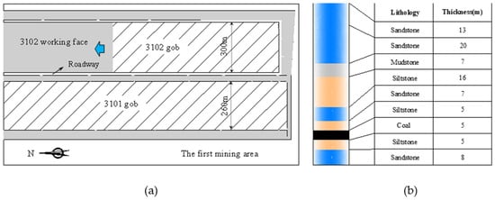
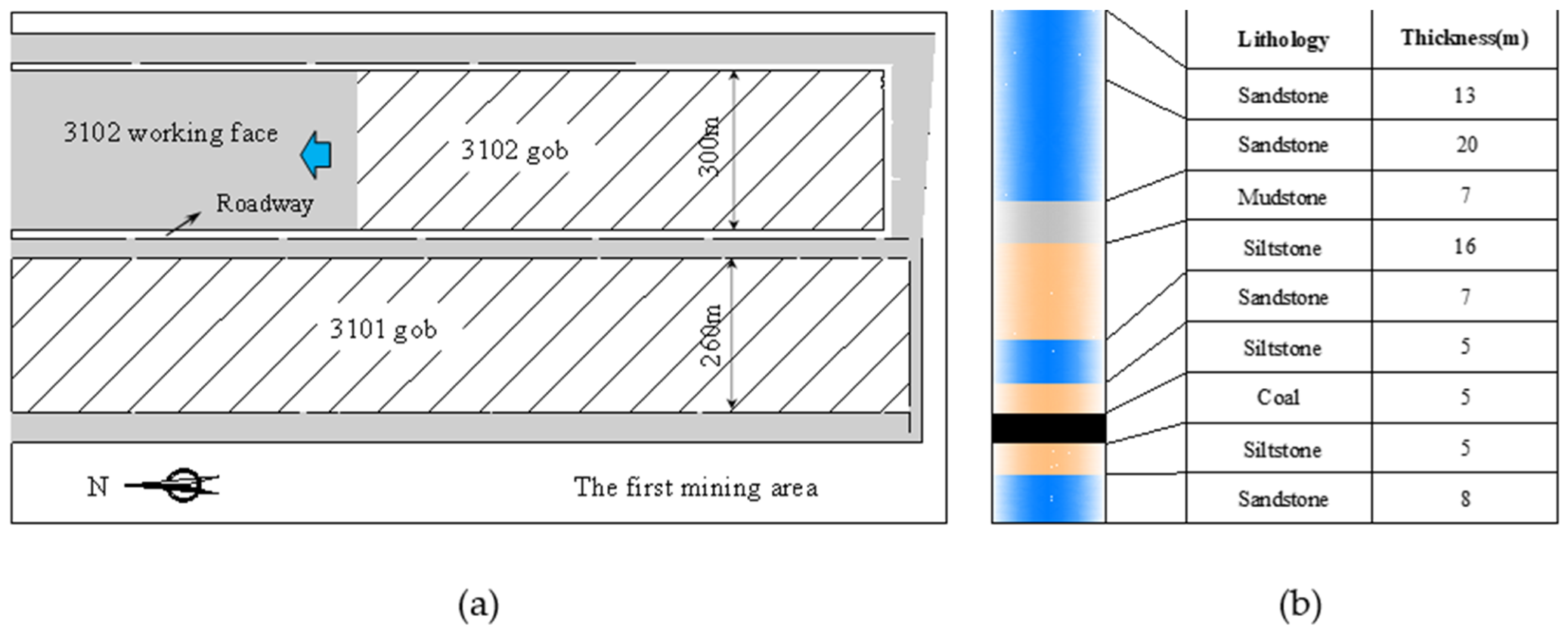
M Coal Mine is located in Inner Mongolia, China. Two working faces, 3101 and 3102, were developed in the first mining district. The coal seam has an average burial depth of 692 m, an average thickness of 5 m, and an average dip angle of 2°. As shown in Figure 1a, the 3101 and 3102 working faces are 260 and 300 m wide, respectively. By the time the 3102 working face was mined, extraction of the 3101 working face had been completed, leaving a coal pillar between the two panels. The lithology and thicknesses of the roof and floor strata are shown in Figure 1b. Several roof strata are more than 10 m thick and have high uniaxial compressive strength. Field monitoring showed that fracture of these competent roof strata was accompanied by mining-induced seismic events with energies greater than 1.0 × 10⁵ J.
Figure 1.
Geological and mining conditions of the study area: (a) layout of the 3102 working face; (b) lithological column of the roof and floor. The arrow indicates the advance direction of the 3102 working face.
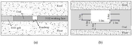
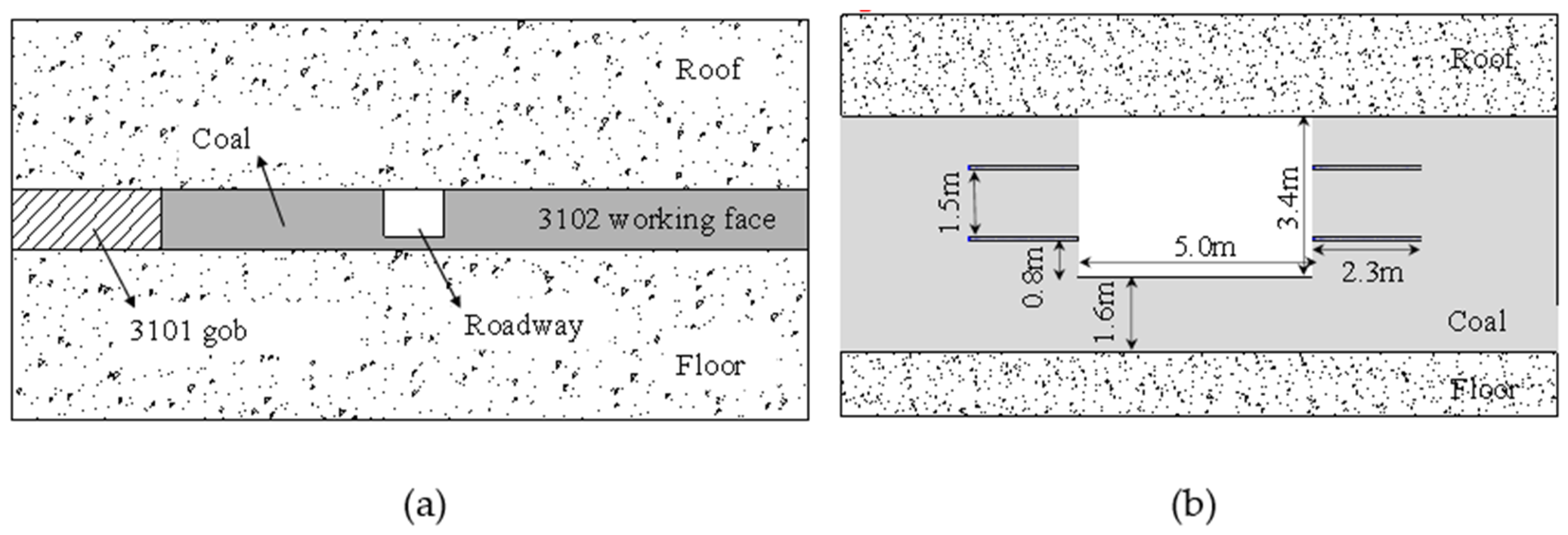
During mining of the 3102 working face, the roadway near the 3101 gob frequently experienced dynamic failure. As shown in Figure 2a, the roadway is driven within the coal seam, with the 3101 gob on one side and the 3102 working face on the other. The original support arrangement is shown in Figure 2b. The roadway has a rectangular cross-section, 5.0 m wide and 3.4 m high, with 1.6 m of bottom coal beneath the roadway. Both ribs are reinforced by two rows of horizontally installed bolts. The bolts are 2.3 m long and 20 mm in diameter. The vertical spacing between the two bolt rows is 1.5 m, the spacing along the roadway is 0.8 m, and the lower bolt row is 0.8 m above the roadway bottom. The bolts confine the rib coal and enhance its load-bearing capacity. In the original roadway, two roof bolts approximately 1.8 m long were also installed. Field observations indicated that these roof bolts had lost their load-bearing capacity under repeated mining-induced disturbances before the April 2018 coal burst.
Figure 2.
Roadway layout and support scheme: (a) spatial relationship among the 3101 gob, roadway, and 3102 working face; (b) support scheme.
2.2. Roadway Failure Characteristics
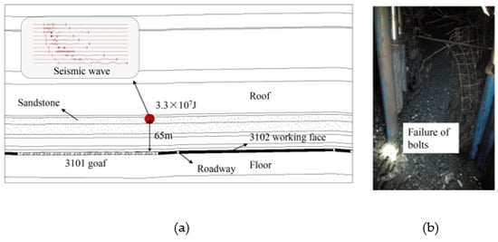
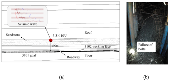
In April 2018, a severe coal burst occurred in the roadway under the combined action of high static stress in the coal seam and dynamic loading generated by roof fracture. According to the micro-seismic monitoring system at M Coal Mine, the associated mining-induced seismic event occurred approximately 65 m above the coal seam and released 3.30 × 10⁷ J of energy. The recorded seismic velocity is presented with its time and amplitude axes in Figure 3a. The amplitude spectrum of the recorded signal contains a prominent component near 80 Hz, together with low-frequency components below 10 Hz, indicating that the measured disturbance comprises multiple frequency components. The event caused rib and bottom coal deformations approaching 1.0 m and severe damage to the roadway support, as shown in Figure 3b. This event demonstrates that the original support system was insufficient to control roadway deformation under strong seismic disturbance.
Figure 3.
Mining-induced seismic event and coal burst: (a) seismic waveform; (b) failure of support.
The seismic source was approximately 65 m above the coal seam and is associated with an upper sandstone interval in Figure 1b. The pre-event deformations of the left rib, right rib, and bottom coal were 0.30, 0.35, and 0.12 m, respectively. Subtracting these from the cumulative values gives event-associated deformation increments of approximately 0.70, 0.65, and 0.88 m.
3. Numerical Model and Simulation Scheme
3.1. UDEC-Trigon Numerical Model
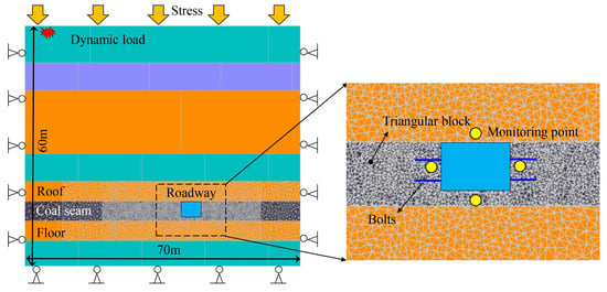
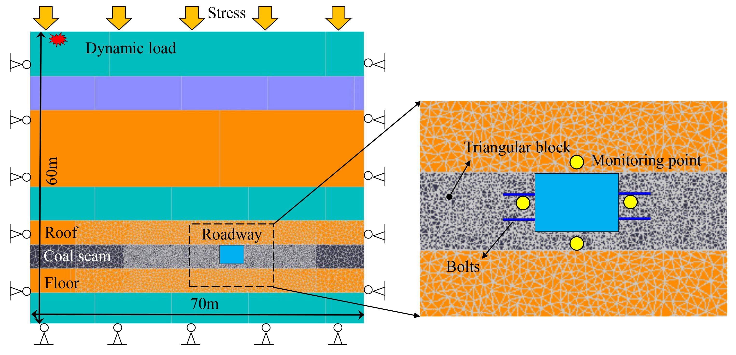
A two-dimensional UDEC-Trigon model was established using UDEC 6.0 to simulate the dynamic response of the roadway. The model measures 70 m in width and 60 m in height, as shown in Figure 4. The region around the roadway was discretized using triangular blocks to represent fracture initiation, propagation, and coalescence. The refined Trigon domain comprises roof, coal-seam, and floor subregions, each about 40 m wide and 5 m high (40 m × 15 m in total). The approximate characteristic block sizes are 0.3 m in the coal seam and 0.6 m in the roof and floor refinement zones. Deformable blocks were modeled as isotropic elastoplastic materials using the Mohr–Coulomb model, and the block contacts followed a Coulomb-slip law with peak and residual cohesion, friction angle, and tensile strength. Lithological variability was represented using separate properties for sandstone, siltstone, mudstone, and coal. Four representative monitoring points were positioned 0.5 m into the surrounding coal or rock from the corresponding roadway boundaries at the roof, left rib, right rib, and bottom coal. These points recorded displacement and velocity histories, and identical monitoring positions were used for all four support schemes.
Figure 4.
UDEC-Trigon numerical model and support elements.
The adjacent 3101 gob primarily increases the static loading acting on the roadway surrounding rock. Including the adjacent gob and coal pillar would substantially increase the number of blocks and contacts. Although the adjacent gob and coal pillar were not explicitly represented in the local numerical domain, their contribution to the elevated static stress level was considered through an equivalent stress. During initial static equilibrium, the lateral boundaries were constrained horizontally, the bottom boundary was constrained vertically, and the 15 MPa vertical pressure was applied at the upper boundary. The corresponding horizontal stress was 22.5 MPa, giving a horizontal-to-vertical stress ratio of 1.5. During the dynamic calculation, viscous boundaries were adopted along the lateral and bottom boundaries to minimize wave reflections, together with Rayleigh damping at a ratio of 0.5%. A symmetric triangular velocity pulse of 1.0 × 10⁻³ m/s peak amplitude, with a rise time of 0.3 s, a fall time of 0.3 s and a total duration of 0.6 s, was imposed at the upper boundary. This idealized velocity input represents the positive-amplitude envelope of the recorded disturbance. As a non-periodic pulse, it has no unique input frequency. All four support schemes used the same prescribed loading history.
The material parameters were calibrated using laboratory-derived mechanical properties and iterative numerical testing. The laboratory elastic modulus, Poisson’s ratio, and uniaxial compressive strength were first used to determine equivalent rock-mass target properties after accounting for the scale effect. The bulk and shear moduli and initial contact stiffnesses were then estimated. Normal contact stiffness depended on the rock-mass elastic parameters and the minimum numerical zone size, while shear contact stiffness was specified relative to normal stiffness. Numerical uniaxial compression and Brazilian splitting tests were used to compare numerical elastic modulus, compressive strength, and tensile strength with the target values. When the relative error exceeded the prescribed 10% acceptance criterion, block and contact parameters were adjusted and the tests repeated. The final numerical input parameters are reported in Table 1, and the calibrated macroscopic results are compared in Table 2.
Table 1.
Calibrated mechanical parameters used in the UDEC-Trigon model.
Table 2.
Target values and final simulation results for the UDEC-Trigon model.
3.2. Simulation Scheme
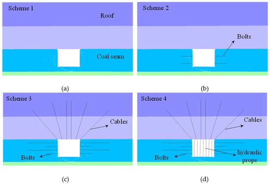
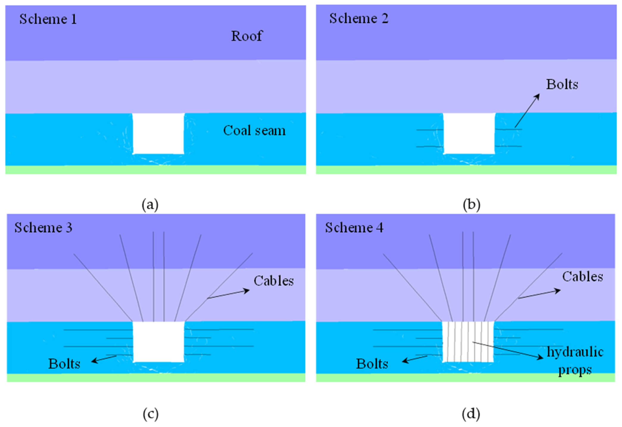
The four schemes were selected to represent typical roadway support configurations commonly adopted in Chinese coal mines and to evaluate the effects of progressively reinforced support systems, as shown in Figure 5. Scheme 1 was the unsupported reference; Scheme 2 used two 2.3 m-long rib bolts per rib; Scheme 3 added two 6.5 m-long cables per rib and six 6.5 m-long roof cables, and Scheme 4 supplemented the Scheme 3 configuration with seven hydraulic props. Bolts and cables were modeled using UDEC structural cable elements. Reinforcement steel was assigned a density of 7500 kg/m3 and Young’s modulus of 200 GPa. The tensile capacities and initial pretensions were 200 and 100 kN for the bolts, respectively, and 500 and 200 kN for the cables, respectively. Hydraulic props were represented by compressive axial support elements with a stiffness of 20 MN/m and a compressive capacity of 500 kN each. The along-roadway spacing of 0.8 m was accounted for in the equivalent two-dimensional support representation.
Figure 5.
Numerical models of the four support schemes: (a) Scheme 1, unsupported; (b) Scheme 2, bolt support; (c) Scheme 3, combined bolt–cable support; (d) Scheme 4, combined bolt–cable and hydraulic prop support.
4. Dynamic Response Under Different Support Conditions
4.1. Roadway Deformation
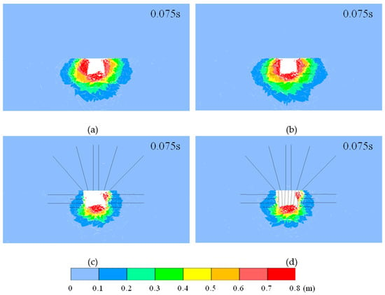
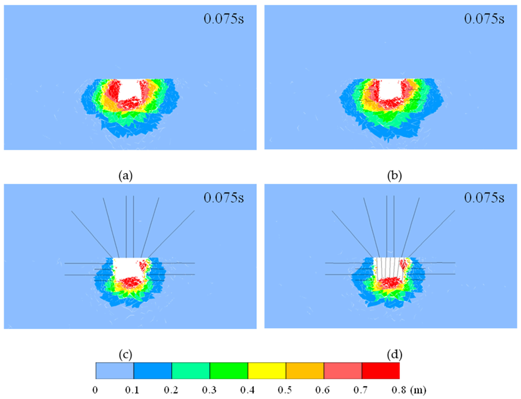
Figure 6 shows the roadway displacement distributions at 0.075 s under the four support conditions. Both the magnitude and spatial extent of deformation vary markedly among the schemes. Figure 6a shows that, under the unsupported condition, large deformation zones develop around both ribs and the bottom coal and extend into the deeper surrounding rock. Figure 6b shows that the area of large deformation decreases with bolt support, but the improvement remains limited. As shown in Figure 6c, when combined bolt and cable support is adopted, the large deformation zones in the ribs contract substantially, and their extension into the deeper coal is effectively restricted. The remaining large displacement is concentrated mainly in the shallow rib regions and bottom coal, indicating that the cables improve coordinated load transfer between the shallow fractured coal and the more stable deep coal mass. Nevertheless, bottom coal deformation remains pronounced. Figure 6d shows that, after hydraulic props are added, the displacement pattern remains broadly similar to that of Scheme 3, and the largest deformation is still concentrated beneath the roadway. Overall, the transition from bolt support to combined bolt and cable support produces the most pronounced reduction in rib deformation.
Figure 6.
Displacement distributions around the roadway under different support schemes at 0.075 s: (a) Scheme 1; (b) Scheme 2; (c) Scheme 3; (d) Scheme 4.
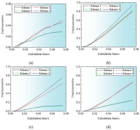
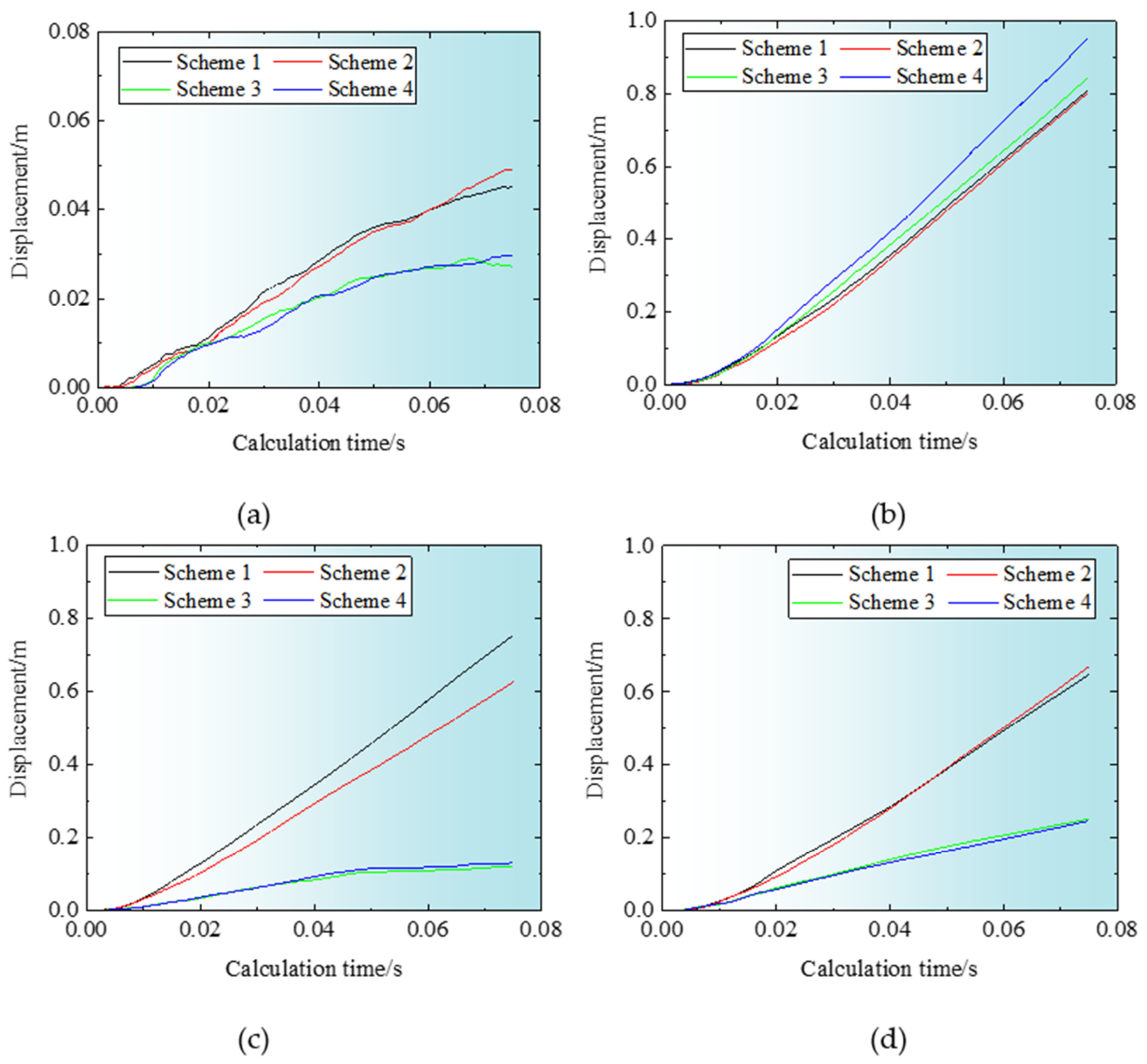
Figure 7 compares the displacement changes at different roadway locations. Roof displacement is greater in Scheme 1 and Scheme 2 than in Scheme 3 and Scheme 4, indicating that roof cables improve coordinated load transfer between the shallow and deep roof strata and thereby restrain roof deformation. The rib response is more sensitive to the support configuration. Under the unsupported condition, rib displacement increases rapidly, whereas bolt support provides only a modest reduction. The maximum left rib displacements for Scheme 1, Scheme 2, Scheme 3 and Scheme 4 are approximately 0.75, 0.62, 0.12, and 0.13 m, respectively, and the corresponding right rib maxima are 0.65, 0.67, 0.25, and 0.25 m. Thus, the addition of cables markedly suppresses rib deformation, whereas the further addition of hydraulic props provides little additional improvement. At the bottom monitoring point, displacement increases continuously, and the differences among the four schemes are comparatively small, indicating that the support systems considered here do not directly restrain deformation of the bottom coal.
Figure 7.
Displacement at different positions under the four support schemes: (a) roof; (b) bottom coal; (c) left rib; (d) right rib.
To further assess the reliability of the numerical results, the simulated roadway deformation under Scheme 2 was compared with field observations from the April 2018 coal burst. As described in Section 2.2, the estimated event-associated displacement increments of the left rib, right rib, and bottom coal were 0.70, 0.65, and 0.88 m, respectively, after subtracting the pre-event deformation from the cumulative measurements. The corresponding simulated displacements under Scheme 2 were approximately 0.62, 0.67, and 0.80 m, with relative differences of 11.43%, 3.08%, and 9.09%, respectively. The numerical results are in reasonable agreement with the field-derived deformation increments, indicating that the model can approximately reproduce the deformation characteristics of the roadway under dynamic loading.
4.2. Stress Distribution
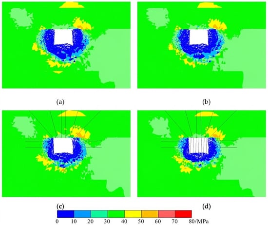
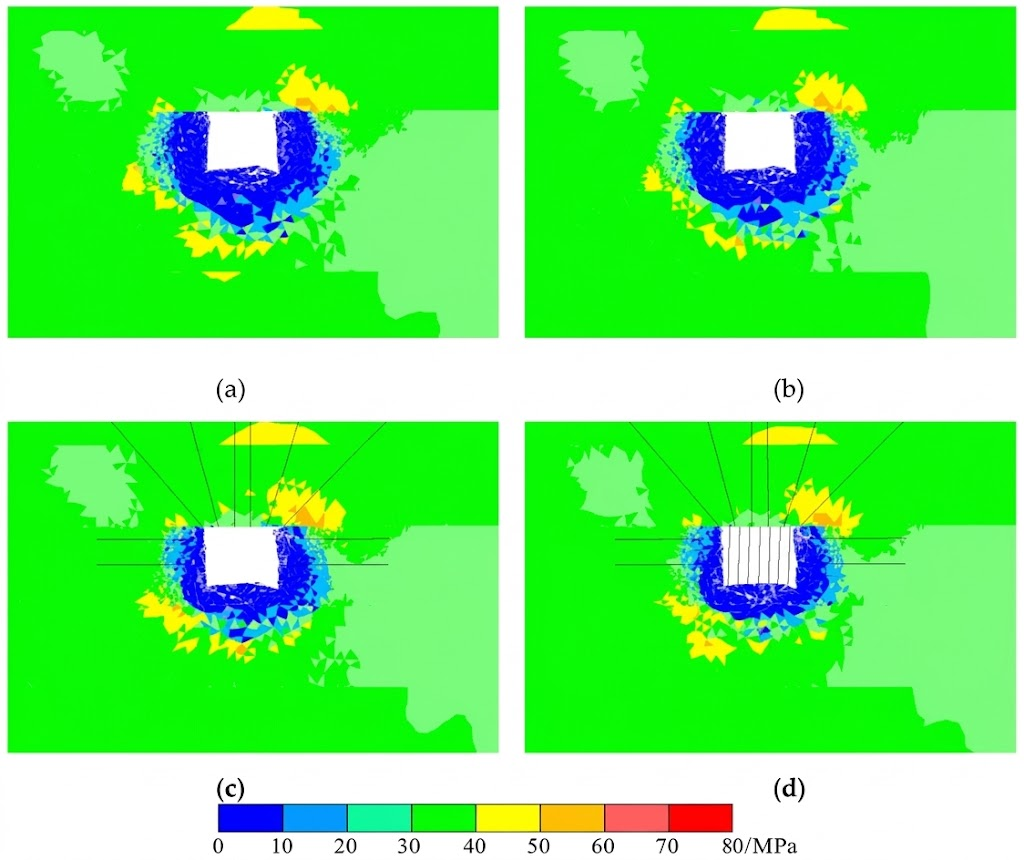
Figure 8 compares the maximum principal stress distribution around the roadway for all four support configurations. The same stress component and color scale are shown for all four schemes. Under Scheme 1, stress relief near the roadway surface is accompanied by stress concentration in the deeper surrounding rock. Bolt support modifies the local stress field but has a relatively limited effect on the overall failure response. Combined bolt–cable support changes the extent and location of the stress redistribution zone, reflecting improved load transfer between the fractured shallow rock and the relatively stable deeper rock. With hydraulic props added in Scheme 4, the maximum principal stress pattern remains broadly comparable to that of Scheme 3, indicating that the additional props do not produce a clearly distinct overall stress redistribution benefit under the prescribed dynamic loading.
Figure 8.
Maximum principal stress distributions around the roadway: (a) Scheme 1; (b) Scheme 2; (c) Scheme 3; (d) Scheme 4.
4.3. Dynamic Response
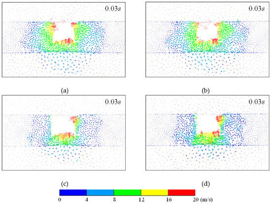
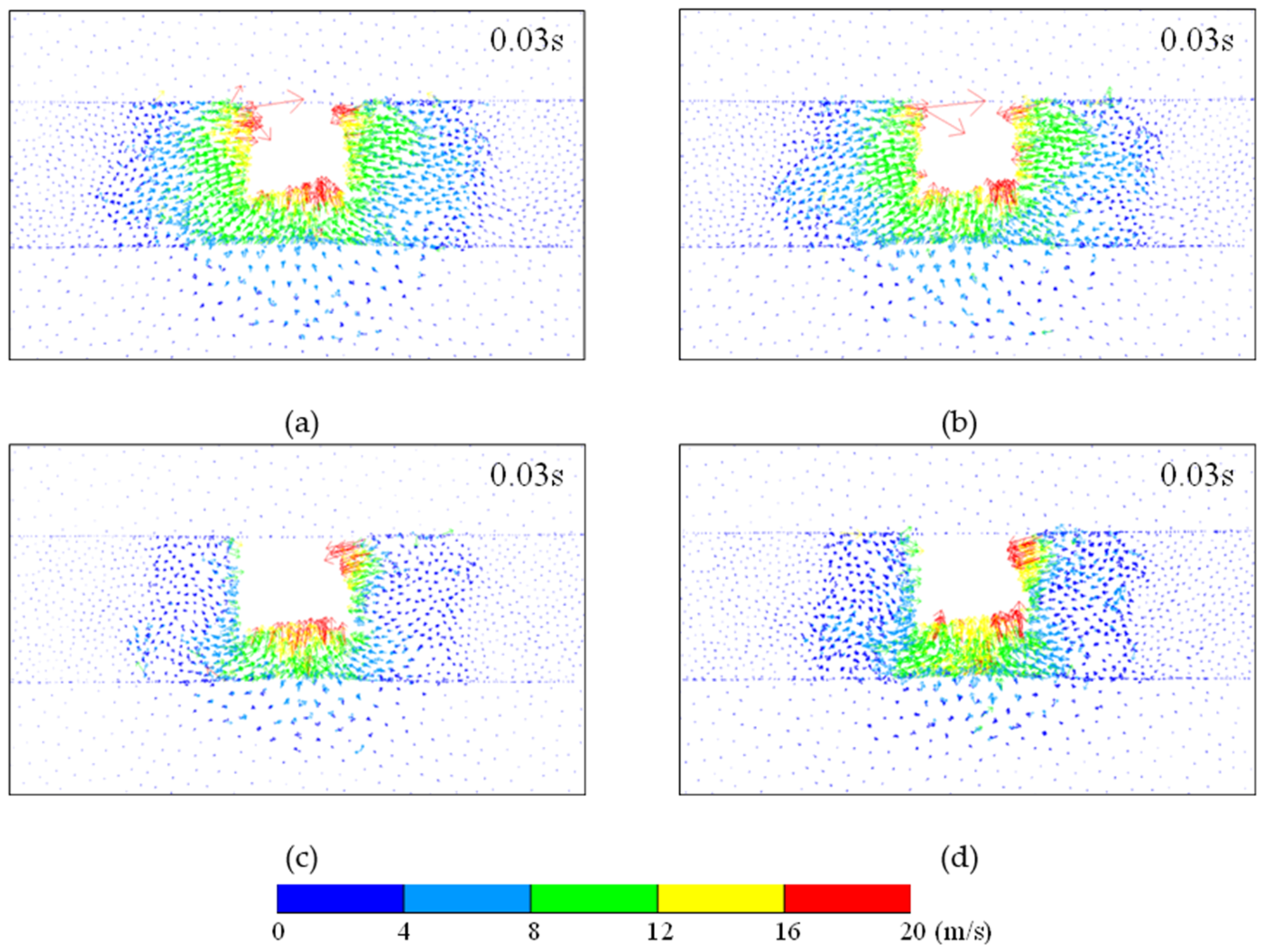
Figure 9 shows the velocity vector distributions during roadway dynamic failure. Figure 9a shows that distinct high-velocity zones develop in both ribs and the bottom coal under the unsupported condition. High-velocity vectors are concentrated near the roadway surface and gradually decay with distance into the surrounding rock, while broader zones of medium and low velocity remain outside the ribs, indicating large-scale coal and rock motion. Figure 9b shows that the high-velocity zones in the ribs decrease slightly with bolt support, but the overall velocity field pattern changes little. This suggests that bolts provide some confinement to the shallow coal but are insufficient on their own to suppress high-velocity motion caused by dynamic disturbance. As shown in Figure 9c, the velocity field changes markedly when combined bolt and cable support is adopted. The extensive high-velocity regions in the ribs are substantially reduced; high velocities become concentrated mainly in the shallow ribs and bottom coal, and the disturbed region in the deeper surrounding rock contracts. This indicates that cables couple the shallow fractured coal to the more stable deep rock mass and thereby restrain ejection toward the roadway opening. After hydraulic props are added, the velocity field in Scheme 4 remains similar to that in Scheme 3. High-velocity rib zones remain limited, whereas a pronounced high-velocity region persists in the bottom coal. Overall, the main difference among the support schemes lies in the extent of the high-velocity rib ejection zone and the deeper low-velocity disturbance zone, confirming that interaction between bolts and cables is the key factor in reducing the dynamic response of the ribs.
Figure 9.
Velocity vector distributions around the roadway under different support schemes at 0.03 s: (a) Scheme 1; (b) Scheme 2; (c) Scheme 3; (d) Scheme 4.
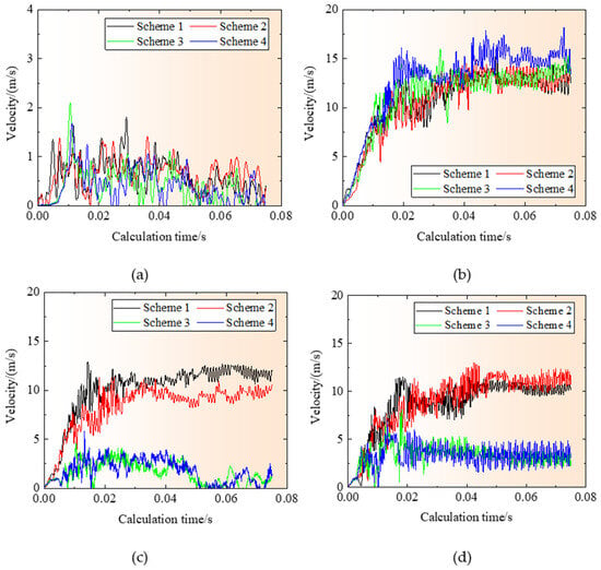
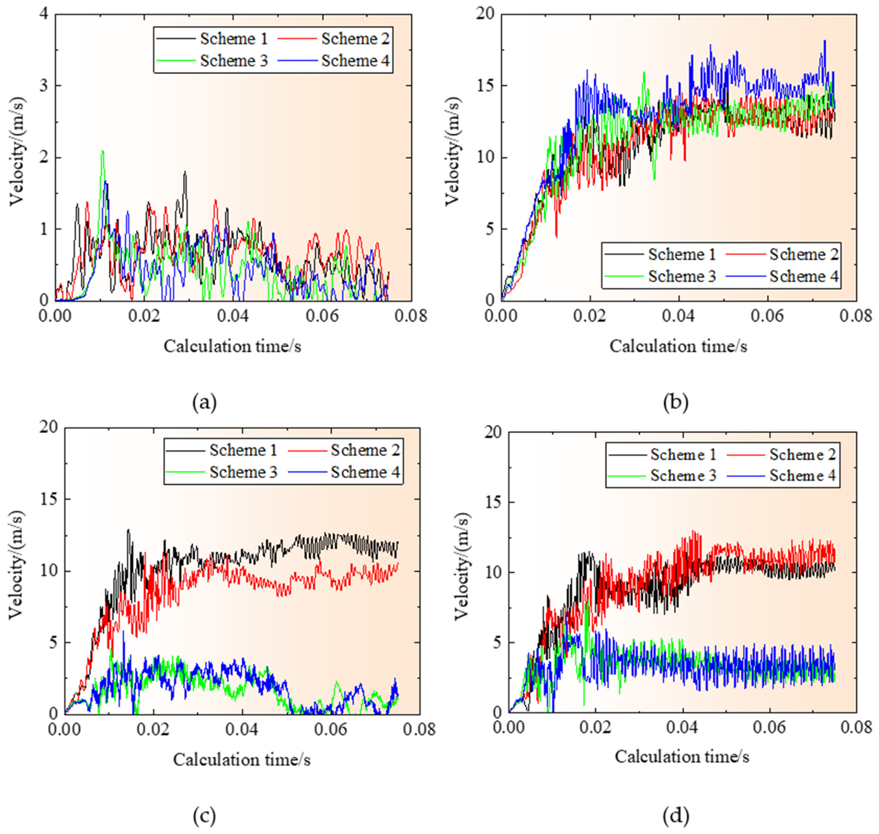
Figure 10 compares the velocity changes at the roof, bottom coal, and two ribs. The roof velocity increases rapidly after dynamic loading, fluctuates during the response, and then gradually decays. The peak roof velocities for Scheme 1, Scheme 2, Scheme 3 and Scheme 4 are 1.80, 1.39, 2.09, and 1.67 m/s, respectively. Because the roof strata do not undergo evident dynamic failure in the simulations, the support configuration has only a limited influence on the overall roof velocity response. At the bottom monitoring point, velocity increases with calculation time and remains relatively high. The four schemes show no clear separation because none of the support systems directly reinforces the bottom coal. The left rib velocities rise rapidly in Scheme 1 and Scheme 2, with peak values of 12.95 and 11.30 m/s, respectively. After cables are introduced, the corresponding peaks decrease to 4.57 and 5.69 m/s in Scheme 3 and Scheme 4. A similar trend occurs at the right rib: the peak velocities are 11.47 and 13.03 m/s in Scheme 1 and Scheme 2 and decrease to 8.02 and 6.92 m/s in Scheme 3 and Scheme 4. These results demonstrate that the bolt and cable system is particularly effective in suppressing high-velocity rib ejection. Zhang et al. [34] investigated the dynamic instability of a roadway containing a rock parting using a UDEC-Trigon model and reported a horizontal velocity of approximately 13.8 m/s at a monitoring point near the coal–rock interface. Akdag et al. [15] estimated fragment ejection velocities of 10.5–19.8 m/s based on the kinetic energy derived from polyaxial burst tests and assumed fragment masses. This result is comparable in magnitude to the velocities obtained in our numerical simulations.
Figure 10.
Velocity changes at different positions under the four support schemes: (a) roof; (b) bottom coal; (c) left rib; (d) right rib.
The roof response demonstrates that reduced displacement does not necessarily imply a lower instantaneous peak velocity: Scheme 3 produces the highest roof peak velocity (2.09 m/s) despite lower roof displacement than Scheme 1 and Scheme 2. Reinforcement modifies the timing and distribution of transient motion, while total displacement depends on the integrated velocity response.
4.4. Crack Evolution and Failure Modes
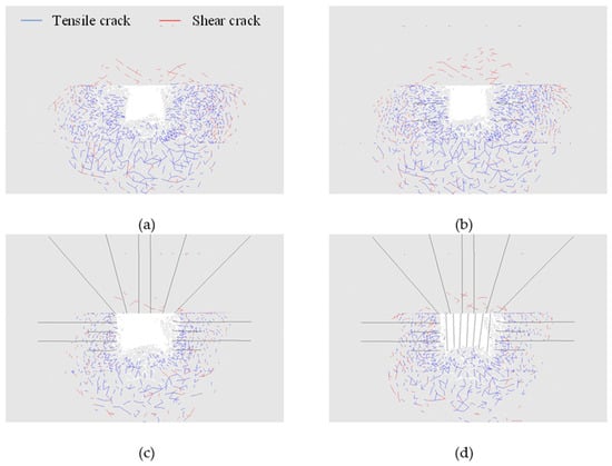
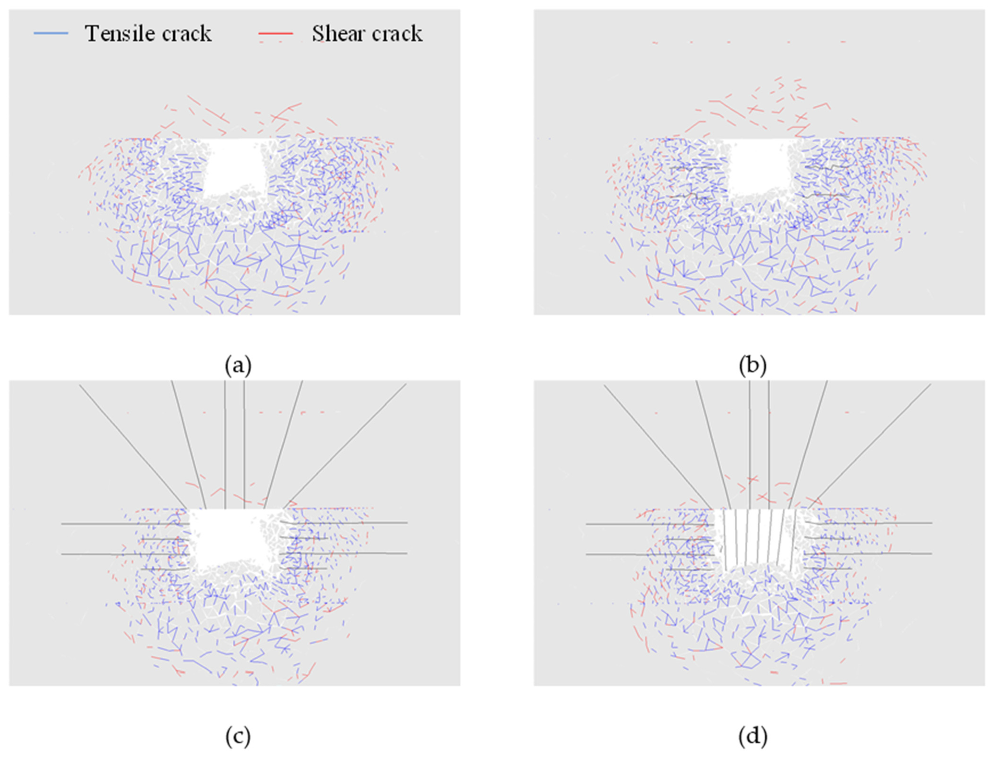
Figure 11 compares the tensile and shear crack distributions under the four support schemes. Tensile cracks occupy a wider region than shear cracks and are concentrated mainly in the shallow rock and coal around the two ribs and roadway bottom, whereas fewer shear cracks occur and are more commonly distributed in deeper regions. Figure 11a shows that, under Scheme 1, extensive tensile cracking develops in the ribs and bottom coal and extends toward the deeper surrounding rock, accompanied by a number of shear cracks in the deeper zone. Figure 11b shows that local crack propagation is slightly reduced with bolt support, but the overall failure extent changes little and dense tensile cracking remains around the ribs and bottom coal. As shown in Figure 11c, under combined bolt and cable support, the crack development zone around the ribs and roof contracts markedly, and cracks become concentrated mainly in the shallow ribs and bottom region. This indicates that the cables enhance coordinated load transfer between shallow fractured rock and deeper stable rock and thereby restrict further crack propagation. Figure 11d shows that the additional hydraulic props in Scheme 4 produce no obvious further change in crack distribution compared with Scheme 3. The largest improvement therefore occurs when the support system changes from bolt support to combined bolt and cable reinforcement.
Figure 11.
Distribution of tensile and shear cracks around the roadway under different support schemes: (a) Scheme 1; (b) Scheme 2; (c) Scheme 3; (d) Scheme 4.
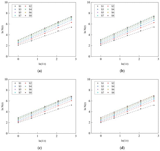
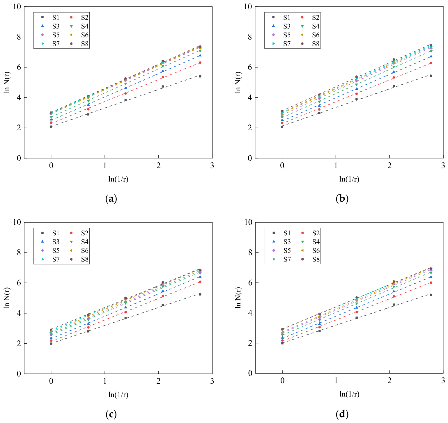
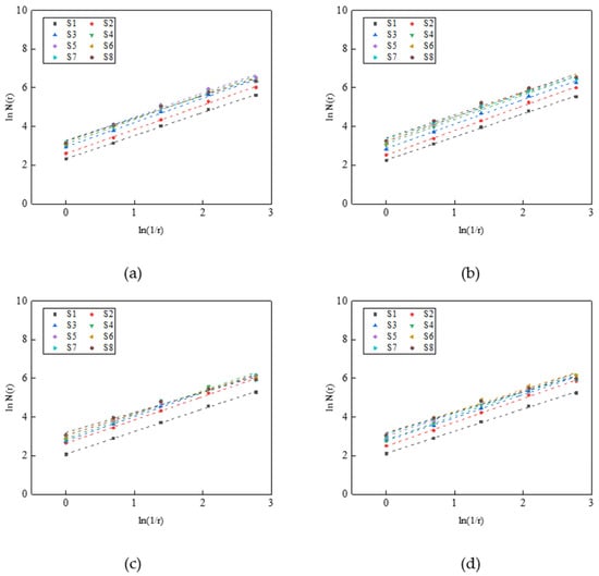
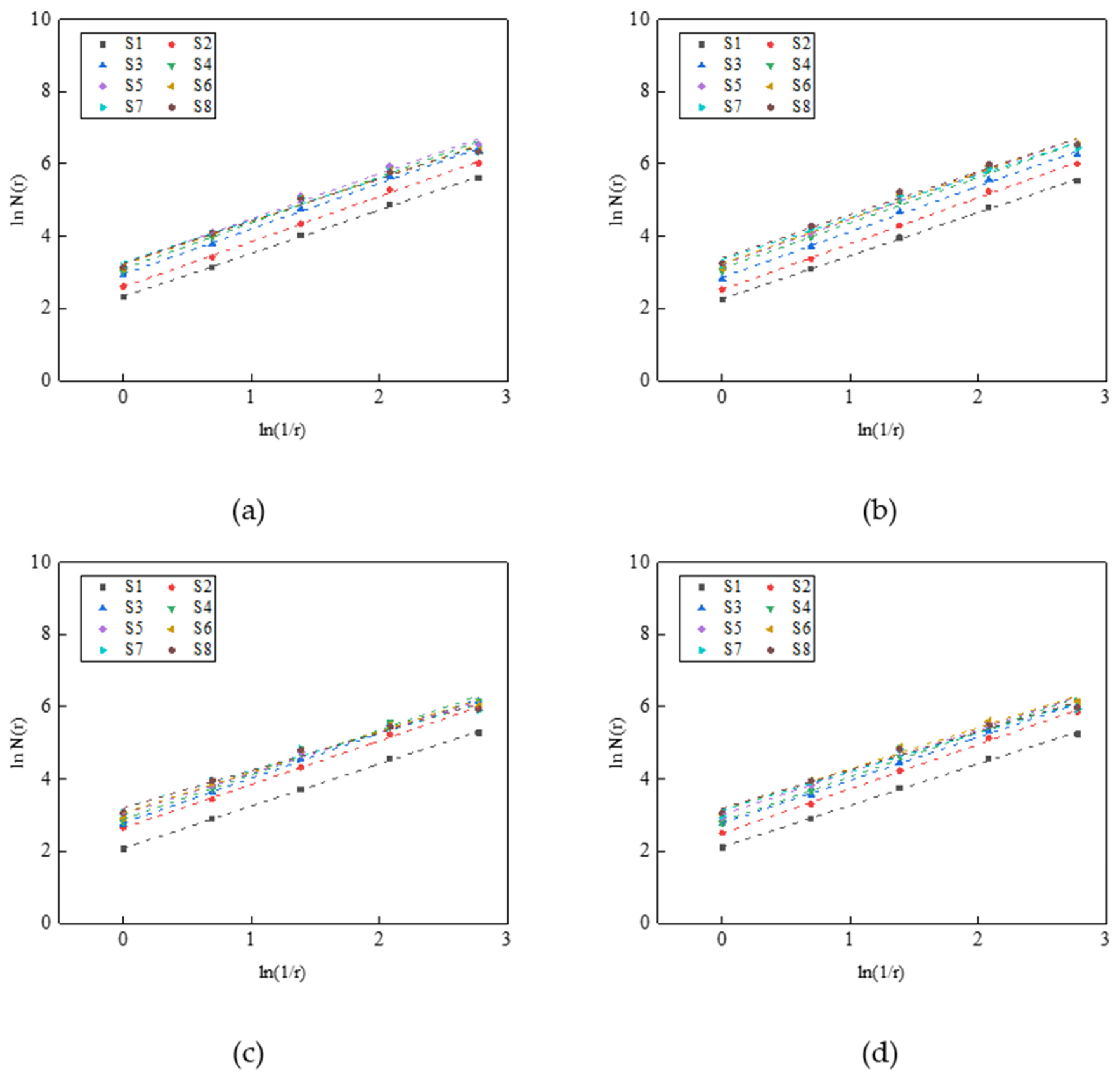
To quantitatively characterize the complexity of fracture development around the roadway, the box counting method was employed to calculate the fractal dimensions of the cracks. Based on the UDEC simulation results, tensile and shear cracks were extracted separately and converted into binary crack images for fractal analysis. A series of square grids with a side length of r were used to cover each crack image, and the number of boxes containing cracks, N(r), was counted. For a fracture pattern exhibiting fractal characteristics, N(r) follows the scaling relationship
where N(r) is the number of boxes, r is the box side length, D is the box-counting dimension of cracks, and C is a constant.
N(r) = Cr−D
Taking the natural logarithm of Equation (1) gives:
Accordingly, the fractal dimension D can be obtained from the slope of the linear regression between ln N(r) and ln(1/r). The coefficient of determination, R2, was used to evaluate the goodness of fit. In this study, Dt and Ds denote the fractal dimensions of tensile and shear cracks, respectively. A larger fractal dimension indicates a more spatially complex and extensively developed fracture network. The tensile and shear crack maps were extracted separately, converted into binary images of 1868 × 1302 pixels, and cropped to the same rectangular physical region around the roadway for all four schemes. Box-counting fits used square boxes of 16, 32, 64, 128 and 256 pixels.
Eight selected fracture-evolution stages are labeled S1–S8 in the figures and tables. The fitting results for tensile cracks are shown in Figure 12, and the corresponding fractal dimensions are listed in Table 3. The coefficients of determination range from 0.9965 to 0.9994, indicating a high goodness of fit. Under unsupported and bolt-supported conditions, the tensile crack fractal dimension increases rapidly and remains high at later stages. For Scheme 1, Dt increases from 1.2236 to 1.5919. For Scheme 2, Dt increases from 1.2259 to a peak of 1.6069 and ends at 1.5860. The results indicate that bolt support alone does not substantially reduce the spatial complexity of the tensile crack network. With combined bolt and cable support, the tensile crack fractal dimension is markedly lower. In Scheme 3, Dt increases from 1.1903 to a maximum of 1.5002 and then decreases to 1.4435. In Scheme 4, it increases from 1.1766 to 1.5264 and finally decreases to 1.4702. The mean Dt values over the full process are 1.5188, 1.5216, 1.4371, and 1.4425 for Scheme 1, Scheme 2, Scheme 3 and Scheme 4, respectively. Relative to Scheme 1, the mean values for Scheme 3 and Scheme 4 decrease by approximately 5.38% and 5.03%, and the final stage values decrease by approximately 9.32% and 7.64%, respectively. These results show that the introduction of cables effectively limits continued tensile crack propagation and fracture network complexity, whereas adding hydraulic props to the bolt and cable system provides little additional reduction.
Figure 12.
Representative box-counting fitting results for tensile cracks under the four support schemes: (a) Scheme 1; (b) Scheme 2; (c) Scheme 3; (d) Scheme 4.
Table 3.
Fractal dimensions of tensile cracks under different support schemes.
The fitting results for shear cracks are shown in Figure 13, and the corresponding fractal dimensions are listed in Table 4. The coefficients of determination range from 0.9803 to 0.9993. In contrast to the tensile cracks, Ds generally increases first and then decreases. The peak Ds values for Scheme 1 and Scheme 2 are 1.2731 and 1.2735, and the corresponding final values are 1.1677 and 1.1910, indicating similar evolution. In Scheme 3 and Scheme 4, the peak values decrease to 1.2379 and 1.2365, and the final values further decrease to 1.0400 and 1.0616, respectively. The mean Ds values over the full process are 1.2182, 1.2325, 1.1472, and 1.1568. Relative to Scheme 1, the mean values for Scheme 3 and Scheme 4 are reduced by approximately 5.83% and 5.04%, and the final stage values are reduced by approximately 10.94% and 9.09%, respectively. These results indicate that the transition from bolt support to combined bolt and cable support suppresses both tensile- and shear crack network development, whereas the additional hydraulic props produce only a minor further change in crack complexity.
Figure 13.
Representative box-counting fitting results for shear cracks under the four support schemes: (a) Scheme 1; (b) Scheme 2; (c) Scheme 3; (d) Scheme 4.
Table 4.
Fractal dimensions of shear cracks under different support schemes.
5. Field Application
5.1. Support Optimization and Roof Pre-Splitting Blasting
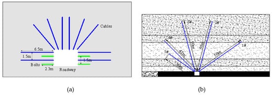
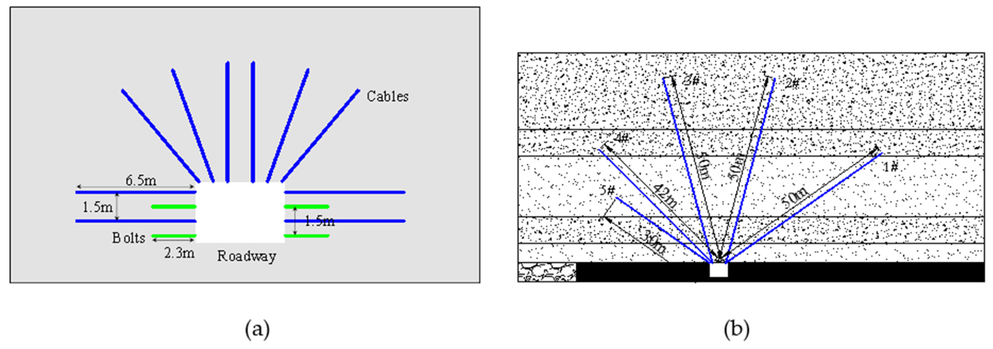
Based on the numerical results, a combined bolt–cable support system was adopted in the roadway of the 3102 working face, as shown in Figure 14a. During the period of high dynamic failure risk, the support spacing along the roadway axis was set to 0.8 m, while the vertical spacing was 1.5 m. As mining progressed and the dynamic failure risk decreased, these spacings were adjusted to 1.0 m and 1.6 m, respectively. The support system consisted of 2.3 m long rib bolts, 6.5 m long rib cables, and six roof cables, providing coordinated reinforcement of the roadway roof and ribs.
Figure 14.
Field control measures: (a) bolt–cable support; (b) layout of roof pre-splitting blasting boreholes.
As shown in Figure 14b, roof pre-splitting blasting was implemented in combination with the reinforced support system. Five boreholes with a diameter of 75 mm were arranged in a fan-shaped pattern. The inclination angles of boreholes 1#–5# were 35°, 75°, 75°, 45°, and 35°, respectively, with corresponding borehole lengths of 50, 50, 50, 42, and 30 m. Emulsion explosives were used, with charge lengths of 27, 32, 32, 24, and 12 m and charge masses of 40.5, 48.0, 48.0, 36.0, and 18.0 kg, respectively. Cement was used as the stemming material, with a stemming length of 23 m for borehole 1# and 18 m for boreholes 2#–5#. The five boreholes in each fan were detonated in a single blasting round. Adjacent borehole fans were spaced 20 m apart along the roadway, and blasting was conducted more than 200 m ahead of the advancing working face. The pre-splitting boreholes mainly targeted the roof strata within approximately 48 m above the coal seam, promoting controlled fracturing of the lower roof and facilitating the subsequent breaking of the overlying hard roof strata.
Following the implementation of combined bolt–cable reinforcement and roof pre-splitting blasting, roadway deformation was significantly reduced. Field deformation was monitored using fixed monitoring stations arranged at 20 m intervals along the roadway, where roadway width and height were measured daily. As shown in Table 5, before optimization, a coal burst occurred in April 2018, associated with a mining-induced seismic event of 3.30 × 10⁷ J located approximately 65 m above the coal seam. After the implementation of the combined control measures, another seismic event with an energy of 2.80 × 10⁷ J was recorded in February 2019, approximately 70 m above the coal seam. The maximum roof, rib, and bottom-coal deformations decreased from 0.05, 1.0, and 0.9 m to 0.03, 0.4, and 0.4 m, respectively, corresponding to reductions of 40.0%, 60.0%, and 55.6%. Although the two seismic events differed in their loading characteristics, the field observations indicate improved roadway deformation control following the implementation of the integrated measures. As bolt–cable reinforcement and roof pre-splitting blasting were implemented simultaneously, the observed improvements reflect their combined effects.
Table 5.
Reported mining-induced seismic events and maximum roadway deformation before and after the integrated measures.
5.2. Research Limitations
The present study has several limitations. First, the bottom-coal displacement and velocity continued to increase toward the end of the observation period. This behavior may be influenced by the damping formulation and associated parameters, which require further investigation. Second, the effects of bolt and cable length, spacing, and pretension on roadway stability were not systematically investigated. Third, although the elevated static stress induced by the adjacent gob was considered through equivalent initial stresses, the two-dimensional numerical model did not explicitly reproduce the local stress redistribution associated with the gob and coal pillar. In addition, the mining-induced seismic disturbance was represented by an idealized triangular velocity pulse, and systematic sensitivity analyses of triangular block size and fractal analysis parameters were not conducted. Furthermore, the effects of roof pre-splitting blasting were not included in the numerical simulations. Future research will focus on the influence of damping models and parameters, optimization of support configurations, three-dimensional numerical modeling, and more comprehensive field monitoring.
6. Conclusions
Taking the M Coal Mine as an engineering background, this study established a UDEC-Trigon numerical model to investigate the dynamic response and failure of the roadway under mining-induced seismic loading. Four support schemes, including unsupported (Scheme 1), bolt support (Scheme 2), combined bolt and cable support (Scheme 3), and combined support with bolts, cables, and hydraulic props (Scheme 4), were compared in terms of roadway deformation, stress redistribution, velocity response, crack development, and crack fractal characteristics. The following conclusions are drawn.
- (1)
- The support configuration significantly influences roadway deformation, particularly at the ribs and roof. Compared with Scheme 1 and Scheme 2, combined bolt–cable support reduces the left-rib displacement from 0.75 and 0.62 m to 0.12 m, respectively, while the right-rib displacement decreases to approximately 0.25 m. The addition of hydraulic props provides limited further improvement and has little effect on bottom-coal deformation. Bottom-coal deformation remains significant under all four support schemes. Although combined bolt–cable support effectively controls deformation of the roadway ribs and roof, its restraining effect on the bottom coal is limited.
- (2)
- Combined bolt–cable support effectively reduces the dynamic velocity response of the roadway ribs. The peak left-rib velocities under Scheme 1, Scheme 2, Scheme 3 and Scheme 4 are 12.95, 11.30, 4.57, and 5.69 m/s, respectively, while the corresponding right-rib velocities are 11.47, 13.03, 8.02, and 6.92 m/s. Compared with bolt-only support, cable reinforcement substantially suppresses the peak rib velocities, demonstrating its effectiveness in controlling the dynamic response of the surrounding rock.
- (3)
- Tensile cracking is the dominant failure mode in the shallow surrounding rock, whereas shear cracking is more pronounced in deeper regions. Combined bolt–cable support effectively restricts crack propagation and reduces fracture network complexity. Compared with Scheme 1, the mean fractal dimensions of tensile cracks decrease by 5.38% and 5.03% under Scheme 3 and Scheme 4, respectively, while those of shear cracks decrease by 5.83% and 5.04%. The relatively small differences between Scheme 3 and Scheme 4 indicate that hydraulic props provide limited additional control over crack development.
Author Contributions
Conceptualization, J.C.; methodology, J.C.; investigation, L.Z.; software, L.D.; validation, C.L.; formal analysis, J.H.; data curation, H.L.; visualization, J.C. and L.Z.; supervision, J.H.; project administration, J.H.; funding acquisition, J.C. and L.D.; writing—original draft preparation, J.C.; writing—review and editing, J.C., L.Z., L.D., J.H., C.L. and H.L. All authors have read and agreed to the published version of the manuscript.
Funding
This research was funded by the National Natural Science Foundation of China, grant numbers 52604224 and 52227901; the Postdoctoral Fellowship Program (Grade C) of the China Postdoctoral Science Foundation, grant number GZC20241923; and the Jiangsu Funding Program for Excellent Postdoctoral Talent, grant number 2024ZB733.
Institutional Review Board Statement
Not applicable.
Informed Consent Statement
Not applicable.
Data Availability Statement
The data supporting the findings of this study are available from the corresponding author upon reasonable request.
Acknowledgments
The authors gratefully thank the anonymous reviewers for their constructive comments for improving the presentation. All authors have agreed to the listing of authors.
Conflicts of Interest
Author L.Z. was employed by Yaojie Coal and Electricity Group Corporation. The authors declare no conflicts of interest.
References
- Pan, Y.; Song, Y.; Luo, H.; Xiao, Y. Coalbursts in China: Theory, practice and management. J. Rock Mech. Geotech. Eng. 2024, 16, 1–25. [Google Scholar] [CrossRef] [Scilit]
- Li, Y. Spatial distribution of strain energy changes due to mining-induced fault coseismic slip: Insights from a rockburst at the Yuejin Coal Mine, China. Rock Mech. Rock Eng. 2025, 58, 1693–1706. [Google Scholar] [CrossRef] [Scilit]
- Cao, J.; He, J.; Dou, L.; Li, X.; Gong, S.; Kan, Z.; Ma, X.; Lu, F. Failure mechanism and mitigation of mining-induced seismicity triggered by hard and extremely thick rock strata: A numerical investigation. Comput. Part. Mech. 2026, 15, 57–74. [Google Scholar] [CrossRef] [Scilit]
- Dai, L.; Zhao, X.; Pan, Y.; Luo, H.; Gao, Y.; Wang, A.; Ding, L.; Li, P. Microseismic criterion for dynamic risk assessment and warning of roadway rockburst induced by coal mine seismicity. Eng. Geol. 2025, 357, 108324. [Google Scholar] [CrossRef] [Scilit]
- Nierobisz, A. Investigation of mine roadway support load during seismic events. J. Min. Sci. 2012, 48, 298–307. [Google Scholar] [CrossRef] [Scilit]
- Frith, R.; Reed, G.; Jones, A. A causation mechanism for coal bursts during roadway development based on the major horizontal stress in coal: Very specific structural geology causing a localised loss of effective coal confinement and Newton’s second law. Int. J. Min. Sci. Technol. 2020, 30, 39–47. [Google Scholar] [CrossRef] [Scilit]
- Ren, H.; Pan, Y.; Song, Y.; Luo, H. Critical conditions of coalburst in a rectangular roadway based on the energy extreme point method. Rock Mech. Rock Eng. 2024, 57, 10731–10745. [Google Scholar] [CrossRef] [Scilit]
- Ju, M.; Yu, L.; Zou, Y.; Hu, L.; Dou, L.; Dai, L.; Ding, M.; Yao, B. Role of coal properties and surrounding rock stiffness in coal burst triggering under superimposed dynamic loads during deep mining. Rock Mech. Rock Eng. 2026. [Google Scholar] [CrossRef] [Scilit]
- Tan, Y.; Yang, S.; Liu, X.; Naser, G.; Vahab, S.; Song, S. Mechanical mechanism of surrounding rock’s energy accumulation-release adjustment in the deep roadway. Geomech. Geophys. Geo-Energy Geo-Resour. 2026, 12, 100. [Google Scholar] [CrossRef] [Scilit]
- Zhou, C.; Song, D.; Lu, A.; Li, Z.; Jin, A.; Yin, S.; He, X.; Zhu, S.; Wei, M.; Zhong, T.; et al. Stress disturbance coefficient method for rock burst hazard identification in gully regions: A case study. Appl. Sci. 2026, 16, 8245. [Google Scholar] [CrossRef] [Scilit]
- Dai, L.; Zhao, X.; Ju, M.; Pan, Y.; Wang, A.; Xu, L.; Tian, Z. Determination of critical stress for rockburst warning: A model incorporating borehole-sensor interaction and its validation. Int. J. Rock Mech. Min. Sci. 2026, 201, 106464. [Google Scholar] [CrossRef] [Scilit]
- Liu, F.; Dai, L.; Tian, Z.; Gao, Y.; Wang, A.; Pan, Y. Visualization of bursting and collapse disaster around top coal roadways under dynamic dis-turbance: Physical and numerical modeling. Eng. Fail. Anal. 2026, 196, 111078. [Google Scholar] [CrossRef] [Scilit]
- Zuo, Y.; Li, X.; Zhou, Z. Determination of ejection velocity of rock fragments during rock burst in consideration of damage. J. Cent. South Univ. Technol. 2005, 12, 618–622. [Google Scholar] [CrossRef] [Scilit]
- Li, H.; He, M.; Xiao, Y.; Liu, D.; Hu, J.; Cheng, T. Granite strainbursts induced by true triaxial transient unloading at different stress levels: Insights from excess energy ΔE. J. Rock Mech. Geotech. Eng. 2025, 17, 7078–7092. [Google Scholar] [CrossRef] [Scilit]
- Akdag, S.; Karakus, M.; Nguyen, G.D. Experimental investigation of burst failure mechanism under polyaxial loading conditions. Rock Mech. Rock Eng. 2025, 58, 4247–4262. [Google Scholar] [CrossRef] [Scilit]
- Zhang, N.; Zhang, Z.-X.; Ouyang, Z.; Liu, Y.; Li, Y.; Xu, Q.; Liu, J.; Shi, Q. Mechanism of coalburst triggered by thrust fault slipping based on field monitoring, indoor experiments and numerical simulation. Bull. Eng. Geol. Environ. 2026, 85, 638. [Google Scholar] [CrossRef] [Scilit]
- Wu, Y.; Gao, F.; Chen, J.; He, J. Experimental study on the performance of rock bolts in coal burst-prone mines. Rock Mech. Rock Eng. 2019, 52, 3959–3970. [Google Scholar] [CrossRef] [Scilit]
- Kang, H.; Yuan, G.; Si, L.; Gao, F.; Lou, J.; Yang, J.; Dong, S. Mechanical behavior and failure mechanisms of rock bolts subjected to static-dynamic loads. Int. J. Min. Sci. Technol. 2024, 34, 281–288. [Google Scholar] [CrossRef] [Scilit]
- Wang, Q.; Wang, M.; Xu, S.; Jiang, B.; Duan, R. Dynamic characteristics and energy absorption mechanism of prestressed an-chorage support. Tunn. Undergr. Space Technol. 2025, 163, 106759. [Google Scholar] [CrossRef] [Scilit]
- Wu, Y.; He, S.; Fu, Y.; Li, J.; Zhou, P.; Sun, Z. Experimental study on the failure evolution of surrounding rock and the response of bolt support under multiple impact loads in mine roadways. Rock Mech. Rock Eng. 2025, 58, 3779–3797. [Google Scholar] [CrossRef] [Scilit]
- Batan, C.K.; Akdag, S.; Zhang, C.; Oh, J.; Holden, M.; Craig, P.; Mikula, P.; Canbulat, I.; Saydam, S. Assessment of the performance of ground support system in burst-prone areas. Rock Mech. Rock Eng. 2025, 58, 4281–4302. [Google Scholar] [CrossRef] [Scilit]
- Pytel, W.; Pałac-Walko, B.; Butra, J.; Mertuszka, P. Friction stabilizers for rock bursts hazard mitigation in deep mines’ environments. Tunn. Undergr. Space Technol. 2026, 168, 107096. [Google Scholar] [CrossRef] [Scilit]
- Zhu, C.; Huang, M.; He, M.; Jiang, Y.; Zheng, H.; Jiang, Y.; Wu, Z. Shear-induced deformation and energy evolution of NPR rock bolts under varying constant normal stiffness. Rock Mech. Rock Eng. 2026, 59, 6445–6458. [Google Scholar] [CrossRef] [Scilit]
- Xu, Z.; Xiao, X.; Qi, J.; Fan, Y.; Zhang, W.; Li, Z. Parametric optimization of sinusoidal curve negative Poisson’s ratio energy absorbing structures. Tunn. Undergr. Space Technol. 2026, 172, 107509. [Google Scholar] [CrossRef] [Scilit]
- Zhang, J.; Zhang, Y.; Han, Y.; Fan, W.; Song, Z.; Yu, H.; Zhang, J.; Zhang, H.; Liu, J. Study on stress distribution law of surrounding rock of roadway under the goaf and mechanism of pressure relief and impact reduction. Eng. Fail. Anal. 2024, 160, 108210. [Google Scholar] [CrossRef] [Scilit]
- Zhang, Y.; Cui, B.; Feng, G.; Zhang, C.; Guo, Y.; Zhang, S.; Zhang, Z. Shear mechanical properties of loaded rock under drilling and dynamic load and its influence on the plastic zone of roadway. Int. J. Min. Sci. Technol. 2025, 35, 1073–1091. [Google Scholar] [CrossRef] [Scilit]
- Yu, S.; Suo, Y.; Cai, C.; Feng, J.; Huo, X.; Hu, J.; Ren, J. Failure mechanism of surrounding rock and synergistic control of strong support-strong pressure relief for lower seam roadways in close-distance coal seam groups. Sci. Rep. 2026, 16, 15843. [Google Scholar] [CrossRef] [Scilit] [PubMed]
- Liu, W.; Yang, K.; Hua, X.; Ma, Y.; Deangeli, C.; Zhang, Y. Rockburst mechanism in gob-side roadways induced by zonal energy release from thick-hard roof failure. Lithosphere 2026, 2026, lithoshere_2026_110. [Google Scholar] [CrossRef] [Scilit]
- Chen, G.; Shen, Y.; Li, T.; Zhang, J.; Wang, E.; Wang, C.; Liu, Y.; Zhang, G. Discrete-element analysis and constitutive model for coal with predefined voids. Comput. Part. Mech. 2026, 13, 41–64. [Google Scholar] [CrossRef] [Scilit]
- Zhang, S.; Jiang, Q.; Qiu, S.; Li, S.; Kou, Y.; Xu, D. Assessment of strain bursting using a Voronoi-based breakable block model: A case study of 2400-m-deep tunnels. Eng. Fract. Mech. 2025, 318, 110930. [Google Scholar] [CrossRef] [Scilit]
- Qiu, S.; Zhang, S.; Jiang, Q.; Fang, Y.; Li, P.; Li, S.; Xiao, Y.; Xu, D. Excavation-induced fracturing mechanisms in deep hard rock: A hierarchical block model. Undergr. Space 2026, 26, 1–21. [Google Scholar] [CrossRef] [Scilit]
- Gao, F.; Stead, D.; Kang, H. Numerical simulation of squeezing failure in a coal mine roadway due to mining-induced stresses. Rock Mech. Rock Eng. 2015, 48, 1635–1645. [Google Scholar] [CrossRef] [Scilit]
- Cao, J.; Dou, L.; Konietzky, H.; Zhou, K.; Zhang, M. Failure mechanism and control of the coal bursts triggered by mining-induced seismicity: A case study. Environ. Earth Sci. 2023, 82, 168. [Google Scholar] [CrossRef] [Scilit]
- Zhang, H.; Zhang, Y.-G.; Liu, G.-J.; Zhu, Y.-W.; Ji, X.-J.; Cao, W.-H. Numerical study on the characteristics of roadway failure and instability in coal seam with rock parting. Sci. Rep. 2024, 14, 1587. [Google Scholar] [CrossRef] [Scilit] [PubMed]

Disclaimer/Publisher’s Note: The statements, opinions and data contained in all publications are solely those of the individual author(s) and contributor(s) and not of MDPI and/or the editor(s). MDPI and/or the editor(s) disclaim responsibility for any injury to people or property resulting from any ideas, methods, instructions or products referred to in the content. |
© 2026 by the authors. Licensee MDPI, Basel, Switzerland. This article is an open access article distributed under the terms and conditions of the Creative Commons Attribution (CC BY) license.